Embed Size (px)
Citation preview
Instruction Manual for
Monroe Electronics, Inc.
Multi-Point Fieldmeter and Alarm System
Model 177A
Specifications subject to change without notice. P/N 0340184
013118 Firmware v 1.12 Software v1.05
100 Housel Ave PO Box 535 Lyndonville NY 14098 585-765-2254 fax: 585-765-9330 monroe-electronics.com
TABLE OF CONTENTS
WARRANTY ..................................................................................................... Page 2 RETURN POLICIES AND PROCEDURES ..................................................... Page 2 Section 1 GENERAL ........................................................................................................ Page 3
Section 2 SPECIFICATIONS ........................................................................................... Page 4
Section 3 ELECTRONIC FIELDS AND FIELDMETERS ................................................. Page 5
Section 4 INSTALLATION ................................................................................................ Page 8
Section 5 PRINCIPLE OF OPERATION ........................................................................ Page 10
Section 6 USING 1036E AND 1036F SENSORS .......................................................... Page 11
Section 7 TYPICAL SETUP ........................................................................................... Page 17
Section 8 OPERATION .................................................................................................. Page 18
Section 9 177A SOFTWARE.......................................................................................... Page 22
Section 10 PROGRAMMING VIA THE FRONT PANEL .................................................. Page 28
Section 11 OPTIONAL 4 – 20 mA MODULE ................................................................... Page 29
Section 12 UPGRADING THE FIRMWARE ..................................................................... Page 32
APPENDIX I PROBE CONNECTION OPTIONS
APPENDIX II INTRINSIC SAFETY BARRIERS
APPENDIX III RS-485 CONNECTION DATA
APPENDIX IV MODBUS PROTOCOL
APPLICATION NOTE APNE-0003 - Fieldmeter Measurement Techniques Using Model 1036 Probes
APPLICATION NOTE APNE-0014 - Electrostatic Charging In Web Converting APPLICATION NOTE APNE-0015 - Electric Fields and Fieldmeters in Web Converting APPLICATION NOTE APNE-0016 - Static Control in Web Converting
Accessories Included: Manual 110V Line Cord 220V Line Cord
DB9 M/F Straight-Thru Cable USB A-Male/B-Male Cable Mounting Hardware 2 – 2 Position terminal block plugs 4 – 6 Position terminal plugs

2
WARRANTY
Monroe Electronics, Inc., warrants to the Owners, this instrument to be free from defects in material and workmanship for a period of two years after shipment from the factory. This warranty is applicable to the original purchaser only. Liability under this warranty is limited to service, adjustment or replacement of defective parts (other than tubes, fuses or batteries) on any instrument or sub-assembly returned to the factory for this purpose, transportation prepaid. This warranty does not apply to instruments or sub-assemblies subjected to abuse, abnormal operating conditions, or unauthorized repair or modification. Since Monroe Electronics, Inc. has no control over conditions of use, no warranty is made or implied as to the suitability of our product for the customer’s intended use. THIS WARRANTY SET FORTH IN THIS ARTICLE IS EXCLUSIVE AND IN LIEU OF ALL OTHER WARRANTIES AND REPRESENTATIONS, EXPRESS, IMPLIED OR STATUTORY INCLUDING BUT NOT LIMITED TO THE IMPLIED WARRANTIES OF MERCHANTABILITY AND FITNESS. Except for obligations expressly undertaken by Monroe Electronics, in this Warranty, Owner hereby waives and releases all rights, claims and remedies with respect to any and all guarantees, express, implied, or statutory (including without limitation, the implied warranties of merchantability and fitness), and including but without being limited to any obligation of Monroe Electronics with respect to incidental or consequential damages, or damages for loss of use. No agreement or understanding varying or extending the warranty will be binding upon Monroe Electronics unless in writing signed by a duly authorized representative of Monroe Electronics. In the event of a breach of the foregoing warranty, the liability of Monroe Electronics shall be limited to repairing or replacing the non-conforming goods and/or defective work, and in accordance with the foregoing, Monroe Electronics shall not be liable for any other damages, either direct or consequential.
RETURN POLICIES AND PROCEDURES FACTORY REPAIR Return authorization is required for factory repair work. Material being returned to the factory for repair must have a Return Material Authorization number. To obtain an RMA number, call 585-765-2254 and ask for Customer Service. Material returned to the factory for warranty repair must be accompanied by a copy of a dated invoice or bill of sale, which serves as a proof of purchase for the material. Repairs will be returned promptly. Repairs are normally returned to the customer by UPS within ten working days after receipt by Monroe Electronics, Inc. Return (to the customer) UPS charges will be paid by Monroe Electronics on warranty work. Return (to the customer) UPS charges will be prepaid and added to invoice for out-of-warranty repair work. EXPEDITED FACTORY REPAIR: All material returned to the factory by air or by an overnight service will be expedited. Expedited factory repairs will be returned to the customer by the same mode of transportation by which the material was returned to the factory for repair (i.e., material returned to the factory by an overnight service will be returned to the customer by an overnight service). NOTE: Return (to the customer) transportation expenses for expedited factory repairs will always be at the expense of the customer despite the warranty status of the equipment. FACTORY REPAIRS TO MODIFIED EQUIPMENT: Material returned to the factory for repair that has been modified will not be tested unless the nature and purpose of the modification is understood by us and does not render the equipment untestable at our repair facility. We will reserve the right to deny service to any modified equipment returned to the factory for repair regardless of the warranty status of the equipment.

3
Section 1
GENERAL Monroe Electronics’ Multi-Point Fieldmeter and Alarm System, Model 177A measures electrostatic fields (potential gradient) in terms of voltage per unit distance. Using probe-to-surface separation as a calibration factor enables use of this instrument for measurement of surface voltage as well. As with other models of Monroe Electronics’ electrostatic fieldmeters, the Model 177A’s primary application is measurement and monitoring of electrostatic charge accumulation. As a charge increases on the surface of a material, the electrostatic field in the vicinity increases proportionately. The Model 177A Multi-Point Fieldmeter and Alarm System produces a reliable output signal directly proportional to the surface charge accumulation while making NO PHYSICAL CONTACT with the material being monitored. The Monroe Electronics Model 177A is an intrinsically safe system, using FM-listed Monroe Electronics Model 1036 sensors, which continuously monitor the critical points in your facility to detect and warn of electrostatic charge buildup before it becomes a problem. In a typical alarm-activated or PLC-connected setup, as static levels in your application surpass a preset value, beyond which there may be a danger to personnel or possible disruption or destruction to the process or product, an initial warning is triggered and the process is allowed to continue. If the problem is rectified, the “warning” returns to a “normal” state. If the condition persists and the static level exceeds a second, more crucial value, an alarm is activated. This second-level alarm can be used to shut down the process until it is brought under control, or to further warn the operator of the more serious condition. Each Model 177A will monitor up to four locations using Monroe Model 1036 sensors placed at distances up to 1000 feet from the instrument. Processes can be continuously monitored and recorder outputs may be utilized for long term, drift free data acquisition. Cascading of up to 32 units via RS485 permits monitoring of up to 128 sensor locations using a PC and the supplied software. Factory Mutual Research Corp. approves the Model 1036 probes for use in Class I, Division 1, Groups C and D hazardous locations. To comply, approved intrinsic safety (IS) barriers must be used with the Model 1036. Reference FM Standard Class Number 3610:January 2000
This document provides the user, for hazardous and non-hazardous areas, with operational instructions for Monroe Model 1036 sensors and the corresponding Model 177A Fieldmeter/Alarm System.
4
Section 2
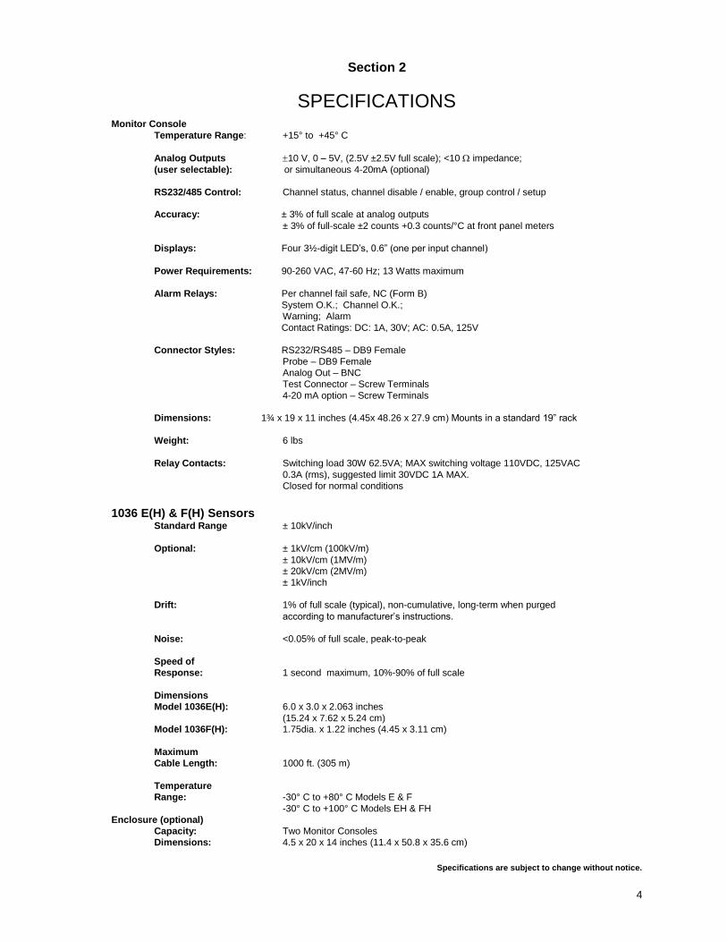
SPECIFICATIONS
Monitor Console
Temperature Range: +15° to +45° C
Analog Outputs 10 V, 0 – 5V, (2.5V ±2.5V full scale); <10 impedance;
(user selectable): or simultaneous 4-20mA (optional)
RS232/485 Control: Channel status, channel disable / enable, group control / setup
Accuracy: ± 3% of full scale at analog outputs
± 3% of full-scale ±2 counts +0.3 counts/°C at front panel meters
Displays: Four 3½-digit LED’s, 0.6” (one per input channel)
Power Requirements: 90-260 VAC, 47-60 Hz; 13 Watts maximum
Alarm Relays: Per channel fail safe, NC (Form B)
System O.K.; Channel O.K.;
Warning; Alarm
Contact Ratings: DC: 1A, 30V; AC: 0.5A, 125V
Connector Styles: RS232/RS485 – DB9 Female
Probe – DB9 Female
Analog Out – BNC
Test Connector – Screw Terminals
4-20 mA option – Screw Terminals
Dimensions: 1¾ x 19 x 11 inches (4.45x 48.26 x 27.9 cm) Mounts in a standard 19” rack
Weight: 6 lbs
Relay Contacts: Switching load 30W 62.5VA; MAX switching voltage 110VDC, 125VAC
0.3A (rms), suggested limit 30VDC 1A MAX.
Closed for normal conditions
1036 E(H) & F(H) Sensors Standard Range ± 10kV/inch
Optional: ± 1kV/cm (100kV/m)
± 10kV/cm (1MV/m)
± 20kV/cm (2MV/m)
± 1kV/inch
Drift: 1% of full scale (typical), non-cumulative, long-term when purged
according to manufacturer’s instructions.
Noise: <0.05% of full scale, peak-to-peak
Speed of
Response: 1 second maximum, 10%-90% of full scale
Dimensions
Model 1036E(H): 6.0 x 3.0 x 2.063 inches
(15.24 x 7.62 x 5.24 cm) Model 1036F(H): 1.75dia. x 1.22 inches (4.45 x 3.11 cm)
Maximum
Cable Length: 1000 ft. (305 m)
Temperature
Range: -30° C to +80° C Models E & F
-30° C to +100° C Models EH & FH
Enclosure (optional)
Capacity: Two Monitor Consoles
Dimensions: 4.5 x 20 x 14 inches (11.4 x 50.8 x 35.6 cm)
Specifications are subject to change without notice.
5
Section 3
ELECTRIC FIELDS AND FIELDMETERS
Electric Field
An electric field is a region in space characterized by the existence of an electric force (F) generated by an electric charge (q). The electric force F acting on a charge q in an electric field is proportional to the charge itself. The relationship of these quantities is expressed by the electrostatic force law [1]:
F = qE
E is called the electric field strength and is determined by the magnitude and locations of the other charges acting upon charge q
E = F/q
The electric field strength, E, is usually displayed in the unit of volt/meter (V/m), volt/centimeter (V/cm) or volt/inch (V/in). Electric Fieldmeters Charge is often difficult or impossible to measure directly. We rely on detection and measurement of the electric field from the charged object to determine the existence of the charged and to estimate the relative magnitude of the charge. The electrostatic fieldmeter is the instrument that measures electric field strength.
Electric field strength measurements can be difficult to measure and interpret correctly because of several factors that can affect the electric field itself or affect the measurement of the electric field. Guidance is given in this document to help understand or minimize the effects of these factors, and to otherwise correctly interpret electric field measurements.
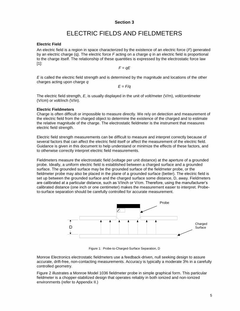
Fieldmeters measure the electrostatic field (voltage per unit distance) at the aperture of a grounded probe. Ideally, a uniform electric field is established between a charged surface and a grounded surface. The grounded surface may be the grounded surface of the fieldmeter probe, or the fieldmeter probe may also be placed in the plane of a grounded surface (better). The electric field is set up between the grounded surface and the charged surface some distance, D, away. Fieldmeters are calibrated at a particular distance, such as V/inch or V/cm. Therefore, using the manufacturer’s calibrated distance (one inch or one centimeter) makes the measurement easier to interpret. Probe-to-surface separation should be carefully controlled for accurate measurement.
Figure 1: Probe-to-Charged-Surface Separation, D
Monroe Electronics electrostatic fieldmeters use a feedback-driven, null seeking design to assure accurate, drift-free, non-contacting measurements. Accuracy is typically a moderate 3% in a carefully controlled geometry.
Figure 2 illustrates a Monroe Model 1036 fieldmeter probe in simple graphical form. This particular fieldmeter is a chopper-stabilized design that operates reliably in both ionized and non-ionized environments (refer to Appendix II.)
D
Probe
Charged Surface
6
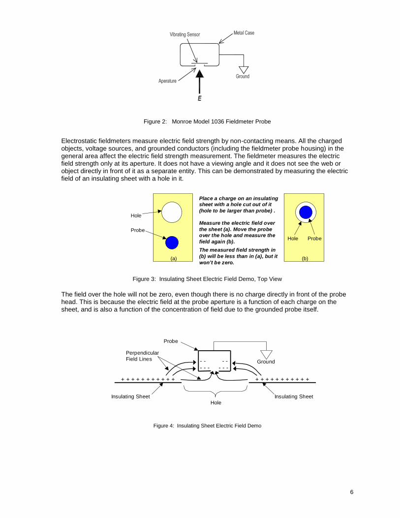
Figure 2: Monroe Model 1036 Fieldmeter Probe
Electrostatic fieldmeters measure electric field strength by non-contacting means. All the charged objects, voltage sources, and grounded conductors (including the fieldmeter probe housing) in the general area affect the electric field strength measurement. The fieldmeter measures the electric field strength only at its aperture. It does not have a viewing angle and it does not see the web or object directly in front of it as a separate entity. This can be demonstrated by measuring the electric field of an insulating sheet with a hole in it.
Figure 3: Insulating Sheet Electric Field Demo, Top View The field over the hole will not be zero, even though there is no charge directly in front of the probe head. This is because the electric field at the probe aperture is a function of each charge on the sheet, and is also a function of the concentration of field due to the grounded probe itself.
Figure 4: Insulating Sheet Electric Field Demo
Place a charge on an insulating sheet with a hole cut out of it
(hole to be larger than probe) .
Measure the electric field over
the sheet (a). Move the probe over the hole and measure the
field again (b).
The measured field strength in
(b) will be less than in (a), but it
won’t be zero.
Probe
Probe Hole
Hole
(a) (b)
Insulating Sheet
+ + + + + + + + + + + + + + + + + + + + + +
Ground
- - - - -
- - - - -
Perpendicular Field Lines
Probe
Insulating Sheet Hole
7
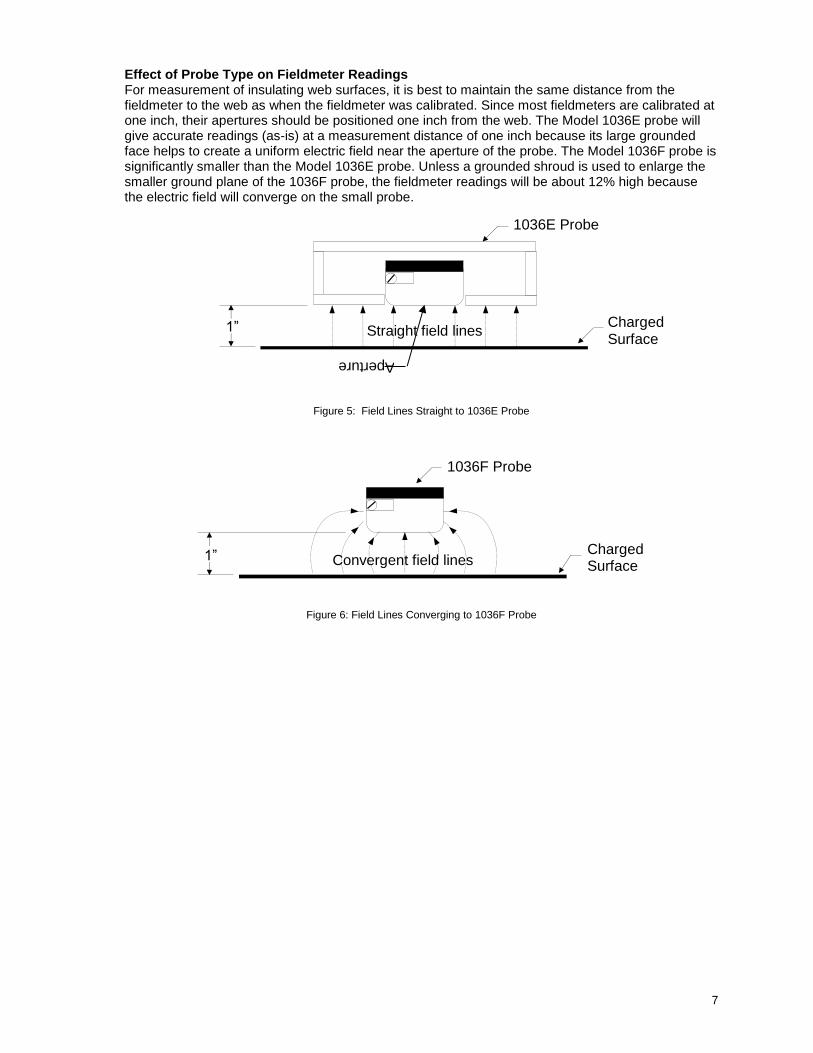
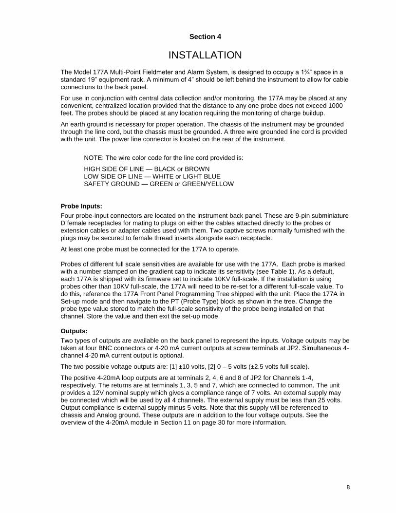
Effect of Probe Type on Fieldmeter Readings For measurement of insulating web surfaces, it is best to maintain the same distance from the fieldmeter to the web as when the fieldmeter was calibrated. Since most fieldmeters are calibrated at one inch, their apertures should be positioned one inch from the web. The Model 1036E probe will give accurate readings (as-is) at a measurement distance of one inch because its large grounded face helps to create a uniform electric field near the aperture of the probe. The Model 1036F probe is significantly smaller than the Model 1036E probe. Unless a grounded shroud is used to enlarge the smaller ground plane of the 1036F probe, the fieldmeter readings will be about 12% high because the electric field will converge on the small probe.
Figure 5: Field Lines Straight to 1036E Probe
Figure 6: Field Lines Converging to 1036F Probe
Convergent field lines
1036F Probe
Charged Surface
1”
Straight field lines
1036E Probe
Charged Surface
1”
Aperture
8
Section 4
INSTALLATION
The Model 177A Multi-Point Fieldmeter and Alarm System, is designed to occupy a 1¾” space in a standard 19” equipment rack. A minimum of 4” should be left behind the instrument to allow for cable connections to the back panel.
For use in conjunction with central data collection and/or monitoring, the 177A may be placed at any convenient, centralized location provided that the distance to any one probe does not exceed 1000 feet. The probes should be placed at any location requiring the monitoring of charge buildup.
An earth ground is necessary for proper operation. The chassis of the instrument may be grounded through the line cord, but the chassis must be grounded. A three wire grounded line cord is provided with the unit. The power line connector is located on the rear of the instrument.
NOTE: The wire color code for the line cord provided is:
HIGH SIDE OF LINE — BLACK or BROWN LOW SIDE OF LINE — WHITE or LIGHT BLUE SAFETY GROUND — GREEN or GREEN/YELLOW
Probe Inputs:
Four probe-input connectors are located on the instrument back panel. These are 9-pin subminiature D female receptacles for mating to plugs on either the cables attached directly to the probes or extension cables or adapter cables used with them. Two captive screws normally furnished with the plugs may be secured to female thread inserts alongside each receptacle.
At least one probe must be connected for the 177A to operate. Probes of different full scale sensitivities are available for use with the 177A. Each probe is marked with a number stamped on the gradient cap to indicate its sensitivity (see Table 1). As a default, each 177A is shipped with its firmware set to indicate 10KV full-scale. If the installation is using probes other than 10KV full-scale, the 177A will need to be re-set for a different full-scale value. To do this, reference the 177A Front Panel Programming Tree shipped with the unit. Place the 177A in Set-up mode and then navigate to the PT (Probe Type) block as shown in the tree. Change the probe type value stored to match the full-scale sensitivity of the probe being installed on that channel. Store the value and then exit the set-up mode. Outputs:
Two types of outputs are available on the back panel to represent the inputs. Voltage outputs may be taken at four BNC connectors or 4-20 mA current outputs at screw terminals at JP2. Simultaneous 4-channel 4-20 mA current output is optional.
The two possible voltage outputs are: [1] ±10 volts, [2] 0 – 5 volts (±2.5 volts full scale).
The positive 4-20mA loop outputs are at terminals 2, 4, 6 and 8 of JP2 for Channels 1-4, respectively. The returns are at terminals 1, 3, 5 and 7, which are connected to common. The unit provides a 12V nominal supply which gives a compliance range of 7 volts. An external supply may be connected which will be used by all 4 channels. The external supply must be less than 25 volts. Output compliance is external supply minus 5 volts. Note that this supply will be referenced to chassis and Analog ground. These outputs are in addition to the four voltage outputs. See the overview of the 4-20mA module in Section 11 on page 30 for more information.
9
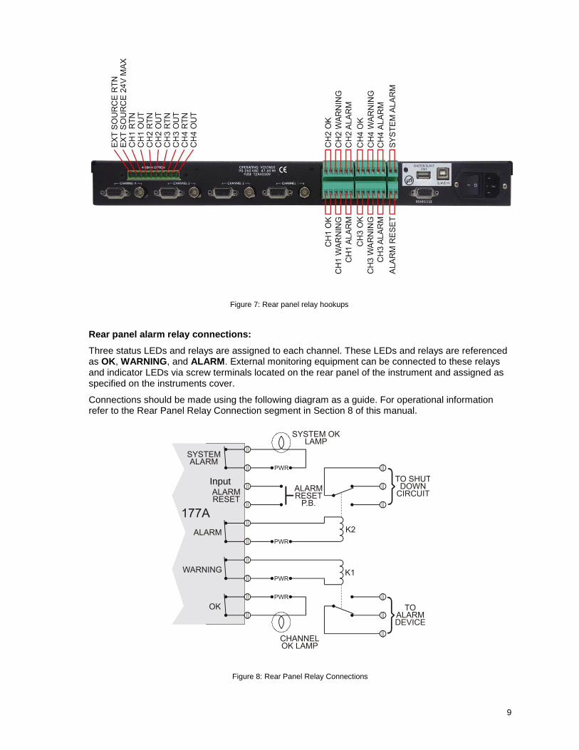
Rear panel alarm relay connections:
Three status LEDs and relays are assigned to each channel. These LEDs and relays are referenced as OK, WARNING, and ALARM. External monitoring equipment can be connected to these relays and indicator LEDs via screw terminals located on the rear panel of the instrument and assigned as specified on the instruments cover.
Connections should be made using the following diagram as a guide. For operational information refer to the Rear Panel Relay Connection segment in Section 8 of this manual.
Input
Figure 8: Rear Panel Relay Connections
Figure 7: Rear panel relay hookups
10
Section 5
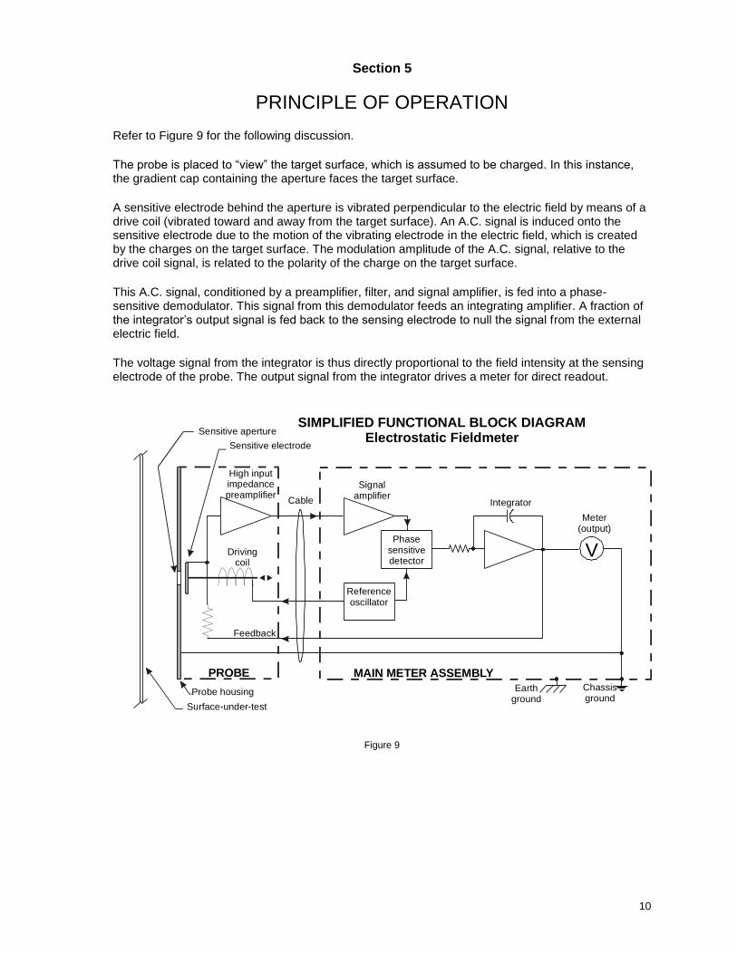
PRINCIPLE OF OPERATION Refer to Figure 9 for the following discussion.
The probe is placed to “view” the target surface, which is assumed to be charged. In this instance, the gradient cap containing the aperture faces the target surface.
A sensitive electrode behind the aperture is vibrated perpendicular to the electric field by means of a drive coil (vibrated toward and away from the target surface). An A.C. signal is induced onto the sensitive electrode due to the motion of the vibrating electrode in the electric field, which is created by the charges on the target surface. The modulation amplitude of the A.C. signal, relative to the drive coil signal, is related to the polarity of the charge on the target surface.
This A.C. signal, conditioned by a preamplifier, filter, and signal amplifier, is fed into a phase-sensitive demodulator. This signal from this demodulator feeds an integrating amplifier. A fraction of the integrator’s output signal is fed back to the sensing electrode to null the signal from the external electric field.
The voltage signal from the integrator is thus directly proportional to the field intensity at the sensing electrode of the probe. The output signal from the integrator drives a meter for direct readout.
Figure 9
V
Integrator
Phasesensitivedetector
Referenceoscillator
Signalamplifier
Meter(output)
Cable
High inputimpedancepreamplifier
Sensitive electrode
Sensitive aperture
PROBE MAIN METER ASSEMBLY
SIMPLIFIED FUNCTIONAL BLOCK DIAGRAMElectrostatic Fieldmeter
Chassisground
Earthground
Drivingcoil
Feedback
Probe housing
Surface-under-test
11
Section 6
Using 1036E and 1036F Sensors
General
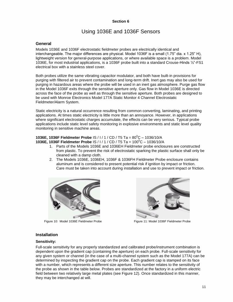
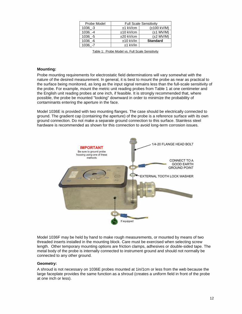
Models 1036E and 1036F electrostatic fieldmeter probes are electrically identical and interchangeable. The major differences are physical. Model 1036F is a small (1.75” dia. x 1.25” H), lightweight version for general-purpose applications, or where available space is a problem. Model 1036E, for most industrial applications, is a 1036F probe built into a standard Crouse-Hinds ½”-FS1 electrical box with a stainless steel cover. Both probes utilize the same vibrating capacitor modulator, and both have built-in provisions for purging with filtered air to prevent contamination and long-term drift. Inert gas may also be used for purging in hazardous areas where the probe will be used in an inert gas atmosphere. Purge gas flow in the Model 1036F exits through the sensitive aperture only. Gas flow in Model 1036E is directed across the face of the probe as well as through the sensitive aperture. Both probes are designed to be used with Monroe Electronics Model 177A Static Monitor 4 Channel Electrostatic Fieldmeter/Alarm System. Static electricity is a natural occurrence resulting from common converting, laminating, and printing applications. At times static electricity is little more than an annoyance. However, in applications where significant electrostatic charges accumulate, the effects can be very serious. Typical probe applications include static level safety monitoring in explosive environments and static level quality monitoring in sensitive machine areas.
1036E, 1036F Fieldmeter Probe IS / I / 1 / CD / T5 Ta = 80
0C – 1036/10/A
1036E, 1036F Fieldmeter Probe IS / I / 1 / CD / T5 Ta = 1000C – 1036/10/A
1. Parts of the Models 1036E and 1036EH Fieldmeter probe enclosures are constructed from plastic. To prevent the risk of electrostatic sparking the plastic surface shall only be cleaned with a damp cloth.
2. The Models 1036E, 1036EH, 1036F & 1036FH Fieldmeter Probe enclosure contains aluminum and is considered to present potential risk if ignition by impact or friction. Care must be taken into account during installation and use to prevent impact or friction.
Figure 10: Model 1036E Fieldmeter Probe Figure 11: Model 1036F Fieldmeter Probe
Installation
Sensitivity:
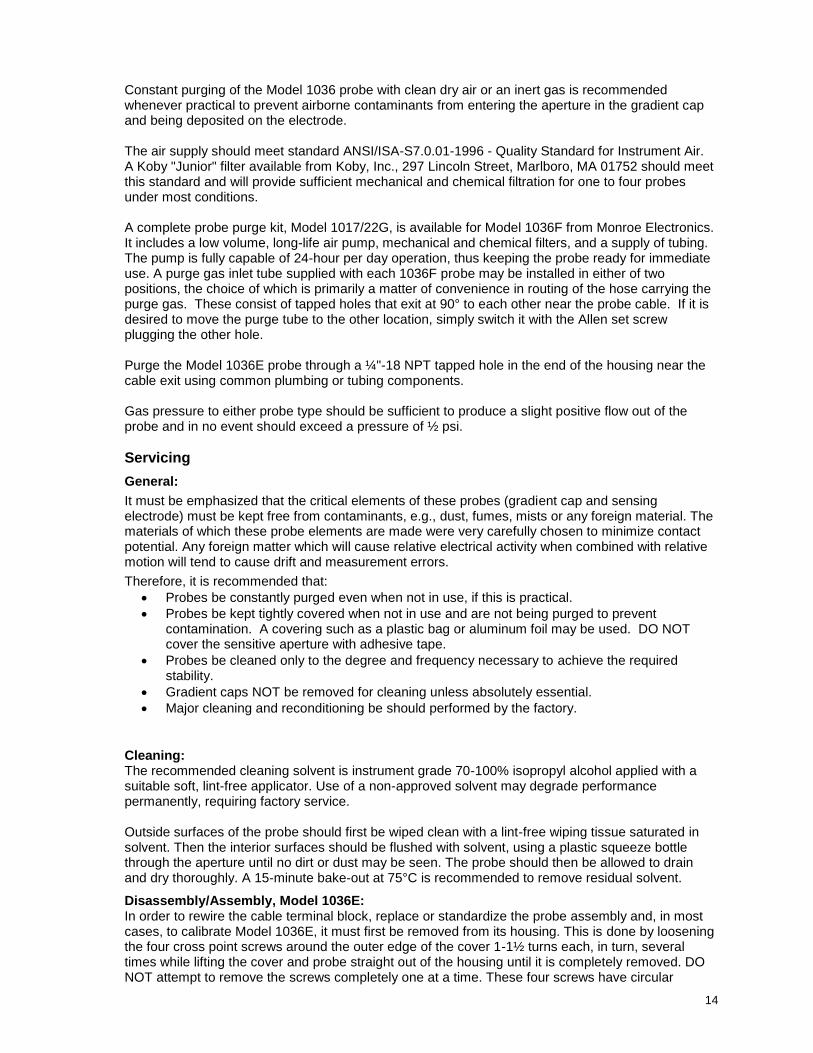
Full-scale sensitivity for any properly standardized and calibrated probe/instrument combination is dependent upon the gradient cap (containing the aperture) on each probe. Full-scale sensitivity for any given system or channel (in the case of a multi-channel system such as the Model 177A) can be determined by inspecting the gradient cap on the probe. Each gradient cap is stamped on its face with a number, which represents a different size aperture. This number relates to the sensitivity of the probe as shown in the table below. Probes are standardized at the factory in a uniform electric field between two relatively large metal plates (see Figure 12). Once standardized in this manner, they may be interchanged at will.
12
Probe Model Full Scale Sensitivity
1036_-3 ±1 kV/cm (±100 kV/M)
1036_-4 ±10 kV/cm (±1 MV/M)
1036_-5 ±20 kV/cm (±2 MV/M)
1036_-6 ±10 kV/in Standard
1036_-7 ±1 kV/in
Table 1: Probe Model vs. Full Scale Sensitivity
Mounting:
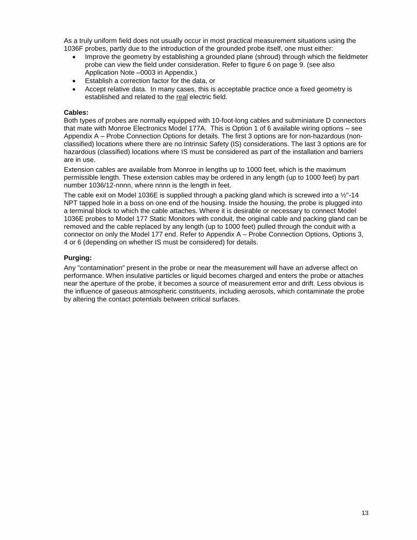
Probe mounting requirements for electrostatic field determinations will vary somewhat with the nature of the desired measurement. In general, it is best to mount the probe as near as practical to the surface being monitored, as long as the input signal remains less than the full-scale sensitivity of the probe. For example, mount the metric unit reading probes from Table 1 at one centimeter and the English unit reading probes at one inch, if feasible. It is strongly recommended that, where possible, the probe be mounted "looking" downward in order to minimize the probability of contaminants entering the aperture in the face. Model 1036E is provided with two mounting flanges. The case should be electrically connected to ground. The gradient cap (containing the aperture) of the probe is a reference surface with its own ground connection. Do not make a separate ground connection to this surface. Stainless steel hardware is recommended as shown for this connection to avoid long-term corrosion issues.
Model 1036F may be held by hand to make rough measurements, or mounted by means of two threaded inserts installed in the mounting block. Care must be exercised when selecting screw length. Other temporary mounting options are friction clamps, adhesives or double-sided tape. The metal body of the probe is internally connected to instrument ground and should not normally be connected to any other ground.
Geometry:
A shroud is not necessary on 1036E probes mounted at 1in/1cm or less from the web because the large faceplate provides the same function as a shroud (creates a uniform field in front of the probe at one inch or less).
13
As a truly uniform field does not usually occur in most practical measurement situations using the 1036F probes, partly due to the introduction of the grounded probe itself, one must either:
Improve the geometry by establishing a grounded plane (shroud) through which the fieldmeter probe can view the field under consideration. Refer to figure 6 on page 9. (see also Application Note –0003 in Appendix.)
Establish a correction factor for the data, or
Accept relative data. In many cases, this is acceptable practice once a fixed geometry is established and related to the real electric field.
Cables: Both types of probes are normally equipped with 10-foot-long cables and subminiature D connectors that mate with Monroe Electronics Model 177A. This is Option 1 of 6 available wiring options – see Appendix A – Probe Connection Options for details. The first 3 options are for non-hazardous (non-classified) locations where there are no Intrinsic Safety (IS) considerations. The last 3 options are for hazardous (classified) locations where IS must be considered as part of the installation and barriers are in use.
Extension cables are available from Monroe in lengths up to 1000 feet, which is the maximum permissible length. These extension cables may be ordered in any length (up to 1000 feet) by part number 1036/12-nnnn, where nnnn is the length in feet.
The cable exit on Model 1036E is supplied through a packing gland which is screwed into a ½"-14 NPT tapped hole in a boss on one end of the housing. Inside the housing, the probe is plugged into a terminal block to which the cable attaches. Where it is desirable or necessary to connect Model 1036E probes to Model 177 Static Monitors with conduit, the original cable and packing gland can be removed and the cable replaced by any length (up to 1000 feet) pulled through the conduit with a connector on only the Model 177 end. Refer to Appendix A – Probe Connection Options, Options 3, 4 or 6 (depending on whether IS must be considered) for details. Purging:
Any "contamination" present in the probe or near the measurement will have an adverse affect on performance. When insulative particles or liquid becomes charged and enters the probe or attaches near the aperture of the probe, it becomes a source of measurement error and drift. Less obvious is the influence of gaseous atmospheric constituents, including aerosols, which contaminate the probe by altering the contact potentials between critical surfaces.
14
Constant purging of the Model 1036 probe with clean dry air or an inert gas is recommended whenever practical to prevent airborne contaminants from entering the aperture in the gradient cap and being deposited on the electrode. The air supply should meet standard ANSI/ISA-S7.0.01-1996 - Quality Standard for Instrument Air. A Koby "Junior" filter available from Koby, Inc., 297 Lincoln Street, Marlboro, MA 01752 should meet this standard and will provide sufficient mechanical and chemical filtration for one to four probes under most conditions. A complete probe purge kit, Model 1017/22G, is available for Model 1036F from Monroe Electronics. It includes a low volume, long-life air pump, mechanical and chemical filters, and a supply of tubing. The pump is fully capable of 24-hour per day operation, thus keeping the probe ready for immediate use. A purge gas inlet tube supplied with each 1036F probe may be installed in either of two positions, the choice of which is primarily a matter of convenience in routing of the hose carrying the purge gas. These consist of tapped holes that exit at 90° to each other near the probe cable. If it is desired to move the purge tube to the other location, simply switch it with the Allen set screw plugging the other hole. Purge the Model 1036E probe through a ¼"-18 NPT tapped hole in the end of the housing near the cable exit using common plumbing or tubing components. Gas pressure to either probe type should be sufficient to produce a slight positive flow out of the probe and in no event should exceed a pressure of ½ psi.
Servicing
General:
It must be emphasized that the critical elements of these probes (gradient cap and sensing electrode) must be kept free from contaminants, e.g., dust, fumes, mists or any foreign material. The materials of which these probe elements are made were very carefully chosen to minimize contact potential. Any foreign matter which will cause relative electrical activity when combined with relative motion will tend to cause drift and measurement errors.
Therefore, it is recommended that:
Probes be constantly purged even when not in use, if this is practical.
Probes be kept tightly covered when not in use and are not being purged to prevent contamination. A covering such as a plastic bag or aluminum foil may be used. DO NOT cover the sensitive aperture with adhesive tape.
Probes be cleaned only to the degree and frequency necessary to achieve the required stability.
Gradient caps NOT be removed for cleaning unless absolutely essential.
Major cleaning and reconditioning be should performed by the factory.
Cleaning: The recommended cleaning solvent is instrument grade 70-100% isopropyl alcohol applied with a suitable soft, lint-free applicator. Use of a non-approved solvent may degrade performance permanently, requiring factory service. Outside surfaces of the probe should first be wiped clean with a lint-free wiping tissue saturated in solvent. Then the interior surfaces should be flushed with solvent, using a plastic squeeze bottle through the aperture until no dirt or dust may be seen. The probe should then be allowed to drain and dry thoroughly. A 15-minute bake-out at 75°C is recommended to remove residual solvent.
Disassembly/Assembly, Model 1036E: In order to rewire the cable terminal block, replace or standardize the probe assembly and, in most cases, to calibrate Model 1036E, it must first be removed from its housing. This is done by loosening the four cross point screws around the outer edge of the cover 1-1½ turns each, in turn, several times while lifting the cover and probe straight out of the housing until it is completely removed. DO NOT attempt to remove the screws completely one at a time. These four screws have circular
15
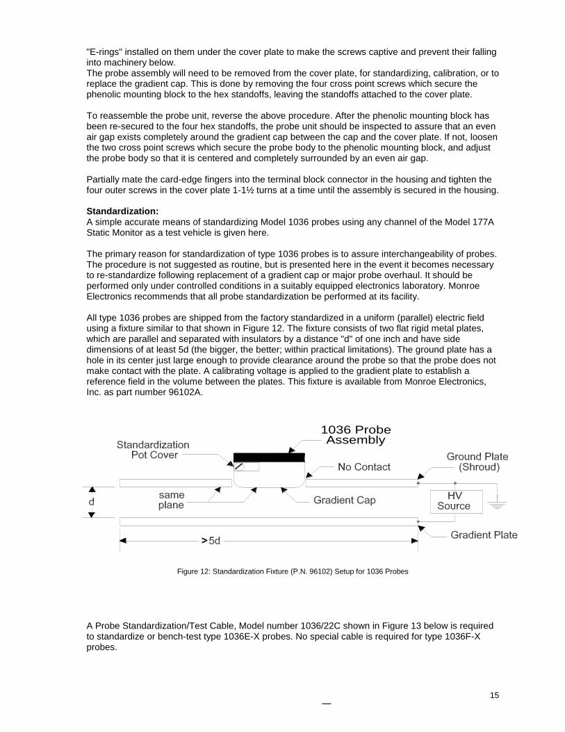
"E-rings" installed on them under the cover plate to make the screws captive and prevent their falling into machinery below. The probe assembly will need to be removed from the cover plate, for standardizing, calibration, or to replace the gradient cap. This is done by removing the four cross point screws which secure the phenolic mounting block to the hex standoffs, leaving the standoffs attached to the cover plate. To reassemble the probe unit, reverse the above procedure. After the phenolic mounting block has been re-secured to the four hex standoffs, the probe unit should be inspected to assure that an even air gap exists completely around the gradient cap between the cap and the cover plate. If not, loosen the two cross point screws which secure the probe body to the phenolic mounting block, and adjust the probe body so that it is centered and completely surrounded by an even air gap. Partially mate the card-edge fingers into the terminal block connector in the housing and tighten the four outer screws in the cover plate 1-1½ turns at a time until the assembly is secured in the housing. Standardization: A simple accurate means of standardizing Model 1036 probes using any channel of the Model 177A Static Monitor as a test vehicle is given here. The primary reason for standardization of type 1036 probes is to assure interchangeability of probes. The procedure is not suggested as routine, but is presented here in the event it becomes necessary to re-standardize following replacement of a gradient cap or major probe overhaul. It should be performed only under controlled conditions in a suitably equipped electronics laboratory. Monroe Electronics recommends that all probe standardization be performed at its facility. All type 1036 probes are shipped from the factory standardized in a uniform (parallel) electric field using a fixture similar to that shown in Figure 12. The fixture consists of two flat rigid metal plates, which are parallel and separated with insulators by a distance "d" of one inch and have side dimensions of at least 5d (the bigger, the better; within practical limitations). The ground plate has a hole in its center just large enough to provide clearance around the probe so that the probe does not make contact with the plate. A calibrating voltage is applied to the gradient plate to establish a reference field in the volume between the plates. This fixture is available from Monroe Electronics, Inc. as part number 96102A.
Figure 12: Standardization Fixture (P.N. 96102) Setup for 1036 Probes
A Probe Standardization/Test Cable, Model number 1036/22C shown in Figure 13 below is required to standardize or bench-test type 1036E-X probes. No special cable is required for type 1036F-X probes.
1036 ProbeAssembly
16
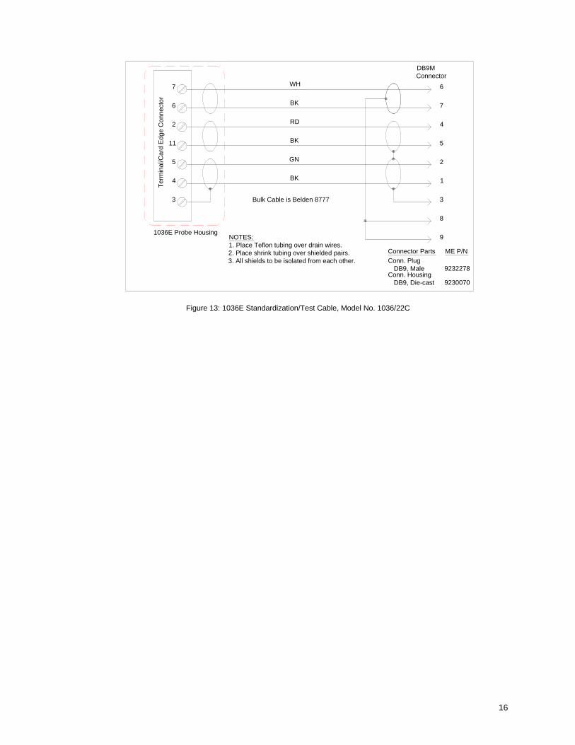
Figure 13: 1036E Standardization/Test Cable, Model No. 1036/22C
Te
rmin
al/C
ard
Ed
ge
Co
nn
ecto
r
WH
BK
RD
BK
GN
BK
6
5
3
4
11
2
7
1036E Probe Housing
Bulk Cable is Belden 8777
NOTES:
1. Place Teflon tubing over drain wires.
2. Place shrink tubing over shielded pairs.
3. All shields to be isolated from each other.
Conn. Housing
DB9, Die-cast
Connector Parts
Conn. Plug
DB9, Male
9230070
9232278
ME P/N
9
8
DB9M
Connector
7
2
3
1
5
4
6
17
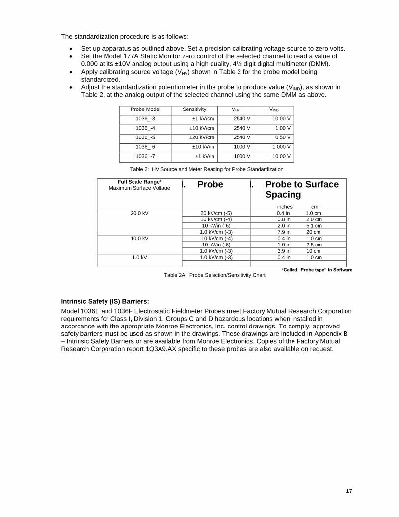
The standardization procedure is as follows:
Set up apparatus as outlined above. Set a precision calibrating voltage source to zero volts.
Set the Model 177A Static Monitor zero control of the selected channel to read a value of 0.000 at its ±10V analog output using a high quality, 4½ digit digital multimeter (DMM).
Apply calibrating source voltage (VHV) shown in Table 2 for the probe model being standardized.
Adjust the standardization potentiometer in the probe to produce value (VIND), as shown in Table 2, at the analog output of the selected channel using the same DMM as above.
Probe Model Sensitivity VHV VIND
1036_-3 ±1 kV/cm 2540 V 10.00 V
1036_-4 ±10 kV/cm 2540 V 1.00 V
1036_-5 ±20 kV/cm 2540 V 0.50 V
1036_-6 ±10 kV/in 1000 V 1.000 V
1036_-7 ±1 kV/in 1000 V 10.00 V
Table 2: HV Source and Meter Reading for Probe Standardization
Full Scale Range* Maximum Surface Voltage I. Probe II. Probe to Surface
Spacing inches cm.
20.0 kV 20 kV/cm (-5) 0.4 in 1.0 cm
10 kV/cm (-4) 0.8 in 2.0 cm
10 kV/in (-6) 2.0 in 5.1 cm
1.0 kV/cm (-3) 7.9 in 20 cm
10.0 kV 10 kV/cm (-4) 0.4 in 1.0 cm
10 kV/in (-6) 1.0 in 2.5 cm
1.0 kV/cm (-3) 3.9 in 10 cm.
1.0 kV 1.0 kV/cm (-3) 0.4 in 1.0 cm
*Called “Probe type” in Software
Table 2A: Probe Selection/Sensitivity Chart
Intrinsic Safety (IS) Barriers:
Model 1036E and 1036F Electrostatic Fieldmeter Probes meet Factory Mutual Research Corporation requirements for Class I, Division 1, Groups C and D hazardous locations when installed in accordance with the appropriate Monroe Electronics, Inc. control drawings. To comply, approved safety barriers must be used as shown in the drawings. These drawings are included in Appendix B – Intrinsic Safety Barriers or are available from Monroe Electronics. Copies of the Factory Mutual Research Corporation report 1Q3A9.AX specific to these probes are also available on request.
18
Section 7
Typical Setup
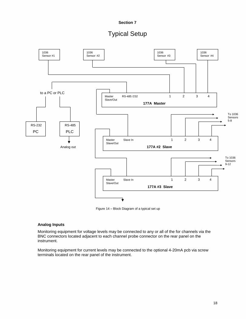
Analog Inputs
Monitoring equipment for voltage levels may be connected to any or all of the for channels via the BNC connectors located adjacent to each channel probe connector on the rear panel on the instrument. Monitoring equipment for current levels may be connected to the optional 4-20mA pcb via screw terminals located on the rear panel of the instrument.
To 1036 Sensors 9-12
To 1036 Sensors 5-8
1036 Sensor #2
1036 Sensor #4
1036 Sensor #3
1036 Sensor #1
Master RS-485 /232 1 2 3 4 Slave/Out
177A Master
RS-232
PC
Master Slave In 1 2 3 4 Slave/Out
177A #2 Slave
Master Slave In 1 2 3 4 Slave/Out
177A #3 Slave
Figure 14 – Block Diagram of a typical set up
RS-485
PLC
to a PC or PLC
Analog out
19
Section 8
OPERATION
Front Panel Features
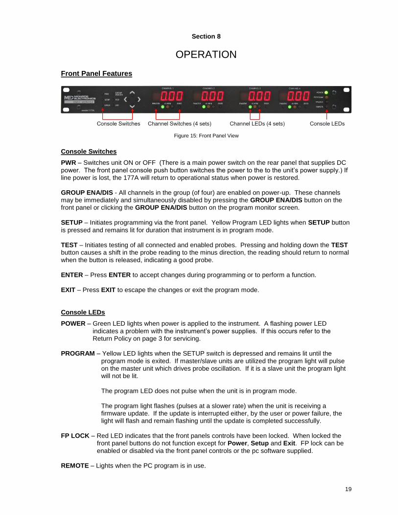
Figure 15: Front Panel View
Console Switches
PWR – Switches unit ON or OFF (There is a main power switch on the rear panel that supplies DC power. The front panel console push button switches the power to the to the unit’s power supply.) If line power is lost, the 177A will return to operational status when power is restored. GROUP ENA/DIS - All channels in the group (of four) are enabled on power-up. These channels may be immediately and simultaneously disabled by pressing the GROUP ENA/DIS button on the front panel or clicking the GROUP ENA/DIS button on the program monitor screen. SETUP – Initiates programming via the front panel. Yellow Program LED lights when SETUP button is pressed and remains lit for duration that instrument is in program mode. TEST – Initiates testing of all connected and enabled probes. Pressing and holding down the TEST button causes a shift in the probe reading to the minus direction, the reading should return to normal when the button is released, indicating a good probe. ENTER – Press ENTER to accept changes during programming or to perform a function. EXIT – Press EXIT to escape the changes or exit the program mode. Console LEDs
POWER – Green LED lights when power is applied to the instrument. A flashing power LED indicates a problem with the instrument’s power supplies. If this occurs refer to the Return Policy on page 3 for servicing.
PROGRAM – Yellow LED lights when the SETUP switch is depressed and remains lit until the
program mode is exited. If master/slave units are utilized the program light will pulse on the master unit which drives probe oscillation. If it is a slave unit the program light will not be lit.
The program LED does not pulse when the unit is in program mode.
The program light flashes (pulses at a slower rate) when the unit is receiving a firmware update. If the update is interrupted either, by the user or power failure, the light will flash and remain flashing until the update is completed successfully.
FP LOCK – Red LED indicates that the front panels controls have been locked. When locked the
front panel buttons do not function except for Power, Setup and Exit. FP lock can be enabled or disabled via the front panel controls or the pc software supplied.
REMOTE – Lights when the PC program is in use.

20
Rear Panel Relay Connections Three status LEDs and relays are assigned to each channel. These LEDs and relays are referenced as OK, WARNING, and ALARM. External monitoring equipment can be connected to these via screw terminals located on the rear panel of the instrument. Connections are specified in Figure 7 on page 10 and on the instrument’s cover.
Three modes of operation are available:
Alarm Mode - Latching
Under normal operating conditions (i.e. the monitored static level is less than the preset warning and alarm levels) all three relays are energized initiating a contact closure. The green or OK status LED is blinking while the yellow or WARNING and red or ALARM status LEDs are not lit.
When static levels reach the preset Warning level and the preset Alarm Delay has expired (refer to Program Setup in Section 9 for details) the Warning relay will open and the Warning LED will light. The OK LED will continue to blink. Whenever the instrument achieves Warning mode it will stay in that condition until the problem is corrected or the static level falls to less than the preset warning.
When static levels reach the preset Alarm level and the preset Alarm Delay has expired (refer to Program Setup in Section 9 for details) the Alarm relay will open and the Alarm LED will light. The OK LED will continue to blink and the Warning LED remains lit as well.
System Alarm - Upon realization of an alarm condition the System Alarm relay will open. Upon opening the System button on the Monitor screen on your pc will flash red.
Whenever the instrument achieves Alarm mode it will stay in that condition until the problem is corrected and the instrument is manually reset by toggling the channel’s ENA/DIS button on the instrument console or via the pc program provided or by momentarily shorting the Alarm Reset terminals on the back panel.
Alarm Mode – Non-Latching
Under normal operating conditions (i.e. the monitored static level is less than the preset warning and alarm levels) all three relays are energized initiating a contact closure. The green or OK status LED is blinking while the yellow or WARNING and red or ALARM status LEDs are not lit.
When static levels reach the preset Warning level and the preset Alarm Delay has expired (refer to Program Setup in Section 9 for details) the Warning relay will open and the Warning LED will light. The OK LED will continue to blink. Whenever the instrument achieves Warning mode it will stay in that condition until the problem is corrected or the static level falls to less than the preset warning level.
When static levels reach the preset Alarm level and the preset Alarm Delay has expired (refer to Program Setup in Section 9 for details) the Alarm relay will open and the Alarm LED will light. The OK LED will continue to blink and the Warning LED remains lit as well.
System Alarm - Upon realization of an alarm condition the System Alarm relay will open. Upon opening the System button on the Monitor screen on your pc will flash red.
Whenever the instrument achieves Alarm mode it will stay it that condition until the static level falls to less than the preset warning level resetting to normal operation.
Non-Alarm Mode
In non-alarm mode the alarms are disabled, the green or OK remains lit continuously. Warning and Alarm are not triggered. The instrument continues to monitor static levels regardless of operating conditions.
21
Channel Switches
ENA/DIS – Toggles the channel status between Disable / Enable / Alarm ZERO – Press and release the ZERO button to zero the channel. Display will return to pre-set zero level. The channel display to the immediate right of the channel display being zeroed will count down the pre-set zero time out. (For Channel 4 the channel display immediately to the left will count down the zero time out.) If zero level is reached within the pre-set time the channel display will read don for “done.” If the zero level is not reached within the pre-set time the display will read err for “error.”
Auto-Zero – Press and release the Zero button (< 1sec)
Manual Zero – Press and hold the zero button then push the up or down arrow buttons to adjust the zero reading
Channel LEDs
Green (left) LED – Lights and remains lit when a probe is connected and the channel is enabled (Non-Alarm mode). Lights and flashes when a probe is connected and the channel alarm is enabled. (Alram Mode: Latching and non-latching.) LED remains flashing even as the Yellow, Warning and Red, Alarm LEDs light during warning and alarm conditions. Yellow (center) LED – Lights when the pre-set voltage warning level is reached. Remains lit until voltage level drops below warning level (non-latching) or until the condition corrected and the channel is reset (Latching). Red (right) LED - Lights when the pre-set voltage alarm level is reached. Remains lit until voltage level drops below warning level (non-latching) or until the condition corrected and the channel is reset (Latching). 177A Relay and LED Functions
Initially all Ok, warning, alarm relays are closed (shorted or activated). The Ok LED is on; warning and alarm LEDs are off. Channel Ok relay is open (the green LED off) when:
The channel is enabled and has no probe.
The channel is disabled. Channel Warning relay is open (the ember LED on) when: The channel is enabled and the reading is on or above the warning level. Channel Alarm relay is open (the red LED on) when:
The channel is enabled and has no probe.
The channel is enable and the reading is on or above the alarm level. If the unit is in alarm latching mode and the reading comes back down, the relay will not close until the [Ena/Dis] or [GRP] button is depressed.
System relay is normally closed. It is open when:
One or more of the alarm relay is open.
One or more of the enabled channel has no probe.
Power supplies have failed. Power LED: On when the unit is powered up. Slow blink if power supply has failed.
22
Program LED: Normally off. It is on when doing front panel setup. Pulses on when the unit is a master. See section on master/slave operation in the User Manual.Note: if USB cable A & B are connected to the same unit, oscillator is disabled. FP Lock LED: Normally off. On when the front panel is locked. When the front panel is locked, only the [Setup] and arrow buttons work. You can unlock the unit, or browse the program setup but cannot change it.
Master/Slave out & Slave in:
Purpose
These connections provide synchronization of the probe modulators on multiple 177A’s. When probes are attached to common mountings from multiple 177A’s they can interact and cause zero shifts and low frequency oscillations without synchronization of the modulators.
Setup
Master/Slave out and Slave in connectors are provided on each 177A. The Master/Slave out either generates or passes through reference signal for synchronization. Multiple units can be daisy chained as shown in Fig 14, on page 17.. The Slave in connector accepts the Reference and forces the modulator to be synchronized with the other 177A’s. Standard USB cables with Type A/B connectors are used for interconnects. These are supplied with the 177As. Note. These connectors are NOT USB Ports
Remote LED
Normally off. Blinks when serial port is receiving.

23
Section 9
177A Software
Connecting the instrument to a PC (via RS232 serial port)
Connect the 177A to your PC using the DB9-M/F straight through cable in your accessories. Plug the male end of the cable into the RS-485/232 receptacle on the rear of the instrument. Plug the female end of the cable into the appropriate connector on your PC. Connecting via RS485
Refer to Appendix III for RS-485 connections details. Installing the Software
Insert the supplied disk into the appropriate drive. A Launch program should automatically begin running. Follow the instructions for the desired action. (i.e. to install the software click the Installation button.) If the Launch program does not automatically start refer to the following instructions:
Click on Start on your task bar and then select Run – Type the appropriate drive letter for the disk and “Install-177A-105.exe”
(i.e. - a:\ Install-177A-105.exe) on the disk and follow the subsequent instructions.
Upon completion, the program icon will be displayed in a window. Click on and drag the icon to your desktop to place a short cut there. Close the window.
Programming via PC
The software included with the 177A is designed to program, monitor and test the instrument via RS-232 or RS-485 connections using the toolbar on the program’s main screen.
Connect – Select the appropriate comport and baud rate to be used for the monitor from the drop-down menus. The baud rate should reflect the current Windows setting for this comport. Program Setup – Permits enable/disable of alarms; setting of warning and alarm levels; full scale; alarm delay; auto zero time and level; and decimal position. Four user-defined programs are available which can be set up and stored. The instrument is set to P0, the default setup program. P1 – P4 are initialized to the default settings, resetting these four programs is accomplished via the ME177A program. From the Program Setup drop-down menu:
Click on Read Setup from 177A to select program 1 – 4, or retrieve the active program. Click on Open Program on disk to retrieve a program (*.prg) from a file.
Upon retrieving a program the following window will open:
24
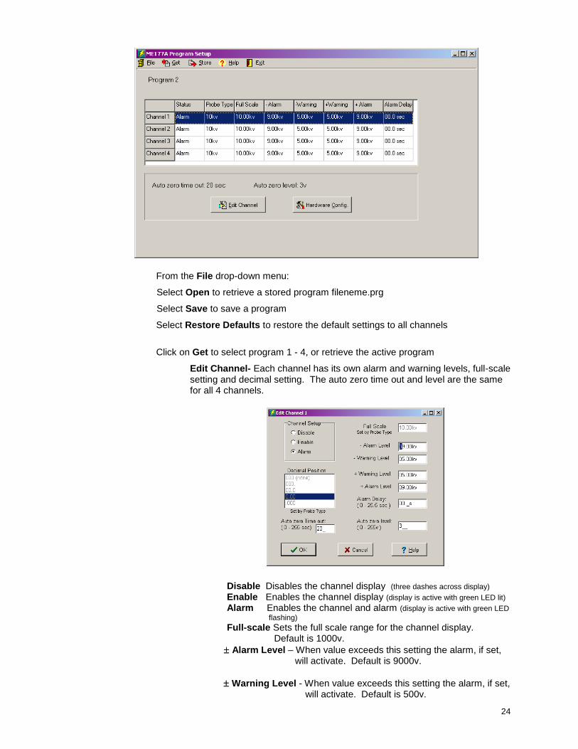
From the File drop-down menu:
Select Open to retrieve a stored program fileneme.prg
Select Save to save a program
Select Restore Defaults to restore the default settings to all channels
Click on Get to select program 1 - 4, or retrieve the active program
Edit Channel- Each channel has its own alarm and warning levels, full-scale setting and decimal setting. The auto zero time out and level are the same for all 4 channels.
Disable Disables the channel display (three dashes across display) Enable Enables the channel display (display is active with green LED lit) Alarm Enables the channel and alarm (display is active with green LED
flashing) Full-scale Sets the full scale range for the channel display. Default is 1000v.
Alarm Level – When value exceeds this setting the alarm, if set, will activate. Default is 9000v.
Warning Level - When value exceeds this setting the alarm, if set, will activate. Default is 500v.
25
Note: Alarm level must be greater than the Warning level. Full scale setting must be greater than or equal to the alarm levels. Alarm Delay – Delay time for the alarm/warning relay to open after the value exceeds the set level. Default is 0 seconds. Setting an alarm delay can prevent erroneous alarms. Auto zero – Time and Level – When the Zero button is pressed auto-zero begins. If the channel reading reaches the level within the time period, the process stops and shows done. If it times out without reaching the level, it will show error and exit out of the auto-zero process. Default time for Auto-Zero time is 20 seconds.
Default for Auto-Zero level is 3v. After editing a program you may save it to your hard drive or send it to the 177A as it’s active program. First exit the Edit Channel window by clicking on O.K., then from the Store drop-down menu:
Click on Active Program or Program 1, 2, 3, or 4 to store your program into permanent memory. If program 1, 2, 3, or 4 is set as your active program those changes will also be applied.
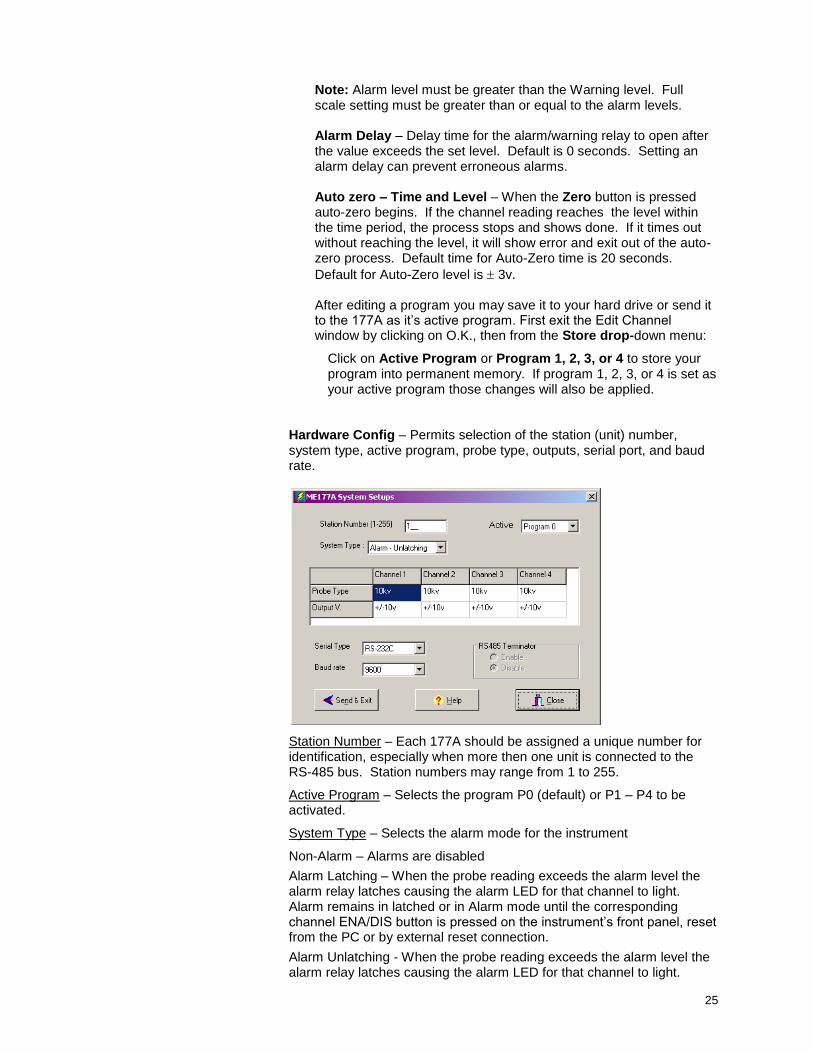
Hardware Config – Permits selection of the station (unit) number, system type, active program, probe type, outputs, serial port, and baud rate.
Station Number – Each 177A should be assigned a unique number for identification, especially when more then one unit is connected to the RS-485 bus. Station numbers may range from 1 to 255.
Active Program – Selects the program P0 (default) or P1 – P4 to be activated.
System Type – Selects the alarm mode for the instrument
Non-Alarm – Alarms are disabled
Alarm Latching – When the probe reading exceeds the alarm level the alarm relay latches causing the alarm LED for that channel to light. Alarm remains in latched or in Alarm mode until the corresponding channel ENA/DIS button is pressed on the instrument’s front panel, reset from the PC or by external reset connection.
Alarm Unlatching - When the probe reading exceeds the alarm level the alarm relay latches causing the alarm LED for that channel to light.
26
Alarm remains in latched or in Alarm mode until the probe reading falls back under the alarm level at which point the relay unlatches.
Probe Type – Must be set from the front panel set-up mode. Please refer to the Front Panel Programming Tree included on your disk.
Output Voltage - Click in a specific channel’s probe type box to set the
output voltage to either 0-5V or 10V.
Serial Type – Set serial connection type: RS-232 RS-485Half, or RS-485Full. If RS-485Full is selected and there are more then two units connected, the RS-485 Terminator should be enabled on the first and last units on the bus. Note: If the serial configuration is not properly set up the instrument will lock up. If this happens turn off the unit, disconnect the plug, reset the firmware to the correct type, restart and reconfigure the software.
Baud Rate – Set the appropriate baud rate for your system. Should be the setting used under “Connect.”
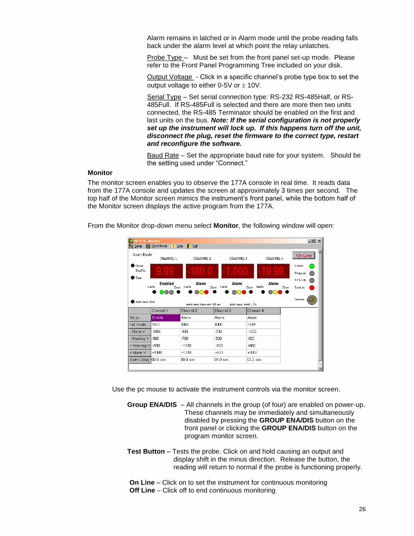
Monitor
The monitor screen enables you to observe the 177A console in real time. It reads data from the 177A console and updates the screen at approximately 3 times per second. The top half of the Monitor screen mimics the instrument’s front panel, while the bottom half of the Monitor screen displays the active program from the 177A.
From the Monitor drop-down menu select Monitor, the following window will open:
Use the pc mouse to activate the instrument controls via the monitor screen.
Group ENA/DIS – All channels in the group (of four) are enabled on power-up.
These channels may be immediately and simultaneously disabled by pressing the GROUP ENA/DIS button on the front panel or clicking the GROUP ENA/DIS button on the program monitor screen.
Test Button – Tests the probe. Click on and hold causing an output and
display shift in the minus direction. Release the button, the reading will return to normal if the probe is functioning properly.
On Line – Click on to set the instrument for continuous monitoring Off Line – Click off to end continuous monitoring

27
Ena/Dis – Toggles channel status Disable / Enable / Alarm for the corresponding channel Zero – Initiates Auto Zeroing for the corresponding channel Auto Zero Exit – Stops ongoing auto zeroing
FP Lock – Click on the button on the monitor screen or select FP
From the Front panel drop-down menu:
Lock/Unlock – Select to toggle the front panel between lock / unlock. Red LED indicates that the front panels controls have been locked. When locked the front panel buttons do not function except for Power, Setup and Exit. FP lock can be enabled or disabled via the front panel controls or the pc software supplied.
Alarm/Non-Alarm –Select to set the Alarm mode. In Alarm mode channels
can be set to enable / disable / alarm. In Non-Alarm mode channels can be set to enable / disable only.
System Diagnostic – Indicates if a system error exists. Select to test the
system. If the System icon is blinking it may be due to one or more of the following:
A channel is enabled, the alarm is set but no probe is connected.
Fix: Disable the channel or connect a probe to the channel.
A channel, with its alarm activated, has reached the alarm level. Fix: When the level has returned to its normal range toggle the channel’s ENA/DIS button to clear the alarm.
System power supply is below normal. Check power supply.
Change Password – Select to change the password. Enter the default password (Default password is 1 9 5 3 ) as prompted. Enter the new password as prompted. Upon completion, the system will confirm the password change if accepted.
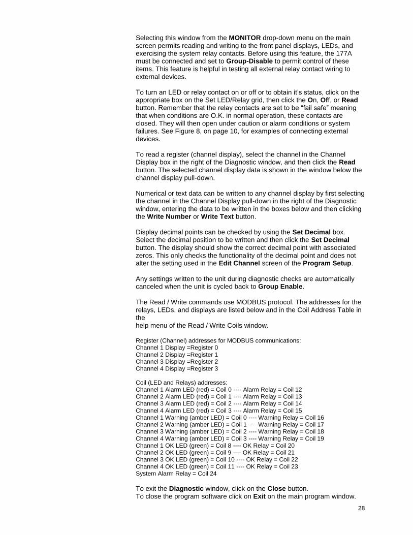
Diagnostic
From the Monitor drop-down menu select Diagnostic, the following window will open:
28
Selecting this window from the MONITOR drop-down menu on the main screen permits reading and writing to the front panel displays, LEDs, and exercising the system relay contacts. Before using this feature, the 177A must be connected and set to Group-Disable to permit control of these items. This feature is helpful in testing all external relay contact wiring to external devices.
To turn an LED or relay contact on or off or to obtain it’s status, click on the appropriate box on the Set LED/Relay grid, then click the On, Off, or Read button. Remember that the relay contacts are set to be “fail safe” meaning that when conditions are O.K. in normal operation, these contacts are closed. They will then open under caution or alarm conditions or system failures. See Figure 8, on page 10, for examples of connecting external devices. To read a register (channel display), select the channel in the Channel Display box in the right of the Diagnostic window, and then click the Read button. The selected channel display data is shown in the window below the channel display pull-down. Numerical or text data can be written to any channel display by first selecting the channel in the Channel Display pull-down in the right of the Diagnostic window, entering the data to be written in the boxes below and then clicking the Write Number or Write Text button. Display decimal points can be checked by using the Set Decimal box. Select the decimal position to be written and then click the Set Decimal button. The display should show the correct decimal point with associated zeros. This only checks the functionality of the decimal point and does not alter the setting used in the Edit Channel screen of the Program Setup. Any settings written to the unit during diagnostic checks are automatically canceled when the unit is cycled back to Group Enable.
The Read / Write commands use MODBUS protocol. The addresses for the relays, LEDs, and displays are listed below and in the Coil Address Table in the help menu of the Read / Write Coils window.
Register (Channel) addresses for MODBUS communications: Channel 1 Display =Register 0 Channel 2 Display =Register 1 Channel 3 Display =Register 2 Channel 4 Display =Register 3 Coil (LED and Relays) addresses: Channel 1 Alarm LED (red) = Coil 0 ---- Alarm Relay = Coil 12 Channel 2 Alarm LED (red) = Coil 1 ---- Alarm Relay = Coil 13 Channel 3 Alarm LED (red) = Coil 2 ---- Alarm Relay = Coil 14 Channel 4 Alarm LED (red) = Coil 3 ---- Alarm Relay = Coil 15 Channel 1 Warning (amber LED) = Coil 0 ---- Warning Relay = Coil 16 Channel 2 Warning (amber LED) = Coil 1 ---- Warning Relay = Coil 17 Channel 3 Warning (amber LED) = Coil 2 ---- Warning Relay = Coil 18 Channel 4 Warning (amber LED) = Coil 3 ---- Warning Relay = Coil 19 Channel 1 OK LED (green) = Coil 8 ---- OK Relay = Coil 20 Channel 2 OK LED (green) = Coil 9 ---- OK Relay = Coil 21 Channel 3 OK LED (green) = Coil 10 ---- OK Relay = Coil 22 Channel 4 OK LED (green) = Coil 11 ---- OK Relay = Coil 23 System Alarm Relay = Coil 24
To exit the Diagnostic window, click on the Close button. To close the program software click on Exit on the main program window.

29
Section 10
Programming via the Front Panel
A programming tree is supplied to facilitate instrument programming via the front panel. Use the programming tree in conjunction with the front panel features detailed at the beginning of Section 9 to work your way through the programming sequences. Refer to the Front Panel Program tree included on the CD provided. To enter the programming mode via the front panel press the SETUP button. Use the Up / Down / Left / Right arrow buttons to move between the displays. Press the ENTER button to accept changes or perform the function. Press the EXIT button to escape the changes or to exit SETUP mode.
30
Section 11
Optional 4 – 20 mA Module
General The optional 4-20 mA module provides 4 separate channel outputs in addition to the normal voltage outputs. All channels have a common ground. The instrument provides a 12-volt nominal supply which gives a compliance range of 7-volts. No external supply is required provided the 7-volt compliance is observed. An external supply may be connected which would be used by all four channels. The external supply must be less than 25-volts. Output compliance of the is the external supply minus 5-volts. Note that this supply will be referenced to chassis and analog ground. A termination resistor must be installed on the 4-20 mA receiving equipment and must be less than the compliance voltage, or Vcomplaince > .020 *Rin where Rin is the receiver input resistance Specifications Internal Supply: 11 volts min External Supply: 24 volts max
31
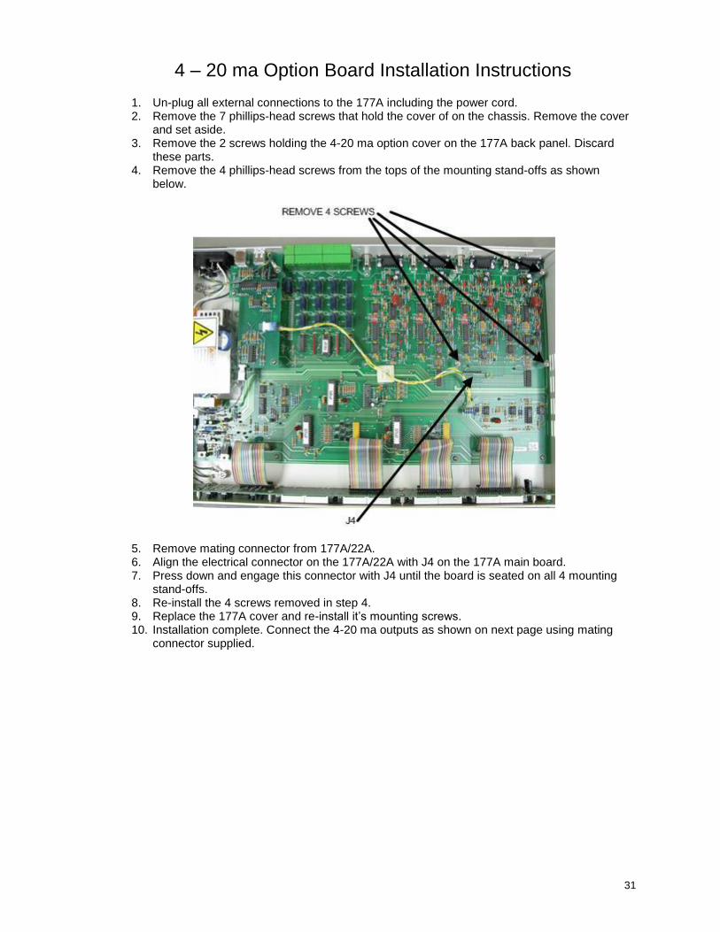
4 – 20 ma Option Board Installation Instructions
1. Un-plug all external connections to the 177A including the power cord. 2. Remove the 7 phillips-head screws that hold the cover of on the chassis. Remove the cover
and set aside. 3. Remove the 2 screws holding the 4-20 ma option cover on the 177A back panel. Discard
these parts. 4. Remove the 4 phillips-head screws from the tops of the mounting stand-offs as shown
below.
5. Remove mating connector from 177A/22A. 6. Align the electrical connector on the 177A/22A with J4 on the 177A main board. 7. Press down and engage this connector with J4 until the board is seated on all 4 mounting
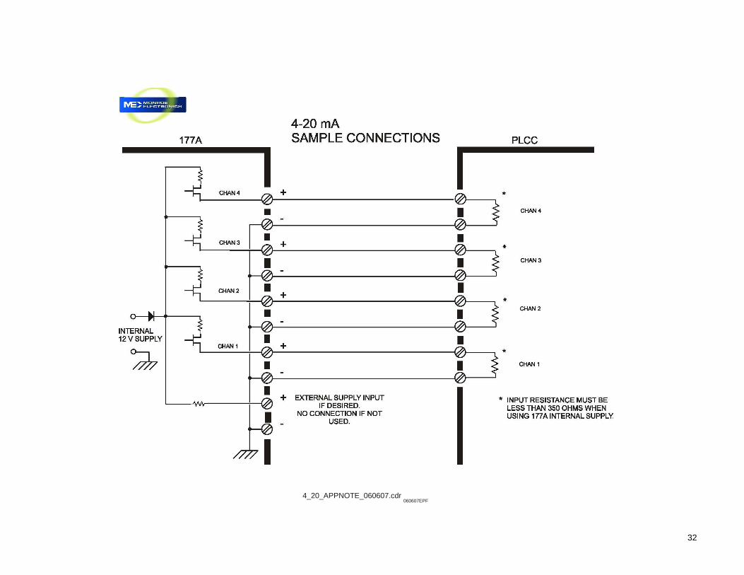
stand-offs. 8. Re-install the 4 screws removed in step 4. 9. Replace the 177A cover and re-install it’s mounting screws. 10. Installation complete. Connect the 4-20 ma outputs as shown on next page using mating
connector supplied.
32
4_20_APPNOTE_060607.cdr 060607EPF

33
Section 12
Upgrading the Firmware
From time to time firmware upgrades may be available. With units version 1.03 or higher this upgrade can be accomplished using the 177A software and obtained via download from our website, e mail, or CD. Units that are version 1.02 require reprogramming of the processor and cannot be upgraded via the 177A software. To check the version of your unit read the Channel 2 display at power up. Note: For the duration of the firmware upgrade (approximately 6 minutes) the instrument is not functional and the system is not monitoring. If you have any questions regarding firmware upgrades please contact Monroe Electronics. To initiate firmware upgrade, click on Update Firmware in the Program Setup drop-down menu. The following window will appear:
Diagram 1
Clicking on Yes will present the following window:
Clicking on OK will present the following window:
Diagram 2
34
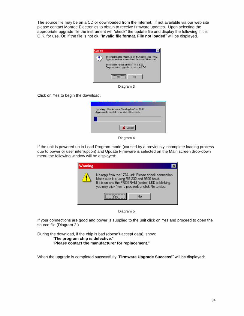
The source file may be on a CD or downloaded from the Internet. If not available via our web site please contact Monroe Electronics to obtain to receive firmware updates. Upon selecting the appropriate upgrade file the instrument will “check” the update file and display the following if it is O.K. for use. Or, if the file is not ok, “Invalid file format. File not loaded” will be displayed.
Diagram 3
Click on Yes to begin the download.
Diagram 4 If the unit is powered up in Load Program mode (caused by a previously incomplete loading process due to power or user interruption) and Update Firmware is selected on the Main screen drop-down menu the following window will be displayed:
Diagram 5
If your connections are good and power is supplied to the unit click on Yes and proceed to open the source file (Diagram 2.) During the download, if the chip is bad (doesn’t accept data), show: "The program chip is defective." "Please contact the manufacturer for replacement."
When the upgrade is completed successfully “Firmware Upgrade Success!” will be displayed:
35
APPENDIX I
PROBE CONNECTION OPTIONS
There are at least six wiring options for the Model 177A with regards to the Model 1036E or 1036F probes. The first three options are for non-hazardous (non-classified) locations where there are no Intrinsic Safety (IS) considerations. The last three options are for hazardous (classified) locations where Intrinsic Safety (IS) must be considered as part of the installation. OPTION 1: All probes (1036E or 1036F) use factory installed cables, no extension cables, no IS
considerations
Probes are normally factory equipped with ten-foot-long cables. To use or test this system, simply plug the probes into the appropriate connectors on the back of the instrument.
OPTION 2: Probes use factory-installed cables and factory supplied extension cables, no IS
considerations
Extension cables are available in lengths up to 1000 feet. The extension cable order number is 1036/12-XXXX where "XXXX" denotes the length of the cable in feet. Factory supplied extension cables will be labeled with this part number near one end.
The connector at one end mates with the connector on the end of the cable attached
to the probe and the one on the other end mates with the appropriate connector on the back of the instrument. Although it is virtually impossible to err, it is advisable to test the system "on the bench" in a confined area before permanently installing long cable runs.
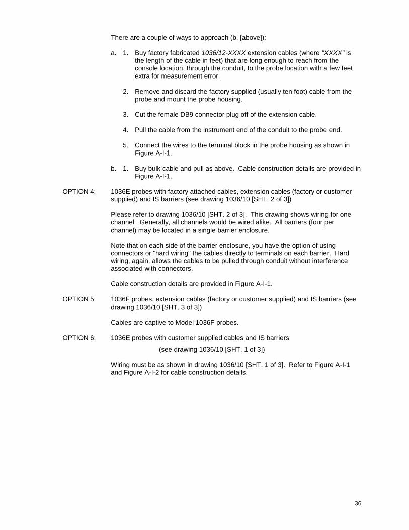
OPTION 3: 1036E probes with long customer installed cables with or without extension cables,
no IS considerations (see Figure A-I-1)
Wiring connections for customer installed 1036E probe cables for use in a non-IS installation are shown in Figure A-I-1. Model 1036E probes have terminal blocks inside their housings to which the cable wires are directly attached.
Note: 1036F probes have permanently attached cables and that this option does not apply.
As in OPTION 2, it is advisable to "bench test" the system before removing the factory-attached cables.
There are a couple of valid reasons for constructing your own cables:
a. You may be able to save money, although, in the long run,
troubleshooting may prove to be more costly than using factory-supplied cables.
or
b. It is necessary to pull the cable through a fairly long run of conduit and the connector won't fit. The largest rectangular cross sectional
dimensions of each connector are 5/8" x 11/4". The minimum conduit ID
through which this can be pulled is 13/8", although, it would be possible,
with a great deal of care, to pull up to five cables simultaneously through that ID in a smooth straight run by staggering the connectors.
36
There are a couple of ways to approach (b. [above]):
a. 1. Buy factory fabricated 1036/12-XXXX extension cables (where "XXXX" is the length of the cable in feet) that are long enough to reach from the console location, through the conduit, to the probe location with a few feet extra for measurement error.
2. Remove and discard the factory supplied (usually ten foot) cable from the
probe and mount the probe housing.
3. Cut the female DB9 connector plug off of the extension cable.
4. Pull the cable from the instrument end of the conduit to the probe end.
5. Connect the wires to the terminal block in the probe housing as shown in Figure A-I-1.
b. 1. Buy bulk cable and pull as above. Cable construction details are provided in
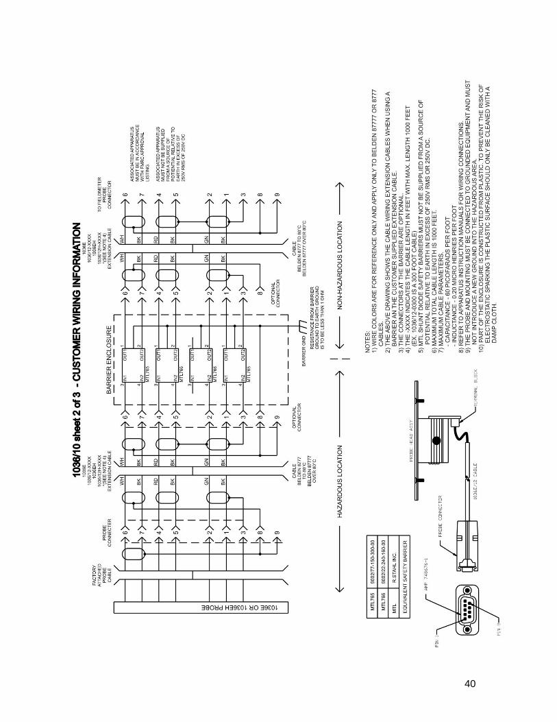
Figure A-I-1. OPTION 4: 1036E probes with factory attached cables, extension cables (factory or customer
supplied) and IS barriers (see drawing 1036/10 [SHT. 2 of 3])
Please refer to drawing 1036/10 [SHT. 2 of 3]. This drawing shows wiring for one channel. Generally, all channels would be wired alike. All barriers (four per channel) may be located in a single barrier enclosure.
Note that on each side of the barrier enclosure, you have the option of using connectors or "hard wiring" the cables directly to terminals on each barrier. Hard wiring, again, allows the cables to be pulled through conduit without interference associated with connectors.
Cable construction details are provided in Figure A-I-1.
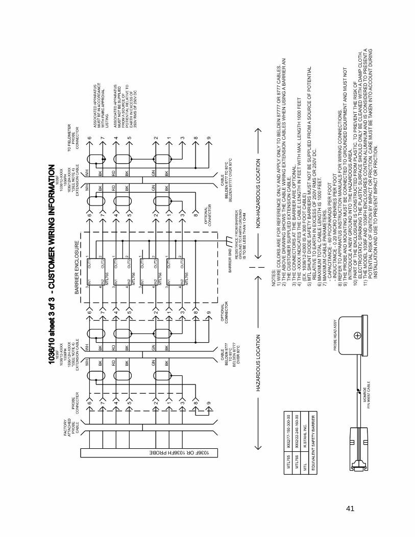
OPTION 5: 1036F probes, extension cables (factory or customer supplied) and IS barriers (see
drawing 1036/10 [SHT. 3 of 3])
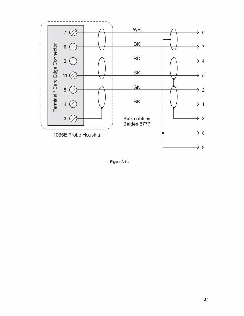
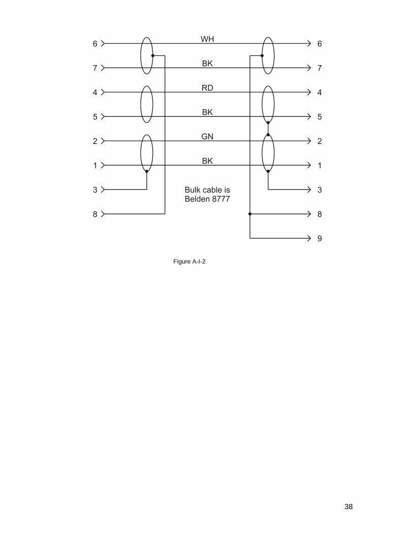
Cables are captive to Model 1036F probes. OPTION 6: 1036E probes with customer supplied cables and IS barriers
(see drawing 1036/10 [SHT. 1 of 3])
Wiring must be as shown in drawing 1036/10 [SHT. 1 of 3]. Refer to Figure A-I-1 and Figure A-I-2 for cable construction details.
37
Figure A-I-1
38
Figure A-I-2
39
40
41
42
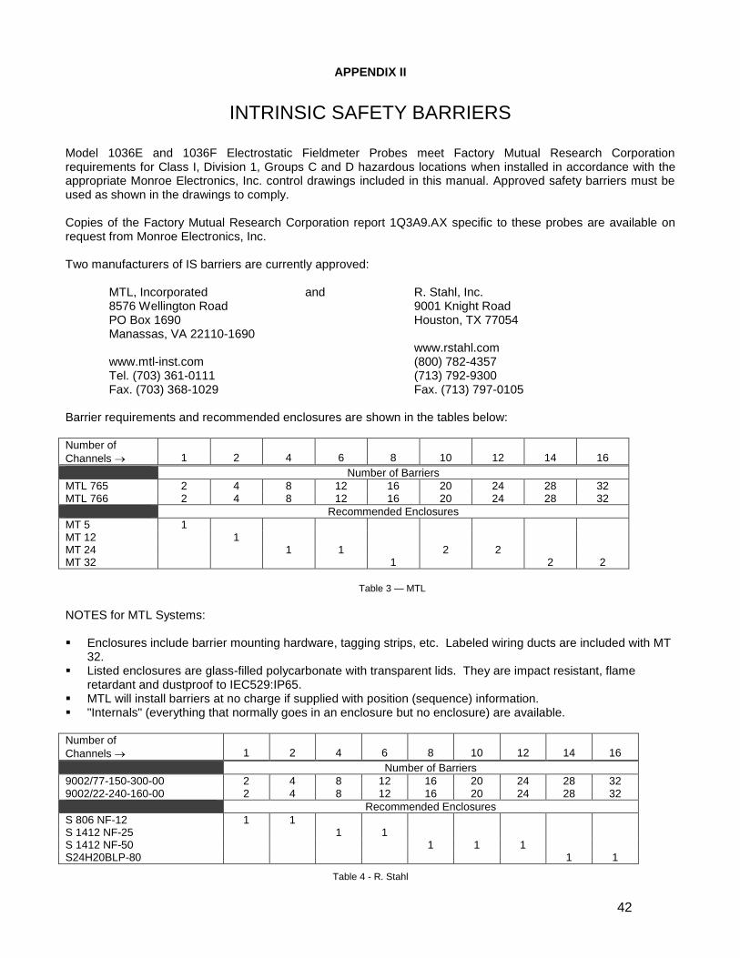
APPENDIX II
INTRINSIC SAFETY BARRIERS
Model 1036E and 1036F Electrostatic Fieldmeter Probes meet Factory Mutual Research Corporation requirements for Class I, Division 1, Groups C and D hazardous locations when installed in accordance with the appropriate Monroe Electronics, Inc. control drawings included in this manual. Approved safety barriers must be used as shown in the drawings to comply. Copies of the Factory Mutual Research Corporation report 1Q3A9.AX specific to these probes are available on request from Monroe Electronics, Inc. Two manufacturers of IS barriers are currently approved: MTL, Incorporated and R. Stahl, Inc. 8576 Wellington Road 9001 Knight Road PO Box 1690 Houston, TX 77054 Manassas, VA 22110-1690 www.rstahl.com www.mtl-inst.com (800) 782-4357 Tel. (703) 361-0111 (713) 792-9300 Fax. (703) 368-1029 Fax. (713) 797-0105 Barrier requirements and recommended enclosures are shown in the tables below: Number of
Channels
1
2
4
6
8
10
12
14
16
Number of Barriers
MTL 765 2 4 8 12 16 20 24 28 32 MTL 766 2 4 8 12 16 20 24 28 32
Recommended Enclosures
MT 5 1 MT 12 1 MT 24 1 1 2 2 MT 32 1 2 2
Table 3 — MTL
NOTES for MTL Systems: Enclosures include barrier mounting hardware, tagging strips, etc. Labeled wiring ducts are included with MT
32. Listed enclosures are glass-filled polycarbonate with transparent lids. They are impact resistant, flame
retardant and dustproof to IEC529:IP65. MTL will install barriers at no charge if supplied with position (sequence) information. "Internals" (everything that normally goes in an enclosure but no enclosure) are available. Number of
Channels
1
2
4
6
8
10
12
14
16
Number of Barriers
9002/77-150-300-00 2 4 8 12 16 20 24 28 32 9002/22-240-160-00 2 4 8 12 16 20 24 28 32
Recommended Enclosures
S 806 NF-12 1 1 S 1412 NF-25 1 1 S 1412 NF-50 1 1 1 S24H20BLP-80 1 1
Table 4 - R. Stahl

43
NOTES for R. Stahl Systems: Enclosures include mounting rails, insulating standoffs, ground terminals and labels. Listed enclosures are Hoffman NEMA-4. Some National Fire Prevention Association (NFPA) publications dealing with the subject of Intrinsic Safety (IS) are:
NFPA 497A - Classification of Class I (Classified) Locations for Electrical Installations in Chemical Process Areas (pamphlet)
NFPA 497M - Classification of Gases, Vapors and Dusts for Electrical Equipment in Hazardous
(Classified) Locations (pamphlet) NFPA 493 - Intrinsically Safe Apparatus for Use in Division 1 Hazardous Locations (pamphlet) NFPA 325M - Fire Hazard Properties of Flammable Liquids, Gases and Volatile Solids (pamphlet) NFPA 496 - Purged and Pressurized Enclosures for Electrical Equipment (pamphlet) Electrical Installations in Hazardous Locations by Peter J. Schram and Mark W. Earley - ISBN 0-87765-
356-9 (book)
The above are available from: National Fire Protection Association 1 Batterymarch Park PO Box 9101 Quincy, MA 02269-9101 Tel. (800) 344-3555
44
APPENDIX III
III.
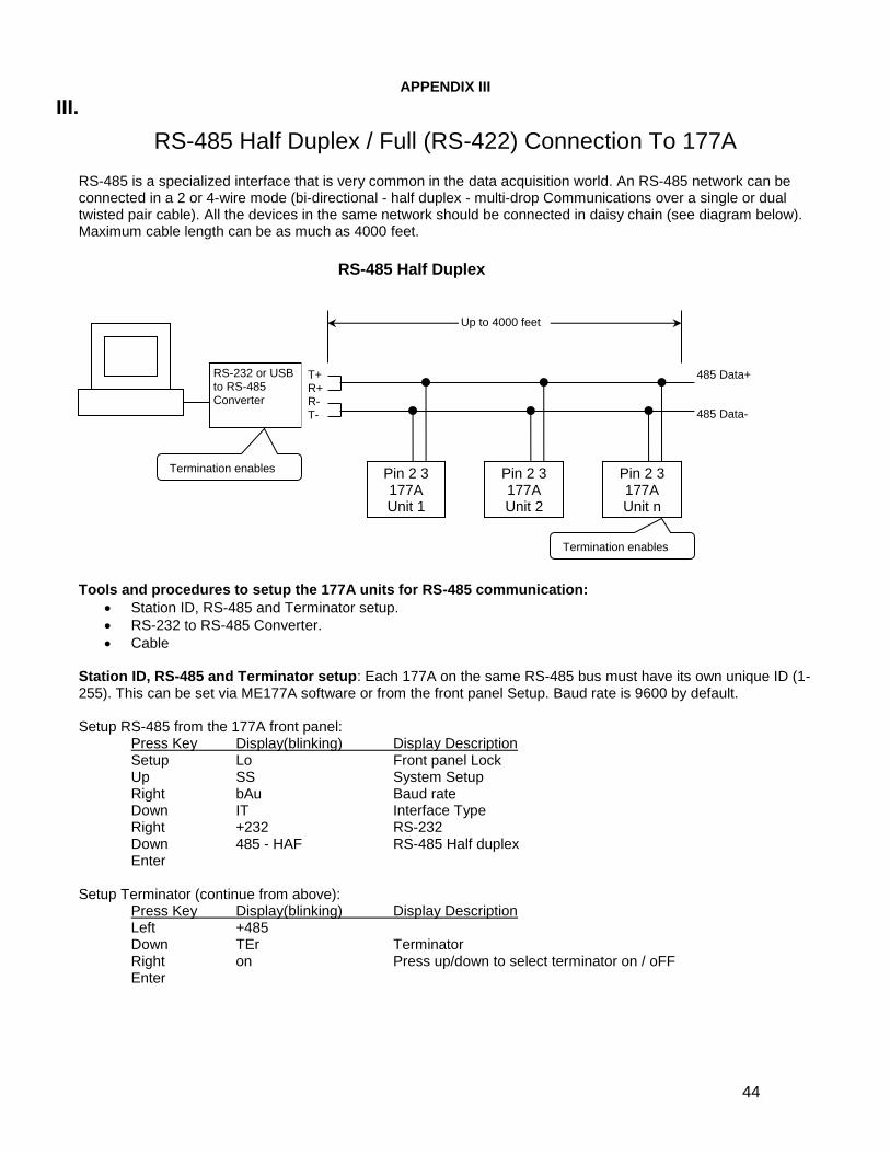
RS-485 Half Duplex / Full (RS-422) Connection To 177A RS-485 is a specialized interface that is very common in the data acquisition world. An RS-485 network can be connected in a 2 or 4-wire mode (bi-directional - half duplex - multi-drop Communications over a single or dual twisted pair cable). All the devices in the same network should be connected in daisy chain (see diagram below). Maximum cable length can be as much as 4000 feet.
Tools and procedures to setup the 177A units for RS-485 communication:
Station ID, RS-485 and Terminator setup.
RS-232 to RS-485 Converter.
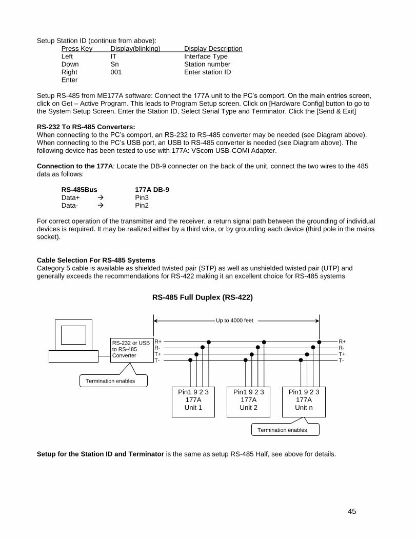
Cable Station ID, RS-485 and Terminator setup: Each 177A on the same RS-485 bus must have its own unique ID (1-255). This can be set via ME177A software or from the front panel Setup. Baud rate is 9600 by default. Setup RS-485 from the 177A front panel: Press Key Display(blinking) Display Description Setup Lo Front panel Lock Up SS System Setup Right bAu Baud rate Down IT Interface Type Right +232 RS-232 Down 485 - HAF RS-485 Half duplex Enter Setup Terminator (continue from above): Press Key Display(blinking) Display Description Left +485 Down TEr Terminator Right on Press up/down to select terminator on / oFF Enter
RS-485 Half Duplex
RS-232 or USB to RS-485 Converter
Pin 2 3 177A Unit 1
Termination enables
Termination enables
Up to 4000 feet
485 Data+
485 Data-
T+ R+ R- T-
Pin 2 3 177A Unit 2
Pin 2 3 177A Unit n
45
Setup Station ID (continue from above): Press Key Display(blinking) Display Description Left IT Interface Type Down Sn Station number Right 001 Enter station ID Enter Setup RS-485 from ME177A software: Connect the 177A unit to the PC’s comport. On the main entries screen, click on Get – Active Program. This leads to Program Setup screen. Click on [Hardware Config] button to go to the System Setup Screen. Enter the Station ID, Select Serial Type and Terminator. Click the [Send & Exit] RS-232 To RS-485 Converters: When connecting to the PC’s comport, an RS-232 to RS-485 converter may be needed (see Diagram above). When connecting to the PC’s USB port, an USB to RS-485 converter is needed (see Diagram above). The following device has been tested to use with 177A: VScom USB-COMi Adapter. Connection to the 177A: Locate the DB-9 connecter on the back of the unit, connect the two wires to the 485 data as follows:
RS-485Bus 177A DB-9 Data+ Pin3 Data- Pin2
For correct operation of the transmitter and the receiver, a return signal path between the grounding of individual devices is required. It may be realized either by a third wire, or by grounding each device (third pole in the mains socket). Cable Selection For RS-485 Systems Category 5 cable is available as shielded twisted pair (STP) as well as unshielded twisted pair (UTP) and generally exceeds the recommendations for RS-422 making it an excellent choice for RS-485 systems
Setup for the Station ID and Terminator is the same as setup RS-485 Half, see above for details.
RS-485 Full Duplex (RS-422)
Termination enables
Termination enables
Up to 4000 feet
Pin1 9 2 3 177A Unit 1
R+ R- T+ T-
R+ R- T+ T-
RS-232 or USB to RS-485 Converter
Pin1 9 2 3 177A Unit 2
Pin1 9 2 3 177A Unit n
46
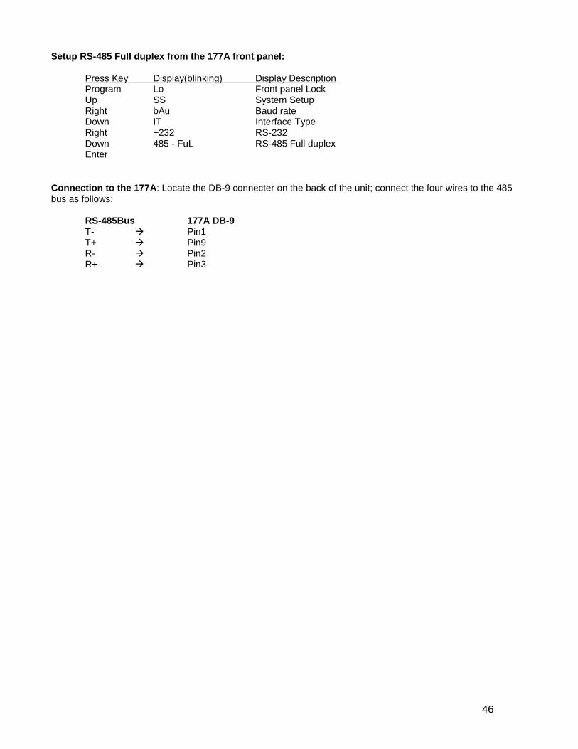
Setup RS-485 Full duplex from the 177A front panel: Press Key Display(blinking) Display Description Program Lo Front panel Lock Up SS System Setup Right bAu Baud rate Down IT Interface Type Right +232 RS-232 Down 485 - FuL RS-485 Full duplex Enter
Connection to the 177A: Locate the DB-9 connecter on the back of the unit; connect the four wires to the 485 bus as follows:
RS-485Bus 177A DB-9 T- Pin1 T+ Pin9 R- Pin2 R+ Pin3
47
APPENDIX IV
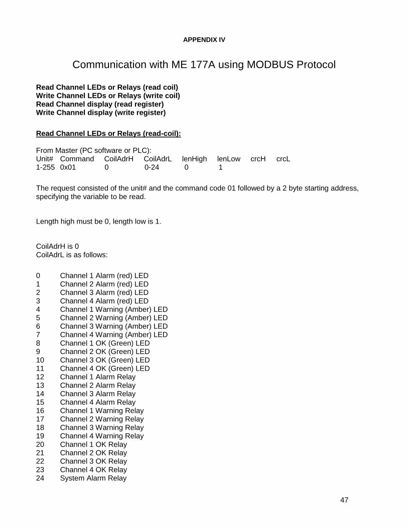
Communication with ME 177A using MODBUS Protocol
Read Channel LEDs or Relays (read coil) Write Channel LEDs or Relays (write coil) Read Channel display (read register) Write Channel display (write register)
Read Channel LEDs or Relays (read-coil): From Master (PC software or PLC): Unit# Command CoilAdrH CoilAdrL lenHigh lenLow crcH crcL 1-255 0x01 0 0-24 0 1
The request consisted of the unit# and the command code 01 followed by a 2 byte starting address, specifying the variable to be read.
Length high must be 0, length low is 1.
CoilAdrH is 0 CoilAdrL is as follows:
0 Channel 1 Alarm (red) LED 1 Channel 2 Alarm (red) LED 2 Channel 3 Alarm (red) LED 3 Channel 4 Alarm (red) LED 4 Channel 1 Warning (Amber) LED 5 Channel 2 Warning (Amber) LED 6 Channel 3 Warning (Amber) LED 7 Channel 4 Warning (Amber) LED 8 Channel 1 OK (Green) LED 9 Channel 2 OK (Green) LED 10 Channel 3 OK (Green) LED 11 Channel 4 OK (Green) LED 12 Channel 1 Alarm Relay 13 Channel 2 Alarm Relay 14 Channel 3 Alarm Relay 15 Channel 4 Alarm Relay 16 Channel 1 Warning Relay 17 Channel 2 Warning Relay 18 Channel 3 Warning Relay 19 Channel 4 Warning Relay 20 Channel 1 OK Relay 21 Channel 2 OK Relay 22 Channel 3 OK Relay 23 Channel 4 OK Relay 24 System Alarm Relay
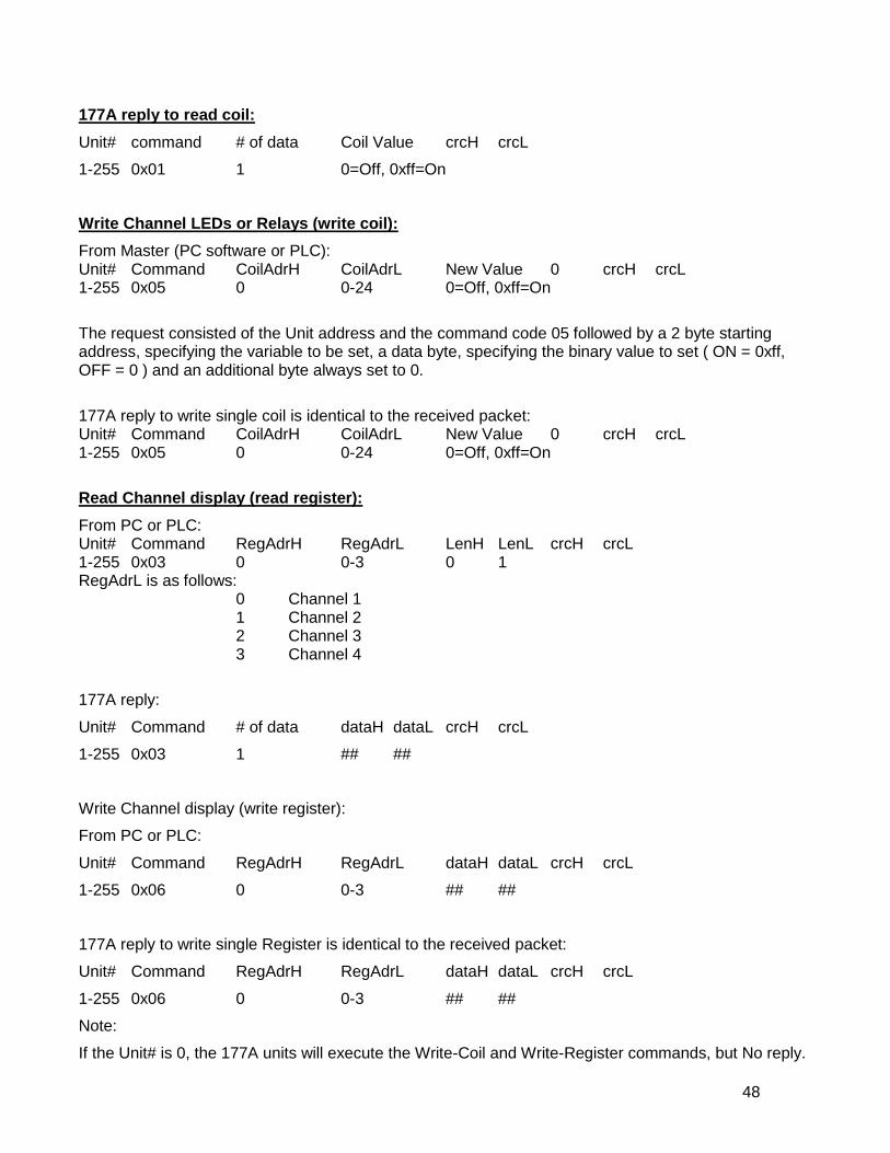
48
177A reply to read coil:
Unit# command # of data Coil Value crcH crcL
1-255 0x01 1 0=Off, 0xff=On
Write Channel LEDs or Relays (write coil):
From Master (PC software or PLC): Unit# Command CoilAdrH CoilAdrL New Value 0 crcH crcL 1-255 0x05 0 0-24 0=Off, 0xff=On
The request consisted of the Unit address and the command code 05 followed by a 2 byte starting address, specifying the variable to be set, a data byte, specifying the binary value to set ( ON = 0xff, OFF = 0 ) and an additional byte always set to 0.
177A reply to write single coil is identical to the received packet: Unit# Command CoilAdrH CoilAdrL New Value 0 crcH crcL 1-255 0x05 0 0-24 0=Off, 0xff=On
Read Channel display (read register):
From PC or PLC: Unit# Command RegAdrH RegAdrL LenH LenL crcH crcL 1-255 0x03 0 0-3 0 1 RegAdrL is as follows:
0 Channel 1 1 Channel 2 2 Channel 3 3 Channel 4
177A reply:
Unit# Command # of data dataH dataL crcH crcL
1-255 0x03 1 ## ##
Write Channel display (write register):
From PC or PLC:
Unit# Command RegAdrH RegAdrL dataH dataL crcH crcL
1-255 0x06 0 0-3 ## ##
177A reply to write single Register is identical to the received packet:
Unit# Command RegAdrH RegAdrL dataH dataL crcH crcL
1-255 0x06 0 0-3 ## ##
Note:
If the Unit# is 0, the 177A units will execute the Write-Coil and Write-Register commands, but No reply.

49
The followings are examples of Read Channel command from PC to 177A, ID=1. The command is 8-byte in length. They are in hex.
Read channel 1:
01 03 00 00 00 01 84 0A
ID Cmd Channel1 crcH crcL
Read channel 2:
01 03 00 01 00 01 D5 CA
ID Cmd Channel2 crcH crcL
Read channel 3:
01 03 00 02 00 01 25 CA
ID Cmd Channel3 crcH crcL
Read channel 4:
01 03 00 03 00 01 74 0A
ID Cmd Channel4 crcH crcL
-------------------------------------------------------
Example1: Reply from the 177A. It is 7-byte in length, shown in hex: 01 03 02 00 33 f8 51
ID Cmd 2-byte data dataHi dataLo crcH crcL
01: Unit ID
03: Read channel command
02: two data bytes followed
00: data high byte
33: data low byte. With the previous high-byte: 00 33 is
the channel reading in hex. Its decimal value is 51.
If the channel is set up for a 10kv probe, the display is 0.51.
f8: crc High byte
51: crc low byte
-------------------------------------------------------
Example2: Reply from the 177A. It is 7-byte in length, shown in hex: 01 03 02 fe 58 f9 de
ID Cmd 2-byte data dataHi dataLo crcH crcL
01: Unit ID
03: Read channel command
02: two data bytes followed
fe: data high byte
58: data low byte. With the previous high-byte: fe 58 is
the channel reading in hex. Its decimal value is -424.
If the channel is set up for a 10kv probe, the display is -4.24.
f9: crc High byte
de: crc low byte
-------------------------------------------------------
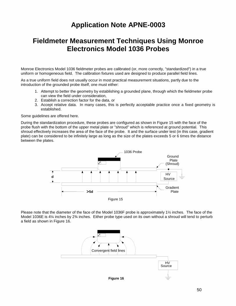
50
Application Note APNE-0003
Fieldmeter Measurement Techniques Using Monroe Electronics Model 1036 Probes
Monroe Electronics Model 1036 fieldmeter probes are calibrated (or, more correctly, "standardized") in a true uniform or homogeneous field. The calibration fixtures used are designed to produce parallel field lines.
As a true uniform field does not usually occur in most practical measurement situations, partly due to the introduction of the grounded probe itself, one must either:
1. Attempt to better the geometry by establishing a grounded plane, through which the fieldmeter probe can view the field under consideration,
2. Establish a correction factor for the data, or 3. Accept relative data. In many cases, this is perfectly acceptable practice once a fixed geometry is
established.
Some guidelines are offered here.
During the standardization procedure, these probes are configured as shown in Figure 15 with the face of the probe flush with the bottom of the upper metal plate or "shroud" which is referenced at ground potential. This shroud effectively increases the area of the face of the probe. It and the surface under test (in this case, gradient plate) can be considered to be infinitely large as long as the size of the plates exceeds 5 or 6 times the distance between the plates.
Please note that the diameter of the face of the Model 1036F probe is approximately 1½ inches. The face of the Model 1036E is 4¼ inches by 2¾ inches. Either probe type used on its own without a shroud will tend to perturb a field as shown in Figure 16.
HV Source
Convergent field lines
Figure 16
1036 Probe
Ground Plate
Gradient Plate
d
>5d
HV
Source
(Shroud)
Figure 15
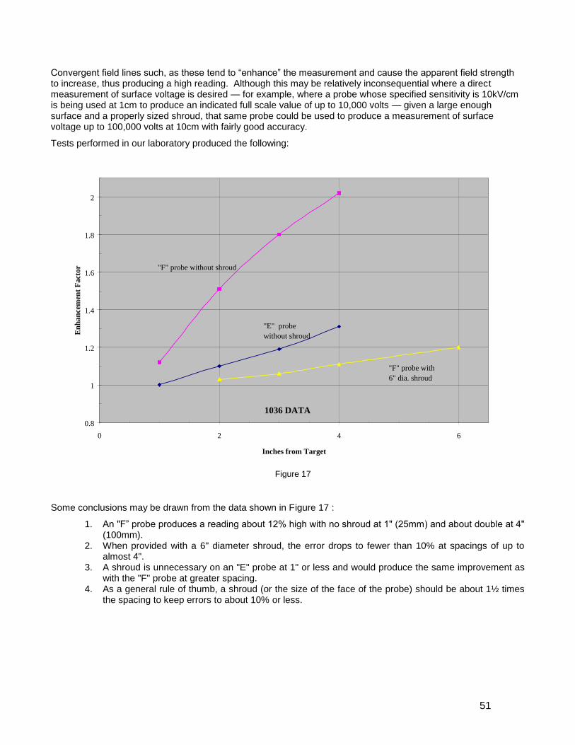
51
Convergent field lines such, as these tend to “enhance” the measurement and cause the apparent field strength to increase, thus producing a high reading. Although this may be relatively inconsequential where a direct measurement of surface voltage is desired — for example, where a probe whose specified sensitivity is 10kV/cm is being used at 1cm to produce an indicated full scale value of up to 10,000 volts — given a large enough surface and a properly sized shroud, that same probe could be used to produce a measurement of surface voltage up to 100,000 volts at 10cm with fairly good accuracy.
Tests performed in our laboratory produced the following:
Some conclusions may be drawn from the data shown in Figure 17 :
1. An "F” probe produces a reading about 12% high with no shroud at 1" (25mm) and about double at 4" (100mm).
2. When provided with a 6" diameter shroud, the error drops to fewer than 10% at spacings of up to almost 4".
3. A shroud is unnecessary on an "E" probe at 1" or less and would produce the same improvement as with the "F" probe at greater spacing.
4. As a general rule of thumb, a shroud (or the size of the face of the probe) should be about 1½ times the spacing to keep errors to about 10% or less.
0.8
1
1.2
1.4
1.6
1.8
2
0 2 4 6
Inches from Target
En
han
cem
ent
Fact
or "F" probe without shroud
"E" probe
without shroud
"F" probe with
6" dia. shroud
1036 DATA
Figure 17
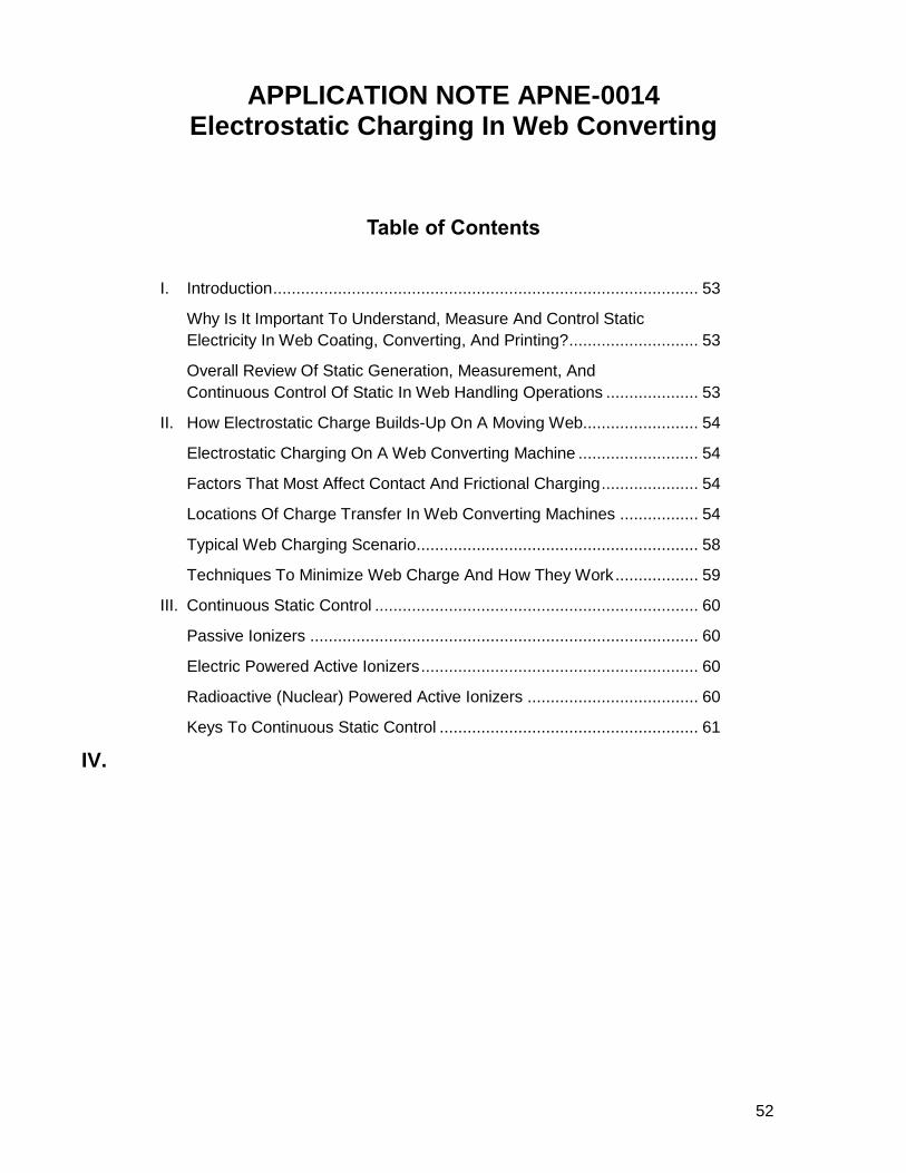
52
APPLICATION NOTE APNE-0014 Electrostatic Charging In Web Converting
Table of Contents
I. Introduction ............................................................................................ 53
Why Is It Important To Understand, Measure And Control Static
Electricity In Web Coating, Converting, And Printing? ............................ 53
Overall Review Of Static Generation, Measurement, And
Continuous Control Of Static In Web Handling Operations .................... 53
II. How Electrostatic Charge Builds-Up On A Moving Web......................... 54
Electrostatic Charging On A Web Converting Machine .......................... 54
Factors That Most Affect Contact And Frictional Charging ..................... 54
Locations Of Charge Transfer In Web Converting Machines ................. 54
Typical Web Charging Scenario ............................................................. 58
Techniques To Minimize Web Charge And How They Work .................. 59
III. Continuous Static Control ...................................................................... 60
Passive Ionizers .................................................................................... 60
Electric Powered Active Ionizers ............................................................ 60
Radioactive (Nuclear) Powered Active Ionizers ..................................... 60
Keys To Continuous Static Control ........................................................ 61
IV.

APNE-0015 53
I. Introduction
Why Is It Important To Understand, Measure And Control Static Electricity In Web Coating, Converting, And Printing?
Statically charged materials on the converting machine, the web, or both may attract or repel the web to itself or to the machine. This material misbehavior can adversely affect the manufacturing process by causing jams and downtime, reduced productivity, and/or poor product quality.
Static on the web can attract contamination such as dust and other particulates, resulting in coating or printing defects.
Static shocks received by operators can cause dangerous physical reactions by the persons receiving the shocks, possibly resulting in injuries or death from moving machinery.
Static sparks in hazardous operations such as solvent-based coating or printing can cause fires and explosions, possibly resulting in injuries or death to people, destruction of the equipment or facility, and lost production.
Overall Review Of Static Generation, Measurement, And Continuous Control Of Static In Web Handling Operations
This document provides the reader with a review of web static charging mechanisms, web and machine factors most involved in static charging, typical locations of web static charging, and techniques to minimize web charging.
Generation and control of static in web converting depends upon many varying conditions in the web material, the converting machine, the surrounding atmosphere, and the static control measures used on the machine. It is impossible to predict and control all of these conditions because they can change without one realizing it until a statically caused event occurs. Changing conditions can alter the amount of static charge accumulation, so although static is under control today, it may not be under control tomorrow.
The keys to continuous static control are (1) the correct determination of critical areas of the machine to monitor for static charge accumulation, (2) application of static countermeasures and devices that prevent or control static charge accumulation, and (3) continuous electric field measurement in these critical areas using permanent fieldmeters, which are alarmed to warn or shutdown the operation when web static charge levels increase beyond predetermined set points.
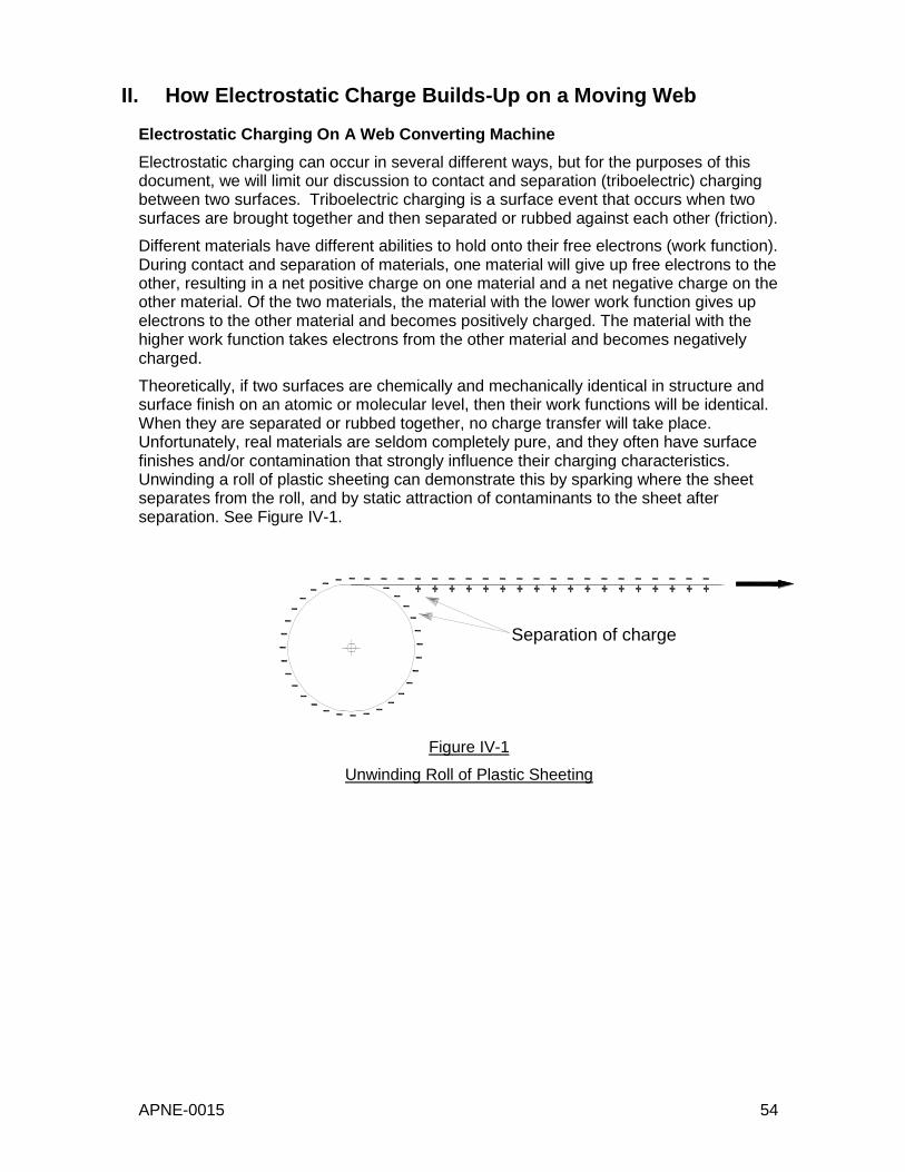
APNE-0015 54
II. How Electrostatic Charge Builds-Up on a Moving Web
Electrostatic Charging On A Web Converting Machine
Electrostatic charging can occur in several different ways, but for the purposes of this document, we will limit our discussion to contact and separation (triboelectric) charging between two surfaces. Triboelectric charging is a surface event that occurs when two surfaces are brought together and then separated or rubbed against each other (friction).
Different materials have different abilities to hold onto their free electrons (work function). During contact and separation of materials, one material will give up free electrons to the other, resulting in a net positive charge on one material and a net negative charge on the other material. Of the two materials, the material with the lower work function gives up electrons to the other material and becomes positively charged. The material with the higher work function takes electrons from the other material and becomes negatively charged.
Theoretically, if two surfaces are chemically and mechanically identical in structure and surface finish on an atomic or molecular level, then their work functions will be identical. When they are separated or rubbed together, no charge transfer will take place. Unfortunately, real materials are seldom completely pure, and they often have surface finishes and/or contamination that strongly influence their charging characteristics. Unwinding a roll of plastic sheeting can demonstrate this by sparking where the sheet separates from the roll, and by static attraction of contaminants to the sheet after separation. See Figure IV-1.
Figure IV-1
Unwinding Roll of Plastic Sheeting
Separation of charge
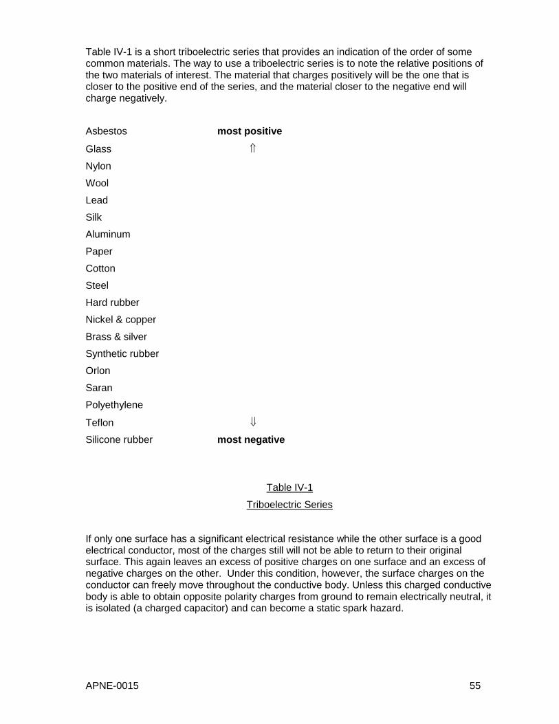
APNE-0015 55
Table IV-1 is a short triboelectric series that provides an indication of the order of some common materials. The way to use a triboelectric series is to note the relative positions of the two materials of interest. The material that charges positively will be the one that is closer to the positive end of the series, and the material closer to the negative end will charge negatively.
Asbestos most positive
Glass
Nylon
Wool
Lead
Silk
Aluminum
Paper
Cotton
Steel
Hard rubber
Nickel & copper
Brass & silver
Synthetic rubber
Orlon
Saran
Polyethylene
Teflon
Silicone rubber most negative
Table IV-1
Triboelectric Series
If only one surface has a significant electrical resistance while the other surface is a good electrical conductor, most of the charges still will not be able to return to their original surface. This again leaves an excess of positive charges on one surface and an excess of negative charges on the other. Under this condition, however, the surface charges on the conductor can freely move throughout the conductive body. Unless this charged conductive body is able to obtain opposite polarity charges from ground to remain electrically neutral, it is isolated (a charged capacitor) and can become a static spark hazard.

APNE-0015 56
Factors That Most Affect Triboelectric Charging
Contact Pressure: Increased pressure increases contact area by reducing the air gap between surfaces.
Contact Time: Increased contact time can increase charge transfer by enlarging the contact area.
Draining Velocity: The speed at which charges travel along the web toward recombination. It is relatively constant and independent of parting velocity, but is directly related to web front/back surface and bulk conductivity. Net charge builds on a web when parting velocity is greater than draining velocity.
Electric Field: The electric field generated at the location where the surfaces separate may provide enough force to affect the return of charges to their original surfaces.
Humidity: As humidity is increased, generally material conductivity increases, and charge accumulation decreases due to charge backflow.
Particulate Contamination: Dust and other particulates on surface layers affect surface chemistry and contact area, which affect charging.
Parting Velocity or Separation Speed: Affects the time electrons have available for returning to their original surface. Generally, the faster the surfaces are separated the more charge is left on the surfaces.
Slip (or Slide): Causes frictional charging due to relative motion between surfaces. This can also cause transfer of actual material from one surface to the other, which will affect charging as well.
Surface Hardness: Soft surfaces make contact that is more intimate and tend to cause more charging during separation.
Surface Layer Chemistry: Affects how charging takes place when surfaces of differing work functions contact each other.
Surface Roughness: Charge transfer decreases as surface roughness increases due to less contact area between the surfaces.
Temperature: Elevated surface temperatures usually result in increased charge transfer due to higher molecular energy levels as well as to decreased surface moisture films.
Locations Of Charge Transfer In Web Converting Machines
When the web is wound into roll form, the face and back are in contact. So charge transfer can occur during unwinding (see Figure IV-1 for example). Surface chemistry and intimacy of contact are important factors here. Sometimes "charge balancing" is attempted by chemists who add surfactants and other chemicals to the surfaces to control front-to-back charging. In addition, the more intimate (greater) the contact between layers, the more charge is transferred. Intimacy is influenced by such factors as surface hardness, roughness, thickness, force concentration, and winding tension. Roll history (moisture changes, temperature changes, winding tension) can be an important factor because it may affect conductivity or contact area.
Corona discharge treatment (CDT) is applied to the web in some converting processes. CDT treatment is used to increase the web’s ability to accept coating or printing layers. Because CDT purposely generates large quantities of ions to alter the web’s physical characteristics, high charges are also left on the web, which then must be reduced or eliminated.
APNE-0015 57
Webs and rollers exchange charge because of differences in material properties. The factors that we saw above translate into the following factors in a coating, converting, or printing machine:
Roller bulk conductivity and surface conductivity
Roller surface chemistry (material and contamination)
Roller surface roughness, texture, and venting
Roller/Web alignment and tracking
Roller/Web frictional drag (bearing failure)
Roller/Web intimacy of contact (surface hardness or compliance)
Roller/Web wrap angle
Web bulk conductivity and front/back surface conductivity
Web slip and weave
Web speed and tension
Web surface chemistry (material, antistatic agents, surfactants and contamination)
Web surface roughness and texture
Any other object that the web touches, such as turning bars, splice board, and the operator's hand, can also cause charge transfer.
High electric fields that occur at the separation of surfaces, such as at the nip of unwinding rolls or roller/web contacts, can result in corona discharges (glow). Corona discharges produce ions of both polarities that tend to reduce the overall web charge. Static control devices (passive or active ionizers) ionize air in order to control charges on the web by attracting opposite polarity air ions to neutralize the charges on the web.
Strong electric fields on insulating surfaces in the converting machine can charge ungrounded conductors (including people) by induction, especially at wind-up and delivery areas. These charged conductors could then release dangerous sparks to any other nearby conductor.
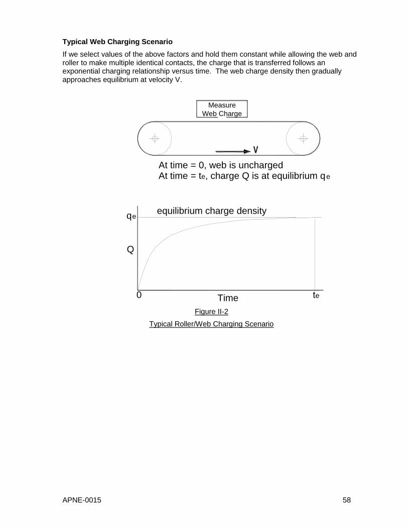
APNE-0015 58
Typical Web Charging Scenario
If we select values of the above factors and hold them constant while allowing the web and roller to make multiple identical contacts, the charge that is transferred follows an exponential charging relationship versus time. The web charge density then gradually approaches equilibrium at velocity V.
Figure II-2
Typical Roller/Web Charging Scenario
Measure
Web Charge
At time = 0, web is unchargedAt time = te, charge Q is at equilibrium qe
equilibrium charge density
Time te
qe
Q
0

APNE-0015 59
Techniques To Minimize Web Charge And How They Work
As much as possible, control the factors that govern charge transfer from objects (e.g. rollers, web laps) to the web. Usually, not all factors are known and/or controllable. Some general guidelines for reducing web charge transfer can be given, but they may be product and process dependent.
Electrically ground all conductive machine parts including rollers (use conductive bearings and conductive bearing lubricants) to eliminate dangerous sparking from capacitive discharges to another conductor such as a person or metal. Please note that grounded conductive rollers cannot reduce charges of insulating web surfaces that pass over them! The purpose of grounding the rollers is to prevent the rollers from becoming highly charged.
Maintain web-converting machines in excellent condition, making sure rollers are in alignment and turning freely.
Use web substrates and coating materials that are conductive or dissipative, or can be made so before converting begins with the addition of antistatic agents.
Use web substrates that were manufactured, wound, and packaged in environments with 50% or higher relative humidity (RH).
Control RH in the web converting machine environment to 50-55%. Higher levels can cause iron and steel parts to rust, and may be uncomfortable to operators working in the area. In building areas with uncontrolled humidity, increased static charging is usually very dramatic during the winter when RH in heated buildings can frequently drop to less than 10%.
If possible, avoid using pinch drive rollers. If they must be used, minimize the pinch roller pressure and tackiness.
Reduce machine speed and web tension as much as practical.
Increase web and roller surface roughness as much as practical.
Clean machine rollers frequently. Web/roller electrification can be affected by previous products because of web material transfer to the rollers.
Control drying conditions of web coatings to as low a temperature, and as high a relative humidity, as practical.
Cover conductive rollers only with sleeves made of conductive or dissipative material. Large amounts of charge can be stored at the interface of resistive sleeve material and a conductor, which can be released in very hazardous sparks either spontaneously or when approached by a person (conductor).
Use passive and/or active ionization devices to reduce web charge density. If properly installed in the correct locations, it may be possible to initially control all static problems on the web-converting machine using ionization. Over time, though, the effectiveness of all these devices will degrade, and they will have to be cleaned, maintained, or replaced to return their effectiveness to original condition. The proper operation and effectiveness of ionization systems can be verified by continuous downstream monitoring using permanent installations of Monroe Electronics Model 177A fieldmeters with Monroe 1036 fieldmeter probes.
The application note, ANPE-0015 Electric Fields and Fieldmeters, deals with the practical issues of measuring and interpreting electric fields with the Monroe Electronics Models 265A and 282 handheld fieldmeters to determine where continuous monitoring is necessary.
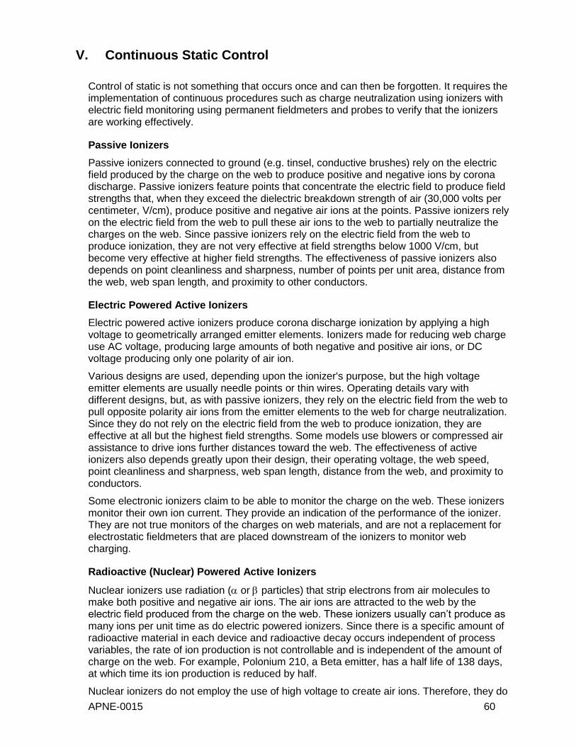
APNE-0015 60
V. Continuous Static Control
Control of static is not something that occurs once and can then be forgotten. It requires the implementation of continuous procedures such as charge neutralization using ionizers with electric field monitoring using permanent fieldmeters and probes to verify that the ionizers are working effectively.
Passive Ionizers
Passive ionizers connected to ground (e.g. tinsel, conductive brushes) rely on the electric field produced by the charge on the web to produce positive and negative ions by corona discharge. Passive ionizers feature points that concentrate the electric field to produce field strengths that, when they exceed the dielectric breakdown strength of air (30,000 volts per centimeter, V/cm), produce positive and negative air ions at the points. Passive ionizers rely on the electric field from the web to pull these air ions to the web to partially neutralize the charges on the web. Since passive ionizers rely on the electric field from the web to produce ionization, they are not very effective at field strengths below 1000 V/cm, but become very effective at higher field strengths. The effectiveness of passive ionizers also depends on point cleanliness and sharpness, number of points per unit area, distance from the web, web span length, and proximity to other conductors.
Electric Powered Active Ionizers
Electric powered active ionizers produce corona discharge ionization by applying a high voltage to geometrically arranged emitter elements. Ionizers made for reducing web charge use AC voltage, producing large amounts of both negative and positive air ions, or DC voltage producing only one polarity of air ion.
Various designs are used, depending upon the ionizer's purpose, but the high voltage emitter elements are usually needle points or thin wires. Operating details vary with different designs, but, as with passive ionizers, they rely on the electric field from the web to pull opposite polarity air ions from the emitter elements to the web for charge neutralization. Since they do not rely on the electric field from the web to produce ionization, they are effective at all but the highest field strengths. Some models use blowers or compressed air assistance to drive ions further distances toward the web. The effectiveness of active ionizers also depends greatly upon their design, their operating voltage, the web speed, point cleanliness and sharpness, web span length, distance from the web, and proximity to conductors.
Some electronic ionizers claim to be able to monitor the charge on the web. These ionizers monitor their own ion current. They provide an indication of the performance of the ionizer. They are not true monitors of the charges on web materials, and are not a replacement for electrostatic fieldmeters that are placed downstream of the ionizers to monitor web charging.
Radioactive (Nuclear) Powered Active Ionizers
Nuclear ionizers use radiation ( or particles) that strip electrons from air molecules to make both positive and negative air ions. The air ions are attracted to the web by the electric field produced from the charge on the web. These ionizers usually can’t produce as many ions per unit time as do electric powered ionizers. Since there is a specific amount of radioactive material in each device and radioactive decay occurs independent of process variables, the rate of ion production is not controllable and is independent of the amount of charge on the web. For example, Polonium 210, a Beta emitter, has a half life of 138 days, at which time its ion production is reduced by half.
Nuclear ionizers do not employ the use of high voltage to create air ions. Therefore, they do
APNE-0015 61
not create a threat of explosion or fire when used with solvents-based coating or printing applications.
Nuclear ionizers are a controlled device subject to licensing and regulation.
Key To Continuous Static Control
The keys to continuous static control are: (1) Correct determination of critical machine areas to (2) monitor continuously. Then (3) implement static control devices and continuous electric field measurement in these critical areas using permanent fieldmeters which are (4) alarmed to warn or shutdown the operation when web static charge levels increase beyond predetermined set points.
APNE-0015 62
APPLICATION NOTE APNE-0015
Electric Fields and Fieldmeters in Web Converting
VI.
Table of Contents
I. Introduction .................................................................................................. 63
Content ........................................................................................................ 63
Review ......................................................................................................... 63
II. Electric Fields and Fieldmeters .................................................................... 63
Electric Field ................................................................................................ 63
Electric Fieldmeters ..................................................................................... 64
Effect of Probe Type on Fieldmeter Readings .............................................. 66
Investigation of High Electric Field Problem Areas w/ Handheld Fieldmeters68
Effect of Operator Presence on Fieldmeter Readings .................................. 69
Taking Handheld Fieldmeter Measurements ................................................ 69
Calculating web surface charge density ....................................................... 74
Relating web surface charge density to the real world ................................. 74
Continuous monitoring of electric fields in high-
risk machine/product performance areas ............................................... 74
III. References .................................................................................................. 75
APNE-0016 63
VII. I. Introduction
Content
This document provides the reader with a review of how fieldmeters operate to measure electric fields, the effects of web-converting machine geometry and operator techniques when measuring electric fields, how handheld fieldmeters are used to investigate where static problem areas exist on machines, and techniques for interpreting fieldmeter readings.
This document is the second in a series of three application notes about static charging of materials and equipment in web converting machines, including recommendations for static measurement, control, and continuous monitoring. The first document in this series is application note APNE-0014 Electrostatic Charging In Web Converting.
Review
Generation and control of static in web converting depends upon many varying conditions in the web material, the converting machine, the surrounding atmosphere, and the static control measures used on the machine. It is impossible to predict and control all of these conditions because they can change without one realizing it until a statically caused event occurs. Changing conditions can alter the amount of static charge accumulation, so although static is under control today, it may not be under control tomorrow.
The keys to continuous static control are
1. The correct determination of critical areas of the machine to monitor for static charge accumulation,
2. Application of static countermeasures and devices that prevent or control static charge accumulation, and
3. Continuous electric field measurement in these critical areas using permanent fieldmeters, which are alarmed to warn or shutdown the operation when web static charge levels increase beyond predetermined set points.
VIII. II. Electric Fields and Fieldmeters
Electric Field
An electric field is a region of space characterized by the existence of an electric force (F) generated by an electric charge (q). The electric force F acting on a charge q in an electric field is proportional to the charge itself. The relationship of these quantities is expressed by the electrostatic force law [1]:
F = qE
E is called the electric field strength and is determined by the magnitude and locations of the other charges acting upon charge q:
E = F/q
The electric field strength, E, is usually displayed in the unit of volt/meter (V/m), volt/centimeter (V/cm) or volt/inch (V/in).
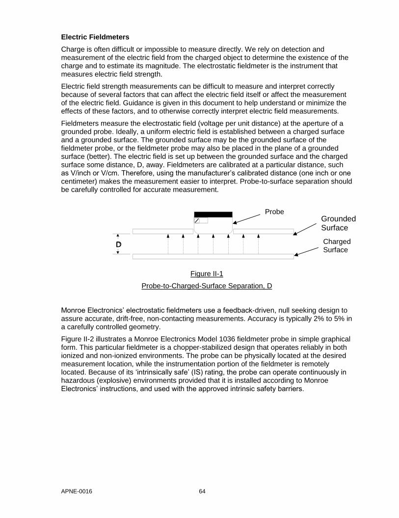
APNE-0016 64
Electric Fieldmeters
Charge is often difficult or impossible to measure directly. We rely on detection and measurement of the electric field from the charged object to determine the existence of the charge and to estimate its magnitude. The electrostatic fieldmeter is the instrument that measures electric field strength.
Electric field strength measurements can be difficult to measure and interpret correctly because of several factors that can affect the electric field itself or affect the measurement of the electric field. Guidance is given in this document to help understand or minimize the effects of these factors, and to otherwise correctly interpret electric field measurements.
Fieldmeters measure the electrostatic field (voltage per unit distance) at the aperture of a grounded probe. Ideally, a uniform electric field is established between a charged surface and a grounded surface. The grounded surface may be the grounded surface of the fieldmeter probe, or the fieldmeter probe may also be placed in the plane of a grounded surface (better). The electric field is set up between the grounded surface and the charged surface some distance, D, away. Fieldmeters are calibrated at a particular distance, such as V/inch or V/cm. Therefore, using the manufacturer’s calibrated distance (one inch or one centimeter) makes the measurement easier to interpret. Probe-to-surface separation should be carefully controlled for accurate measurement.
Figure II-1
Probe-to-Charged-Surface Separation, D
Monroe Electronics’ electrostatic fieldmeters use a feedback-driven, null seeking design to assure accurate, drift-free, non-contacting measurements. Accuracy is typically 2% to 5% in a carefully controlled geometry.
Figure II-2 illustrates a Monroe Electronics Model 1036 fieldmeter probe in simple graphical form. This particular fieldmeter is a chopper-stabilized design that operates reliably in both ionized and non-ionized environments. The probe can be physically located at the desired measurement location, while the instrumentation portion of the fieldmeter is remotely located. Because of its ‘intrinsically safe’ (IS) rating, the probe can operate continuously in hazardous (explosive) environments provided that it is installed according to Monroe Electronics’ instructions, and used with the approved intrinsic safety barriers.
D
Grounded Surface
D
Probe
Charged Surface

APNE-0016 65
Figure II-2
Monroe Model 1036 Fieldmeter Probe
Electrostatic fieldmeters measure electric field strength by non-contacting means. All the charged objects, voltage sources, and grounded conductors (including the fieldmeter probe housing) in the general area affect the electric field strength measurement. The fieldmeter measures the electric field strength only at its aperture. It does not have a viewing angle and it does not see the web or object directly in front of it as a separate entity. This can be demonstrated by measuring the electric field of an insulating sheet with a hole in it.
Figure II-3
Insulating Sheet Electric Field Demo, Top View
The field over the hole will not be zero even though there is no charge directly in front of the probe head. This is because the electric field at the probe aperture is a function of each charge on the sheet, and is also a function of the concentration of field due to the grounded probe itself.
Place a charge on an insulating sheet with a hole cut out of it
(hole to be larger than probe) .
Measure the electric field over
the sheet (a). Move the probe over the hole and measure the
field again (b).
The measured field strength in
(b) will be less than in (a), but it
won’t be zero.
Probe
Probe Hole
Hole
(a) (b)
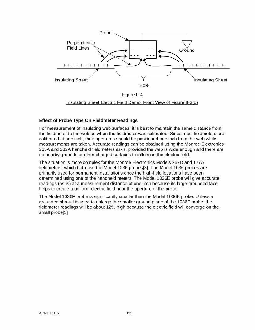
APNE-0016 66
Figure II-4
Insulating Sheet Electric Field Demo, Front View of Figure II-3(b)
Effect of Probe Type On Fieldmeter Readings
For measurement of insulating web surfaces, it is best to maintain the same distance from the fieldmeter to the web as when the fieldmeter was calibrated. Since most fieldmeters are calibrated at one inch, their apertures should be positioned one inch from the web while measurements are taken. Accurate readings can be obtained using the Monroe Electronics 265A and 282A handheld fieldmeters as-is, provided the web is wide enough and there are no nearby grounds or other charged surfaces to influence the electric field.
The situation is more complex for the Monroe Electronics Models 257D and 177A fieldmeters, which both use the Model 1036 probes[3]. The Model 1036 probes are primarily used for permanent installations once the high-field locations have been determined using one of the handheld meters. The Model 1036E probe will give accurate readings (as-is) at a measurement distance of one inch because its large grounded face helps to create a uniform electric field near the aperture of the probe.
The Model 1036F probe is significantly smaller than the Model 1036E probe. Unless a grounded shroud is used to enlarge the smaller ground plane of the 1036F probe, the fieldmeter readings will be about 12% high because the electric field will converge on the small probe[3]
Insulating Sheet
+ + + + + + + + + + + + + + + + + + + + + +
Ground
- - - - -
- - - - -
Perpendicular Field Lines
Probe
Insulating Sheet Hole
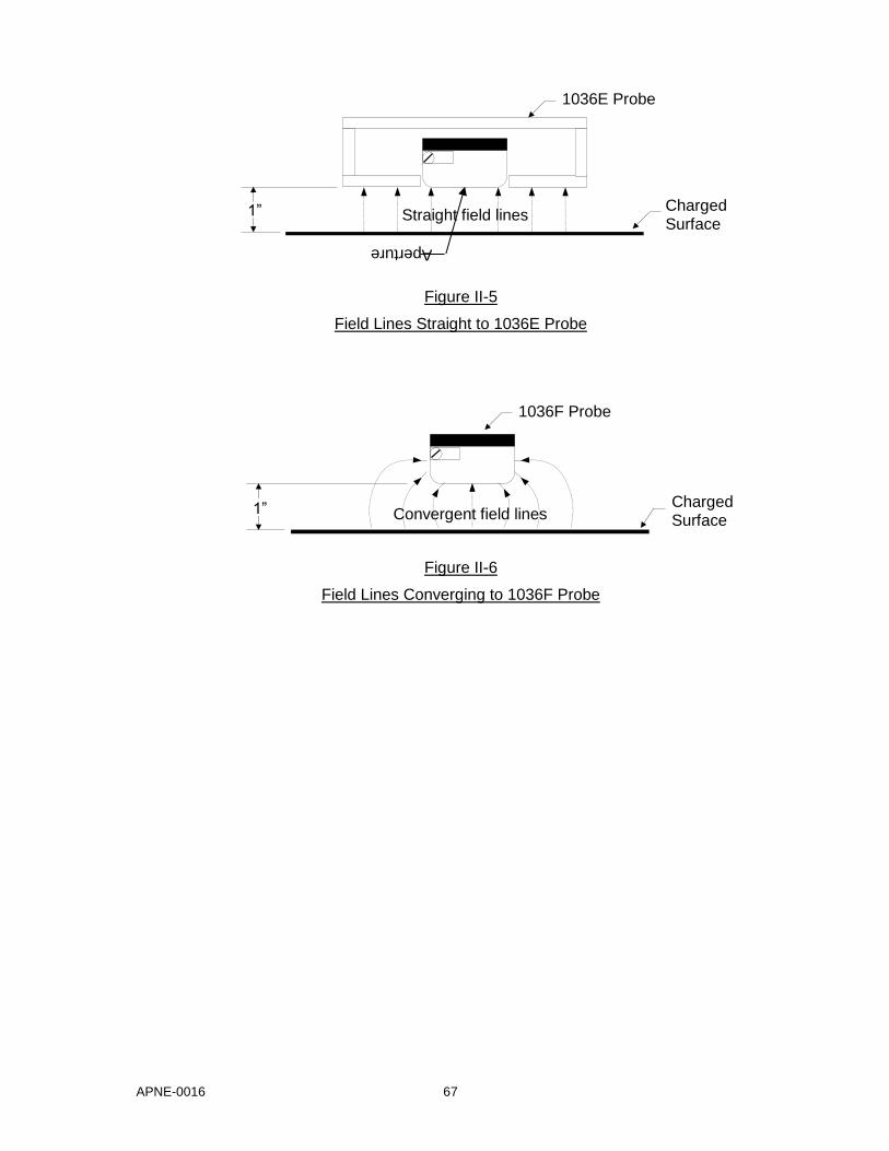
APNE-0016 67
Figure II-5
Field Lines Straight to 1036E Probe
Figure II-6
Field Lines Converging to 1036F Probe
Convergent field lines
1036F Probe
Charged Surface
1”
Straight field lines
1036E Probe
Charged Surface
1”
Aperture
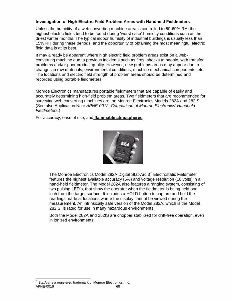
APNE-0016 68
Investigation of High Electric Field Problem Areas with Handheld Fieldmeters
Unless the humidity of a web converting machine area is controlled to 50-60% RH, the highest electric fields tend to be found during ‘worst case’ humidity conditions such as the driest winter months. The typical indoor humidity of industrial buildings is usually less than 15% RH during these periods, and the opportunity of obtaining the most meaningful electric field data is at its best.
It may already be apparent where high electric field problem areas exist on a web-converting machine due to previous incidents such as fires, shocks to people, web transfer problems and/or poor product quality. However, new problems areas may appear due to changes in raw materials, environmental conditions, machine mechanical components, etc. The locations and electric field strength of problem areas should be determined and recorded using portable fieldmeters.
Monroe Electronics manufactures portable fieldmeters that are capable of easily and accurately determining high-field problem areas. Two fieldmeters that are recommended for surveying web converting machines are the Monroe Electronics Models 282A and 282IS. (See also Application Note APNE-0012, Comparison of Monroe Electronics' Handheld Fieldmeters.)
For accuracy, ease of use, and flammable atmospheres
The Monroe Electronics Model 282A Digital Stat-Arc 3 Electrostatic Fieldmeter features the highest available accuracy (5%) and voltage resolution (10 volts) in a hand-held fieldmeter. The Model 282A also features a ranging system, consisting of two pulsing LED’s, that show the operator when the fieldmeter is being held one inch from the target surface. It includes a HOLD button to capture and hold the readings made at locations where the display cannot be viewed during the measurement. An intrinsically safe version of the Model 282A, which is the Model 282IS, is rated for use in many hazardous environments.
Both the Model 282A and 282IS are chopper stabilized for drift-free operation, even in ionized environments.
StatArc is a registered trademark of Monroe Electronics, Inc.
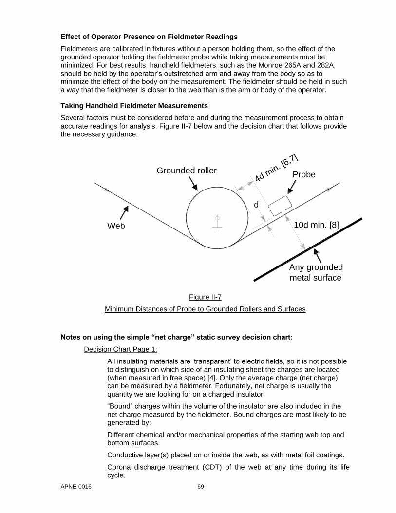
APNE-0016 69
Effect of Operator Presence on Fieldmeter Readings
Fieldmeters are calibrated in fixtures without a person holding them, so the effect of the grounded operator holding the fieldmeter probe while taking measurements must be minimized. For best results, handheld fieldmeters, such as the Monroe 265A and 282A, should be held by the operator’s outstretched arm and away from the body so as to minimize the effect of the body on the measurement. The fieldmeter should be held in such a way that the fieldmeter is closer to the web than is the arm or body of the operator.
Taking Handheld Fieldmeter Measurements
Several factors must be considered before and during the measurement process to obtain accurate readings for analysis. Figure II-7 below and the decision chart that follows provide the necessary guidance.
Figure II-7
Minimum Distances of Probe to Grounded Rollers and Surfaces
Notes on using the simple “net charge” static survey decision chart:
Decision Chart Page 1:
All insulating materials are ‘transparent’ to electric fields, so it is not possible to distinguish on which side of an insulating sheet the charges are located (when measured in free space) [4]. Only the average charge (net charge) can be measured by a fieldmeter. Fortunately, net charge is usually the quantity we are looking for on a charged insulator.
“Bound” charges within the volume of the insulator are also included in the net charge measured by the fieldmeter. Bound charges are most likely to be generated by:
Different chemical and/or mechanical properties of the starting web top and bottom surfaces.
Conductive layer(s) placed on or inside the web, as with metal foil coatings.
Corona discharge treatment (CDT) of the web at any time during its life cycle.
d
4d min. [6
,7]
Grounded roller
10d min. [8]
Any grounded
metal surface
Probe
Web

APNE-0016 70
Pinch roller operation, as when the web runs over a metal gravure cylinder with a rubber impression roller applying pressure to the cylinder.
One must be careful that a high ‘bound’ charge is not captured within the insulator, lest a condition for highly energetic propagating brush discharges be established [4,9].
Bound charge investigation requires the use of a properly shielded electrostatic voltmeter (see www.monroe-electronics.com/esd_pages/voltmeters.htm) in addition to a fieldmeter, and is best left to an expert.
Decision Chart Page 2:
Typical locations for verifying low web fields are at hazardous operations such as rotogravure solvent printing. Measure electric fields after the last grounded roller (or after any ionizer), but before the gravure printing roller, and then after the gravure roller (or after any ionizer), but before the next grounded roller.
High fields that are causing electrostatic discharges (ESD) in a moving web-converting machine can be quickly located by moving along the machine holding a portable AM radio tuned off-station in an unused frequency band. The static heard over the speaker or headphones will increase near the ESD locations, and may produce a discrete popping noise. The radio picks up the static discharges because they generate broadband electromagnetic radiation.
Decision Chart Page 3:
For fields beginning to exceed ±20kV/in on the Model 282A fieldmeter, move the Model 282A to four inches from the web and observe the reading. Multiply the reading by a factor of two to obtain the actual field strength, up to ±40kV/in. If the reading on the 282A begins to exceed ±20kV/in at four inches, back off to 6.5 inches and multiply the reading by 3 to obtain the result, up to ±60kV/in. If the reading on the 282A begins to exceed ±60kV/in at 6.5 inches, back off to 8.5 inches and multiply the reading by 4 to obtain the result, up to ±80kV/in.Keep in mind that the available web target size specified in Note 5 needs to increase by a factor of 4 times d.
For both the 282A and 282IS fieldmeters, the minimum distances shown in Figure II-7 must increase by the indicated factor times the measurement distance, d (Note 1 & Note 2). These minimum distances must be maintained to prevent conductive, grounded surfaces from suppressing the electric field.
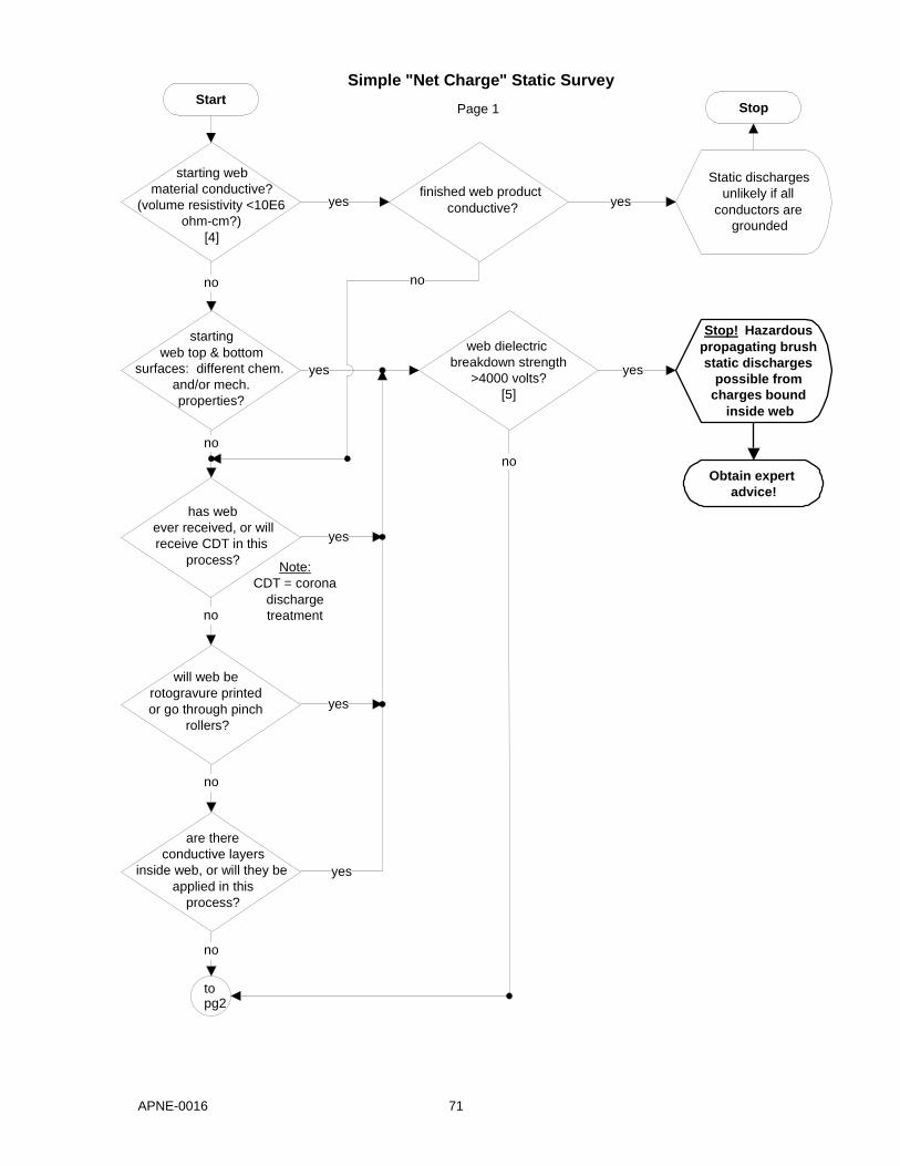
APNE-0016 71
are there conductive layers
inside web, or will they be applied in this
process?
starting web material conductive?
(volume resistivity <10E6 ohm-cm?)
[4]
Start
starting web top & bottom
surfaces: different chem. and/or mech. properties?
Simple "Net Charge" Static Survey
has web ever received, or will receive CDT in this
process?
will web be rotogravure printed or go through pinch
rollers?
to pg2
no
no
finished web product conductive?
Stop
yes
no
no
no
web dielectric breakdown strength
>4000 volts? [5]
yes
yes
yes
yes
Stop! Hazardous propagating brush static discharges
possible from charges bound
inside web
Obtain expert advice!
yes
no
no
Static discharges unlikely if all
conductors are grounded
yes
Note: CDT = corona
discharge treatment
Page 1
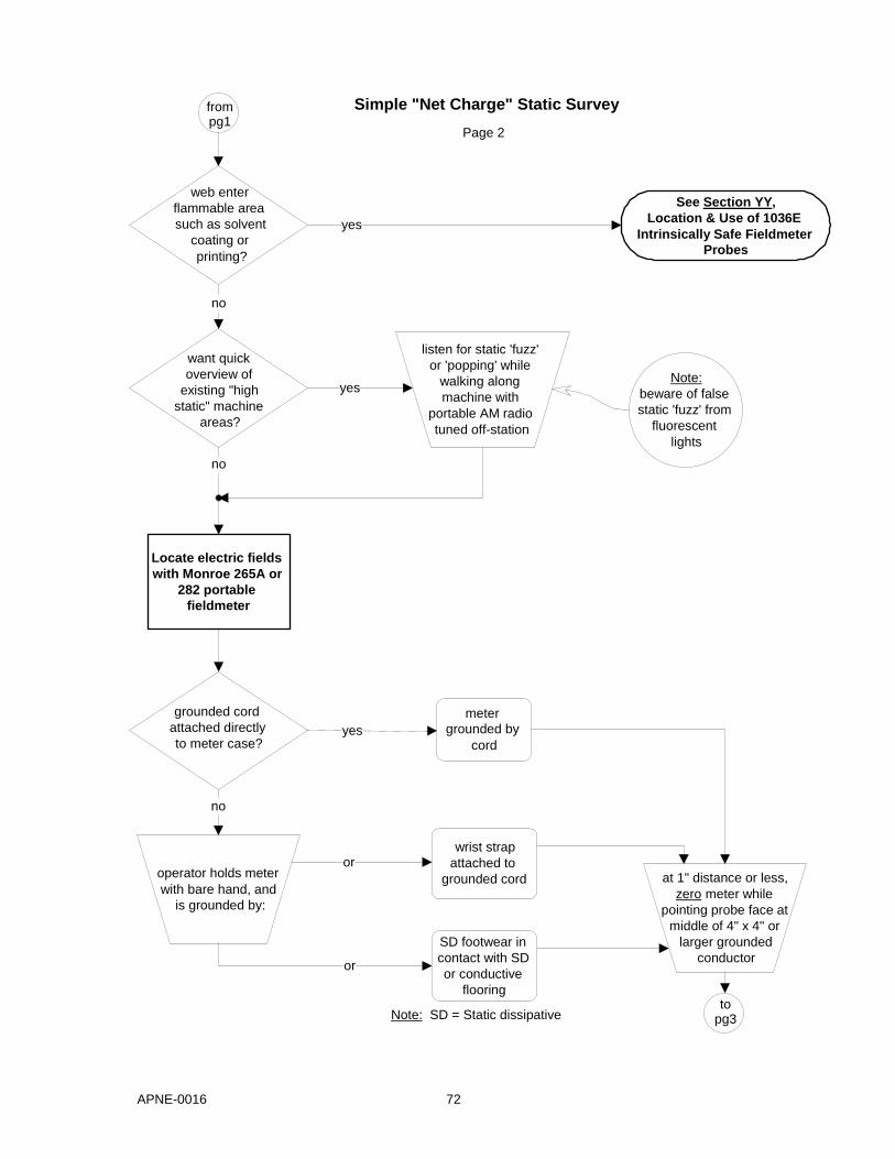
APNE-0016 72
web enter flammable area such as solvent
coating or printing?
want quick overview of
existing "high static" machine
areas?
Locate electric fields with Monroe 265A or
282 portable fieldmeter
from pg1
no
no
grounded cord attached directly to meter case?
Note: SD = Static dissipative
meter grounded by
cord yes
Simple "Net Charge" Static Survey
See Section YY , Location & Use of 1036E
Intrinsically Safe Fieldmeter Probes
yes
listen for static 'fuzz' or 'popping' while
walking along machine with
portable AM radio tuned off-station
yes Note:
beware of false static 'fuzz' from
fluorescent lights
to pg3
SD footwear in contact with SD or conductive
flooring
at 1" distance or less, zero meter while
pointing probe face at middle of 4" x 4" or larger grounded
conductor
wrist strap attached to
grounded cord operator holds meter with bare hand, and
is grounded by:
or
no
or
Page 2

APNE-0016 73
from pg2
Simple "Net Charge" Static Survey
approach web span to be measured,
monitoring meter reading
does meter reading
begin to exceed 20 kV/in at greater than 1"
probe-to-web spacing?
See Notes for Page 3 in preceding section
at 1" probe-to-web spacing, take
readings in free span
of web
Note 1: side of probe
at least 4" from closest ground
or charged insulator
Note 4: span location with no web flutter or
wobble Note 5: web target size at least 4" dia. (4d) with probe
at center
Note 2: web at least 10"
from closest ground opposite
probe
Note 3: no multiple web
spans in area
Finished
Stop! Possible static
discharge from web to fieldmeter
yes
no
Page 3

APNE-0016 74
Calculating Web Surface Charge Density
Providing that fieldmeter readings are taken in compliance with the limiting conditions specified above, web surface charge density (charge per unit area, q/A) can be calculated from these readings as follows [2,4]:
Surface charge density(σ) = Electric field(E) x Permittivity of free space(ε)
e.g. for a reading of 5,000 V/in:
σ (q/A) = {5,000 V/in} x {8.85 x 10⁻¹² coulomb(C)/volt(V)•meter(m)} or,
σ (q/A) = 1.74 x 10⁻⁶ C/m2, or 1.74 μC/m2 where: μ = 10-6
Relating Web Surface Charge Density To The Real World
It is widely reported in literature and texts that the maximum practical charge density a surface can hold is about 25 μC/m2. Discharges to nearby conductors and surrounding air are responsible for this limitation. It has been stated by Seaver [2] that “Industry has used an unwritten ‘rule-of-safety’, known as the 5000 Volts Rule, to keep static charge on a web at a reasonable level. The rule states that if the potential on a free-span of web is kept below 5000 volts, then the web should remain free of static discharge problems within that free-span. This rule was established when fieldmeters were usually specified to be
operated at 2.5 cm ( 1 inch) from the web.”
Referring to the charge density calculation in the previous section, where σ = 1.74 μC/m2 at E = 5000 V/in, Seaver [2] states “This charge density is over an order of magnitude below the 25 μC/m2 required for a guaranteed discharge from the web. Thus, the 5000 Volts Rule is equivalent to keeping the surface charge density below one tenth the discharge value.” and “The 5000 Volts Rule is a good safety rule for non-conductive webs, but it must be remembered that the measurement needs to be made with the fieldmeter held 2.5 cm from the surface of a true free-span of web. The 5000 Volts Rule ensures the web has a surface charge density that is less than 2 μC/m2.”
Lower charge levels, while safe from discharges, may still attract contaminants and cause contamination problems in many processes.
Continuous Monitoring Of Electric Fields In High-Risk Machine/Product Performance Areas
Antistatic measuring and control systems are needed in practice because the conditions for static elimination always change [10].
Permanent fieldmeters are especially necessary in hazardous areas to verify nonhazardous web surface charge density levels. The probes are installed immediately downstream of passive or active ionizers to make sure the ionizers are working correctly. This scenario assumes all rollers but the gravure and impression to be outside the classified area. All electrically powered equipment installed in these classified locations must be approved for the solvent atmosphere in which they are located, so both the probes and ionizers must be approved for the classified areas in which they are installed.
For details on continuous monitoring, see the next document in this series, APNE-0016, Static Control in Web Converting.
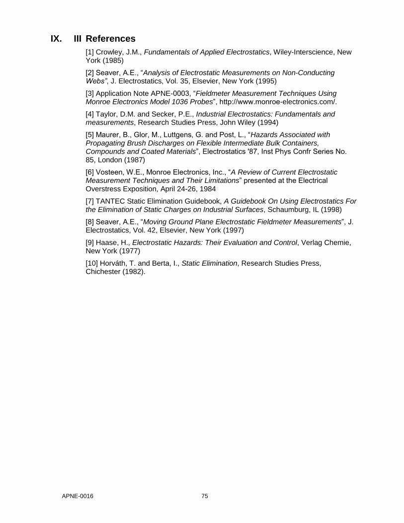
APNE-0016 75
IX. III References
[1] Crowley, J.M., Fundamentals of Applied Electrostatics, Wiley-Interscience, New York (1985)
[2] Seaver, A.E., “Analysis of Electrostatic Measurements on Non-Conducting Webs”, J. Electrostatics, Vol. 35, Elsevier, New York (1995)
[3] Application Note APNE-0003, “Fieldmeter Measurement Techniques Using Monroe Electronics Model 1036 Probes”, http://www.monroe-electronics.com/.
[4] Taylor, D.M. and Secker, P.E., Industrial Electrostatics: Fundamentals and measurements, Research Studies Press, John Wiley (1994)
[5] Maurer, B., Glor, M., Luttgens, G. and Post, L., “Hazards Associated with Propagating Brush Discharges on Flexible Intermediate Bulk Containers, Compounds and Coated Materials”, Electrostatics '87, Inst Phys Confr Series No. 85, London (1987)
[6] Vosteen, W.E., Monroe Electronics, Inc., “A Review of Current Electrostatic Measurement Techniques and Their Limitations” presented at the Electrical Overstress Exposition, April 24-26, 1984
[7] TANTEC Static Elimination Guidebook, A Guidebook On Using Electrostatics For the Elimination of Static Charges on Industrial Surfaces, Schaumburg, IL (1998)
[8] Seaver, A.E., “Moving Ground Plane Electrostatic Fieldmeter Measurements”, J. Electrostatics, Vol. 42, Elsevier, New York (1997)
[9] Haase, H., Electrostatic Hazards: Their Evaluation and Control, Verlag Chemie, New York (1977)
[10] Horváth, T. and Berta, I., Static Elimination, Research Studies Press, Chichester (1982).

APNE-0016 76
APPLICATION NOTE APNE-0016
Static Control in Web Converting
Table of Contents
I. Continuous Measurement and Control of Web Static Levels in Critical Machine Areas ..... 76
Content ............................................................................................................................. 76
Machine Grounding Hazard Elimination ............................................................................ 76
Machine Part Geometry Hazard Elimination ...................................................................... 76
Determining locations for continuous static control and monitoring in nonhazardous
areas using portable fieldmeters ............................................................................... 76
Hints for maximum static control and effective monitoring ................................................. 77
Determining locations for continuous static monitoring in hazardous (flammable) areas ... 77
Continuous tracking of fields in high-risk machine/product performance areas. ................. 77
II. Using Models 1036E and 1036F Electrostatic Fieldmeter Probes ..................................... 78
General ............................................................................................................................. 78
Installation ......................................................................................................................... 79
Servicing ......................................................................................................................... 141
Intrinsic Safety (IS) Barriers .............................................................................................. 83
III. Principle of Operation........................................................................................................ 84
IV. References ....................................................................................................................... 85
This Document .................................................................................................................. 85
General Fieldmeter References ........................................................................................ 85
Useful Hazardous (Classified) Location and Intrinsic Safety References........................... 86
V. Appendix A – Probe Connection Options .......................................................................... 87
General ............................................................................................................................. 87
Constructing Your Own Cables ......................................................................................... 88
VI. Appendix B – Intrinsic Safety Barriers ............................................................................... 92
General ............................................................................................................................. 92
Manufacturers of Approved IS Barriers ............................................................................. 92

APNE-0016 77
I. Continuous Measurement and Control of Web Static Levels in Critical Machine Areas
Content Control of static is not something that occurs once and can then be forgotten. It requires the implementation of continuous procedures such as charge neutralization using ionizers and electric field monitoring using permanent fieldmeters to verify that the ionizers are working effectively. Antistatic measuring and control systems are needed in practice because the conditions for static elimination always change [1].
This document is the third in a series of three application notes about static charging of materials and equipment in web converting machines, including recommendations for static measurement, control, and continuous monitoring. The first document in the series is APNE-0014 Electrostatic Charging In Web Converting and the second is APNE-0015 Electric Fields and Fieldmeters in Web Converting.
This document provides the reader, working in either hazardous or non-hazardous areas, with the practical tools necessary to determine where permanent static control devices and Monroe Electronics Model 1036 fieldmeter probes should be mounted on web converting machines. This document includes installation and usage instructions for the 1036 probes.
The reader should first attempt to minimize web charging by becoming familiar with Application Note APNE-0014 Electrostatic Charging In Web Converting before proceeding with the recommendations in this document.
Machine Grounding Hazard Elimination The most critical static control item to implement is electrical bonding and grounding of the web-processing machine. Unless intrinsically connected by virtue of construction (bolted together, gears with conductive grease, etc.), all conductive
1 parts on or near
2 the machine must be electrically
bonded together [3]. The bonding wires or straps should then be electrically grounded on both sides of the bonding run to prevent electrical isolation of conductive components in case a bond breaks. Proper grounding and bonding need to be checked by an electrician at least yearly, and after any mechanical work is done on the machine.
Machine Part Geometry Hazard Elimination Be careful to avoid incentive brush discharges
3 from a charged web to conductive machine parts in
hazardous areas due to part geometry. Brush discharges can occur in electric fields measured lower than 30 kV/cm at the web. These discharges are due to conductive protuberances or corners (e.g., those with an edge diameter of less than 10 mm) near the web, which concentrate the field to the 30 kV/cm breakdown strength of air [4].
Determining Locations For Continuous Static Control And Monitoring In Nonhazardous Areas Using Portable Fieldmeters To determine where static control devices and permanent static monitoring fieldmeter probes should be located, portable fieldmeters must first be used to determine the machine locations where fields are highest and need to be controlled (see APNE-0015 Electric Fields and Fieldmeters In Web Converting).
Passive and/or active ionizers (see Application Note APNE-0014 Electrostatic Charging In Web Converting) should be installed at the chosen locations and in the proper manner [3,5]. For high-speed or difficult-to-control operations, it may be necessary to install multiples of one or both type ionizers for complete static control.
Permanent fieldmeter probes (Monroe Model1036E or 1036F) then need to be installed downstream of the static control device(s) in critical locations to monitor their effectiveness.
1 A part is considered conductive if it is metal, or exhibits a volume resistivity less than 10
6 ohmcm [2].
2 A charged web can charge an ungrounded conductor by induction, setting up a spark risk to another conductor, including a human body.
3 A discharge between a conductor and an insulator that is often characterized by crackling without sparking.

APNE-0016 78
Hints For Maximum Static Control And Effective Monitoring High-speed operations might require a second static neutralizer along the web between some rollers to sufficiently reduce the web charge.
For web materials thinner than 50mil, one ionizer and fieldmeter should be able to neutralize and measure both sides of web. For web materials thicker than 50mil, an ionizer and fieldmeter may be needed for both sides of web. The only way to know for sure is to install an ionizer on one side of the web, and then measure the residual field on both sides of the web. If the non-ionized side exhibits a higher field than the ionized side, then both sides require neutralization, measurement, and control.
If all proper spacing requirements can be met for web materials thinner than 50mils, the fieldmeter probes should be mounted with the measurement aperture facing downward. This is necessary to minimize foreign material entering the sensitive probe aperture.
For optimal performance, static eliminators need to be positioned using fieldmeters to obtain the lowest readings, both for distance from the web as well as distance from the previous roller. This can best be done using permanently installed fieldmeter probes after the eliminators.
Determining Locations For Continuous Static Monitoring In Hazardous (Flammable) Areas As described in the section of this document Machine Grounding Hazard Elimination above, the most critical static control item to implement is effective grounding and bonding of conductive machine parts. Make sure conductive machine part shapes cannot also contribute to the static hazard problem by observing the recommendations in the section of this document, Machine Part Geometry Hazard Elimination. Then locate the general machine static monitoring positions as described in the section of this document Determining Locations For Continuous Static Control And Monitoring In Nonhazardous Araes Using Portable Fieldmeters.
Last, but most important, particular attention must be focused on the hazardous operations themselves. In a web converting process, these are usually flammable, solvent-based printing and other gravure operations, or coating, impregnating, and spreading operations. Charge neutralization devices should be installed after the web roller just prior to the hazardous operation roller. Additional devices should also be installed after the hazardous operation roller, and after each drying and turning roller in the hazardous rated area [3]. The devices installed in hazardous locations need to be rated Intrinsically Safe for the atmosphere in which they are placed.
Permanent fieldmeters should then be installed after each charge neutralization device to monitor its performance and indicate when maintenance on it is required.
Permanent fieldmeters are especially necessary in hazardous areas to verify that nonhazardous web surface charge density levels are maintained. The probes are installed downstream of passive or active ionizers to ensure that the ionizers are operating correctly. This scenario assumes that all rollers but gravure and impression to be outside the classified area. All electrically powered equipment installed in these classified locations must be approved for the solvent atmosphere in which they are located, so both the fieldmeter probes and the ionizers must be approved for the classified areas in which they are installed.
In hazardous locations, it is recommended that backup fieldmeters be installed, in case the primary fieldmeter at that position fails. Typically, one probe is located about one-third of the way across the web, and the other probe is located about two-thirds of the way across the web, attached to the same mounting bracket.
Continuous Monitoring Of Fields In High-Risk Machine/Product Performance Areas. Permanent Fieldmeter System. The Monroe Electronics Model 177A Static Monitor is a four-channel electrostatic fieldmeter. The Model 177A is the only system designed for long-term unattended monitoring of static levels in industrial environments. The Model 177A accepts up to four Model 1036E or Model1036F electric-field-sensing probes. The probes measure the electric field in the particular locations where they are installed, and they continuously monitor for electric field levels that may indicate safety hazards or quality concerns. The probes can be mounted up to 1000 feet from the Model 177A. Probes should be air purged for long-term stability.
Choice of locations for the probes is critical. Locations should be chosen based on an understanding of machine/process performance. Handheld fieldmeters are used to help characterize the machine and select locations (see APNE-0015 Electric Fields and Fieldmeters In Web Converting).

APNE-0016 79
Fieldmeters located immediately following active or passive charge control devices (ionizers) monitor the effectiveness of the devices.
Zeroing needs to be checked at least monthly to compensate for drift of the zero point. Model 1036 probe calibrations should be checked yearly during routine machine maintenance shutdowns. Monroe Electronics provides this probe calibration service.
The Model 177A Static Monitor includes programmable output alarms. If static levels in your application exceed your defined values, a first-level alarm is triggered to warn about the elevated static levels. The process is allowed to continue at this first (warning) level. If the problem is rectified and static levels return to normal, the first-level alarm is extinguished and the static monitor returns to a normal state.
If the problem persists and if the static levels rise to exceed a second-level (crucial) alarm, a second-level alarm is triggered. The second level alarm signal(s) can be used to shut down the operation until it is brought under control, or to further warn the operator of the more serious condition.
Consult the Model 177A Operator’s Manual for information about its features and operation. A full description of the operation of the Model 177A Static Monitor is contained in its operating manual. This information will not be repeated within this application note.
II. Using Models 1036E and 1036F Electrostatic Fieldmeter Probes
General Models 1036E and 1036F electrostatic fieldmeter probes are electrically identical and interchangeable. The major differences are physical. Model 1036F is a small (1.75” dia. x 1.25” H), lightweight version for general-purpose applications, or where available space is a problem. Model 1036E, for most industrial applications, is a 1036F probe built into a standard Crouse-Hinds ½”-FS1 electrical box with a stainless steel cover.
Both probes utilize the same vibrating capacitor modulator, and both have built-in provisions for purging with filtered air to prevent contamination and long-term drift. Inert gas can also be used for purging in hazardous areas where the probe will be used in an inert gas atmosphere. Purge gas flow in the Model 1036F exits only through the sensitive aperture in the gradient cap
4. Gas flow in Model
1036E is directed across the face of the gradient cap as well as through the sensitive aperture.
Typical applications are static level safety monitoring in flammable atmospheres, and static level quality monitoring in sensitive machine areas.
Figure II-1 Figure II-2
Model 1036E Fieldmeter Probe Model 1036F Fieldmeter Probe
4 The gradient cap is the reference surface of the fieldmeter probe that contains the aperture and that faces the target surface during measurements.
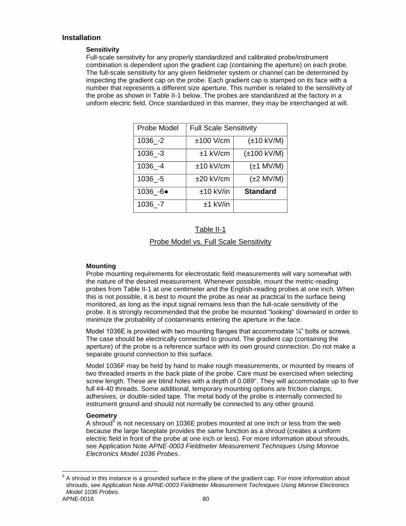
APNE-0016 80
Installation
Sensitivity Full-scale sensitivity for any properly standardized and calibrated probe/instrument combination is dependent upon the gradient cap (containing the aperture) on each probe. The full-scale sensitivity for any given fieldmeter system or channel can be determined by inspecting the gradient cap on the probe. Each gradient cap is stamped on its face with a number that represents a different size aperture. This number is related to the sensitivity of the probe as shown in Table II-1 below. The probes are standardized at the factory in a uniform electric field. Once standardized in this manner, they may be interchanged at will.
Probe Model Full Scale Sensitivity
1036_-2 ±100 V/cm (±10 kV/M)
1036_-3 ±1 kV/cm (±100 kV/M)
1036_-4 ±10 kV/cm (±1 MV/M)
1036_-5 ±20 kV/cm (±2 MV/M)
1036_-6● ±10 kV/in Standard
1036_-7 ±1 kV/in
Table II-1
Probe Model vs. Full Scale Sensitivity
Mounting Probe mounting requirements for electrostatic field measurements will vary somewhat with the nature of the desired measurement. Whenever possible, mount the metric-reading probes from Table II-1 at one centimeter and the English-reading probes at one inch. When this is not possible, it is best to mount the probe as near as practical to the surface being monitored, as long as the input signal remains less than the full-scale sensitivity of the probe. It is strongly recommended that the probe be mounted "looking" downward in order to minimize the probability of contaminants entering the aperture in the face.
Model 1036E is provided with two mounting flanges that accommodate ¼” bolts or screws. The case should be electrically connected to ground. The gradient cap (containing the aperture) of the probe is a reference surface with its own ground connection. Do not make a separate ground connection to this surface.
Model 1036F may be held by hand to make rough measurements, or mounted by means of two threaded inserts in the back plate of the probe. Care must be exercised when selecting screw length. These are blind holes with a depth of 0.089". They will accommodate up to five full #4-40 threads. Some additional, temporary mounting options are friction clamps, adhesives, or double-sided tape. The metal body of the probe is internally connected to instrument ground and should not normally be connected to any other ground.
Geometry A shroud
5 is not necessary on 1036E probes mounted at one inch or less from the web
because the large faceplate provides the same function as a shroud (creates a uniform electric field in front of the probe at one inch or less). For more information about shrouds, see Application Note APNE-0003 Fieldmeter Measurement Techniques Using Monroe Electronics Model 1036 Probes.
5 A shroud in this instance is a grounded surface in the plane of the gradient cap. For more information about shrouds, see Application Note APNE-0003 Fieldmeter Measurement Techniques Using Monroe Electronics Model 1036 Probes.
APNE-0016 81
As a truly uniform field does not usually occur in most practical measurement situations using the 1036F probes, partly due to the introduction of the grounded probe itself, one must either:
Improve the geometry by establishing a grounded plane (shroud) through which the fieldmeter probe can “view” the target surface,
Establish a correction factor for the data, or
Accept relative data. In many cases, this is an acceptable practice once a fixed geometry is established and that data is related to the real electric field.
Cables: Both Models 1036E and 1036F probes are normally equipped with 10-foot-long cables and subminiature D connectors, which mate with the Monroe Electronics Model 177A Static Monitor. This is Option 1 of six available wiring options. See Appendix A – Probe Connection Options for details. The first three options are for non-hazardous (non-classified) locations where there are no Intrinsic Safety (IS) considerations. The last three options are for hazardous (classified) locations where Intrinsic Safety must be considered as part of the installation.
Extension cables are available from Monroe Electronics in lengths up to 1000 feet, which is the maximum permissible length. These cables may be ordered in any length (up to 1000 feet) by part number 1036/12-nnnn, where nnnn is the length in feet.
The cable exit on the Model 1036E is through a packing gland that is screwed into a ½"-14 NPT tapped hole in a boss on one end of the housing. Inside the housing, the probe is plugged into a terminal block to which the cable attaches. Where it is desirable or necessary to connect Model 1036E probes to Model 177A Static Monitors using conduit, the original cable and packing gland can be removed and the cable replaced by any length (up to 1000 feet) pulled through the conduit. Refer to Appendix A – Probe Connection Options, Options 3, 4 or 6 (depending on whether Intrinsic Safety must also be considered) for details, including wiring information.
Purging Any contamination present in the probe or near the measurement will have an adverse affect on performance. When insulative particulate or liquid becomes charged and enters the probe or attaches near the aperture of the probe, it becomes a source of measurement error and drift. Less obvious is the influence of gaseous atmospheric constituents, including aerosols, which contaminate the probe by altering the contact potentials
6 between critical surfaces.
Constant purging of the Model 1036 probe with clean dry air or an inert gas is recommended whenever practicable to prevent airborne contaminants from entering the aperture in the gradient cap and being deposited on the electrode.
The air supply should meet standard ANSI/ISA-7.0.01-1996 - Quality Standard for Instrument Air. A Koby "Junior" filter available from Koby, Inc., 299 Lincoln Street, Marlboro, MA 01752 should meet this standard and will provide sufficient mechanical and chemical filtration for up to four probes under most conditions.
A complete probe purge kit, Model 1017/22G, is available for the Model 1036F from Monroe Electronics. It includes a low volume, long-life air pump, mechanical and chemical filters, and a supply of tubing. The pump is fully capable of 24-hour-per-day operation, thus keeping the probe ready for immediate use. A purge gas inlet tube supplied with each 1036F probe may be installed in either of two positions, the choice of which is primarily a matter of convenience in routing of the hose carrying the purge gas. These consist of tapped holes that exit at 90° to each other near the probe cable. If it is desired to move the purge tube to the other location, simply switch the purge tube with the Allen set screw plugging the other hole.
6 Contact potential between two conductors is caused by their different work functions, which are the energies
needed to remove an electron from the conductor. This gives rise to a potential (voltage) difference. This energy is affected by the properties of the surface region. Thus, the work function is very sensitive to surface conditioning, contamination, etc.
APNE-0016 82
Purge the Model 1036E probe through a ¼"-18 NPT tapped hole in the end of the housing near the cable exit using common plumbing or tubing components.
Gas pressure to either probe type should be only great enough to produce a slight positive flow out of the probe and in no event should it exceed a pressure of ½ psi.
Servicing
General It must be emphasized that the critical elements of these probes (gradient cap and sensing electrode) must be kept free from contaminants, e.g., dust, fumes, mists, or any foreign material. The materials of which these elements are made were very carefully chosen to minimize contact potential. Any foreign matter that will cause relative electrical activity when combined with relative motion will tend to cause drift and measurement errors.
Therefore, it is recommended that:
Probes be constantly purged even when not in use, if this is practical.
Probes be kept tightly covered when not in use and are not being purged to prevent contamination. A covering such as a plastic bag or aluminum foil may be used. DO NOT cover the sensitive aperture with adhesive tape.
Probes be cleaned only to the degree and frequency necessary to achieve the required stability.
Gradient caps NOT be removed for cleaning unless absolutely necessary.
Major cleaning and reconditioning be performed by the factory.
Cleaning The recommended cleaning solvent is clean 70-100% isopropyl alcohol applied with a suitable soft, lint-free applicator. Use of a non-approved solvent may degrade performance permanently, requiring factory service.
Outside surfaces of the probe should first be wiped clean with a lint-free wiping tissue saturated in solvent. Then the interior surfaces should be flushed with solvent, using a plastic squeeze bottle
7, through the aperture until no dirt or dust may be seen. The probe
should then be allowed to drain and dry thoroughly. A 15-minute bake-out at 75°C is recommended to remove residual solvent.
Model 1036E Disassembly/Assembly In order to rewire the cable terminal block, replace, or standardize the probe assembly, it must first be removed from its housing. This is done by loosening the four crosspoint screws around the outer edge of the cover 1-1½ turns each, in turn, several times while lifting the cover and probe straight out of the housing until it is completely removed. DO NOT attempt to remove the screws completely one at a time. These four screws have circular "E-rings" installed on them under the cover plate to make the screws captive and prevent their falling into machinery below.
The probe assembly will need to be removed from the cover plate on the bench for standardization, calibration, or to replace the gradient cap. This is done by removing the four crosspoint screws that secure the phenolic mounting block to the hex standoffs, leaving the standoffs attached to the cover plate.
To reassemble the probe unit, essentially reverse the above procedure. Once the phenolic mounting block has been secured to the four hex standoffs, the probe unit should be inspected to assure that an even gap exists completely around the gradient cap between the gradient cap and the cover plate. If not, loosen the two crosspoint screws that secure the probe body to the phenolic mounting block, and adjust the probe body so that it is centered and completely surrounded by an even air gap.
Partially mate the card-edge fingers into the terminal block connector in the housing and tighten the four outer screws in the cover plate 1-1½ turns at a time until the assembly is secured in the housing.
7 Soft plastic wash bottles with an attached nozzle are available from scientific supply distributors.
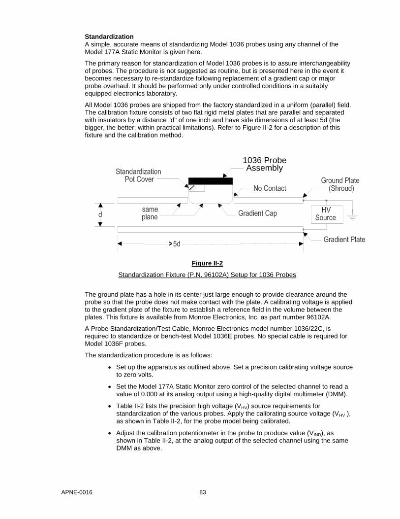
APNE-0016 83
Standardization A simple, accurate means of standardizing Model 1036 probes using any channel of the Model 177A Static Monitor is given here.
The primary reason for standardization of Model 1036 probes is to assure interchangeability of probes. The procedure is not suggested as routine, but is presented here in the event it becomes necessary to re-standardize following replacement of a gradient cap or major probe overhaul. It should be performed only under controlled conditions in a suitably equipped electronics laboratory.
All Model 1036 probes are shipped from the factory standardized in a uniform (parallel) field. The calibration fixture consists of two flat rigid metal plates that are parallel and separated with insulators by a distance "d" of one inch and have side dimensions of at least 5d (the bigger, the better; within practical limitations). Refer to Figure II-2 for a description of this fixture and the calibration method.
Figure II-2
Standardization Fixture (P.N. 96102A) Setup for 1036 Probes
The ground plate has a hole in its center just large enough to provide clearance around the probe so that the probe does not make contact with the plate. A calibrating voltage is applied to the gradient plate of the fixture to establish a reference field in the volume between the plates. This fixture is available from Monroe Electronics, Inc. as part number 96102A.
A Probe Standardization/Test Cable, Monroe Electronics model number 1036/22C, is required to standardize or bench-test Model 1036E probes. No special cable is required for Model 1036F probes.
The standardization procedure is as follows:
Set up the apparatus as outlined above. Set a precision calibrating voltage source to zero volts.
Set the Model 177A Static Monitor zero control of the selected channel to read a value of 0.000 at its analog output using a high-quality digital multimeter (DMM).
Table II-2 lists the precision high voltage (VHV) source requirements for standardization of the various probes. Apply the calibrating source voltage (VHV ), as shown in Table II-2, for the probe model being calibrated.
Adjust the calibration potentiometer in the probe to produce value (VIND), as shown in Table II-2, at the analog output of the selected channel using the same DMM as above.
1036 ProbeAssembly
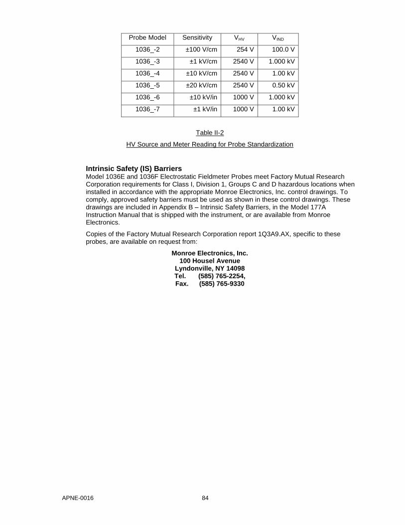
APNE-0016 84
Probe Model Sensitivity VHV VIND
1036_-2 ±100 V/cm 254 V 100.0 V
1036_-3 ±1 kV/cm 2540 V 1.000 kV
1036_-4 ±10 kV/cm 2540 V 1.00 kV
1036_-5 ±20 kV/cm 2540 V 0.50 kV
1036_-6 ±10 kV/in 1000 V 1.000 kV
1036_-7 ±1 kV/in 1000 V 1.00 kV
Table II-2
HV Source and Meter Reading for Probe Standardization
Intrinsic Safety (IS) Barriers Model 1036E and 1036F Electrostatic Fieldmeter Probes meet Factory Mutual Research Corporation requirements for Class I, Division 1, Groups C and D hazardous locations when installed in accordance with the appropriate Monroe Electronics, Inc. control drawings. To comply, approved safety barriers must be used as shown in these control drawings. These drawings are included in Appendix B – Intrinsic Safety Barriers, in the Model 177A Instruction Manual that is shipped with the instrument, or are available from Monroe Electronics.
Copies of the Factory Mutual Research Corporation report 1Q3A9.AX, specific to these probes, are available on request from:
Monroe Electronics, Inc. 100 Housel Avenue
Lyndonville, NY 14098 Tel. (585) 765-2254, Fax. (585) 765-9330
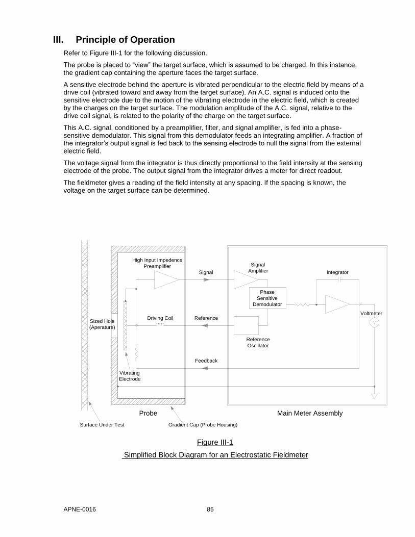
APNE-0016 85
III. Principle of Operation
Refer to Figure III-1 for the following discussion.
The probe is placed to “view” the target surface, which is assumed to be charged. In this instance, the gradient cap containing the aperture faces the target surface.
A sensitive electrode behind the aperture is vibrated perpendicular to the electric field by means of a drive coil (vibrated toward and away from the target surface). An A.C. signal is induced onto the sensitive electrode due to the motion of the vibrating electrode in the electric field, which is created by the charges on the target surface. The modulation amplitude of the A.C. signal, relative to the drive coil signal, is related to the polarity of the charge on the target surface.
This A.C. signal, conditioned by a preamplifier, filter, and signal amplifier, is fed into a phase-sensitive demodulator. This signal from this demodulator feeds an integrating amplifier. A fraction of the integrator’s output signal is fed back to the sensing electrode to null the signal from the external electric field.
The voltage signal from the integrator is thus directly proportional to the field intensity at the sensing electrode of the probe. The output signal from the integrator drives a meter for direct readout.
The fieldmeter gives a reading of the field intensity at any spacing. If the spacing is known, the voltage on the target surface can be determined.
Figure III-1
Simplified Block Diagram for an Electrostatic Fieldmeter
Phase
Sensitive
Demodulator
Signal
Amplifier
Reference
Oscillator
Integrator
Voltmeter
High Input Impedence
Preamplifier
Signal
Reference
Feedback
Surface Under Test Gradient Cap (Probe Housing)
Sized Hole
(Aperature)
Vibrating
Electrode
Main Meter AssemblyProbe
Driving Coil
APNE-0016 86
IV. References
This Document
[1] Horváth, T. and Berta, I., Static Elimination, Research Studies Press, Chichester (1982).
[2] ESD STM11.12-2000: Volume Resistance Measurement of Static Dissipative Planar Materials, ESD Association, Rome, NY (2000)
[3] NFPA 77: Recommended Practice on Static Electricity, 2000 Edition, National Fire Protection Association, Quincy, MA (2000).
[4] ] Walmsley, H.L., “Avoidance of Electrostatic Hazards in the Petroleum Industry”, J. Electrostatics, Vol. 27, No. 1 & No. 2, Elsevier, New York (1992)
[5] TANTEC Static Elimination Guidebook, A Guidebook On Using Electrostatics For the Elimination of Static Charges on Industrial Surfaces, Schaumburg, IL (1998)
General Fieldmeter References The following references are available from Monroe Electronics, Inc.
“Standards Related to Static Electricity”, www.monroe-electronics.com/esd_appntspdf/apne-0001.pdf
“Fieldmeter Measurement Techniques Using Monroe Electronics Model 1036 Probes”, www.monroe-electronics.com/esd_appntspdf/apne-0003.pdf
WILLIAM E. VOSTEEN, Monroe Electronics, Inc., "A Review of Current Electrostatic Measurement Techniques and their Limitations" Presented at the ELECTRICAL OVERSTRESS EXPOSITION, April 24-26,1984.
LT 18: MARK BLITSHTEN, The Simco Company, Inc., "Measuring the Electric Field of Flat Surfaces with Electrostatic Fieldmeters" Presented at the ELECTROSTATICS SOCIETY OF AMERICA CONFERENCE ON ELECTROSTATICS, June 20-22, 1984.
LT 21: R.G. CUNNINGHAM, Eastman Kodak Co., "Use of Fieldmeters for Charge Measurements on Moving Webs" in 1975 ANNUAL REPORT. CONFERENCE ON ELECTRICAL INSULATION AND DIELECTRIC PHENOMENA, NATIONAL ACADEMY OF SCIENCES pp. 13-20, 1978.
LT 22: A. VAN ROGGEN, E.I. du Pont de Nemours & Company, "The Use of Electric Field Meters for Precision Measurements" in 1972 ANNUAL REPORT. CONFERENCE ON ELECTRICAL INSULATION AND DIELECTRIC PHENOMENA, NATIONAL ACADEMY OF SCIENCES, pp. 9-16, 1973.
LT 25: Monroe Electronics, Inc., "Guide to Monroe Electronics Electrostatic Fieldmeters"
APNE-0016 87
Useful Hazardous (Classified) Location and Intrinsic Safety References American National Standards Institute (ANSI) and International Society for Measurement and Control (ISA)
ISA-12.00.01-1999 (IEC 60079-0 Mod) Electrical Apparatus for Use in Class I, Zones 0 & 1 Hazardous (Classified) Locations - General Requirements
ISA-12.01.01-1999 Definitions and Information Pertaining to Electrical Instruments in Hazardous (Classified) Locations
ISA-12.02.01-1999 (IEC 60079-11 Mod) Electrical Apparatus for Use in Class I, Zones 0, 1, & 2 Hazardous (Classified) Locations - Intrinsic Safety Requirements
ANSI/ISA-RP12.6-1995 Wiring Practices for Hazardous (Classified) Locations Instrumentation Part I: Intrinsic Safety
ANSI/ISA-TR12.24.01-1998 (IEC 79-10 Mod) Recommended Practice for Classification of Locations for Electrical Installations Classified as Class I, Zone 0, Zone 1, or Zone 2
ISA PO Box 12277, 67 Alexander Drive Research Triangle Park, NC 27709 Telephone: 919-549-8411 Fax: 919-549-8288 E-Mail: [email protected]
National Fire Prevention Association (NFPA)
NFPA 34: Standard for Dipping and Coating Processes Using Flammable or Combustible Liquids
NFPA 77: Recommended Practice on Static Electricity
NFPA 325: Guide to Fire Hazard Properties of Flammable Liquids, Gases, and Volatile Solids
NFPA 497: Classification of Flammable Liquids, Gases, or Vapors and of Hazardous (Classified) Locations for Electrical Installations in Chemical Process Areas
Electrical Installations in Hazardous Locations
National Fire Protection Association 1 Batterymarch Park PO Box 9101 Quincy, MA 02269-9101 Tel: (800) 344-3555 Fax: (617) 770-0700 Email: [email protected]
APNE-0016 88
V. Appendix A – Probe Connection Options
General Model 1036E or 1036E Probes may be wired to the Model 177A Static Monitor in at least six different ways. The first 3 options are for non-hazardous (non-classified) locations where there are no Intrinsic Safety (IS) considerations. The last 3 options are for hazardous (classified) locations where Intrinsic Safety must be considered as part of the installation.
Option 1: Probes (1036E or 1036F) use factory installed cables; no extension cables; no Intrinsic Safety considerations
Probes are normally factory equipped with ten-foot-long cables, although longer or shorter cables are available on special order. To use or test this system, simply plug the probes into the appropriate connectors on the back of the Model 177A.
Option 2: Probes (1036E or 1036F) use factory installed cables and factory supplied extension cables; no Intrinsic Safety considerations
Extension cables are available in lengths up to 1000 feet. The extension cable part number is 1036/12-nnnn, where nnnn denotes the length of the cable in feet. Factory supplied extension cables will be labeled with this part number near one end.
The extension cable female connector mates with the 1036 probe cable male connector, and the extension cable male connector mates with the female connector on the back of the Model 177A.
Although it is virtually impossible to err, it is advisable to test the system "on the bench" before permanently installing long cable runs.
Option 3: 1036E probes with long customer installed cables, with or without extension cables (factory or customer supplied); no Intrinsic Safety considerations
This option does not apply to 1036F probes, which have permanently attached cables.
Wiring connections for customer installed 1036E probe cables for use in a non-IS installation are shown in Figure V-1. Wiring connections for customer supplied extension cables for use in a non-IS installation are shown in Figure V-2. Model 1036E probes have terminal blocks inside their housings to which the cable wires are directly attached.
As in Option 2, it is advisable to "bench test" the system before removing the factory-attached cables to ensure it is working properly. It is also advisable to test the system "on the bench" after attaching the customer-installed cables, with any extension cables, before permanently installing long cable runs.
Option 4: 1036E probes with factory installed cables, extension cables (factory or customer supplied) and Intrinsic Safety barriers
Refer to drawing 1036/10 [SHT. 2 of 3] in the Model 177A Instruction Manual. This drawing shows wiring for one channel. Generally, all channels are wired alike. All barriers (four per channel) may be located in a single barrier enclosure.
Note that on each side of the barrier enclosure) you have the option of using connectors or "hard wiring" the cables directly to terminals on each barrier. Hard wiring allows the cables to be pulled through conduit without interference associated with connectors. Model 1036E probes have terminal blocks inside their housings to which the cable wires are directly attached. Wiring details for customer supplied extension cables are shown in Figure V-2.
As in the previous options, it is advisable to test the system "on the bench" after attaching the customer installed cables, with any extension cables, before permanently installing long cable runs.
APNE-0016 89
Option 5: 1036F probes with factory installed cables, extension cables (factory or customer supplied) and Intrinsic Safety barriers
Refer to drawing 1036/10 [SHT. 3 of 3] in the Model 177A Instruction Manual. This drawing shows wiring for one channel. Generally, all channels are wired alike. All barriers (four per channel) may be located in a single barrier enclosure.
Note that (on each side of the barrier enclosure) you have the option of using connectors or "hard wiring" the cables directly to terminals on each barrier. Hard wiring allows the cables to be pulled through conduit without interference associated with connectors. Wiring details for customer supplied extension cables are shown in Figure V-2.
As in the previous options, it is advisable to test the system "on the bench" after attaching the extension cables before permanently installing long cable runs.
Option 6: 1036E probes with customer installed cables, extension cables (factory or customer supplied) and Intrinsic Safety barriers
Refer to drawing 1036/10 [SHT. 1 of 3] in the Model 177A Instruction Manual. This drawing shows wiring for one channel. Generally, all channels are wired alike. All barriers (four per channel) may be located in a single barrier enclosure.
Note that (on each side of the barrier enclosure) you have the option of using connectors or "hard wiring" the cables directly to terminals on each barrier. Model 1036E probes have terminal blocks inside their housings to which the cable wires are directly attached. Hard wiring allows the cables to be pulled through conduit without interference associated with connectors. Wiring details for customer installed 1036E probe cables are shown in Figure V-1. Wiring details for customer supplied extension cables are shown in Figure V-2.
It is advisable to "bench test" the system before removing the factory-attached cables to ensure it is working properly. As in the previous options, it is advisable to test the system "on the bench" after attaching the customer installed cables, with any extension cables, before permanently installing long cable runs.
Constructing Your Own Cables
There are a couple of reasons why you may want to construct your own cables:
1. To save money.
You may be able to save money if everything goes OK. However, troubleshooting may prove to be more costly in the end than using factory supplied cables.
2. Conduit must be used for cable runs, but cable connectors won't fit through conduit you normally use.
The largest rectangular cross sectional dimensions of each connector are ⅝" x 1¼". The minimum conduit ID through which this can be pulled is 1⅜". However, it is possible, with a great deal of care, to pull up to five cables simultaneously through that ID in a smooth straight run by staggering the connectors.
There are a couple different approaches for constructing your own cables to fit through your conduit:
1. Buy factory extension cables and modify them.
Cable construction details for 1036E probes with customer installed cables are provided in Figure V-1. This option does not apply to 1036F probes, which have permanently attached cables.
Extension cables are available in lengths up to 1000 feet. The extension cable part
APNE-0016 90
number is 1036/12-nnnn, where nnnn denotes the length of the cable in feet. Factory supplied extension cables will be labeled with this part number near one end. The cables need to be long enough to reach from the console location, through the conduit, and to the probe location with a few feet extra for measurement error.
Remove and discard the factory supplied (usually ten-foot) cable from the probe (Model 1036E only), and mount the probe housing at the measurement location.
Cut the female DB9 connector plug off the extension cable.
Pull the cable from the IS Barrier and/or Model 177 instrument end of the conduit to the probe end.
2. Buy bulk cable and connect both ends manually.
Cable construction details for 1036E probes with customer installed cables are provided in Figure V-1. This option does not apply to 1036F probes, which have permanently attached cables.
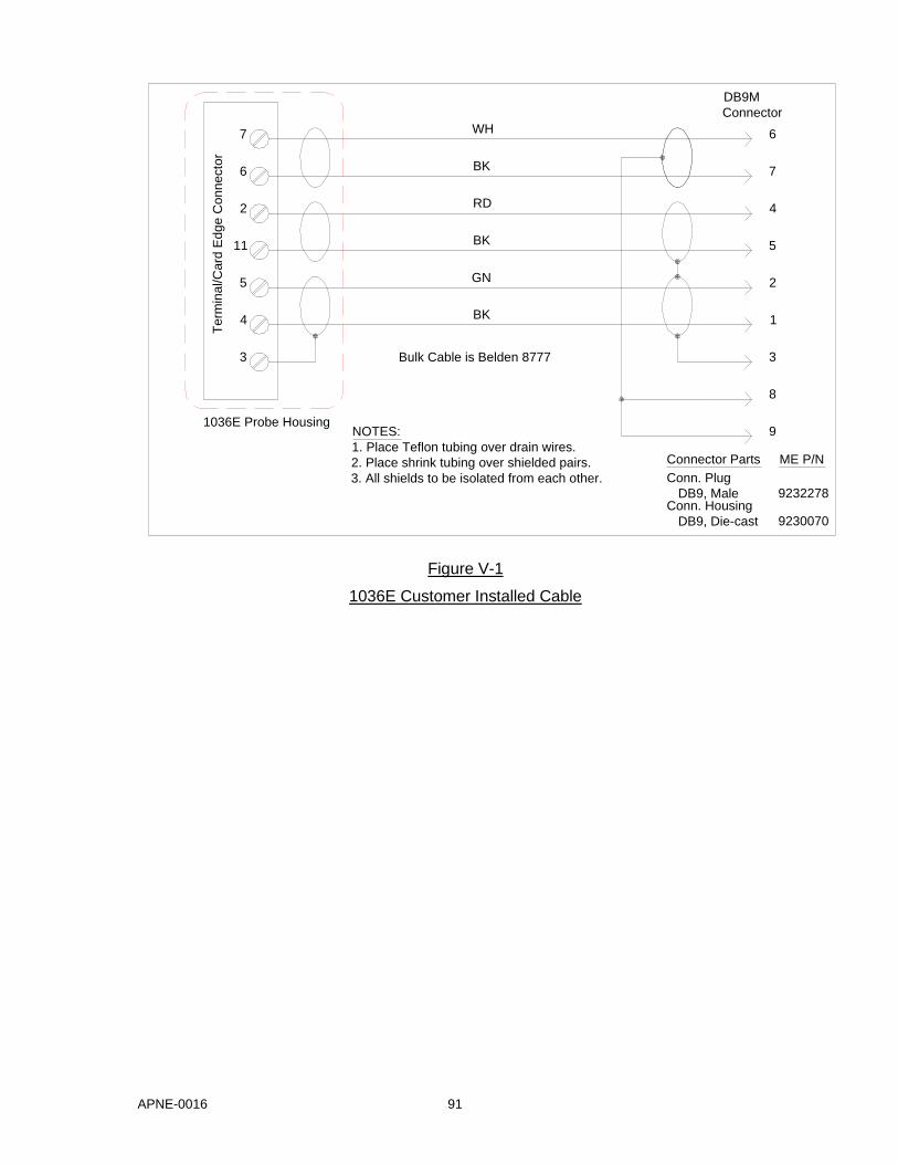
APNE-0016 91
Figure V-1
1036E Customer Installed Cable
Te
rmin
al/C
ard
Ed
ge
Co
nn
ecto
r
WH
BK
RD
BK
GN
BK
6
5
3
4
11
2
7
1036E Probe Housing
Bulk Cable is Belden 8777
NOTES:
1. Place Teflon tubing over drain wires.
2. Place shrink tubing over shielded pairs.
3. All shields to be isolated from each other.
Conn. Housing
DB9, Die-cast
Connector Parts
Conn. Plug
DB9, Male
9230070
9232278
ME P/N
9
8
DB9M
Connector
7
2
3
1
5
4
6
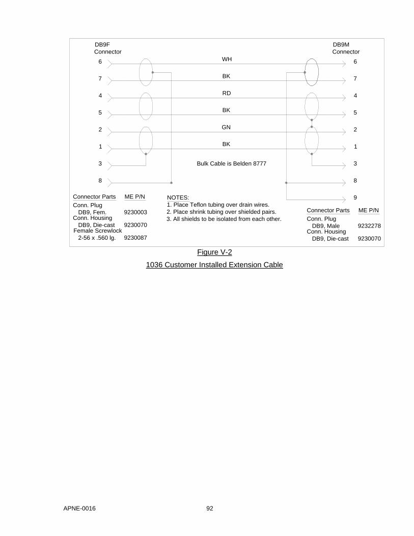
APNE-0016 92
Figure V-2
1036 Customer Installed Extension Cable
WH
DB9M
Connector
6
7
4
5
2
1
9
BK
RD
BK
GN
BK
3
8
Bulk Cable is Belden 8777
Connector Parts
Conn. Plug
DB9, MaleConn. Housing
DB9, Die-cast
ME P/N
9232278
9230070
NOTES:
1. Place Teflon tubing over drain wires.
2. Place shrink tubing over shielded pairs.
3. All shields to be isolated from each other.
8
3
2
5
4
7
6
1
DB9F
Connector
ME P/N
9230070
9230003
Conn. Plug
DB9, Fem.Conn. Housing
DB9, Die-cast
Connector Parts
Female Screwlock
2-56 x .560 lg. 9230087
APNE-0016 93
VI. Appendix B – Intrinsic Safety Barriers
General
Model 1036E and 1036F Electrostatic Fieldmeter Probes meet Factory Mutual Research Corporation requirements for Class I, Division 1, Groups C and D hazardous locations when installed in accordance with the appropriate Monroe Electronics, Inc. control drawings included in this document. Approved safety barriers must be used as shown in the drawings to comply.
Copies of the Factory Mutual Research Corporation report 1Q3A9.AX specific to these probes are available on request from:
Monroe Electronics, Inc. 100 Housel Avenue
Lyndonville, NY 14098 Tel. (716) 765-2254 Fax. (716) 765-9330
Manufacturers of Approved IS Barriers
Two manufacturers of IS barriers are currently approved:
MTL, Incorporated and R. Stahl, Inc. 8576 Wellington Road 150 New Boston St. PO Box 1690 Woburn, MA 01801-6204 Manassas, VA 22110-1690 Tel. (703) 361-0111 Tel. (617) 933-1844 Fax. (703) 368-1029 Fax. (617) 933-7896
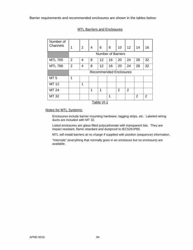
APNE-0016 94
Barrier requirements and recommended enclosures are shown in the tables below:
MTL Barriers and Enclosures
Number of Channels
1
2
4
6
8
10
12
14
16
Number of Barriers
MTL 765 2 4 8 12 16 20 24 28 32
MTL 766 2 4 8 12 16 20 24 28 32
Recommended Enclosures
MT 5 1
MT 12 1
MT 24 1 1 2 2
MT 32 1 2 2
Table VI-1
Notes for MTL Systems:
Enclosures include barrier mounting hardware, tagging strips, etc. Labeled wiring ducts are included with MT 32.
Listed enclosures are glass-filled polycarbonate with transparent lids. They are impact resistant, flame retardant and dustproof to IEC529:IP65.
MTL will install barriers at no charge if supplied with position (sequence) information.
"Internals" (everything that normally goes in an enclosure but no enclosure) are available.
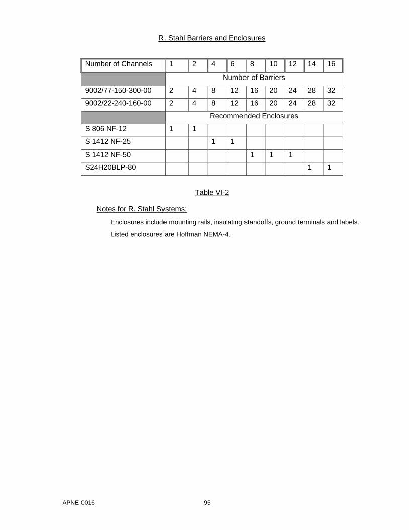
APNE-0016 95
R. Stahl Barriers and Enclosures
Number of Channels 1 2 4 6 8 10 12 14 16
Number of Barriers
9002/77-150-300-00 2 4 8 12 16 20 24 28 32
9002/22-240-160-00 2 4 8 12 16 20 24 28 32
Recommended Enclosures
S 806 NF-12 1 1
S 1412 NF-25 1 1
S 1412 NF-50 1 1 1
S24H20BLP-80 1 1
Table VI-2
Notes for R. Stahl Systems:
Enclosures include mounting rails, insulating standoffs, ground terminals and labels.
Listed enclosures are Hoffman NEMA-4.