Embed Size (px)
DESCRIPTION
Multi Mode BTS
Citation preview

SRAN3.0 3900 Series Multi-Mode Base Station
Product Description
Issue V1.4
Date 2010-08-15
HUAWEI TECHNOLOGIES CO., LTD.

SRAN3.0
3900 Series Multi-Mode Base Station Product Description
Issue V1.4 (2010-08-15) Huawei Proprietary and Confidential Copyright © Huawei Technologies Co., Ltd.
Page 2 of 66
Copyright © Huawei Technologies Co., Ltd. 2010. All rights reserved. No part of this document may be reproduced or transmitted in any form or by any means without prior written consent of Huawei Technologies Co., Ltd. Trademarks and Permissions
and other Huawei trademarks are trademarks of Huawei Technologies Co., Ltd. All other trademarks and trade names mentioned in this document are the property of their respective holders. Notice The purchased products, services and features are stipulated by the commercial contract made between Huawei and the customer. All or partial products, services and features described in this document may not be within the purchased scope or the usage scope. Unless otherwise agreed by the contract, all statements, information, and recommendations in this document are provided “AS IS” without warranties, guarantees or representations of any kind, either express or implied.
The information in this document is subject to change without notice. Every effort has been made in the preparation of this document to ensure accuracy of the contents, but all statements, information, and recommendations in this document do not constitute the warranty of any kind, express or implied.
Huawei Technologies Co., Ltd.
Address: Huawei Industrial Base Bantian, Longgang Shenzhen 518129 People's Republic of China
Website: http://www.huawei.com
Email: [email protected]

SRAN3.0
3900 Series Multi-Mode Base Station Product Description
Issue V1.4 (2010-08-15) Huawei Proprietary and Confidential Copyright © Huawei Technologies Co., Ltd.
Page 3 of 66
Contents
1 Introduction....................................................................................................................................5 1.1 Positioning .......................................................................................................................................................5 1.2 Benefits ............................................................................................................................................................6
2 Architecture ....................................................................................................................................9 2.1 Overview..........................................................................................................................................................9 2.2 BBU3900 .......................................................................................................................................................10
2.2.1 Appearance of the BBU3900 ................................................................................................................10 2.2.2 Logical Structure of the BBU3900........................................................................................................10 2.2.3 Boards of the BBU3900........................................................................................................................12 2.2.4 Ports on the BBU3900 ..........................................................................................................................14
2.3 RRU3908 .......................................................................................................................................................16 2.3.1 Appearance of the RRU3908 ................................................................................................................16 2.3.2 Ports on the RRU3908 ..........................................................................................................................16 2.3.3 Typical Configuration of RRU3908......................................................................................................18
2.4 MRFU ............................................................................................................................................................22 2.4.1 Appearance of the MRFU .....................................................................................................................22 2.4.2 Ports on the MRFU ...............................................................................................................................22 2.4.3 Typical Configuration of MRFU...........................................................................................................23
2.5 Power Sharing ................................................................................................................................................25 2.6 Auxiliary Devices...........................................................................................................................................32
2.6.1 BTS3900 Cabinet..................................................................................................................................32 2.6.2 BTS3900L Cabinet ...............................................................................................................................33 2.6.3 RFC.......................................................................................................................................................34 2.6.4 APM30H ...............................................................................................................................................35 2.6.5 TMC11H ...............................................................................................................................................36 2.6.6 IBBS200T .............................................................................................................................................36 2.6.7 IBBS200D.............................................................................................................................................37 2.6.8 PS4890..................................................................................................................................................37
3 Products and Application Scenarios .......................................................................................39 3.1 Overview........................................................................................................................................................39 3.2 Application Scenarios.....................................................................................................................................39
3.2.1 Application Scenarios of the DBS3900.................................................................................................39

SRAN3.0
3900 Series Multi-Mode Base Station Product Description
Issue V1.4 (2010-08-15) Huawei Proprietary and Confidential Copyright © Huawei Technologies Co., Ltd.
Page 4 of 66
3.2.2 Application Scenarios of the BTS3900 .................................................................................................41 3.2.3 Application Scenarios of the BTS3900A ..............................................................................................42 3.2.4 Application Scenarios of the BTS3900L...............................................................................................45
4 Technical Specification..............................................................................................................47 4.1 Technical Specifications of the DBS3900 ......................................................................................................47 4.2 Technical Specifications of the BTS3900 ......................................................................................................52 4.3 Technical Specifications of the BTS3900A....................................................................................................56 4.4 Technical Specifications of the BTS3900L ....................................................................................................60
A Acronyms and Abbreviations..................................................................................................65

SRAN3.0
3900 Series Multi-Mode Base Station Product Description
Issue V1.4 (2010-08-15) Huawei Proprietary and Confidential Copyright © Huawei Technologies Co., Ltd.
Page 5 of 66
1 Introduction
1.1 Positioning With the mobile communications technology advancing rapidly, the focus of the mobile operators during network construction and partner selection rests on innovation and integration of multiple technologies. This approach helps the mobile operators in constructing a cost-effective and future-oriented mobile network.
The launch of the 3900 series multi-mode base stations effectively drives the development of the mobile network, presenting a network with concepts of "Convergence, Broadband, Green, and Evolution" and aiding operators in constructing a better future-oriented mobile network.
Upholding the concept of continuous innovation based on customer requirements, Huawei unveils the 3900 series multi-mode base stations, a future-oriented network solution integrating radio resources and multiple technologies. The design of the 3900 series multi-mode base stations are based on originality that encompasses the latest chip design, system architecture, Power Amplifier (PA) technology, and power consumption management.
The 3900 series multi-mode base stations feature the cutting-edge modular design of multiple modes and forms. The three basic modules of the 3900 series multi-mode base stations are characterized by small size, high integration, low power consumption, and easy and fast deployment.
The innovative design and flexible combinations of the function modules and auxiliary devices encourage Huawei to diversify multi-mode base station products. Furthermore, operators can install modules of different modes in one cabinet to form multiple base station products adapting to different scenarios. This accelerates introduction of new frequency bands and radio technologies and effectively addresses the requirements for a multi-mode mobile network..
The 3900 series multi-mode base stations, based on IP switch and multi-carrier technologies, support bandwidth of over 100 Mbit/s at transmission ports. This ensures the compatibility with the growing mobile data services and ensures higher data transmission rates for users.
The optimized hardware and system architecture of the 3900 series multi-mode base stations, in addition to the innovative technologies for the PA and power consumption management, enable operators to implement energy saving and emission reduction and to construct a green communication network through temperature control and green energy utilization.

SRAN3.0
3900 Series Multi-Mode Base Station Product Description
Issue V1.4 (2010-08-15) Huawei Proprietary and Confidential Copyright © Huawei Technologies Co., Ltd.
Page 6 of 66
1.2 Benefits The 3900 series multi-mode base stations adopt the cutting-edge modular design by combining multiple modes and using the same types of module for different base station models. The base stations are applicable to various installation scenarios. This significantly reduces the network construction costs and OPEX of operators in terms of site acquisition, capacity expansion, and environment protection. In addition, the base stations enable the construction of a future-oriented network and smooth evolution to the Long Term Evolution (LTE) system.
Smooth Evolution The 3900 series multi-mode base stations provide multiple evolution solutions and support the evolution from GSM to UMTS and further to LTE.
Multi-mode and multi-band application of the BBU3900 Boards of different modes support plug-and-play. When equipped with boards of different modes, the BBU3900 can serve any two modes among GSM, UMTS, and LTE at the same time, thus enabling dual-mode application. In addition, the BBU3900 supports multiple frequency bands. In this manner, the multi-mode and multi-band application is available.
Application of the SDR technology in GSM, UMTS, and LTE systems With the SDR technology, RF modules can support any type of dual-mode among GSM, UMTS, and LTE through data configuration, so as to meet operators' requirements.
Installation of GSM/UMTS/LTE RF modules and SDR RF modules in the same cabinet RF modules serving different modes can be installed in the same cabinet so that the single-mode or any type of dual-mode among GSM, UMTS, and LTE is applicable to the base station. RF modules operating in different frequency bands can also be housed in the same cabinet. In this way, the multi-mode and multi-band application is available.
The 3900 series multi-mode base stations support the following evolution solutions:
GSM: evolution to GSM Edge Radio Access Network (GERAN) with no requirement for new types of hardware
UMTS: evolution to HSPA+ (including MIMO and 64 QAM) with no requirement for new types of hardware
Energy-Saving and Environmentally Friendly Design The compact and modular design, innovative PA, and power consumption management are the keys to a green communication network that provides energy saving features and requires fewer equipment rooms.
The DBS3900 can control power-on and power-off of boards through software, disabling of RF channels through software, and voltage adjustment of the power supply to the PA based on DL load. This allows adjustment of power requirements based on the actual traffic load, thus reducing power consumption. The fan features the intelligent temperature control design, which enables automatic temperature adjustment and fan speed control, thus further reducing power consumption.
The BTS3900 uses the innovative technology in management of power amplification and power consumption, thus minimizing the occupancy of equipment rooms and use of energy resources.

SRAN3.0
3900 Series Multi-Mode Base Station Product Description
Issue V1.4 (2010-08-15) Huawei Proprietary and Confidential Copyright © Huawei Technologies Co., Ltd.
Page 7 of 66
The RF cabinet of the BTS3900A employs direct air control, thus reducing the power consumption of the base station.
The RRU3908 does not have fans. It works in mute mode. Thus, no acoustic noise is generated.
Fast Network Deployment Due to the compact design and distributed installation, the DBS3900 frees operators
from concern about load bearing and leasing of extra installation space. The distributed installation feature of the DBS3900 simplifies transportation,
configuration, and installation. This helps reduce difficulties for operators in site acquisition, equipment room construction, equipment transportation, and installation and thus speed up network construction.
The cabinet macro base station (macro base station in one or more cabinets), the most compact type in the industry, takes up a small footprint. The footprint of a BTS3900 is 600 mm x 450 mm, whereas that of a BTS3900A is 600 mm x 480 mm.
Investment Saving In GSM+UMTS dual-mode:
− The Abis interface and the Iub interface can share transmission ports, thus reducing transmission costs.
− The RET antenna can be used. This helps to optimize network coverage performance, reduce interference, and increase system capacity.
The BBU3900 can be installed on a wall or in a confined space. In addition, the BBU3900 can be installed in the existing equipment, such as the outdoor equipment, transmission device, or power supply device, so as to save operators' investment.
The RRU3908 can be installed close to the antenna, thus decreasing power loss, saving feeder cost, extending coverage area, and reducing the number of sites.
The networks in different modes share the E1 transmission, IP transmission (through interconnection between the WMPT and the GTMU), and IP over E1 transmission. In addition, the networks support sharing of the transmission bandwidth, thus reducing investment in transmission resources.
The networks in different modes share the network management resources and auxiliary devices, thus lowering the total investment, particularly the cost in maintenance. The cables are easy to install and maintain, and thus capacity expansion is simplified and the requirement for OM manpower is lowered.
When the GSM network uses E1/T1 transport and UMTS uses IP transport, the UMTS network can use the GSM clock, thus implementing clock source sharing without additional investment in the Global Positioning System (GPS) equipment or clock server.
The base station supports clock over IP and does not require GPS for the IP-based base station, thus saving investment.
When the RRU3908 or MRFU works for any type of dual-mode among GSM, UMTS, and LTE, no external combiner, such as the SASU, is required. That is, signals of different modes can be transmitted from one antenna port of the RF module at the same time. This lowers the construction cost and avoids extra combining loss.
The reduced power consumption of the macro base station lowers not only the electricity expense but also the investment in power supply, backup batteries, TEC coolers, and heat exchangers.

SRAN3.0
3900 Series Multi-Mode Base Station Product Description
Issue V1.4 (2010-08-15) Huawei Proprietary and Confidential Copyright © Huawei Technologies Co., Ltd.
Page 8 of 66
High Reliability Sharing the unified platform and hardware with Huawei fourth-generation base stations,
the 3900 series multi-mode base stations feature high stability. In UMTS mode, the base station enhances its reliability in the following ways:
− Each RRU3908 or MRFU has two CPRI ports that can be used to form a ring topology between the RRU3908s/MRFUs and the BBU3900. In this way, a backup channel between the BBU3900 and the RRU3908s/MRFUs is provided, and thus network reliability is enhanced.
− The baseband processing board supports the resource pool design. The power-off can be supported to reduce the system power consumption and extend the
backup battery time. The CPRI ports of WBBP support 1+1 backup. The BBU3900 supports 1+1 backup of power input

SRAN3.0
3900 Series Multi-Mode Base Station Product Description
Issue V1.4 (2010-08-15) Huawei Proprietary and Confidential Copyright © Huawei Technologies Co., Ltd.
Page 9 of 66
2 Architecture
2.1 Overview The 3900 series multi-mode base stations feature a modular design. The BBU3900 and the RF module (MRFU/RRU3908) are connected through an electrical or optical cable between CPRI ports for CPRI signal transmission, catering to the radio network deployment.
The basic modules of the 3900 series multi-mode base stations are the baseband unit BBU3900, the outdoor remote radio unit RRU3908, and the RF module MRFU.
The way of connecting between BBU3900 and RRU3908 or MRFU is dual-star. The CPRI ports on GTMU connect with the CPRI_W ports on RRU3908 or the CPRI0 on MRFU; and the CPRI ports on WBBP connect with the CPRI_E ports on RRU3908 or the CPRI1 on MRFU. Figure 2-1 shows the dual-star connecting.
Figure 2-1 Dual-star connecting
The connection between the BBU3900 and the RRU3908 or MRFU adopts the dual-star topology. That is, the CPRI port on the GTMU is connected to the CPRI_W port on the RRU3908 or the CPRI_0 port on the MRFU, and the CPRI port on the WBBP is connected to the CPRI_E port on the RRU3908 or the CPRI_1 port on the MRFU.
SRAN3.0
3900 Series Multi-Mode Base Station Product Description
Issue V1.4 (2010-08-15) Huawei Proprietary and Confidential Copyright © Huawei Technologies Co., Ltd.
Page 10 of 66
Auxiliary devices of the 3900 series multi-mode base stations include the BTS3900 cabinet, BTS3900L cabinet, outdoor RF cabinet RFC, outdoor baseband cabinet (AC) APM30H, outdoor baseband cabinet (DC) TMC11H, backup battery cabinet IBBS200T, backup battery cabinet IBBS200D and PS4890.
2.2 BBU3900 The BBU3900 is a baseband control unit that transfers signals between the base station and the BSC/RNC. The BBU3900 performs the following functions:
Performs signal interaction between the base station and the BSC/RNC. Provides the system clock. Manages the entire base station system in terms of Operation and Maintenance (OM) and
signaling processing. Provides an OM channel connected to the LMT (or M2000).
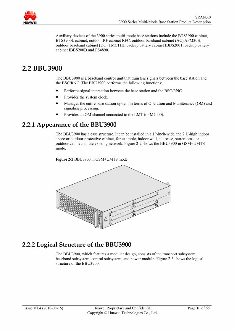
2.2.1 Appearance of the BBU3900 The BBU3900 has a case structure. It can be installed in a 19-inch-wide and 2 U-high indoor space or outdoor protective cabinet, for example, indoor wall, staircase, storerooms, or outdoor cabinets in the existing network. Figure 2-2 shows the BBU3900 in GSM+UMTS mode.
Figure 2-2 BBU3900 in GSM+UMTS mode
2.2.2 Logical Structure of the BBU3900 The BBU3900, which features a modular design, consists of the transport subsystem, baseband subsystem, control subsystem, and power module. Figure 2-3 shows the logical structure of the BBU3900.

SRAN3.0
3900 Series Multi-Mode Base Station Product Description
Issue V1.4 (2010-08-15) Huawei Proprietary and Confidential Copyright © Huawei Technologies Co., Ltd.
Page 11 of 66
Figure 2-3 Logical structure of the BBU3900
Transport subsystem − Provides ports for communication between the base station and the BSC/RNC. − Provides the OM channel for connection to the LMT or M2000.
Baseband subsystem The baseband subsystem processes UL and DL baseband signals. This subsystem consists of the following modules: − UL baseband processing module: consists of the demodulation unit and the decoding
unit. The module processes the UL baseband data before transmitting the data to the RNC through the transport subsystem.
− DL baseband processing module: consists of the modulation unit and the coding unit. The module processes the data from the transport subsystem and then transmits the data to the interface module.
Control subsystem The control subsystem performs centralized management of the entire base station in terms of OM and signaling processing and provides the system clock. − The OM functions involve equipment management, configuration management,
alarm management, software management, and commissioning management. − The signaling processing functions involve NodeB Application Part (NBAP)
signaling processing, Access Link Control Application Part (ALCAP) processing, Stream Control Transmission Protocol (SCTP) processing, and logical resource management.
− The clock module supports the line clock, GPS clock, or free-run clock, generates a synchronization clock for the entire base station, and provides the system clock required by the base station.
Power module − The module converts the -48 V DC or +24 V DC power into the power required by
the boards. − The module collects various types of Boolean alarm information, and reports the
information to the control subsystem.

SRAN3.0
3900 Series Multi-Mode Base Station Product Description
Issue V1.4 (2010-08-15) Huawei Proprietary and Confidential Copyright © Huawei Technologies Co., Ltd.
Page 12 of 66
2.2.3 Boards of the BBU3900 The BBU3900 can be configured with the boards such as the GSM Timing and Main control Unit (GTMU), WCDMA Main Processing Transmission unit (WMPT), WCDMA Baseband Processing unit (WBBP), Universal Transmission Processing unit (UTRP), Universal Power and Environment Interface Unit (UPEU), Universal Environment Interface Unit (UEIU), Satellite Card Clock Unit (USCU), Universal Baseband Radio Interference board (UBRI), and FAN. These boards support plug-and-play, and thus can be configured as required. Figure 2-4 shows the slots of the BBU3900.
Figure 2-4 Slot distribution of the BBU390 boards
Figure 2-5, Figure 2-6, and Figure 2-7 show the typical board configurations of the BBU3900 working in GSM mode, UMTS mode, and GSM+UMTS dual mode respectively.
Figure 2-5 Typical board configuration of the BBU3900 in GSM mode
Figure 2-6 Typical board configuration of the BBU3900 in UMTS mode

SRAN3.0
3900 Series Multi-Mode Base Station Product Description
Issue V1.4 (2010-08-15) Huawei Proprietary and Confidential Copyright © Huawei Technologies Co., Ltd.
Page 13 of 66
Figure 2-7 Typical board configuration of the BBU3900 in GSM+UMTS mode
GTMU The GTMU is the main control and transmission board of the BBU3900 working in GSM mode. It has the following functions: − Provides the CPRI ports for connecting to the RF modules. − Processes clock signals and provides a unified clock for service boards in GSM
mode. − Provides OM management for the GSM network. − Provides four E1s/T1s, one FE electrical port, and one FE optical port.
WMPT The WMPT is the main control and transmission board of the BBU3900 working in UMTS mode. It has the following functions: − Processes clock signals and provides a unified clock for service boards in UMTS
mode. − Provides OM management for the UMTS network. − Provides four E1s/T1s, one FE electrical port, and one FE optical port. − Provides one USB port to download and activate the host software by using a USB
disk. − Processes signaling and manages resources. − In UMTS mode, the WMPT supports the 1 + 1 redundancy mode.
WBBP The WBBP is the baseband processing unit in UMTS mode, and it has the following functions: − Provides CPRI ports for connection to RF modules. − Processes uplink and downlink baseband signals.
UTRP The UTRP is the extension transmission board in UMTS mode, and it has the following functions: − The UTRP2 provides two 100M/1000M Ethernet optical ports, performs functions of
the MAC layer, receives and transmits data on Ethernet links, and analyzes the MAC address.
− The UTRP3 provides eight E1s/T1s and performs inverse multiplexing and demultiplexing on a single ATM cell flow on the eight E1/T1 links.
− The UTRP4 provides eight E1s/T1s, frames and deframes HDLC frames, and allocates and controls the 256 HDLC timeslot channels.
− The UTRP6 supports one unchannelized STM-1/OC-3 interface.

SRAN3.0
3900 Series Multi-Mode Base Station Product Description
Issue V1.4 (2010-08-15) Huawei Proprietary and Confidential Copyright © Huawei Technologies Co., Ltd.
Page 14 of 66
− The UTRP9 provides four 10M/100M/1000M Ethernet electrical ports and performs the functions of the MAC layer and physical layer.
− The UTRP supports the cold backup function. UPEU
The UPEU is the power module of the BBU3900. The UPEU supports the 1 + 1 backup mode and has the following functions: − Converts –48 V DC or +24 V DC power into the working power. − Provides two RS485 monitoring signals. − Provides eight dry contact alarm inputs.
UEIU The UEIU transmits monitoring signals and alarm signals for the BBU3900. The UEIU has the following functions: − Provides two RS485 monitoring signals. − Provides eight dry contact alarm inputs.
USCU The USCU has the following functions: − Provides the synchronization clock information of the base station for the main
control board. − Provides synchronization time information for the lower-level BBU to achieve the
BBU clock cascading. UBRI
The UBRI is the baseband radio interface board of the BBU3900, and it provides 6 CPRI optical ports for GSM mode.
FAN The FAN is the FAN unit of the BBU3900. It provides the BBU3900 with functions such as ventilation and heat dissipation, linear adjustment of the fan speed, and detection of stalled fans.
2.2.4 Ports on the BBU3900 Table 2-1 describes the ports on the mandatory boards of the BBU3900.
Table 2-1 Ports on the mandatory boards of the BBU3900
Board Port Quantity Description
PWR 1 Power supply socket
MON0 1 Providing one RS485 monitoring signal
MON1 1 Providing one RS485 monitoring signal
EXT-ALM0 1 Providing four dry contact alarm inputs
UPEU
EXT-ALM1 1 Providing four dry contact alarm inputs
E1/T1 1 One port supporting four E1s/T1s
USB 1 USB2.0, loading software
WMPT
TST 1 Port for testing the clock

SRAN3.0
3900 Series Multi-Mode Base Station Product Description
Issue V1.4 (2010-08-15) Huawei Proprietary and Confidential Copyright © Huawei Technologies Co., Ltd.
Page 15 of 66
Board Port Quantity Description
FE0 1 FE electrical port for Iub IP transport
FE1 1 FE optical port for Iub IP transport
ETH 1 For local maintenance and commissioning
GPS 1 For GPS clock input
WBBP CPRI 3/6 Port for connection to the RF module, 1.25Gbit/s
CPRI 6 Port for connection to the RF module, 1.25Gbit/s
E1/T1 1 One port supporting four E1s/T1s
USB 1 USB2.0, loading software
TST 1 Port for testing the clock
FE0 1 FE electrical port for Abis IP transport
FE1 1 FE optical port for Abis IP transport
ETH 1 For local maintenance and commissioning
GTMU
EXT 1 Reserved port.
Table 2-2 describes the ports on the optional boards of the BBU3900.
Table 2-2 Ports on the optional boards of the BBU3900
Board Port Quantity Description
E1/T1 2 Supporting eight E1s/T1s
Unchannelized STM-1/OC-3 port
1 Supporting one unchannelized STM-1/OC-3 port
FE/GE0 to FE/GE1
2 FE/GE optical port
UTRP
FE/GE0 to FE/GE3
4 FE/GE electrical port
MON0 1 Providing one RS485 monitoring signal
MON1 1 Providing one RS485 monitoring signal
EXT-ALM0 1 Providing four dry contact alarm inputs
UEIU
EXT-ALM1 1 Providing four dry contact alarm inputs
GPS 1 Receiving the GPS signals USCU
RGPS 2 Receiving the RGPS signals

SRAN3.0
3900 Series Multi-Mode Base Station Product Description
Issue V1.4 (2010-08-15) Huawei Proprietary and Confidential Copyright © Huawei Technologies Co., Ltd.
Page 16 of 66
Board Port Quantity Description
TOD0 1 Receiving or transmitting the 1PPS+TOD signals
TOD1 1 Receiving or transmitting the 1PPS+TOD signals, and receiving TOD signals from the M1000
BITS 1 Receiving the BITS clock signals, supporting adaptive input of 2.048 MHz and 10 MHz clock reference source
M-1PPS port
1 Receiving 1PPS signals from the M1000
UBRI CPRI 6 Port for communication with the RF modules , 1.25 Gbit/s
2.3 RRU3908 The RRU3908 is an outdoor RF remote radio unit, which performs modulation, demodulation, data processing, and combining and dividing for baseband signals and RF signals.
2.3.1 Appearance of the RRU3908 Figure 2-8 shows the RRU3908.
Figure 2-8 RRU3908
2.3.2 Ports on the RRU3908 The RRU3908, which has a modular structure, has its external ports located at the bottom of the module and in the cabling cavity.

SRAN3.0
3900 Series Multi-Mode Base Station Product Description
Issue V1.4 (2010-08-15) Huawei Proprietary and Confidential Copyright © Huawei Technologies Co., Ltd.
Page 17 of 66
Ports on the RRU3908 V1
Table 2-3 Ports on the RRU3908 V1
Port Quantity Description
CPRI_E 1 Eastward optical or electrical port, 1.25Gbit/s
CPRI_W 1 Westward optical or electrical port, 1.25Gbit/s
EXT_ALM 1 Alarm port
ANT_TX/RXA 1 RF TX/RX port A
ANT_TX/RXB 1 RF TX/RX port B
RX_IN/OUT 1 Inter-RRU port
RET 1 Port for the RET antenna communication
Table 2-4 Buttons and terminals on the RRU3908 V1
Label Description
RST Reset button
VSWR -
RTN+
NEG-
Terminals for power cables
Ports on the RRU3908 V2
Table 2-5 Ports on the RRU3908 V2
Port Quantity Description
TX RX CPRI_0 1 Optical/electrical port 0, 1.25Gbit/s or 2.5Gbit/s
TX RX CPRI_1 1 Optical/electrical port 1, 1.25Gbit/s or 2.5Gbit/s
EXT_ALM 1 Alarm port
ANT_TX/RXA 1 RF TX/RX port A
ANT_TX/RXB 1 RF TX/RX port B
RX_IN/OUT 1 Inter-RRU port
RET 1 Port for the RET antenna communication

SRAN3.0
3900 Series Multi-Mode Base Station Product Description
Issue V1.4 (2010-08-15) Huawei Proprietary and Confidential Copyright © Huawei Technologies Co., Ltd.
Page 18 of 66
Table 2-6 Buttons and terminals on the RRU3908 V2
Label Description
RTN(+)0
NEG(-)0
Terminals for power cables
RTN(+)1
NEG(-)1
Cascaded power supply port
2.3.3 Typical Configuration of RRU3908
The GSM power is measured when the modulation scheme is GMSK. If the modulation scheme is 8PSK, the output power is 1.8 dB less than that in GMSK mode.
Only RRU3908 V2 modules support the V2 specifications. The RRU3908 at 1800 MHz supports the LTE mode in terms of hardware. *: The UMTS mode is supported in terms of hardware. When RRU3908 is located in the area at an altitude of 3500 m to 4500 m, the output power back-off
is 1 dB. When RRU3908 is located in the area at an altitude of 4500 m to 6000 m, the output power back-off is 2 dB.
Table 2-7 lists the typical configurations of the RRU3908 V1 at 900MHz/850MHz/1800MHz/1900MHz in compliance with the specifications for multi-carrier base station (Class 2) in 3GPP TS 45.005 V9.0.0.
Table 2-7 Typical configuration of the RRU3908 V1 (900MHz/850MHz/1800MHz/1900MHz, Class 2)
Number of GSM Carriers
Number of UMTS Carriers
Output Power per GSM Carrier (W)
Output Power per UMTS Carrier (W)
1 0 40 0
2 0 40 0
3 0 20 0
4 0 15 0
5 0 12 0
6 0 10 0
1 1 40 30
1 1 30 40
1 2 30 20
2 1 20 30
2 1 15 40
2 2 15 20

SRAN3.0
3900 Series Multi-Mode Base Station Product Description
Issue V1.4 (2010-08-15) Huawei Proprietary and Confidential Copyright © Huawei Technologies Co., Ltd.
Page 19 of 66
Number of GSM Carriers
Number of UMTS Carriers
Output Power per GSM Carrier (W)
Output Power per UMTS Carrier (W)
3 1 10 30
3 2 10 10
4 1 7.5 20
4 2 7.5 10
5 1 6 20
0 1 0 40
0 2 0 30
0 3 0 20
0 4 0 15
Table 2-8 lists the typical configurations of the RRU3908 V1 at 900MHz/1800MHz in compliance with ETSI TS 100 910 V8.20.0.
Table 2-8 Typical configuration of the RRU3908 V1 (900MHz/1800MHz, ETSI)
Number of GSM Carriers
Number of UMTS Carriers
Output Power per GSM Carrier (W)
Output Power per UMTS Carrier (W)
1 0 20 0
2 0 20 0
3 0 15 0
4 0 15 0
5 0 10 0
6 0 10 0
1 1 20 40
2 1 15 30
3 1 10 30
2 2 10 20
1 2 20 20
3 2 10 15
0 1 0 40
0 2 0 30
0 3 0 20

SRAN3.0
3900 Series Multi-Mode Base Station Product Description
Issue V1.4 (2010-08-15) Huawei Proprietary and Confidential Copyright © Huawei Technologies Co., Ltd.
Page 20 of 66
Number of GSM Carriers
Number of UMTS Carriers
Output Power per GSM Carrier (W)
Output Power per UMTS Carrier (W)
0 4 0 15
Table 2-9 lists the typical configurations of the RRU3908 V2 at 900MHz/850MHz in compliance with the specifications for multi-carrier base station (Class 2) in 3GPP TS 45.005 V9.0.0.
Table 2-9 Typical configurations of the RRU3908 V2 (900MHz/850MHz, Class 2)
Number of GSM Carriers
Number of UMTS Carriers
Output Power per GSM Carrier (W)
Output Power per UMTS Carrier (W)
1 0 40 0
2 0 40 0
3 0 20 0
4 0 20 0
5 0 13 0
6 0 13 0
7 0 10 0
8 0 10 0
1 1 40 40
2 1 20 40
2 1 30 20
3 1 13 40
4 1 10 40
1 2 40 20
2 2 20 20
3 2 13 20
4 2 10 20
0 1 0 60
0 1 0 2 x 40 (MIMO)
0 2 0 40
0 2 0 2 x 20 (MIMO)
0 3 0 20
0 3 0 2 x 10 (MIMO)
0 4 0 20

SRAN3.0
3900 Series Multi-Mode Base Station Product Description
Issue V1.4 (2010-08-15) Huawei Proprietary and Confidential Copyright © Huawei Technologies Co., Ltd.
Page 21 of 66
Number of GSM Carriers
Number of UMTS Carriers
Output Power per GSM Carrier (W)
Output Power per UMTS Carrier (W)
0 4 0 2 x 10 (MIMO)
Table 2-10 lists the typical configurations of the RRU3908 V2 at 900MHz in compliance with ETSI TS 100 910 V8.20.0.
Table 2-10 Typical configurations of the RRU3908 V2 (900MHz, ETSI)
Number of GSM Carriers
Number of UMTS Carriers
Output Power per GSM Carrier (W)
Output Power per UMTS Carrier (W)
1 0 30 0
2 0 30 0
3 0 20 0
4 0 20 0
5 0 13 0
6 0 13 0
7 0 10 0
8 0 10 0
1 1 30 40
2 1 20 40
2 1 30 20
3 1 13 40
4 1 10 30
1 2 20 20
2 2 20 20
3 2 13 20
4 2 10 20
0 1 0 60
0 1 0 2 x 40 (MIMO)
0 2 0 40
0 2 0 2 x 20 (MIMO)
0 3 0 20
0 3 0 2 x 10 (MIMO)

SRAN3.0
3900 Series Multi-Mode Base Station Product Description
Issue V1.4 (2010-08-15) Huawei Proprietary and Confidential Copyright © Huawei Technologies Co., Ltd.
Page 22 of 66
Number of GSM Carriers
Number of UMTS Carriers
Output Power per GSM Carrier (W)
Output Power per UMTS Carrier (W)
0 4 0 20
0 4 0 2 x 10 (MIMO)
2.4 MRFU 2.4.1 Appearance of the MRFU
The MRFU can be installed in an indoor cabinet or a protective outdoor cabinet. Figure 2-9 shows the MRFU.
Figure 2-9 MRFU
2.4.2 Ports on the MRFU The MRFU features a modular structure. Table 2-11 describes the ports on the MRFU.
Table 2-11 Ports on the MRFU
Port Quantity Description
PWR 1 Power supply socket
ANT_RXB 1
ANT_TX/RXA 1
Antenna port for connection to the antenna system

SRAN3.0
3900 Series Multi-Mode Base Station Product Description
Issue V1.4 (2010-08-15) Huawei Proprietary and Confidential Copyright © Huawei Technologies Co., Ltd.
Page 23 of 66
Port Quantity Description
CPRI0 1 Connected to the BBU or to the upper-level cascaded MRFU, 1.25Gbit/s
CPRI1 1 Connected to the BBU or to the lower-level cascaded MRFU, 1.25Gbit/s
RX_INB 1 Input port for diversity RX
RX_OUTA 1 Output port for main RX
MON 1 Port for monitoring and maintenance
2.4.3 Typical Configuration of MRFU
Only MRFU V2 modules support the V2 specifications. The MRFU at 1800 MHz supports the LTE mode in terms of hardware. *: The UMTS mode is supported in terms of hardware. The GSM power is measured when the modulation scheme is GMSK. If the modulation scheme is
8PSK, the output power is 1.8 dB less than that in GMSK mode. When MRFU is located in the area at an altitude of 3500 m to 4500 m, the output power back-off is
1 dB. When MRFU is located in the area at an altitude of 4500 m to 6000 m, the output power back-off is 2 dB.
Table 2-12 lists the typical configurations of the MRFU V2 at 900MHz/1800MHz in compliance with the specifications for multi-carrier base station (Class 2) in 3GPP TS 45.005 V9.0.0.
Table 2-12 Typical configurations of the MRFU V2 (900MHz/1800MHz, Class 2)
Number of GSM Carriers
Number of UMTS Carriers
Output Power per GSM Carrier (W)
Output Power per UMTS Carrier (W)
1 0 60 0
2 0 40 0
3 0 27 0
4 0 20 0
5 0 16 0
6 0 12 0
0 1 0 60
0 1 0 2 x 60 (MIMO with two MRFUs)
0 2 0 40

SRAN3.0
3900 Series Multi-Mode Base Station Product Description
Issue V1.4 (2010-08-15) Huawei Proprietary and Confidential Copyright © Huawei Technologies Co., Ltd.
Page 24 of 66
Number of GSM Carriers
Number of UMTS Carriers
Output Power per GSM Carrier (W)
Output Power per UMTS Carrier (W)
0 2 0 2 x 40 (MIMO with two MRFUs)
0 3 0 27
0 3 0 2 x 27 (MIMO with two MRFUs)
0 4 0 20
0 4 0 2 x 20 (MIMO with two MRFUs)
Table 2-13 lists the typical configurations of the MRFU V2 at 900MHz/1800MHz in compliance with ETSI TS 100 910 V8.20.0.
Table 2-13 Typical configurations of the MRFU V2 (900MHz/1800MHz, ETSI)
Number of GSM Carriers
Number of UMTS Carriers
Output Power per GSM Carrier (W)
Output Power per UMTS Carrier (W)
1 0 40 0
2 0 40 0
3 0 27 0
4 0 20 0
5 0 12 0
6 0 10 0
0 1 0 60
0 1 0 2 x 60 (MIMO with 2 MRFUs)
0 2 0 40
0 2 0 2 x 40 (MIMO with two MRFUs)
0 3 0 27
0 3 0 2 x 27 (MIMO with two MRFUs)
0 4 0 20
0 4 0 2 x 20 (MIMO with two MRFUs)

SRAN3.0
3900 Series Multi-Mode Base Station Product Description
Issue V1.4 (2010-08-15) Huawei Proprietary and Confidential Copyright © Huawei Technologies Co., Ltd.
Page 25 of 66
Table 2-14 lists the typical configurations of the MRFU V1 at 1900MHz in compliance with the specifications for multi-carrier base station (Class 2) in 3GPP TS 45.005 V9.0.0.
Table 2-14 Typical configurations of the MRFU V1 (1900MHz, Class 2)
Number of GSM Carriers
Number of UMTS Carriers
Output Power per GSM Carrier (W)
Output Power per UMTS Carrier (W)
1 0 60 0
2 0 40 0
3 0 27 0
4 0 20 0
5 0 12 0
6 0 10 0
0 1 0 60
0 2 0 40
0 3 0 27
0 4 0 20
2.5 Power Sharing When the BTS downlink power control is enabled, the total output power of carriers in a cell is always equal to or less than “Maximum Output Power of Carrier × Number of Carriers”. Based on the estimated power that calls need, if the calls with different power are grouped into different timeslots according to a certain rule, the probability that the total output power of carriers in the cell is less than “Maximum Output Power of Carrier × Number of Carriers” is further increased. Or even, the total output power of carriers in the cell is far less than “Maximum Output Power of Carrier × Number of Carriers”. Hence, each carrier can carry more power than standard configuration.

SRAN3.0
3900 Series Multi-Mode Base Station Product Description
Issue V1.4 (2010-08-15) Huawei Proprietary and Confidential Copyright © Huawei Technologies Co., Ltd.
Page 26 of 66
The GSM power is measured when the modulation scheme is GMSK. If the modulation scheme is
8PSK, the output power is 1.8 dB less than that in GMSK mode. Only RRU3908 V2 modules support the V2 specifications. Only MRFU V2 modules support the V2 specifications. The RRU3908 at 1800 MHz supports the LTE mode in terms of hardware. The MRFU at 1800 MHz supports the LTE mode in terms of hardware. *: The UMTS mode is supported in terms of hardware. When RRU3908 is located in the area at an altitude of 3500 m to 4500 m, the output power back-off
is 1 dB. When RRU3908 is located in the area at an altitude of 4500 m to 6000 m, the output power back-off is 2 dB.
When MRFU is located in the area at an altitude of 3500 m to 4500 m, the output power back-off is 1 dB. When MRFU is located in the area at an altitude of 4500 m to 6000 m, the output power back-off is 2 dB.
Factors such as the site-to-site distance, frequency-reuse factor, power control algorithm, and traffic model affect the gain achieved by dynamic power allocation. Therefore, in most cases, the network planning can be based on the power specification achieved by dynamic power allocation.
In power sharing mode, the power control and DTX should be set to ON. Output power with power sharing assumes a random distribution of UEs in the cell.
Table 2-15 lists the typical configurations of the RRU3908 V1 at 900MHz/850MHz/1800MHz/1900MHz in compliance with the specifications for multi-carrier base station (Class 2) in 3GPP TS 45.005 V9.0.0.
Table 2-15 Typical configuration of the RRU3908 V1 (900MHz/850MHz/1800MHz/1900MHz, Class2)
Number of GSM Carriers
Number of UMTS Carriers
Output Power per GSM Carrier (W)
Output Power per UMTS Carrier (W)
1 0 40 0
2 0 40 0
3 0 20 0
4 0 20 0
5 0 12 0
6 0 12 0
1 1 40 30
1 1 30 40
1 2 30 20
2 1 15 40
2 1 20 30
2 2 15 20
3 1 12 30
3 2 12 10

SRAN3.0
3900 Series Multi-Mode Base Station Product Description
Issue V1.4 (2010-08-15) Huawei Proprietary and Confidential Copyright © Huawei Technologies Co., Ltd.
Page 27 of 66
Number of GSM Carriers
Number of UMTS Carriers
Output Power per GSM Carrier (W)
Output Power per UMTS Carrier (W)
4 1 10 20
4 2 10 10
5 1 9 20
0 1 0 40
0 2 0 30
0 3 0 20
0 4 0 15
Table 2-16 lists the typical configurations of the RRU3908 V1 at 900MHz/1800MHz in compliance with ETSI TS 100 910 V8.20.0.
Table 2-16 Typical configuration of the RRU3908 V1 (900MHz/1800MHz, ETSI)
Number of GSM Carriers
Number of UMTS Carriers
Output Power per GSM Carrier (W)
Output Power per UMTS Carrier (W)
1 0 20 0
2 0 20 0
3 0 15 0
4 0 15 0
5 0 12 0
6 0 12 0
1 1 20 40
2 1 15 30
3 1 12 30
1 2 20 20
2 2 10 20
3 2 12 15
0 1 0 40
0 2 0 30
0 3 0 20
0 4 0 15

SRAN3.0
3900 Series Multi-Mode Base Station Product Description
Issue V1.4 (2010-08-15) Huawei Proprietary and Confidential Copyright © Huawei Technologies Co., Ltd.
Page 28 of 66
Table 2-17 lists the typical configurations of the RRU3908 V2 at 900MHz/850MHz in compliance with the specifications for multi-carrier base station (Class 2) in 3GPP TS 45.005 V9.0.0.
Table 2-17 Typical configurations of the RRU3908 V2 (900MHz/850MHz, Class 2)
Number of GSM Carriers
Number of UMTS Carriers
Output Power per GSM Carrier (W)
Output Power per UMTS Carrier (W)
1 0 40 0
2 0 40 0
3 0 20 0
4 0 20 0
5 0 15 0
6 0 15 0
7 0 13 0
8 0 13 0
1 1 40 40
2 1 20 40
2 1 30 20
3 1 15 40
4 1 13 40
1 2 40 20
2 2 20 20
3 2 15 20
4 2 13 20
0 1 0 60
0 1 0 2 x 40 (MIMO)
0 2 0 40
0 2 0 2 x 20 (MIMO)
0 3 0 20
0 3 0 2 x 10 (MIMO)
0 4 0 20
0 4 0 2 x 10 (MIMO)
SRAN3.0
3900 Series Multi-Mode Base Station Product Description
Issue V1.4 (2010-08-15) Huawei Proprietary and Confidential Copyright © Huawei Technologies Co., Ltd.
Page 29 of 66
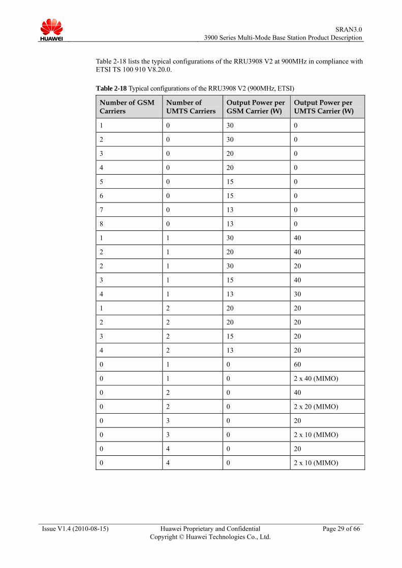
Table 2-18 lists the typical configurations of the RRU3908 V2 at 900MHz in compliance with ETSI TS 100 910 V8.20.0.
Table 2-18 Typical configurations of the RRU3908 V2 (900MHz, ETSI)
Number of GSM Carriers
Number of UMTS Carriers
Output Power per GSM Carrier (W)
Output Power per UMTS Carrier (W)
1 0 30 0
2 0 30 0
3 0 20 0
4 0 20 0
5 0 15 0
6 0 15 0
7 0 13 0
8 0 13 0
1 1 30 40
2 1 20 40
2 1 30 20
3 1 15 40
4 1 13 30
1 2 20 20
2 2 20 20
3 2 15 20
4 2 13 20
0 1 0 60
0 1 0 2 x 40 (MIMO)
0 2 0 40
0 2 0 2 x 20 (MIMO)
0 3 0 20
0 3 0 2 x 10 (MIMO)
0 4 0 20
0 4 0 2 x 10 (MIMO)

SRAN3.0
3900 Series Multi-Mode Base Station Product Description
Issue V1.4 (2010-08-15) Huawei Proprietary and Confidential Copyright © Huawei Technologies Co., Ltd.
Page 30 of 66
Table 2-19 lists the typical configurations of the MRFU V2 at 900MHz/1800MHz in compliance with the specifications for multi-carrier base station (Class 2) in 3GPP TS 45.005 V9.0.0.
Table 2-19 Typical configurations of the MRFU V2 (900MHz/1800MHz, Class 2)
Number of GSM Carriers
Number of UMTS Carriers
Number of LTE Carriers
Output Power per GSM Carrier (W)
Output Power per UMTS Carrier (W)
Output Power per LTE Carrier (W)
1 0 0 60 0 0
2 0 0 40 0 0
3 0 0 31 0 0
4 0 0 27 0 0
5 0 0 20 0 0
6 0 0 20 0 0
0 1 0 0 60 0
0 1 0 0 2 x 60 (MIMO with two MRFUs)
0
0 2 0 0 40 0
0 2 0 0 2 x 40 (MIMO with two MRFUs)
0
0 3 0 0 27 0
0 3 0 0 2 x 27 (MIMO with two MRFUs)
0
0 4 0 0 20 0
0 4 0 0 2 x 20 (MIMO with two MRFUs)
0
0 0 1 0 0 1 x 60
Table 2-20 lists the typical configurations of the MRFU V2 at 900MHz/1800MHz in compliance with ETSI TS 100 910 V8.20.0.

SRAN3.0
3900 Series Multi-Mode Base Station Product Description
Issue V1.4 (2010-08-15) Huawei Proprietary and Confidential Copyright © Huawei Technologies Co., Ltd.
Page 31 of 66
Table 2-20 Typical configurations of the MRFU V2 (900MHz/1800MHz, ETSI)
Number of GSM Carriers
Number of UMTS Carriers
Number of LTE Carriers
Output Power per GSM Carrier (W)
Output Power per UMTS Carrier (W)
Output Power per LTE Carrier (W)
1 0 0 40 0 0
2 0 0 40 0 0
3 0 0 31 0 0
4 0 0 27 0 0
5 0 0 16 0 0
6 0 0 16 0 0
0 1 0 0 60 0
0 1 0 0 2 x 60 (MIMO with two MRFUs)
0
0 2 0 0 40 0
0 2 0 0 2 x 40 (MIMO with two MRFUs)
0
0 3 0 0 27 0
0 3 0 0 2 x 27 (MIMO with two MRFUs)
0
0 4 0 0 20 0
0 4 0 0 2 x 20 (MIMO with two MRFUs)
0
0 0 1 0 0 1 x 60
Table 2-21 lists the typical configurations of the MRFU V1 at 1900MHz in compliance with the specifications for multi-carrier base station (Class 2) in 3GPP TS 45.005 V9.0.0.
Table 2-21 Typical configurations of the MRFU V1 (1900MHz, Class 2)
Number of GSM Carriers
Number of UMTS Carriers
Output Power per GSM Carrier (W)
Output Power per UMTS Carrier (W)
1 0 60 0
2 0 40 0
SRAN3.0
3900 Series Multi-Mode Base Station Product Description
Issue V1.4 (2010-08-15) Huawei Proprietary and Confidential Copyright © Huawei Technologies Co., Ltd.
Page 32 of 66
Number of GSM Carriers
Number of UMTS Carriers
Output Power per GSM Carrier (W)
Output Power per UMTS Carrier (W)
3 0 31 0
4 0 27 0
5 0 20 0
6 0 16 0
0 1 0 60
0 2 0 40
0 3 0 27
0 4 0 20
2.6 Auxiliary Devices 2.6.1 BTS3900 Cabinet
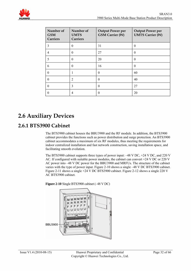
The BTS3900 cabinet houses the BBU3900 and the RF module. In addition, the BTS3900 cabinet provides the functions such as power distribution and surge protection. An BTS3900 cabinet accommodates a maximum of six RF modules, thus meeting the requirements for indoor centralized installation and fast network construction, saving installation space, and facilitating smooth evolution.
The BTS3900 cabinet supports three types of power input: –48 V DC, +24 V DC, and 220 V AC. If configured with suitable power modules, the cabinet can convert +24 V DC or 220 V AC power into –48 V DC power for the BBU3900 and MRFUs. The structure of the cabinet varies with the type of power input. Figure 2-10 shows a single –48 V DC BTS3900 cabinet. Figure 2-11 shows a single +24 V DC BTS3900 cabinet. Figure 2-12 shows a single 220 V AC BTS3900 cabinet.
Figure 2-10 Single BTS3900 cabinet (–48 V DC)

SRAN3.0
3900 Series Multi-Mode Base Station Product Description
Issue V1.4 (2010-08-15) Huawei Proprietary and Confidential Copyright © Huawei Technologies Co., Ltd.
Page 33 of 66
Figure 2-11 Single BTS3900 cabinet (+24 V DC)
Figure 2-12 Single BTS3900 cabinet (220 V AC)
The power supply unit (PSU) converts the +24 V DC into the –48 V DC that is led into the direct current
distribution unit. The Power and Environment Monitoring Unit (PMU) provides a comprehensive function of power supply
management, power distribution check, and alarm reporting.
2.6.2 BTS3900L Cabinet The BTS3900L cabinet houses the BBU3900 and RF modules. In addition, the BTS3900L cabinet provides the functions such as power distribution and surge protection. A single BTS3900L can be installed with a maximum of 12 RF modules and two BBU3900s. This improves the integration of indoor site solutions, saves installation space, and facilitates smooth evolution.
The BTS3900L supports the –48 V DC power input. Figure 2-13 shows the internal structure of the BTS3900L.

SRAN3.0
3900 Series Multi-Mode Base Station Product Description
Issue V1.4 (2010-08-15) Huawei Proprietary and Confidential Copyright © Huawei Technologies Co., Ltd.
Page 34 of 66
Figure 2-13 Internal structure of the BTS3900L
2.6.3 RFC The RFC, which is used outdoors, adopts a direct-ventilation mode for heat dissipation. The APM30H or TMC11H is stacked on the RFC. Then, the RFC provides power supply, surge protection, and other protections for the BBU3900 and MRFUs. The RFC can accommodate a maximum of six RF modules. Figure 2-14 shows the internal structure of the RFC.

SRAN3.0
3900 Series Multi-Mode Base Station Product Description
Issue V1.4 (2010-08-15) Huawei Proprietary and Confidential Copyright © Huawei Technologies Co., Ltd.
Page 35 of 66
Figure 2-14 Internal structure of the RFC
2.6.4 APM30H The APM30H, an advanced power module, is an outdoor baseband cabinet (AC). It provides distributed base stations and outdoor macro base stations with –48 V DC power. It also provides space for the installation of the BBU3900 and customer equipment. If the heater is not installed, the APM30H provides 7 U space for user equipment. If the heater is installed, the APM30H provides 6 U space for user equipment. The APM30H is light and small. It dissipates heat through the heat exchanger and inner and outer air circulation fans. Figure 2-15 shows the internal structure of the APM30H.
Figure 2-15 Internal structure of the APM30H
(1) Heat exchanger core (2) Fan (3) Central Monitoring Unit type A (CMUA) (4) Hert Power Monitoring Interface unit (HPMI) (5) PSU (AC/DC) (6) EPS

SRAN3.0
3900 Series Multi-Mode Base Station Product Description
Issue V1.4 (2010-08-15) Huawei Proprietary and Confidential Copyright © Huawei Technologies Co., Ltd.
Page 36 of 66
2.6.5 TMC11H The TMC11H, a baseband cabinet (DC), is used outdoors. It is small, easy to move, and dissipates heats through the heat exchanger and inner and outer air circulation fans. When more space is required for transmission devices, the TMC11H can be configured. The TMC11H provides a space of 11 U for customer equipment, and the BBU3900 can be installed in the TMC11H. Figure 2-16 shows the internal structure of the TMC11H.
Figure 2-16 Internal structure of the TMC11H
(1) HPMI (2) Fan (inner circulation) (3) CMUA (4) DCDU-03 (5) Fan (outer circulation) (6) Heat changer core
2.6.6 IBBS200T When long-time power backup is required, the battery cabinet IBBS200T can be configured. The IBBS200T is used outdoors. It is small, easy to move, and dissipates heat through the TEC.
Configured with built-in battery groups, an IBBS200T can provide a maximum of -48 V 184 Ah backup power. Figure 2-17 shows the internal structure of the IBBS200T.
Figure 2-17 Internal structure of the IBBS200T

SRAN3.0
3900 Series Multi-Mode Base Station Product Description
Issue V1.4 (2010-08-15) Huawei Proprietary and Confidential Copyright © Huawei Technologies Co., Ltd.
Page 37 of 66
2.6.7 IBBS200D The IBBS200D is optional. It can be configured with a maximum of –48 V 184 Ah built-in battery group to supply backup power to the equipment for a long time in certain situations. The IBBS200D can dissipate heat in direct-ventilation mode.
Figure 2-18 shows the internal structure of the IBBS200D.
Figure 2-18 Internal structure of the IBBS200D
2.6.8 PS4890 The PS4890, an indoor power cabinet, provides DC power and power backup for the DBS3900 or BTS3900. The PS4890 can also provide installation space for the indoor BBU and transmission equipment.
The PS4890 features compact design and light weight. It can be installed on the ground. Batteries (48V 92Ah or 48V 184Ah) can be configured in the PS4890.
Figure 2-19 shows the internal structure of the PS4890.

SRAN3.0
3900 Series Multi-Mode Base Station Product Description
Issue V1.4 (2010-08-15) Huawei Proprietary and Confidential Copyright © Huawei Technologies Co., Ltd.
Page 38 of 66
Figure 2-19 Internal structure of the PS4890
(1) Power system (AC/DC) (2) DCDU-04 (3) DCDU-03 (4) Wiring copper bar for the negative poles of the batteries (5) Support plate for the batteries (6) Wiring copper bar for the positive poles of the batteries

SRAN3.0
3900 Series Multi-Mode Base Station Product Description
Issue V1.4 (2010-08-15) Huawei Proprietary and Confidential Copyright © Huawei Technologies Co., Ltd.
Page 39 of 66
3 Products and Application Scenarios
3.1 Overview Flexible combinations of the basic components and auxiliary devices can provide comprehensive solutions that are applicable to specific scenarios of operators, such as indoor centralized installation, outdoor centralized installation, outdoor distributed installation, or co-siting of base stations in different modes.
Diverse combinations of the basic modules and auxiliary devices form the following products that are applied to different scenarios, thus meeting requirements for fast and cost-effective network deployment:
Macro base station in one or more cabinets − Indoor model: BTS3900, BTS3900L − Outdoor model: BTS3900A The cabinet macro base station is installed with the BBU3900 and MRFUs in centralized mode. The cabinet macro base station is applicable to a centralized installation scenario. The BTS3900 and BTS3900L are used for the indoor centralized installation scenario, and the BTS3900A is used for the outdoor centralized installation scenario.
Distributed base station The distributed base station, that is, the DBS3900, consists of the BBU3900 and the RRU3908. In a distributed installation scenario, the RRU3908 can be installed close to the antenna so as to reduce feeder loss and improve the performance of the base station.
3.2 Application Scenarios 3.2.1 Application Scenarios of the DBS3900
As environmental concern and lease cost increases, site acquisition for base stations has become a bottleneck during network construction, rendering it increasingly difficult to construct new sites. The DBS3900 developed by Huawei features high integration, easy installation, and low environment requirements. All these features can facilitate site acquisition and 2G/3G co-siting.

SRAN3.0
3900 Series Multi-Mode Base Station Product Description
Issue V1.4 (2010-08-15) Huawei Proprietary and Confidential Copyright © Huawei Technologies Co., Ltd.
Page 40 of 66
With these features, the DBS3900 fully addresses operators' concern over site acquisition, facilitates network planning and optimization, and reduces network construction time. Thus, the DBS3900 enables operators to efficiently deploy a high-performance GSM/UMTS/LTE network with a low Total Cost of Ownership (TCO) by minimizing the investment in electricity, space, and manpower.
Typical Installation Scenarios of the DBS3900 The BBU3900 can be installed in a 19inch-wide and 2 U-high confined space, such as on a wall, on the staircase, in the storeroom, or in an outdoor cabinet on the existing network. The RRU3908 has a wide variety of installation options, such as installation on a pole, wall, or stand.
Figure 3-1 shows the typical installation scenarios of the DBS3900.
Figure 3-1 Typical installation scenarios of the DBS3900
Typical Application Scenarios of the DBS3900 Because of features such as flexible installation, natural heat dissipation, mute working mode, and fast network construction, the DBS3900 is applicable to various scenarios. The scenarios include the urban coverage, rural coverage, coverage inside buildings, and coverage along the highways and railways. Figure 3-2 shows the typical application scenarios of the DBS3900.

SRAN3.0
3900 Series Multi-Mode Base Station Product Description
Issue V1.4 (2010-08-15) Huawei Proprietary and Confidential Copyright © Huawei Technologies Co., Ltd.
Page 41 of 66
Figure 3-2 Typical application scenarios of the DBS3900
3.2.2 Application Scenarios of the BTS3900
Typical Installation Scenarios of the BTS3900 The BTS3900, as one of the most compact indoor macro base stations in the industry, features large and scalable capacity. It has a small footprint and supports the GSM+UMTS dual-mode application. Figure 3-3 shows the typical installation scenarios of the BTS3900.
Figure 3-3 Typical installation scenarios of the BTS3900

SRAN3.0
3900 Series Multi-Mode Base Station Product Description
Issue V1.4 (2010-08-15) Huawei Proprietary and Confidential Copyright © Huawei Technologies Co., Ltd.
Page 42 of 66
Typical Application Scenarios of the BTS3900 The BTS3900, the indoor macro base station, is applicable to the indoor centralized installation scenario. Figure 3-4 shows the typical application scenarios of the BTS3900.
Figure 3-4 Typical application scenarios of the BTS3900
3.2.3 Application Scenarios of the BTS3900A
Typical Installation Scenarios of the BTS3900A The BTS3900A, the outdoor macro base station, is applicable to the outdoor centralized installation scenario. The RFU is installed in the RFC, and the BBU3900 is installed in the APM30H or TMC11H. Figure 3-5, Figure 3-6, Figure 3-7, and Figure 3-8 show the following combinations of the products:
APM30H+RFC TMC11H+RFC APM30H+RFC+IBBS200T APM30H+RFC+TMC11H+IBBS200T

SRAN3.0
3900 Series Multi-Mode Base Station Product Description
Issue V1.4 (2010-08-15) Huawei Proprietary and Confidential Copyright © Huawei Technologies Co., Ltd.
Page 43 of 66
Figure 3-5 APM30H + RFC
Figure 3-6 TMC11H + RFC

SRAN3.0
3900 Series Multi-Mode Base Station Product Description
Issue V1.4 (2010-08-15) Huawei Proprietary and Confidential Copyright © Huawei Technologies Co., Ltd.
Page 44 of 66
Figure 3-7 APM30H + RFC + IBBS200T
Figure 3-8 APM30H + RFC + TMC11H + IBBS200T
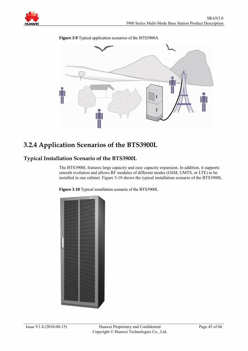
Typical Application Scenarios of the BTS3900A The BTS3900A, the outdoor macro base station, is applicable to the outdoor centralized installation scenario. Figure 3-9 shows the typical application scenarios of the BTS3900A.
SRAN3.0
3900 Series Multi-Mode Base Station Product Description
Issue V1.4 (2010-08-15) Huawei Proprietary and Confidential Copyright © Huawei Technologies Co., Ltd.
Page 45 of 66
Figure 3-9 Typical application scenarios of the BTS3900A
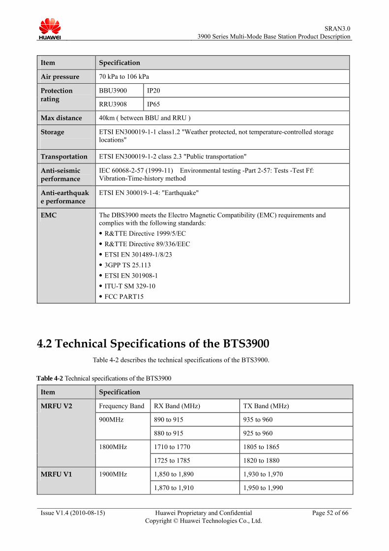
3.2.4 Application Scenarios of the BTS3900L
Typical Installation Scenario of the BTS3900L The BTS3900L features large capacity and easy capacity expansion. In addition, it supports smooth evolution and allows RF modules of different modes (GSM, UMTS, or LTE) to be installed in one cabinet. Figure 3-10 shows the typical installation scenario of the BTS3900L.
Figure 3-10 Typical installation scenario of the BTS3900L

SRAN3.0
3900 Series Multi-Mode Base Station Product Description
Issue V1.4 (2010-08-15) Huawei Proprietary and Confidential Copyright © Huawei Technologies Co., Ltd.
Page 46 of 66
Typical Application Scenario of the BTS3900L The BTS3900L, an indoor macro base station, can be used in indoor centralized scenarios. Figure 3-11 shows the typical application scenario of the BTS3900L.
Figure 3-11 Typical application scenario of the BTS3900L

SRAN3.0
3900 Series Multi-Mode Base Station Product Description
Issue V1.4 (2010-08-15) Huawei Proprietary and Confidential Copyright © Huawei Technologies Co., Ltd.
Page 47 of 66
4 Technical Specification
4.1 Technical Specifications of the DBS3900 Table 4-1describes the technical specifications of the DBS3900.
Table 4-1 Technical specifications of the DBS3900
Item Specification
Frequency Band
RX Band (MHz) TX Band (MHz)
890 to 915 935 to 960 900 MHz
880~905 925~950
850 MHz 824 to 849 869 to 894
1,710 to 1,755 1,805 to 1,850 1800 MHz
1,740 to 1,785 1,835 to 1,880
1,850 to 1,890 1,930 to 1,970
RRU3908 V1
1900 MHz
1,870 to 1,910 1,950 to 1,990
890 to 915 935 to 960 900 MHz
880 to 915 925 to 960
RRU3908 V2
850 MHz 824 to 849 869 to 894

SRAN3.0
3900 Series Multi-Mode Base Station Product Description
Issue V1.4 (2010-08-15) Huawei Proprietary and Confidential Copyright © Huawei Technologies Co., Ltd.
Page 48 of 66
Item Specification
GSM BBU3900: S24/24/24 RRU3908 (V1): Each RRU3908 supports six TRXs. RRU3908 (V2, ETSI): Each RRU3908 supports six TRXs. RRU3908 (V2, Class 2): Each RRU3908 supports eight TRXs Each sector supports a maximum of 24 carriers.
UMTS BBU3900: S8/8/8 (1,536 CEs in the UL and 1,536 CEs + 15 × 24 HSDPA codes in the DL) RRU3908: Each RRU3908 supports four TRXs Each sector supports a maximum of eight carriers.
Capacity
GSM+UMTS BBU3900: GSM S24/24/24+UMTS S8/8/8 (1,536 CEs in the UL and 1,536 CEs + 15 × 24 HSDPA codes in the DL) RRU3908 (V1): G5U1or G4U2 RRU3908 (V2, ETSI): G3U2 RRU3908 (V2, Class 2): G4U2
–125.5 dBm As recommended in 3GPP TS25.104, the receiver sensitivity (full band) is measured at the antenna connector on condition that the channel rate reaches 12.2 kbit/s and the BER does not exceed 0.001. Frequency band (MHz): 890 to 915, 935 to 960,1800 MHz
–126.2 dBm The receiver sensitivity is measured on the center frequency at the antenna connector on condition that 12.2 kbit/s Adaptive Multi Rate (AMR) service is in progress and the BER does not exceed 0.001. Frequency band (MHz): 890 to 915, 935 to 960,1800 MHz
–125.3 dBm As recommended in 3GPP TS25.104, the receiver sensitivity (full band) is measured at the antenna connector on condition that the channel rate reaches 12.2 kbit/s and the BER does not exceed 0.001. Frequency band (MHz): 880 to 915, 925 to 960
UMTS
–126.0 dBm The receiver sensitivity is measured on the center frequency at the antenna connector on condition that 12.2 kbit/s Adaptive Multi Rate (AMR) service is in progress and the BER does not exceed 0.001. Frequency band (MHz): 880 to 915, 925 to 960
–113.5 dBm Frequency band (MHz): 890 to 915, 935 to 960
–113.3dBm Frequency band (MHz): 880 to 915, 925 to 960
Receiver sensitivity
GSM
–113.8 dBm 1800 MHz

SRAN3.0
3900 Series Multi-Mode Base Station Product Description
Issue V1.4 (2010-08-15) Huawei Proprietary and Confidential Copyright © Huawei Technologies Co., Ltd.
Page 49 of 66
Item Specification
GSM GTMU 4 E1s/T1s, 1 FE electrical port, 1 FE optical port
WMPT 4 E1s/T1s, 1 FE electrical port, 1 FE optical port
GTMU 4 E1s/T1s, 1 FE electrical port, 1 FE optical port
UTRP2 2 FE/GE optical ports
UTRP3 8 E1s/T1s
UTRP4 8 E1s/T1s
UTRP6 1 STM-1/OC-3 port
GSM+UMTS
UTRP9 4 FE/GE electrical ports
WMPT 4 E1s/T1s, 1 FE electrical port, 1 FE optical port
UTRP2 2 FE/GE optical ports
UTRP3 8 E1s/T1s
UTRP4 8 E1s/T1s
UTRP6 1 STM-1/OC-3 port
Transmission port
UMTS
UTRP9 4 FE/GE electrical ports
Clock synchronization
Line clock, GPS clock, BITS clock, clock of the Oven Controlled Crystal Oscillator (OCXO) in free-run mode, and IP clock
Dimension (H x W x D )
BBU3900: 86 mm × 442 mm × 310 mm RRU3908: 485 mm × 380 mm × 170 mm (with the housing) RRU3908: 480 mm × 356 mm × 140 mm (without the housing)
Weight BBU3900 ≤ 12 kg (in full configuration) BBU3900 ≤ 7 kg (in typical configuration) RRU3908: 21 kg (without the housing) RRU3908: 23 kg (with the housing)
Input power BBU3900: –48 V DC; voltage range: –38.4 V DC to –57 V DC RRU3908: –48 V DC; voltage range: –36 V DC to –57 V DC

SRAN3.0
3900 Series Multi-Mode Base Station Product Description
Issue V1.4 (2010-08-15) Huawei Proprietary and Confidential Copyright © Huawei Technologies Co., Ltd.
Page 50 of 66
Item Specification
RRU3908 V1,900MHz,Class2
Configuration Output Power per Carrier (W)
Typical Power Consumption (W)
Maximum Power Consumption (W)
3 × 2 20 760 910
3 × 4 20 730 1,070
GSM
3 × 6 12 730 1,070
GSM 3 × 2 + UMTS 3 × 1
20/20 870 1,090
GSM 3 × 4 + UMTS 3 × 1
10/20 820 1,050
GSM+UMTS
GSM 3 × 4 + UMTS 3 × 2
10/10 820 1,050
3 × 1 20 490 590
3 × 2 20 640 790
3 × 3 20 880 1,100
UMTS
3 × 4 15 880 1,110
RRU3908 V1,900MHz,ETSI
Configuration Output Power per Carrier (W)
Typical Power Consumption (W)
Maximum Power Consumption (W)
3 × 2 20 650 840
3 × 4 10 790 980
GSM
3 × 6 10 1,000 1,350
GSM 3 × 1 + UMTS 3 × 1
20/20 770 890
GSM 3 × 2 + UMTS 3 × 1
10/20 810 990
GSM+UMTS
GSM 3 × 3 + UMTS 3 × 1
10/20 890 1,130
RRU3908 V2,900MHz/850MHz,Class2
Configuration Output Power per Carrier (W)
Typical Power Consumption (W)
Maximum Power Consumption (W)
3 x 2 20 540 710
3 x 4 20 700 1,130
Power consumption
GSM
3 x 6 13 660 1,130

SRAN3.0
3900 Series Multi-Mode Base Station Product Description
Issue V1.4 (2010-08-15) Huawei Proprietary and Confidential Copyright © Huawei Technologies Co., Ltd.
Page 51 of 66
Item Specification
GSM 3 x 2 + UMTS 3 x 1
20/40 830 1, 200
GSM 3 x 3 + UMTS 3 x 1
15/40 820 1,270
GSM+UMTS
GSM 3 x 4 + UMTS 3 x 1
13/40 830 1,350
3 x 1 20 400 530 UMTS
3 x 2 20 590 830
RRU3908 V2,900MHz,ETSI
Configuration Output Power per Carrier (W)
Typical Power Consumption (W)
Maximum Power Consumption (W)
3 x 2 20 540 710
3 x 4 20 700 1,130
GSM
3 x 6 10 570 960
GSM 3 x 2 + UMTS 3 x 1
20/40 830 1,200 GSM+UMTS
GSM 3 x 3+ UMTS 3 x 1
10/40 740 1,110
3 x 1 20 400 530 UMTS
3 x 2 20 590 830
NOTE The typical power consumption for GSM is reached when the base station works with 30% load and power control and DTX are enabled. The maximum power consumption for GSM is reached when the base station works with 100% load.
The typical power consumption for UMTS is reached when the base station works with 40% load. The maximum power consumption for UMTS is reached when the base station works with 100% load.
The GSM output power per carrier is sharing power in compliance with the specifications for multi-carrier base station (Class2).
The GSM output power per carrier is non-sharing power in compliance with ETSI.
BBU3900 –20°C to +55°C
–40°C to +50°C (with solar radiation)
Operating temperature
RRU3908
–40°C to +55°C (without solar radiation)
BBU3900 5% RH to 95% RH Relative humidity
RRU3908 5% RH to 100% RH
SRAN3.0
3900 Series Multi-Mode Base Station Product Description
Issue V1.4 (2010-08-15) Huawei Proprietary and Confidential Copyright © Huawei Technologies Co., Ltd.
Page 52 of 66
Item Specification
Air pressure 70 kPa to 106 kPa
BBU3900 IP20 Protection rating
RRU3908 IP65
Max distance 40km ( between BBU and RRU )
Storage
ETSI EN300019-1-1 class1.2 "Weather protected, not temperature-controlled storage locations"
Transportation ETSI EN300019-1-2 class 2.3 "Public transportation"
Anti-seismic performance
IEC 60068-2-57 (1999-11) Environmental testing -Part 2-57: Tests -Test Ff: Vibration-Time-history method
Anti-earthquake performance
ETSI EN 300019-1-4: "Earthquake"
EMC The DBS3900 meets the Electro Magnetic Compatibility (EMC) requirements and complies with the following standards:
R&TTE Directive 1999/5/EC R&TTE Directive 89/336/EEC ETSI EN 301489-1/8/23 3GPP TS 25.113 ETSI EN 301908-1 ITU-T SM 329-10 FCC PART15
4.2 Technical Specifications of the BTS3900 Table 4-2 describes the technical specifications of the BTS3900.
Table 4-2 Technical specifications of the BTS3900
Item Specification
Frequency Band RX Band (MHz) TX Band (MHz)
890 to 915 935 to 960 900MHz
880 to 915 925 to 960
1710 to 1770 1805 to 1865
MRFU V2
1800MHz
1725 to 1785 1820 to 1880
1,850 to 1,890 1,930 to 1,970 MRFU V1 1900MHz
1,870 to 1,910 1,950 to 1,990

SRAN3.0
3900 Series Multi-Mode Base Station Product Description
Issue V1.4 (2010-08-15) Huawei Proprietary and Confidential Copyright © Huawei Technologies Co., Ltd.
Page 53 of 66
Item Specification
GSM MRFU (V1, Class 2)): Each MRFU supports six TRXs and each cabinet supports 36 TRXs. MRFU (V2): Each MRFU supports six TRXs and each cabinet supports 36 TRXs. Each cabinet supports a maximum of six sectors and each sector supports a maximum of 24 carriers.
Capacity
UMTS Each MRFU supports four carriers. Each cabinet supports 24 cells and configurations from 1 x 1 to 3 x 8 or 6 x 4. 1,536 CEs in the UL and 1,536 CEs + 15 × 24 HSDPA codes in the DL Each cabinet supports a maximum of six sectors and each sector supports a maximum of eight carriers.
–125.5 dBm As recommended in 3GPP TS25.104, the receiver sensitivity (full band) is measured at the antenna connector on condition that the channel rate reaches 12.2 kbit/s and the BER does not exceed 0.001. Frequency band (MHz): 890 to 915, 935 to 960,1800MHz
–126.2 dBm The receiver sensitivity is measured on the center frequency at the antenna connector on condition that 12.2 kbit/s Adaptive Multi Rate (AMR) service is in progress and the BER does not exceed 0.001. Frequency band (MHz): 890 to 915, 935 to 960,1800MHz
–125.3 dBm As recommended in 3GPP TS25.104, the receiver sensitivity (full band) is measured at the antenna connector on condition that the channel rate reaches 12.2 kbit/s and the BER does not exceed 0.001. Frequency band (MHz): 880 to 915, 925 to 960
UMTS
–126.0 dBm The receiver sensitivity is measured on the center frequency at the antenna connector on condition that 12.2 kbit/s Adaptive Multi Rate (AMR) service is in progress and the BER does not exceed 0.001. Frequency band (MHz): 880 to 915, 925 to 960
–113.5 dBm Frequency band (MHz): 890 to 915, 935 to 960
–113.3dBm Frequency band (MHz): 880 to 915, 925 to 960
Receiver sensitivity
GSM
–113.8 dBm 1800 MHz

SRAN3.0
3900 Series Multi-Mode Base Station Product Description
Issue V1.4 (2010-08-15) Huawei Proprietary and Confidential Copyright © Huawei Technologies Co., Ltd.
Page 54 of 66
Item Specification
GSM GTMU 4 E1s/T1s, 1 FE electrical port, 1 FE optical port
WMPT 4 E1s/T1s, 1 FE electrical port, 1 FE optical port
GTMU 4 E1s/T1s, 1 FE electrical port, 1 FE optical port
UTRP2 2 FE/GE optical ports
UTRP3 8 E1s/T1s
UTRP4 8 E1s/T1s
UTRP6 1 STM-1/OC-3 port
GSM+UMTS
UTRP9 4 FE/GE electrical ports
WMPT 4 E1s/T1s, 1 FE electrical port, 1 FE optical port
UTRP2 2 FE/GE optical ports
UTRP3 8 E1s/T1s
UTRP4 8 E1s/T1s
UTRP6 1 STM-1/OC-3 port
Transmission port
UMTS
UTRP9 4 FE/GE electrical ports
Clock synchronization
Line clock extracted from the Iub interface, GPS clock, BITS clock, clock of the OCXO in free-run mode, and IP clock
Dimension (H x W x D)
900 mm × 600 mm × 450 mm
Weight Empty cabinet (without the BBU) ≤ 60 kg Cabinet (with the BBU) with three MRFUs ≤ 97 kg Cabinet (with the BBU) configured with six MRFUs: ≤ 132 kg
Input power –48 V DC; voltage range: –38.4 V DC to –57 V DC +24 V DC; voltage range: +21.6 V DC to +29 V DC 110 V AC; voltage range: 90 V AC to 135 V AC 220 V AC; voltage range: 176 V AC to 290 V AC
Mode (900 MHz, Class 2, –48 V DC)
Configuration Output Power per Carrier (W)
Typical Power Consumption (W)
Maximum Power Consumption (W)
3 x 2 20 570 830
3 x 4 20 690 1,240
GSM
3 x 6 12 620 1,160
3 x 1 20 450 660
Power consumption
UMTS
3 x 2 20 590 900

SRAN3.0
3900 Series Multi-Mode Base Station Product Description
Issue V1.4 (2010-08-15) Huawei Proprietary and Confidential Copyright © Huawei Technologies Co., Ltd.
Page 55 of 66
Item Specification
Mode (900 MHz, ETSI, –48 V DC)
Configuration Output Power per Carrier (W)
Typical Power Consumption (W)
Maximum Power Consumption (W)
3 x 2 20 630 910
3 x 4 20 730 1,320
GSM
3 x 6 10 610 1,100
3 x 1 20 450 660 UMTS
3 x 2 20 590 900
NOTE The typical power consumption for GSM is reached when the base station works with 30% load and power control and DTX are enabled. The maximum power consumption for GSM is reached when the base station works with 100% load.
The typical power consumption for UMTS is reached when the base station works with 40% load. The maximum power consumption for UMTS is reached when the base station works with 100% load.
The GSM output power per carrier is sharing power in compliance with the specifications for multi-carrier base station (Class2).
The GSM output power per carrier is non-sharing power in compliance with ETSI.
Operating temperature
–20°C to +55°C (short-term: +50°C to +55°C)
Relative humidity 5% RH to 95% RH
Air pressure 70 kPa to 106 kPa
Protection rating IP20
Storage ETSI EN300019-1-1 class1.2 "Weather protected, not temperature-controlled storage locations"
Transportation ETSI EN300019-1-2 class 2.3 "Public transportation"
Anti-seismic performance
IEC 60068-2-57 (1999-11) Environmental testing -Part 2-57: Tests -Test Ff: Vibration -Time-history method
Anti-earthquake performance
ETSI EN 300019-1-3: "Earthquake"

SRAN3.0
3900 Series Multi-Mode Base Station Product Description
Issue V1.4 (2010-08-15) Huawei Proprietary and Confidential Copyright © Huawei Technologies Co., Ltd.
Page 56 of 66
Item Specification
EMC The BTS3900 meets the Electro Magnetic Compatibility (EMC) requirements and complies with the following standards:
R&TTE Directive 1999/5/EC R&TTE Directive 89/336/EEC ETSI EN 301489-1/8/23 3GPP TS 25.113 ETSI EN 301908-1 ITU-T SM 329-10 FCC PART15
4.3 Technical Specifications of the BTS3900A Table 4-3 describes the technical specifications of the BTS3900A.
Table 4-3 Technical specifications of the BTS3900A
Item Specification
Frequency Band RX Band (MHz) TX Band (MHz)
890 to 915 935 to 960 900 MHz
880 to 915 925 to 960
1710 to 1770 1805 to 1865
MRFU V2
1800 MHz
1725 to 1785 1820 to 1880
1,850 to 1,890 1,930 to 1,970 MRFU V1 1900 MHz
1,870 to 1,910 1,950 to 1,990
GSM MRFU (V1, Class 2)): Each MRFU supports six TRXs and each cabinet supports 36 TRXs. MRFU (V2): Each MRFU supports six TRXs and each cabinet supports 36 TRXs
Capacity
UMTS Each MRFU supports four carriers. Each cabinet supports 24 cells and configurations from 1 x 1 to 3 x 8 or 6 x 4. 1,536 CEs in the UL and 1,536 CEs + 15 × 24 HSDPA codes in the DL

SRAN3.0
3900 Series Multi-Mode Base Station Product Description
Issue V1.4 (2010-08-15) Huawei Proprietary and Confidential Copyright © Huawei Technologies Co., Ltd.
Page 57 of 66
Item Specification
–125.5 dBm As recommended in 3GPP TS25.104, the receiver sensitivity (full band) is measured at the antenna connector on condition that the channel rate reaches 12.2 kbit/s and the BER does not exceed 0.001. Frequency band (MHz): 890 to 915, 935 to 960,1800 MHz
–126.2 dBm The receiver sensitivity is measured on the center frequency at the antenna connector on condition that 12.2 kbit/s Adaptive Multi Rate (AMR) service is in progress and the BER does not exceed 0.001. Frequency band (MHz): 890 to 915, 935 to 960,1800 MHz
–125.3 dBm As recommended in 3GPP TS25.104, the receiver sensitivity (full band) is measured at the antenna connector on condition that the channel rate reaches 12.2 kbit/s and the BER does not exceed 0.001. Frequency band (MHz): 880 to 915, 925 to 960
UMTS
–126.0 dBm The receiver sensitivity is measured on the center frequency at the antenna connector on condition that 12.2 kbit/s Adaptive Multi Rate (AMR) service is in progress and the BER does not exceed 0.001. Frequency band (MHz): 880 to 915, 925 to 960
–113.5 dBm Frequency band (MHz): 890 to 915, 935 to 960
–113.3dBm Frequency band (MHz): 880 to 915, 925 to 960
Receiver sensitivity
GSM
–113.8 dBm 1800 MHz
GSM GTMU 4 E1s/T1s, 1 FE electrical port, 1 FE optical port
WMPT 4 E1s/T1s, 1 FE electrical port, 1 FE optical port
GTMU 4 E1s/T1s, 1 FE electrical port, 1 FE optical port
UTRP2 2 FE/GE optical ports
UTRP3 8 E1s/T1s
Transmission port
GSM+UMTS
UTRP4 8 E1s/T1s

SRAN3.0
3900 Series Multi-Mode Base Station Product Description
Issue V1.4 (2010-08-15) Huawei Proprietary and Confidential Copyright © Huawei Technologies Co., Ltd.
Page 58 of 66
Item Specification
UTRP6 1 STM-1/OC-3 port
UTRP9 4 FE/GE electrical ports
WMPT 4 E1s/T1s, 1 FE electrical port, 1 FE optical port
UTRP2 2 FE/GE optical ports
UTRP3 8 E1s/T1s
UTRP4 8 E1s/T1s
UTRP6 1 STM-1/OC-3 port
UMTS
UTRP9 4 FE/GE electrical ports
Clock synchronization
Line clock extracted from the Iub interface, GPS clock, BITS clock, clock of the OCXO in free-run mode, and IP clock
Dimension (H x W x D )
RFC: 700 mm × 600 mm × 480 mm APM30H: 700 mm × 600 mm × 480 mm
Weight Empty RFC ≤ 55 kg Empty APM30H (without the BBU, with one PMU and three PSUs ): ≤ 80 kg RFC configured with three MRFUs and APM30H (with the BBU and without batteries): ≤ 152 kg RFC configured with six MRFUs and APM30H (with the BBU and without batteries): ≤ 207kg
Input power –48 V DC; voltage range: –38.4 V DC to –57 V DC 110V AC; voltage range: 90 V AC to 135 V AC 220V AC; voltage range: 176 V AC to 290 V AC
Mode (900 MHz, Class 2, AC)
Configuration Output Power per Carrier (W)
Typical Power Consumption (W)
Maximum Power Consumption (W)
3 x 2 20 570 850
3 x 4 20 690 1,250
GSM
3 x 6 12 620 1,180
3 x 1 20 450 670 UMTS
3 x 2 20 590 920
Power consumption
Mode (900 MHz, ETSI, AC)
Configuration Output Power per Carrier (W)
Typical Power Consumption (W)
Maximum Power Consumption (W)

SRAN3.0
3900 Series Multi-Mode Base Station Product Description
Issue V1.4 (2010-08-15) Huawei Proprietary and Confidential Copyright © Huawei Technologies Co., Ltd.
Page 59 of 66
Item Specification
3 x 2 20 630 930
3 x 4 20 730 1,330
GSM
3 x 6 10 610 1,120
3 x 1 20 450 670 UMTS
3 x 2 20 590 920
NOTE The typical power consumption for GSM is reached when the base station works with 30% load and power control and DTX are enabled. The maximum power consumption for GSM is reached when the base station works with 100% load.
The typical power consumption for UMTS is reached when the base station works with 40% load. The maximum power consumption for UMTS is reached when the base station works with 100% load.
The GSM output power per carrier is sharing power in compliance with the specifications for multi-carrier base station (Class2).
The GSM output power per carrier is non-sharing power in compliance with ETSI.
Operating temperature
–40°C to +55°C (short-term: +50°C to +55°C)
Relative humidity 5% RH to 100% RH
Air pressure 70 kPa to 106 kPa
Protection rating IP55
Storage ETSI EN300019-1-1 class1.2 "Weather protected, not temperature-controlled storage locations"
Transportation ETSI EN300019-1-2 class 2.3 "Public transportation"
Anti-seismic performance
IEC 60068-2-57 (1999-11) Environmental testing-Part 2-57: Tests-Test Ff: Vibration-Time-history method YD5083-99: Interim Provisions for Test of Anti-seismic Performances of Telecommunications Equipment (telecom industry standard in People's Republic of China)
Anti-earthquake performance
ETSI EN 300019-1-4: "Earthquake"

SRAN3.0
3900 Series Multi-Mode Base Station Product Description
Issue V1.4 (2010-08-15) Huawei Proprietary and Confidential Copyright © Huawei Technologies Co., Ltd.
Page 60 of 66
Item Specification
EMC The BTS3900A meets the Electro Magnetic Compatibility (EMC) requirements and complies with the following standards:
R&TTE Directive 1999/5/EC R&TTE Directive 89/336/EEC ETSI EN 301489-1/8/23 3GPP TS 25.113 ETSI EN 301908-1 ITU-T SM 329-10 FCC PART15
4.4 Technical Specifications of the BTS3900L Table 4-4 describes the technical specifications of the BTS3900L.

SRAN3.0
3900 Series Multi-Mode Base Station Product Description
Issue V1.4 (2010-08-15) Huawei Proprietary and Confidential Copyright © Huawei Technologies Co., Ltd.
Page 61 of 66
Table 4-4 Technical specifications of the BTS3900L
Item Specification
Frequency Band RX Band (MHz) TX Band (MHz)
890 to 915 935 to 960 900MHz
880 to 915 925 to 960
1710 to 1770 1805 to 1865
MRFU V2
1800MHz
1725 to 1785 1820 to 1880
1,850 to 1,890 1,930 to 1,970 MRFU V1 1900MHz
1,870 to 1,910 1,950 to 1,990
GSM MRFU (V1, Class 2): Each MRFU supports six TRXs and each cabinet supports 72 TRXs. MRFU (V2): Each MRFU supports six TRXs and each cabinet supports 72 TRXs.
Capacity
UMTS Each MRFU supports four carriers. Each cabinet supports S8/8/8.
–125.5 dBm As recommended in 3GPP TS25.104, the receiver sensitivity (full band) is measured at the antenna connector on condition that the channel rate reaches 12.2 kbit/s and the BER does not exceed 0.001. Frequency band (MHz): 890 to 915, 935 to 960,1800MHz
–126.2 dBm The receiver sensitivity is measured on the center frequency at the antenna connector on condition that 12.2 kbit/s Adaptive Multi Rate (AMR) service is in progress and the BER does not exceed 0.001. Frequency band (MHz): 890 to 915, 935 to 960,1800MHz
–125.3 dBm As recommended in 3GPP TS25.104, the receiver sensitivity (full band) is measured at the antenna connector on condition that the channel rate reaches 12.2 kbit/s and the BER does not exceed 0.001. Frequency band (MHz): 880 to 915, 925 to 960
UMTS
–126.0 dBm The receiver sensitivity is measured on the center frequency at the antenna connector on condition that 12.2 kbit/s Adaptive Multi Rate (AMR) service is in progress and the BER does not exceed 0.001. Frequency band (MHz): 880 to 915, 925 to 960
Receiver sensitivity
GSM –113.5 dBm Frequency band (MHz): 890 to 915, 935 to 960

SRAN3.0
3900 Series Multi-Mode Base Station Product Description
Issue V1.4 (2010-08-15) Huawei Proprietary and Confidential Copyright © Huawei Technologies Co., Ltd.
Page 62 of 66
Item Specification
–113.3dBm Frequency band (MHz): 880 to 915, 925 to 960
–113.8 dBm 1800 MHz
GSM GTMU 4 E1s/T1s, 1 FE electrical port, 1 FE optical port
WMPT 4 E1s/T1s, 1 FE electrical port, 1 FE optical port
GTMU 4 E1s/T1s, 1 FE electrical port, 1 FE optical port
UTRP2 2 FE/GE optical ports
UTRP3 8 E1s/T1s
UTRP4 8 E1s/T1s
UTRP6 1 STM-1/OC-3 port
GSM+UMTS
UTRP9 4 FE/GE electrical ports
WMPT 4 E1s/T1s, 1 FE electrical port, 1 FE optical port
UTRP2 2 FE/GE optical ports
UTRP3 8 E1s/T1s
UTRP4 8 E1s/T1s
UTRP6 1 STM-1/OC-3 port
Transmission port (one BBU)
UMTS
UTRP9 4 FE/GE electrical ports
Clock synchronization
Line clock extracted from the Iub interface, GPS clock, BITS clock, clock of the OCXO in free-run mode, and IP clock
Dimension (H x W x D)
1600 mm × 600 mm × 450 mm
Weight Empty BTS3900L cabinet (without the BBU) ≤ 100 kg BTS3900L configured with three MRFUs (with the BBU) : ≤ 137 kg BTS3900L configured with twelve MRFUs (with the BBU) : ≤ 232 kg
Input power –48 V DC; voltage range: –38.4 V DC to –57 V DC
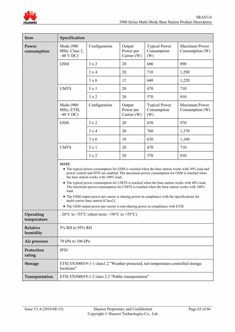
SRAN3.0
3900 Series Multi-Mode Base Station Product Description
Issue V1.4 (2010-08-15) Huawei Proprietary and Confidential Copyright © Huawei Technologies Co., Ltd.
Page 63 of 66
Item Specification
Mode (900 MHz, Class 2, –48 V DC)
Configuration Output Power per Carrier (W)
Typical Power Consumption (W)
Maximum Power Consumption (W)
3 x 2 20 600 890
3 x 4 20 710 1,290
GSM
3 x 6 12 640 1,220
3 x 1 20 470 710 UMTS
3 x 2 20 570 910
Mode (900 MHz, ETSI, –48 V DC)
Configuration Output Power per Carrier (W)
Typical Power Consumption (W)
Maximum Power Consumption (W)
3 x 2 20 650 970
3 x 4 20 760 1,370
GSM
3 x 6 10 630 1,160
3 x 1 20 470 710 UMTS 3 x 2 20 570 910
Power consumption
NOTE The typical power consumption for GSM is reached when the base station works with 30% load and power control and DTX are enabled. The maximum power consumption for GSM is reached when the base station works with 100% load.
The typical power consumption for UMTS is reached when the base station works with 40% load. The maximum power consumption for UMTS is reached when the base station works with 100% load.
The GSM output power per carrier is sharing power in compliance with the specifications for multi-carrier base station (Class2).
The GSM output power per carrier is non-sharing power in compliance with ETSI.
Operating temperature
–20°C to +55°C (short-term: +50°C to +55°C)
Relative humidity
5% RH to 95% RH
Air pressure 70 kPa to 106 kPa
Protection rating
IP20
Storage ETSI EN300019-1-1 class1.2 "Weather protected, not temperature-controlled storage locations"
Transportation ETSI EN300019-1-2 class 2.3 "Public transportation"

SRAN3.0
3900 Series Multi-Mode Base Station Product Description
Issue V1.4 (2010-08-15) Huawei Proprietary and Confidential Copyright © Huawei Technologies Co., Ltd.
Page 64 of 66
Item Specification
Anti-seismic performance
IEC 60068-2-57 (1999-11) Environmental testing -Part 2-57: Tests -Test Ff: Vibration -Time-history method YD5083-99: Interim Provisions for Test of Anti-seismic Performances of Telecommunications Equipment (telecom industry standard in People's Republic of China)
Anti-earthquake performance
ETSI EN 300019-1-3: "Earthquake"
EMC The BTS3900L meets the Electro Magnetic Compatibility (EMC) requirements and complies with the following standards: R&TTE Directive 1999/5/EC
R&TTE Directive 1999/5/EC R&TTE Directive 89/336/EEC ETSI EN 301489-1/8/23 3GPP TS 25.113 ETSI EN 301908-1 ITU-T SM 329-10 FCC PART15

SRAN3.0
3900 Series Multi-Mode Base Station Product Description
Issue V1.4 (2010-08-15) Huawei Proprietary and Confidential Copyright © Huawei Technologies Co., Ltd.
Page 65 of 66
A Acronyms and Abbreviations
Abbreviation Full Name
3GPP 3rd Generation Partnership Project
AC Alternating Current
AMR Adaptive Multi Rate
APM Advanced Power Module
ASIC Application Specific Integrated Circuit
ATM Asynchronous Transfer Mode
BER Bit Error Rate
BITS Building Integrated Timing Supply System
CE Channel Elements
CPRI Common Public Radio Interface
DC Direct Current
DHCP Dynamic Host Confiration Protocol
DL Downlink
EMC Electromagnetic Compatibility
ETS European Telecommunication Standard
ETSI European Telecommunications Standards Institute
FE Fast Ethernet
GPS Global Positioning System
HSDPA High Speed Downlink Packet Access
HSUPA High Speed Uplink Packet Access
IEC International Electrotechnical Commission
IMA Inverse Multiplexing on ATM

SRAN3.0
3900 Series Multi-Mode Base Station Product Description
Issue V1.4 (2010-08-15) Huawei Proprietary and Confidential Copyright © Huawei Technologies Co., Ltd.
Page 66 of 66
LMT Local Maintenance Terminal
MML Man Machine Language
MSR Multi-Standard Radio
OM Operation and Maintenance
PAs Power Amplifiers
PSU Power Supply Unit
PMU Power Monitoring Unit
QoS Quality of Service
RAN Radio Access Network
RET Remote Electrical antenna Tilt
RF Radio Frequency
RFC Radio Frequency Cabinet
RNC Radio Network Controller
RRU Remote Radio Unit
RX Receive
TMA Tower Mounted Amplifier
TX Transmit
STM-1 Synchronous Transport Mode-1
UE User Equipment
UL Uplink
UMTS Universal Mobile Telecommunications System
UTRP Universal Transmission Processing unit
WCDMA Wideband Code Division Multiple Access


![Technical Article - Nutaq multi-mode software-defined radio (SDR), advanced ... For the PICO BTS class, ... the burst below 0.1 parts per million (ppm) [1]](https://img.pdfslide.us/doc/110x75/5aab53a07f8b9aa9488bde99/technical-article-nutaq-multi-mode-software-defined-radio-sdr-advanced-.jpg)