Embed Size (px)
Citation preview
www.cdautomation.comRevo PN Catalogo 2018
Release n. 1
www.cdautomation.com
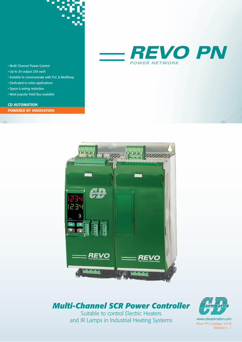
Multi-Channel SCR Power ControllerSuitable to control Electric Heaters
and IR Lamps in Industrial Heating Systems
POWERED BY INNOVATION
• Multi Channel Power Control
• Up to 24 output 25A each
• Suitable to communicate with PLC & Multiloop
• Dedicated to solve applications
• Space & wiring reduction
• Most popular Field Bus available
CD AUTOMATION

2
REVO PN POWER NETWORKCreated specifically for industrial multi-zone applications, REVO
PN can be configured to control between 4 and 24 channels/
zones. Typically, each zone is sized for 25A but by using the front
panel connector, loads of up to 210A can be connected.
The REVO PN unit is designed to handle applications with
multiple zones. This enhanced unit, thanks to a particular
algorithm, minimizes your energy costs through the
synchronization and the power limit for each zone.
Revo PN keeps your instantaneous power within the limits of
your electricity supply contract.
IMPORTANT POWER CONTROL FUNCTIONALITY IS OFFERED BY REVO PN INCLUDING:• Elimination of power overshoot
• Power factor maintained close to 1
• Stay connected with the most popular Field Bus protocols
• Eliminate use of PLC output modules by using comms for
Power to CPU connections
• Alarm notification per zone of heater break and thyristor short
circuit
• Product footprint for 24 zone package 60% less than using
standard thyristor stacks
• Dramatic savings with less wiring & smaller cabinet enclosures
• REVO PN’s considered design not only helps you save start-up
costs but ensures you keep on saving money throughout the
products lifetime.
HAVE YOU CONSIDERED HOW POWER PEAKS COULD BE A PROBLEM TO YOUR BUSINESS?
WITHOUT POWER CONTROL OPTIMISATION
WITH POWER CONTROL OPTIMISATION

33
EACH ZONE INCLUDE:
• Thyristor Units with high I2T • Communication
• 480V Max Voltage • Synchronizing Circuit
• Integrated Extra Rapid fuse • Digital Input and Relay Output
8 - 16 ONE PHASE CHANNEL
12 - 24 THREE PHASE CHANNEL20 - 24 ONE PHASE CHANNEL
4 - 8 ONE PHASE CHANNEL
REVO PN FAMILY

4
x24
CPU TC AI DO
x24
x24
F
N
F
N
x24
x24
x24
CPU TC REVO PN
BUS DI CAMPO F
N
DRAMATIC REDUCTION IN CABLE WIRING
COMPARE THE NEW REVO PN TO A TRADITIONAL PLC SYSTEM AND YOU SAVE:• 6 wires for each zone.
• Each wire takes 11 minutes (see diagram shown).
• For each zone you save 6 wires x 11 minutes = 66 minutes in total.
TOTAL TIME SAVED OF 26,4 HOURS FOR 24 CHANNEL!
• SO HOW MANY ZONES/LOOPS • DO YOU SELL IN ONE YEAR?• MAKE A CALCULATION OF WHAT YOU CAN SAVE.• AND YOU HAVE ONLY ONE DECISION TO MAKE.
TRADITIONAL SYSTEM REVO PN SYSTEM
WHY 11 MIN. FOR EACH WIRE?Schematics reading and understanding,distances and path measuring.Wire cutting - Wire stripping - Wire labelingCrimpling the lug with the copperTerminal block wiring

55
READ WRITE
Set Point Set Point
Alarm One by one Configuration Parameters
Voltage
Power
Current
Heater Break Alarm
SCR Short Circuit Alarm
CONNECTIVITY AND CONFIGURATION
CONTROL ROOM
SMART PHONE
TEMPERATURE CONTROLLER
MULTILOOP
HMI GPRS MODEM
WIFI HOTSPOT
WEB PC
PLC
GPRS

6
INFRARED OVEN AND THERMOFORMING
INFRARED LAMPS WITH MEDIUM AND SHORT WAVE FORMREVO PN is the best solution to control all types of infrared lamps.
The robust junction with high I2t allows it to drive short-wave IR
lamps.
There are several types of soft start, which cancels the
phenomenon of flickering.
The synchronization makes the power factor close to one.
Power Network voltage fluctuations are compensated instantly via
the feedback in the unit.
REVO PN’S COMPACT DESIGN RESULTS IN MULTIPLE UNITS IN SMALL FOOTPRINT SIZEIn the control panel shown on the right, a 800x2000 mm layout
contains 168 zones of 25A.
The units can be connected via communication to a PLC or
to a multi loop temperature controller.
The connection to ProfiNet® can be done via switches or chains by
using the two RJ 45 ports.
The main components of the power part are already included
within each module (Fuse, Thyristor and Current Transformer).
You will only have to wrap the input wires for input and output for
each heating element.
Communication will provide the main diagnostics on load,
scr and fuses.

77
1
2
3
4
PLASTIC EXTRUSION MACHINE
AUTOMATION SOLUTION FOR EXTRUSION LINES
• Scalable power management, single extruder or full line.
• Modules of 12 or 24 zones already divided into three phases or one phase from 4 to 24 zones.
• Cyclic reading and writing of process variables.
• Short circuit SCR and load brake diagnostics.
• Reduced power consumption due to power grid fluctuations through live control.
• Maintains instantaneous power in the contractual limits with a power factor close to one.
• Strong bulk reduction and cabling for co-extrusion systems that can pass 100 zones.
1 SCADA System2 PLC: Motion & Temperature Control3 Heating Power Control4 Extrusion Lines

8
x8
N
SSR
TA
N
F
EASY MAINTENANCEEASY FUSE REPLACEMENT
GENERAL FEATURES
GENERAL FEATURES
Cover and Socket material: PolymericV2
Utilization Category AC-51 AC-55b
IP Code 20
Method of Connecting See pages 10/11
Delay switch ON/OFF time: 1/2 Period Max
INPUT FEATURES
Logic input SSR 7 ÷ 30Vdc 9mA Max (ON ≥7Vdc OFF < 6Vdc)
L1 - L2 - L3 Power Input 370 - 480V
OUTPUT FEATURES (power device):
Nominal current in continuous service Max 25A for each load
Max peak current (10ms) 700A
Nominal Voltage range Ue 24 - 600V
Repetitive peak reverse voltage 1200V (480V) 1600V (600V)
Latching current 250mA
Leakage current 15mA eff
FUSE I²T value suggested at 500Vac tp=10msec 1260 A2s
Frequency range 47 - 70Hz
Total Power loss for 8 zone (I=Inom) 350W
Isolation Voltage Ui 2500Vac
N° 8 out SSR + CT input Option T digit 16 on ordring code
Option: SSR Output terminal expansion to control up to N°8 external 1PH units

99
x8
WW W
H H H
D D D
FIXING HOLES
8 ZONES 16 ZONES 24 ZONES
8 ZONES 16 ZONES 24 ZONES
HIGH I2T SCR JUNCTION
DIMENSION AND CUT-OUT
SIZE W (mm) D (mm) H (mm) WHEIGHT (kg)
8 Zones 93 170 273 3.6
16 Zones 186 170 273 7
24 Zones 281 170 274 10.6
10
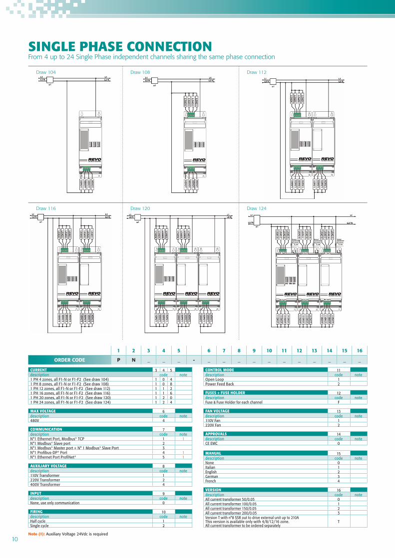
CURRENT 3 4 5description code note1 PH 4 zones, all F1-N or F1-F2 (See draw 104) 1 0 41 PH 8 zones, all F1-N or F1-F2 (See draw 108) 1 0 81 PH 12 zones, all F1-N or F1-F2 (See draw 112) 1 1 21 PH 16 zones, all F1-N or F1-F2 (See draw 116) 1 1 61 PH 20 zones, all F1-N or F1-F2 (See draw 120) 1 2 01 PH 24 zones, all F1-N or F1-F2 (See draw 124) 1 2 4
MAX VOLTAGE 6description code note480V 4
COMMUNICATION 7description code noteN°1 Ethernet Port, Modbus® TCP 1 1N°1 Modbus® Slave port 2N°1 Modbus® Master port + N° 1 Modbus® Slave Port 3N°1 Profibus-DP® Port 4 1N°1 Ethernet Port ProfiNet® 5 1
AUXILIARY VOLTAGE 8description code note110V Transformer 1220V Transformer 2400V Transformer 4
INPUT 9description code noteNone, use only communication 0
FIRING 10description code noteHalf cycle 1Single cycle 2
CONTROL MODE 11description code noteOpen Loop 1Power Feed Back 2
FUSES + FUSE HOLDER 12description code noteFuse & Fuse Holder for each channel F
FAN VOLTAGE 13description code note110V Fan 1220V Fan 2
APPROVALS 14description code noteCE EMC 0
MANUAL 15description code noteNone 0Italian 1English 2German 3French 4
VERSION 16description code noteAll current transformer 50/0.05 0All current transformer 100/0.05 1All current transformer 150/0.05 2All current transformer 200/0.05 3Version T with n°8 SSR out to drive external unit up to 210AThis version is available only with 4/8/12/16 zone. All current transformer to be ordered separately
T
SINGLE PHASE CONNECTIONFrom 4 up to 24 Single Phase independent channels sharing the same phase connection
1 2 3 4 5 6 7 8 9 10 11 12 13 14 15 16
ORDER CODE P N _ _ _ - _ _ _ _ _ _ _ _ _ _ _
Draw 104
Draw 116
Draw 108
Draw 120
Draw 112
Draw 124
Note (1): Auxiliary Voltage 24Vdc is required

1111
CURRENT 3 4 5description code note3 PH 12 zones (n°4 zones F1-N; n°4 zones F2-N; n°4 zones F3-N) (draw 412) 4 1 23 PH 24 zones (n°8 zones F1-N; n°8 zones F2-N; n°8 zones F3-N) (draw 424) 4 2 43 PH 12 zones (n°4 zones F1-F2; n°4 zones F2-F3; n°4 zones F1-F3) (draw 612) 6 1 23 PH 24 zones (n°8 zones F1-F2; n°8 zones F2-F3; n°8 zones F1-F3) (draw 624) 6 2 4
MAX VOLTAGE 6description code note480V 4
COMMUNICATION 7description code noteN°1 Ethernet Port, Modbus® TCP 1 1N°1 Modbus® Slave port 2N°1 Modbus® Master port + N°1 Modbus® Slave Port 3N°1 Profibus-DP® Port 4 1N°1 Ethernet Port ProfiNet® 5 1
AUXILIARY VOLTAGE 8description code note220V Transformer 2400V Transformer 4
INPUT 9description code noteNone, use only communication 0
FIRING 10description code noteHalf cycle 1Single cycle 2
CONTROL MODE 11description code noteOpen Loop 1Power Feed Back 2
FUSES + FUSE HOLDER 12description code noteFuse & Fuse Holder for each channel F
FAN VOLTAGE 13description code note110V Fan 1220V Fan 2
APPROVALS 14description code noteCE EMC 0
MANUAL 15description code noteNone 0Italian 1English 2German 3French 4
VERSION 16description code noteAll current transformer 50/0.05 0All current transformer 100/0.05 1All current transformer 150/0.05 2All current transformer 200/0.05 3
THREE PHASE CONNECTION12 or 24 Single Phase independent channels balanced on the three different phases
1 2 3 4 5 6 7 8 9 10 11 12 13 14 15 16
ORDER CODE P N _ _ _ - _ _ _ _ _ _ _ _ _ _ _
Draw 424 Draw 624
Draw 412 Draw 612
MODBUS® is a registered trademark of Schneider Automation, Inc. PROFIBUS-DP® is a registered trademark of PROFIBUS Nutzerorganisation e.V. PROFINET® is a registered trademark of PROFINET International (PI). All trademarks are the property of their respective owners.
Note (1): Auxiliary Voltage 24Vdc is required

ItalyCD Automation SrlVia Picasso, 34/3620025 Legnano MIItalyT +39 0331 577479F +39 0331 [email protected] www.cdautomation.com
CD Automation Srl (Facility)20023 Cantalupo MIItaly
IndiaM/s Toshcon CD Automation Pvt. Ltd.H1 - 75 Gegal Industrial AreaAjmer - 305023 (Raj.)IndiaT +91 145 2791112T +91 145 6450601/2/[email protected] www.cdautomation.in
EnglandCD Automation UK LtdUnit 9 Harvington Business ParkBrampton Road, EastbourneEast Sussex, BN22 9BNEnglandT +44 1323 [email protected]