Embed Size (px)
Citation preview
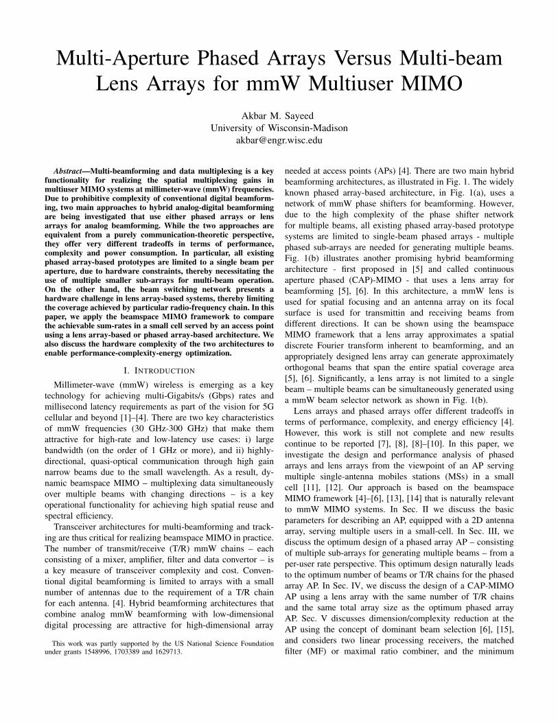
Multi-Aperture Phased Arrays Versus Multi-beamLens Arrays for mmW Multiuser MIMO
Akbar M. SayeedUniversity of Wisconsin-Madison
Abstract—Multi-beamforming and data multiplexing is a keyfunctionality for realizing the spatial multiplexing gains inmultiuser MIMO systems at millimeter-wave (mmW) frequencies.Due to prohibitive complexity of conventional digital beamform-ing, two main approaches to hybrid analog-digital beamformingare being investigated that use either phased arrays or lensarrays for analog beamforming. While the two approaches areequivalent from a purely communication-theoretic perspective,they offer very different tradeoffs in terms of performance,complexity and power consumption. In particular, all existingphased array-based prototypes are limited to a single beam peraperture, due to hardware constraints, thereby necessitating theuse of multiple smaller sub-arrays for multi-beam operation.On the other hand, the beam switching network presents ahardware challenge in lens array-based systems, thereby limitingthe coverage achieved by particular radio-frequency chain. In thispaper, we apply the beamspace MIMO framework to comparethe achievable sum-rates in a small cell served by an access pointusing a lens array-based or phased array-based architecture. Wealso discuss the hardware complexity of the two architectures toenable performance-complexity-energy optimization.
I. INTRODUCTION
Millimeter-wave (mmW) wireless is emerging as a keytechnology for achieving multi-Gigabits/s (Gbps) rates andmillisecond latency requirements as part of the vision for 5Gcellular and beyond [1]–[4]. There are two key characteristicsof mmW frequencies (30 GHz-300 GHz) that make themattractive for high-rate and low-latency use cases: i) largebandwidth (on the order of 1 GHz or more), and ii) highly-directional, quasi-optical communication through high gainnarrow beams due to the small wavelength. As a result, dy-namic beamspace MIMO – multiplexing data simultaneouslyover multiple beams with changing directions – is a keyoperational functionality for achieving high spatial reuse andspectral efficiency.
Transceiver architectures for multi-beamforming and track-ing are thus critical for realizing beamspace MIMO in practice.The number of transmit/receive (T/R) mmW chains – eachconsisting of a mixer, amplifier, filter and data convertor – isa key measure of transceiver complexity and cost. Conven-tional digital beamforming is limited to arrays with a smallnumber of antennas due to the requirement of a T/R chainfor each antenna. [4]. Hybrid beamforming architectures thatcombine analog mmW beamforming with low-dimensionaldigital processing are attractive for high-dimensional array
This work was partly supported by the US National Science Foundationunder grants 1548996, 1703389 and 1629713.
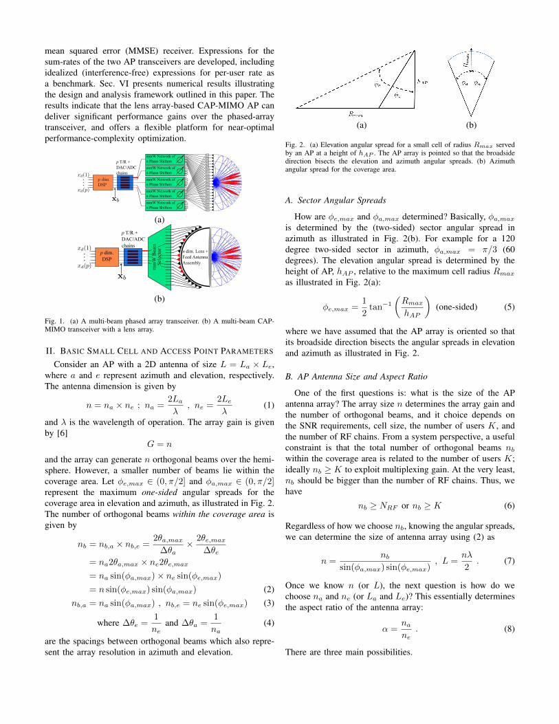
needed at access points (APs) [4]. There are two main hybridbeamforming architectures, as illustrated in Fig. 1. The widelyknown phased array-based architecture, in Fig. 1(a), uses anetwork of mmW phase shifters for beamforming. However,due to the high complexity of the phase shifter networkfor multiple beams, all existing phased array-based prototypesystems are limited to single-beam phased arrays - multiplephased sub-arrays are needed for generating multiple beams.Fig. 1(b) illustrates another promising hybrid beamformingarchitecture - first proposed in [5] and called continuousaperture phased (CAP)-MIMO - that uses a lens array forbeamforming [5], [6]. In this architecture, a mmW lens isused for spatial focusing and an antenna array on its focalsurface is used for transmittin and receiving beams fromdifferent directions. It can be shown using the beamspaceMIMO framework that a lens array approximates a spatialdiscrete Fourier transform inherent to beamforming, and anappropriately designed lens array can generate approximatelyorthogonal beams that span the entire spatial coverage area[5], [6]. Significantly, a lens array is not limited to a singlebeam – multiple beams can be simultaneously generated usinga mmW beam selector network as shown in Fig. 1(b).
Lens arrays and phased arrays offer different tradeoffs interms of performance, complexity, and energy efficiency [4].However, this work is still not complete and new resultscontinue to be reported [7], [8], [8]–[10]. In this paper, weinvestigate the design and performance analysis of phasedarrays and lens arrays from the viewpoint of an AP servingmultiple single-antenna mobiles stations (MSs) in a smallcell [11], [12]. Our approach is based on the beamspaceMIMO framework [4]–[6], [13], [14] that is naturally relevantto mmW MIMO systems. In Sec. II we discuss the basicparameters for describing an AP, equipped with a 2D antennaarray, serving multiple users in a small-cell. In Sec. III, wediscuss the optimum design of a phased array AP – consistingof multiple sub-arrays for generating multiple beams – from aper-user rate perspective. This optimum design naturally leadsto the optimum number of beams or T/R chains for the phasedarray AP. In Sec. IV, we discuss the design of a CAP-MIMOAP using a lens array with the same number of T/R chainsand the same total array size as the optimum phased arrayAP. Sec. V discusses dimension/complexity reduction at theAP using the concept of dominant beam selection [6], [15],and considers two linear processing receivers, the matchedfilter (MF) or maximal ratio combiner, and the minimum
mean squared error (MMSE) receiver. Expressions for thesum-rates of the two AP transceivers are developed, includingidealized (interference-free) expressions for per-user rate asa benchmark. Sec. VI presents numerical results illustratingthe design and analysis framework outlined in this paper. Theresults indicate that the lens array-based CAP-MIMO AP candeliver significant performance gains over the phased-arraytransceiver, and offers a flexible platform for near-optimalperformance-complexity optimization.
(a)
(b)
Fig. 1. (a) A multi-beam phased array transceiver. (b) A multi-beam CAP-MIMO transceiver with a lens array.
II. BASIC SMALL CELL AND ACCESS POINT PARAMETERS
Consider an AP with a 2D antenna of size L = La × Le,where a and e represent azimuth and elevation, respectively.The antenna dimension is given by
n = na × ne ; na =2Laλ
, ne =2Leλ
(1)
and λ is the wavelength of operation. The array gain is givenby [6]
G = n
and the array can generate n orthogonal beams over the hemi-sphere. However, a smaller number of beams lie within thecoverage area. Let φe,max ∈ (0, π/2] and φa,max ∈ (0, π/2]represent the maximum one-sided angular spreads for thecoverage area in elevation and azimuth, as illustrated in Fig. 2.The number of orthogonal beams within the coverage area isgiven by
nb = nb,a × nb,e =2θa,max
∆θa× 2θe,max
∆θe= na2θa,max × ne2θe,max= na sin(φa,max)× ne sin(φe,max)
= n sin(φe,max) sin(φa,max) (2)nb,a = na sin(φa,max) , nb,e = ne sin(φe,max) (3)
where ∆θe =1
neand ∆θa =
1
na(4)
are the spacings between orthogonal beams which also repre-sent the array resolution in azimuth and elevation.
(a) (b)
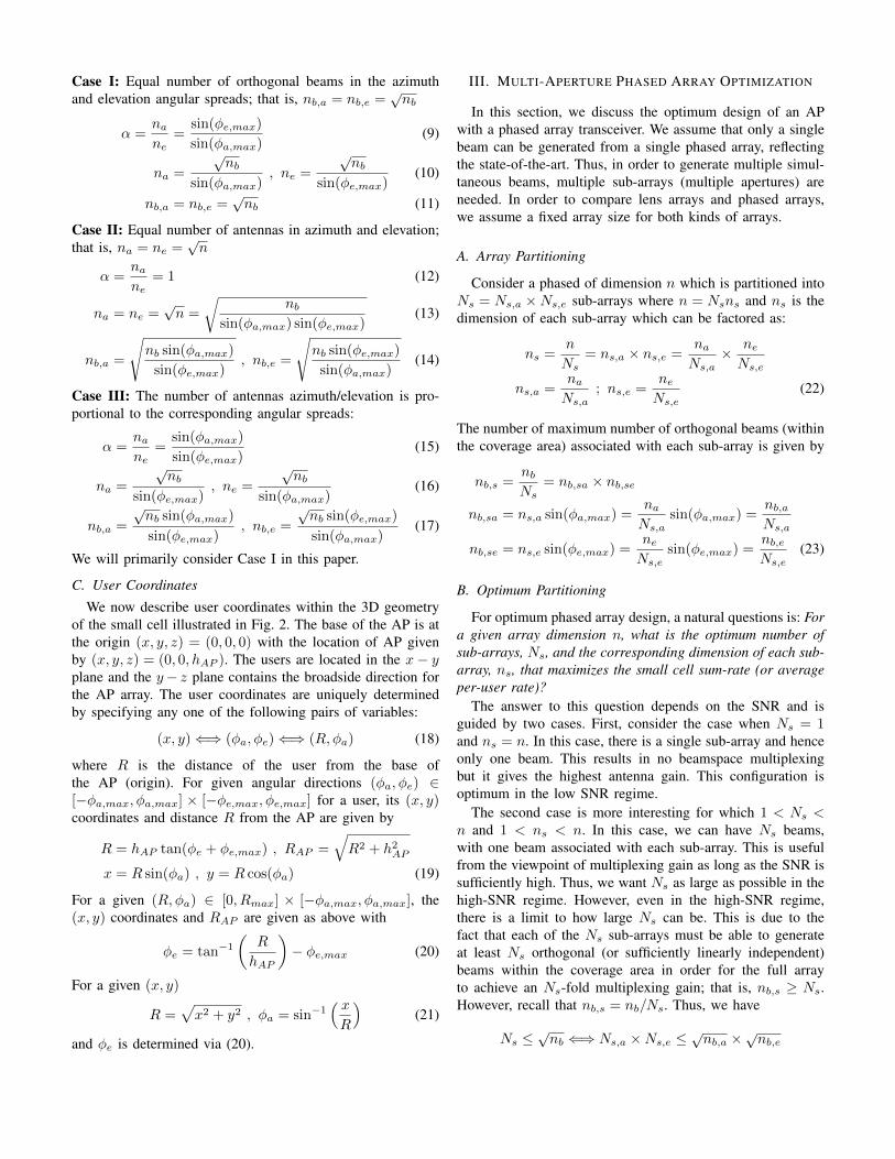
Fig. 2. (a) Elevation angular spread for a small cell of radius Rmax servedby an AP at a height of hAP . The AP array is pointed so that the broadsidedirection bisects the elevation and azimuth angular spreads. (b) Azimuthangular spread for the coverage area.
A. Sector Angular Spreads
How are φe,max and φa,max determined? Basically, φa,maxis determined by the (two-sided) sector angular spread inazimuth as illustrated in Fig. 2(b). For example for a 120degree two-sided sector in azimuth, φa,max = π/3 (60degrees). The elevation angular spread is determined by theheight of AP, hAP , relative to the maximum cell radius Rmaxas illustrated in Fig. 2(a):
φe,max =1
2tan−1
(RmaxhAP
)(one-sided) (5)
where we have assumed that the AP array is oriented so thatits broadside direction bisects the angular spreads in elevationand azimuth as illustrated in Fig. 2.
B. AP Antenna Size and Aspect Ratio
One of the first questions is: what is the size of the APantenna array? The array size n determines the array gain andthe number of orthogonal beams, and it choice depends onthe SNR requirements, cell size, the number of users K, andthe number of RF chains. From a system perspective, a usefulconstraint is that the total number of orthogonal beams nbwithin the coverage area is related to the number of users K;ideally nb ≥ K to exploit multiplexing gain. At the very least,nb should be bigger than the number of RF chains. Thus, wehave
nb ≥ NRF or nb ≥ K (6)
Regardless of how we choose nb, knowing the angular spreads,we can determine the size of antenna array using (2) as
n =nb
sin(φa,max) sin(φe,max), L =
nλ
2. (7)
Once we know n (or L), the next question is how do wechoose na and ne (or La and Le)? This essentially determinesthe aspect ratio of the antenna array:
α =nane
. (8)
There are three main possibilities.
Case I: Equal number of orthogonal beams in the azimuthand elevation angular spreads; that is, nb,a = nb,e =
√nb
α =nane
=sin(φe,max)
sin(φa,max)(9)
na =
√nb
sin(φa,max), ne =
√nb
sin(φe,max)(10)
nb,a = nb,e =√nb (11)
Case II: Equal number of antennas in azimuth and elevation;that is, na = ne =
√n
α =nane
= 1 (12)
na = ne =√n =
√nb
sin(φa,max) sin(φe,max)(13)
nb,a =
√nb sin(φa,max)
sin(φe,max), nb,e =
√nb sin(φe,max)
sin(φa,max)(14)
Case III: The number of antennas azimuth/elevation is pro-portional to the corresponding angular spreads:
α =nane
=sin(φa,max)
sin(φe,max)(15)
na =
√nb
sin(φe,max), ne =
√nb
sin(φa,max)(16)
nb,a =
√nb sin(φa,max)
sin(φe,max), nb,e =
√nb sin(φe,max)
sin(φa,max)(17)
We will primarily consider Case I in this paper.
C. User Coordinates
We now describe user coordinates within the 3D geometryof the small cell illustrated in Fig. 2. The base of the AP is atthe origin (x, y, z) = (0, 0, 0) with the location of AP givenby (x, y, z) = (0, 0, hAP ). The users are located in the x− yplane and the y− z plane contains the broadside direction forthe AP array. The user coordinates are uniquely determinedby specifying any one of the following pairs of variables:
(x, y)⇐⇒ (φa, φe)⇐⇒ (R,φa) (18)
where R is the distance of the user from the base ofthe AP (origin). For given angular directions (φa, φe) ∈[−φa,max, φa,max] × [−φe,max, φe,max] for a user, its (x, y)coordinates and distance R from the AP are given by
R = hAP tan(φe + φe,max) , RAP =√R2 + h2AP
x = R sin(φa) , y = R cos(φa) (19)
For a given (R,φa) ∈ [0, Rmax] × [−φa,max, φa,max], the(x, y) coordinates and RAP are given as above with
φe = tan−1(
R
hAP
)− φe,max (20)
For a given (x, y)
R =√x2 + y2 , φa = sin−1
( xR
)(21)
and φe is determined via (20).
III. MULTI-APERTURE PHASED ARRAY OPTIMIZATION
In this section, we discuss the optimum design of an APwith a phased array transceiver. We assume that only a singlebeam can be generated from a single phased array, reflectingthe state-of-the-art. Thus, in order to generate multiple simul-taneous beams, multiple sub-arrays (multiple apertures) areneeded. In order to compare lens arrays and phased arrays,we assume a fixed array size for both kinds of arrays.
A. Array Partitioning
Consider a phased of dimension n which is partitioned intoNs = Ns,a ×Ns,e sub-arrays where n = Nsns and ns is thedimension of each sub-array which can be factored as:
ns =n
Ns= ns,a × ns,e =
naNs,a
× neNs,e
ns,a =naNs,a
; ns,e =neNs,e
(22)
The number of maximum number of orthogonal beams (withinthe coverage area) associated with each sub-array is given by
nb,s =nbNs
= nb,sa × nb,se
nb,sa = ns,a sin(φa,max) =naNs,a
sin(φa,max) =nb,aNs,a
nb,se = ns,e sin(φe,max) =neNs,e
sin(φe,max) =nb,eNs,e
(23)
B. Optimum Partitioning
For optimum phased array design, a natural questions is: Fora given array dimension n, what is the optimum number ofsub-arrays, Ns, and the corresponding dimension of each sub-array, ns, that maximizes the small cell sum-rate (or averageper-user rate)?
The answer to this question depends on the SNR and isguided by two cases. First, consider the case when Ns = 1and ns = n. In this case, there is a single sub-array and henceonly one beam. This results in no beamspace multiplexingbut it gives the highest antenna gain. This configuration isoptimum in the low SNR regime.
The second case is more interesting for which 1 < Ns <n and 1 < ns < n. In this case, we can have Ns beams,with one beam associated with each sub-array. This is usefulfrom the viewpoint of multiplexing gain as long as the SNR issufficiently high. Thus, we want Ns as large as possible in thehigh-SNR regime. However, even in the high-SNR regime,there is a limit to how large Ns can be. This is due to thefact that each of the Ns sub-arrays must be able to generateat least Ns orthogonal (or sufficiently linearly independent)beams within the coverage area in order for the full arrayto achieve an Ns-fold multiplexing gain; that is, nb,s ≥ Ns.However, recall that nb,s = nb/Ns. Thus, we have
Ns ≤√nb ⇐⇒ Ns,a ×Ns,e ≤
√nb,a ×
√nb,e
and for sufficiently high SNR, the optimum (largest) value ofNs is given by
Ns,opt =√nb (24)
m
Ns,a,opt =√nb,a =
√na sin(φa,max)
Ns,e,opt =√nb,e =
√ne sin(φe,max) (25)
For the above optimum array partitioning, we have the follow-ing dimensions for each sub-array
ns,opt =n
Ns,opt=
n√nb
=
√nb
sin(φa,max) sin(φe,max)
= ns,a,opt × ns,e,opt (26)
ns,a,opt =na
Ns,a,opt=
na√nb,a
=
√na
sin(φa,max)(27)
ns,e,opt =ne
Ns,e,opt=
ne√nb,e
=
√ne
sin(φe,max)(28)
In terms of the beams generated by each sub-array, we have
nb,s,opt =nb
Ns,opt=√nb = Ns,opt
=√nb,sa,opt ×
√nb,se,opt (29)
nb,sa,opt =nb,a
Ns,a,opt=
nb,a√nb,a
= Ns,a,opt
=√na sin(φa,max) (30)
nb,se,opt =nb,e
Ns,e,opt=
nb,e√nb,e
= Ns,e,opt
=√ne sin(φe,max) (31)
Recall that an AP with an Ns-aperture phased array cangenerate Ns simultaneous beams, each driven by one of theNRF = Ns RF chains. For K users to serve in the coveragearea, the number of users per RF chain/beam is given by
KRF =K
Ns=
K√nb
where the last equality is for the optimum design. Thus, thetotal bandwidth W is shared by KRF users on average ineach beam. The idealized (interference-free) per-user uplinkrate (bps) at a distance R is given by
CPA(R) =W
KRFlog2
(1 +
PGsγ
NoW/KRF
), γ =
(λ
4πR
)2
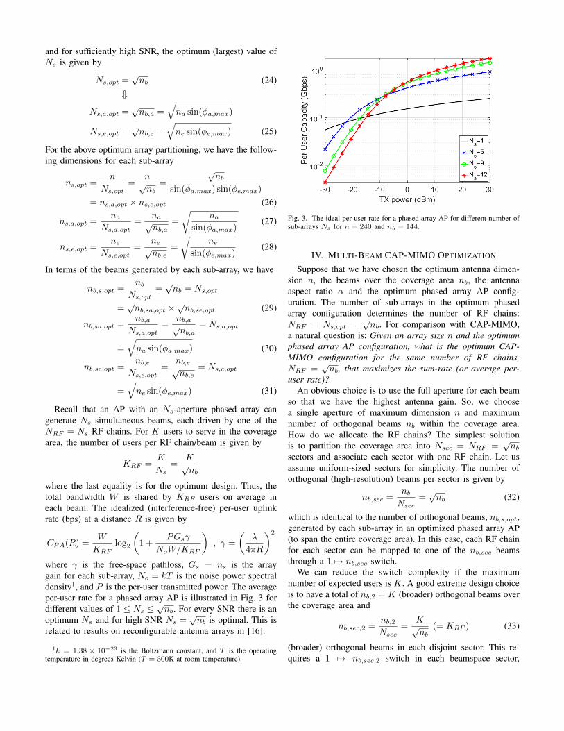
where γ is the free-space pathloss, Gs = ns is the arraygain for each sub-array, No = kT is the noise power spectraldensity1, and P is the per-user transmitted power. The averageper-user rate for a phased array AP is illustrated in Fig. 3 fordifferent values of 1 ≤ Ns ≤
√nb. For every SNR there is an
optimum Ns and for high SNR Ns =√nb is optimal. This is
related to results on reconfigurable antenna arrays in [16].
1k = 1.38 × 10⁻²³ is the Boltzmann constant, and T is the operatingtemperature in degrees Kelvin (T = 300K at room temperature).
Fig. 3. The ideal per-user rate for a phased array AP for different number ofsub-arrays Ns for n = 240 and nb = 144.
IV. MULTI-BEAM CAP-MIMO OPTIMIZATION
Suppose that we have chosen the optimum antenna dimen-sion n, the beams over the coverage area nb, the antennaaspect ratio α and the optimum phased array AP config-uration. The number of sub-arrays in the optimum phasedarray configuration determines the number of RF chains:NRF = Ns,opt =
√nb. For comparison with CAP-MIMO,
a natural question is: Given an array size n and the optimumphased array AP configuration, what is the optimum CAP-MIMO configuration for the same number of RF chains,NRF =
√nb, that maximizes the sum-rate (or average per-
user rate)?An obvious choice is to use the full aperture for each beam
so that we have the highest antenna gain. So, we choosea single aperture of maximum dimension n and maximumnumber of orthogonal beams nb within the coverage area.How do we allocate the RF chains? The simplest solutionis to partition the coverage area into Nsec = NRF =
√nb
sectors and associate each sector with one RF chain. Let usassume uniform-sized sectors for simplicity. The number oforthogonal (high-resolution) beams per sector is given by
nb,sec =nbNsec
=√nb (32)
which is identical to the number of orthogonal beams, nb,s,opt,generated by each sub-array in an optimized phased array AP(to span the entire coverage area). In this case, each RF chainfor each sector can be mapped to one of the nb,sec beamsthrough a 1 7→ nb,sec switch.
We can reduce the switch complexity if the maximumnumber of expected users is K. A good extreme design choiceis to have a total of nb,2 = K (broader) orthogonal beams overthe coverage area and
nb,sec,2 =nb,2Nsec
=K√nb
(= KRF ) (33)
(broader) orthogonal beams in each disjoint sector. This re-quires a 1 7→ nb,sec,2 switch in each beamspace sector,
which would be of lower complexity as long as K ≤ nb,which would typically be the case for the high-resolutionbeams; see (6). Note that, in this case, the feed antennas willhave to designed appropriately to generate broader beams. Ingeneral, the size/area of the feed antenna is proportional tothe beamwidth. The number of (high resolution) orthogonalbeams within the broader beam is given by
nb,f =nb,secnb,sec,2
=nbK
(34)
and thus the new composite feed antennas would cover the areaof about nb,f (highest resolution) feed antennas to generatesa correspondingly wide beam to avoid holes in coverage.
In general, for a given number of users K and the antennasize n (or equivalently nb), we have a whole family of choicesfor the switch dimension (SD)
K√nb≤ SD ≤
√nb (35)
with the corresponding composite feed size (relative to thehigh-resolution feed size) given by
1 ≤ nb,f =nb,secSD
≤ nbK
(36)
which ranges between nb,f = 1 (for the largest SD =√nb)
and nb,f = nb
K (for the smallest SD = K√nb
). The number ofbeams in azimuth and elevation in a composite feed are relatedthrough the choice of the antenna aspect ratio α as discussedin Sec. II-B. For equal beams in the azimuth and elevationdirections (Case I), we have
nb,fa = nb,fe =√nb,f .
The idea of a composite is also attractive from the viewpointof maximizing the power transfer from the feed to the lens.It can be shown that, in order to get the best coupling tothe aperture, the feed size needs to be a bit larger than thatspecified by the critical spacing.
For a given number of RF chains, there are other possibili-ties as well for CAP-MIMO. For example, multiple aperturesmay be more attractive from an implementation viewpoint.However, multiple apertures will usually result in a loss ofSNR. But it will still be less than that in a phased array systemas long as the number of apertures used in CAP-MIMO is lessthat in the phased array system.
One interesting possibility of multiple apertures in CAP-MIMO is related to the feed complexity. For a given nb,f > 1,typically a composite feed with an area of about nb,f critically-spaced (high resolution) feeds would be needed for generat-ing a broader beam. However, an alternative is to use nb,fapertures, with each aperture of a smaller size by a factorof nb,f compared to the maximum aperture size, resultingin correspondingly larger beams. In this case, we can useregular, single-beam (high-resolution) feeds. The signal foreach (broader) beam is now generated coherently by multipleapertures, and the combined signal would compensate for theSNR loss due to smaller apertures/wider beams from eachaperture. However, the wider beams will result in higherinterference.
V. SYSTEM MODEL AND BEAMSPACE PROCESSING AT AP
Consider a small cell in which an AP with a 2D uniformplanar array of dimension n = na × ne serves K users in asector of radius Rmax and angular spreads φa,max and φe,max.We consider uplink operation. The received signal at the APis given by
r =
K∑k=1
hkβksk +w = Hβs+w , H = [h1, · · · ,hK ]
β = diag(β1, · · · , βK) , s = [s1, · · · , sK ]T (37)
where w ∼ N (0, NoIn) is the n × 1 complex AWGNnoise vector with power spectral density No, and sk is thetransmitted signal, βk the complex path loss, and hk the n×1channel vector for user k:
βk = ejψkλ
4πRk, hk = an(θk) , θk = (θa,k, θe,k) (38)
In (38), Rk is the distance from the AP, and an(θk) is then×1 the array response (column) vector in the direction θk =(θa,k, θe,k), relative to broadside of AP, of user k:
an(θ) = an((θa, θe)) = ana(θa)⊗ ane(θe) (39)
an(θ) =[e−j2πθi
]i∈In
(40)
In =
{i− (n− 1)
2: i = 0, · · · , n− 1
}(41)
where ⊗ denotes the kronecker product [17]. We assume thatthe transmitted signals of different users are independent withpowers ρk = E[|sk|2]. The beamspace representation of r isgiven by [12]
rb = UHr = Hbβs+wb , Hb = [hb,1, · · · ,hb,K ] (42)
hb,k = UHhk =[UHnaana
(θa,k)]⊗[UHneane
(θe,k)]
(43)
where U = Una ⊗Une is a 2D DFT matrix and
Un =
[1√nan(∆θni)
]i∈I(n)
, ∆θn =1
n(44)
denotes an n × n unitary DFT matrix whose columns aresteering vectors in uniformly spaced directions θi = ∆θniwith spacing ∆θn, the spatial resolution of an n-dimensionalarray. The columns of Un represent an orthonormal basis forthe n-dimensional spatial signal space of the array. In (43),the component vectors of hb,k (in azimuth and elevation)
UHn an(θ) =
[1√n
sin(πn(θ − i∆θn))
sin(πθ)
]i∈I(n)
(45)
are samples of a scaled Dirichlet sinc function with a maxi-mum value of
√n reflecting the array gain.
A. Dimension Reduction through Beam Selection
A key advantage of beamspace MIMO is that it enablestransceiver complexity reduction by exploiting the sparsityof mmW channels in beamspace. The NRF available mmWtransmit/receive chains are connected to NRF dominant beamscarrying most of the multiuser signal power. One simple way
to select these dominant beams is to choose the beams withthe largest aggregate power; that is, define the sparsity maskM as the set of indices of the NRF largest entries of thebeamspace power vector
pb =
K∑k=1
|hb,k|2 ; pb(i) = |hb,k(i)|2 , i = 1, · · · , nb (46)
The AP selects the beams in M and connects them to theNRF chains and the corresponding NRF beams in (42) arethen processed.2 From now on, we refer to rb as this NRF -dimensional vector corresponding to an NRF ×K submatrixof Hb in (42).
B. Linear Interference Suppression in Beamspace
We consider linear interference suppression schemes atthe AP for both CAP-MIMO and phased array receiversrepresented by an NRF × K matrix Lb = [`b,1, · · · , `b,K ]that operates on the selected NRF dominant beams:
zb = LHb rb = LHb Hbβs+LHb wb (47)
where LHb wb ∼ N (0, NoLHb Lb). We consider two types of
spatial filtering matrices Lb
LHb,mf = HHb (48)
LHb,mmse = ΛsβHHH
b (HbβΛsβHHH
b +NoI)−1 (49)
where Lb,mf represents the matched filter (MF) receiver,Lb,mmse represents the minimum mean squared error (MMSE)receiver, and Λs = E[ssH ] = diag(ρ1, · · · , ρK) is a diagonalmatrix of transmit signal powers for the different users [14].
For a given Lb, the spatially filtered signal for the k-th useris
zb,k = `Hb,kHbβs+ `Hb,kw
= `Hb,khb,kβksk +
NRF∑k′=1,k′ 6=k
`Hb,khb,k′βk′sk′ + `Hb,kw
= sigk + intk + noisek (50)
from which SINRk, the signal-to-interference-and-noise ratiofor the k-th user, conditioned on a particular channel realiza-tion, can be calculated as
SINRk =E[|sigk|2]
E[|intk|2 + E[|noisek|2](51)
=|`Hb,khb,k|2|βk|2ρk∑NRF
k′=1,k′ 6=k |`Hb,khb,k′ |2|βk′ |2ρk′ +No‖`b,k‖2
We note that the relations (50)-(51) correspond to a systemwith only NRF users (rather than K). It is based on theassumption of time-division multiplexing of the K usersthrough NRF RF chains/spatial channels. That is, in any givenframe or time-slot, only NRF users are simultaneously served.All the K users are served by selecting the dominant beams ofdifferent subsets of NRF users over different frames. A more
2This beam selection assumes roughly comparable powers for each user.For other approaches to beam selection, see [11], [15].
detailed discussed of this “resource allocation” issue will bereported elsewhere.
C. Sum-Rate and Average Per-User Rate
The ideal (interference-free) per-user rate is given by
C = Wu log2
(1 +
PGγ
NoWu
)bits/s (bps) (52)
where G is the array gain, γ is the free-space path loss, Wu isthe per-user bandwidth and KRF is the number of users perRF chain:
KRF =K
NRF, Wu =
W
KRF=WNRFK
The main difference between the phased array and CAP-MIMO APs is in the array gain: G = n for CAP-MIMOand Gs = n/NRF for phased array. Thus, the per-user ratefor phased array and CAP-MIMO APs is given by
CPA(R) =WNRFK
log2
(1 +
PnKγ
N2RFNoW
)CCM (R) =
WNRFK
log2
(1 +
PnKγ
NRFNoW
)(53)
Accounting for interference, for a given Lb, and treating theinterference as Gaussian noise, it can be shown that the actualaverage per-user rate (bps) is given by [14]:
C(Lb)= EHb
[W
KRF
NRF∑k=1
log2 (1 + SINRk(Lb,Hb))
](54)
where SINRk is defined in (51).
VI. NUMERICAL RESULTS
In this section, we present some numerical results to illus-trate the capacity comparison between phased array and CAP-MIMO APs in a small cell environment. The basic small cellparameters are: Rmax = 100m hAP = 10m, φa,max = 60o
and φe,max = 42o. The operating frequency and bandwidthare fc = 28 GHz and W = 1 GHz, and K = 100 users.
We start with a given number of beams nb from which n, naand ne can be determined by choosing a particular strategy fordetermining the array aspect ratio α, as discussed in Sec. II-B.The optimum phased array and CAP-MIMO configurationscan be determined as discussed in Sec. III and Sec. IV. Inparticular, for the optimum phased array configuration, wehave
Ns,opt = nb,s,opt =√nb = NRF
ns,opt =n
Ns=
√nb
sin(φa,max) sin(φe,max)(55)
Then we can determine the azimuth and elevation parametersas in Sec. III for the different aspect ratio cases. For Case I:
Nsa,opt = Nse,opt = n1/4b
nsa,opt =n1/4b
sin(φa,max), nse,opt =
n1/4b
sin(φe,max)
nb,sa,opt = nb,se,opt = n1/4b . (56)
We illustrate our results by comparing the two types ofAPs for a scenario in which we span the coverage area withnb = 144 beams, with nb,e = nb,a =
√nb = 12. This
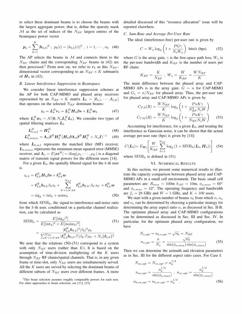
yields the antenna aperture size of n = 240 = na × ne =16 × 15, corresponding to La = 3.4” and Le = 3.2”. Theoptimum phased array and CAP-MIMO AP configurations, inthe aperture and beamspace domains, are shown in Fig. 4.The optimum phased array configuration consists of 12 sub-
(a) (b)
Fig. 4. Array configurations for nb = 144 and NRF =√nb = 12 RF
chains. (a) Optimal 12-aperture/12-beam phased array configuration. (b) CAP-MIMO configuration with 12 beamspace sectors, each sector consisting of 12beams and driven by one RF chain.
arrays each of size 4 × 5 and driven by one RF chain. TheCAP-MIMO configuration consists of 12 beamspace sectors,each with 12 beams and driven by an RF chain via a 1-to-12 switch. The switch dimension can be reduced by usingmulti-aperture or composite-feed CAP-MIMO configurationsas discussed in Sec. IV. For example, composite feeds covering2 high-resolution beams can be used to reduce the switchdimension from 12 to 6.
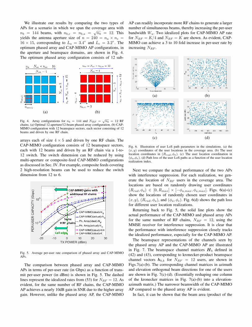
Fig. 5. Average per-user rate comparison of phased array and CAP-MIMOAPs.
The comparison between phased array and CAP-MIMOAPs in terms of per-user rate (in Gbps) as a function of trans-mit per-user power (in dBm) is shown in Fig. 5. The dashedlines represent the idealized rates from (53) for NRF = 12. Asevident, for the same number of RF chains, the CAP-MIMOAP achieves a nearly 10dB gain in SNR due to the higher arraygain. However, unlike the phased array AP, the CAP-MIMO
AP can readily incorporate more RF chains to generate a largernumber of simultaneous beams, thereby increasing the per-userbandwidth Wu. Two idealized plots for CAP-MIMO AP ratefor NRF = K/4 and NRF = K are shown. As evident, CAP-MIMO can achieve a 3 to 10 fold increase in per-user rate byincreasing NRF .
(a) (b)
(c) (d)
Fig. 6. Illustration of user LoS path parameters in the simulations. (a) the(x, y) coordinates of the user locations in the coverage area. (b) The userlocation coordinates in (Rrad, φa). (c) The user location coordination in(φa,φe). (d) Path loss of the user LoS paths as a function of the user locationrealization index.
Next we compare the actual performance of the two APswith interference suppression. For each realization, we gen-erate the location of NRF users in the coverage area. Thelocations are based on randomly drawing user coordinates(Rrad, φa) ∈ [0, Rmax] × [−φa,max, φa,max]. Figs. 6(a)-(c)show the locations of randomly chosen user coordinates in(x, y), (Rrad, φa), and (φa, φe). Fig. 6(d) shows the path lossfor different user location realizations.
Returning back to Fig. 5, the solid line plots show theactual performance of the CAP-MIMO and phased array APsfor the same number of RF chains, NRF = 12, using theMMSE receiver for interference suppression. It is clear thatthe performance with interference suppression closely tracksthe idealized performance, especially for the CAP-MIMO AP.
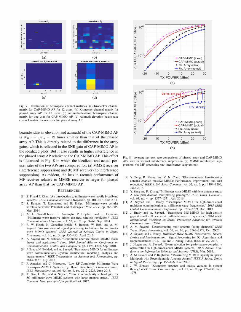
The beamspace representations of the channels seen bythe phased array AP and the CAP-MIMO AP are illustratedin Fig. 7. The beamspace channel matrices Hb defined in(42) and (43), corresponding to kronecker-product beamspacechannel vectors hb,k for NRF = 12 users, are shown inFigs.7(a)-(b). The corresponding channel matrices in azimuthand elevation orthogonal beam directions for one of the usersare shown in Fig. 7(c)-(d). (Essentially reshaping one columnof the kronecker matrices in Fig. 7(a)-(b) into a elevation-azimuth matrix.) The narrower beamwidth of the CAP-MIMOAP compared to the phased array AP is evident.
In fact, it can be shown that the beam area (product of the
(a) (b)
(c) (d)
Fig. 7. Illustration of beamspace channel matrices. (a) Kronecker channelmatrix for CAP-MIMO AP for 12 users. (b) Kronecker channel matrix forphased array AP for 12 users. (c) Azimuth-elevation beamspace channelmatrix for one user for CAP-MIMO AP. (d) Azimuth-elevation beamspacechannel matrix for one user for phased array AP.
beamdwidths in elevation and azimuth) of the CAP-MIMO APis NRF =
√nb = 12 times smaller than that of the phased
array AP. This is directly related to the difference in the arraygains, which is reflected in the SNR gain of CAP-MIMO AP inthe idealized plots. But it also results in higher interference inthe phased array AP relative to the CAP-MIMO AP. This effectis illustrated in Fig. 8 in which the idealized and actual per-user rates of the two APs are compared for: (a) MMSE receiver(interference suppression) and (b) MF receiver (no interferencesuppression). As evident, the loss in (actual) performance ofMF receiver relative to MMSE receiver is larger for phasedarray AP than that for CAP-MIMO AP.
REFERENCES
[1] Z. Pi and F. Khan, “An introduction to millmeter-wave mobile broadbandsystems,” IEEE Commununications Magazine, pp. 101–107, June 2011.
[2] S. Rangan, T. Rappaport, and E. Erkip, “Millimeter-wave cellularwireless networks: Potentials and challenges,” Proc. IEEE, pp. 366–385,Mar. 2014.
[3] A. L. Swindlehurst, E. Ayanoglu, P. Heydari, and F. Capolino,“Millimeter-wave massive mimo: the next wireless revolution?” IEEECommunications Magazine, vol. 52, no. 9, pp. 56–62, Sep. 2014.
[4] R. W. Heath, N. Gonzalez-Prelcic, S. Rangan, W. Roh, and A. M.Sayeed, “An overview of signal processing techniques for millimeterwave MIMO systems,” IEEE Journal of Selected Topics in SignalProcessing, vol. 10, no. 3, pp. 436–453, April 2016.
[5] A. Sayeed and N. Behdad, “Continuous aperture phased MIMO: Basictheory and applicatons,” Proc. 2010 Annual Allerton Conference onCommunications, Control and Computers, pp. 1196–1203, Sep. 2010.
[6] J. Brady, N. Behdad, and A. Sayeed, “Beamspace MIMO for millimeter-wave communications: System architecture, modeling, analysis andmeasurements,” IEEE Transactions on Antenna and Propagation, pp.3814–3827, July 2013.
[7] P. Amadori and C. Masouros, “Low RF-Complexity Millimeter-WaveBeamspace-MIMO Systems by Beam Selection,” Communications,IEEE Transactions on, vol. 63, no. 6, pp. 2212–2223, June 2015.
[8] X. Gao, L. Dai, and A. Sayeed, “Low RF-complexity technologies for5G millimeter-wave MIMO systems with large antenna arrays,,” IEEECommun. Mag. (accepted for publication), 2017.
(a)
(b)
Fig. 8. Average per-user rate comparison of phased array and CAP-MIMOAPs with or without interference suppression. (a) MMSE interference sup-pression. (b) MF processing (no interference suppression).
[9] Y. Zeng, R. Zhang, and Z. N. Chen, “Electromagnetic lens-focusingantenna enabled massive MIMO: Performance improvement and costreduction,” IEEE J. Sel. Areas Commun., vol. 32, no. 6, pp. 1194–1206,June 2016.
[10] Y. Zeng and R. Zhang, “Millimeter wave MIMO with lens antenna array:A new path division multiplexing paradigm,” IEEE Trans. Commun.,vol. 64, no. 4, pp. 1557–1571, Apr. 2016.
[11] A. Sayeed and J. Brady, “Beamspace MIMO for high-dimensionalmultiuser communication at millimeter-wave frequencies,” 2013 IEEEGlobal Communications Conference, pp. 3785–3789, Dec. 2013.
[12] J. Brady and A. Sayeed, “Beamspace MU-MIMO for high-densitygigabit small cell access at millimeter-wave frequencies,” 2014 IEEEInternational Workshop on Signal Processing Advances for WirelessCommunications, 2014.
[13] A. M. Sayeed, “Deconstructing multi-antenna fading channels,” IEEETrans. Signal Processing, vol. 50, no. 10, pp. 2563–2579, Oct. 2002.
[14] A. Sayeed and J. Brady, Millimeter-Wave MIMO Transceivers: Theory,Design and Implementation. Signal Processing for 5G: Algorithms andImplementations (F.-L. Luo and J. Zhang, Eds.), IEEE-Wiley, 2016.
[15] J. Hogan and A. Sayeed, “Beam selection for performance-complexityoptimization in high-dimensional MIMO systems,” 50-th Annual Con-ference on Information Sciences and Systems (CISS), Mar. 2016.
[16] A. M. Sayeed and V. Raghavan, “Maximizing MIMO Capacity in SparseMultipath with Reconfigurable Antenna Arrays,” IEEE J. Select. Topicsin Signal Processing, pp. 156–166, June 2007.
[17] J. W. Brewer, “Kronecker products and matrix calculus in systemtheory,” IEEE Trans. Circ. and Syst., vol. 25, no. 9, pp. 772–781, Sep.1978.