Embed Size (px)
Citation preview
Multi-Angle Color
Measurement
and
Correlation to Visual
1
Kendall Scott
BYK User Meeting
June 11-12, 2013
2
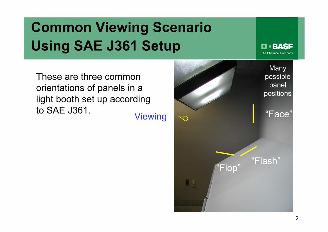
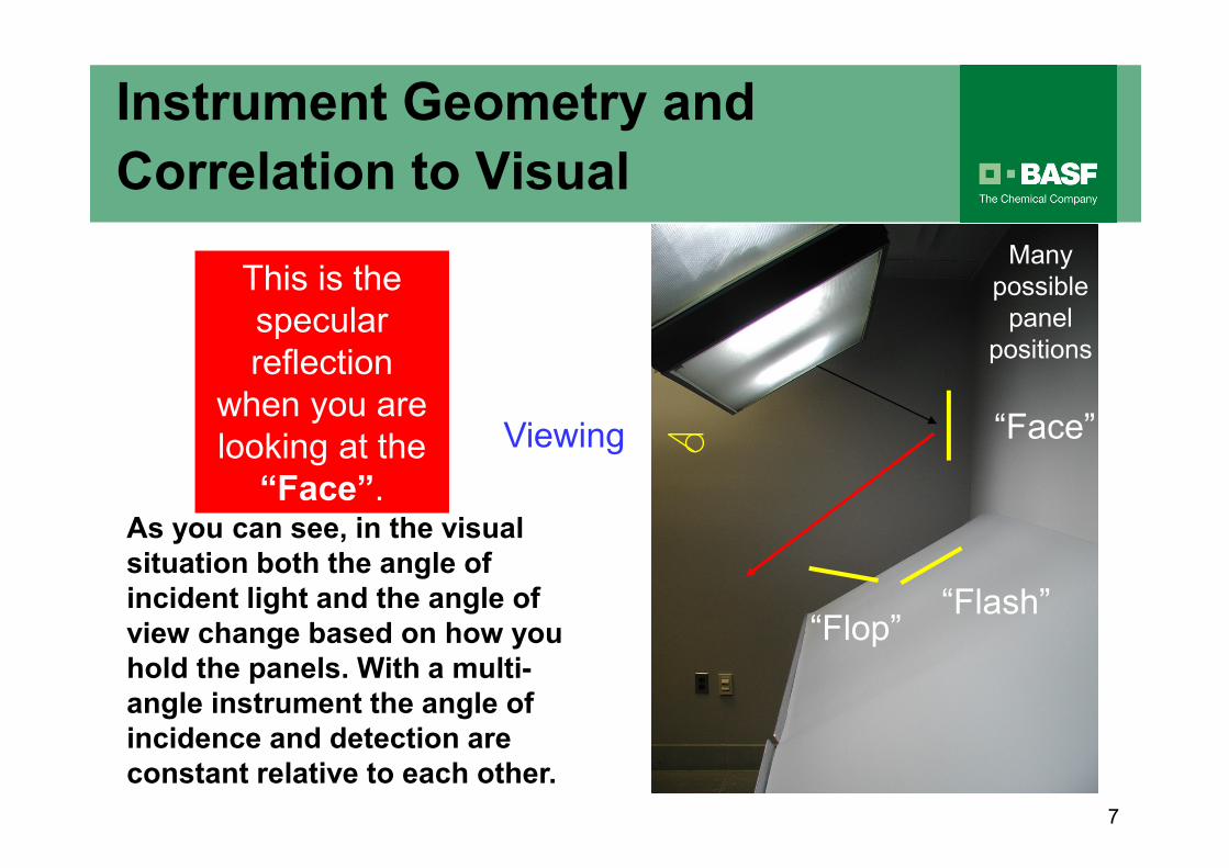
Viewing
Many
possible
panel
positions
“Face”
“Flash”“Flop”
These are three common
orientations of panels in a
light booth set up according
to SAE J361.
Common Viewing Scenario
Using SAE J361 Setup

3
Standard Color Measurement
Geometries
-15o
4
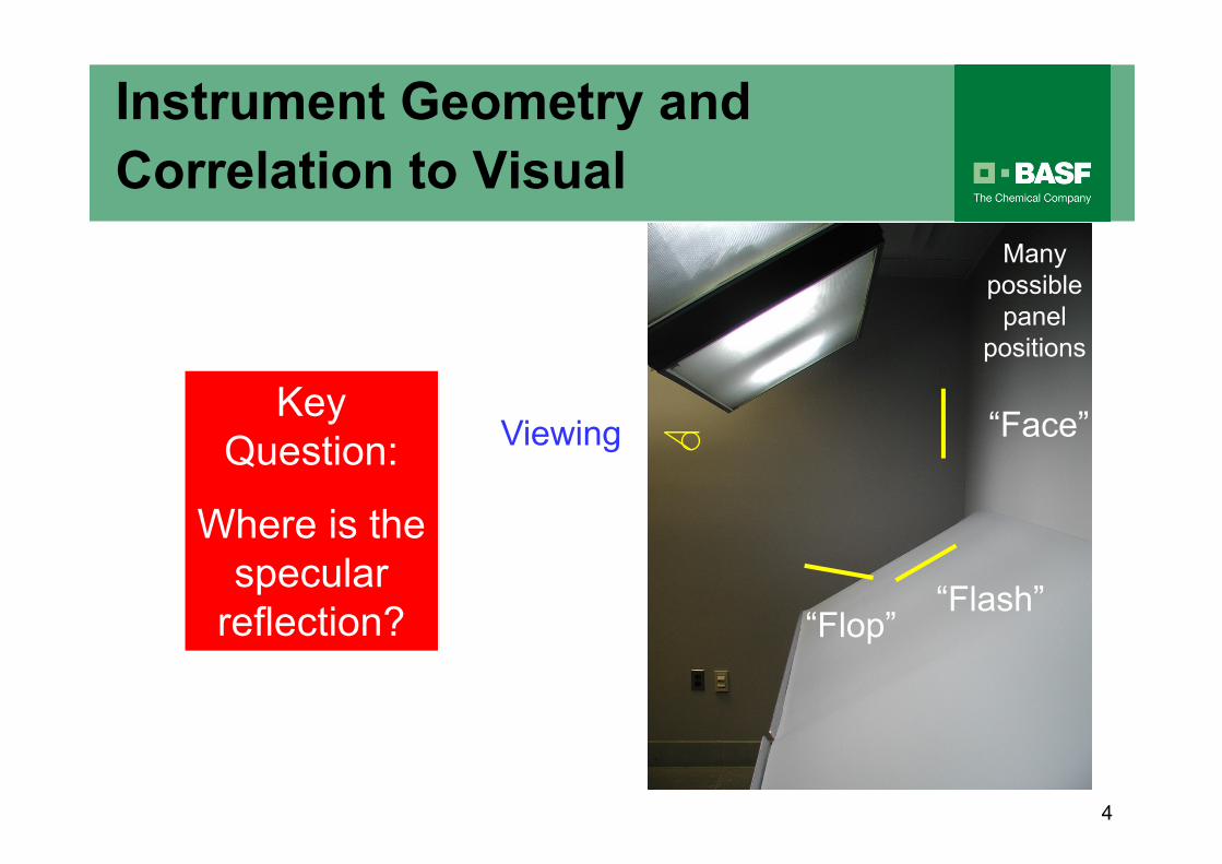
Viewing
Many
possible
panel
positions
“Face”
“Flash”“Flop”
Key
Question:
Where is the
specular
reflection?
Instrument Geometry and
Correlation to Visual

5
Viewing
Many
possible
panel
positions
“Face”
“Flash”“Flop”
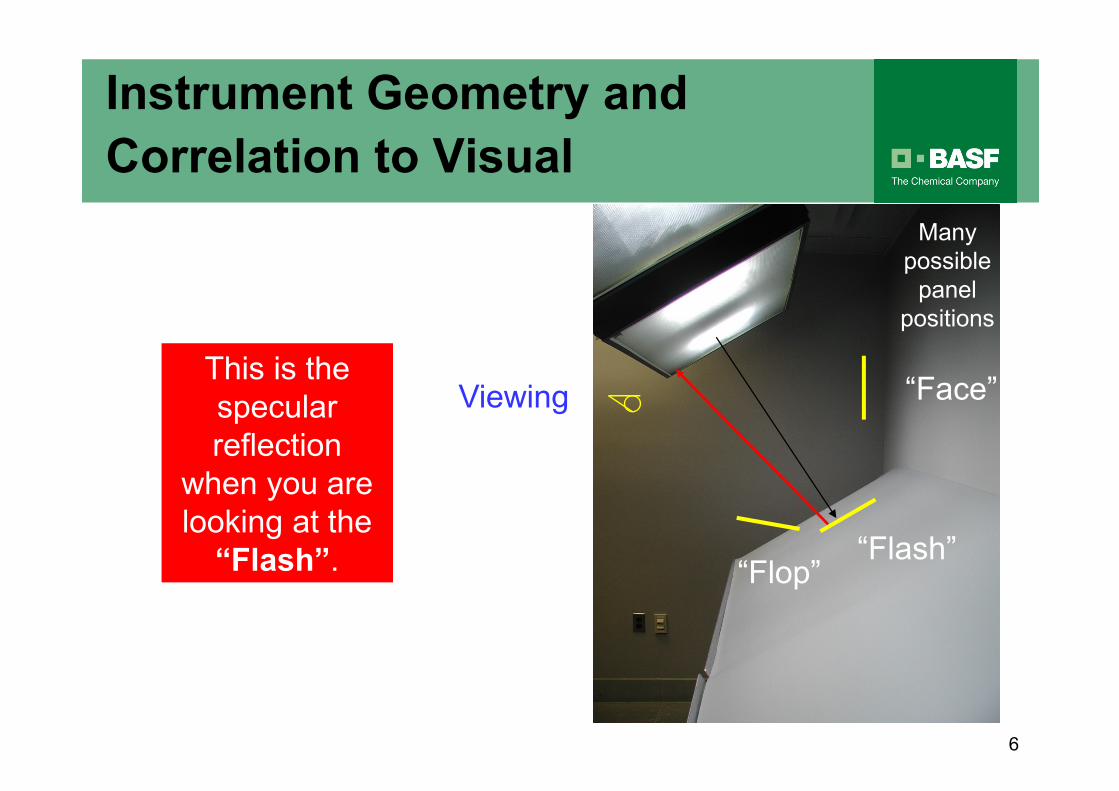
This is the
specular
reflection
when you are
looking at the
“Flop”.
Instrument Geometry and
Correlation to Visual
This is the
specular
reflection
when you are
looking at the
“Flop”.
6
Viewing
Many
possible
panel
positions
“Face”
“Flash”“Flop”
This is the
specular
reflection
when you are
looking at the
“Flash”.
Instrument Geometry and
Correlation to Visual
7
Viewing
Many
possible
panel
positions
“Face”
“Flash”“Flop”
This is the
specular
reflection
when you are
looking at the
“Face”.As you can see, in the visual
situation both the angle of
incident light and the angle of
view change based on how you
hold the panels. With a multi-
angle instrument the angle of
incidence and detection are
constant relative to each other.
Instrument Geometry and
Correlation to Visual
8
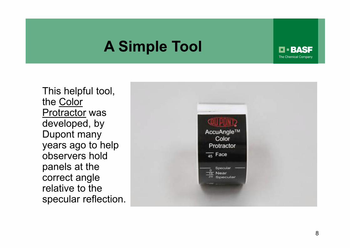
This helpful tool, the Color Protractor was developed, by Dupont many years ago to help observers hold panels at the correct angle relative to the specular reflection.
A Simple Tool

9
View a pair of panels in the light booth with a known, large difference in color travel.
For example, look at a light metallic with and without a significant hit of white pigment dispersion.
How would you expect this pair to look in the light booth? What would the “Face”, “Flash”, and “Flop” look like?
How would you expect this pair to lookon a color difference plot?
Another Simple Tool Developed for
Tinters with Knowledge of Pigments

10
How would you expect this pair
to look in a light booth?
“Face”
“Flash”
“Flop”
Left = As Is
Right = Addition of White
Light metallic with and without
white dispersion added to it
11
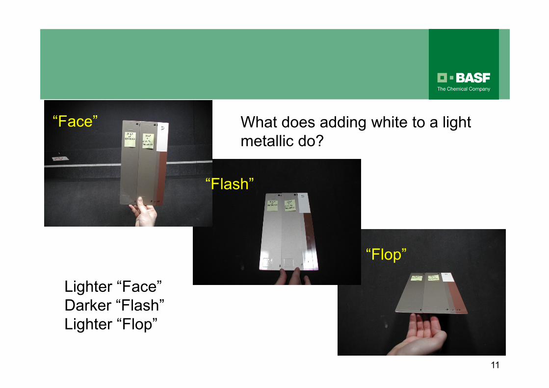
Lighter “Face”
Darker “Flash”
Lighter “Flop”
What does adding white to a light
metallic do?
“Face”
“Flash”
“Flop”
12
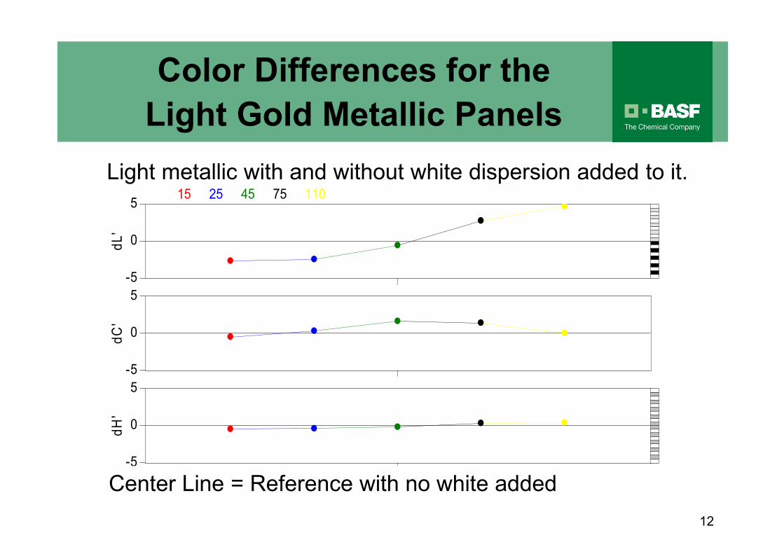
Color Differences for the
Light Gold Metallic Panelsd
L'
dC
'd
H'
0
-5
5
0
-5
5
0
-5
5
15 25 45 75 110
2
� �
�
�
�
��
� ��
� � � � �
Light metallic with and without white dispersion added to it.
Center Line = Reference with no white added
13
dL
'd
C'
dH
'
0
-5
5
0
-5
5
0
-5
5
15 25 45 75 110
2
� �
�
�
�
��
� ��
� � � � �
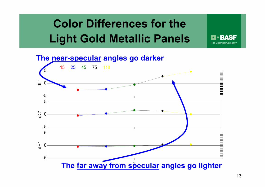
The near-specular angles go darker
The far away from specular angles go lighter
Color Differences for the
Light Gold Metallic Panels
14
Viewing
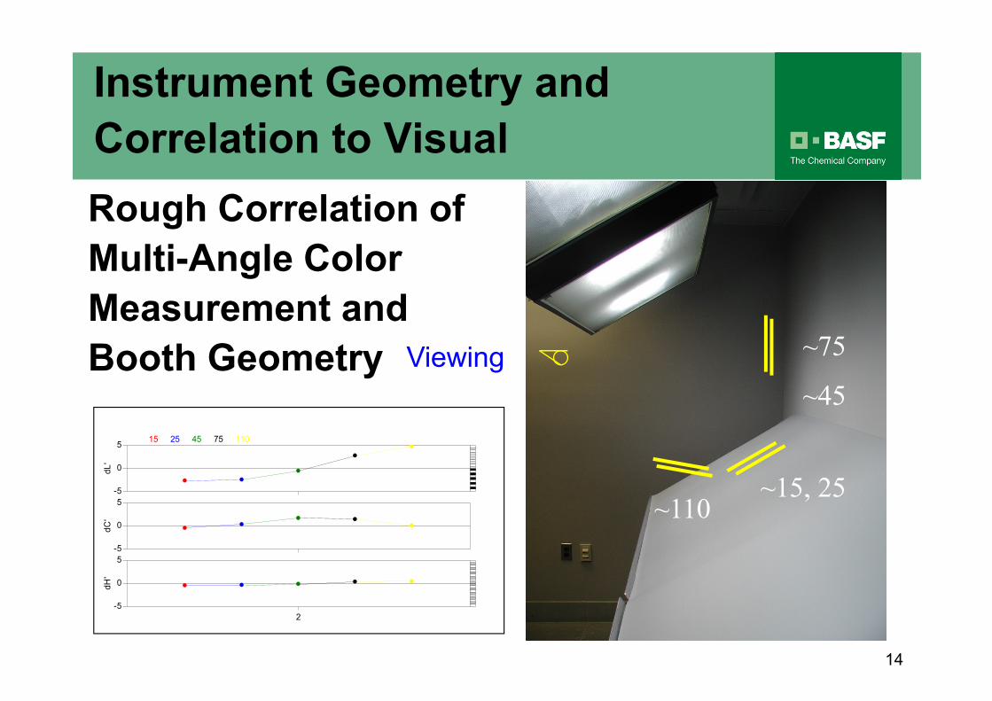
Rough Correlation of
Multi-Angle Color
Measurement and
Booth Geometry
dL
'd
C'
dH
'
0
-5
5
0
-5
5
0
-5
5
15 25 45 75 110
2
� �
�
�
�
��
� ��
� � � � �
~75
~15, 25~110
~45
Instrument Geometry and
Correlation to Visual
15
Viewing
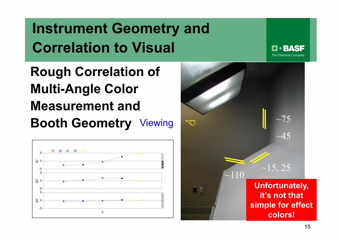
Rough Correlation of
Multi-Angle Color
Measurement and
Booth Geometry
dL
'd
C'
dH
'
0
-5
5
0
-5
5
0
-5
5
15 25 45 75 110
2
� �
�
�
�
��
� ��
� � � � �
~75
~15, 25~110
~45
Unfortunately,
it’s not that
simple for effect
colors!
Instrument Geometry and
Correlation to Visual
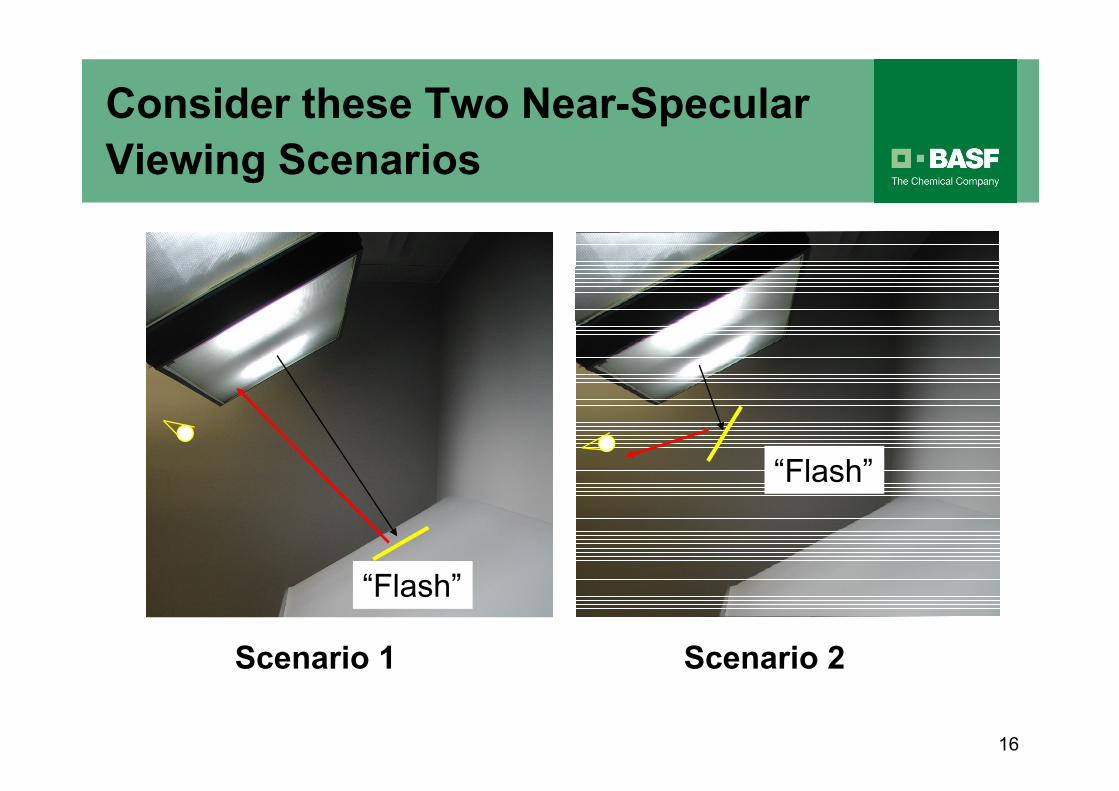
Consider these Two Near-Specular
Viewing Scenarios
“Flash”
Scenario 1
16
Scenario 2
“Flash”
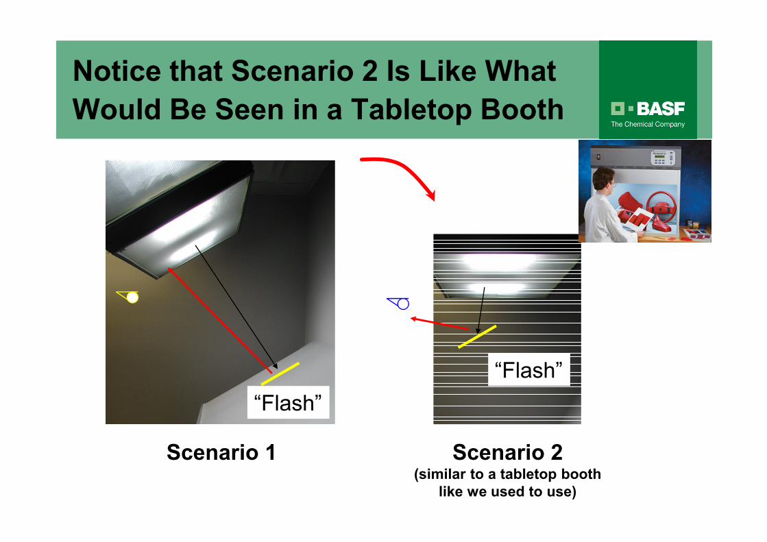
Notice that Scenario 2 Is Like What
Would Be Seen in a Tabletop Booth
“Flash”
Scenario 1 Scenario 2
“Flash”
Scenario 2(similar to a tabletop booth
like we used to use)
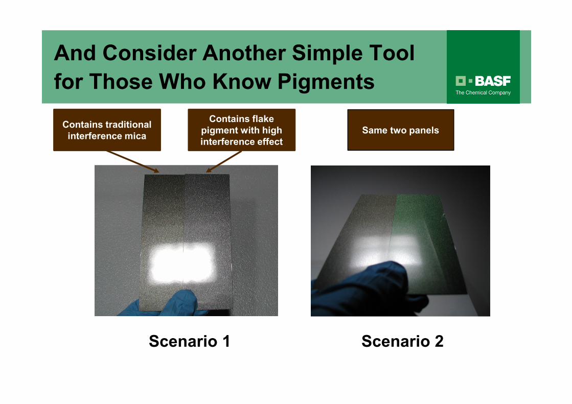
Scenario 1 Scenario 2
And Consider Another Simple Tool
for Those Who Know Pigments
Contains traditional
interference mica
Contains flake
pigment with high
interference effect
Same two panels
1919
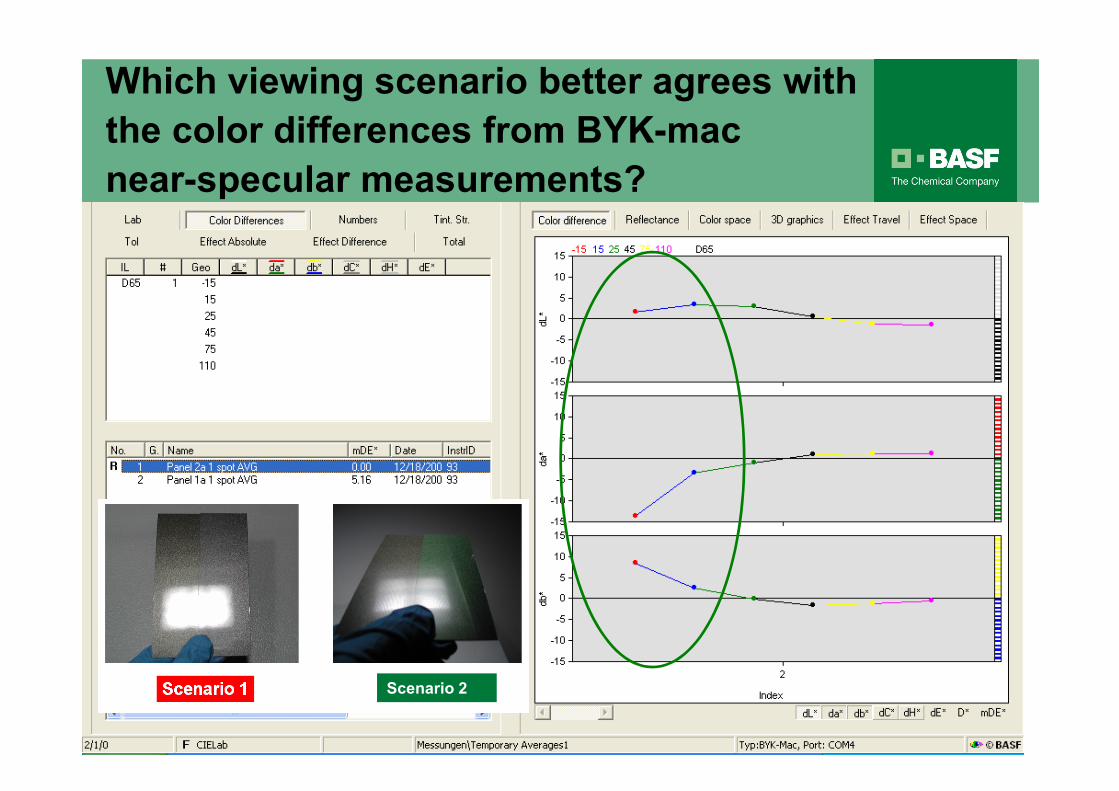
Which viewing scenario better agrees with
the color differences from BYK-mac
near-specular measurements?
Scenario 2
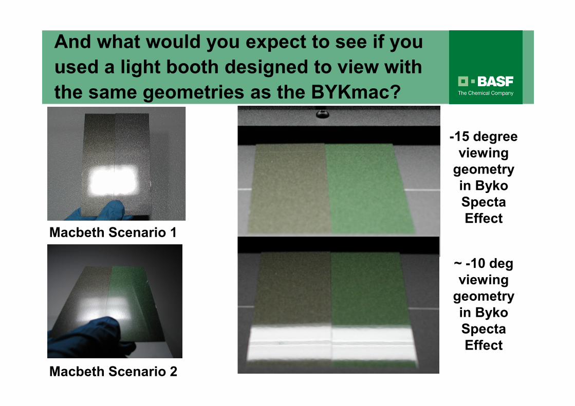
And what would you expect to see if you
used a light booth designed to view with
the same geometries as the BYKmac?
Macbeth Scenario 1
Macbeth Scenario 2
-15 degree
viewing
geometry
in Byko
Specta
Effect
~ -10 deg
viewing
geometry
in Byko
Specta
Effect
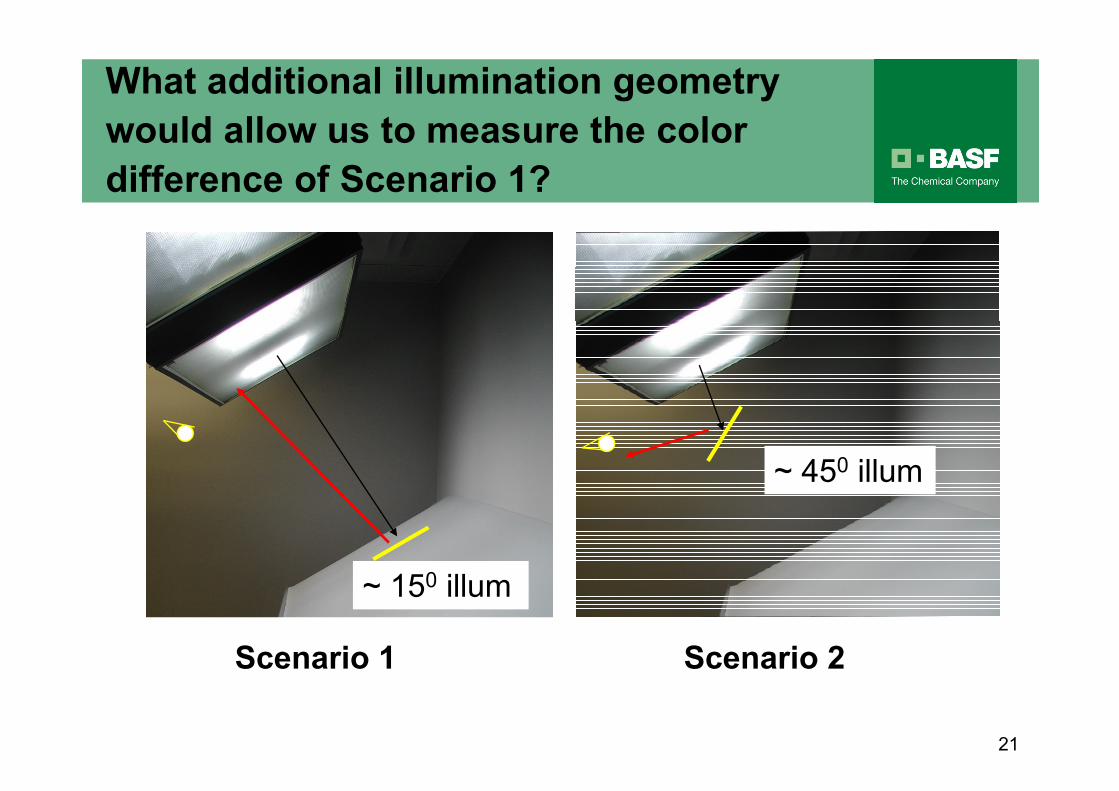
~ 150 illum
Scenario 1
21
Scenario 2
~ 450 illum
What additional illumination geometry
would allow us to measure the color
difference of Scenario 1?
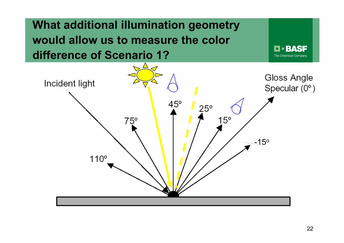
-15o
22
What additional illumination geometry
would allow us to measure the color
difference of Scenario 1?
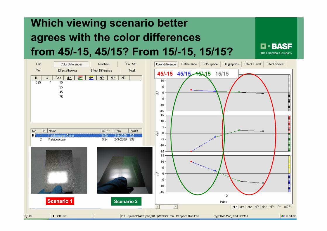
45/-15 45/15 15/-15 15/15
Which viewing scenario better
agrees with the color differences
from 45/-15, 45/15? From 15/-15, 15/15?
Scenario 2
Summary Thoughts
• Many things affect the correlation between multi-angle
color measurements and visual assessments, not the least
of which is instrument and viewing geometry.
• Realize that when you move panels in a traditional light
booth, both the angle of incidence and angle of detection
change simultaneously. With the BYKmac the angle of
incidence is fixed relative to the panel.
• The Byko Spectra Effect light booth has the same fixed
geometries as the BYKmac, and can be expected to agree
better with the measurements of the BYKmac than a
traditional light booth, especially if any of the color is
produced by light interference effects.

Summary Thoughts
• The addition of a second angle of illumination at 15
degrees with 15 and -15 degree viewing, together with the
existing geometries, would provide better correlation with
how we traditionally view panels under the booth setup of
SAE J361.