Embed Size (px)
Citation preview

Only the Really Big Ideas can take ConstantChange in their Stride
OriginalM. E. Müller™
Straight Stem
Surgical Technique

Disclaimer This document is intended exclusively for experts in the field, i.e. physicians in particular, and is expressly not for the information of laypersons.The information on the products and/or procedures contained in this document is of a general nature and does notrepresent medical advice or recommendations. Since this information does not constitute any diagnostic or therapeuticstatement with regard to any individual medical case, individual examination and advising of the respective patientare absolutely necessary and are not replaced by this document in whole or in part.The information contained in this document was gathered and compiled by medical experts and qualified Zimmeremployees to the best of their knowledge. The greatest care was taken to ensure the accuracy and ease of understanding of the information used and presented. Zimmer does not assume any liability, however, for the up-to-dateness, accuracy, completeness or quality of the information and excludes any liability for tangible or intangible losses that maybe caused by the use of this information.In the event that this document could be construed as an offer at any time, such offer shall not be binding in any eventand shall require subsequent confirmation in writing.

3Original M. E. Müller™ Straight Stem
Surgical TechniqueOriginal M. E. MüllerStraight Stem
Contents
Introduction 4
Pre-Operative Planning 5
Planning Steps 6
Surgical Techniques 9
Case Studies 14
Ordering Information 16
Implants 16
Instruments 18
Materials 21

4 Original M. E. Müller™ Straight Stem
The history of the Original M.E. MüllerStraight Stem is an example of consistentimplementation of a fundamentalbiomechanical principle in practice.
Introduction – Original M.E. Müller Straight Stem
The Müller Straight Stem locks itselfaccording to the three-point principle.The straight, conically tapering shapeof the stem allows the implant to beplaced in the femur in a neutral axis.Due to its wedge shape, the stem findsthe central axis automatically, thusexcluding a varus or valgus position.
With the Original M.E. Müller StraightStem, Professor Müller has developed a coherent prosthetic system, which isa constituent part of his orthopedicphilosophy. The fundamental principlesare the well thought-out prosthesiscomponents, the simple pre-operativeplanning, and the reproducible surgicaltechnique, together with the documen-tation/evaluation of the hip operations. Additional elements are precise and long-lasting instruments and theunproblematic removability of theimplants.The excellent clinical results of the Original M.E. Müller Straight Stem haveproved the biomechanical conceptbehind this implant since 1977. In 2003, the millionth Original M.E.Müller Straight Stem was implanted in Munich, Germany.

5Original M. E. Müller™ Straight Stem
The graphic planning of the hip replace-ment implantation forces the orthopedicsurgeon to carry out detailed analysisof the X ray image, and to anticipate theoperation in detail. “This (correct planning – author) provides important information aboutthe choice of the correct model and the correct size of the prosthesis, thedepth of the acetabulum preparation,the height of the neck resection, and the positioning and alignment ofthe pelvic and femoral components.It allows fast and systematic executionof the operation and thus minimizesthe risk of complications for thepatient.” (Müller, M.E., Jaberg, H., 1989)
Pre-Operative Planning – Purpose and Aids
Besides the obvious advantages ofanticipating intraoperative difficulties,the pre-operative planning serves tocorrect and avoid differences in leglength.As a part of quality assurance, pre-operative planning supports the workof the surgical team, and serves asa method of self-monitoring for the surgeon.
Planning template OriginalM. E. Müller Straight Stem, standard and lateral, enlargement factor 1.15 : 1,Lit. No. 06.01114.000
Original M.E. Müller™ Straight StemCemented, Cone 12/14, CCD-Angle 135°The reference number must correspond to that of the prosthesis to be implanted. © All rights reserved, Zimmer GmbH, CH-8404 Winterthur, Switzerland, 1/2005, Lit.No. 06.01114.000x-WL 7 611814 640011
0 cm
5 cm
10 cm
15 cm
5 cm 10 cm
Magnification 1.15 :1
Resection Area
T
rightleft
Straight StemStandard
Original M.E. Müller™ Straight StemCemented, Cone 12/14, CCD-Angle 135°The reference number must correspond to that of the prosthesis to be implanted. © All rights reserved, Zimmer GmbH, CH-8404 Winterthur, Switzerland, 1/2005, Lit.No. 06.01114.000x-WL 7 611814 640011
0 cm
5 cm
10 cm
15 cm
5 cm 10 cm
Magnification 1.15 :1
Resection Area
T
right
Straight Stem
Lateral
left

6 Original M. E. Müller™ Straight Stem
The planning sketch provides the necessary information with regard tomodel and size of the prosthesiscomponents, as well as with regard tothe position of the center of rotation.Graphic planning with the Original M.E. Müller Straight Stem starts withthe determination of the offset, i.e. withthe question of whether the standard or the lateral version is indicated. In thesimple case of unilateral coxarthrosis,
Planning Steps
Original M.E. Müller™ Straight Stem
Cemented, Cone 12/14, CCD-Angle 135°
The reference number must correspond to that of the prosthesis to be
implanted. © All rights reserved, Zimmer GmbH, CH-8404 Winterthur,
Switzerland, 1/2005, Lit.No. 06.01114.000x-WL7611814640011
0 cm
5 cm
10 cm
15 cm
5 cm10 cm Magnification
1.15 :1
Resection Area
T
rightleft
Original M.E. Müller™ Straight StemCemented, Cone 12/14, CCD-Angle 135°The reference number must correspond to that of the prosthesis to be implanted. © All rights reserved, Zimmer GmbH, CH-8404 Winterthur, Switzerland, 1/2005, Lit.No. 06.01114.000x-WL 7 611814 640011
0 cm
5 cm
10 cm
15 cm
5 cm10 cm
Magnification 1.15 :1
T
rightleft
this can be answered on the healthyopposite side (reference side). One alsoorientates oneself on this side withregard to the position of the center ofrotation that is to be reconstructed with the hip prosthesis.When fitting the Original M.E. MüllerStraight Stem, attention must be paidto a centered position and an indicatedcortex contact in the medullary cavity.
1. Standard or Lateral Version?In our example, the template of the lateral version of the Original M.E.Müller Straight Stem is placed over thehealthy hip in such a way that on the one hand it is concentric in relationto the center of rotation, and on theother hand it has its axis parallel to thelongitudinal axis of the femur. If themedial contour of the prosthesis stem ismore than 6 mm lateral of the medialcortex (as in our example), the standardversion (blue) should be selected.In this planning step, one also notes theheight of the head center in relation tothe tip of the trochanter, and transfersit to the side to be operated on, in orderto be able to realize the same leglengths on both sides.
2. Which Stem Size?The selected template is now positionedover the femur that is to be operatedon, such that the prosthesis stem comesto rest centered in the medullarycavity and at the same time the T-linecomes to rest at the same height ason the reference side. The stem size that will probably fit willbe the one, which roughly comesinto contact with the cortex of the shaft(or the next smaller one).

7Original M. E. Müller™ Straight Stem
3. Drawing the ProstheticStem and the Femur ContoursThe correct size of prosthetic stem and the contours of the femur are nowtransferred onto a sheet of tracingpaper, which is placed over the templateand X ray image. Care must be takenhere that the sheet with the drawing is placed parallel to the template, in order to maintain a physiological hipjoint position on the planning sketch.
4. Which Cup and which Cup Size?The template for the selected cup isplaced over the acetabulum in such away that the center of the cup corres-ponds with the anatomical center of theacetabulum, the cup contour comesinto direct contact with the subchondralbone cranially, and the desired incli-nation is achieved. With the templatefor the Straight Stem prosthesis, an acetabular inclination of 40° is shownwhen the template is placed parallel tothe longitudinal axis of the pelvis.
5. Drawing the Acetabulum and the Pelvis ContoursThe planning sketch which has beenstarted is now placed over the templateand the X ray image in such a waythat the center of the head (sketch) andthe center of the acetabulum (template)correspond, and the tracing paper sheet lies parallel to the template. Thecontours of the correct cup and ofthe hemi-pelvis are then transferred tothe planning sketch.
Original M.E. Müller™ Straight StemCemented, Cone 12/14, CCD-Angle 135°The reference number must correspond to that of the prosthesis to be implanted. © All rights reserved, Zimmer GmbH, CH-8404 Winterthur, Switzerland, 1/2005, Lit.No. 06.01114.000x-WL 7 611814 640011
0 cm
5 cm
10 cm
15 cm
5 cm10 cm
Magnification 1.15 :1
T
rightleft
Original M.E. Müller™ Straight StemCemented, Cone 12/14, CCD-Angle 135°The reference number must correspond to that of the prosthesis to be implanted. © All rights reserved, Zimmer GmbH, CH-8404 Winterthur, Switzerland, 1/2005, Lit.No. 06.01114.000x-WL 7 611814 640011
0 cm
5 cm
10 cm
15 cm
5 cm 10 cm
Magnification 1.15 :1
T
rightleft

8 Original M. E. Müller™ Straight Stem
6. Final DrawingFinally, all the necessary informationabout the prosthetic components(type, size, insert) is entered, and thedistances to the greater and lesser trochanter (T-line – trochanter tip, R-line– trochanter base, taper end – trochan-ter base and taper end – resectionlevel) are measured and noted. The planning sketch is completed withpatient identification and the date of the operation, as well as any detailsof additional measures.
Straight Stem Standard12.5 (10)Pat: P.Q. 67yOP: 24.3.03
Further literature
Gill TJ, Sledge JB, Müller ME: Total hip arthroplasty with use of an acetabular reinforcement ring in patients who have congenitaldysplasia of the hip. J Bone Joint Surg Am 80: 969, 1998
Lützner J, Ochsner PE: Langzeitergebnisse mit der Original M.E. MüllerGeradschaftsprothese aus CoNiCrMo-Schmiede-legierung (Protasul-10).Orthopädische Praxis 7: 36, 2000
Müller ME, Jaberg H: Total hip reconstruction. In Evarts CM (ed): Surgery of the musculoskeletal system. 2nd ed. Churchill Livingstone, New York, 1989
Ochsner PE (Hrsg):Die Hüfttotalprothese. Implantationstechnikund lokale Komplikationen. Springer, Berlin, 2003

9Original M. E. Müller™ Straight Stem
Surgical Technique
Preparation of the Medullary CanalThe Original Müller Straight Stem canbe implanted via all surgical approacheswith the patient lying on the side or on the back. Illustrated below are theindividual surgical steps for the lateral approach with the patient lyingon his or her back. All technicaldetails can, however, be transferredaccordingly to other approach routes.
1. The distance between the lesser trochanter and the resection level ismeasured. If necessary, perform further resection to conform with thepre-operative planning.
2. The medullary cavity is opened with the Lexer chisel and the right-angled gouge, maintaining an antetor-sion of 10°–15°, sufficiently dorso-laterally on account of the recurvationof the proximal femur end.
3. The medullary cavity is probed in the direction of the knee, using a longcurette, in order to establish the raspdirection. In the event of difficulty, the awl can be used to assist here.

10 Original M. E. Müller™ Straight Stem
4. The medullary cavity is widened withshaped rasps of increasing size, startingwith the smallest size. Depending onwhether a Straight Stem standard or aStraight Stem lateral was envisaged in the pre-operative planning, the workis carried out with rasps in standard or lateral versions.
The modular rasp simultaneously servesas a trial prosthesis.
5. After removal of the modular handle,the distance from the taper end to the resection level is measured, in orderto determine the correct leg length.
6. The test head is mounted for trialreduction. Possible check of the trochanter distance T (distance from the trochanter tip to the height ofthe head center) with Kirschner wire.
Check the range of movement, tendencyto dislocation (internal rotation with flexion, external rotation with extension,adduction) and the leg length.
7. On the Straight Stem prosthesis thatis to be implanted, with the intro-ducing rod for medullary plug, a measu-re is now taken for the position ofthe medullary plug, measured from theprosthetic medial rim indicating thelevel of resection. The plug should beplaced 0.5–1 cm distally of the pros-thesis tip.

11Original M. E. Müller™ Straight Stem
8. After the trial rasp has been extracted,the size of the medullary plug is deter-mined with the aid of the measure cone.
9. The Stühmer/Weber or other medullary plug is placed.Medullary plugs of autologous bonehave the advantage that they can beabsorbed.
10. a The cement is introduced in antegrade fashion, using a drain and a silicon disk for compression.
10. b Alternatively, the cement is pressedin in retrograde manner. This procedurerequires neither a compression disk nora drain.
11. In the case of the antegrade techni-que, as soon as the medullary spacehas been filled with cement, the drainand compression disk are removed.
a b

12 Original M. E. Müller™ Straight Stem
12. The stem is introduced using the impactor, with dosed pressing in ofthe stem until the specified distancebetween the cone edge and the resec-tion level has been reached.
13. After the cement has hardened completely, and the taper has beencarefully rinsed, the ball head ismounted. If necessary, a trial reductionis carried out beforehand with the trial head. The head is mounted with a rotatory movement.
14. Locking of the head by means ofa light hammer blow on the reductionlever.
15. The joint components are reduced,and the function check repeated. Closure of the wound, Redon drainage.

13Original M. E. Müller™ Straight Stem
Anchoring the Müller Straight StemThe Straight Stem prosthesis is self-centering and locks itself thanksto its 6° taper (AP view) in the femur (in case of a valgus hip, it locks atthree points in the frontal plane: medi-ally on the calcar and at the prosthesistip, and laterally in the metaphysis). Additional anchorage is achievedthrough the cement mantle, which, dueto the flat cross-section of the stem,divides the cement mantle into a ventraland a dorsal cement half.

14 Original M. E. Müller™ Straight Stem
Male Patient, Date of Birth: 16 September 1960
Age at Time of Operation: 25 years
Case Studies
Postoperative After 18 years
Preoperative
Indication: Femur head necrosisfollowing fracture of the femur neck.
Implants: Original Müller Straight Stem,lateral, CoCr, size 12.5. Müller PE cup,cemented.
Walking ability: good – over 60 minuteswithout crutches, free of pain.
Flexion: > 90°, abduction/adduction 30-0-40, internal rotation/external rotation 20-0-30. Free single-leg stance, no limping.

15Original M. E. Müller™ Straight Stem
Female Patient, Date of Birth: 11 March 1922
Age at Time of Operation:62 years
Postoperative After 16 years
Preoperative
Indication: Dysplasia coxarthrosis
Implants: Original Müller Straight Stem,standard, CoCr, size 12.5. Müller PEcup, cemented.
Walking ability: good – up to 30 minuteswithout crutches, free of pain.
Flexion: > 90°, abduction/adduction 30-0-20, internal rotation/external rotation 10-0-30. Slight limp.

16 Original M. E. Müller™ Straight Stem
Implants – Original M. E. Müller™ Straight Stem
Müller™ Straight Stem, lateral
Protasul® 10CementedM.E. Müller™
Size in mm REF
7.5 12.00.39-0758.75 05.95001.065
10.0 12.00.39-10011.25 12.00.39-11212.5 12.00.39-12513.75 12.00.39-13715.0 12.00.39-15016.25 12.00.39-16217.5 12.00.39-175
Müller™ Straight Stem, standard
Protasul® 10CementedM.E. Müller™
Size in mm REF
7.5 12.00.29-0758.75 05.95001.064
10.0 12.00.29-10011.25 12.00.29-11212.5 12.00.29-12513.75 12.00.29-13715.0 12.00.29-15016.25 12.00.29-16217.5 12.00.29-175
STERILE RSTERILE R
Müller™ Straight Stem, lateral
Protasul® 30CementedM.E. Müller™
Size in mm REF
7.5 35.00.39-0758.75 05.95001.067
10.0 35.00.39-10011.25 35.00.39-11212.5 35.00.39-12513.75 35.00.39-13715.0 35.00.39-15016.25 35.00.39-16217.5 35.00.39-175
STERILE R
Müller™ Straight Stem, standard
Protasul® 30CementedM.E. Müller™
Size in mm REF
7.5 35.00.29-0758.75 05.95001.066
10.0 35.00.29-10011.25 35.00.29-11212.5 35.00.29-12513.75 35.00.29-13715.0 35.00.29-15016.25 35.00.29-16217.5 35.00.29-175
STERILE R

17Original M. E. Müller™ Straight Stem
Müller™ Straight Stem, lateral, ∅ 28 mm
Protasul® 30CementedM.E. Müller™
Size in mm REF
7.5 35.28.39-07510.0 35.28.39-10011.25 35.28.39-11212.5 35.28.39-12513.75 35.28.39-13715.0 35.28.39-15017.5 35.28.39-175
Müller™ Straight Stem, standard, ∅ 28 mm
Protasul® 30CementedM.E. Müller™
Size in mm REF
7.5 35.28.29-07510.0 35.28.29-10011.25 35.28.29-11212.5 35.28.29-12513.75 35.28.29-13715.0 35.28.29-15017.5 35.28.29-175
STERILE R STERILE R
CDH stem, ∅ 22 mm
Protasul® 30CementedM.E. Müller™
Size in mm REF
5.0 30.22.69-0507.5 30.22.69-075
10.0 30.22.69-10012.5 30.22.69-125
The special instruments forimplantation of the CDH stem(monobloc rasps and testprostheses) are availableunder REF 99.41.00-00.
STERILE R

18 Original M. E. Müller™ Straight Stem
Instruments – Original M. E. Müller™ Straight Stem
Tray, Müller™ Straight Stem (complete)
REF
01.00245.622
Insert for tray, Müller™ Straight Stem(empty)
REF
01.00245.624
AwlREF
75.05.31
Double-curved gougeSize REF
9 mm 75.09.15
Handle with quick couplingREF
75.00.25
Curette, mediumSize REF
15 mm 75.13.33
All Instruments not sterile
Tray, Müller™ Straight Stem (empty)
REF
01.00245.623
Tray lidREF
01.00029.031
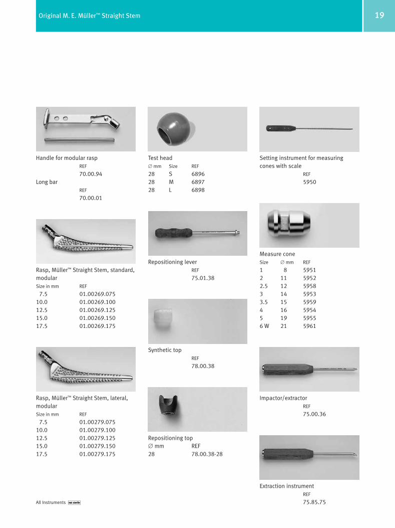
19Original M. E. Müller™ Straight Stem
Handle for modular raspREF
70.00.94Long bar
REF
70.00.01
Rasp, Müller™ Straight Stem, standard,modularSize in mm REF
7.5 01.00269.07510.0 01.00269.10012.5 01.00269.12515.0 01.00269.15017.5 01.00269.175
Repositioning leverREF
75.01.38
Test head∅ mm Size REF
28 S 689628 M 689728 L 6898
Rasp, Müller™ Straight Stem, lateral,modularSize in mm REF
7.5 01.00279.07510.0 01.00279.10012.5 01.00279.12515.0 01.00279.15017.5 01.00279.175
Synthetic topREF
78.00.38
Repositioning top∅ mm REF28 78.00.38-28
Impactor/extractorREF
75.00.36
Extraction instrumentREF
75.85.75
Setting instrument for measuringcones with scale
REF
5950
Measure coneSize ∅ mm REF
1 8 59512 11 59522.5 12 59583 14 59533.5 15 59594 16 59545 19 59556 W 21 5961
All Instruments not sterile

20 Original M. E. Müller™ Straight Stem
Test prostheses, Müller™ StraightStem, standardSize in mm REF
7.5 53.00.25-0758.75 53.00.25-087
10.0 53.00.25-10011.25 53.00.25-11212.5 53.00.25-12513.75 53.00.25-13715.0 53.00.25-15016.25 53.00.25-16217.5 53.00.25-175
Rasp, Müller™ Straight Stem, standard,modularSize in mm REF
8.75 05.00269.06911.25 01.00269.11213.75 01.00269.13716.25 01.00269.162
Rasp, Müller™ Straight Stem, lateral,modularSize in mm REF
8.75 05.95001.06911.25 01.00279.11213.75 01.00279.13716.25 01.00279.162
Test prostheses, Müller™ StraightStem, lateralSize in mm REF
7.5 53.00.35-0758.75 53.00.35-087
10.0 53.00.35-10011.25 53.00.35-11212.5 53.00.35-12513.75 53.00.35-13715.0 53.00.35-15016.25 53.00.35-16217.5 53.00.35-175
Test head∅ mm Size REF
28 XL 01.01519.808
32 S 683632 M 683732 L 683832 XL 01.01519.208
36 S 01.01519.63536 M 01.01519.63636 L 01.01519.63736 XL 01.01519.638
Repositioning top∅ mm REF
32 78.00.38-3236 78.00.38-36
Measure coneSize ∅ mm REF
7 W 24 5962
On Request

21Original M. E. Müller™ Straight Stem
CoNi35Cr20Mo10 alloy
Structure– Fine-grained austenitic base matrix
Properties– High mechanical strength values
in medium-hard and hard state– Can be welded to other Co alloys– Not suitable as articulation partner
with UHMWPE– High nickel content (allergy possible
in rare cases)
Processing– Mechanical processing from
hot-rolled rod– Hot forging
Typical Application– Anchoring components for cemented
prostheses
Mechanical Data According to ISO 5832-6Apparent limit of elasticity Tensile strength Elongation at rupture
Rp0.2 [MPa] Rm [MPa] A [%]Soft 300 min. 800 min. 40 min.Medium hard 650 min. 1000 min. 20 min.Hard 1000 min. 1200 min. 10 min.
Chemical Composition According to ISO 5832-6
Weight % Co Cr Mo Ni Fe Mn C Si Ti P Smin. balance 19.0 9.0 33.0max. balance 21.0 10.5 37.0 1.0 0.15 0.025 0.15 1.0 0.015 0.010
Materials
ISO 5832-6 (ASTM F562) Protasul-10

22 Original M. E. Müller™ Straight Stem
FeCr22Ni10Mn4Mo2NNb alloy
Structure– Fine-grained austenitic base matrix
Properties– High mechanical strength values
in the medium-hard and hard state– High resistance to attrition– Articulation partner with UHMWPE
(Sulene® PE and Durasul®)– Can be welded to itself– High nickel content (allergy
possible in rare cases)
Processing – Mechanical processing from hot-rolled
or cold-formed rod– Hot forging
Typical Application– Cemented hip prostheses– Ball heads– Osteosynthesis implants
ISO 5832-9 (ASTM F1586) Protasul-S30
Mechanical Data According to ISO 5832-6 and ASTM F 1586Apparent limit of elasticity Tensile strength Elongation at rupture
Rp0.2 [MPa] Rm [MPa] A [%]Annealed 430 min. 740 min. 35 min.Medium hard 700 min. 1000 min. 20 min.Hard 1000 min. 1100 min. 10 min.
Chemical Composition According to ISO 5832-9
Weight% Fe Cr Ni Mn Mo Nb N C Si Cu S Pmin. balance 19.5 9.0 2.00 2.0 0.25 0.25max. balance 22.0 11.0 4.25 3.0 0.80 0.50 0.08 0.75 0.25 0.01 0.025


Contact your Zimmer representative or visit us at www.zimmer.com
www.zimmer.com
Lit.-No. 06.01096.012x – Ed. 11/2005 WL
©20
05by
Zim
mer
Gm
bHPr
inte
d in
Sw
itze
rland
Sub
ject
to c
hang
e w
itho
utno
tice
7 611814 651550