Embed Size (px)
Citation preview
arX
iv:1
603.
0916
9v1
[cs.
IT]
30 M
ar 2
016
1
MU-UFMC System Performance Analysis and
Optimal Filter Length and Zero Padding Length
Design
Lei Zhang, Ayesha Ijaz, Pei Xiao, Muhammad Ali Imran and Rahim Tafazolli
Abstract
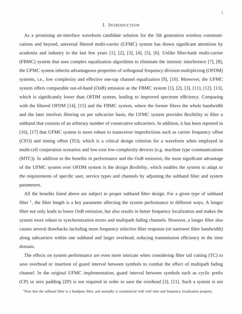
Universal filtered multi-carrier (UFMC) systems offer a flexibility of filtering arbitrary number of subcarriers
to suppress out of band (OoB) emission, while keeping the orthogonality between subbands and subcarriers within
one subband. However, subband filtering may affect system performance and capacity in a number of ways. In this
paper, we first propose the conditions for interference-free one-tap equalization and corresponding signal model in
the frequency domain for multi-user (MU) UFMC system. Basedon this ideal case, impact of subband filtering
on the system performance is analyzed in terms of average signal-to-noise ratio (SNR) per subband, capacity per
subcarrier and bit error rate (BER) and compared with the orthogonal frequency division multiplexing (OFDM)
system. This is followed by filter length selection strategies to provide guidelines for system design. Next, by
taking carrier frequency offset (CFO), timing offset (TO),insufficient guard interval between symbols and filter tail
cutting (TC) into consideration, an analytical system model is established. New channel equalization algorithms
are proposed by considering the errors and imperfections based on the derived signal models. In addition, a set
of optimization criteria in terms of filter length and guard interval/filter TC length subject to various constraints is
formulated to maximize the system capacity. Numerical results show that the analytical and corresponding optimal
approaches match the simulation results, and the proposed equalization algorithms can significantly improve the
BER performance.
Index Terms
universal filtered multi-carrier, transceiver imperfection, zero padding, optimization, one-tap interference-free
equalization, performance analysis
Lei Zhang, Ayesha Ijaz, Pei Xiao, Muhammad Ali Imran and Rahim Tafazolli are with the Institute for Communication Systems (ICS),
University of Surrey, Guildford, GU2 7XH, UK (Email:{lei.zhang, a.ijaz, p.xiao, m.imran, r.tafazolli}@surrey.ac.uk).
2
I. INTRODUCTION
As a promising air-interface waveform candidate solution for the 5th generation wireless communi-
cations and beyond, universal filtered multi-carrier (UFMC) system has drawn significant attentions by
academia and industry in the last few years [1], [2], [3], [4], [5], [6]. Unlike filter-bank multi-carrier
(FBMC) system that uses complex equalization algorithms toeliminate the intrinsic interference [7], [8],
the UFMC system inherits advantageous properties of orthogonal frequency division multiplexing (OFDM)
systems, i.e., low complexity and effective one-tap channel equalization [9], [10]. Moreover, the UFMC
system offers comparable out-of-band (OoB) emission as theFBMC system [1], [2], [3], [11], [12], [13],
which is significantly lower than OFDM system, leading to improved spectrum efficiency. Comparing
with the filtered OFDM [14], [15] and the FBMC system, where the former filters the whole bandwidth
and the later involves filtering on per subcarrier basis, theUFMC system provides flexibility to filter a
subband that consists of an arbitrary number of consecutivesubcarriers. In addition, it has been reported in
[16], [17] that UFMC system is more robust to transceiver imperfections such as carrier frequency offset
(CFO) and timing offset (TO), which is a critical design criterion for a waveform when employed in
multi-cell cooperation scenarios and low-cost low-complexity devices (e.g. machine type communications
(MTC)). In addition to the benefits in performance and the OoBemission, the most significant advantage
of the UFMC system over OFDM system is thedesign flexibility, which enables the system to adapt to
the requirements of specific user, service types and channels by adjusting the subband filter and system
parameters.
All the benefits listed above are subject to proper subband filter design. For a given type of subband
filter 1, the filter length is a key parameter affecting the system performance in different ways. A longer
filter not only leads to lower OoB emission, but also results in better frequency localization and makes the
system more robust to synchronization errors and multipathfading channels. However, a longer filter also
causes several drawbacks including more frequency selective filter response (or narrower filter bandwidth)
along subcarriers within one subband and larger overhead, reducing transmission efficiency in the time
domain.
The effects on system performance are even more intricate when considering filter tail cutting (TC) to
save overhead or insertion of guard interval between symbols to combat the effect of multipath fading
channel. In the original UFMC implementation, guard interval between symbols such as cyclic prefix
(CP) or zero padding (ZP) is not required in order to save the overhead [3], [11]. Such a system is not
1Note that the subband filter is a bandpass filter, and normallyis symmetrical with well time and frequency localization property.

3
orthogonal in multipath fading channel environments and one-tap equalization is not interference-free.
However, it has been claimed that the filter length takes approximately the same length as the CP length
in an OFDM system, leading to negligible performance loss [3], [4], [16]. This is due to soft protection,
against the multipath channel effect, provided by filter ramp up and ramp down at the edges of symbols.
However, this claim has not been proved analytically and it does not hold in some scenarios such as
harsh channel conditions, where the filter ramp up and ramp down at the edges of symbols might not
be sufficient to overcome the multipath channel and the performance loss is likely to be significant.
Alternatively, cyclic prefix (CP) as an option can be added toavoid the inter-symbol interference (ISI)
[1]. However, the system can not achieve interference-freeone-tap equalization either since the circular
convolution property is destroyed. On the other hand, filtertail can be cut partly (preferably from both
sides) to further reduce the system overhead as compared to the state-of-the-art (SoTA) UFMC system.
This operation may result in performance loss but reduces the overall overhead. However, OoB emission
level might be affected by the TC operation depending on the cutting length. In order to analyze the impact
of filter length, ZP/CP or filter TC on the performance of a UFMCsystem and give useful guidelines for
the system design, it is necessary to build a system model by taking all of the listed imperfection factors
into consideration in multipath fading channel. A comprehensive analytical framework is also essential
for optimal design of equalization and channel estimation algorithms.
Insufficient CP length with CFO and TO errors are modeled in [18] for OFDM systems and the optimal
CP length for maximizing capacity is formulated in [19]. Forthe UFMC system, the original UFMC has
been shown to be less susceptible to CFO and TO in comparison to CP-OFDM [3] via numerical results
and simulations. For analytical model, the performance of UFMC systems in the presence of CFO was
analyzed in [11] and a filter was optimized to minimize the outof band leakage (OBL) in [20] by
considering both CFO and TO. However, only single-path flat fading channel was considered in [11] and
[20]. In addition, the signal model in [20] is not fully derived as it contains convolution operation in the
analytical expression.
Theoretically, to completely eliminate the effect of multipath channel by one-tap channel equalization,
ZP/CP length longer or equal to the channel length should be added between UFMC symbols. However,
similar to an OFDM system, sufficient ZP/CP length may yield marginal performance improvement at
the cost of unnecessary overhead [19]. Moreover, in some scenarios (e.g., short channel length) ZP is not
required at all, and the filter TC might be necessary to further reduce the system overhead. Therefore,
for an optimal system, we conjecture that there is an optimallength of ZP/CP, filter TC and filter that is

4
neither too short to combat the channel multipath effect, CFO and TO, nor too long to compromise the
transmission efficiency. To the best of our knowledge, this is still an open issue for UFMC systems.
In this paper, we first consider an ideal case for MU-UFMC systems in Section II where the transceivers
are assumed to be perfectly synchronized without any CFO andTO. Propositions are made for interference-
free one-tap equalization, performance comparison to OFDMsystem and filter length selection. To reduce
the overhead and adapt imperfect transceiver, the signal model for MU-UFMC considering insufficient ZP
length, TC, CFO and TO is derived in Section III. In addition,new equalization algorithms are proposed
to improve the system performance. Based on this analyticalframework, a set of optimization problems in
terms of filter length and ZP length is formulated to maximizethe capacity in Section IV. The contributions
and novelties of this paper are summarized as follows:
• In the absence of transceiver imperfections (e.g., CFO, TO,etc.), we first make propositions to
illustrate the conditions for interference-free one-tap equalization and the corresponding system model
for MU-UFMC system. Then a set of proposition is proposed andproved for performance analysis in
terms of subband average output SNR, capacity per subcarrier and BER. These properties explain the
performance loss due to introducing subband filtering in UFMC systems in ideal case in comparison
to OFDM system. In addition, we define a new metric for UFMC subband filter, i.e., peak-to-bottom-
power-ratio (PBPR) as a key parameter to guide the filter length selection.
• We derive an analytical expression for MU-UFMC system signal in terms of desired signal, inter-
carrier interference (ICI), inter-symbol interference (ISI) and noise by considering insufficient ZP
length, filter TC, CFO and TO. This analytical framework provides useful guidelines for practical
algorithm design and further system performance analysis.The work also explains why the UFMC
system is robust to dispersive channels and transceiver imperfections. In addition, it also calculates
how much performance loss will be incurred in a given channeland transceiver imperfections.
• We propose a set of optimization criteria in terms of filter, ZP (or TC) length to maximize the system
capacity. We start from a set of capacity optimization problems without the overhead constraint. This
can be done e.g. by fixing filter length to optimize the ZP (or TC) length, or vice versa, or in a
more general case, optimizing both filter length and ZP (or TC) length to achieve the global optimal
solutions. On the other hand, when the system is designed with a fixed overhead, we optimize the
proportion between filter length and ZP length to maximize the system capacity. The optimization
problems represent different system design criteria to meet different design requirements in various
environments.
5
• Based on the analytical framework and the derived variancesof ICI and ISI, we propose a set of
channel equalization algorithms, by considering not only the noise but also the interference, which
can provide significant gain in terms of BER performance in comparison to OFDM and the SoTA
UFMC systems.
Notations: Vectors and matrices are denoted by lowercase and uppercase bold letters, and{·}H, {·}T , {·}∗
stand for the Hermitian conjugate, transpose and conjugateoperation, respectively.E{a} denotes the
expectation ofa. We use trace{A} to denote taking the trace of matrixA. diag{a} refers to reframe a
diagonal matrix with its diagonal elements being the elements of vectora. IM and0m×n refer toM ×M
identity matrix andm×n zero matrix, respectively. Operator∗ denotes linear convolution of two vectors.
⌈a⌉ and⌊a⌋ denote floor and ceiling operations ona, respectively.
II. MU-UFMC SYSTEM MODEL AND PERFORMANCE ANALYSIS IN THE ABSENCE OFTRANSCEIVER
IMPERFECTION
A. MU-UFMC System
Let us consider a multicarrier system withN subcarriers with the index setU = [0, 1, · · · , N − 1].
The N subcarriers are divided intoM subbands with them-th subband comprising ofNm consecutive
subcarriers from setU andN0+N1+ · · ·NM−1 = N 2. It implies that the subcarrier index set for them-th
subband isUm = [∑m−1
i=0 Ni,∑m−1
i=0 Ni + 1, · · · ,∑m
i=0Ni − 1]. Note that the following derivations are for
downlink transmission, however, the basic idea can be easily extended to uplink. In the MU scenario, we
assume that theM subbands are assigned toK users each occupying from at least 1 to several subbands
depending on system design and radio resource management. The subbands allocated to one user can be
either contiguous or non-contiguous to achieve frequency diversity gain.
Assume the modulated symbols transmitted on theN subcarriers area = [a(0), a(1), · · · , a(N − 1)]T
and E{|a(i)|2} = ρ2sym , for i = 0, 1, · · · , N − 1. Split the vectora into non-overlapping sub-vectors
as a = [a0; a1; · · · ; aM−1], wheream = [a(∑m−1
i=0 Ni), a(∑m−1
i=0 Ni + 1), · · · , a(∑m
i=0Ni − 1)]T is an
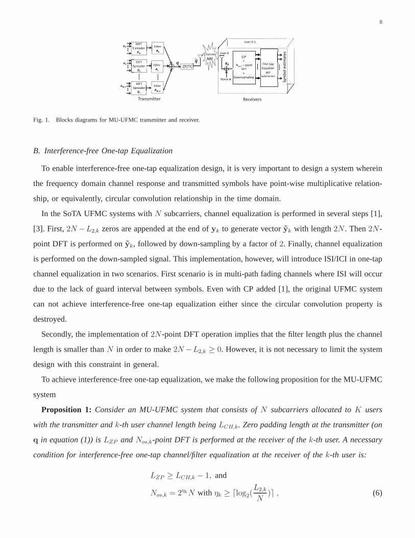
Nm column vector consisting of symbolsa(i) transmitted in them-th subband, as shown in Fig. 1. Let
us assume that them-th subband filter isfm = [fm(0), fm(1), · · · , fm(LF,m − 1)] and without of loss
generality, we assume that the power offm is normalized to unity, i.e.,∑LF,m−1
i=0 |fm(i)|2 = 1. Generally,
the filter lengths for different subbands (e.g.,LF,m1 andLF,m2) are not necessarily the same, particularly
2This equation implies that all of theN consecutive subcarriers are occupied. Otherwise, the transmitting symbols can be set to zero at
the unoccupied subcarriers to satisfy the assumption.

6
for the subbands assigned to different users. For a unified expression for MU-UFMC, let us assume
LF,max = max(LF,m) for m ∈ [0, 1, · · · ,M−1] and defineAm ∈ C(N+LF,max−1)×N as the Toeplitz matrix
of fm with its first column beingfm = [fm, 01×(N+LF,max−1−LF,m)]T ∈ C(N+LF,max−1)×1 and first row being
[fm(0), 01×(N−1)] ∈ C1×N . We can write the transmitted signal after subband filtering, as shown in Fig.
1, as:
q =M−1∑
m=0
1
ρmfm ∗ (Dmam) =
M−1∑
m=0
1
ρmAmDmam , (1)
whereDm ∈ CN×Nm is the (∑m−1
i=0 Ni + 1)-th to the(∑m
i=0Ni)-th columns of theN-point normalized
IDFT (inverse discrete Fourier transform) matrixD. The element ofD in the i-th row andn-th column
is di,n = 1√Nej·2πin/N . ρm =
√
1Nm
trace(DHmA
HmAmDm) is the transmission power normalization factor of
them-th subband. Due to the filter tail,q is LF,max − 1 samples longer than the original input signala.
Unlike the OFDM system that treats all subcarriers equally by a unified IDFT operation, equation
(1) implies that UFMC implemented in Fig. 1 splits the whole bandwidth into subband and the signals
transmitting in each subbandam is operated by the IDFT and subband filter in series. Then the processed
signals in all subbands1ρm
AmDmam are summed together for transmission to the receivers.
Two different operations can be performed before transmitting filtered signal to the users via wireless
channel, as shown in Fig. 1. One can either insert CP/ZP between symbols to combat the effect of
multipath channel fading or cut the filter tails from either sides ofq in order to reduce overhead albeit at
the expense of performance loss. The former may result in performance gain in harsh channel conditions
but would incur additional overhead in the system in addition to filter tails. Note that ZP and CP insertion
are equivalent to OFDM in terms of SNR performance in the ideal case3 [23]. In this paper, we only
consider zero padding and the model for CP insertion can be derived in a similar way. For brevity, in
the rest of the paper, we will use OFDM to refer to ZP-OFDM, unless specified otherwise. On the other
hand, the tail cutting operation saves the overhead but may result in performance loss due to the loss
of the filter integrity. To unify the expression of ZP and filter TC scenarios and simplify the following
derivations by a single parameterLZP , we define
q=
[q; 0LZP×1]∈ C(N+LF,max−1+LZP )×1 if LZP ≥ 0
q∈ C(N+LF,max−1+LZP )×1 if LZP < 0(2)
q is the filter vector after tail cutting comprising of the(⌊ |LZP |2
⌋+1)-th to the(N + LF,max − |LZP | +⌊ |LZP |
2⌋ − 1)-th elements ofq. In other words, the front⌊ |LZP |
2⌋ and the end|LZP | − ⌊ |LZP |
2⌋ elements of
3However, one should note that the CP and ZP OFDM systems can have different power spectrum density performance [21], [22].
7
q are cut off to reduce overhead. Theoretically, the TC length|LZP | should be less thanLF,max − 1 to
keep the length ofq equal to or larger thanN . However, in most cases, for low level of OoB emission,
we should keep the TC length much smaller than the filter length, i.e., |LZP | << LF,max.
Equation (2) indicates that whenLZP ≥ 0, ZP will be performed onq before it is transmitted over the
wireless channel, while filter TC will be performed onq whenLZP < 0. However, whetherLZP ≥ 0 or
LZP < 0, the UFMC symbol length will beN +LF,max+LZP −1 and the overhead isLF,max+LZP −1,
which is attributed to both filter tails and ZP/TC.
Let us assume the channel between the transmitter and thek-th user at timet ishk(t) = [hk(0, t), hk(1, t),
· · · , hk(LCH,k − 1, t)] where LCH,k is the length of the channel in UFMC samples. Without loss of
generality, we assume the overall channel gain for thek-th user is∑LCH,k−1
i=0 E|hk(i, t)|2 = ρ2CH,k. Using
equation (1), the received signal at thek-th user can be written as:
yk = hk(t) ∗ q = Bk(t)
M−1∑
m=0
AmDmam + yk,ISI + vk , (3)
wherevk = [vk(0), vk(1), · · · , vk(N + LF,max + LCH,k − 2)]T is a complex-valued noise vector for the
k-th user and its elements are drawn from Gaussian distribution with zero mean and varianceσ2. Bk(t) ∈C(N+LF,max+LCH,k−2)×(N+LF,max−1) is the equivalent channel convolution Toeplitz matrix ofhk(t). yk,ISI
is the ISI due to insufficient ZP length. In the ideal scenariowithout ISI, i.e., foryk,ISI = 0, the ZP
length should be such thatLZP ≥ LCH,k − 1. This condition will be given and proved in Proposition 1
in the next subsection. However, the detailed expression for the ISI yk,ISI will be given in Section III in
the presence of synchronization errors and insufficient guard interval between symbols. WhenLZP = 0
andK = 1, the system model in (3) is equivalent to SoTA UFMC system [1], [3]. On the other hand,
whenLF,m = 1, (3) is equivalent to an OFDM system.
We assume that the channel vectorhk(t) has the following property [9], [10]:
E{hk(l1, t1)h∗k(l2, t2)} = δ(l1 − l2)Rk(l1, t1 − t2) , (4)
whereRk(l1, t1 − t2) is the autocorrelation function of the channelhk(t) at thel1-th path andl2-th path
at timet1 and t2. δ(l) is the Kronecker delta function withδ(l) = 1 for l = 0 andδ(l) = 0 for l 6= 0. (4)
implies that the channel taps are uncorrelated.
To simplify the derivation that follows, let us define:
L1 = N + LF,max − 1, L2,k = L1 + LCH,k − 1
L3 = N + LF,max − 1 + LZP . (5)
8
aM-1
Transmitter
IDFT
Spreader
D1
Spa1
IDFT
Spreader
D0
a0 Filter
A0
Filter
A0
Filter
A1
Filter
A1
F
Filter
AM-1
Filter
AM-1
Receivers
IDFT
Spreader
D1
IDFT
Spreader
D0
Sp
IDFT
Spreader S
D1
F
F
A
ZP/TC
User 0
y0
S/P
+
Nos,0 – point
DFT
+
Downsampling
One-tap
Equalizer
per
subcarrier
Sym
bo
l e
stim
ate
s User 0
y0
S/P
+
Nos,0 – point
DFT
+
Downsampling
One-tap
Equalizer
per
ubcarriersu
Sym
bo
l e
stim
ate
s
User K-1
Noise v
y
tes
ma
ta
tSy
m
Channel
h(t)
Fig. 1. Blocks diagrams for MU-UFMC transmitter and receiver.
B. Interference-free One-tap Equalization
To enable interference-free one-tap equalization design,it is very important to design a system wherein
the frequency domain channel response and transmitted symbols have point-wise multiplicative relation-
ship, or equivalently, circular convolution relationshipin the time domain.
In the SoTA UFMC systems withN subcarriers, channel equalization is performed in severalsteps [1],
[3]. First, 2N −L2,k zeros are appended at the end ofyk to generate vectoryk with length2N . Then2N-
point DFT is performed onyk, followed by down-sampling by a factor of2. Finally, channel equalization
is performed on the down-sampled signal. This implementation, however, will introduce ISI/ICI in one-tap
channel equalization in two scenarios. First scenario is inmulti-path fading channels where ISI will occur
due to the lack of guard interval between symbols. Even with CP added [1], the original UFMC system
can not achieve interference-free one-tap equalization either since the circular convolution property is
destroyed.
Secondly, the implementation of2N-point DFT operation implies that the filter length plus the channel
length is smaller thanN in order to make2N −L2,k ≥ 0. However, it is not necessary to limit the system
design with this constraint in general.
To achieve interference-free one-tap equalization, we make the following proposition for the MU-UFMC
system
Proposition 1: Consider an MU-UFMC system that consists ofN subcarriers allocated toK users
with the transmitter andk-th user channel length beingLCH,k. Zero padding length at the transmitter (on
q in equation (1)) isLZP andNos,k-point DFT is performed at the receiver of thek-th user. A necessary
condition for interference-free one-tap channel/filter equalization at the receiver of thek-th user is:
LZP ≥ LCH,k − 1, and
Nos,k = 2ηkN with ηk ≥ ⌈log2(L2,k
N)⌉ , (6)

9
and the signal model for then-th subcarrier of thek-th user in them-th subband is
zk(n) =1
ρm√2ηk
Hk(n, t)Fm(n)a(n) + vos,k(n) , (7)
where vos,k(n) =∑L2,k−1
l=01√Nos,k
e−j2πnl/Nvk(l) is the noise after DFT and down-sampling operations.
Hk(n, t) =∑LCH,k−1
l=0 e−j2πnl/Nhk(l, t) andFm(n) =∑LF,m−1
l=0 e−j2πnl/Nfm(l) are the channel and filter
response infrequency domain, respectively.
Proof: See Appendix A.
From equation (7), it is obvious that the subcarriers are decoupled in frequency domain and the standard
one-tap channel equalization algorithms such as ZF or MMSE can be applied. Note thatLCH,k andLF,m
could be larger thanN . If LCH,k ≤ N andLF,m ≤ N , thenHk(n, t) andFm(n) are then-th element of
N-point DFT transformation ofhk(t) and fm, respectively. In any case, we haveE|Hk(n, t)|2 = ρ2CH,k
and∑N−1
n=0 E|Fm(n)|2 = Nm
∑LF,m−1i=0 |fm(i)|2 = Nm.
Proposition 1 gives conditions for interference-free equalization for userk in the MU-UFMC system.
If we aim to achieve an interference-free system for allK users, the condition is specified asLZP ≥LCH,max − 1 and Nos = 2ηmaxN with ηmax ≥ ⌈log2(L2,max
N)⌉, whereL2,max = max(L2,k) for k =
0, 1, · · · , K − 1.
Proposition 2: Consider an MU-UFMC system and the parameters setting for the k-th user satisfying
Proposition 1. The SNR at then-th subcarrier of userk in subbandm can be written as:
E{SNR(n)} =1
ρ2m2ηk
E|Hk(n, t)Fm(n)a(n)|2E|vos,k(n)|2
=N
L2,k·ρ2symσ2
· ρ2CH,k ·1
ρ2m· |Fm(n)|2 . (8)
Proof: Note that E|Hk(n, t)Fm(n)a(n)|2 = ρ2CH,kρ2sym|Fm(n)|2 since E|Hk(n, t)|2 = ρ2CH,k and
E|a(n)|2 = ρ2sym. Noise variance is given byE|vos,k(n)|2 = E|∑L2,k−1
l=01√Nos,k
e−j2πnl/Nvk(l)|2 =∑L2,k−1
l=0
1Nos,k
E|vk(l)|2 = L2,k/Nos,kσ2. SubstitutingNos,k = 2ηkN and expressions of signal and noise power into
E{SNR(n)} leads to equation (8).
The SNR at then-th subcarrier depends on the subband indexm and the location of the subcarrier
in the subband (i.e., indexn), i.e., it is proportional to 1ρ2m
and |Fm(n)|2. The latter in general is fixed
but varies along the subcarriers in a particular subband. Fig. 2 gives an example of FIR Chebyshev
filter response in frequency domain (i.e.,|Fm(n)|2) at different subcarriers. It clearly shows that the filter
response depends on filter length and is frequency selectivealong subcarriers. It is also noted that the
variance is considerably large when the filter length increases.

10
0 5 10 15 20 25 30 3510
−2
10−1
100
101
Subcarrier index: n
Filt
er g
ain
|Fm
(n)|
2
LF,m
= 20
LF,m
= 40
LF,m
= 1 (OFDM)L
F,m = 60
Subband 0 Subband 1 Subband 2
Fig. 2. Filter frequency response in 3 consecutive subbandsfor different filter length (N = 240, Chebyshev filter with OoB emission level
−50 dB).
When filter lengthLF,m = 1, equation (8) leads to an OFDM system with sufficient ZP length. Then
Fm(n) is constant along the subcarriers (as shown in Fig. 2) andL2,k = N+LCH,k−1 with LCH,k−1 being
the ZP length. We can easily obtainρ2m = 1, then signal model in (7) becomesz(n) = 1√2ηk
Hk(n, t)a(n)+
vos,k(n). Consequently, (8) represents SNR for interference-free ZP-OFDM system as:
E{SNRofdm} =N
L2,k
·ρ2symσ2
· ρ2CH,k for n ∈ U . (9)
It can be concluded that UFMC is a generalized OFDM system. Inaddition, equation (9) confirms that the
SNR of then-th subcarrier is independent of its location in a subband and subband index itself. Therefore,
the subband index{}m and subcarrier indexn are omitted in the sequel.
C. Performance analysis and comparison with OFDM System
In comparison to OFDM system, Fig. 2 shows positive filter gain in the middle of a subband and negative
filter gain at its edges. In order to present an overall view ofthe system performance in comparison to
OFDM system, we focus on the average performance in one subband, in terms of output SNR, capacity
and BER.
1) Output SNR:The frequency selectivity of the filter is the essence of the UFMC system design to
make the system well-localized in the frequency domain to combat multipath channel and reduce the OoB
emission. However, similar to the side effects of the channel frequency selectivity, the filter frequency
selectivity may cause system performance loss, as analyzedin the following proposition:

11
Proposition 3: Consider an MU-UFMC system withLF,m > 1 and the parameters for thek-th user
satisfying equation (6) in Proposition 1. The subband filtering leads to performance loss in terms of
average output SNR along the subcarriers inm-th subband in comparison to the OFDM system, i.e.,
E{SNRm} =1
Nm
∑
n∈Um
E{SNR(n)} ≤ E{SNRofdm} . (10)
The equality holds only whenM = 1.
Proof: See Appendix B.
This proposition implies that in the ideal case when equation (6) is satisfied, the UFMC system with
only one subband will have the same performance as the OFDM system in terms of average SNR.
2) Capacity: The conclusion can be extended to system capacity without considering the overhead in
high SNR region.
Proposition 4: Consider an MU-UFMC system withLF,m > 1 and assume the parameters for thek-th
user satisfy equation (6) in Proposition 1. In addition, we assume the subband bandwidth is small enough
to be within the coherence bandwidth. In the high-SNR region, i.e.,SNR(n) >> 1, the MU-UFMC system
incurs performance loss in terms of average capacity per subcarrier in them-th subband in comparison
to the OFDM system, i.e.,
Cm ≈ 1
NmE [∑
n∈Um
log2(SNR(n)] ≤ Cofdm . (11)
The approximation leads to the relationshipCm = Cofdm ≈ E(log2[α1/ρ2m|Hk(i, t)|2) with α =
N/L2,kρ2sym/σ
2 only whenM = 1, i.e., the bandwidth has one subband only.
Proof: See Appendix C.
3) BER: Now we analyze the BER performance of quadrature amplitude modulation (QAM) schemes.
The BER forMmod-QAM can be calculated as [24]:
BER(n) = 2(1− 1√Mmod
)Q
(
√
3SNR(n)
Mmod − 1
)
. (12)
The calculation of analytical BER expression is complex dueto the Q-functionQ(·). Thus, we use the
following approximation of the Q-function as proposed in [24]:
Q(x) ≈ 1
12e−
x2
2 +1
6e−
2x2
3 . (13)
Based on the approximation in (13), we have the following proposition:
Proposition 5: Let us consider the same system as that assumed in Proposition 4. UFMC system in
the m-th subband suffers performance loss in terms of average BERin the m-th subband as compared

12
to the OFDM system, i.e.,
BERm ≥ BERofdm , (14)
whereBERm = 1Nm
E{∑
n∈UmBERm(n)} andBERofdm ≈ E(e−φ1|Hk(n,t)|2α+ e−φ2|Hk(n,t)|2α), with φ1 =
32(Mmod−1)
, φ2 =2
(Mmod−1).
Proof: See Appendix D.
Similarly, we have 1Nm
∑
n∈Ume−φ2SNR(n) ≥ e−φ2|Hk(i,t)|2α. Therefore,BERm ≥ E(e−φ1|Hk(i,t)|2α +
e−φ2|Hk(i,t)|2α) = BERofdm.
Proposition 5 concludes that due to the introduction of the filter and unequal power allocation to different
subcarriers, the average BER performance in one subband is worse than OFDM system. This is due to
frequency selective filter response that is higher in the middle of the subband than the subcarriers at the
edges. This leads to a high possibility of erroneous detection at the edges, while the response at middle
subcarriers may be sometimes unnecessarily high leading topower waste.
D. Filter Length Selection
For a given type of filter, it is usually recommended that the filter length should be comparable to the
channel length (or CP length in CP-OFDM systems), as proposed in the SoTA UFMC system [1], [3],
[16], [4]. This claim is neither accurate nor generally applicable to all scenarios. As mentioned earlier,
filter length impacts the performance in different ways. Without considering CFO, TO and insufficient ZP
length, longer filter length leads to greater frequency selectivity and less effective power allocation along
the subcarriers in a subband, resulting in performance loss.
Proposition 6: Consider two subbands which satisfy the interference-freecondition in Proposition 1,
and assume the same parameters for both of them including channel, whole bandwidth and subband
bandwidth. Assume the filter lengthLF,m1 ≤ LF,m2, then subband 1 outperforms subband 2 in terms of
average output SNR, capacity per subcarrier and BER.
Proposition 6 gives an intuition of filter length impact on the subbands with the same parameters.
However, when two subbands have different parameter settings such as different bandwidth (e.g., when
the two subbands belong to two different UFMC systems) or subbands bandwidth, the selection of the filter
length and performance comparison is complex since the filter response at all corresponding subcarriers
in the two subbands is different. In other words, to select a filter to achieve a given performance, we have
to consider the performance ineverysubcarrier within the subband as proposed in Proposition 3,4 and
5, which results in a very complex procedure.
13
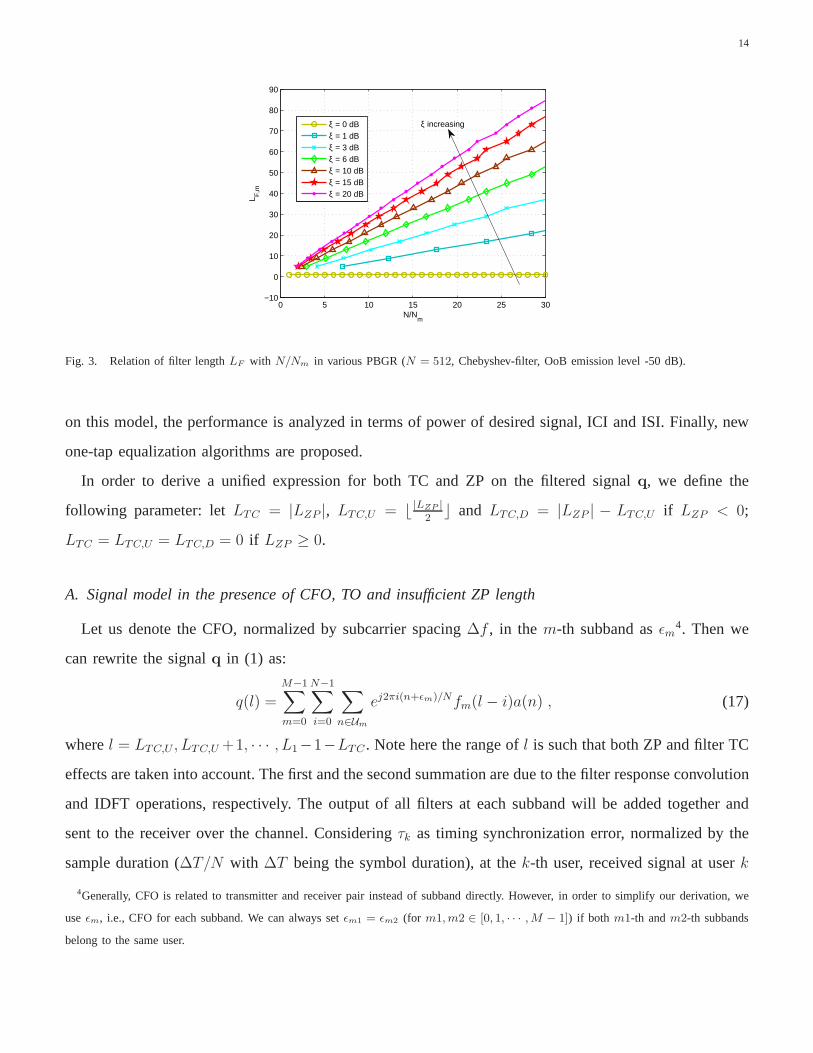
To simplify the filter length selection procedure for a givenperformance, let us define a new metric:
filter peak-to-bottom-gain-ratio (PBGR) in one subband as
ξ =|Fm(⌈Nm
2⌉)|2
|Fm(0)|2, (15)
whereFm(⌈Nm
2⌉) andFm(0) are filter frequency response at the middle and edge of them-th subband,
respectively. Instead of using filter response at all subcarriers in a subband, we exploit the single parameter
ξ to map the subband performance approximately. To show the effectiveness of the simplification, we use
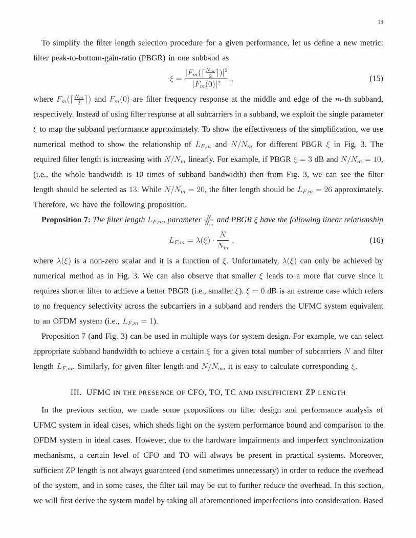
numerical method to show the relationship ofLF,m and N/Nm for different PBGRξ in Fig. 3. The
required filter length is increasing withN/Nm linearly. For example, if PBGRξ = 3 dB andN/Nm = 10,
(i.e., the whole bandwidth is 10 times of subband bandwidth)then from Fig. 3, we can see the filter
length should be selected as13. While N/Nm = 20, the filter length should beLF,m = 26 approximately.
Therefore, we have the following proposition.
Proposition 7: The filter lengthLF,m, parameter NNm
and PBGRξ have the following linear relationship
LF,m = λ(ξ) · N
Nm, (16)
whereλ(ξ) is a non-zero scalar and it is a function ofξ. Unfortunately,λ(ξ) can only be achieved by
numerical method as in Fig. 3. We can also observe that smaller ξ leads to a more flat curve since it
requires shorter filter to achieve a better PBGR (i.e., smaller ξ). ξ = 0 dB is an extreme case which refers
to no frequency selectivity across the subcarriers in a subband and renders the UFMC system equivalent
to an OFDM system (i.e.,LF,m = 1).
Proposition 7 (and Fig. 3) can be used in multiple ways for system design. For example, we can select
appropriate subband bandwidth to achieve a certainξ for a given total number of subcarriersN and filter
lengthLF,m. Similarly, for given filter length andN/Nm, it is easy to calculate correspondingξ.
III. UFMC IN THE PRESENCE OFCFO, TO, TCAND INSUFFICIENT ZP LENGTH
In the previous section, we made some propositions on filter design and performance analysis of
UFMC system in ideal cases, which sheds light on the system performance bound and comparison to the
OFDM system in ideal cases. However, due to the hardware impairments and imperfect synchronization
mechanisms, a certain level of CFO and TO will always be present in practical systems. Moreover,
sufficient ZP length is not always guaranteed (and sometimesunnecessary) in order to reduce the overhead
of the system, and in some cases, the filter tail may be cut to further reduce the overhead. In this section,
we will first derive the system model by taking all aforementioned imperfections into consideration. Based
14
0 5 10 15 20 25 30−10
0
10
20
30
40
50
60
70
80
90
N/Nm
L F,m
ξ = 0 dBξ = 1 dBξ = 3 dBξ = 6 dBξ = 10 dBξ = 15 dBξ = 20 dB
ξ increasing
Fig. 3. Relation of filter lengthLF with N/Nm in various PBGR (N = 512, Chebyshev-filter, OoB emission level -50 dB).
on this model, the performance is analyzed in terms of power of desired signal, ICI and ISI. Finally, new
one-tap equalization algorithms are proposed.
In order to derive a unified expression for both TC and ZP on thefiltered signalq, we define the
following parameter: letLTC = |LZP |, LTC,U = ⌊ |LZP |2
⌋ and LTC,D = |LZP | − LTC,U if LZP < 0;
LTC = LTC,U = LTC,D = 0 if LZP ≥ 0.
A. Signal model in the presence of CFO, TO and insufficient ZP length
Let us denote the CFO, normalized by subcarrier spacing∆f , in them-th subband asǫm4. Then we
can rewrite the signalq in (1) as:
q(l) =
M−1∑
m=0
N−1∑
i=0
∑
n∈Um
ej2πi(n+ǫm)/Nfm(l − i)a(n) , (17)
wherel = LTC,U , LTC,U +1, · · · , L1−1−LTC . Note here the range ofl is such that both ZP and filter TC
effects are taken into account. The first and the second summation are due to the filter response convolution
and IDFT operations, respectively. The output of all filtersat each subband will be added together and
sent to the receiver over the channel. Consideringτk as timing synchronization error, normalized by the
sample duration (∆T/N with ∆T being the symbol duration), at thek-th user, received signal at userk
4Generally, CFO is related to transmitter and receiver pair instead of subband directly. However, in order to simplify our derivation, we
useǫm, i.e., CFO for each subband. We can always setǫm1 = ǫm2 (for m1,m2 ∈ [0, 1, · · · ,M − 1]) if both m1-th andm2-th subbands
belong to the same user.

15
can be expressed as:
yk(r) =∞∑
e=−∞
L1−1−LTC∑
l=LTC,U
M−1∑
m=0
N−1∑
i=0
∑
n∈Um
ej2πi(n+ǫm)/N ·
hk(r − l − eL3 + τk + LTC,U , t)fm(l − i)a(n) , (18)
wherer = 0, 1, · · · , L3−1. According to the Proposition 1, one of the conditions fork-th user to achieve
the interference-free one-tap channel equalization is to set LZP ≥ LCH,k − 1. Therefore,yk(r) = 0 for
r = L3, L3 + 1, · · · , L2,k − 1. Generally, the selected ZP length is insufficient to reducethe overhead in
the system. In other words, the non-zeroy(r) for r = L3, L3 + 1, · · · , L2,k − 1 will overlap with the next
UFMC symbol, causing ISI.
Let us assumeNos,k = 2ηkN point DFT is performed onyk(r, t) followed by down sampling by factor
of ηk. Therefore,
xk(d) =
L3∑
r=0
∞∑
e=−∞
L1−1−LTC∑
l=LTC,U
M−1∑
m=0
N−1∑
i=0
∑
n∈Um
ej2π[i(n+ǫm)−dr]
N ·
hk(r−l−eL3+τk+LTC,U , r−τk)fm(l−i)a(n)+vos,k(d) (19)
Equation (19) is a complete signal model taking the insufficient ZP, CFO and TO into consideration.
xk(d) is a lengthN series and onlyxk(d) at d-th subcarrier that belongs tok-th user will be extracted
for further symbol detection. In the next subsection, we will split (19) into three components, i.e., desired
signal, ICI and ISI and express their powers for SINR and capacity calculation.
B. Performance analysis
Let us assume that then-th subcarrier of the multicarrier symbol belongs to thek-th user and them-th
subband. The modulated symbolsan1 andan2 are uncorrelated ifn1 6= n2 ∀n1, n2 ∈ U . Moreover, since
information symbols within different UFMC symbols are uncorrelated andE|a(n)|2 = ρ2sym, we can write
the power of the signal received at then-th subcarrier in terms of desired signal, ISI, ICI and noiseas
follows:
Px(n) = PD(n) + PICI(n) + PISI(n) +L2,k
Nσ2 , (20)

16
where
PD(n) = ρ2symE|β(n, n, 0)|2 ,
PICI(n) = ρ2sym∑
t∈Um,t6=n
E|β(n, t, 0)|2 ,
PISI(n) = ρ2sym
∞∑
e=−∞,e 6=0
∑
t∈Um
E|β(n, t, e)|2 , (21)
andβ(n, t, e) can be expressed as:
β(n, t, e) =L3∑
r=0
L1−1−LTC∑
l=LTC,U
M−1∑
m=0
N−1∑
i=0
ej2π[i(n+ǫm)−rt]
N
hk(r − l − eL3 + τk + LTC,U , r − τk)fm(l − i) . (22)
To simplify the derivation of|β(n, t, e)|2, let us define
Tm(l1, l2) = Bm(l1)B∗m(l2) , (23)
whereBm(l1) =∑N−1
i=0 ej2πi(n+ǫm)
N fm(l − i). Using (23), we have
E|β(n, t, e)|2 =L1−1−LTC∑
l1=LTC,U
l1∑
l2=LTC,U
M−1∑
m=0
Tm(l1, l2)
L3∑
r=l1−l2
e−j2πt(l1−l2)
N R(r − l1 + τk + LTC,U , l1 − l2)
+
L1−1−LTC∑
l1=LTC,U
L1−1−LTC∑
l2=l1
M−1∑
m=0
Tm(l1, l2)
L3−1−(l2−l1)∑
r=l1−l2
e−j2πt(l1−l2)
N R(r − l1 + τk + LTC,U , l1 − l2) . (24)
In the presence of interference, the SINR of then-th subcarrier can be written as
SINR(n) =PD(n)
PICI(n) + PISI(n) + σ2L2,k/N. (25)
Taking the overhead into consideration, the capacity of thewhole bandwidth can be written as
C =N
L3
N−1∑
n=0
log2[1 + SINR(n)] , (26)
whereL3 = N + LF,max − 1 + LZP is the symbol length andNL3
is the spectrum efficiency factor.
17
C. Channel Equalization
Based on the derived signal model in the presence of receiverimperfections and insufficient ZP/TC
length, the channel equalization algorithms can be updatedaccordingly. In this paper, two most widely
used linear equalizers: ZF (zero-forcing) and MMSE (minimum mean square error) are considered. The
equalizer for then-th subcarrier can be expressed as
Wn =β(n, n, 0)H
|β(n, n, 0)|2 + νσ2eff/ρ
2sym
, (27)
whereν is a parameter defined by
ν =
0 ZF receiver
1 MMSE receiver(28)
and
σ2eff = PISI + PICI +
L2,k
Nσ2 , (29)
whereσ2eff is the effective noise power taking ISI and ICI into consideration.
IV. FILTER LENGTH AND ZP LENGTH OPTIMIZATION
According to the capacity expression in (26) and the SINR in (25), the capacity of the UFMC system
are affected by two adjustable factors, i.e., filter length and ZP/TC length, in an intricate manner. It
is obvious from (26) that unnecessarily long filter length and ZP length/TC length is likely to lead to
capacity reduction due to the overhead. On the other hand, too short ZP and filter length/TC length may
also cause performance loss since system is not robust against the various imperfections and multipath
fading channels. Next, we design the optimal UFMC system maximizing capacity subject to various
constraints.
1) Optimal filter and ZP length without total overhead constraint: In the first instance, let us consider
the case when filters in all subbands have the same length, i.e., LF,0 = LF,1 = · · · , LF,M−1 = LF,equal.
By fixing the filter lengthLF,m to a constant value, we can formulate the following optimization problem
in terms of ZP/TC lengthLZP to maximize system capacity:
maxLZP
C s.t. LF,equal = LF and LZP ≥ LZP , (30)
whereLF is a constant integer larger than zero. The second constraint is only required for TC case to avoid
high level of OoB emission level. Unfortunately, the optimization problem can not be solved analytically
due to the complex cost function. In the simulations, numerical methods will be adopted to solve (30).

18
On the other hand, we can optimize the filter length subject toa constraint on the ZP length:
maxLF,equal
C s.t. LZP = LZP and LF,equal ≥ LF . (31)
The constraintLF,equal ≥ LF > 0 is added to meet the required OoB emission level. Again,LZP is a
constant and it is not necessarily greater than zero.
Optimization problems in equation (30) and (31) are likely to yield local optimal values since bothLF,m
andLZP affect the performance and they are correlated. Therefore,we define the following generalized
global optimization problem:
maxLZP ,LF,equal
C s.t. LF,equal ≥ LF . (32)
Comparing to (30) and (31), (32) is an unconstrained optimization on either filter length or ZP length
and, consequently leads to global optimization in terms of capacity.
2) Equal ZP and filter length for all subbands with overhead constraint: For a given system with
fixed overhead budget (i.e., filter length plus ZP/TC length), selection of filter length and ZP length, such
that their sum does not exceed the overhead budget, is another optimization problem of interest. For
instance, reasonably longer filter length can improve the system frequency and time localization property
and make it more robust to multipath fading channel, CFO and TO. However, it also implies a shorter ZP
length and larger ISI may be caused in the multipath fading channel. Therefore, the capacity maximization
optimization problem can be formulated as:
maxLZP ,LF,equal
C s.t. LF,equal + LZP = LOH
and LF,equal ≥ LF , (33)
whereLOH is the system overhead that is equal to or lager than zero. Unlike (30), (31) and (32), where
the overall overhead is not a constraint, the optimization in (33) can be conducted only by distributing the
allocated overhead between filter length and ZP length. Therefore, optimization in (33) can not outperform
(32). However, this optimization is suitable for the scenarios wherein the system is designed with fixed
overhead.
3) Unequal ZP and filter length for all subbands with overheadconstraint: In the multi-user case, it is
reasonable to assume that each user experiences a differentchannel and has different receiver performance.
Therefore, the optimization can be performed within each user subject to the equal symbol length (i.e.,
filter length plus ZP length for each user equals a constant).Then optimization (33) can be generalized

19
as
maxLZP ,LF
C s.t. LF + LZP = LOH1
and LF,m ≥ LF for m = 0, 1, · · · ,M − 1 , (34)
whereLZP = [LZP,0, LZP,1, · · · , LZP,M−1] and LF = [LF,0, LF,1, · · · , LF,M−1]. With different subband
bandwidths, channel lengths or different receivers in MU case, (34) gives more degree of freedom to
adjust the parameters as compared to optimization in (33). This is likely to lead to better performance in
versatile environments. However, the complexity of (34) ismuch higher than optimization problem (33)
since the search space isLMOH instead ofLOH for (33).
V. NUMERICAL RESULTS
In this section, we use Monte-Carlo simulations to compare the simulated and analytical results to verify
the accuracy of derived signal models in (20) and the proposed propositions. In addition, the optimization
problems proposed in (30), (31), (32) and (33) will be examined in various channels and transceiver
imperfections. Finally, we will verify the proposed equalization algorithms in (27) and compare with
OFDM and SoTA UFMC systems in terms of BER.
We adopt the 3rd Generation Partnership Project (3GPP) LongTerm Evolution (LTE)/LTE-A defined
radio frame structure, i.e., the whole bandwidth consists of 1200 subcarriers with subcarrier spacing
∆f = 15 KHz and the symbol duration∆T = 1/∆f = 1/15000 s. In order to demonstrate the results
clearly and without loss of generality, we consider that themiddleN = 36 subcarriers have been divided
into M = 3 equal bandwidth subbands occupied byK = 3 users, i.e.,Ni = 12 for i = 0, 1, 2. Simulations
are performed in three 3GPP specified channel models, i.e., Extended Pedestrian-A (EPA), Extended
Vehicular-A (EVA) and Extended Typical Urban (ETU) [9] as well as International Telecommunication
Union (ITU) specified channel model for Hilly Terrain (HT). We assume that the channel is static between
the adjacent symbols. The signal is modulated using 16-QAM with normalized power and the input SNR
is controlled by the noise variance. We adopt FIR Chebyshev filter [1] with 50 dB side lobe attenuation.
For fair comparison, we assume the ZP length for OFDM system is the same as the total overhead for
UFMC system (i.e.,LF,max − 1 + LZP ). We also provide the results of ideal case (i.e., no CFO, TO and
sufficient ZP length) for both UFMC and OFDM systems as benchmarks.
A. Signal model verification
To investigate the effect of CTO, TO and insufficient ZP length on system performance in terms
of desired signal power, ICI power and ISI power, we considerthe channels for the three users are

20
EVA, ETU and EPA, respectively. The filter lengthLF,equal = 128 and ZP lengthLZP = 16 for UFMC
systems. The receivers of the three users are assumed to havedifferent values of CFO and TO, with
ǫ = [ǫ0, ǫ1, ǫ2] = [0.06, 0.15, 0.04] and τ = [τ0, τ1, τ2] = [160, 256, 80] samples which correspond to
0.078, 0.125, 0.039 of LTE/LTE-A symbol duration.
Analytical results for desired signalPD(n) derived in equation (21) are compared with simulation results
and shown in Fig. 4, where all of the analytical results matchthe simulation results, which shows the
effectiveness and accuracy of the derived signal models. Inboth ideal and non-ideal cases, the UFMC
system shows frequency selectivity over each subband, while the OFDM system shows equal response
at different subcarriers. It also verifies the Proposition 2in Section II that the middle subcarriers of each
subband in UFMC system experience higher gain than the same subcarrier in an OFDM system. Whereas,
at the edge of each subband, the UFMC system suffers power loss as compared to the OFDM system
both in ideal and interference cases.
The analytical results for ICI and ISI power in equation (21)and simulation results for both UFMC
and OFDM systems are shown in Fig. 5. Again, the simulation results match analytical results for all
cases. Due to the subband filtering, the UFMC system shows frequency selectivity along subcarrier in each
subband. However, the UFMC system suppresses the interference to a much lower level than the OFDM
system in all subcarriers, especially for those (the last one) with small error. It is also observed from
these results that for the three subbands with different receiver error, the UFMC system shows better error
isolation property than the OFDM system. Specifically, the last subband (subcarrier index from 24 to 35)
has much lower CFO and TO than the adjacent subbands, as shownin the figure where the third subband
suffers from much lower ICI and ISI than the first two subbands. However, for the OFDM system, the
results show that the third subband has only limited interference power reduction and prove that error
propagation occurs among subcarriers.
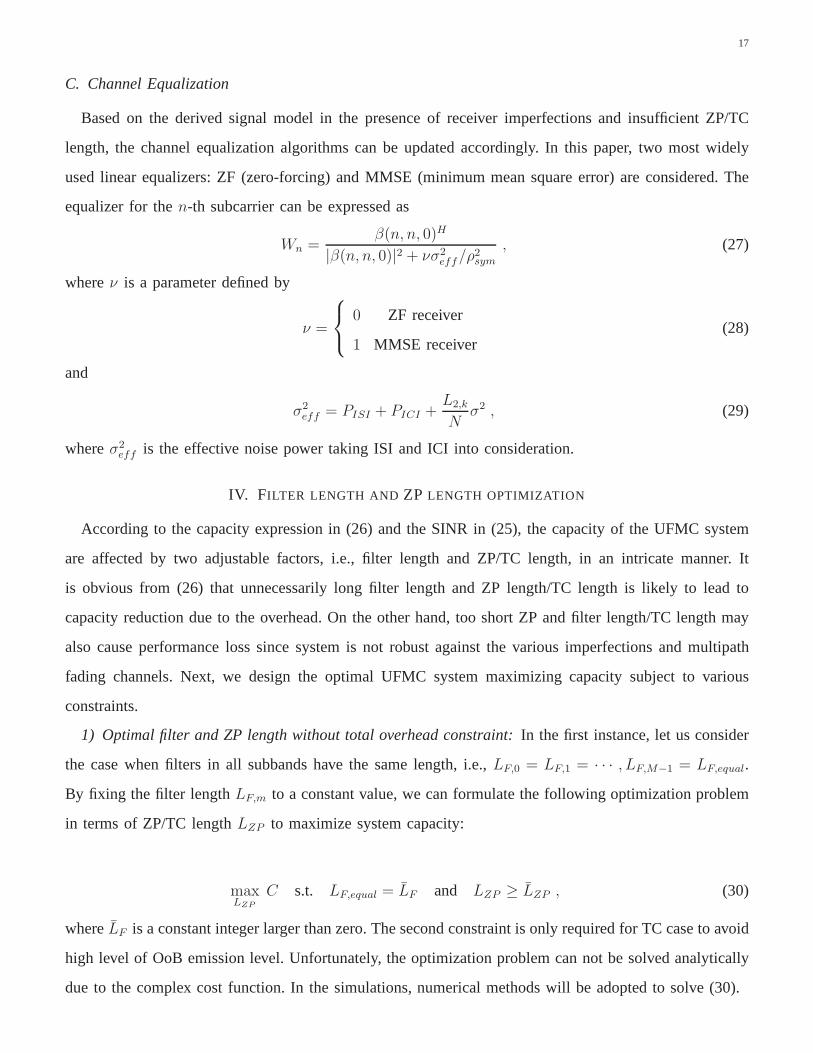
The analytical (in equation (22)) and simulated output SINRfor both UFMC and OFDM systems are
shown in Fig. 6 for input SNR = 15 dB (i.e.,σ2 = −15 dB). It is observed that UFMC exhibits large
SINR variation along the subcarriers in each subband in the error free case, while OFDM system shows
a relatively flat line in ideal case. However, this is changeddue to receiver errors and insufficient ZP, as
we can see that UFMC outperforms OFDM system for each subcarrier even for subcarriers at the edge
of subbands. This verifies that in the presence of insufficient ZP length and/or transceiver imperfections,
the subband filter in UFMC system can improve the performanceas compared to OFDM system.

21
0 5 10 15 20 25 30 35−3
−2.5
−2
−1.5
−1
−0.5
0
0.5
Subcarrier Index: n
PD
(dB
)
UFMC SimulatedUFMC AnalyticalOFDM SimulatedOFDM AnalyticalUFMC (Ideal case)OFDM (Ideal case)
Fig. 4. Desired signal power versus subcarrier index for both ideal and interference cases.
0 5 10 15 20 25 30 35−26
−24
−22
−20
−18
−16
−14
−12
−10
−8
Subcarrier Index: n
Pow
er (
dB)
UFMC Simulated PICI
UFMC Simulated PISI
UFMC Analytical PICI
UFMC Analytical PISI
OFDM Simulated PICI
OFDM Simulated PISI
OFDM Analytical PICI
OFDM Analytical PISI
Fig. 5. ICI and ISI power versus subcarrier index for both ideal and interference cases.
B. Optimizations
Next, we examine the optimization problems formulated in (30), (31), (32) and (33) by comparing
with the simulation results considering various parameters. To simplify the analysis, we will use the same
channel (ETU channel for all cases) and values of CFO and TO for all of the three users. Unless specified
otherwise, all of the parameters remain the same as in the previous simulation in Section V-A.
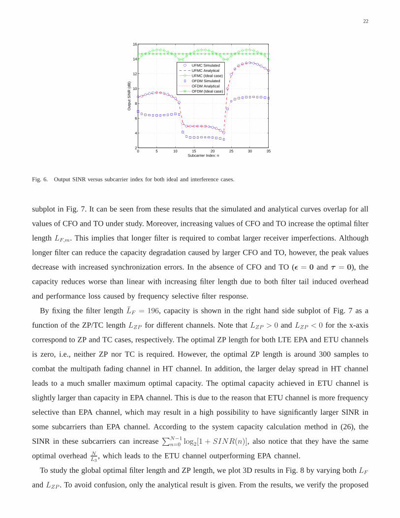
Let us first consider the optimization (31) with fixed ZP length LZP = 0. In order to show the impact
of filter length on the system performance and the optimal solutions and its relationship with the error
level, the capacity is plotted versus the filter length for different values ofǫ andτ in the left hand side
22
0 5 10 15 20 25 30 352
4
6
8
10
12
14
16
Subcarrier Index: n
Out
put S
INR
(dB
)
UFMC Simulated UFMC Analytical UFMC (Ideal case)OFDM Simulated OFDM Analytical OFDM (Ideal case)
Fig. 6. Output SINR versus subcarrier index for both ideal and interference cases.
subplot in Fig. 7. It can be seen from these results that the simulated and analytical curves overlap for all
values of CFO and TO under study. Moreover, increasing values of CFO and TO increase the optimal filter
lengthLF,m. This implies that longer filter is required to combat largerreceiver imperfections. Although
longer filter can reduce the capacity degradation caused by larger CFO and TO, however, the peak values
decrease with increased synchronization errors. In the absence of CFO and TO (ǫ = 0 andτ = 0), the
capacity reduces worse than linear with increasing filter length due to both filter tail induced overhead
and performance loss caused by frequency selective filter response.
By fixing the filter lengthLF = 196, capacity is shown in the right hand side subplot of Fig. 7 as a
function of the ZP/TC lengthLZP for different channels. Note thatLZP > 0 andLZP < 0 for the x-axis
correspond to ZP and TC cases, respectively. The optimal ZP length for both LTE EPA and ETU channels
is zero, i.e., neither ZP nor TC is required. However, the optimal ZP length is around 300 samples to
combat the multipath fading channel in HT channel. In addition, the larger delay spread in HT channel
leads to a much smaller maximum optimal capacity. The optimal capacity achieved in ETU channel is
slightly larger than capacity in EPA channel. This is due to the reason that ETU channel is more frequency
selective than EPA channel, which may result in a high possibility to have significantly larger SINR in
some subcarriers than EPA channel. According to the system capacity calculation method in (26), the
SINR in these subcarriers can increase∑N−1
n=0 log2[1 + SINR(n)], also notice that they have the same
optimal overheadNL3
, which leads to the ETU channel outperforming EPA channel.
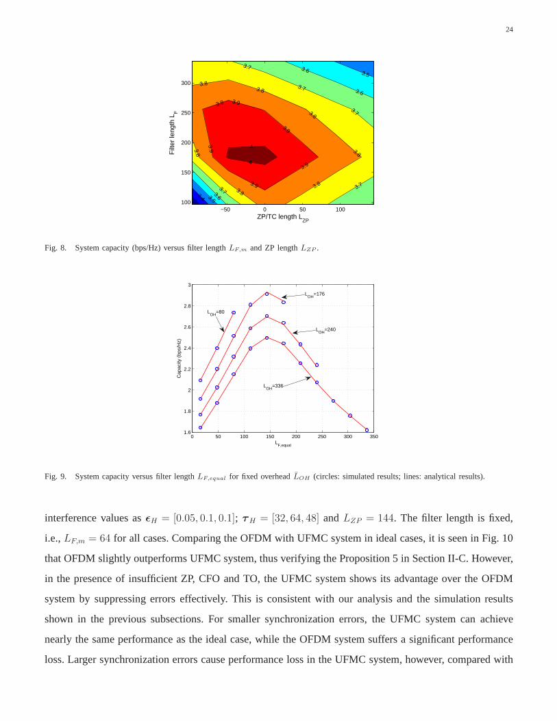
To study the global optimal filter length and ZP length, we plot 3D results in Fig. 8 by varying bothLF
andLZP . To avoid confusion, only the analytical result is given. From the results, we verify the proposed
23
0 100 200 300 400 5002
2.5
3
3.5
4
4.5
5
LF,equal
Cap
acity
(bp
s/H
z)
−200 0 200 400 6002.8
3
3.2
3.4
3.6
3.8
4
4.2
LZP
Cap
acity
(bp
s/H
z)
ITU HT channel
LTE EPA channel
ε=[0 0 0], τ=[0 0 0]
ε=[0.05 0.05 0.05], τ=[48 48 48]
ε=[0.07 0.07 0.07], τ=[80 80 80]
ε=[0.1 0.1 0.1], τ=[128 128 128]
LTE ETU channel
Fig. 7. System capacity versus filter length and ZP length (circles: simulated results; lines: analytical results), left: capacity versus filter
length; right: capacity versus ZP/TC length.
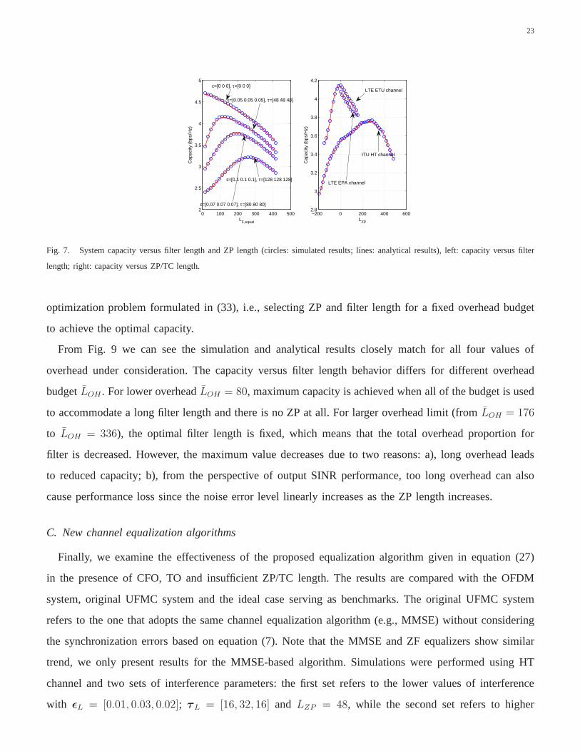
optimization problem formulated in (33), i.e., selecting ZP and filter length for a fixed overhead budget
to achieve the optimal capacity.
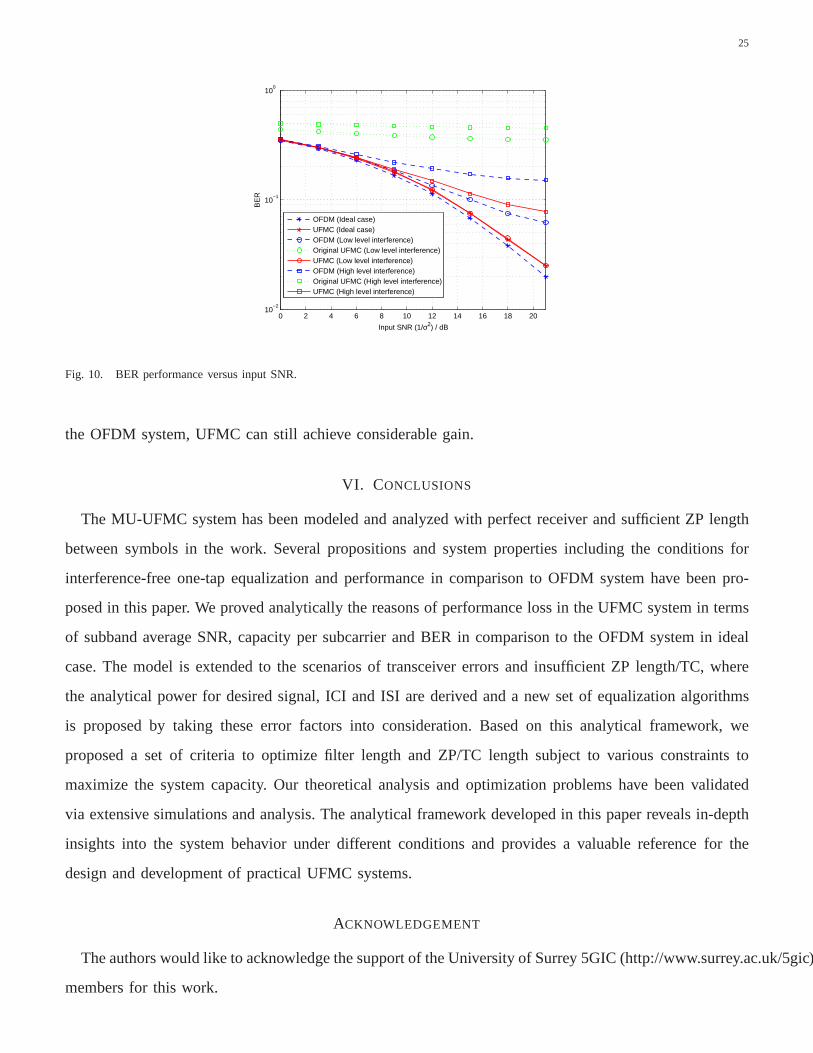
From Fig. 9 we can see the simulation and analytical results closely match for all four values of
overhead under consideration. The capacity versus filter length behavior differs for different overhead
budgetLOH . For lower overheadLOH = 80, maximum capacity is achieved when all of the budget is used
to accommodate a long filter length and there is no ZP at all. For larger overhead limit (fromLOH = 176
to LOH = 336), the optimal filter length is fixed, which means that the total overhead proportion for
filter is decreased. However, the maximum value decreases due to two reasons: a), long overhead leads
to reduced capacity; b), from the perspective of output SINRperformance, too long overhead can also
cause performance loss since the noise error level linearlyincreases as the ZP length increases.
C. New channel equalization algorithms
Finally, we examine the effectiveness of the proposed equalization algorithm given in equation (27)
in the presence of CFO, TO and insufficient ZP/TC length. The results are compared with the OFDM
system, original UFMC system and the ideal case serving as benchmarks. The original UFMC system
refers to the one that adopts the same channel equalization algorithm (e.g., MMSE) without considering
the synchronization errors based on equation (7). Note thatthe MMSE and ZF equalizers show similar
trend, we only present results for the MMSE-based algorithm. Simulations were performed using HT
channel and two sets of interference parameters: the first set refers to the lower values of interference
with ǫL = [0.01, 0.03, 0.02]; τL = [16, 32, 16] and LZP = 48, while the second set refers to higher
24
3.4
3.5
3.5
3.6
3.6
3.6
3.7
3.7
3.7
3.7 3.7
3.8
3.83.8
3.8
3.8
3.83.8
3.9
3.9
3.9
3.9
3.9
3.9
4
4
ZP/TC length LZP
Filt
er le
ngth
LF
−50 0 50 100100
150
200
250
300
Fig. 8. System capacity (bps/Hz) versus filter lengthLF,m and ZP lengthLZP .
0 50 100 150 200 250 300 3501.6
1.8
2
2.2
2.4
2.6
2.8
3
LF,equal
Cap
acity
(bp
s/H
z)
LOH
=80
LOH
=336
LOH
=240
LOH
=176
Fig. 9. System capacity versus filter lengthLF,equal for fixed overheadLOH (circles: simulated results; lines: analytical results).
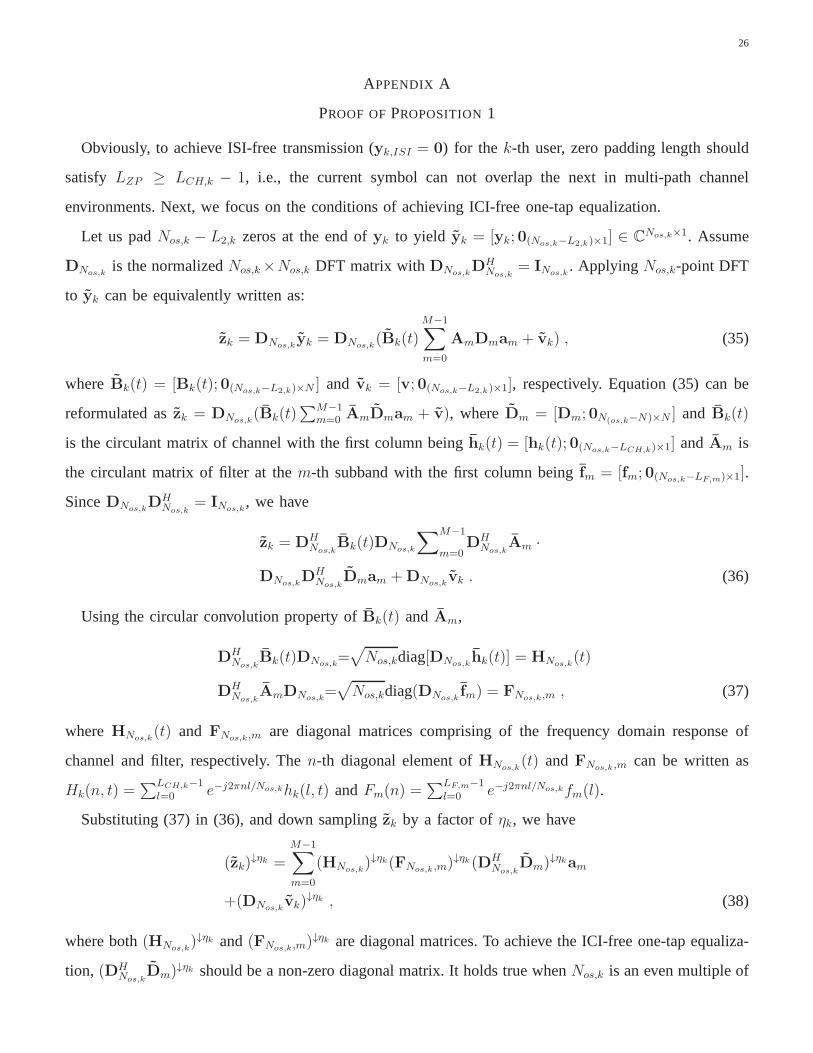
interference values asǫH = [0.05, 0.1, 0.1]; τH = [32, 64, 48] andLZP = 144. The filter length is fixed,
i.e.,LF,m = 64 for all cases. Comparing the OFDM with UFMC system in ideal cases, it is seen in Fig. 10
that OFDM slightly outperforms UFMC system, thus verifyingthe Proposition 5 in Section II-C. However,
in the presence of insufficient ZP, CFO and TO, the UFMC systemshows its advantage over the OFDM
system by suppressing errors effectively. This is consistent with our analysis and the simulation results
shown in the previous subsections. For smaller synchronization errors, the UFMC system can achieve
nearly the same performance as the ideal case, while the OFDMsystem suffers a significant performance
loss. Larger synchronization errors cause performance loss in the UFMC system, however, compared with
25
0 2 4 6 8 10 12 14 16 18 2010
−2
10−1
100
Input SNR (1/σ2) / dB
BE
R
OFDM (Ideal case)UFMC (Ideal case)OFDM (Low level interference) Original UFMC (Low level interference)UFMC (Low level interference)OFDM (High level interference)Original UFMC (High level interference)UFMC (High level interference)
Fig. 10. BER performance versus input SNR.
the OFDM system, UFMC can still achieve considerable gain.
VI. CONCLUSIONS
The MU-UFMC system has been modeled and analyzed with perfect receiver and sufficient ZP length
between symbols in the work. Several propositions and system properties including the conditions for
interference-free one-tap equalization and performance in comparison to OFDM system have been pro-
posed in this paper. We proved analytically the reasons of performance loss in the UFMC system in terms
of subband average SNR, capacity per subcarrier and BER in comparison to the OFDM system in ideal
case. The model is extended to the scenarios of transceiver errors and insufficient ZP length/TC, where
the analytical power for desired signal, ICI and ISI are derived and a new set of equalization algorithms
is proposed by taking these error factors into consideration. Based on this analytical framework, we
proposed a set of criteria to optimize filter length and ZP/TClength subject to various constraints to
maximize the system capacity. Our theoretical analysis andoptimization problems have been validated
via extensive simulations and analysis. The analytical framework developed in this paper reveals in-depth
insights into the system behavior under different conditions and provides a valuable reference for the
design and development of practical UFMC systems.
ACKNOWLEDGEMENT
The authors would like to acknowledge the support of the University of Surrey 5GIC (http://www.surrey.ac.uk/5gic)
members for this work.
26
APPENDIX A
PROOF OFPROPOSITION1
Obviously, to achieve ISI-free transmission (yk,ISI = 0) for the k-th user, zero padding length should
satisfy LZP ≥ LCH,k − 1, i.e., the current symbol can not overlap the next in multi-path channel
environments. Next, we focus on the conditions of achievingICI-free one-tap equalization.
Let us padNos,k − L2,k zeros at the end ofyk to yield yk = [yk; 0(Nos,k−L2,k)×1] ∈ CNos,k×1. Assume
DNos,kis the normalizedNos,k×Nos,k DFT matrix withDNos,k
DHNos,k
= INos,k. Applying Nos,k-point DFT
to yk can be equivalently written as:
zk = DNos,kyk = DNos,k
(Bk(t)
M−1∑
m=0
AmDmam + vk) , (35)
where Bk(t) = [Bk(t); 0(Nos,k−L2,k)×N ] and vk = [v; 0(Nos,k−L2,k)×1], respectively. Equation (35) can be
reformulated aszk = DNos,k(Bk(t)
∑M−1m=0 AmDmam + v), whereDm = [Dm; 0N(os,k−N)×N ] and Bk(t)
is the circulant matrix of channel with the first column beinghk(t) = [hk(t); 0(Nos,k−LCH,k)×1] andAm is
the circulant matrix of filter at them-th subband with the first column beingfm = [fm; 0(Nos,k−LF,m)×1].
SinceDNos,kDH
Nos,k= INos,k
, we have
zk = DHNos,k
Bk(t)DNos,k
∑M−1
m=0DH
Nos,kAm ·
DNos,kDH
Nos,kDmam +DNos,k
vk . (36)
Using the circular convolution property ofBk(t) andAm,
DHNos,k
Bk(t)DNos,k=√
Nos,kdiag[DNos,khk(t)] = HNos,k
(t)
DHNos,k
AmDNos,k=√
Nos,kdiag(DNos,kfm) = FNos,k,m , (37)
whereHNos,k(t) and FNos,k,m are diagonal matrices comprising of the frequency domain response of
channel and filter, respectively. Then-th diagonal element ofHNos,k(t) andFNos,k ,m can be written as
Hk(n, t) =∑LCH,k−1
l=0 e−j2πnl/Nos,khk(l, t) andFm(n) =∑LF,m−1
l=0 e−j2πnl/Nos,kfm(l).
Substituting (37) in (36), and down samplingzk by a factor ofηk, we have
(zk)↓ηk =
M−1∑
m=0
(HNos,k)↓ηk(FNos,k ,m)
↓ηk(DHNos,k
Dm)↓ηkam
+(DNos,kvk)
↓ηk , (38)
where both(HNos,k)↓ηk and(FNos,k,m)
↓ηk are diagonal matrices. To achieve the ICI-free one-tap equaliza-
tion, (DHNos,k
Dm)↓ηk should be a non-zero diagonal matrix. It holds true whenNos,k is an even multiple of

27
N , i.e.,Nos,k = 2ηkN , ηk ∈ R+, and in this case(DHNos,k
Dm)↓ηk = 1√
2ηkI. Combining with the inequality
Nos,k ≥ L2,k, we haveηk ≥ ⌈log2(L2,k
N)⌉. For the noise, then-th element of(DNos,k
v)↓ηk can be expressed
asvos,k(n) =∑L2,k
l=01√Nos,k
e−j2πnl/Nvk(l). Then-th diagonal element of(HNos,k)↓ηk and(FNos,k,m)
↓ηk can
be written asHk(n, t) =∑LCH,k
l=0 e−j2πnl/Nhk(l, t) and Fm(n) =∑LF,m
l=0 e−j2πnl/Nfm(l). Substitute into
(38), we obtainz(n) as given in (7), where 1ρm
√2ηk
Hk(n, t)Fm(n) andvos,k(n) are scalar coefficients and
processed noise. Both are independent of the modulated symbolsa(n) for n ∈ Um. Thus, interference-free
one-tap equalization can be performed.
APPENDIX B
PROOF OFPROPOSITION3
For normalized filter in them-th subband, we have|Fm(0)|2+ |Fm(1)|2+ · · ·+ |Fm(LF,m−1)|2 = Nm.
Using (8), we obtainSNRm = 1Nm
E{∑
n∈UmSNR(n)} = 1
Nm
NL2,kρ2m
ρ2CH,k · ρ2symσ2
∑
n∈Um|Fm(n)|2 =
NL2,kρ2m
ρ2CH,k ·ρ2symσ2 . Whereas, the SNR for OFDM system is independent of the subcarrier index and is
determined asSNRofdm = NL2,k
ρ2CH,k ·ρ2symσ2 .
Comparing SNR expression of UFMC to OFDM, the only difference is the normalization factorρ2m =
1Nm
trace(DHmA
HmAmDm). To prove the performance loss, let us first defineρ2B = 1
Nmtrace(DHAH
mAmD) =
1Nm
trace(AmAHm) =
NNm
with D being normalizedN-point DFT matrix.ρ2B can be also defined asρ2B =∑N−1
i=01
Nmtrace(Amdid
Hi A
Hm) with di being thei-th column ofD. Thenρ2B = 1
Nm
∑Ni=1 trace(DH
Nos,kAm
DNos,kDH
Nos,kdid
Hi DNos,k
DHNos,k
AHmDNos,k
) = 1Nm
trace(|(FNos,k,m)|2˜Di) = 1
Nm|(FNos,k,m)|2diag[ ˜Di] with
˜Di = DH
Nos,kdHi diDNos,k
. To simplify the analysis, let us define thei-th diagonal elements of˜Di as ˜di(l),
thenρ2B = 1Nm
∑Nos,k−1
l=0 |Fm(l)|2 ˜di(l). Let us defineρ2B,ds =1
Nm
∑⌊(Nos,k−1)/2ηk ⌋l=0 |Fm(l · 2ηk)|2 ˜di(l · 2ηk). It
is easy to getρ2B,ds =NNm
12ηk
andρ2B,ot = ρ2B − ρ2B,ds =NNm
[1− 12ηk
]. Similarly, for them-th subband, we
can writeρ2m =∑
i∈Um
1Nm
trace(AmdidHi A
Hm) = ρ2m,ds + ρ2m,ot with ρ2m,ds =
1Nm
12ηk
Nm = 12ηk
. According
to the property of the filter, the majority power is at the diagonal elements ofFNos,k,m which belong to the
m-th subband. Similarly, trace( ˜D) = Nm and also the majority power is at the same location, which means
that the subcarriers which belong to them-th subband contribute more power toρ2m than others, results
in ρ2m,ot ≥ (N − N2ηk
) 1N
andρ2m = ρ2m,ds + ρ2m,ot ≥ 1, i.e., 1ρ2m
≥ 1. i.e.,SNRm ≤ NL2,max
2
σ2 = SNRofdmm.
APPENDIX C
PROOF OFPROPOSITION4
In high-SNR region, average capacity per subcarrier can be approximated asCm ≈ 1Nm
∑
n∈Um
E(log2[SNR(n)]). Using the SNR expression in (8), we haveCm ≈ 1Nm
E(∑
n∈Umlog2[α1/ρ
2m|Hk(n, t)|2

28
|Fm(n)|2])
= 1Nm
E(
log2[(α1/ρ2m)
NmΠn∈Um|Hk(n, t)|2|Fm(n)|2]
)
. Since it is assumed that the subband is
narrow enough so that the subcarriers lie in the coherence bandwidth,Cm ≈ 1Nm
E(
log2[(α1/ρ2m|Hk(i, t)|2)Nm
|Πn∈UmFm(n)|2]
)
, wherei ∈ Um. Using inequality of arithmetic and geometric means [25] (pp20, Chapter
2), we have|Πn∈UmFm(n)|2 ≤ ( 1
Nm
∑
n∈Um|Fm(n)|2)Nm = ( 1
NmNm)
Nm = 1. ThenCm ≤ 1Nm
E(
log2[
(α1/ρ2m|Hk(i, t)|2 1Nm
)Nm ])
= E(log2[α1/ρ2m|Hk(i, t)|2)]. As shown in Appendix B,ρ2m ≥ 1, therefore,
Cm ≤ E(
log2[α|Hk(i, t)|2])
= Cofdm.
APPENDIX D
PROOF OFPROPOSITION5
Using (12) and (13), we haveBER(n) = 1e−φ1SNR(n) + 1e
−φ2SNR(n), where1 = 16(1 − 1√
Mmod)
and 2 = 13(1 − 1√
Mmod). Then the average BER in them-th subband can be given asBERm =
1Nm
E[∑
n∈UmBER(n)
]
= 1Nm
E(
1
∑
n∈Ume−φ1SNR(n)+2
∑
n∈Ume−φ2SNR(n)
)
. Let us consider the two
expressions one-by-one. Using inequality of arithmetic and geometric means [25] (pp20, Chapter 2), we
have 1Nm
∑
n∈Ume−φ1SNR(n) ≥ (Πn∈Um
e−φ1SNR(n))1/Nm = e−φ11/Nm∑
n∈UmSNRm(n). Using the SINR equa-
tion in (8), we obtaine−φ11/Nm
∑n∈Um
SNRm(n) ≈ e−φ11/Nm|Hk(i,t)|2∑
n∈Umα1/ρ2m|Fm(n)|2 = e−φ1|Hk(i,t)|2α1/ρ2m .
Since bothφ1 andNm are positive values,ρ2m ≥ 1 and according to Proposition 2, it is trivial to obtain
e−φ1|Hk(i,t)|2α1/ρ2m ≥ e−φ1|Hk(i,t)|2α.
REFERENCES
[1] 5GNOW, “D3.2: 5G waveform candidate selection,” Tech. Rep., 2014.
[2] G. Wunder, P. Jung, M. Kasparick, T. Wild, F. Schaich, Y. Chen, S. Brink, I. Gaspar, N. Michailow, A. Festag, L. Mendes,N. Cassiau,
D. Ktenas, M. Dryjanski, S. Pietrzyk, B. Eged, P. Vago, and F.Wiedmann, “5GNOW: non-orthogonal, asynchronous waveforms for
future mobile applications,”IEEE Communications Magazine, vol. 52, no. 2, pp. 97–105, February 2014.
[3] V. Vakilian, T. Wild, F. Schaich, S. Ten Brink, and J.-F. Frigon, “Universal-filtered multi-carrier technique for wireless systems beyond
LTE,” in IEEE Globecom Workshops (GC Wkshps), 2013, pp. 223–228.
[4] Y. Chen, F. Schaich, and T. Wild, “Multiple access and waveforms for 5G: IDMA and universal filtered multi-carrier,” in IEEE Vehicular
Technology Conference (VTC Spring), 2014, pp. 1–5.
[5] F. Schaich and T. Wild, “Waveform contenders for 5G; OFDMvs. FBMC vs. UFMC,” inInternational Symposium on Communications,
Control and Signal Processing (ISCCSP), May 2014, pp. 457–460.
[6] J. Li, E. Bala, and R. Yang, “Resource block filtered-OFDMfor future spectrally agile and power efficient systems,”Physical
Communication, vol. 11, pp. 36–55, 2014.
[7] B. Farhang-Boroujeny, “OFDM versus filter bank multicarrier,” IEEE Signal Processing Magazine, vol. 28, no. 3, pp. 92–112, May
2011.
[8] J. Du, P. Xiao, J. Wu, and Q. Chen, “Design of isotropic orthogonal transform algorithm-based multicarrier systems with blind channel
estimation,”IET Communications, vol. 6, pp. 2695–2704, November 2012.
[9] E. Dahlman, S. Parkvall, and J. Skold,4G: LTE/LTE-Advanced for Mobile Broadband. Academic Press, 2011.
29
[10] D. S. Sesia, M. M. Baker, and M. I. Toufik,LTE: The UMTS Long Term Evolution: from Theory to Practice, 2nd ed. Wiley-Blackwell,
2011.
[11] X. Wang, T. Wild, F. Schaich, and A. Fonseca dos Santos, “Universal filtered multi-carrier with leakage-based filteroptimization,” in
European Wireless Conference, 2014, pp. 1–5.
[12] S. Mirabbasi and K. Martin, “Overlapped complex-modulated transmultiplexer filters with simplified design and superior stopbands,”
IEEE Transactions on Circuits and Systems II: Analog and Digital Signal Processing, vol. 50, no. 8, pp. 456–469, 2003.
[13] D. Chen, D. Qu, T. Jiang, and Y. He, “Prototype filter optimization to minimize stopband energy with NPR constraint for filter bank
multicarrier modulation systems,”IEEE Transactions on Signal Processing, vol. 61, no. 1, pp. 159–169, 2013.
[14] P. Xiao, C. Toal, D. Burns, V. Fusco, and C. Cowan, “Transmit and receive filter design for OFDM based WLAN systems,” inIEEE
International Conference on Wireless Communications and Signal Processing (WCSP), 2010, pp. 1–4.
[15] D. Noguet, M. Gautier, and V. Berg, “Advances in opportunistic radio technologies for tvws,”EURASIP Journal on Wireless
Communications and Networking, vol. 2011, no. 1, pp. 1–12, 2011.
[16] F. Schaich and T. Wild, “Relaxed synchronization support of universal filtered multi-carrier including autonomous timing advance,” in
International Symposium on Wireless Communications Systems (ISWCS), 2014, pp. 203–208.
[17] A. Farhang, N. Marchetti, F. Figueiredo, and J. P. Miranda, “Massive MIMO and waveform design for 5th generation wireless
communication systems,” inInternational Conference on 5G for Ubiquitous Connectivity (5GU), 2014, pp. 70–75.
[18] H. Steendam and M. Moeneclaey, “Analysis and optimization of the performance of OFDM on frequency-selective time-selective fading
channels,”IEEE Transactions on Communications, vol. 47, no. 12, pp. 1811–1819, 1999.
[19] Y. Huang and B. D. Rao, “Awareness of channel statisticsfor slow cyclic prefix adaptation in an OFDMA system,”IEEE Wireless
Communications Letters, vol. 1, no. 4, pp. 332–335, 2012.
[20] X. Wang, T. Wild, and F. Schaich, “Filter optimization for carrier-frequency-and timing-offset in universal filtered multi-carrier systems,”
in IEEE Vehicular Technology Conference (VTC Spring), 2015, pp. 1–6.
[21] T. Van Waterschoot, V. Le Nir, J. Duplicy, and M. Moonen,“Analytical expressions for the power spectral density of CP-OFDM and
ZP-OFDM signals,”IEEE Signal Processing Letters, vol. 17, no. 4, pp. 371–374, 2010.
[22] D. Chen, X.-G. Xia, T. Jiang, and X. Gao, “Properties andpower spectral densities of CP based OQAM-OFDM systems,”IEEE
Transactions on Signal Processing, vol. 63, no. 14, pp. 3561–3575, 2015.
[23] B. Muquet, Z. Wang, G. B. Giannakis, M. De Courville, andP. Duhamel, “Cyclic prefixing or zero padding for wireless multicarrier
transmissions?”Communications, IEEE Transactions on, vol. 50, no. 12, pp. 2136–2148, 2002.
[24] N. Kim, Y. Lee, and H. Park, “Performance analysis of MIMO system with linear MMSE receiver,”IEEE Transactions on Wireless
Communications, vol. 7, no. 11, pp. 4474–4478, 2008.
[25] J. M. Steels,The Cauchy-Schwarz Master Class: An Introduction to the Artof Mathematical Inequalities. Cambridge University
Press, 2004.