Embed Size (px)
Citation preview
SERVICE MANUAL
CONTENTS
1. TECHNICAL CHANGES ····································22. PART NAMES AND FUNCTIONS······················33. SPECIFICATION·················································44. OUTLINES AND DIMENSIONS ·························55. WIRING DIAGRAM ············································86. REFRIGERANT SYSTEM DIAGRAM················97. PERFORMANCE CURVES······························128. TROUBLESHOOTING······································159. DISASSEMBLY INSTRUCTIONS ····················17
10. PARTS LIST······················································2511. RoHS PARTS LIST···········································2912. OPTIONAL PARTS···········································33
Wireless typeModels
SPLIT-TYPE, AIR CONDITIONERS
MU-A08ND-MU-A08ND-MU-A10ND-MU-A10ND-MU-A12ND-MU-A15ND-MU-A15ND- C2
C1
C1
C2
C1
C2
C1
MU-A10NDMU-A12ND
TM
Revision:B• MU-A10ND - has been added.• RoHS PARTS LIST has been added.
C2
Please void OB403 REVISED EDITION-A.
NOTE:This service manual describes technical data of outdoor units.RoHS compliant products have <G> mark on the spec name plate.For servicing of RoHS compliant products, refer to the RoHS Parts List.
OUTDOOR UNIT
Indoor unit service manualMS-A•ND Series (OB402)
No. OB403REVISED EDITION-B
OB403B--1.qxp 07.6.26 10:28 AM Page 1
2
TECHNICAL CHANGES1
MU-09SN - ➔ MU-A08ND -1. Compressor has been changed. (RH-130NGDT ➔ 2R10S3R236A-6B)2. Outdoor fan motor has been changed. (RA6N23-AA ➔ RA6N33-AA)3. Compressor capacitor has been changed.4. Outdoor fan motor capacitor has been changed.
MU-10SN - ➔ MU-A10ND -1. Outdoor unit model has been changed.
•Valve cover has been added.•Dimension has been changed. (780Wo540Ho255D ➔ 800Wo550Ho285D)
2. Compressor has been changed. (RH145NGCT ➔ RH145NHNT)3. Outdoor fan motor has been changed. (RA6N33-AA ➔ RA6N21-AB)4. Compressor capacitor has been changed.5. Outdoor fan motor capacitor has been changed.6. Outdoor heat exchanger has been changed. ([9.52 L-Bend ➔ [7 Flat)
MU-12SN - ➔ MU-A12ND -1. Outdoor unit model has been changed.
•Valve cover has been added.•Dimension has been changed. (780Wo540Ho255D ➔ 800Wo550Ho285D)
2. Compressor has been changed. (RH167NHDT ➔ RH174NHNT)3. Outdoor fan motor has been changed. (RA6N33-AA ➔ RA6N30-BA)4. Compressor capacitor has been changed.5. Outdoor fan motor capacitor has been changed.6. Outdoor heat exchanger has been changed. ([9.52 L-Bend ➔ [7 Flat)
MU-15SN - ➔ MU-A15ND -1. Compressor has been changed. (RH-207NHDT ➔ RH207NRAT)2. Outdoor fan motor has been changed. (RN6N50-BA ➔ RA6V60-MA)3. Compressor capacitor has been changed.4. Outdoor fan motor capacitor has been changed.
MU-A08ND - ➔ MU-A08ND -MU-A15ND - ➔ MU-A15ND -1. Valve cover has been added.
MU-A10ND - ➔ MU-A10ND -1. Outdoor heat exchanger has been changed.2. Capillary tube has been changed.
C2C1
C2C1
C2C1
C1C2
C1C2
C1C2
C1C2
Revision A:• MU-A08ND - and MU-A15ND - have been added.C2C2
Revision B:• MU-A10ND - has been added. • RoHS PARTS LIST has been added.
C2
OB403B--1.qxp 07.6.26 10:28 AM Page 2
3
PART NAMES AND FUNCTIONS2
OUTDOOR UNIT
MU-A08ND
MU-A15ND
Air inlet
Piping
Drain hose
Air outlet
Drain outlet
(back and side)
MU-A10NDMU-A12ND
Air inlet
Piping
Drain hose
Air outlet
Drain outlet
back and side : MU-A10ND back : MU-A12ND( )
Air inlet
Piping
Drain hose
Air outlet
Drain outlet
(back and side)
OB403B--1.qxp 07.6.26 10:28 AM Page 3
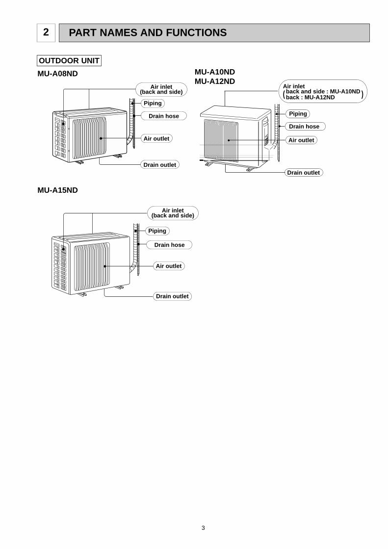
SPECIFICATION
4
3
Outdoor model
Function
Power supply
Coefficient of performance (C.O.P)
CapacityDehumidificationAir flowStarting currentCompressor motor currentFan motor current
ModelOutputWindingresistance (at 20:)ModelWindingresistance (at 20:)Dimensions WOHODWeightSound levelFan speedFan speed regulatorRefrigerant filling capacity (R22)Refrigeration oil (Model)
kWR/hK /h
AAA
W
"
"
mmkgdBrpm
kg
cc
MU-A15ND
4.01.8
228035
5.620.5
2.97RH207NRAT
1000C-R 1.50C-S 2.33
RA6V60-MAWHT-BLK 116 BLK-RED 111 850o605o290
4252
865
1.6
520 (MS56)
Ele
ctric
alda
taF
an
mot
orS
peci
alre
mar
ksC
ompr
esso
rC
apac
ity
MU-A08ND
2.20.5
165619
2.390.363.44
2R10S3R236A-6B470
C-R 4.09C-S 5.58
RA6N33-AAWHT-BLK 150BLK-RED 265780o540o255
2845
700
0.8
260 (ATM0S M60)
MU-A10ND
2.91.2
189626
3.860.263.12
RH145NHNT700
C-R 2.74C-S 3.78
RA6N21-ABWHT-BLK 384 BLK-RED 259
3246
820
0.61.1
300 (MS56)
1
MU-A12ND
3.61.7
188430
4.950.353.08
RH174NHNT800
C-R 2.19C-S 3.3
RA6N30-BAWHT-BLK 312BLK-RED 255
3447
850
1.2
520 (MS56)
CoolingSingle phase
220-230V, 60Hz
800o550o285
C1
C2
NOTE: Test conditions are based on CNS14464, ISO5151. Cooling : Indoor DB27°C / WB19°C
Outdoor DB35°C / WB24°CIndoor-Outdoor piping length: 5 m
OB403B--1.qxp 07.6.26 10:28 AM Page 4
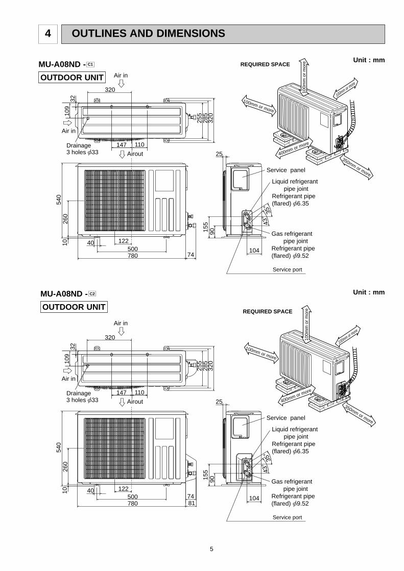
320
25
43-
35-
104
320
285
255
Service panel
Gas refrigerant pipe jointRefrigerant pipe(flared) [9.52
Liquid refrigerant pipe jointRefrigerant pipe(flared) [6.35
Airout
Air in
Air in
Service port
155
90
74
260
10
780500
12240
540
109
32
110147Drainage 3 holes [33
5
OUTLINES AND DIMENSIONS4
Unit : mm
100m
m o
r m
ore
100mm or more
100mm or more
350mm or more
REQUIRED SPACE
400mm or more
OUTDOOR UNIT
MU-A08ND - C1
Unit : mm
OUTDOOR UNIT
MU-A08ND - C2
320
25
43-
35-
104
320
285
255
Service panel
Gas refrigerant pipe jointRefrigerant pipe(flared) [9.52
Liquid refrigerant pipe jointRefrigerant pipe(flared) [6.35
Airout
Air in
Air in
Service port
155
90
8174
260
10
780500
12240
540
109
32
110147Drainage 3 holes [33
100m
m o
r m
ore
100mm or more
100mm or more
350mm or more
REQUIRED SPACE
400mm or more
OB403B--1.qxp 07.6.26 10:28 AM Page 5
6
100mm or more
REQUIRED SPACE
350mm or more500mm or more
100m
m o
r m
ore
100mm or more
30 Service panel
Service port
605
292
20
50183
500850 74
157
100
161
Gas refrigerant pipe jointRefrigerant pipe (flared) [12.7
Liquid refrigerant pipe jointRefrigerant pipe (flared) [6.35 30o
35o
Drainage3 holes [33
Air out
Air in
Air in
248
35
350
50
290
310
345
20355
90
Drainagehole [16.2
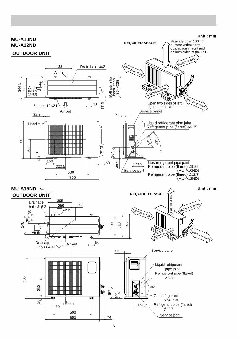
MU-A15ND - C1 Unit : mm
Unit : mm
OUTDOOR UNIT
MU-A10ND MU-A12ND
43-
35-
10
69
800
302.5
500
150
22.3
Handle
550
280
164.
599
.5 170.5
23Service panel
Service port
285
344.
5 44
400
Air in
Air out
Air in(MU-A10ND)
17.5
Bol
t pitc
h fo
rin
stal
latio
n30
4~32
5
40
Liquid refrigerant pipe jointRefrigerant pipe (flared) [6.35
Gas refrigerant pipe jointRefrigerant pipe (flared) [9.52 (MU-A10ND) Refrigerant pipe (flared) [12.7 (MU-A12ND)
2 holes 10X21
Basically open 100mm or more without any obstruction in front andon both sides of the unit.
350mm or more
200mm or more
100mm or more
100mm or more
Open two sides of left, right, or rear side.
Drain hole [42
REQUIRED SPACE
OUTDOOR UNIT
OB403B--1.qxp 07.6.26 10:28 AM Page 6
7
Unit : mm
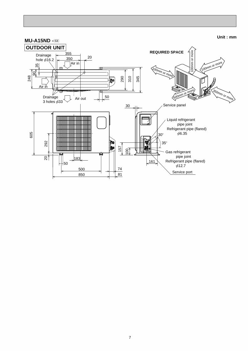
OUTDOOR UNITMU-A15ND - C2
30 Service panel
Service port
605
292
20
50183
500850 81
74
157
100
161
Gas refrigerant pipe jointRefrigerant pipe (flared) [12.7
Liquid refrigerant pipe jointRefrigerant pipe (flared) [6.35 30o
35o
Drainage3 holes [33
Air out
Air in
Air in
248
35
350
50
290
310
345
20355
90
Drainagehole [16.2
100mm or more
REQUIRED SPACE
350mm or more500mm or more
100m
m o
r m
ore
100mm or more
OB403B--1.qxp 07.6.26 10:28 AM Page 7
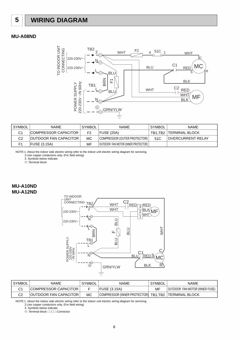
WIRING DIAGRAM
8
5
MU-A08ND
SYMBOL
C1
C2
F1
SYMBOL
F2
MC
MF
SYMBOL
TB1,TB2
51C
NAME NAME NAME
COMPRESSOR CAPACITOR
OUTDOOR FAN CAPACITOR
FUSE (3.15A)
FUSE (20A)
COMPRESSOR (OUTER PROTECTOR)
OUTDOOR FAN MOTOR (INNER PROTECTOR)
TERMINAL BLOCK
OVERCURRENT RELAY
NOTE:1. About the indoor side electric wiring refer to the indoor unit electric wiring diagram for servicing.2.Use copper conductors only. (For field wiring)3. Symbols below indicate./: Terminal block
TB1
TB2
GRN/YLW
N
L
2
N
L
MF
C2
C1
SRED MC
R
C
BLK
PO
WE
R S
UP
PLY
220-
230V
~/N
60H
z
CO
NN
EC
TIN
GT
O IN
DO
OR
UN
IT
BR
N
BLU
BLU
BLU
14 51CWHT WHT
BLKWHTREDWHT
F1
F2
220-230V~
220-230V~
MU-A10NDMU-A12ND
SYMBOL
C1
C2
SYMBOL
F
MC
SYMBOL
MF
TB1,TB2
NAME NAME NAME
COMPRESSOR CAPACITOR
OUTDOOR FAN CAPACITOR
FUSE (3.15A)
COMPRESSOR (INNER PROTECTOR)
OUTDOOR FAN MOTOR (INNER FUSE)
TERMINAL BLOCK
NOTE:1. About the indoor side electric wiring refer to the indoor unit electric wiring diagram for servicing.2.Use copper conductors only. (For field wiring)3. Symbols below indicate./: Terminal block :Connector
N
L
TB1
L
N
2
TB2 C2
220-230V~
C1
BLU
BLU
WH
T
WHT
RED
R
MCC
WHTCONNECTING
BLK
S
BLU
1
32 MF
WHTBLKRED
GRN/YLW
RED
PO
WE
R S
UP
PLY
220
-230
V ~
/N 6
0Hz
220-230V~
F
BR
N
BLU
TO INDOORUNIT
OB403B--1.qxp 07.6.26 10:28 AM Page 8
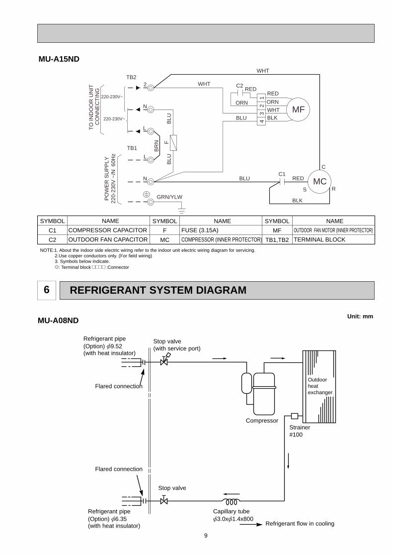
9
REFRIGERANT SYSTEM DIAGRAM6
Strainer#100
MU-A08ND
Refrigerant pipe(Option) [9.52(with heat insulator)
Outdoorheatexchanger
Capillary tube[3.0x[1.4x800
Refrigerant pipe(Option) [6.35(with heat insulator) Refrigerant flow in cooling
Unit: mm
Stop valve(with service port)
Compressor
Flared connection
Flared connection
Stop valve
MU-A15ND
SYMBOL
C1
C2
SYMBOL
F
MC
SYMBOL
MF
TB1,TB2
NAME NAME NAME
COMPRESSOR CAPACITOR
OUTDOOR FAN CAPACITOR
FUSE (3.15A)
COMPRESSOR (INNER PROTECTOR)
OUTDOOR FAN MOTOR (INNER PROTECTOR)
TERMINAL BLOCK
NOTE:1. About the indoor side electric wiring refer to the indoor unit electric wiring diagram for servicing.2.Use copper conductors only. (For field wiring)3. Symbols below indicate./: Terminal block :Connector
CO
NN
EC
TIN
GT
O IN
DO
OR
UN
IT
RS
2
N
L
TB2
RED
ORN
BLU
WHT
GRN/YLW
C2RED
MFBLK
4
WHT
ORN
32
1
WHT
BLK
L
N
TB1 BR
N
BLUC1
RED
C
MC
BLU
PO
WE
R S
UP
PLY
220-
230V
~/N
60H
z
FB
LU
220-230V~
220-230V~
OB403B--1.qxp 07.6.26 10:28 AM Page 9
10
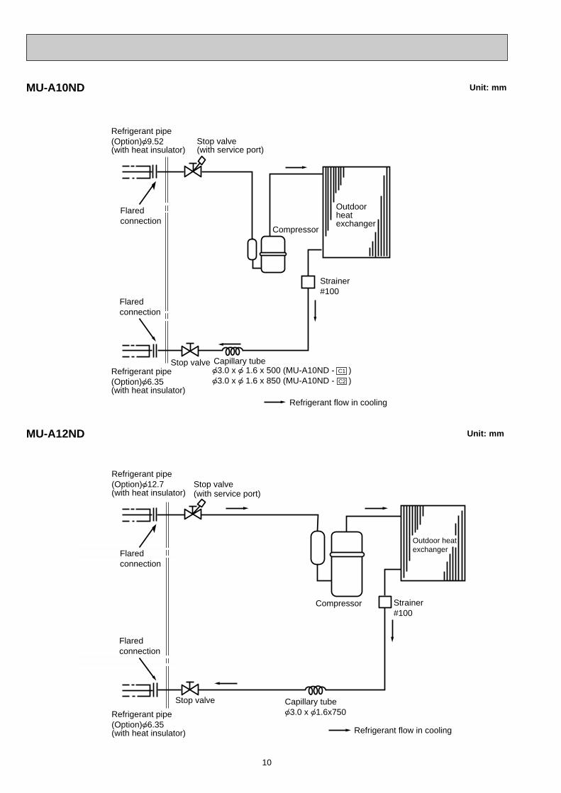
Capillary tube{3.0 x {1.6x750
Stop valve(with service port)
Stop valve
Compressor Strainer#100
Outdoor heatexchanger
Refrigerant flow in cooling
Refrigerant pipe(Option){6.35(with heat insulator)
Refrigerant pipe(Option){12.7(with heat insulator)
Flaredconnection
Flaredconnection
MU-A12ND Unit: mm
MU-A10ND
Refrigerant flow in cooling
Capillary tube{3.0 x { 1.6 x 500 (MU-A10ND - ){3.0 x { 1.6 x 850 (MU-A10ND - )
Compressor
Stop valve(with service port)
Stop valve
Strainer#100
Outdoor heatexchanger
C1
C2
Refrigerant pipe(Option){6.35(with heat insulator)
Refrigerant pipe(Option){9.52(with heat insulator)
Flaredconnection
Flaredconnection
Unit: mm
OB403B--1.qxp 07.6.26 10:28 AM Page 10
11
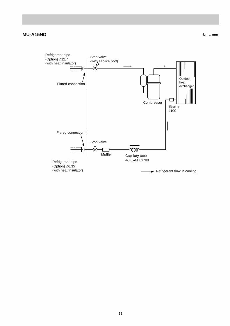
MU-A15ND Unit: mm
Strainer#100
Muffler
Refrigerant pipe(Option) [12.7(with heat insulator)
Outdoorheatexchanger
Capillary tube[3.0x[1.8x700Refrigerant pipe
(Option) [6.35(with heat insulator) Refrigerant flow in cooling
Stop valve(with service port)
Compressor
Flared connection
Flared connection
Stop valve
OB403B--1.qxp 07.6.26 10:28 AM Page 11
12
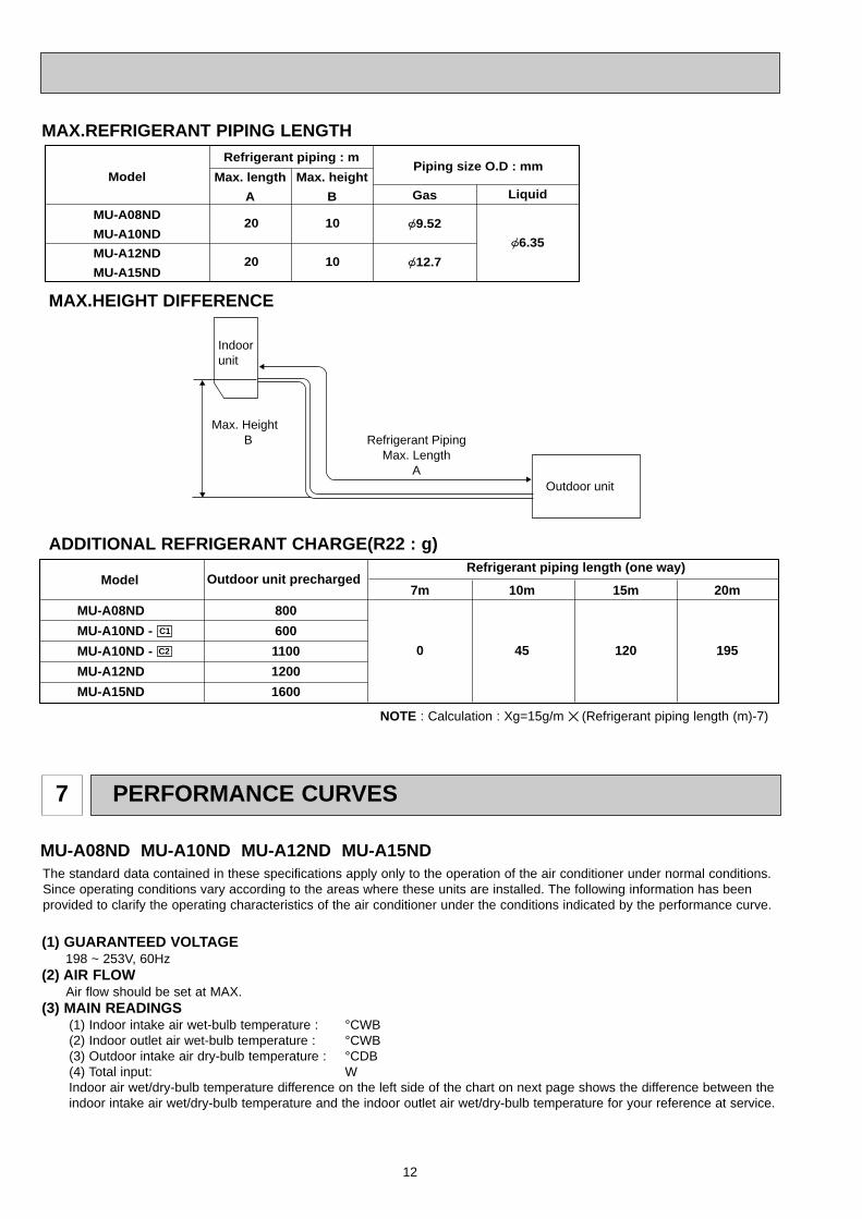
MAX.REFRIGERANT PIPING LENGTH
Model Piping size O.D : mm
Refrigerant piping : m
Gas
{9.52
{12.7
Liquid
{6.35
20
20
MU-A08ND
MU-A10ND
MU-A12ND
MU-A15ND
10
10
Max. length
A
Max. height
B
Indoor unit
Max. Height B
Outdoor unit
Refrigerant Piping Max. Length
A
MAX.HEIGHT DIFFERENCE
ADDITIONAL REFRIGERANT CHARGE(R22 : g)
NOTE : Calculation : Xg=15g/m ✕ (Refrigerant piping length (m)-7)
Model Outdoor unit precharged Refrigerant piping length (one way)
15m 20m
195
7m 10m
1200 45
MU-A08ND
MU-A10ND -
MU-A10ND -
MU-A12ND
MU-A15ND
800
600
1100
1200
1600
C1
C2
PERFORMANCE CURVES7
The standard data contained in these specifications apply only to the operation of the air conditioner under normal conditions.Since operating conditions vary according to the areas where these units are installed. The following information has beenprovided to clarify the operating characteristics of the air conditioner under the conditions indicated by the performance curve.
(1) GUARANTEED VOLTAGE198 ~ 253V, 60Hz
(2) AIR FLOWAir flow should be set at MAX.
(3) MAIN READINGS(1) Indoor intake air wet-bulb temperature : °CWB(2) Indoor outlet air wet-bulb temperature : °CWB(3) Outdoor intake air dry-bulb temperature : °CDB(4) Total input: WIndoor air wet/dry-bulb temperature difference on the left side of the chart on next page shows the difference between theindoor intake air wet/dry-bulb temperature and the indoor outlet air wet/dry-bulb temperature for your reference at service.
MU-A08ND MU-A10ND MU-A12ND MU-A15ND
OB403B--1.qxp 07.6.26 10:28 AM Page 12
13
1 Both indoor and outdoor units are under the same temperature/humidity condition.
OUTDOOR LOW PRESSURE AND OUTDOOR UNIT CURRENTCOOL operation
2 Air flow should be set at MAX.
Dry-bulb temperature (:) Relative humidity (%)
20 50
25 60
30 70
3 The unit of pressure has been changed to MPa on the international system of units(SI unit system).The conversion factor is : 1(MPa [Gauge]) =10.2(kgf/ff [Gauge])
Indoor intake air WB temperature (:)
Outdoor intake air DB temperature (:)
Indoor intake air WB temperature (:)
Outdoor intake air DB temperature (:)
MU
-A10
ND
MS
-A10
ND
MU
-A12
ND
MS
-A12
ND
MS
-A15
ND
MU
-A15
ND
4.8
4.3
5.4
7.0
6.5
5.9
MU
-A08
ND
5.4
4.8
6.0
7.9
7.3
6.6
7.5
6.7
8.4
11.2
10.2
9.3
8.5
7.5
9.5
12.8
11.6
10.5
MS
-A08
ND
Wet-and dry-bulbthermometers
Wet and dry-bulbthermometers
How to measure the indoor air wet/dry-bulb temperature difference1. Attach at least 2 sets of wet and-dry-bulb thermometers to the indoor air intake as shown in the figure, and at least 2 sets
of wet and dry-bulb thermometers to the indoor air outlet. The thermometers must be attached to the position where airspeed is high.
2. Attach at least 2 sets of wet and dry-bulb thermometers to the outdoor air intake.Cover the thermometers to prevent direct rays of the sun.
3. Check that the air filter is cleaned.4. Open windows and doors of the room.5. Press the EMERGENCY OPERATION switch once to start the EMERGENCY COOL MODE.6. When system stabilizes after more than 15 minutes, measure temperature and take an average temperature.7. 10 minutes later, measure temperature again and check that the temperature does not change.
INDOOR UNIT OUTDOOR UNIT
OB403B--1.qxp 07.6.26 10:28 AM Page 13
14
15 18 2050
2560
3070
35(:) (%)
1.5
2.0
2.5
3.0
3.5
32
220V
5
6
7
8
415 18 20
502560
3070
32 35(:) (%)
0.4
0.5
0.6
0.7
0.8220V
MU-A08ND MU-A08ND
Out
door
low
pre
ssur
e
Ambient temperature(˚C) Ambient humidity(%) Ambient temperature(˚C) Ambient humidity(%)
Out
door
uni
t cu
rren
t (A
)
(kgf/F[Gauge])(MPa[Gauge])
15 2050
2560
3070
35(:) (%)
0.3
0.4
0.5
0.6
0.77.0
6.0
5.0
4.0
3.0
220V
18 32 15 2050
18 322560
3070
35(:) (%)
3
4
5
6
220V
MU-A12ND MU-A12ND
Ambient temperature(˚C) Ambient humidity(%) Ambient temperature(˚C) Ambient humidity(%)
Out
door
low
pre
ssur
e
Out
door
uni
t cu
rren
t (A
)
(kgf/F[Gauge])(MPa[Gauge])
15 2050
2560
3070
35(:) (%)
2.0
2.5
3.0
3.5
4.0
220V
18 3215 2050
2560
3070
35(:) (%)
0.4
0.5
0.6
0.7
0.8
220V
4.0
5.0
6.0
7.0
8.0
9.00.9
18 32
MU-A10ND MU-A10ND
Out
door
low
pre
ssur
e
Ambient temperature(˚C) Ambient humidity(%) Ambient temperature(˚C) Ambient humidity(%)
Out
door
uni
t cu
rren
t (A
)
(kgf/F[Gauge])(MPa[Gauge])
15 3218 20 50
2560
30 70
35(:) (%)
0.3
0.4
0.5
0.6
0.7
4
5
6
7
3
220V
15 18 2050
2560
30 70
35(:) (%)
4.0
4.5
5.0
5.5
6.0
6.5
32
220V
MU-A15ND MU-A15ND
Ambient temperature(˚C) Ambient humidity(%) Ambient temperature(˚C) Ambient humidity(%)
Out
door
low
pre
ssur
e
Out
door
uni
t cu
rren
t (A
)
(kgf/F[Gauge])(MPa[Gauge])
OB403B--1.qxp 07.6.26 10:28 AM Page 14
15
TROUBLESHOOTING8
8-1. Cautions on troubleshooting1. Before troubleshooting, check the following:
1) Check the power supply voltage.2) Check the indoor/outdoor connecting wire for mis-wiring.
2. Take care the following during servicing.1).Before servicing the air conditioner, be sure to turn off the main unit first with the remote controller, and then after con-
firming the horizontal vane is closed, turn off the breaker and / or disconnect the power plug.2) Be sure to turn OFF the power supply before removing the front panel, the cabinet, the top panel and the electronic
control P.C. board.3) When removing the electronic control P.C. board, hold the edge of the
board with care NOT to apply stress on the components.4) When connecting or disconnecting the connectors, hold the housing of the
connector. DO NOT pull the lead wires.
Lead wiring Housing point
Start
Indoor unit operates.Outdoor unit doesn't operate.
Indoor unit doesn't receive the signal from remote controller.
OPERATION INDICATORlamp on the indoor unit is flashing on and off.
Outdoor unit operates in only Test run operation.
Outdoor unit doesn't operate even in Test run operation.
Indoor unit operates, when the EMERGENCY OPERATION switch is pressed.
Indoor unit doesn't operate, when the EMERGENCY OPERATION switch is pressed.
Check room temperature thermistor.Refer to "Test point diagram and voltage".
Check of wiring diagramof outdoor unit.
Refer to "Check of remote controller and receiver P.C. board".
Left lamp2-time flash Cause:Indoor unit• Trouble of room temperature/ indoor coil thermistor
Left lamp3-time flash Cause:Indoor unit• Trouble of indoor fan motor
Check room temperature thermistor and indoor coil thermistor.Refer to "Test point diagram and voltage".
Refer to "Check of indoor fan motor".
1. Check indoor / outdoor connecting wire.2. Refer to "Check of indoor electronic control P.C. board".
Left lamp4-time flash Cause:Indoor unit• Trouble of indoor control system
Replace the indoor electronic control P.C. board.
As for indoor unit, refer to service manual OB402.
Both lamps(Left and right)Flash on and off at 0.5-second intervalsCause:Indoor unit• The horizontal vanes are not installed correctly.
Refer to "Check of installation of the horizontal vane".
8-2. Instruction of troubleshooting
MU-A08ND MU-A10ND MU-A12ND MU-A15ND
OB403B--1.qxp 07.6.26 10:28 AM Page 15
16
Outdoor fanmotor (MF)
INNER PROTECTORMU-A08ND135i 5: OPEN95i 15: CLOSEMU-A15ND130i 5: OPEN83i 15: CLOSE
INNER FUSEMU-A10/12ND149i 3: OPEN
WHTREDBLK
MAINAUX.
WHTREDBLK
MAIN
AUX.
MU-A15ND
MU-A08ND
FUSE
WHTREDBLK
MAINAUX.
MU-A10/12ND
ORN
Compressor(MC)OVERCURRENTRELAYMU-A08ND150i 5: OPEN
78i 9: CLOSEINNER PROTECTORMU-A10ND150i 5: OPEN90i10: CLOSE
MU-A12ND155i 5: OPEN90i10: CLOSE
MU-A15ND155i 5: OPEN90i10: CLOSE
8-3. Trouble criterion of main parts
Part name Check method and criterion Figure
R
C
S
REDBLK
WHT
MAINAUX.
R
C
S
REDBLK
WHT
MAINAUX.
P
MU-A10/12/15ND
MU-A08ND
PP:INNER PROTECTOR
Measure the resistance between the terminals with a tester.(Coil wiring temperature -10°C ~ 40°C)
Color oflead wire
Normal
WHT-BLK
BLK-RED
102 ~ 126 "
97 ~ 120 "
MU-A15ND
132 ~ 162 "
233 ~ 286 "
MU-A08ND
338 ~ 414 "
228 ~ 280 "
MU-A10ND
275 ~ 337 "
224 ~ 276 "
MU-A12ND
Measure the resistance between the terminals with a tester.(Coil wiring temperature -10°C ~ 40°C)
Color oflead wire
Normal
MU-A12ND
1.0 ~ 2.37 "
2.0 ~ 3.56 "
MU-A15ND
1.32 ~ 1.61 "
2.06 ~ 2.51 "
C-R
C-S
MU-A08ND
3.61 ~ 4.41 "
4.93 ~ 6.01 "
MU-A10ND
2.0 ~ 2.96 "
3.0 ~ 4.25 "
MU-A08ND MU-A10ND MU-A12ND MU-A15ND
OB403B--1.qxp 07.6.26 10:28 AM Page 16
17
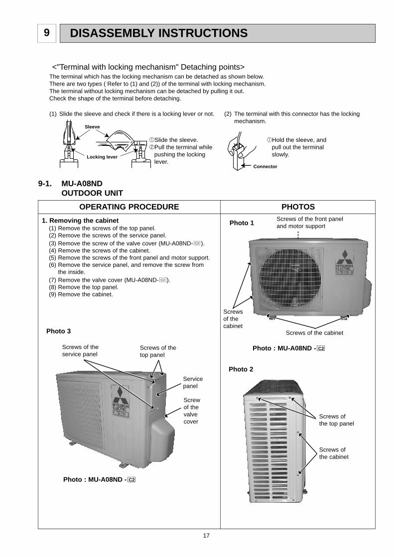
DISASSEMBLY INSTRUCTIONS9
(1) Slide the sleeve and check if there is a locking lever or not. (2) The terminal with this connector has the locking mechanism.
1Slide the sleeve.2Pull the terminal while pushing the locking lever.
1Hold the sleeve, and pull out the terminal slowly.
The terminal which has the locking mechanism can be detached as shown below.There are two types ( Refer to (1) and (2)) of the terminal with locking mechanism.The terminal without locking mechanism can be detached by pulling it out.Check the shape of the terminal before detaching.
<"Terminal with locking mechanism" Detaching points>
Connector
Sleeve
Locking lever
9-1. MU-A08NDOUTDOOR UNIT
OPERATING PROCEDURE PHOTOS
1. Removing the cabinet(1) Remove the screws of the top panel.(2) Remove the screws of the service panel.(3) Remove the screw of the valve cover (MU-A08ND- ).(4) Remove the screws of the cabinet.(5) Remove the screws of the front panel and motor support.(6) Remove the service panel, and remove the screw from
the inside.(7) Remove the valve cover (MU-A08ND- ).(8) Remove the top panel.(9) Remove the cabinet.
C2
C2
Photo 1
Photo 3
Screws of thetop panel
Servicepanel
Screws of theservice panel
Screws ofthe top panel
Screws ofthe cabinet
Screws of the cabinet
Photo 2
Screws of the front panel and motor support
Screws of thecabinet
Photo : MU-A08ND - C2
Photo : MU-A08ND - C2
Screwof thevalvecover
OB403B--1.qxp 07.6.26 10:28 AM Page 17

18
Compressorcapacitor (C1)
OPERATING PROCEDURE PHOTOS
2. Removing the electrical parts(1) Remove the service panel and the cabinet.(Refer to 1.)(2) Remove the following parts.
•Compressor capacitor (C1)•Outdoor fan capacitor (C2)•Terminal block (TB)
Photo 6
Compressor
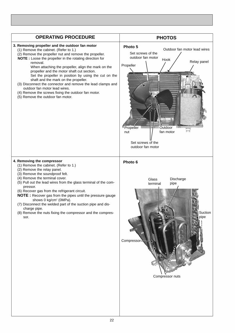
Terminal cover
3. Removing the propeller and the outdoor fan motor(1) Remove the cabinet. (Refer to 1.)(2) Remove the propeller nut.(3) Remove the propeller .NOTE : Loose the propeller in the rotating direction for
removal.When attaching the propeller, align the mark on thepropeller and the motor shaft cut section.Set the propeller in position by using the cut on theshaft and the mark on the propeller.
(4) Remove the lead clamps and the outdoor fan motor lead wires.
(5) Remove the screws fixing the outdoor fan motor.(6) Remove the outdoor fan motor.
Photo 5
Suction pipeDischarge pipe
Compressor nuts
4. Removing the compressor(1) Remove the cabinet. (Refer to 1.)(2) Remove the relay panel.(3) Remove the soundproof felt.(4) Remove the terminal cover on the compressor.(5) Disconnect lead wires from the glass terminal of the com-
pressor.(6) Recover gas from the refrigerant circuit.NOTE : Recover gas from the pipes until the pressure gauge
shows 0 kg/cm2 (0MPa).(7) Disconnect the welded part of the discharge pipe(8) Disconnect the welded part of the suction pipe.(9) Remove the nuts fixing the compressor.(10) Remove the compressor.
Glass terminal
Photo 4 Outdoor fancapacitor (C2)
Terminal block
Lead clamp
Propeller Propeller nut
Outdoorfan motor
Set screws ofoutdoor fan motor
OB403B--1.qxp 07.6.26 10:28 AM Page 18
19
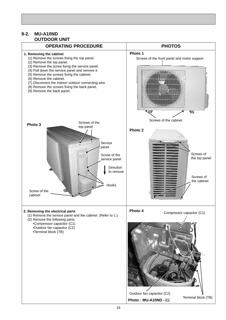
9-2. MU-A10NDOUTDOOR UNIT
OPERATING PROCEDURE PHOTOS
1. Removing the cabinet(1) Remove the screws fixing the top panel.(2) Remove the top panel.(3) Remove the screw fixing the service panel.(4) Pull down the service panel and remove it.(5) Remove the screws fixing the cabinet.(6) Remove the cabinet.(7) Disconnect the indoor/ outdoor connecting wire.(8) Remove the screws fixing the back panel.(9) Remove the back panel.
Photo 1
Photo 3
Screws ofthe top panel
Screws ofthe cabinet
Screws of the cabinet
Photo 2
Screws of the front panel and motor support
Screws of thetop panel
Servicepanel
Screw of thecabinet
Direction to remove
Hooks
Screw of theservice panel
2. Removing the electrical parts(1) Remove the service panel and the cabinet. (Refer to 1.)(2) Remove the following parts.
•Compressor capacitor (C1)•Outdoor fan capacitor (C2)•Terminal block (TB)
Photo 4
Outdoor fan capacitor (C2)
Compressor capacitor (C1)
Terminal block (TB)Photo : MU-A10ND - C1
OB403B--1.qxp 07.6.26 11:30 AM Page 19
20
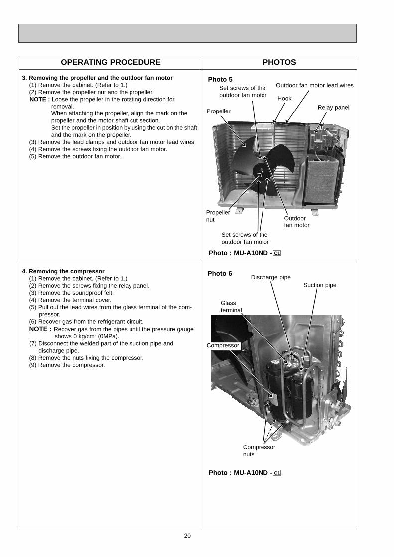
Glass terminal
OPERATING PROCEDURE PHOTOS
3. Removing the propeller and the outdoor fan motor(1) Remove the cabinet. (Refer to 1.)(2) Remove the propeller nut and the propeller.NOTE : Loose the propeller in the rotating direction for
removal.When attaching the propeller, align the mark on the propeller and the motor shaft cut section.Set the propeller in position by using the cut on the shaftand the mark on the propeller.
(3) Remove the lead clamps and outdoor fan motor lead wires.(4) Remove the screws fixing the outdoor fan motor.(5) Remove the outdoor fan motor.
Photo 5
Propeller
Propeller nut Outdoor
fan motor
Set screws of theoutdoor fan motor Hook
Relay panel
Outdoor fan motor lead wires
Set screws of theoutdoor fan motor
4. Removing the compressor(1) Remove the cabinet. (Refer to 1.)(2) Remove the screws fixing the relay panel.(3) Remove the soundproof felt.(4) Remove the terminal cover.(5) Pull out the lead wires from the glass terminal of the com-
pressor.(6) Recover gas from the refrigerant circuit.NOTE : Recover gas from the pipes until the pressure gauge
shows 0 kg/cm2 (0MPa).(7) Disconnect the welded part of the suction pipe and
discharge pipe.(8) Remove the nuts fixing the compressor.(9) Remove the compressor.
Photo 6
Compressor
Suction pipeDischarge pipe
Compressor nuts
Photo : MU-A10ND - C1
Photo : MU-A10ND - C1
OB403B--1.qxp 07.6.26 10:28 AM Page 20
21
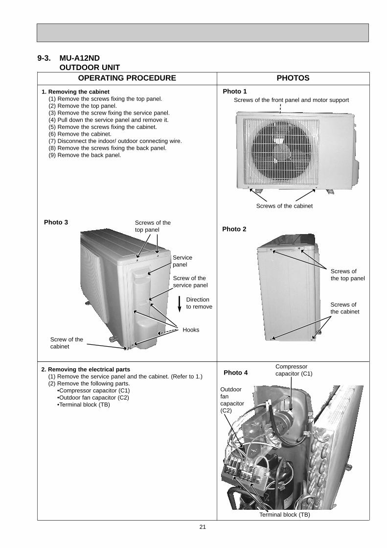
OPERATING PROCEDURE PHOTOS
2. Removing the electrical parts(1) Remove the service panel and the cabinet. (Refer to 1.)(2) Remove the following parts.
•Compressor capacitor (C1)•Outdoor fan capacitor (C2)•Terminal block (TB)
9-3. MU-A12ND OUTDOOR UNIT
Photo 4
1. Removing the cabinet(1) Remove the screws fixing the top panel.(2) Remove the top panel.(3) Remove the screw fixing the service panel.(4) Pull down the service panel and remove it.(5) Remove the screws fixing the cabinet.(6) Remove the cabinet.(7) Disconnect the indoor/ outdoor connecting wire.(8) Remove the screws fixing the back panel.(9) Remove the back panel.
Photo 1
Screws of the cabinet
Screws of the front panel and motor support
Photo 3 Screws of thetop panel
Servicepanel
Screw of thecabinet
Direction to remove
Hooks
Screw of theservice panel
Screws ofthe top panel
Screws ofthe cabinet
Photo 2
Outdoorfan capacitor(C2)
Compressorcapacitor (C1)
Terminal block (TB)
OB403B--1.qxp 07.6.26 11:39 AM Page 21
22
PHOTOS
Photo 6
Photo 5
OPERATING PROCEDURE
3. Removing propeller and the outdoor fan motor(1) Remove the cabinet. (Refer to 1.)(2) Remove the propeller nut and remove the propeller.NOTE : Loose the propeller in the rotating direction for
removal.When attaching the propeller, align the mark on the propeller and the motor shaft cut section.Set the propeller in position by using the cut on theshaft and the mark on the propeller.
(3) Disconnect the connector and remove the lead clamps andoutdoor fan motor lead wires.
(4) Remove the screws fixing the outdoor fan motor.(5) Remove the outdoor fan motor.
4. Removing the compressor(1) Remove the cabinet. (Refer to 1.)(2) Remove the relay panel.(3) Remove the soundproof felt.(4) Remove the terminal cover.(5) Pull out the lead wires from the glass terminal of the com-
pressor.(6) Recover gas from the refrigerant circuit.NOTE : Recover gas from the pipes until the pressure gauge
shows 0 kg/cm2 (0MPa).(7) Disconnect the welded part of the suction pipe and dis-
charge pipe.(8) Remove the nuts fixing the compressor and the compres-
sor.
Glassterminal
Dischargepipe
Suctionpipe
Compressor nuts
Compressor
Propeller
Propeller nut
Outdoorfan motor
Set screws of theoutdoor fan motor
Hook Relay panel
Outdoor fan motor lead wires
Set screws of theoutdoor fan motor
OB403B--1.qxp 07.6.26 10:29 AM Page 22
23
OPERATING PROCEDURE PHOTOS
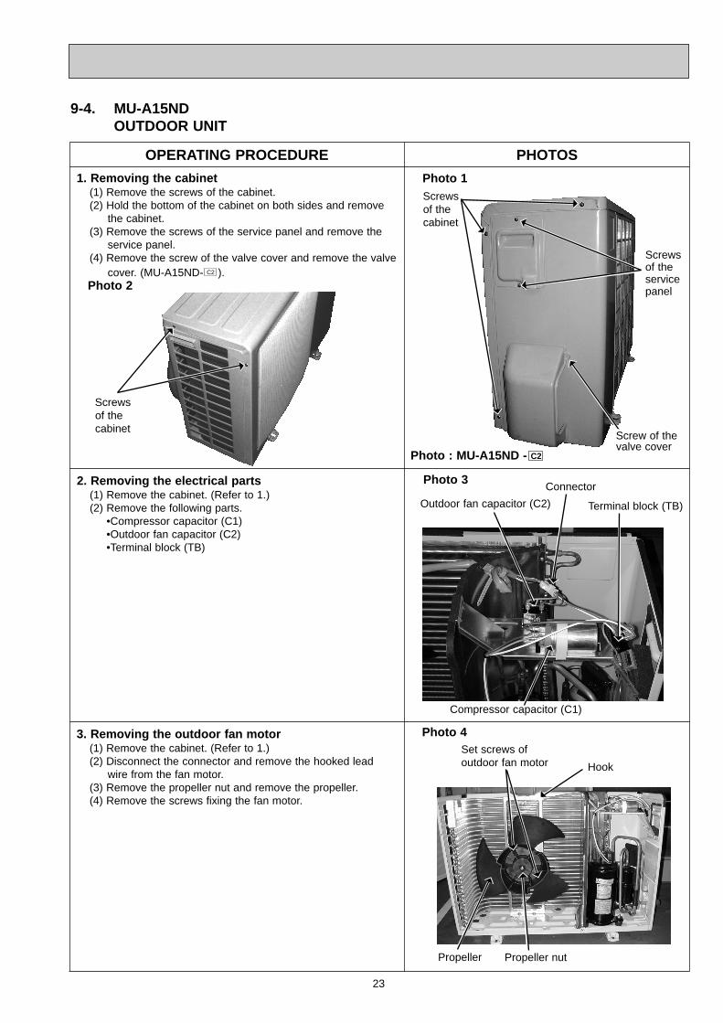
1. Removing the cabinet(1) Remove the screws of the cabinet.(2) Hold the bottom of the cabinet on both sides and remove
the cabinet.(3) Remove the screws of the service panel and remove the
service panel.(4) Remove the screw of the valve cover and remove the valve
cover. (MU-A15ND- ).C2
2. Removing the electrical parts(1) Remove the cabinet. (Refer to 1.)(2) Remove the following parts.
•Compressor capacitor (C1)•Outdoor fan capacitor (C2)•Terminal block (TB)
Photo 1
Photo 3
Photo 2
Screwsof thecabinet
Screwsof thecabinet
Screws of the servicepanel
Compressor capacitor (C1)
9-4. MU-A15NDOUTDOOR UNIT
Outdoor fan capacitor (C2) Terminal block (TB)
Connector
3. Removing the outdoor fan motor(1) Remove the cabinet. (Refer to 1.)(2) Disconnect the connector and remove the hooked lead
wire from the fan motor.(3) Remove the propeller nut and remove the propeller.(4) Remove the screws fixing the fan motor.
Photo 4
Hook
Propeller Propeller nut
Set screws ofoutdoor fan motor
Screw of thevalve cover
Photo : MU-A15ND - C2
OB403B--1.qxp 07.6.26 10:29 AM Page 23
24
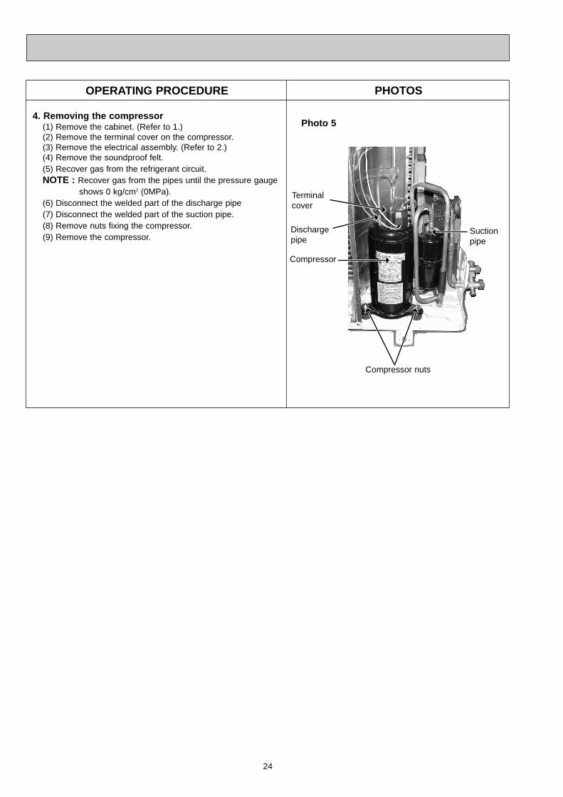
PHOTOS
4. Removing the compressor(1) Remove the cabinet. (Refer to 1.)(2) Remove the terminal cover on the compressor.(3) Remove the electrical assembly. (Refer to 2.)(4) Remove the soundproof felt.(5) Recover gas from the refrigerant circuit.NOTE : Recover gas from the pipes until the pressure gauge
shows 0 kg/cm2 (0MPa).(6) Disconnect the welded part of the discharge pipe(7) Disconnect the welded part of the suction pipe.(8) Remove nuts fixing the compressor.(9) Remove the compressor.
Photo 5
Compressor
Dischargepipe
Suctionpipe
Compressor nuts
OPERATING PROCEDURE
Terminalcover
OB403B--1.qxp 07.6.26 10:29 AM Page 24
25
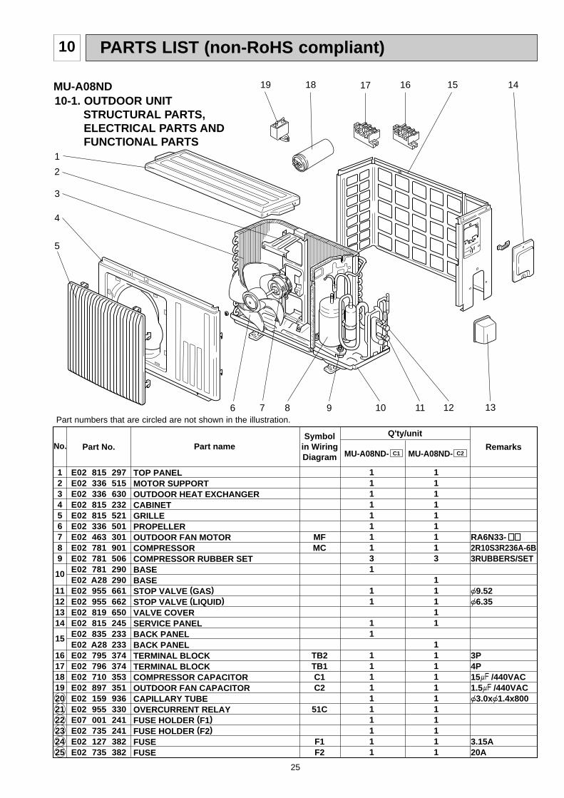
PARTS LIST (non-RoHS compliant)10
Part numbers that are circled are not shown in the illustration.
10-1. OUTDOOR UNIT STRUCTURAL PARTS,ELECTRICAL PARTS AND FUNCTIONAL PARTS
MU-A08ND
No. Part No. Part name RemarksSymbol
in WiringDiagram
Q'ty/unit
123456789
10
11121314
15
16171819202122232425
RA6N33-2R10S3R236A-6B3RUBBERS/SET
{9.52{6.35
3P4P15+ /440VAC1.5+ /440VAC{3.0x{1.4x800
3.15A20A
MFMC
TB2TB1C1C2
51C
F1F2
MU-A08ND- MU-A08ND-
1111111131
11
11
1111111111
111111113
11111
11111111111
TOP PANELMOTOR SUPPORTOUTDOOR HEAT EXCHANGERCABINETGRILLEPROPELLEROUTDOOR FAN MOTORCOMPRESSORCOMPRESSOR RUBBER SETBASEBASESTOP VALVE (GAS)STOP VALVE (LIQUID)VALVE COVERSERVICE PANELBACK PANELBACK PANEL TERMINAL BLOCKTERMINAL BLOCKCOMPRESSOR CAPACITOROUTDOOR FAN CAPACITORCAPILLARY TUBEOVERCURRENT RELAYFUSE HOLDER (F1)FUSE HOLDER (F2)FUSEFUSE
C1 C2
E02 815 297E02 336 515E02 336 630E02 815 232E02 815 521E02 336 501E02 463 301E02 781 901E02 781 506E02 781 290E02 A28 290E02 955 661E02 955 662E02 819 650E02 815 245E02 835 233E02 A28 233E02 795 374E02 796 374E02 710 353E02 897 351E02 159 936E02 955 330E07 001 241E02 735 241E02 127 382E02 735 382
1
5
8 10 119
4
12
2
3
1415
6 7
18 1619 17
13
OB403B--1.qxp 07.6.26 10:29 AM Page 25
26
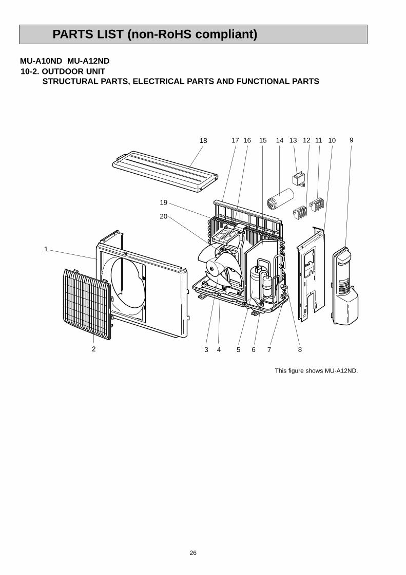
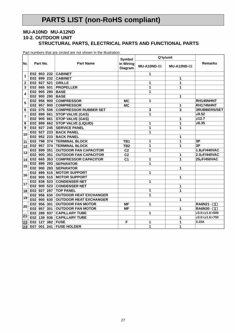
10-2. OUTDOOR UNITSTRUCTURAL PARTS, ELECTRICAL PARTS AND FUNCTIONAL PARTS
MU-A10ND MU-A12ND
1
2
1518 10 9
3 4 5 6 7 8
1617
19
20
111314
This figure shows MU-A12ND.
12
PARTS LIST (non-RoHS compliant)
OB403B--1.qxp 07.6.26 10:29 AM Page 26
27
E02 903 232E02 899 232E02 927 521E02 665 501E02 905 290E02 900 290E02 956 900E02 957 900E02 075 506E02 899 661E02 900 661E02 899 662E02 927 245E02 927 233E02 952 233E02 798 374E02 957 374E02 899 351E02 900 351E02 665 353E02 899 293E02 900 293E02 899 515E02 900 515E02 838 523E02 900 523E02 927 297E02 956 630E02 900 630E02 956 301E02 957 301E02 289 937E02 139 936E02 127 382E07 001 241
1
23
4
5
6
7
89
10
1112
13
14
15
16
17
18
19
20
21
2223
RH145NHNTRH174NHNT3RUBBERS/SET{9.52{12.7{6.35
3P3P1.8µF/440VAC2.0µF/440VAC25µF/450VAC
RA6N21 -RA6N30 -{3.0✕ {1.6✕ 500{3.0✕ {1.6✕ 7503.15A
MCMC
TB1TB2C2C2C1
MFMF
F
1
111
1
31
111
111
11
1
1
11
1
1
11
111
1
13
111
111
11
1
1
11
1
1
111
Symbolin WiringDiagram
Q'ty/unit
RemarksPart No.No. Part Name
CABINETCABINETGRILLEPROPELLERBASEBASECOMPRESSORCOMPRESSORCOMPRESSOR RUBBER SETSTOP VALVE (GAS)STOP VALVE (GAS)STOP VALVE (LIQUID)SERVICE PANELBACK PANELBACK PANELTERMINAL BLOCKTERMINAL BLOCKOUTDOOR FAN CAPACITOROUTDOOR FAN CAPACITORCOMPRESSOR CAPACITORSEPARATORSEPARATORMOTOR SUPPORTMOTOR SUPPORTCONDENSER NETCONDENSER NETTOP PANELOUTDOOR HEAT EXCHANGEROUTDOOR HEAT EXCHANGEROUTDOOR FAN MOTOROUTDOOR FAN MOTORCAPILLARY TUBECAPILLARY TUBEFUSEFUSE HOLDER
MU-A10ND- C1 MU-A12ND- C1
MU-A10ND MU-A12ND10-2. OUTDOOR UNIT
STRUCTURAL PARTS, ELECTRICAL PARTS AND FUNCTIONAL PARTS
Part numbers that are circled are not shown in the illustration.
PARTS LIST (non-RoHS compliant)
OB403B--1.qxp 07.6.26 10:29 AM Page 27
28
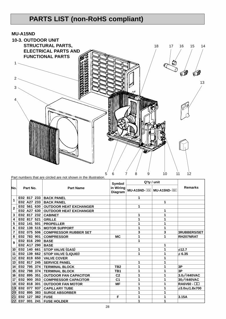
MU-A15ND10-3. OUTDOOR UNIT
STRUCTURAL PARTS,ELECTRICAL PARTS AND FUNCTIONAL PARTS
1
4
16
2
17 15 14
13
6 7 98
18
5 10 11
No. Part No. Part Name RemarksSymbol
in WiringDiagram
Q'ty / unit
MU-A15ND- C1 MU-A15ND- C2
3RUBBERS/SETRH207NRAT
{12.7{ 6.35
3P3P3.0+/440VAC30+/440VACRA6V60 -{3.0x{1.8x700
3.15A
1
2
345678
9
10111213141516171819202122
1
1
1111311
11
1111111111
1
1111131
11111111111111
E02 817 233E02 A27 233E02 561 630E02 A27 630E02 817 232E02 817 521E02 141 501E02 139 515E02 075 506E02 783 901E02 816 290E02 A17 290E02 140 661E02 139 662E02 819 650E02 817 245E02 795 374E02 798 374E02 895 351E02 900 353E02 818 301E02 077 937E02 895 383E02 127 382E07 001 241
BACK PANELBACK PANELOUTDOOR HEAT EXCHANGEROUTDOOR HEAT EXCHANGERCABINETGRILLEPROPELLERMOTOR SUPPORTCOMPRESSOR RUBBER SETCOMPRESSORBASEBASESTOP VALVE (GAS)STOP VALVE (LIQUID)VALVE COVERSERVICE PANELTERMINAL BLOCKTERMINAL BLOCKOUTDOOR FAN CAPACITORCOMPRESSOR CAPACITOROUTDOOR FAN MOTORCAPILLARY TUBESURGE ABSORBERFUSEFUSE HOLDER
MC
TB2TB1C2C1MF
F
3
12Part numbers that are circled are not shown in the illustration.
PARTS LIST (non-RoHS compliant)
OB403B--1.qxp 07.6.26 10:29 AM Page 28
29
RoHS PARTS LIST (RoHS compliant)11
Part numbers that are circled are not shown in the illustration.
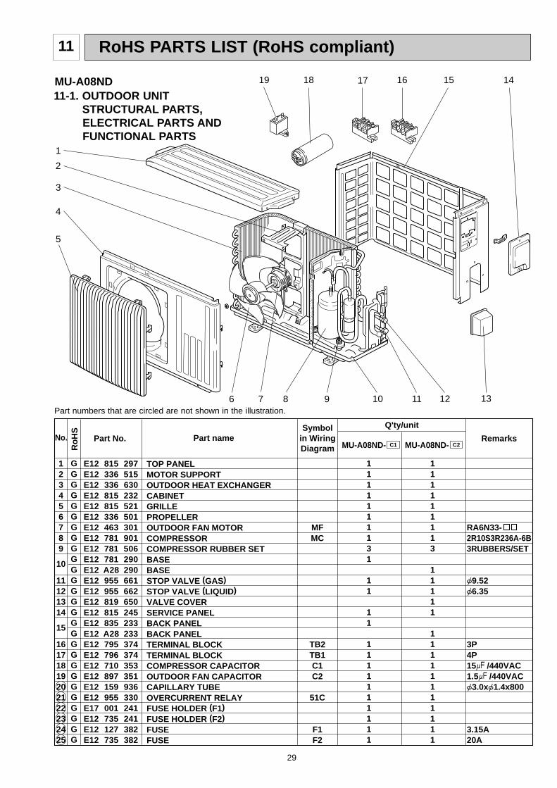
11-1. OUTDOOR UNIT STRUCTURAL PARTS,ELECTRICAL PARTS AND FUNCTIONAL PARTS
MU-A08ND
No. Part No. Part name RemarksSymbol
in WiringDiagram
Q'ty/unit
123456789
10
11121314
15
16171819202122232425
RA6N33-2R10S3R236A-6B3RUBBERS/SET
{9.52{6.35
3P4P15+ /440VAC1.5+ /440VAC{3.0x{1.4x800
3.15A20A
MFMC
TB2TB1C1C2
51C
F1F2
MU-A08ND- MU-A08ND-
1111111131
11
11
1111111111
111111113
11111
11111111111
TOP PANELMOTOR SUPPORTOUTDOOR HEAT EXCHANGERCABINETGRILLEPROPELLEROUTDOOR FAN MOTORCOMPRESSORCOMPRESSOR RUBBER SETBASEBASESTOP VALVE (GAS)STOP VALVE (LIQUID)VALVE COVERSERVICE PANELBACK PANELBACK PANEL TERMINAL BLOCKTERMINAL BLOCKCOMPRESSOR CAPACITOROUTDOOR FAN CAPACITORCAPILLARY TUBEOVERCURRENT RELAYFUSE HOLDER (F1)FUSE HOLDER (F2)FUSEFUSE
C1 C2
E12 815 297E12 336 515E12 336 630E12 815 232E12 815 521E12 336 501E12 463 301E12 781 901E12 781 506E12 781 290E12 A28 290E12 955 661E12 955 662E12 819 650E12 815 245E12 835 233E12 A28 233E12 795 374E12 796 374E12 710 353E12 897 351E12 159 936E12 955 330E17 001 241E12 735 241E12 127 382E12 735 382
GGGGGGGGGGGGGGGGGGGGGGGGGGG
Ro
HS
1
5
8 10 119
4
12
2
3
1415
6 7
18 1619 17
13
OB403B--1.qxp 07.6.26 10:29 AM Page 29
30
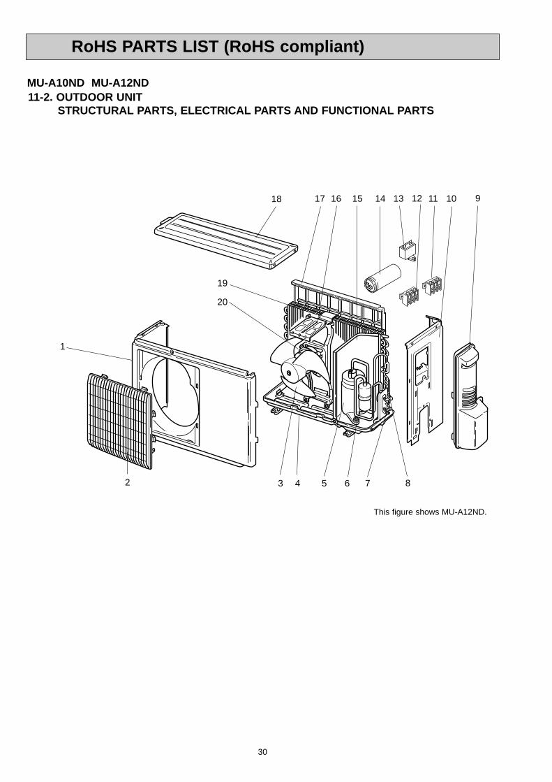
11-2. OUTDOOR UNITSTRUCTURAL PARTS, ELECTRICAL PARTS AND FUNCTIONAL PARTS
MU-A10ND MU-A12ND
1
2
1518 10 9
3 4 5 6 7 8
1617
19
20
111314
This figure shows MU-A12ND.
12
RoHS PARTS LIST (RoHS compliant)
OB403B--1.qxp 07.6.26 10:29 AM Page 30
31
Part No.
E12 903 232E12 899 232E12 927 521E12 665 501E12 905 290E12 900 290E12 956 900E12 957 900E12 075 506E12 899 661E12 900 661E12 899 662E12 A45 662E12 927 245E12 927 233E12 952 233E12 798 374E12 957 374E12 899 351E12 900 351E12 665 353E12 899 293E12 900 293E12 899 515E12 900 515E12 838 523E12 929 523E12 900 523E12 927 297E12 956 630E12 D02 630E12 900 630E12 956 301E12 957 301E12 289 937E12 746 936E12 139 936E12 127 382E17 001 241
1
23
4
5
6
7
8
9
10
1112
13
14
15
16
17
18
19
20
21
2223
RH145NHNTRH174NHNT3RUBBERS/SET{9.52{12.7{6.35{6.35
3P3P1.8µF/440VAC2.0µF/440VAC25µF/450VAC
RA6N21 -RA6N30 -{3.0✕ {1.6✕ 500{3.0✕ {1.6✕ 850{3.0✕ {1.6✕ 7503.15A
MCMC
TB1TB2C2C2C1
MFMF
F
1
111
1
31
1
11
111
11
1
1
11
1
1
11
111
1
13
11
1
111
11
1
1
11
1
1
111
Symbolin WiringDiagram
Q'ty/unit
RemarksNo. Part Name
CABINETCABINETGRILLEPROPELLERBASEBASECOMPRESSORCOMPRESSORCOMPRESSOR RUBBER SETSTOP VALVE (GAS)STOP VALVE (GAS)STOP VALVE (LIQUID)STOP VALVE (LIQUID)SERVICE PANELBACK PANELBACK PANELTERMINAL BLOCKTERMINAL BLOCKOUTDOOR FAN CAPACITOROUTDOOR FAN CAPACITORCOMPRESSOR CAPACITORSEPARATORSEPARATORMOTOR SUPPORTMOTOR SUPPORTCONDENSER NETCONDENSER NETCONDENSER NETTOP PANELOUTDOOR HEAT EXCHANGEROUTDOOR HEAT EXCHANGEROUTDOOR HEAT EXCHANGEROUTDOOR FAN MOTOROUTDOOR FAN MOTORCAPILLARY TUBECAPILLARY TUBECAPILLARY TUBEFUSEFUSE HOLDER
MU-A10ND- C1
MU-A12ND- C1
MU-A10ND- C2
1
111
1
31
111
111
1
1
1
1
1
1
1
1
11
GGGGGGGGGGGGGGGGGGGGGGGGGGGGGGGGGGGGGGG
Ro
HS
MU-A10ND MU-A12ND11-2. OUTDOOR UNIT
STRUCTURAL PARTS, ELECTRICAL PARTS AND FUNCTIONAL PARTS
Part numbers that are circled are not shown in the illustration.
RoHS PARTS LIST (RoHS compliant)
OB403B--2.qxp 07.6.26 10:30 AM Page 31
32
MU-A15ND11-3. OUTDOOR UNIT
STRUCTURAL PARTS,ELECTRICAL PARTS AND FUNCTIONAL PARTS
1
4
16
2
17 15 14
13
6 7 98
18
5 10 11
No. Part No. Part Name RemarksSymbol
in WiringDiagram
Q'ty / unit
MU-A15ND- C1 MU-A15ND- C2
3RUBBERS/SETRH207NRAT
{12.7{ 6.35
3P3P3.0+/440VAC30+/440VACRA6V60 -{3.0x{1.8x700
3.15A
1
2
345678
9
10111213141516171819202122
1
1
1111311
11
1111111111
1
1111131
11111111111111
E12 817 233E12 A27 233E12 561 630E12 A27 630E12 817 232E12 817 521E12 141 501E12 139 515E12 075 506E12 783 901E12 816 290E12 A17 290E12 140 661E12 139 662E12 819 650E12 817 245E12 795 374E12 798 374E12 895 351E12 900 353E12 818 301E12 077 937E12 895 383E12 127 382E17 001 241
BACK PANELBACK PANELOUTDOOR HEAT EXCHANGEROUTDOOR HEAT EXCHANGERCABINETGRILLEPROPELLERMOTOR SUPPORTCOMPRESSOR RUBBER SETCOMPRESSORBASEBASESTOP VALVE (GAS)STOP VALVE (LIQUID)VALVE COVERSERVICE PANELTERMINAL BLOCKTERMINAL BLOCKOUTDOOR FAN CAPACITORCOMPRESSOR CAPACITOROUTDOOR FAN MOTORCAPILLARY TUBESURGE ABSORBERFUSEFUSE HOLDER
MC
TB2TB1C2C1MF
F
GGGGGGGGGGGGGGGGGGGGGGGGG
Ro
HS
3
12Part numbers that are circled are not shown in the illustration.
RoHS PARTS LIST (RoHS compliant)
OB403B--2.qxp 07.6.26 10:30 AM Page 32
33
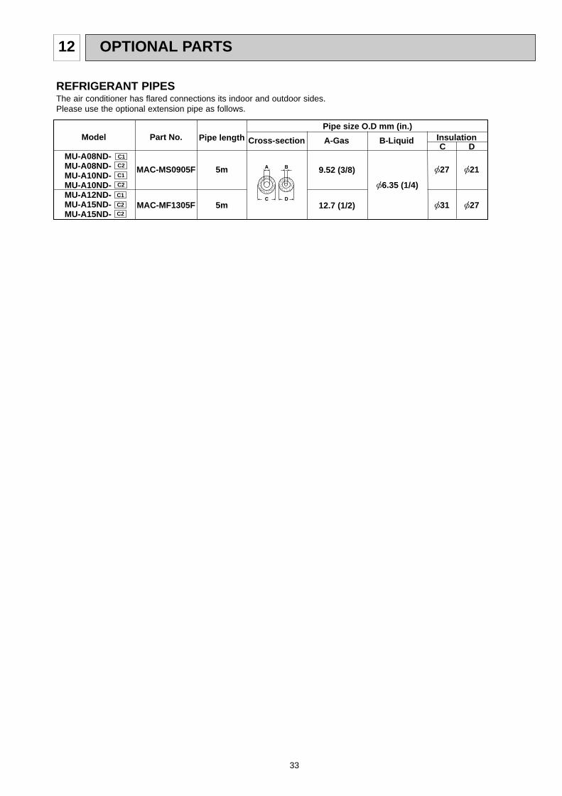
OPTIONAL PARTS12
C1
C1
C2
C1
C2
C2
C2
MAC-MS0905F
MAC-MF1305F
5m
5m
[6.35 (1/4)
[27
[31
[21
[27
9.52 (3/8)
12.7 (1/2)
MU-A08ND-MU-A08ND-MU-A10ND-MU-A10ND-MU-A12ND-MU-A15ND-MU-A15ND-
Pipe length Cross-sectionPart No.Model A-Gas B-Liquid
Pipe size O.D mm (in.)Insulation
DC
��������
REFRIGERANT PIPESThe air conditioner has flared connections its indoor and outdoor sides.Please use the optional extension pipe as follows.
OB403B--2.qxp 07.6.26 10:30 AM Page 33

34
OB403B--2.qxp 07.6.26 10:30 AM Page 34

35
OB403B--2.qxp 07.6.26 10:30 AM Page 35

HEAD OFFICE: TOKYO BLDG., 2-7-3, MARUNOUCHI, CHIYODA-KU, TOKYO 100-8310, JAPAN
CC Copyright 2005 MITSUBISHI ELECTRIC ENGINEERING CO.,LTD.Distributed in Jul. 2007. No.OB403 REVISED EDITION-B 7Distributed in Oct. 2005. No.OB403 REVISED EDITION-A 6Reprinted in Apr. 2005. No.OB403 100Distributed in Apr. 2005. No.OB403 6Made in Japan
New publication, effective Jul. 2007Specifications subject to change without notice.
TM
OB403B--2.qxp 07.6.26 0:07 PM Page 36
![Untitled-1 [nonul.mylinkdrive.com]PCH,PKH-18... · Title: Untitled-1 Author: DOC Created Date: 7/17/1998 4:26:44 PM](https://img.pdfslide.us/doc/110x75/5ec3f36b16c1f944811b126b/untitled-1-nonul-pchpkh-18-title-untitled-1-author-doc-created-date.jpg)