Embed Size (px)
Citation preview

IM 767361-01E2nd Edition
Digital Manometer
1IM 767361-01E
ForewordThank you for purchasing the YOKOGAWA MT200 Series* Digital Manometer.
This user’s manual contains useful information about the instrument’s functions
and operating procedures MT210, MT210F, and MT220, as well as precautions
that should be observed during use. To ensure proper use of the instrument,
please read this manual thoroughly before beginning operation.
After reading the manual, keep it in a convenient location for quick reference
whenever a question arises during operation of the instrument.
*MT200 series: MT210 (pressure measurement only)
MT210F (pressure measurement only, includes a
measurement mode switching function)
MT220 (includes DMM and 24 VDC output functions)
Notes• The contents of this manual are subject to change without prior notice as a
result of improvements in the instrument’s performance and functions.
• Every effort has been made in the preparation of this manual to ensure the
accuracy of its contents. However, should you have any questions or find any
errors, please contact your nearest YOKOGAWA representative as listed on
the back cover of this manual.
• Copying or reproducing any or all parts of the contents of this manual without
the permission of Yokogawa Electric Corporation is strictly prohibited.
Trademarks• The PC-9800 Series is a product line of NEC Corporation.
• Adobe and Adobe Acrobat are trademarks of Adobe Systems
Incorporated.
• VCO is a registered trademark of SWAGELOK in the United States.
RevisionsJanuary 2001 1st Edition
March 2001 2nd Edition
Disk No. BA41
2nd Edition : March 2001 (YK)
All Rights Reserved, Copyright © 2001 Yokogawa Electric Corporation
2 IM 767361-01E
Safety Precautions
The following general safety precautions must be observed during all phases of
operation, service, and repair of this instrument. If this instrument is used in
a manner not specified in this manual, the protection provided by this
instrument may be impaired. Also, Yokogawa Electric Corporation assumes
no liability for the customer’s failure to comply with these requirements.
General definitions of safety symbols used on the instrument and in the
manuals
Handle with Care (To avoid injury, death of personnel, or damage
to the instrument, the user must refer to an explanation in the
user’s manual or service manual.)
Alternating current
Direct current
ON (power) In-position of a bistable push control
OFF (power) Out-position of a bistable push control
WARNING
• Power SupplyBefore turning on the power, ensure that the source voltage matches
the voltage of the power supply.• Power Cord and Plug
To prevent an electric shock or fire, be sure to use the power supply
cord supplied by YOKOGAWA. The main power plug can only beplugged into an outlet with a protective grounding terminal. Use of anextension cord with no protective grounding wire will render the
protection feature ineffective.• Protective Grounding
To prevent electric shock, be sure to connect the protective grounding
before turning on the power. The power cord included with thisinstrument is a 3-prong cord with a grounding wire. Connect the powercord to a 3-prong AC outlet with a protective grounding terminal. Also,
when using a 3-prong to 2-prong adapter, be sure to connect theground wire on the adapter to the protective ground wire terminal.
• Necessity of Protective GroundingNever cut off the internal or external protective grounding wire ordisconnect the wiring from the protective grounding terminal.
• Faulty Protection FeatureNever operate the instrument if the protective grounding or fuseappears faulty. Before commencing operation, always make sure thatthe protection feature has no defects.
• External ConnectionSecurely connect the protective grounding before connecting to theitem under measurement or control unit.

3IM 767361-01E
• FuseTo prevent fire, be sure to use a fuse with the specified ratings (current,
voltage, and type). Before replacing the fuse, turn both the POWERswitch and the MAIN POWER switch OFF and unplug the power cord.Do not use any fuse other than the specified one. Also do not short-
circuit the fuse holder.• Precautions against Explosion
This instrument is not explosion-proof. Do not operate the instrument
in the presence of flammable liquids or vapors. Operation of theinstrument in such an environment constitutes a safety hazard.
• Do Not Remove CoversThe cover should be removed by qualified personnel only. There arehigh voltage components inside the instrument.
• Measuring High-Pressure Gases• Use a measuring tube and pressure connector rigid enough to
withstand the pressure being measured.• Check the measuring tube, and pressure connector and their joints to
ensure that there is no leaking of the fluid being measured orseparation in the joints. Any such leakage or separation can behazardous to personnel or equipment near the instrument. Exercise
due caution; the greater the pressure in the tubes, the greater thedanger.
• Do not measure flammable, explosive, toxic, or corrosive fluids.
• Limitation of PressureApplying a pressure exceeding the prescribed allowable input candamage the instrument. In addition, the applied pressure may be
passed on to the device that is connected to the output connector, andcause secondary accidents.
CAUTION
• Do not measure the pressure of a gas or liquid which might causecorrosion in pipes or components, or of a fluid whose temperature is50°C or higher, or of a fluid which is a mixture of gas and liquid.
Make sure that the gas to be measured is dry and free of oil.• For health and safety reasons, do not measure any liquid foodstuffs.• Although the instrument is designed with shock resistance taken into
account, handle the instrument with care to maintain high measurementaccuracy.
• Do not use the instrument in a place where the ambient temperature
fluctuates rapidly, otherwise measurement errors may result.• Do not overcharge the batteries.• Do not operate the instrument in a place where wind or air blows
noticeably, otherwise the measurement accuracy will decrease.• This is an overvoltage category CAT II (EN61010-1) instrument.
4 IM 767361-01E
Symbols Used in this ManualType Symbol MeaningNote Affixed to the main unit, this indicates that to avoid
injury, death, or damage to the instrument, theoperator must refer to the correspondingexplanation in the manual.
WARNING Describes precautions that should be observed toprevent injury or death to the user.
CAUTION Describes precautions that should be observed toprevent damage to the instrument.
Note Provides information that is important for properoperation of the instrument.
Key HOLD Indicates a key on the front panel.
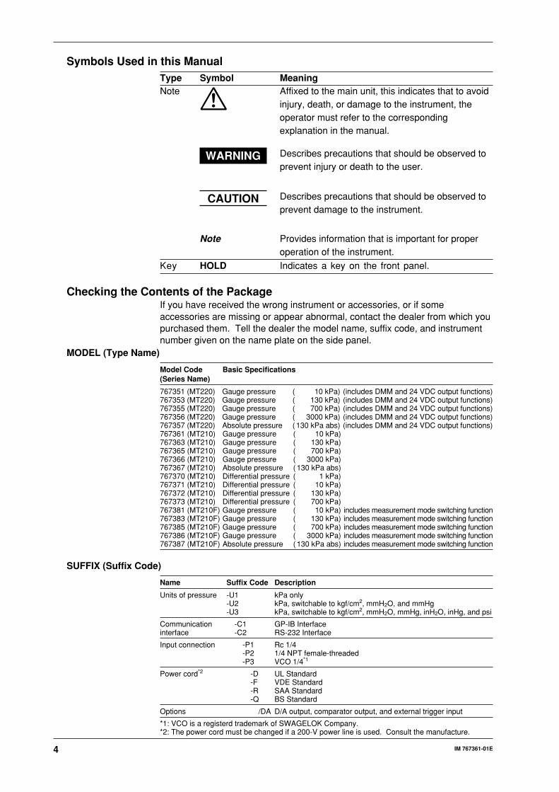
Checking the Contents of the PackageIf you have received the wrong instrument or accessories, or if someaccessories are missing or appear abnormal, contact the dealer from which youpurchased them. Tell the dealer the model name, suffix code, and instrumentnumber given on the name plate on the side panel.
MODEL (Type Name)
Model Code Basic Specifications(Series Name)
767351 (MT220) Gauge pressure ( 10 kPa) (includes DMM and 24 VDC output functions)767353 (MT220) Gauge pressure ( 130 kPa) (includes DMM and 24 VDC output functions)767355 (MT220) Gauge pressure ( 700 kPa) (includes DMM and 24 VDC output functions)767356 (MT220) Gauge pressure ( 3000 kPa) (includes DMM and 24 VDC output functions)767357 (MT220) Absolute pressure ( 130 kPa abs) (includes DMM and 24 VDC output functions)767361 (MT210) Gauge pressure ( 10 kPa)767363 (MT210) Gauge pressure ( 130 kPa)767365 (MT210) Gauge pressure ( 700 kPa)767366 (MT210) Gauge pressure ( 3000 kPa)767367 (MT210) Absolute pressure ( 130 kPa abs)767370 (MT210) Differential pressure ( 1 kPa)767371 (MT210) Differential pressure ( 10 kPa)767372 (MT210) Differential pressure ( 130 kPa)767373 (MT210) Differential pressure ( 700 kPa)767381 (MT210F) Gauge pressure ( 10 kPa) includes measurement mode switching function767383 (MT210F) Gauge pressure ( 130 kPa) includes measurement mode switching function767385 (MT210F) Gauge pressure ( 700 kPa) includes measurement mode switching function767386 (MT210F) Gauge pressure ( 3000 kPa) includes measurement mode switching function767387 (MT210F) Absolute pressure ( 130 kPa abs) includes measurement mode switching function
SUFFIX (Suffix Code)
Name Suffix Code Description
Units of pressure -U1 kPa only-U2 kPa, switchable to kgf/cm2, mmH2O, and mmHg-U3 kPa, switchable to kgf/cm2, mmH2O, mmHg, inH2O, inHg, and psi
Communication -C1 GP-IB Interfaceinterface -C2 RS-232 Interface
Input connection -P1 Rc 1/4-P2 1/4 NPT female-threaded-P3 VCO 1/4*1
Power cord*2 -D UL Standard-F VDE Standard-R SAA Standard-Q BS Standard
Options /DA D/A output, comparator output, and external trigger input
*1: VCO is a registerd trademark of SWAGELOK Company.*2: The power cord must be changed if a 200-V power line is used. Consult the manufacture.

5IM 767361-01E
Standard Accessories
The following standard accessories are supplied with the instrument. Make
sure that all items are present and undamaged.
User’s Manual(this manual) (1)
Remote connector for theoutput terminal (When the /DA option is installed)A1003JD
VCO body1 piece (for -P3), 2 pieces(for the 76737 -P3)B9320GU
Power fuse (2 pieces)(a spare, attached to the fuse holder)A1436EF
Current fuse (2 pieces)(a spare, attached to the fuse holder)A1431EF (MT220 only)
Rubber feet (2 pieces)A9088ZM
UL/CSA standardA1006WD
VDE standardA1009WD
BS standardA1054WD
SAA standardA1024WD
D F RQ
Power cord (one of the following power cordsis supplied according to the instrument’s suffix codes)
Measurement lead (MT220 only)B9280TZ
Connector for external DC powerA1036JC
Seal for measuring objectB9320NB
Optional Accessories
The following optional accessories are also available. Upon receipt of any
optional accessories, make sure that no items are missing or damaged.
Part Name Model/Part No. Minimum Purchase Quantity
Battery packSeal, screws (M5 × 40 mm × 4) 269913 1Ni-Cd batteries 269914 1 (3 Ni-Cd batteries as a set)Carrying case B9320ND 1Connector assembly for RC (for φ4 × φ6 vinyl tube) B9310RR 1Simple connector assembly (for φ4 × φ6 vinyl tube) B9310ZH 1Conversion connector (JIS, R1/4-Rc1/8) G9612BG 1Conversion connector (ANSI, R1/4-1/4NPT female) G9612BJ 1Conversion connector G9612BW 1(ANSI, R1/4-1/8NPT female)
Connector assembly for Rc B9310RR
Simple connector assebly B9310ZH
Conversion connector (JIS) G9612BG
Conversion connector (ANSI) G9612BJ
Conversion connector (ANSI) G9612BW
If you have any questions regarding optional accessories, or if you wish to place
an order, contact the dealer from whom you purchased the instrument.
6 IM 767361-01E
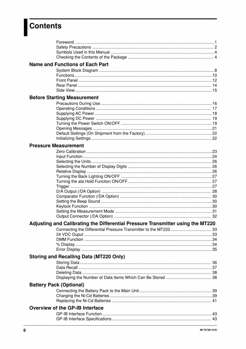
Contents
Foreword .........................................................................................................................1Safety Precautions ......................................................................................................... 2Symbols Used in this Manual ..........................................................................................4Checking the Contents of the Package .......................................................................... 4
Name and Functions of Each PartSystem Block Diagram ....................................................................................................8Functions .......................................................................................................................10Front Panel ....................................................................................................................12Rear Panel .................................................................................................................... 14Side View .......................................................................................................................15
Before Starting MeasurementPrecautions During Use.................................................................................................16Operating Conditions .................................................................................................... 17Supplying AC Power ......................................................................................................18Supplying DC Power .................................................................................................... 19Turning the Power Switch ON/OFF ...............................................................................19Opening Messages ........................................................................................................21Default Settings (On Shipment from the Factory) ..........................................................22Initializing Settings .........................................................................................................22
Pressure MeasurementZero Calibration .............................................................................................................23Input Function ................................................................................................................24Selecting the Units .........................................................................................................26Selecting the Number of Display Digits ........................................................................ 26Relative Display .............................................................................................................26Turning the Back Lighting ON/OFF ...............................................................................27Turning the ata Hold Function ON/OFF ........................................................................ 27Trigger ...........................................................................................................................27D/A Output (/DA Option) ............................................................................................... 28Comparator Function (/DA Option) ............................................................................... 30Setting the Beep Sound.................................................................................................30Keylock Function ...........................................................................................................30Setting the Measurement Mode ....................................................................................31Output Connector (/DA Option) .................................................................................... 32
Adjusting and Calibrating the Differential Pressure Transmitter using the MT220Connecting the Differential Pressure Transmitter to the MT220................................... 3324 VDC Ouput ...............................................................................................................33DMM Function ...............................................................................................................34% Display .......................................................................................................................34Error Display ..................................................................................................................35
Storing and Recalling Data (MT220 Only)Storing Data .................................................................................................................. 36Data Recall ....................................................................................................................37Deleting Data ................................................................................................................ 38Displaying the Number of Data Items Which Can Be Stored ........................................38
Battery Pack (Optional)Connecting the Battery Pack to the Main Unit ...............................................................39Charging the Ni-Cd Batteries .........................................................................................39Replacing the Ni-Cd Batteries ...................................................................................... 41
Overview of the GP-IB InterfaceGP-IB Interface Function ...............................................................................................43GP-IB Interface Specifications ...................................................................................... 43

7IM 767361-01E
Turning GP-IB ON/OFF .................................................................................................43Interface Messages Supported by the Instrument ........................................................ 44Switching between Remote and Local Mode ............................................................... 44Setting the Mode and Address ......................................................................................44Setting the GP-IB Interface........................................................................................... 45
Overview of the RS-232 InterfaceRS-232 Interface Functions ...........................................................................................46RS-232 Interface Specifications ....................................................................................46Connecting the RS-232 Interface Cable ........................................................................46Connector and Signal Names........................................................................................47Signal Direction .............................................................................................................47Table of RS-232 Standard Signals and Their JIS and CCITT Abbreviations .................48Handshaking ..................................................................................................................48Description of Each Handshaking Method ....................................................................49Precautions Regarding Data Receiving Control ............................................................50Setting the Data Format ............................................................................................... 50RS-232 Communications Settings .................................................................................51Selecting Normal or Talk-Only Mode .............................................................................51Setting the Handshaking Mode, Data Format, and Baud Rate .....................................52RS-232 Specific Commands .........................................................................................52
Before ProgrammingBasic Programming Format ...........................................................................................53Precautions when Programming .................................................................................. 53How to Use the Appendix ............................................................................................. 53
Troubleshooting, Maintenance, and InspectionItems to be Checked in Case of an Abnormality ............................................................54Error Codes and Corrective Actions ............................................................................. 54Calibrating the Pressure Measurement Function ..........................................................56Calibrating the DMM Function (MT220 Only) ............................................................... 56Recommended Replacement Parts ...............................................................................58Replacing the Fuse ........................................................................................................58
SpecificationsPressure Measurement Section (767351/767361/767381/767353/767363/767383/767355/767365/767385) ...............................................................................................60Pressure Measurement Section (767356/767366/767386/767357/767367/767387) ... 61Pressure Measurement Section (767370/767371) ........................................................62Pressure Measurement Section (767372/767373) ........................................................62Pressure Measurement Section (Common to All Models) .............................................63DCV and DCA Measurement Section, MT220 Only ......................................................6324 V Supply Section, MT220 Only .................................................................................63Data memory function, MT220 Only ............................................................................. 63Communication Function (install either one) .................................................................64Option /DA ....................................................................................................................64Common Specifications .................................................................................................65External Dimensions ......................................................................................................66
AppendixCommand List ......................................................................................................... App-1Communications Command List .............................................................................. App-2Status Byte Format ................................................................................................ App-12Data Output Format ............................................................................................... App-13Header Section ...................................................................................................... App-13Output Format for Recalled Data(Response to the “ORD” Command, MT220 Only) ............................................... App-15Output Format of Setup Information (Response to the “OS” Command) .............. App-15Sample Program.................................................................................................... App-16
Index
8 IM 767361-01E
Name and Functions of Each Part
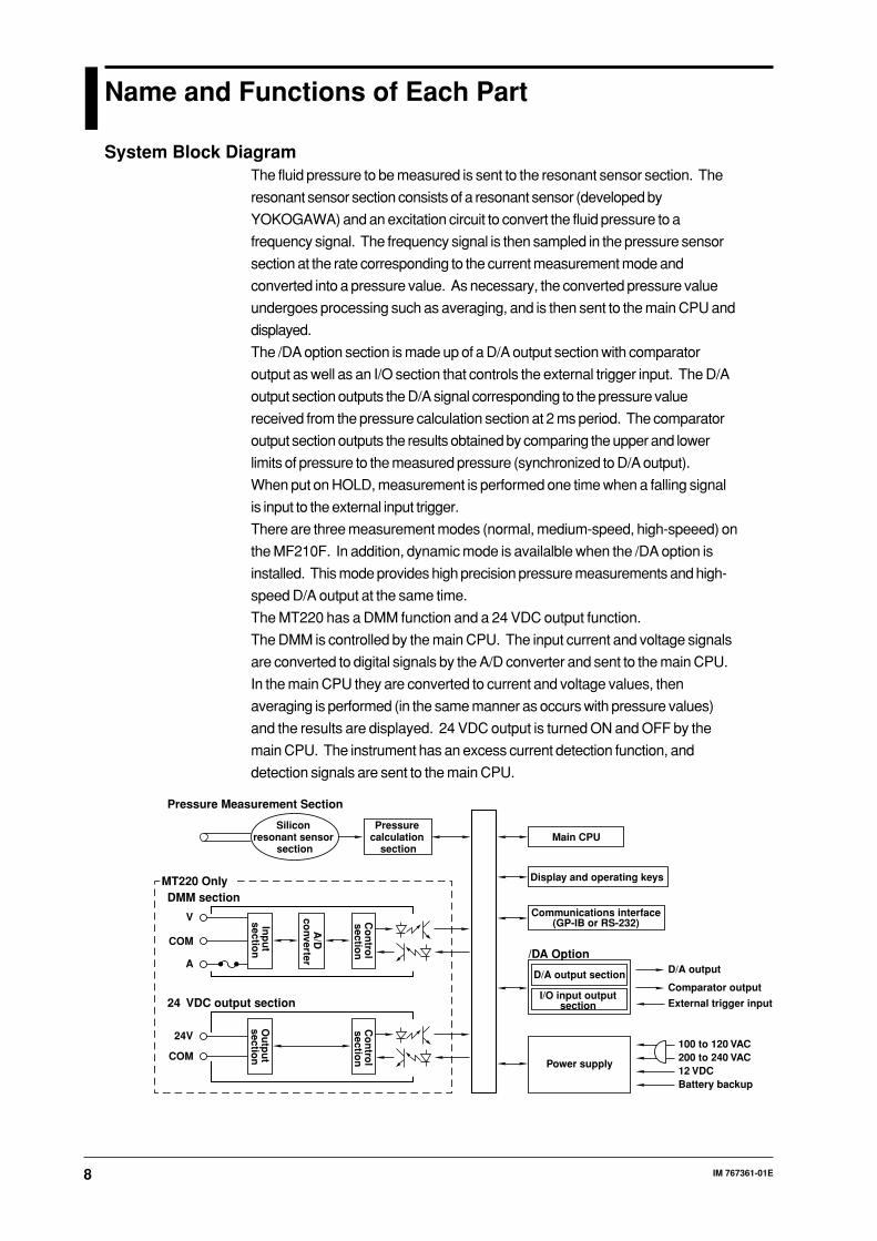
System Block DiagramThe fluid pressure to be measured is sent to the resonant sensor section. The
resonant sensor section consists of a resonant sensor (developed by
YOKOGAWA) and an excitation circuit to convert the fluid pressure to a
frequency signal. The frequency signal is then sampled in the pressure sensor
section at the rate corresponding to the current measurement mode and
converted into a pressure value. As necessary, the converted pressure value
undergoes processing such as averaging, and is then sent to the main CPU and
displayed.
The /DA option section is made up of a D/A output section with comparator
output as well as an I/O section that controls the external trigger input. The D/A
output section outputs the D/A signal corresponding to the pressure value
received from the pressure calculation section at 2 ms period. The comparator
output section outputs the results obtained by comparing the upper and lower
limits of pressure to the measured pressure (synchronized to D/A output).
When put on HOLD, measurement is performed one time when a falling signal
is input to the external input trigger.
There are three measurement modes (normal, medium-speed, high-speeed) on
the MF210F. In addition, dynamic mode is availalble when the /DA option is
installed. This mode provides high precision pressure measurements and high-
speed D/A output at the same time.
The MT220 has a DMM function and a 24 VDC output function.
The DMM is controlled by the main CPU. The input current and voltage signals
are converted to digital signals by the A/D converter and sent to the main CPU.
In the main CPU they are converted to current and voltage values, then
averaging is performed (in the same manner as occurs with pressure values)
and the results are displayed. 24 VDC output is turned ON and OFF by the
main CPU. The instrument has an excess current detection function, and
detection signals are sent to the main CPU.
DMM section
Pressure Measurement Section
Pressure calculation
sectionMain CPU
Display and operating keys
Power supply
Communications interface(GP-IB or RS-232)
D/A output section
/DA OptionD/A output
Comparator output
External trigger input
100 to 120 VAC200 to 240 VAC12 VDCBattery backup
I/O input output section
Silicon resonant sensor
section
V
COM
A
Inp
ut
section
24 VDC output section
24V
COM
MT220 Only
A/D
co
nverter
Co
ntro
l sectio
n
Ou
tpu
t sectio
n
Co
ntro
l sectio
n

9IM 767361-01E
Nam
e and
Fu
nctio
ns o
f Each
Part
Power Supply and Power Switch
This instrument can be operated from three different kinds of power supply,
commercial power, DC power (10 to 15 VDC), and battery pack (optional).
To operate the instrument using commercial power, turn ON both the MAIN
POEWR switch (rear panel) and POWER switch (front panel). In most cases,
you should always leave the MAIN POWER switch ON, and turn the power ON
or OFF using the POWER switch only.
To operate the instrument using DC power, turn the power ON or OFF using the
POWER switch only. It does not matter whether the MAIN POWER switch is
ON or OFF.
When operating the instrument using the battery pack, turn the power ON or
OFF using the POWER switch only.
If commercial power is supplied to the instrument and the MAIN POWER switch
is ON, the batteries will be trickle-charged. In trickle-charging, the batteries are
charged until natural discharge has been compensated for. Thus, to charge the
batteries completely, follow the operations on page 39, “Charging the Ni-Cd
Batteries.”
Switching power supply
Battery pack
Fuse
Battery charge/ discharge
control circuit
MAIN POWER switch
100 to 120 VAC200 to 240 VAC
12 VCD
Power Supply
DC/DC Converter
POWER switch
10 IM 767361-01E
FunctionsFunctions Common to the MT210, MT210F, and MT220
• Pressure Measurement (Gas and Liquid)
Measured values are displayed in 5-1/2 digits. They can also be displayed in
4-1/2 digits (the lowest digit is masked).
However, with the 700 kPa model (767355, 767365, 767373, and 767385),
measured values are displayed only in 4-1/2 digits (or 3-1/2 digits when the
lowest digit is masked).
• Zero Calibration
In order to maintain measurement accuracy, corrections are made to
compensate for the effects caused by changes in temperature and
installation environment.
• Communications Function (GP-IB or RS-232)
Remote control and acquisition of measured data can be performed via the
specified communications interface (GP-IB or RS-232).
• Data Hold
Stops acquisition of data and puts the displayed data on hold.
• Relative Display
Pressure is displayed as relative values.
• Averaging Function
Turns ON/OFF averaging for pressure data. Response times differ as shown
below depending on whether averaging is ON or OFF.
Averaging ON: 2.5 s or less (5 s or less for the 767370).
Averaging OFF: 1 s or less.
• Three Types of Power Supply
The instrument can be operated by commercial power (100 to 120 VAC, 200
to 240 VAC), DC power (10 to 15 VDC), or external battery pack (optional).
• Key Lock
Locks the ZERO CAL key, or all keys except the MENU and LIGHT keys.
11IM 767361-01E
Nam
e and
Fu
nctio
ns o
f Each
Part
MT210F Only
• Three Measurement Modes
With the three measurement modes (normal, medium-speed, and high-
speed), you can perform highly precise pressure measurements with rapid
response.
• Dynamic Mode (/DA option Only)
When dynamic mode is ON, you can achieve D/A output with fast response
regardless of the measurement mode. This allows high-speed D/A output
while displaying the data in highly precise normal measurement mode.
MT220 Only
• DMM Function (DCV, DCA Measurement)
Measurement of voltage (1 to 5 V) and current (4 to 20 mA) is possible, and
measured values are displayed in 4-1/2 digits.
A fuse is provided in each current terminal to protect against excessive
current.
• 24 VDC Power Supply
Floating output. The maximum output is 24 V/30 mA.
• Input % Display
Pressure: Displayed as a percentage relative to the specified full scale
setting.
Current/Voltage:Displayed as a percentage with 1 to 5 V or 4 to 20 mA as
0% to 100%.
• Error Display (%ERROR)
The difference between the measured current or voltage (%) and the input
pressure (%) is displayed as a percentage (%).
• Data Storage
Up to 2000 data can be stored in the internal memory.
/DA Option
• D/A output
D/A output allows you to output measured pressure data at ±2 V or ±5 V.
• Comparator Output
Compares measured pressure data (D/A output value) to a reference value
and outputs the results as a TTL level.
12 IM 767361-01E
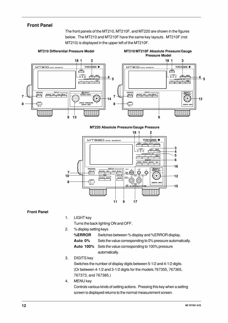
Front PanelThe front panels of the MT210, MT210F, and MT220 are shown in the figures
below. The MT210 and MT210F have the same key layouts. MT210F (not
MT210) is displayed in the upper left of the MT210F.
14 12
54
1
13
3
54
11818 3
9 9
MT210 Differential Pressure Model
HL
DIGITAL MANOMETER
PRESSURE
ZERO CAL RELATIVE UNIT HOLD TRIG
POWER
DISPLAY
LIGHT
COMP DIGITSHI IN LO
ENTER/LOCAL
MENU
PARAMETER SET
INPUTRANGE:10kPa
STATIC PRESSURE500kPa MAX
MT210/MT210F Absolute Pressure/Gauge Pressure Model
DIGITAL MANOMETER
PRESSURE
ZERO CAL RELATIVE UNIT HOLD TRIG
POWER
DISPLAY
LIGHT
COMP DIGITSHI IN LO
ENTER/LOCAL
MENU
PARAMETER SET
INPUTRANGE:10kPa
500kPa MAX8
7
8
7
DIGITAL MANOMETER
PRESSURE
ZERO CAL RELATIVE UNIT
DC5V/20mA ON/OFF ON/OFF
ALL TERMINALS 42V PEAK MAXBETWEEN TERMINALS AND GND.
FUSE250V
T 100mA
24VOUTPUT
24mA 6VMAX MAX
30mAMAX
HOLD TRIG
INPUT A COM
COM
V
POWER
DISPLAY
DMM 24V DC
LIGHT
COMP
MEMORY
DIGITS
STORE RECALL DELETE No.
HI IN LO
ENTER/LOCAL
MENU
PARAMETER SET
INPUTRANGE:10kPa
500kPa MAX
MT220 Absolute Pressure/Gauge Pressure
% Error AUTO 0% AUTO 100%
1 2
3456
7
8
9
10
11
12
15
16
17
18
Front Panel
1. LIGHT key
Turns the back lighting ON and OFF.
2. % display setting keys
%ERROR Switches between % display and %ERROR display.
Auto 0% Sets the value corresponding to 0% pressure automatically.
Auto 100% Sets the value corresponding to 100% pressure
automatically.
3. DIGITS key
Switches the number of display digits between 5-1/2 and 4-1/2 digits.
(Or between 4-1/2 and 3-1/2 digits for the models 767355, 767365,
767373, and 767385.)
4. MENU key
Controls various kinds of setting actions. Pressing this key when a setting
screen is displayed returns to the normal measurement screen.

13IM 767361-01E
Nam
e and
Fu
nctio
ns o
f Each
Part
5. PARAMETER SET keys
Selects parameters to be set, and increments the active
(blinking) digit.
Selects parameters to be set, and decrements the active
(blinking) digit.
Changes the active digit.
ENTER/ Enters the selected values.
LOCAL Clears remote mode.
6. MEMORY keys
STORE Stores data in the internal memory.
RECALL Recalls data from the internal memory.
DELETE Deletes data from the internal memory.
No. Designates the memory number to which data is to be stored or
from which it is to be recalled.
7. ZERO CAL (Zero Calibration) key
Performs zero pressure calibration.
8. POWER switch
Turns the power ON and OFF during daily operation.
9. DISPLAY keys
RELATIVE Displays pressure as a relative value.
UNIT Switches the unit of measured pressure.
HOLD Stops acquisition of data and puts the displayed data on
hold.
TRIG The trigger is activated once while the data is on hold.
10. DMM keys
DC5 V/20 mASelects whether voltage or current is to be measured.
ON/OFF Selects whether the DMM function is to be used or not.
11. 24 V output key
Turns 24 V output ON and OFF.
12. Pressure input port
A pressure input port is also provided on the rear panel, but it is not
possible to use both ports at the same time.
13. Pressure input port (Low)
A pressure input port is also provided on the rear panel, but it is not
possible to use both ports at the same time.
14. Pressure input port (High)
A pressure input port is also provided on the rear panel, but it is not
possible to use both ports at the same time.
15. Voltage input terminal
For measuring voltage using the DMM function.
16. Current input terminal
For measuring current using the DMM function.
17. 24 VDC output connector
Supplies 24 VDC.
18. Comparator monitor LED (/DA option only)
Displays the results from the comparator function.
Displays the result of the comparator function.
14 IM 767361-01E
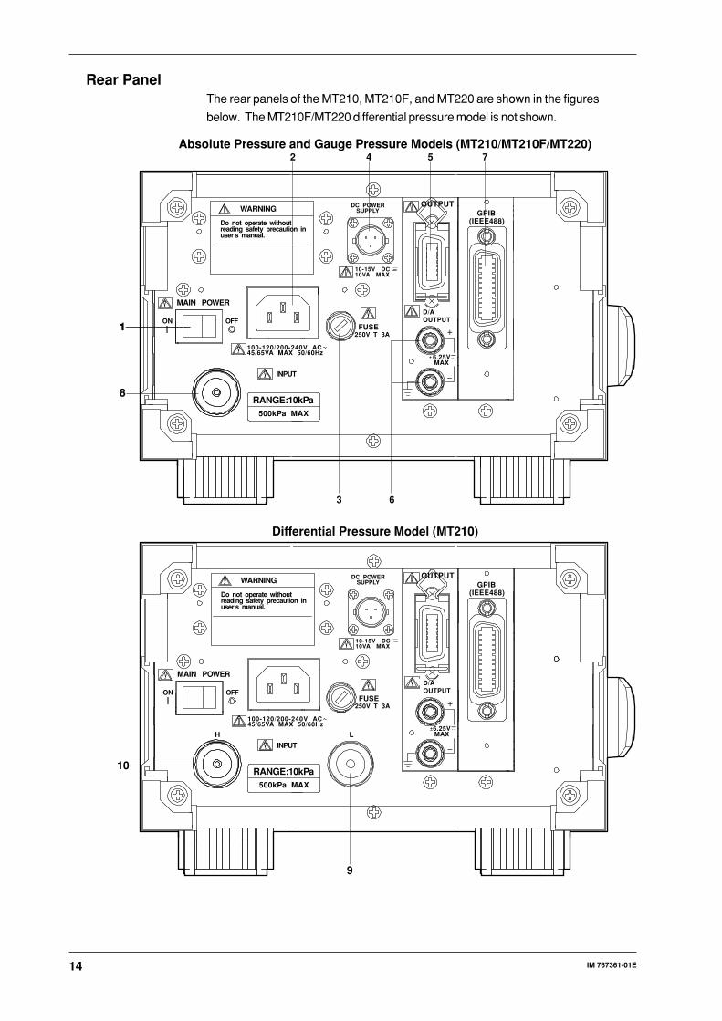
Rear PanelThe rear panels of the MT210, MT210F, and MT220 are shown in the figures
below. The MT210F/MT220 differential pressure model is not shown.
ON OFF
INPUT
MAIN POWER
RANGE:10kPa500kPa MAX
WARNING DC POWERSUPPLY
10-15V DC10VA MAX
FUSE
(IEEE488)GPIB
250V T 3A
100-120/200-240V AC45/65VA MAX 50/60Hz
Do not operate without reading safety precaution inuser s manual.
OUTPUT
D/AOUTPUT
6.25VMAX
2 4 5 7
1
63
Absolute Pressure and Gauge Pressure Models (MT210/MT210F/MT220)
8
1
LH
(IEEE488)GPIB
ON OFF
INPUT
MAIN POWER
RANGE:10kPa500kPa MAX
WARNING DC POWERSUPPLY
10-15V DC10VA MAX
FUSE250V T 3A
100-120/200-240V AC45/65VA MAX 50/60Hz
Do not operate without reading safety precaution inuser s manual.
6.25V
OUTPUT
D/AOUTPUT
MAX
Differential Pressure Model (MT210)
10
9
15IM 767361-01E
Nam
e and
Fu
nctio
ns o
f Each
Part
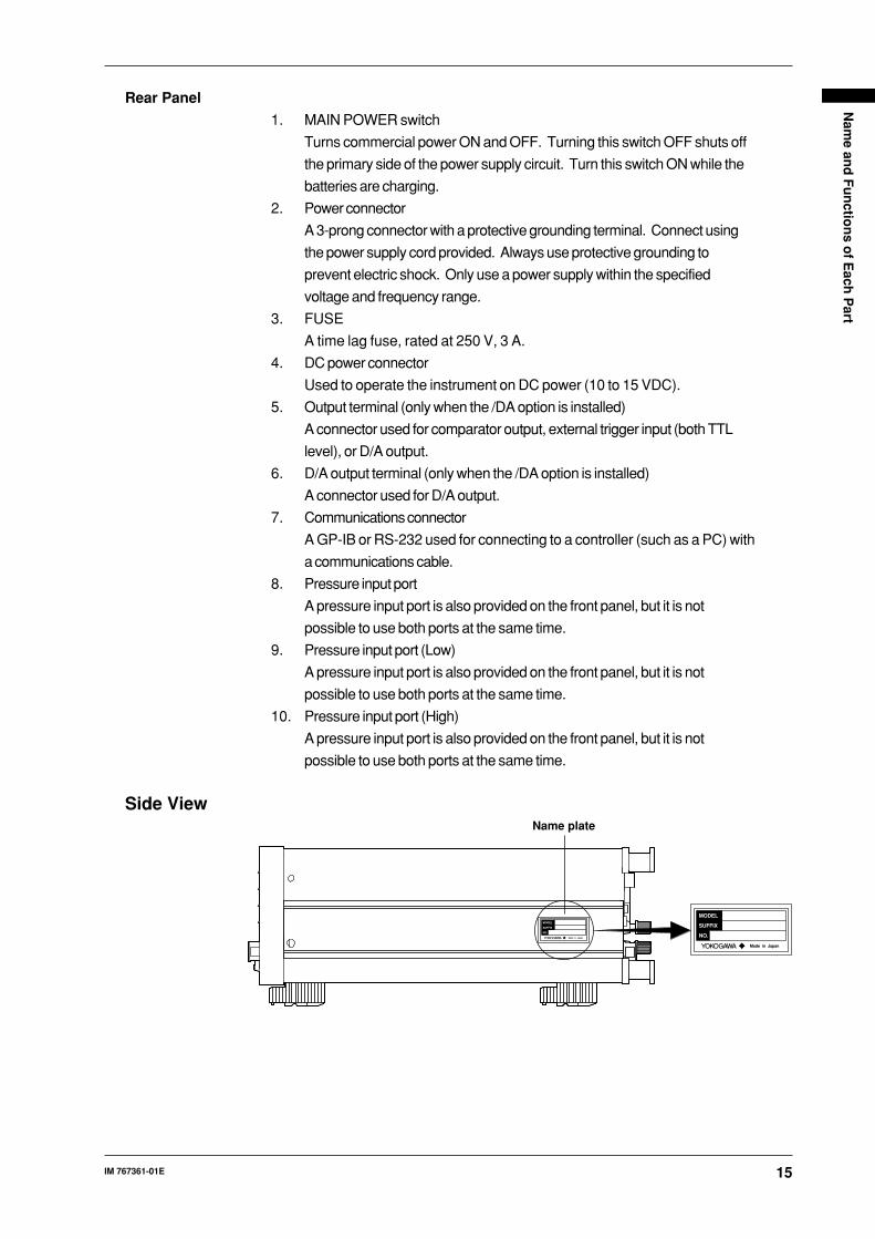
Rear Panel
1. MAIN POWER switch
Turns commercial power ON and OFF. Turning this switch OFF shuts off
the primary side of the power supply circuit. Turn this switch ON while the
batteries are charging.
2. Power connector
A 3-prong connector with a protective grounding terminal. Connect using
the power supply cord provided. Always use protective grounding to
prevent electric shock. Only use a power supply within the specified
voltage and frequency range.
3. FUSE
A time lag fuse, rated at 250 V, 3 A.
4. DC power connector
Used to operate the instrument on DC power (10 to 15 VDC).
5. Output terminal (only when the /DA option is installed)
A connector used for comparator output, external trigger input (both TTL
level), or D/A output.
6. D/A output terminal (only when the /DA option is installed)
A connector used for D/A output.
7. Communications connector
A GP-IB or RS-232 used for connecting to a controller (such as a PC) with
a communications cable.
8. Pressure input port
A pressure input port is also provided on the front panel, but it is not
possible to use both ports at the same time.
9. Pressure input port (Low)
A pressure input port is also provided on the front panel, but it is not
possible to use both ports at the same time.
10. Pressure input port (High)
A pressure input port is also provided on the front panel, but it is not
possible to use both ports at the same time.
Side View
MODEL
NO.
SUFFIX
Made in Japan
MODEL
NO.
SUFFIX
Made in Japan
Name plate
16 IM 767361-01E
Before Starting Measurement
Precautions During UseSafety Precautions
• If you are using this instrument for the first time, make sure to thoroughly
read the safety precautions given on page 2.
• Do not remove the cover from the instrument.
Some parts of the instrument carry high voltages and are extremely
dangerous. When the instrument needs internal inspection or adjustment,
contact your dealer or nearest YOKOGAWA representative as listed on the
back cover of this manual.
• If you notice smoke or unusual odors coming from the instrument, turn both
the POWER and MAIN POWER switches OFF and unplug the power cord
immediately. Also turn OFF the power to the measuring object connected to
the input section of the instrument. Contact your dealer or nearest
YOKOGAWA representative as listed on the back cover of this manual.
• If you use a 3-prong to 2-prong adapter to connect the power cord to a 2-
prong AC outlet, make sure that the grounding wire of the adapter is
grounded properly. For details, refer to page 18.
• Nothing should be placed on the power cord, and it should be kept away from
any heat sources. When unplugging the power cord from the AC outlet,
never pull the cord itself. Always hold the plug and pull it. If the power cord
is damaged, contact your dealer. Refer to page 5 for the part number to
reference when placing an order.
General Handling Precautions
• When moving the instrument, disconnect the power cord and connecting
cables. Always carry the instrument by the handle located on the left side of
the instrument.
• Keep electrically charged objects away from the input or output terminals.
They may damage the internal circuits.
• Do not allow volatile chemicals, or rubber or vinyl products to come into
contact with the case or operation panel for prolonged periods. Doing so
may result in discoloration.
• Take care not to allow any hot items such as a soldering iron to come into
contact with the operation panel.
• When the instrument is not going to be used for a long period, unplug the
power cord from the AC outlet.
• For precautions when handling the battery pack, refer to page 39, “Battery
Pack (Optional).”
• When removing dirt from the case or operation panel, first remove the power
cord, then use a clean, dry cloth to gently wipe the external surfaces of the
instrument. Do not use any solvents such as benzene or paint thinner.
Doing so might cause discoloration or deformation.
17IM 767361-01E
Befo
re Startin
g M
easurem
ent
Operating ConditionsThe instrument must be used in a place where the following conditions are met.
Ambient Temperature and Humidity
• Ambient temperature: 5 to 40°C (10 to 35°C for the 767370).
To ensure high measurement accuracy, the ambient
temperature should be 23 ± 3°C.
• Ambient humidity: 20% to 80% RH, with no condensation present.
Note• Internal condensation may occur if the temperature changes rapidly or if the instrument is
moved to a new location where both the ambient temperature and humidity are higher. If the
instrument is moved, allow it to acclimatize to its new environment for at least one hour before
starting operation.
• Never use the instrument in a place where it may be exposed to direct sunlight, otherwise the
temperature of the instrument will rise higher than the ambient temperature.
Never Use the Instrument in the Following Places
• Near heat sources
• Where an excessive amount of soot, steam, dust, or corrosive gases are
present
• Near strong magnetic field sources
• Near high voltage equipment or power lines
• Where there is a high level of mechanical vibration
• On an unstable surface
• At an altitude exceeding 2000 meters
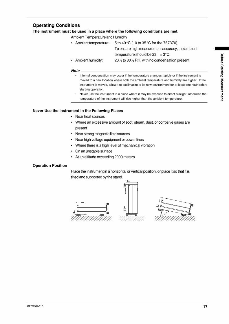
Operation Position
Place the instrument in a horizontal or vertical position, or place it so that it is
tilted and supported by the stand.

18 IM 767361-01E
Supplying AC PowerConnecting the Power Cord
Make sure that you perform the following steps before connecting the power.
Failure to do so may cause an electric shock or cause damage to the
instrument.
WARNING
• Connect the power cord only after confirming that the voltage of the
power supply matches the rated electric power voltage for theinstrument.
• Connect the power cord after confirming that both the MAIN POWER
switch (rear panel) and the POWER switch (front panel) are OFF.• To prevent electric shock or fire, use only the power cord and 3-prong
to 2-prong adapter supplied with this instrument.
• Always use protective grounding to prevent electric shock. Connect thepower cord to a 3-prong power outlet with a grounding terminal. Shouldthe instrument be connected to a 2-prong AC outlet, use the 3-prong to
2-prong adapter supplied with the instrument. Be sure to connect thegrounding wire (green) from the adapter to the grounding terminal onthe AC outlet.
• Only use an extension cord that has protective grounding, otherwisethe protection feature will be rendered ineffective.
Power Rating
Rated supply voltage range : 100 to 120 VAC/220 to 240 VAC
Permitted supply voltage range : 90 to 132 VAC/180 to 264 VAC
Rated supply voltage frequency : 50/60 Hz
Permitted supply voltage frequency range : 47 to 63 Hz
Power consumption (pressure measurement only)
: 25 VA MAX (100 VAC)
: 40 VA MAX (200 VAC)
Power consumption (pressure measurement + DMM + 24V output + charging
time)
: 45 VA MAX (100 VAC)
: 65 VA MAX (200 VAC)

19IM 767361-01E
Befo
re Startin
g M
easurem
ent
Supplying DC PowerConnecting the Power Cord
The pin assignment of the external DC power connector is shown below. Use a
cord that matches the DC power to be used.
(-) (+)1 3
2
(-)
NotePins 1 and 2 are short-circuited internally.
Power Rating
Rated supply voltage range : 10 to 15 VDC
Permitted supply voltage range : 9 to 16.5 VDC
Maximum power consumption : 10 VA MAX
WARNING
• To prevent electric shock, use a power supply not exceeding 60 VDC.
CAUTION
• Never short-circuit the terminals.• If a DC voltage exceeding the permitted supply voltage range is input to
the instrument, damage may result.• The number 1 and 2 connector pins of the external DC power supply
have the same electric potential as the meter case. Do not connect a
floating power supply.• Do not supply AC power when a DC power supply is used. It may
damage the instrument.
Turning the Power Switch ON/OFFTo Be Checked before Turning the Power ON
• Check that the instrument is correctly installed as described on page 17,
“Operation Position.”
• Check that the power supply specification to be used matches the one
specified for the power cord. Refer to “SUFFIX (Suffix Code)” on page 4.
• Is the proper power is being supplied? See page 18, “Power Rating”
See page 39, “Battery Pack”
Location of the Power Switches
There are two power switches. One is the MAIN POWER switch which is
located on the rear panel. The other is the POWER switch located at the lower
left corner of the front panel. For a description of the differences between these
switches, refer to page 9, “Power Supply and Power Switch.”

20 IM 767361-01E
Turning the Power ON/OFF
MAIN POWER Switch on Rear Panel
Press the ON side of the switch. This operation is not necessary if the
instrument is operated using DC power or the battery pack.
POWER Switch on Front Panel
This is a push-button type switch and the power is turned ON and OFF
alternately as the switch is pressed.
Note• When operating under DC power or the battery pack an indicator is displayed in the
upper part of the screen.
• When starting up using DC power or the battery back, the GP-IB and D/A output functions are
turned off.
• If the power is cut while the power switch is turned ON, the instrument may not start up
properly. If this happens, turn the power switch OFF, then back ON again.
• The warm-up time required to satisfy all specifications is approximately five minutes.
Response at Power OFF
Settings made prior to turning OFF the power are backed up. Thus, the
instrument will be setup using these saved settings the next time the power is
turned ON. However, some settings are not backed up. For details, refer to
page 22, “Default Settings (on Shipment from the Factory).”
NoteThe settings are backed up by lithium batteries. The batteries last for approximately five years
if they are used at an ambient temperature of 23°C. If the batteries run out, the data stored in
the internal memory will be lost when the power is turned OFF. If the batteries appear to be
running out, they need to be replaced immediately. The batteries cannot be replaced by the
user. Contact your nearest YOKOGAWA representative as listed on the back cover of this
manual.
Response and Display at Power ON
The self-test starts automatically when the POWER switch is turned ON. The
self-test checks each memory location. If the check results are satisfactory, the
opening messages will appear as shown on the following page, and the
instrument will be ready for measurement.
If an error code appears at the end of the self-test, the instrument is not
functioning properly. In this case, turn both the POWER and MAIN POWER
switches OFF immediately and contact your dealer or nearest YOKOGAWA
representative. Give them the model name and serial number from the name
plate on the side panel, as well as any error codes that were displayed.
NoteIf an error code appears, refer to page 54, “Error Codes and Corrective Actions.”

21IM 767361-01E
Befo
re Startin
g M
easurem
ent
Opening Messages
All Segments Lit
Model Number
Version
With the /DA Option(starting up using AC power)
(Starting up using DC power or the battery pack)
Power Switch ON
When starting up with the GP-IB and battery pack, or using DC power
Model Number
Suffix Code (Units of Pressure, Communications Functions)
Ready for Measurement
With the GP-IB interface in addressable mode
With the GP-IB interface in talk-only mode
With the RS-232 interface in normal mode
With the RS-232 interface in talk-only mode

22 IM 767361-01E
Default Settings (On Shipment from the Factory)Item Default (Factory Setting) Backup*1
Functions Common to the MT210, MT210F, and MT220Pressure zero calibration value 0*2 YesUnits of pressure kPa YesNumber of display digits 5-1/2*3 YesRelative display OFF YesData hold OFF NoPressure averaging ON*5 YesBack lighting OFF NoKey lock mode OFF YesBeep ON/OFF ON YesHeader for output data Included*4 YesStatus byte interrupt setting 31*4 Yes
MT120 OnlyMeasurement mode Normal Yes(normal, medium-speed, high-speed)Dynamic mode (/DA option) OFF Yes
MT220 only0% pressure value 0 Yes100% pressure value Measuring range YesDMM function ON/OFF ON YesMeasuring object for DMM DC voltage (5 V range) YesDMM averaging ON Yes24 V output OFF NoStore mode Manual store mode YesStoring rate (auto store mode) Each time one data item is updated YesNumber of data stored (auto store mode) 20 YesStore memory no. 1*6 YesRecall memory no. 1*6 Yes
With GP-IBGP-IB mode Addressable mode*4 YesAddress 1*4 YesDelimiter 0 (CR + LF + EOI)*4 YesGP-IB ON/OFF OFF*7 No(when using DC or battery power)
With RS-232RS-232 mode Normal mode*4 YesHandshake mode 0*4 YesFormat 0*4 YesBaud rate 9600*4 YesDelimiter 0 (CR + LF)*4 Yes
/DA boardD/A output range (2V/5V) 2V YesComparator output ON/OFF OFF YesComparator lower limit 0 YesComparator upper limit Measuring range YesD/A board ON/OFF OFF*7 No(when using DC or battery power)
*1 Yes: Backed up No: Not backed up*2 Not initialized in the case of absolute pressure models (767357, 767367 and 767387).*3 4-1/2 digits in the case of the 700 kPa models (767355, 767365, 767373, and 767385).*4 Not initialized by the “RC” command since this setting is related to the communications interface
specifications.*5 Off on the 767370. The initial pressure sample rate is 4 s.*6 This value is not initialized since it is a critical value for the measured data memory function.*7 This value is not initialized since it is a critical value for power supply control when operating on
battery or DC power.
Initializing SettingsSettings can be reset to their defaults (i.e. reset to the factory settings) in the
following two ways.
• By holding down the ENTER/LOCAL when the power switch is turned ON
until the model name and version number are displayed.
• By sending the RC communications command from the controller.
23IM 767361-01E
Pressu
re Measu
remen
t
Pressure Measurement
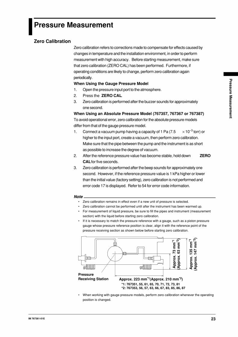
Zero CalibrationZero calibration refers to corrections made to compensate for effects caused by
changes in temperature and the installation environment, in order to perform
measurement with high accuracy. Before starting measurement, make sure
that zero calibration (ZERO CAL) has been performed. Furthermore, if
operating conditions are likely to change, perform zero calibration again
periodically.
When Using the Gauge Pressure Model
1. Open the pressure input port to the atmosphere.
2. Press the ZERO CAL.
3. Zero calibration is performed after the buzzer sounds for approximately
one second.
When Using an Absolute Pressure Model (767357, 767367 or 767387)
To avoid operational error, zero calibration for the absolute pressure models
differ from that of the gauge pressure model.
1. Connect a vacuum pump having a capacity of 1 Pa (7.5 × 10⁻³ torr) or
higher to the input port, create a vacuum, then perform zero calibration.
Make sure that the pipe between the pump and the instrument is as short
as possible to increase the degree of vacuum.
2. After the reference pressure value has become stable, hold down ZERO
CAL for five seconds.
3. Zero calibration is performed after the beep sounds for approximately one
second. However, if the reference pressure value is 1 kPa higher or lower
than the initial value (factory setting), zero calibration is not performed and
error code 17 is displayed. Refer to 54 for error code information.
Note• Zero calibration remains in effect even if a new unit of pressure is selected.
• Zero calibration cannot be performed until after the instrument has been warmed up.
• For measurement of liquid pressure, be sure to fill the pipes and instrument (measurement
section) with the liquid before starting zero calibration.
• If it is necessary to match the pressure reference with a gauge, such as a piston pressure
gauge whose pressure reference position is clear, align it with the reference point of the
pressure receiving section as shown below before starting zero calibration.
Ap
pro
x. 1
35 m
m*1
(Ap
pro
x. 1
47 m
m*2
)
Ap
pro
x. 7
3 m
m*1
(Ap
pro
x. 6
3 m
m*2
)
Approx. 223 mm*1(Approx. 210 mm*2)PressureReceiving Station
*1: 767351, 55, 61, 65, 70, 71, 72, 73, 81*2: 767353, 56, 57, 63, 66, 67, 83, 85, 86, 87
• When working with gauge pressure models, perform zero calibration whenever the operating
position is changed.
24 IM 767361-01E
• When working with absolute pressure models, zero calibration is very complex, so use the
relative function to correct errors if the operating position differs from that in which zero
calibration was performed.
• In the case of the absolute pressure model, zero calibration values cannot be changed by
initializing setup information using the RC communications command or the ENTER/LOCAL
after the power switch is turned ON.
• In the case of the absolute pressure model, zero calibration values are not initialized even if
error code 60 (set-up information back-up error) occurs. However, they are initialized after a
voltage drop in the back-up battery. In this case, error 63 will be displayed.
Input Function
CAUTION
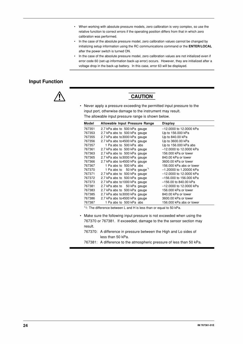
• Never apply a pressure exceeding the permitted input pressure to theinput port, otherwise damage to the instrument may result.The allowable input pressure range is shown below.
Model Allowable Input Pressure Range Display
767351 2.7 kPa abs to 500 kPa gauge –12.0000 to 12.0000 kPa767353 2.7 kPa abs to 500 kPa gauge Up to 156.000 kPa767355 2.7 kPa abs to3000 kPa gauge Up to 840.00 kPa767356 2.7 kPa abs to4500 kPa gauge Up to 3600.00 kPa767357 1 Pa abs to 500 kPa abs Up to 156.000 kPa abs767361 2.7 kPa abs to 500 kPa gauge –12.0000 to 12.0000 kPa767363 2.7 kPa abs to 500 kPa gauge 156.000 kPa or lower767365 2.7 kPa abs to3000 kPa gauge 840.00 kPa or lower767366 2.7 kPa abs to4500 kPa gauge 3600.00 kPa or lower767367 1 Pa abs to 500 kPa abs 156.000 kPa abs or lower767370 1 Pa abs to 50 kPa gauge*1 –1.20000 to 1.20000 kPa767371 2.7 kPa abs to 500 kPa gauge –12.0000 to 12.0000 kPa767372 2.7 kPa abs to 500 kPa gauge –156.000 to 156.000 kPa767373 2.7 kPa abs to1000 kPa gauge –156.00 to 840.00 kPa767381 2.7 kPa abs to 50 kPa gauge –12.0000 to 12.0000 kPa767383 2.7 kPa abs to 500 kPa gauge 156.000 kPa or lower767385 2.7 kPa abs to3000 kPa gauge 840.00 kPa or lower767386 2.7 kPa abs to4500 kPa gauge 3600.00 kPa or lower767387 1 Pa abs to 500 kPa abs 156.000 kPa abs or lower
*1: The difference between L and H is less than or equal to 50 kPa.
• Make sure the following input pressure is not exceeded when using the767370 or 767381. If exceeded, damage to the the sensor section mayresult.
767370: A difference in pressure between the High and Lo sides ofless than 50 kPa.
767381: A difference to the atmospheric pressure of less than 50 kPa.
25IM 767361-01E
Pressu
re Measu
remen
t
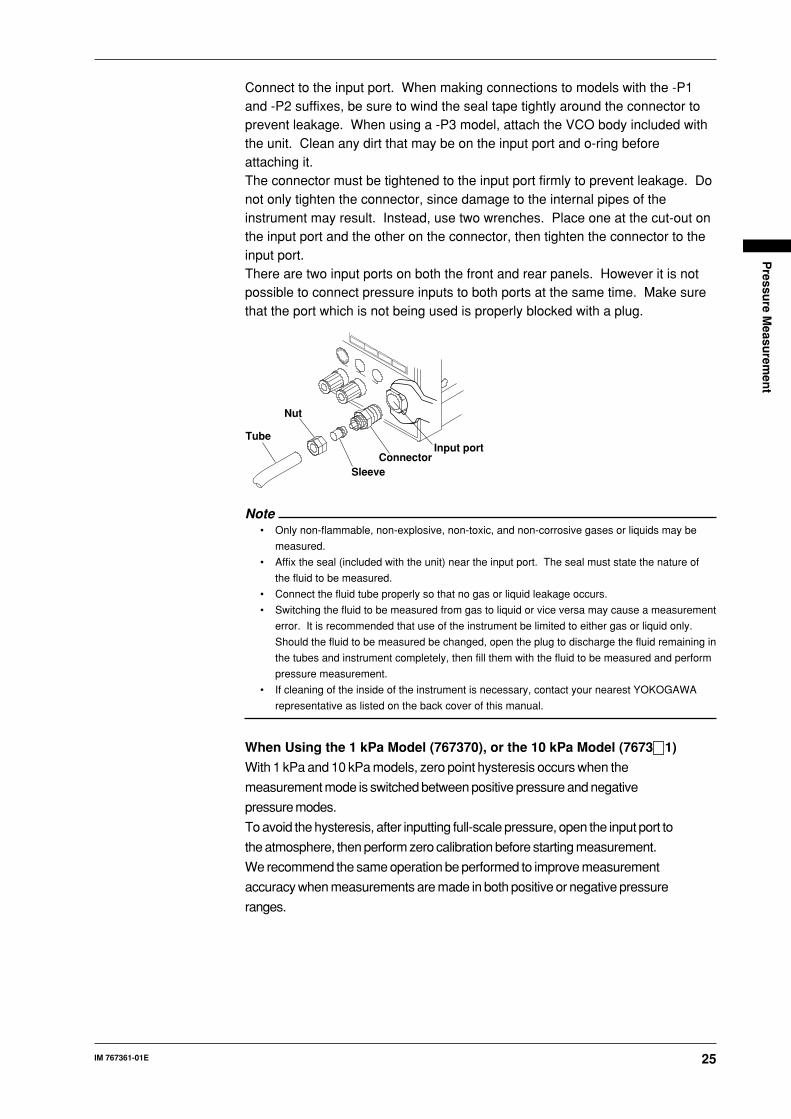
Connect to the input port. When making connections to models with the -P1and -P2 suffixes, be sure to wind the seal tape tightly around the connector toprevent leakage. When using a -P3 model, attach the VCO body included withthe unit. Clean any dirt that may be on the input port and o-ring beforeattaching it.The connector must be tightened to the input port firmly to prevent leakage. Donot only tighten the connector, since damage to the internal pipes of theinstrument may result. Instead, use two wrenches. Place one at the cut-out onthe input port and the other on the connector, then tighten the connector to theinput port.There are two input ports on both the front and rear panels. However it is notpossible to connect pressure inputs to both ports at the same time. Make surethat the port which is not being used is properly blocked with a plug.
Tube
Nut
SleeveConnector
Input port
Note• Only non-flammable, non-explosive, non-toxic, and non-corrosive gases or liquids may be
measured.
• Affix the seal (included with the unit) near the input port. The seal must state the nature of
the fluid to be measured.
• Connect the fluid tube properly so that no gas or liquid leakage occurs.
• Switching the fluid to be measured from gas to liquid or vice versa may cause a measurement
error. It is recommended that use of the instrument be limited to either gas or liquid only.
Should the fluid to be measured be changed, open the plug to discharge the fluid remaining in
the tubes and instrument completely, then fill them with the fluid to be measured and perform
pressure measurement.
• If cleaning of the inside of the instrument is necessary, contact your nearest YOKOGAWA
representative as listed on the back cover of this manual.
When Using the 1 kPa Model (767370), or the 10 kPa Model (7673 1)
With 1 kPa and 10 kPa models, zero point hysteresis occurs when the
measurement mode is switched between positive pressure and negative
pressure modes.
To avoid the hysteresis, after inputting full-scale pressure, open the input port to
the atmosphere, then perform zero calibration before starting measurement.
We recommend the same operation be performed to improve measurement
accuracy when measurements are made in both positive or negative pressure
ranges.

26 IM 767361-01E
Selecting the UnitsSelect the units of pressure using the UNIT key.
For -U1 models Pressing the UNIT does not change the units.
For -U2 models Pressing the UNIT switches the units in the order kPa,
kgf/cm 2, mmH2O, mmHg, kPa.
For -U3 models Pressing the UNIT switches the units in the order kPa, kgf/
cm2, mmH2O, mmHg, inH 2O, inHg, psi, kPa.
Note• The factory default units setting is kPa.
• Units cannot be switched when in % display or %ERROR display modes.
During normal measurement units are displayed as shown in the left column below.
However, when in % display mode they appear as shown in the right column, and only the
units for the current input pressure being % displayed are shown.
The same is true for the current and voltage display of the DMM function.
kPa kPa
kgf/cm2
mmH20
mmHg
% %
During normal measurement: using -U2 models % display mode
• Pressure calculation coefficient
1.0 kPa
9.806650E+1 kgf/cm2
9.806650E-3 mmH20
1.333224E-1 mmHg
2.490889E-1 inH20
3.386388 inHg
6.894757 psi
Selecting the Number of Display DigitsMeasured pressure values can be displayed with the lowest digit masked. This
is useful when the lowest digit flickers and is difficult to read.
Pressing DIGITS causes the lowest digit to be masked, and the display to show
4-1/2 digits. Pressing DIGITS a second time unmasks the lowest digit, and
causes the display to show 5-1/2 digits.
However with 700 kPa models (767355, 767365, 767373 and 767385),
measured values are displayed only in 4-1/2 digits without the mask, or 3-1/2
digits with the mask.Note
This also applies to % display of DMM (%ERROR display) if % display or %ERROR display
mode is active.
Relative DisplayWhen the RELATIVE key is pressed the difference between a reference
pressure and the pressure being measured is displayed.
1. Input the pressure to be used as the reference.
2. Press the RELATIVE.
3. RELATIVE is displayed as shown next page.
4. To cancel relative display, press the RELATIVE. RELATIVE disappears
from the screen.Note
While % or %ERROR display is active, relative display is inoperable even if the RELATIVE
key is pressed.
27IM 767361-01E
Pressu
re Measu
remen
t
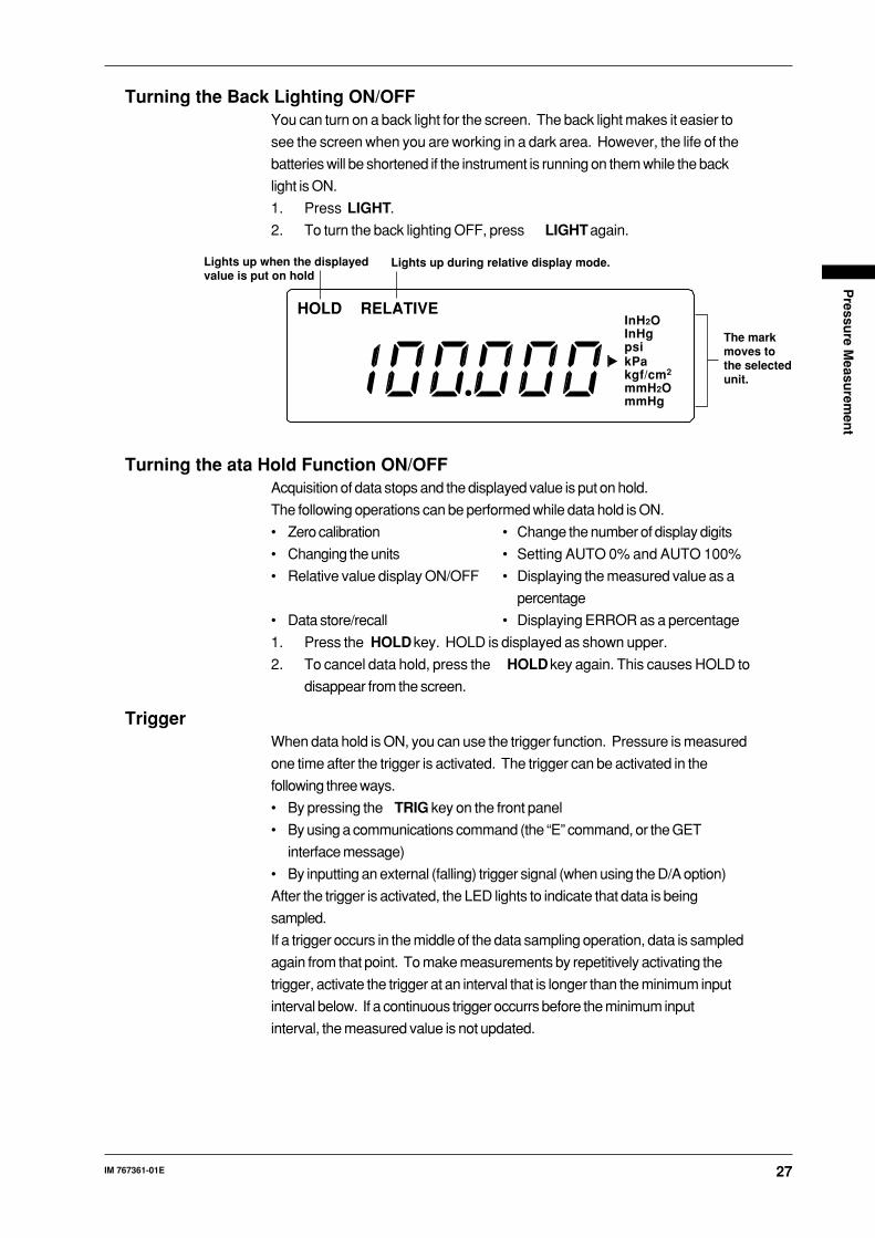
Turning the Back Lighting ON/OFFYou can turn on a back light for the screen. The back light makes it easier to
see the screen when you are working in a dark area. However, the life of the
batteries will be shortened if the instrument is running on them while the back
light is ON.
1. Press LIGHT.
2. To turn the back lighting OFF, press LIGHT again.
HOLD RELATIVE
kPapsiInHgInH2O
kgf/cm2
mmH2OmmHg
Lights up during relative display mode.Lights up when the displayedvalue is put on hold
The markmoves tothe selectedunit.
Turning the ata Hold Function ON/OFFAcquisition of data stops and the displayed value is put on hold.
The following operations can be performed while data hold is ON.
• Zero calibration • Change the number of display digits
• Changing the units • Setting AUTO 0% and AUTO 100%
• Relative value display ON/OFF • Displaying the measured value as a
percentage
• Data store/recall • Displaying ERROR as a percentage
1. Press the HOLD key. HOLD is displayed as shown upper.
2. To cancel data hold, press the HOLD key again. This causes HOLD to
disappear from the screen.
TriggerWhen data hold is ON, you can use the trigger function. Pressure is measured
one time after the trigger is activated. The trigger can be activated in the
following three ways.
• By pressing the TRIG key on the front panel
• By using a communications command (the “E” command, or the GET
interface message)
• By inputting an external (falling) trigger signal (when using the D/A option)
After the trigger is activated, the LED lights to indicate that data is being
sampled.
If a trigger occurs in the middle of the data sampling operation, data is sampled
again from that point. To make measurements by repetitively activating the
trigger, activate the trigger at an interval that is longer than the minimum input
interval below. If a continuous trigger occurrs before the minimum input
interval, the measured value is not updated.
28 IM 767361-01E
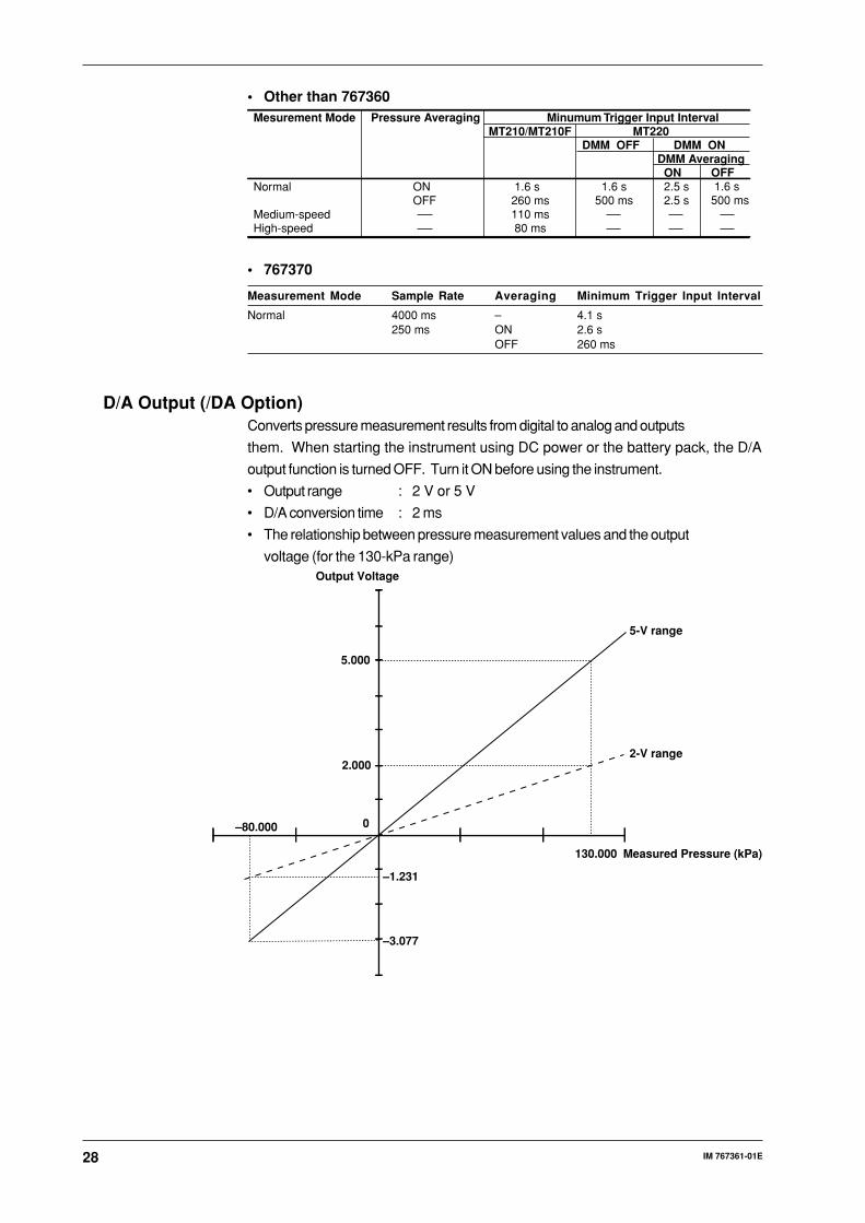
• Other than 767360Mesurement Mode
Normal
Medium-speedHigh-speed
Pressure Averaging
ON OFF
Minumum Trigger Input IntervalMT210/MT210F MT220
1.6 s 260 ms 110 ms 80 ms
DMM ONDMM Averaging ON 2.5 s 2.5 s
OFF 1.6 s500 ms
DMM OFF
1.6 s 500 ms
• 767370
Measurement Mode Sample Rate Averaging Minimum Trigger Input Interval
Normal 4000 ms – 4.1 s250 ms ON 2.6 s
OFF 260 ms
D/A Output (/DA Option)Converts pressure measurement results from digital to analog and outputs
them. When starting the instrument using DC power or the battery pack, the D/A
output function is turned OFF. Turn it ON before using the instrument.
• Output range : 2 V or 5 V
• D/A conversion time : 2 ms
• The relationship between pressure measurement values and the output
voltage (for the 130-kPa range)Output Voltage
Measured Pressure (kPa)130.000
5-V range
2-V range
–1.231
–3.077
5.000
2.000
–80.000 0
29IM 767361-01E
Pressu
re Measu
remen
t
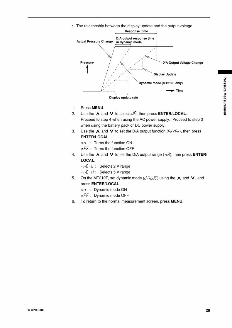
• The relationship between the display update and the output voltage.
Dynamic mode (MT210F only)
Pressure
Actual Pressure Change
Response time
Display Update
Time
D/A Output Voltage Change
D/A output response timein dynamic mode
Display update rate
1. Press MENU.
2. Use the and to select , then press ENTER/LOCAL.
Proceed to step 4 when using the AC power supply. Proceed to step 3
when using the battery pack or DC power supply.
3. Use the and to set the D/A output function ( ), then press
ENTER/LOCAL.
: Turns the function ON
: Turns the function OFF
4. Use the and to set the D/A output range ( ), then press ENTER/
LOCAL.
: Selects 2 V range
: Selects 5 V range
5. On the MT210F, set dynamic mode ( ) using the and , and
press ENTER/LOCAL.
: Dynamic mode ON
: Dynamic mode OFF
6. To return to the normal measurement screen, press MENU.
30 IM 767361-01E
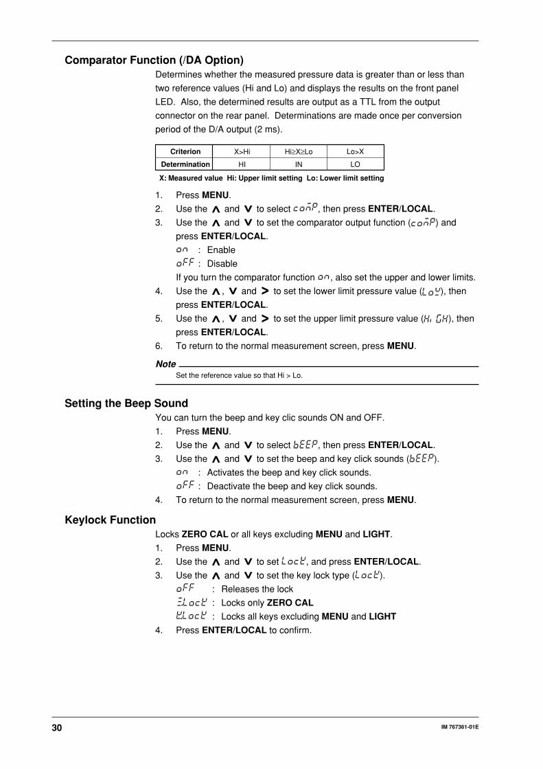
Comparator Function (/DA Option)Determines whether the measured pressure data is greater than or less than
two reference values (Hi and Lo) and displays the results on the front panel
LED. Also, the determined results are output as a TTL from the output
connector on the rear panel. Determinations are made once per conversion
period of the D/A output (2 ms).
Criterion
Determination
X>Hi
HI
Lo>X
LO
Hi≥X≥Lo
IN
X: Measured value Hi: Upper limit setting Lo: Lower limit setting
1. Press MENU.
2. Use the and to select , then press ENTER/LOCAL.
3. Use the and to set the comparator output function ( ) and
press ENTER/LOCAL.
: Enable
: Disable
If you turn the comparator function , also set the upper and lower limits.
4. Use the , and to set the lower limit pressure value ( ), then
press ENTER/LOCAL.
5. Use the , and to set the upper limit pressure value ( ), then
press ENTER/LOCAL.
6. To return to the normal measurement screen, press MENU.
NoteSet the reference value so that Hi > Lo.
Setting the Beep SoundYou can turn the beep and key clic sounds ON and OFF.
1. Press MENU.
2. Use the and to select , then press ENTER/LOCAL.
3. Use the and to set the beep and key click sounds ( ).
: Activates the beep and key click sounds.
: Deactivate the beep and key click sounds.
4. To return to the normal measurement screen, press MENU.
Keylock FunctionLocks ZERO CAL or all keys excluding MENU and LIGHT.
1. Press MENU.
2. Use the and to set , and press ENTER/LOCAL.
3. Use the and to set the key lock type ( ).
: Releases the lock
: Locks only ZERO CAL
: Locks all keys excluding MENU and LIGHT
4. Press ENTER/LOCAL to confirm.

31IM 767361-01E
Pressu
re Measu
remen
t
Setting the Measurement Mode• For the MT210
1. Press MENU.
2. Use the and to set , and press ENTER/LOCAL.
3. Use the and to set the pressure sample rate ( ) and press
ENTER/LOCAL (767370 only).
: 250 ms
: 4000 ms
4. Use the and to set the pressure moving average ( ) and
press ENTER/LOCAL.
: Enable pressure moving average.
: Disable pressure moving average
5. To return to the normal measurement screen, press MENU.
NoteIf you set the pressure sample rate to 4000 ms on the 767370, the pressure moving average
is fixed at OFF.
• For the MT210F
You can select from three different measurement modes, normal, medium-
speed, and high-speed.
1. Press MENU.
2. Use the and to select , then press ENTER/LOCAL.
3. Use the and to set the measurement mode ( ), then press
ENTER/LOCAL.
: Normal measurement mode
: Medium-speed measurement mode
: High-speed measurement mode
If you specified normal mode, proceed to step 4. If you specified
medium-speed or high-speed mode, proceed to step 5.
4. Use the and to set the pressure moving average ( ) and
press ENTER/LOCAL.
: Enable pressure moving average
: Disable pressure moving average
5. To return to the normal measurement screen, press MENU.
• For the MT220
1. Press MENU.
2. Use the and to select , then press ENTER/LOCAL.
3. Use the and to set the pressure moving average ( ), then
press ENTER/LOCAL.
: Enable pressure moving average
: Disable pressure moving average
4. Use the and to set the DMM moving average ( ), then
press ENTER/LOCAL.
: Enable DMM moving average
: Disable DMM moving average
5. To return to the normal measurement screen, press MENU.
32 IM 767361-01E
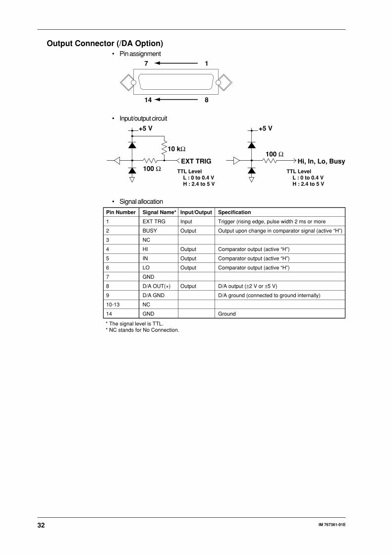
Output Connector (/DA Option)• Pin assignment
17
814
• Input/output circuit
+5 V +5 V
10 kΩ
100 Ω TTL LevelL : 0 to 0.4 VH : 2.4 to 5 V
EXT TRIG100 Ω
TTL LevelL : 0 to 0.4 VH : 2.4 to 5 V
Hi, In, Lo, Busy
• Signal allocation
* The signal level is TTL.* NC stands for No Connection.
Pin Number Signal Name* Input/Output Specification
1 EXT TRG Input Trigger (rising edge, pulse width 2 ms or more
2 BUSY Output Output upon change in comparator signal (active “H”)
3 NC
4 HI Output Comparator output (active “H”)
5 IN Output Comparator output (active “H”)
6 LO Output Comparator output (active “H”)
7 GND
8 D/A OUT(+) Output D/A output (±2 V or ±5 V)
9 D/A GND D/A ground (connected to ground internally)
10-13 NC
14 GND Ground

33IM 767361-01E
Ad
justin
g an
d C
alibratin
g th
e Differen
tial Pressu
re Tran
smitter u
sing
the M
T220
Adjusting and Calibrating the Differential PressureTransmitter using the MT220Connecting the Differential Pressure Transmitter to the MT220
To measure output from the differential pressure transmitter in terms of current,
connect the transmitter to the instrument and calibrate the transmitter.
differential pressure
transmitter
MT220
COM
A
COM
24Voutput terminalcurrent input terminal
WARNING
Including the internal electric potential, the maximum allowable
potential difference for all input/output and ground terminals is 42Vpeak. Ensure that the potential of each terminal does not exceed thefollowing values. If this value is exceeded, damage to the instrument
and injury to personnel may result.DMM measurement terminal: 18 Vpeak relative to ground.
CAUTION
• Do not apply an external voltage to the 24 VDC output connector.Doing so may damage the instrument.
• If the 24 VDC output terminals are short-circuited or the load current
exceeds the limit (approx. 40 mA), -OL- is displayed and the output isturned OFF.
• If the instrument is operated continuously from the Ni-Cd batteries with
the load current for the 24 VDC output exceeding 20 mA, the life of thebatteries will be shortened rapidly.
• Never apply a voltage exceeding the permitted maximum to the voltage
input terminals. Doing so may damage the instrument.Maximum permitted input voltage: 30 VDC
• Never apply a current exceeding the maximum permitted input current
to the current input terminals. Make sure that the fuse used meets thespecified rating. Only use a fuse of the specified rating. For details,refer to page 58.
Maximum permitted input current: 100 mADC
24 VDC Ouput1. Press 24 V DC ON/OFF.
2. 24 V will be displayed in the bottom right corner of the screen.
3. To stop 24 VDC output, press 24 V DC ON/OFF again. This causes 24 V
to disappear from the screen.Note
If the 24 VDC output becomes overloaded, -OL- will be displayed in the bottom right corner of
the screen, and the 24VDC output will be turned OFF automatically.
Press 24V DC ON/OFF to remove -OL- from the bottom right of the screen and go around the
cause of the overload, then restart 24 VDC output.

34 IM 767361-01E
DMM Function1. If nothing is displayed in the lower part of the screen, press the ON/OFF
under the DMM group to turn the DMM function ON.
2. Press DC5 V/20 mA to set the mark to either V or mA.
3. To cancel DMM measurement, press the ON/OFF under the DMM group
again to turn the DMM function OFF.Note
The display range for the measured values are shown below.
Voltage –6.0000 V to +6.0000 V
Current –24.000 mA to +24.000 mA
% DisplayIf 0% and 100% pressure values have been set, the measured values can be
displayed as a percentage (%) relative to these 0% and 100% values. 0% and
100% values can be set by directly entering a desired numerical value or by
applying actual pressure.
If % display mode is active during measurement of current or voltage using the
DMM function, the measured value is displayed as a percentage: 1 to 5 V or 4
to 20 mA being equivalent to 0 to 100%. The display range for pressure and
voltage/current values is shown below.
Pressure: ±999.99%. is displayed in the upper part of the screen if
the value exceeds the specified number of display digits.
Current/voltage: 0 to 24 mA/0 to 6 V (–25 to 125%). is displayed at
the lower part of the screen if the input exceeds this range.
Example
When 20 kPa is set as 0% and 100 kPa as 100%:
If the input pressure is 40 kPa, 25% will be displayed in the upper part of the
screen. 25% (8 mA) will also be displayed in the lower part of the screen if the
output current from the differential pressure transmitter is correct.100%
25
020 40 100 kPa
100%
37.525
04 8 10 20 mA
Setting 0% and 100% by Entering the Desired Numerical Value (Manual Setting)
1. Press MENU.
Use the and to select , then press ENTER/LOCAL to
activate the 0% pressure setting screen.
2. Use the , and to enter the value corresponding to 0%, then
press ENTER/LOCAL.
3. To set the value corresponding to 100% value, use the , and ,
then press ENTER/LOCAL.
4. Press MENU to return to the normal measurement screen.
5. Press the %ERROR to activate % display mode.

35IM 767361-01E
Ad
justin
g an
d C
alibratin
g th
e Differen
tial Pressu
re Tran
smitter u
sing
the M
T220
Setting 0% and 100% by Applying Actual Pressure (Automatic Setting)
1. Apply pressure which corresponds to 0%.
2. Press the Auto %.
3. Apply pressure which corresponds to 100%.
4. Press the Auto 100%.
5. Press the %ERROR key to activate % display mode.Note
• Any 0% and 100% pressure values can be set as long as they are within the display rangeand satisfy the condition 0% value < 100% value.
• If the applied pressure is outside the display range, it can be set as the 0% or 100% valueeven if the AUTO 0% or AUTO 100% has been pressed.
• If the 0% value is greater than the 100% value, will be displayed when the%ERROR is pressed. In this case, enter the correct 0% and 100% values.
• Automatic setting (using the AUTO 0% and AUTO 100%) is possible only when theinstrument is in normal measurement display mode.
• If the instrument is in relative display mode, % display will not be activated even if the%ERROR is pressed.
Error DisplayThe output voltage (or current) can be checked against the pressure input to the
differential pressure transmitter. The %ERROR value represents the value
obtained by subtracting the input pressure value displayed as a percentage
from the current/voltage value displayed as a percentage. .
The pressure values are shown under % display, and the DMM values are
shown under %ERROR display.
Example When 20 kPa is set as 0% and 100 kPa as 100%:
When the applied pressure is 40 kPa, 0% (25 - 25) will be displayed as the
%ERROR if the current is 8 mA, and 12.5% (37.5 - 25) will be displayed as
%ERROR if the current is 10 mA.
1. Make the necessary settings for % display (Refer to the diagram of the
previous page).
2. Press the %ERROR to activate %ERROR display mode.Note
• If the %ERROR key is pressed to activate % display mode, the value measured by the DMMfunction is also displayed as a percentage. However, this does not apply if the DMM functionis OFF.
• The display switches as follows each time the %ERROR key is pressed.DMM function ON: normal measurement display→% display→%ERROR display→normal
measurement displayDMM function OFF: normal measurement display→% display→normal measurement display
kPa
%
VmA%
24V -OL -Error
100%
Lit during an overload
Lit during 24 V output
Mark indicates selected units
Lit during %ERRORdisplayLit when AUTO 0, 100% is set
36 IM 767361-01E
Storing and Recalling Data (MT220 Only)
Storing DataAcquired data is assigned a specific memory number and then stored in the
internal memory.
1 to 9999 can be set as the data number (memory number). If no destination
memory number is specified, data will be stored under consecutive memory
numbers (default starting number is 1). When a memory number is specified,
data is saved successively starting with that number.
Two types of storage methods are available, auto store and manual store.
Data acquisition interval
(number of samples taken per stored data item): 1, 4, 16, 64, 512
No. of storage times: 1 to 2000
Destination memory No.: 1 to 9999
No. of data which can be stored: 2000
Auto Store
Data is stored automatically the specified number of times and at the specified
interval. If no destination memory number is specified, storage starts from the
memory number after the one in which last data item was stored.
Making Auto Store Settings
1. Press MENU.
2. Keep pressing or until is displayed in the screen, then
press ENTER/LOCAL to proceed to the store mode setting screen.
3. Press or to display , then press ENTER/LOCAL to select the
mode.
4. In the store rate setting screen ( ), use and to select the
desired acquisition interval, then press ENTER/LOCAL.
5. In the screen to set the number of data ( ), use , and to
set the number of data to be stored, then press ENTER/LOCAL.
6. To return to the normal measurement screen, press MENU.
Setting the Memory Number at Which Storage Is to Be Started
7. Press No. to display the memory number setting screen ( ).
8. Use , and to set the desired memory number, then press ENTER/
LOCAL.
Storing Data
9. Pressing STORE automatically stores data items one by one. The current
memory number to which data is being stored is displayed for
approximately 0.5 seconds in the upper part of the screen.
Data automatically ceases to be stored when the stored number of data
reaches the specified maximum number. Then is displayed in the
upper part of the screen and in the lower part of the screen for
approximately 0.5 seconds.
Stopping Auto Store
10. Press STORE again. Auto store stops. is displayed in the upper
part of the screen and in the lower part of the screen for
approximately 0.5 seconds.Note
The store mode, store rate, and allowed number of stores cannot be changed during auto store.
37IM 767361-01E
Sto
ring
and
Recallin
g D
ata (MT
220 On
ly)
Manual Store
Pressing the STORE key stores data. If no destination memory number is
specified, the data is stored under the memory number immediately following
the one in which the last data item was stored.
Making Manual Store Settings
1. Press MENU.
2. Keep pressing or until is displayed in the screen, then
press ENTER/LOCAL to proceed to the store mode setting screen.
3. Press or to display , then press ENTER/LOCAL to select the
mode.
4. To return to the normal measurement screen, press MENU.
5. Press No. to display the memory number setting screen ( ).
6. Use , and to set the desired memory number, then press
ENTER/LOCAL.
Storing Data
7. Pressing STORE stores data and displays in the upper part of the
screen, while the memory number to which the data is being stored is
displayed in the lower part of the screen for approximately 0.5 seconds.Note
• It is not possible to overwrite data. If a destination memory in which data already exists is
selected, error code will be displayed, indicating that overwriting is not possible. In auto
store, error code is displayed and auto store stops automatically when a memory
number in which data already exists is reached. If you want to store data in a memory in
which data already exists, delete the existing data first, then store the new data.
• All data stored in the internal memory will be backed up even if the power is turned OFF.
Data RecallData stored in the internal memory can be recalled. Specify the number of the
data items you want to recall.
The set-up information which was in effect when the last store was performed
will be restored when a recall is performed.
• Relative value display ON/OFF
• DMM function ON/OFF, selected measurement item (current or voltage)
• Pressure values specified as 0% and 100% in the case of % display
When recall mode is cleared, the settings which were effective before the recall
will be restored.
Recall Mode
RECALL is displayed during recall mode.
1. Press RECALL.
RECALL lights up on the screen, indicating that recall mode is now active
and the latest stored data is recalled.
Recalling Data Sequentially
2. When you press or while in recall mode, the number of the data to
be recalled is incremented or decremented, and the corresponding data
will be recalled.
3. To cancel recall mode, press RECALL again. RECALL disappears from
the screen.
38 IM 767361-01E
Recalling Data by Specifying the Corresponding Memory Number
2. Press No. while recall mode is active.
3. Use , , or to select the desired memory number.
4. Press ENTER/LOCAL to recall the data.
5. To cancel recall mode, press RECALL again. RECALL disappears from
the screen.Note
• If recall is performed from a memory number in which no data has been stored, error code
will be displayed, and the screen will appear.
• If the desired data is relative display data, it cannot be recalled if % display or %ERROR
display is active. In this case, display is switched automatically to the normal display screen.
Deleting DataData stored in the internal memory can be deleted. Two methods are available;
one is used to delete the desired data by specifying the corresponding memory
number and the other is used to delete all data at once.
1. Press the DELETE.
2. Press or to select (partial delete) or (delete all data),
then press ENTER/LOCAL.
3. If is selected, specify the delete start and stop memory numbers.
If is selected, skip to step 4.
Delete start memory Number setting screen:
Delete stop memory Number setting screen:
Use , , and to set both the start and stop memory numbers, then
press ENTER/LOCAL.
4. In the delete execution setting screen, select if you want to delete the
data or if you do not, then press ENTER/LOCAL. Press DELETE to
return to the normal measurement screen.
Displaying the Number of Data Items Which Can Be StoredThe possible number of data to be stored can be displayed.
1. Press MENU.
2. Keep pressing or until is displayed, then press ENTER/LOCAL.
3. The number of data items which can be stored is displayed for
approximately one second.
4. To return to the normal measurement screen, press MENU.

39IM 767361-01E
Battery P
ack (Op
tion
al)
Battery Pack (Optional)
Connecting the Battery Pack to the Main Unit
WARNING
• Before attaching the battery pack to the instrument, be sure to turn OFFthe POWER switch (on the front panel) then the MAIN POWER switch(on the rear panel), and remove the power cord from the AC outlet.
• When connecting the battery pack to the instrument, use only thescrews provided with the battery pack (part number: Y9540LB). Usingother screws is dangerous, because the battery pack may not be
properly connected or the screws may damage the internal circuitry.
Remove the blank cover from the top of the instrument, plug the connector on
the battery pack into the connector on the instrument, then tighten the battery
pack with the four screws (M5 × 40 mm) using a screwdriver.
Cover
NoteAffix the seal supplied with the battery pack to the top of the pack.
Charging the Ni-Cd Batteries1. Turn the MAIN POWER switch ON.
2. Press the CHARGE START to start charging. The green LED on the
battery pack will blink during charging.
3. Charging continues for approximately 12 hours. Charging automatically
stops after approximately 12 hours. This is called a complete charge. The
LED stops blinking and remains lit. The LED stays lit until the LINE switch
is turned OFF.
BATTERY CHECK
E M F CHARGE START KEY
Note• Before charging a battery pack, make sure that each Ni-Cd battery contained in the pack has
been discharged completely. If charging is started on a battery which has not been
discharged completely or on a battery for which charging has been stopped half way through,
the life of the battery pack will be reduced.
• When you are going to use a new battery pack, be sure to charge it completely.
• Use only the AC power supply to charge the battery pack.

40 IM 767361-01E
Checking the Remaining Life of the Battery Pack
When the instrument is operated from the battery pack, it is possible to check
the life remaining in the battery pack.
Hold down the BATTERY CHECK. The red LED lights up and the remaining life
of the battery pack is indicated as follows.
Two LEDs are lit. Approximately 6 to 10 hours (MT210 + battery pack)
One LED is lit. Approximately 3 to 6 hours (MT210 + battery pack)
No LEDs are lit. Within 3 hours. Use up the batteries (discharge them
completely).
BATTERY CHECK
E M F CHARGE START KEY
Note• The battery pack contains three Ni-Cd batteries. Charge remaining means the total
remaining life of the three batteries and is described as follows. When both red LEDs go out,
a icon is displayed in the upper part of the screen.
1 2 3
E M F
* Charge remaining
On On On Off Off Off
1 2 3 1 2 3Complete Charge Completely Discharged
Partial Charge Completely Discharged
Battery Remaining Charg(LED)
E M F E M F
Co
mp
letelyD
ischarg
ed
Co
mp
letelyD
ischarg
edC
om
pletely
Disch
arged
Co
mp
letelyD
ischarg
ed
Co
mp
letelyD
ischarg
ed
Co
mp
letelyD
ischarg
ed
• When is blinking on the screen, blinking continues even if the power is switched to
DC power.
CAUTION
• When charging, make sure that the instrument is in the horizontal or
vertical position, or that it is leaning on its stand. To preventoverheating, do not lean the instrument on its side. Also, allow the unitto dissipate heat by keeping the area around it clear of any objects.
• If the MAIN POWER switch is turned ON with the battery packconnected to the instrument, the batteries will be trickle-charged. Intrickle-charging, the batteries are charged until natural discharge is
compensated for. If you are not going to use the instrument for a longperiod of time, make sure that both the POWER and MAIN POWERswitches are turned OFF.
• Never overcharge the batteries, otherwise the life of the batteries willbecome shorter. Since gas or an electrolytic solution may begin to leakfrom the batteries if they are charged for an excessively long time, be
sure to turn the MAIN POWER switch OFF if you are not going to usethe instrument after charging.
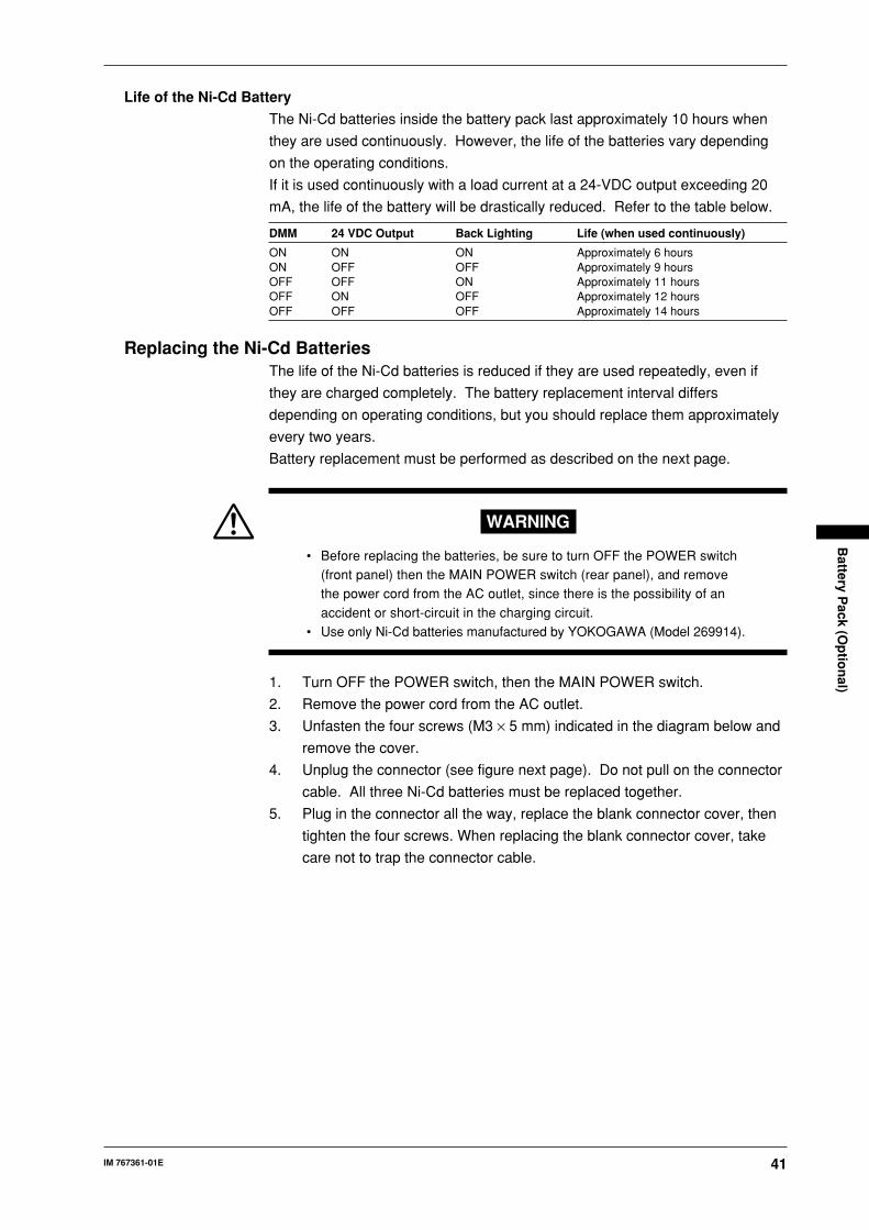
41IM 767361-01E
Battery P
ack (Op
tion
al)
Life of the Ni-Cd Battery
The Ni-Cd batteries inside the battery pack last approximately 10 hours when
they are used continuously. However, the life of the batteries vary depending
on the operating conditions.
If it is used continuously with a load current at a 24-VDC output exceeding 20
mA, the life of the battery will be drastically reduced. Refer to the table below.
DMM 24 VDC Output Back Lighting Life (when used continuously)
ON ON ON Approximately 6 hoursON OFF OFF Approximately 9 hoursOFF OFF ON Approximately 11 hoursOFF ON OFF Approximately 12 hoursOFF OFF OFF Approximately 14 hours
Replacing the Ni-Cd BatteriesThe life of the Ni-Cd batteries is reduced if they are used repeatedly, even if
they are charged completely. The battery replacement interval differs
depending on operating conditions, but you should replace them approximately
every two years.
Battery replacement must be performed as described on the next page.
WARNING
• Before replacing the batteries, be sure to turn OFF the POWER switch(front panel) then the MAIN POWER switch (rear panel), and removethe power cord from the AC outlet, since there is the possibility of an
accident or short-circuit in the charging circuit.• Use only Ni-Cd batteries manufactured by YOKOGAWA (Model 269914).
1. Turn OFF the POWER switch, then the MAIN POWER switch.
2. Remove the power cord from the AC outlet.
3. Unfasten the four screws (M3 × 5 mm) indicated in the diagram below and
remove the cover.
4. Unplug the connector (see figure next page). Do not pull on the connector
cable. All three Ni-Cd batteries must be replaced together.
5. Plug in the connector all the way, replace the blank connector cover, then
tighten the four screws. When replacing the blank connector cover, take
care not to trap the connector cable.
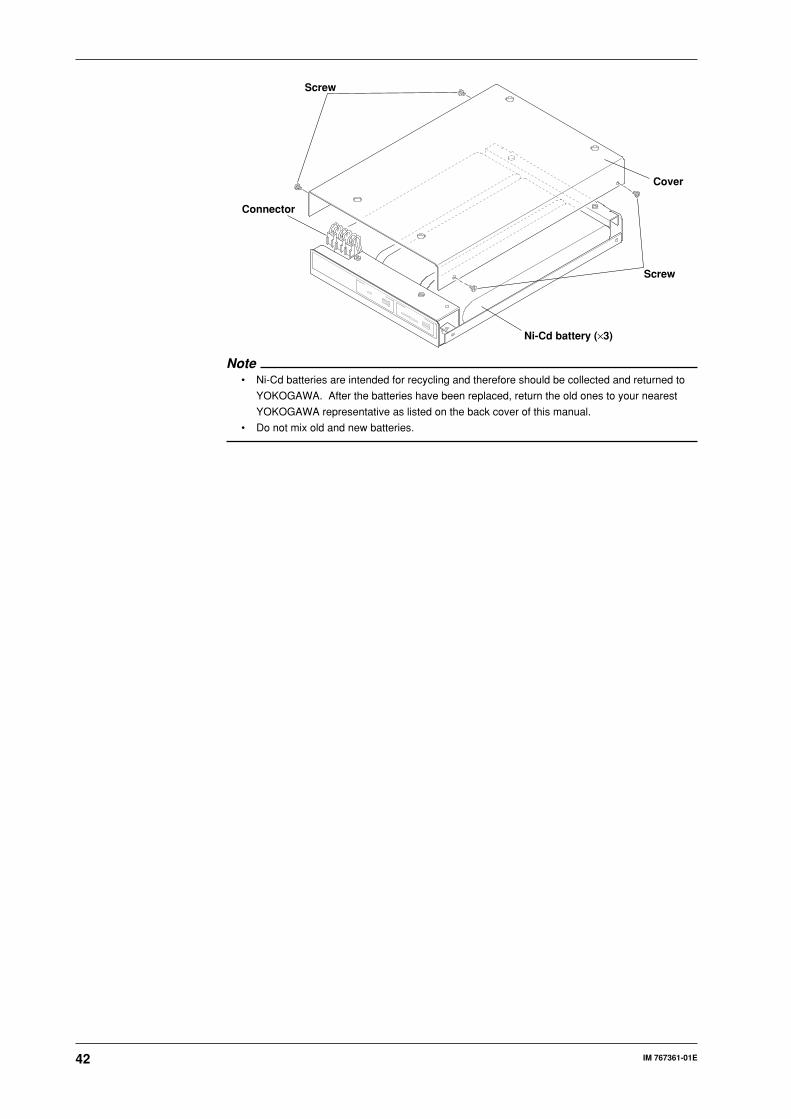
42 IM 767361-01E
Connector
Screw
Screw
Ni-Cd battery (×3)
Cover
Note• Ni-Cd batteries are intended for recycling and therefore should be collected and returned to
YOKOGAWA. After the batteries have been replaced, return the old ones to your nearest
YOKOGAWA representative as listed on the back cover of this manual.
• Do not mix old and new batteries.
43IM 767361-01E
Overview
of th
e GP
-IB In
terface
Overview of the GP-IB Interface
GP-IB Interface FunctionListener
It is possible to enter the same settings via the GP-IB interface that can be
made using the front panel keys.
Measured or computed data, panel setup information, and error codes can be
received.
Talker
Measured or computed data can be output.
Panel setup information and the status byte can be output.
Error codes which have occurred can be output.
GP-IB Interface SpecificationsElectrical and mechanical specifications : Conforms to IEEE St’d 488-1978.
Functional Specifications : See the table below.
Code : ISO (ASCII) code
Address setting : Listener and talker addresses 0 to 30,
or talk-only can be selected.
Remote mode clear : Remote mode can be cleared by
pressing the ENTER/LOCAL on the
front panel. However, this is not
possible if Local Lockout has been
set by the controller.
Functional Specifications
Function Subset Name Description
Source handshaking SH1 Full source handshaking capabilityAcceptor handshaking AH1 Full acceptor handshaking capabilityTalker T5 Basic talker capability, serial polling, untalk on MLA
(My Listen Address), talk-only capabilityListener L4 Basic listener capability, unlisten on MTA (My Talk
Address), no listen-only capabilityService request SR1 Full service request capabilityRemote local RL1 Full remote/local capabilityParallel poll PP0 No parallel polling capabilityDevice clear DC1 Full device clear capabilityDevice trigger DT1 Full device trigger capabilityController C0 No controller function
Turning GP-IB ON/OFFWhen starting up using DC power or the battery back, GP-IB is turned OFF.
Turn it ON before use.
44 IM 767361-01E
Interface Messages Supported by the Instrument• IFC (Interface Clear)
Cancels (unaddresses) talker and listener.
• REN (Remote Enable)
Transfers the instrument from local control to remote control.
• GTL (Go To Local)
Transfers the instrument from remote control to local control.
• SDC (Selective Device Clear), DCL (Device Clear)
Clears the GP-IB input/output buffer and resets after an error. The setup
information and measurement state are not affected.
DCL applies to all devices on the bus, while DSC applies only to designated
devices.
• GET (Group Execute Trigger)
Updates the displayed data during sample hold.
• LLO (Local Lockout)
Invalidates the ENTER/LOCAL on the front panel, preventing an inadvertent
switch from remote control to local control.
Switching between Remote and Local ModeREMOTE is displayed on the screen when the instrument is in remote mode.
No front panel keys except the ENTER/LOCAL can be operated.
To cancel remote mode, press the ENTER/LOCAL. REMOTE will disappear
from the screen, indicating that the instrument is now in local mode. However,
this is not possible if Local Lockout has been set.
Setting the Mode and AddressThe following operation modes are available for the GP-IB interface provided
with the instrument.
Setting the Mode
Addressable Mode
In this mode, the instrument is controlled by commands issued from the
controller. When the OD command (measured or computed data output
request command) is received, the instrument outputs the measured or
computed data.
Talk-Only Mode
This mode does not require a controller.
Measured or computed data is output at the display update intervals. This
mode is useful when the instrument is connected to a listener-only device such
as a printer.
Setting the Address
A particular address is assigned to each device connected to the GP-IB
interface so that every device can be recognized by every other device.
Therefore, an address must be assigned to this instrument when it is connected
to a personal computer.
If this instrument is to be used with a listen-only device, it must be set to talk-
only mode.
45IM 767361-01E
Overview
of th
e GP
-IB In
terface
Address Setting Range
0–30
The factory setting is 1.
Talk-Only Function
This function only allows the instrument to send measured or computed data to
other devices. Even if the instrument is not assigned as a talk-only device, it
can still send data. In talk-only mode, the instrument cannot be controlled by
the controller.
Setting the GP-IB Interface1. Press MENU.
Keep pressing or until is displayed in the lower part of the
screen, then press ENTER/LOCAL.
Proceed to step 2 when using the battery pack or DC power supply.
Proceed to step 3 when using the AC power supply.
2. Use the and to set the GP-IB function ( ) and press ENTER/
LOCAL.
: Activates the function.
: Deactivates the function.
3. Press or to select (addressable mode) or (talk-only
mode), then confirm the selection by pressing ENTER/LOCAL.
4. If addressable mode is selected, keep pressing until the desired digit
starts to blink, then set the desired value by pressing or to set the
address ( ), then press ENTER/LOCAL.
5. Press MENU to return to the normal measurement screen.
46 IM 767361-01E
Overview of the RS-232 Interface
RS-232 Interface FunctionsReceiving Function
It is possible to enter the same settings via the RS-232 interface as can be
entered using the front panel keys.
Measured or computed data, panel setup information, and error codes can be
received.
Sending Function
Measured or computed data can be output.
Panel setup information and the status byte can be output.
Error codes which have occurred can be output.
RS-232 Interface Specifications• Electrical characteristics : Complies with the EIA232(RS-232) standard
• Connection : Point-to-point
• Communications : Full-duplex
• Synchronization : Start-stop system
• Baud Rate : 1200, 2400, 4800, 9600
• Start bit : 1 bit
• Data length (word length) : 7 or 8 bits
• Parity : EVEN, ODD, or OFF (no parity)
• Stop bit : 1 or 2 bits
• Hardware handshaking : User can select whether CA and CB signals will
always be True, or will be used for control.
• Software handshaking : User can select whether to control only
transmission or both transmission and reception
using X-on and X-off signals.
X-on (ASCII 11H)
X-off (ASCII 13H)
• Receive buffer size : 256 bytes
Connecting the RS-232 Interface CableWhen connecting this instrument to a computer, make sure that the
handshaking method, data transmission rate, and data format selected for the
instrument match those selected for the computer.
For details, refer to the following pages. Also make sure that the correct
interface cable is used.
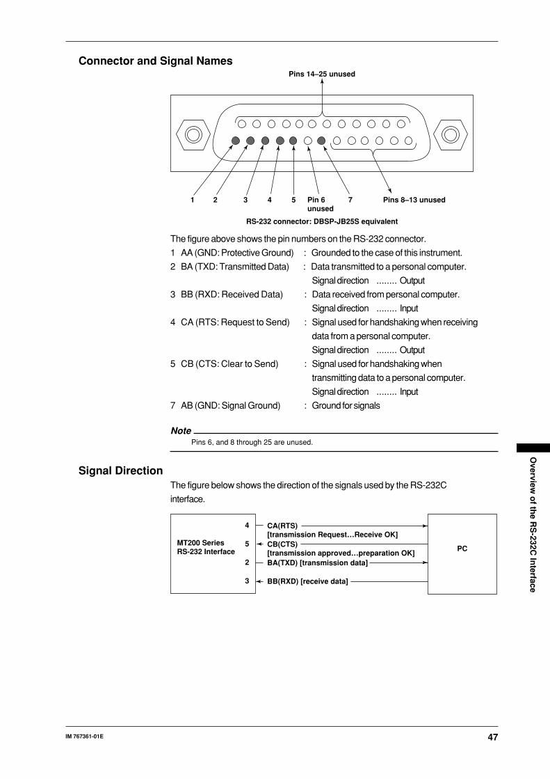
47IM 767361-01E
Overview
of th
e RS
-232C In
terface
Connector and Signal NamesPins 14–25 unused
Pins 8–13 unused1 2 3 4 5 Pin 6 unused
7
RS-232 connector: DBSP-JB25S equivalent
The figure above shows the pin numbers on the RS-232 connector.
1 AA (GND: Protective Ground) : Grounded to the case of this instrument.
2 BA (TXD: Transmitted Data) : Data transmitted to a personal computer.
Signal direction ........ Output
3 BB (RXD: Received Data) : Data received from personal computer.
Signal direction ........ Input
4 CA (RTS: Request to Send) : Signal used for handshaking when receiving
data from a personal computer.
Signal direction ........ Output
5 CB (CTS: Clear to Send) : Signal used for handshaking when
transmitting data to a personal computer.
Signal direction ........ Input
7 AB (GND: Signal Ground) : Ground for signals
NotePins 6, and 8 through 25 are unused.
Signal DirectionThe figure below shows the direction of the signals used by the RS-232C
interface.
CA(RTS) [transmission Request…Receive OK]CB(CTS) [transmission approved…preparation OK]BA(TXD) [transmission data]
BB(RXD) [receive data]
4
5
2
3
MT200 SeriesRS-232 Interface PC
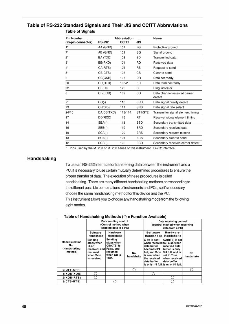
48 IM 767361-01E
Table of RS-232 Standard Signals and Their JIS and CCITT AbbreviationsTable of Signals
Pin Number Abbreviation Name(25-pin connector) RS-232 CCITT JIS
1* AA (GND) 101 FG Protective ground
7* AB (GND) 102 SG Signal ground
2* BA (TXD) 103 SD Transmitted data
3* BB(RXD) 104 RD Received data
4* CA(RTS) 105 RS Request to send
5* CB(CTS) 106 CS Clear to send
6 CC(CSR) 107 DR Data set ready
20 CD(DTR) 108/2 ER Data terminal ready
22 CE(RI) 125 CI Ring indicator
8 CF(DCD) 109 CD Data channel received carrierdetect
21 CG(-) 110 SRS Data signal quality detect
23 CH/CI(-) 111 SRS Data signal rate select
24/15 DA/DB(TXC) 113/114 ST1/ST2 Transmitter signal element timing
17 DD(RXC) 115 RT Receiver signal element timing
14 SBA(-) 118 BSD Secondary transmitted data
16 SBB(-) 119 BRD Secondary received data
19 SCA(-) 120 BRS Secondary request to send
13 SCB(-) 121 BCS Secondary clear to send
12 SCF(-) 122 BCD Secondary received carrier detect
* Pins used by the MT200 or MT200 series or this instrument RS-232 interface.
HandshakingTo use an RS-232 interface for transferring data between the instrument and a
PC, it is necessary to use certain mutually determined procedures to ensure the
proper transfer of data. The execution of these procedures is called
handshaking. There are many different handshaking methods corresponding to
the different possible combinations of instruments and PCs, so it’s necessary
choose the same handshaking method for this device and the PC.
This instrument allows you to choose any handshaking mode from the following
eight modes.
Data sending control (Control method when sending data to a PC)
Data receiving control (control method when receiving
data from a PC)
Software Handshake
Software Handshake
0(OFF-OFF)1(XON-XON)2(XON-RTS)3(CTS-RTS)
Mode Selection No.
(Handshaking method)
Sending stops when X-off received, and resumed when X-on is received.
Sending stops when CB(CTS) is False, and resumed when CB is True.
No handshake
No handshake
X-off is sent when received data buffer becomes 3/4 full, and X-on is sent when the received data buffer is only 1/4 full.
CA(RTS) is set to Falso when received data buffer is only 3/4 full, and is set to True when received data buffer is only 1/4 full.
Hardware Handshake
Hardware Handshake
Table of Handshaking Methods ( = Function Available)
49IM 767361-01E
Overview
of th
e RS
-232C In
terface
Description of Each Handshaking MethodOFF-OFF
• Data Sending Control
Handshaking is not carried out between the instrument and the PC. X-on
and X-off messages from the PC are treated as data, and CB(CTS) is
ignored.
• Data Receiving Control
Handshaking is not carried out between the instrument and the PC. After the
instrument’s receive buffer becomes FULL, excess data is discarded.
Therefore, in order to prevent both the instrument’s and the PC's receive
buffers from becoming FULL, you should create a program on the PC.
CA(RTS) is fixed at True.
XON-XON
• Data Sending Control
Software handshaking is carried out between the instrument and the PC. If
the instrument receives the X-off code from the PC while the instrument is
transmitting data, the transmission is stopped until the X-on code is received.
CB(CTS) messages from the PC are ignored.
• Data Receiving Control
Software handshaking is carried out between the instrument and the PC.
When the instrument’s available buffer space reaches 64 bytes it transmits
an X-off code to the PC, and when the buffer space reaches 192 bytes an X-
on code is sent. CA(RTS) is fixed at True.
XON-RTS
• Data Sending Control
Software handshaking is carried out between the instrument and the PC. If
the instrument receives the X-off code from the PC while the instrument is
transmitting data, the transmission is stopped until the X-on code is received.
CB(CTS) messages from the PC are ignored.
• Data receiving control
Hardware handshaking is carried out between the instrument and the PC.
When the instrument’s receive buffer reaches 64 bytes CA(RTS) is set to
False, and when the buffer reaches 192 bytes CA(RTS) is set to True.
CTS-RTS
• Data Sending Control
Hardware handshaking is carried out between the instrument and the PC. If
CB(CTS) becomes False while the instrument is transmitting data, the
transmission is stopped until CB(CTS) becomes True again. X-on and X-off
messages from the PC are treated as data.
• Data Receiving Control
Hardware handshaking is carried out between the instrument and the PC.
When the instrument’s receive buffer reaches 64 bytes, CA(RTS) is set to
False, and when the buffer reaches 192 bytes CA(RTS) is set to True.
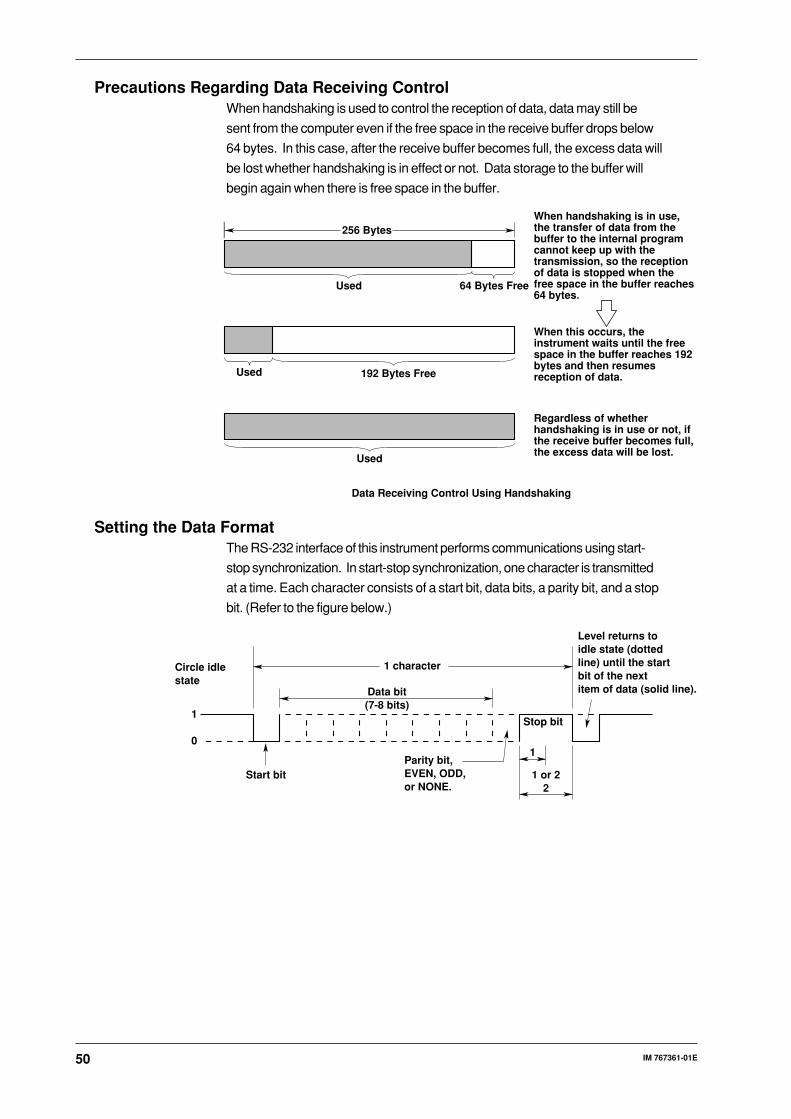
50 IM 767361-01E
Precautions Regarding Data Receiving ControlWhen handshaking is used to control the reception of data, data may still be
sent from the computer even if the free space in the receive buffer drops below
64 bytes. In this case, after the receive buffer becomes full, the excess data will
be lost whether handshaking is in effect or not. Data storage to the buffer will
begin again when there is free space in the buffer.
256 Bytes
Used 64 Bytes Free
When handshaking is in use, the transfer of data from the buffer to the internal program cannot keep up with the transmission, so the reception of data is stopped when the free space in the buffer reaches 64 bytes.
Used 192 Bytes Free
When this occurs, the instrument waits until the free space in the buffer reaches 192 bytes and then resumes reception of data.
Used
Regardless of whether handshaking is in use or not, if the receive buffer becomes full, the excess data will be lost.
Data Receiving Control Using Handshaking
Setting the Data FormatThe RS-232 interface of this instrument performs communications using start-
stop synchronization. In start-stop synchronization, one character is transmitted
at a time. Each character consists of a start bit, data bits, a parity bit, and a stop
bit. (Refer to the figure below.)
Data bit(7-8 bits)
1 character
Stop bit
1
1 or 22
Parity bit, EVEN, ODD, or NONE.
Start bit
Circle idle state
Level returns to idle state (dotted line) until the start bit of the next item of data (solid line).
1
0
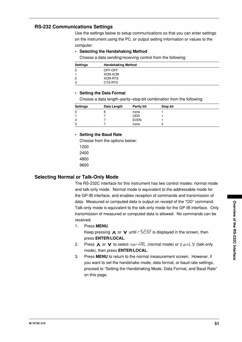
51IM 767361-01E
Overview
of th
e RS
-232C In
terface
RS-232 Communications SettingsUse the settings below to setup communications so that you can enter settings
on the instrument using the PC, or output setting information or values to the
computer.
• Selecting the Handshaking Method
Choose a data sending/receiving control from the following:
Settings Handshaking Method
0 OFF-OFF1 XON-XON2 XON-RTS3 CTS-RTS
• Setting the Data Format
Choose a data length–parity–stop-bit combination from the following:
Settings Data Length Parity bit Stop bit
0 8 none 11 7 ODD 12 7 EVEN 13 7 none 2
• Setting the Baud Rate
Choose from the options below:
1200
2400
4800
9600
Selecting Normal or Talk-Only ModeThe RS-232C interface for this instrument has two control modes: normal mode
and talk-only mode. Normal mode is equivalent to the addressable mode for
the GP-IB interface, and enables reception of commands and transmission of
data. Measured or computed data is output on receipt of the “OD” command.
Talk-only mode is equivalent to the talk-only mode for the GP-IB interface. Only
transmission of measured or computed data is allowed. No commands can be
received.
1. Press MENU.
Keep pressing or until is displayed in the screen, then
press ENTER/LOCAL.
2. Press or to select (normal mode) or (talk-only
mode), then press ENTER/LOCAL.
3. Press MENU to return to the normal measurement screen. However, if
you want to set the handshake mode, data format, or baud rate settings,
proceed to “Setting the Handshaking Mode, Data Format, and Baud Rate”
on this page.
52 IM 767361-01E
Setting the Handshaking Mode, Data Format, and Baud Rate4. With the handshake mode setting screen ( ) displayed, press or
to set the value corresponding to the desired mode, then press
ENTER/LOCAL. For a description of the settings, refer to the table given
on the previous page.
5. With the data format setting screen ( ) displayed, press or to
set the value corresponding to the desired data format, then press ENTER/
LOCAL. For a description of the settings, refer to the table given on the
previous page.
6. With the data format setting screen ( ) displayed, press or to
set the value corresponding to the desired data format, then press ENTER/
LOCAL.
RS-232 Specific CommandsThe following commands imitate the interface message function of the GP-IB
interface.
<ESC>S <Terminator>
Equivalent to the GP-IB’s serial poll function. The status byte is output when
this command is received.
<ESC>R <Terminator>
Equivalent to the GP-IB’s remote/local control function. The instrument is
placed in remote status and the panel keys become inoperative when this
command is received. Press the ENTER/LOCAL to exit from remote status.
<ESC>L <Terminator>
Equivalent to the GP-IB’s remote/local control function. When this instrument is
in remote status, the instrument will be placed in local status when this
command is received.
<ESC>C <Terminator>
Equivalent to the GP-IB’s device clear function. The instrument’s
communications interface is initialized when this command is received.
53IM 767361-01E
Befo
re Pro
gram
min
g
Before Programming
Basic Programming FormatThe following shows the structure of program data.
Command + Parameter + Terminator
ASCII codes are used.
Example DF 2 CRLF
Command Parameter Terminator
Command
Predefined string of 1 to 3 capital letters
Parameter
Numeric values or character string (ASCII code)
Terminator
GP-IB interface
Specify CR+LF, LF, or EOI for the receive terminator.
The “DL” command is used to set the transmit terminator. The default setting
is CR+LF+EOI. For details, see page App-5.
RS-232 Communications Settings
Specify CR+LF or EOI for the receive terminator.
The “DL” command is used to set the transmit terminator. The default setting
is CR+LF.
For details, see page App-5.
Precautions when ProgrammingA single line can contain multiple commands. In this case, make sure that
command statements (a command + parameters) are separated by a semicolon
(;).
NoteA space or tab between the command and parameter can be omitted.
How to Use the AppendixQuery Command
Query commands can easily be identified since a question mark (?) is added to
the end of the command. Data returned in response to a query command is
shown as in the example below.
Query Returned data
HD? → HD1
Sample Program
Sample programs demonstrating the commands are given in the appendix.
Refer to page App-16.
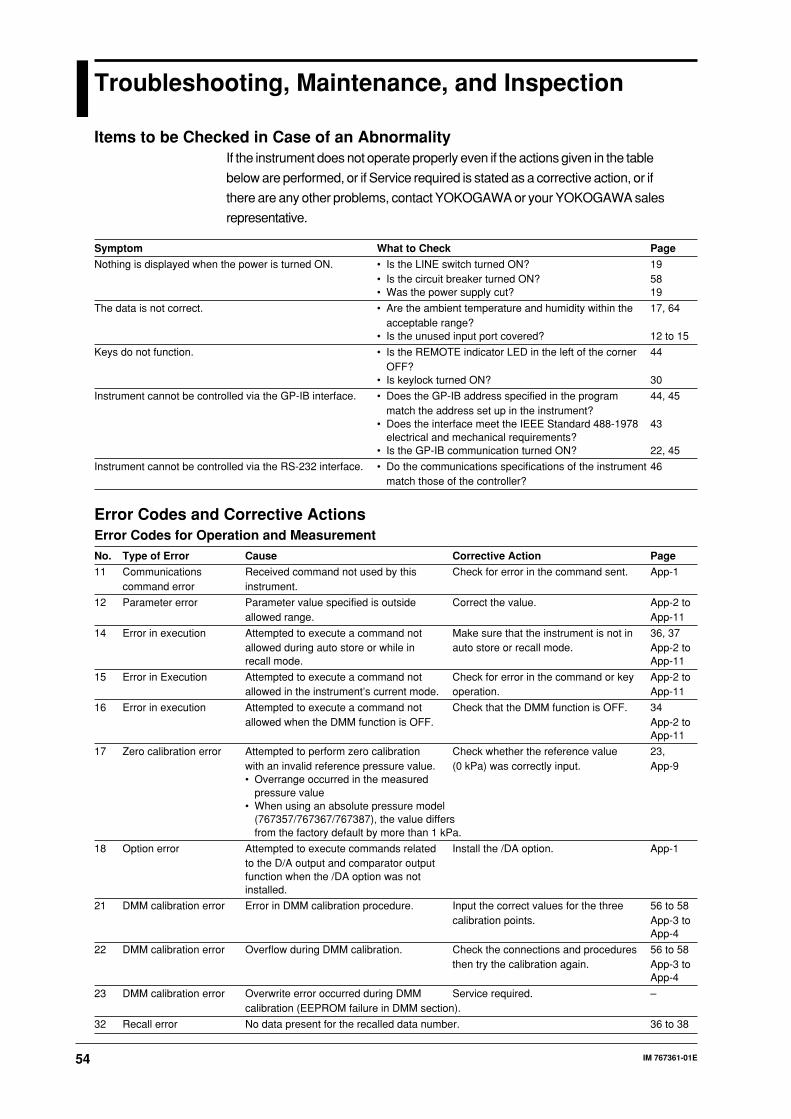
54 IM 767361-01E
Troubleshooting, Maintenance, and Inspection
Items to be Checked in Case of an AbnormalityIf the instrument does not operate properly even if the actions given in the table
below are performed, or if Service required is stated as a corrective action, or if
there are any other problems, contact YOKOGAWA or your YOKOGAWA sales
representative.
Symptom What to Check Page
Nothing is displayed when the power is turned ON. • Is the LINE switch turned ON? 19• Is the circuit breaker turned ON? 58• Was the power supply cut? 19
The data is not correct. • Are the ambient temperature and humidity within the 17, 64acceptable range?
• Is the unused input port covered? 12 to 15
Keys do not function. • Is the REMOTE indicator LED in the left of the corner 44OFF?
• Is keylock turned ON? 30
Instrument cannot be controlled via the GP-IB interface. • Does the GP-IB address specified in the program 44, 45match the address set up in the instrument?
• Does the interface meet the IEEE Standard 488-1978 43electrical and mechanical requirements?
• Is the GP-IB communication turned ON? 22, 45
Instrument cannot be controlled via the RS-232 interface. • Do the communications specifications of the instrument 46match those of the controller?
Error Codes and Corrective ActionsError Codes for Operation and Measurement
No. Type of Error Cause Corrective Action Page
11 Communications Received command not used by this Check for error in the command sent. App-1command error instrument.
12 Parameter error Parameter value specified is outside Correct the value. App-2 toallowed range. App-11
14 Error in execution Attempted to execute a command not Make sure that the instrument is not in 36, 37allowed during auto store or while in auto store or recall mode. App-2 torecall mode. App-11
15 Error in Execution Attempted to execute a command not Check for error in the command or key App-2 toallowed in the instrument’s current mode. operation. App-11
16 Error in execution Attempted to execute a command not Check that the DMM function is OFF. 34allowed when the DMM function is OFF. App-2 to
App-11
17 Zero calibration error Attempted to perform zero calibration Check whether the reference value 23,with an invalid reference pressure value. (0 kPa) was correctly input. App-9• Overrange occurred in the measured
pressure value• When using an absolute pressure model
(767357/767367/767387), the value differsfrom the factory default by more than 1 kPa.
18 Option error Attempted to execute commands related Install the /DA option. App-1to the D/A output and comparator outputfunction when the /DA option was notinstalled.
21 DMM calibration error Error in DMM calibration procedure. Input the correct values for the three 56 to 58calibration points. App-3 to
App-4
22 DMM calibration error Overflow during DMM calibration. Check the connections and procedures 56 to 58then try the calibration again. App-3 to
App-4
23 DMM calibration error Overwrite error occurred during DMM Service required. –calibration (EEPROM failure in DMM section).
32 Recall error No data present for the recalled data number. 36 to 38
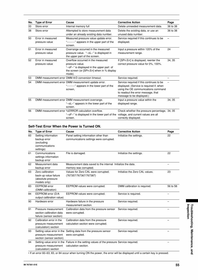
55IM 767361-01E
Tro
ub
lesho
otin
g, M
ainten
ance, an
dIn
spectio
n
No. Type of Error Cause Corrective Action Page
33 Store error Internal memory full Delete unneeded measurement data. 36 to 38
38 Store error Attempted to store measurement data Delete the existing data, or use an 36 to 38under an already existing data number. unused data number.
50 Error in measured Measured pressure value update error. Service required if this continues to be –pressure value “---------” appears in the upper part of the displayed.
screen.
51 Error in measured Overrange occurred in the measured Input a pressure within 120% of the 24pressure value pressure value. “--oL--” is displayed in measurement range.
the upper part of the screen.
52 Error in measured Overflow occurred in the measured If [SPn.Err] is displayed, reenter the 34, 35pressure value pressure value. correct pressure value for 0%, 100%.
“--oF--” is displayed in the upper part ofthe screen (or [SPn.Err] when in % displaymode).
53 DMM measurement error DMM A/D conversion timeout. Service required. –
54 DMM measurement error DMM measurement update error. Service required if this continues to be –“---------” appears in the lower part of the displayed. (Service is required if, whenscreen, using the OE communications command
to readout the error message, thatmessage to be displayed.)
55 DMM measurement error DMM measurement overrange. Input a pressure value within the 34, 35“--oL--” appears in the lower part of the displayed range.screen.
56 DMM measurement error %ERROR calculation overflow. Check whether the pressure percentage, 34, 35“--oF--” is displayed in the lower part of the voltage, and current values are allscreen. correctly displayed.
Self-Test Error When the Power is Turned ON.
No. Type of Error Cause Corrective Action Page
60 Setting information Panel setting information other than Initialize the settings. 22backup error communications settings were corrupted.(excludingcommunicationssettings)
61 Communications File is damaged. Initialize the settings. 22settings informationbackup error
62 Measurement data Measurement data saved to the internal Initialize the data. –backup error memory was corrupted.
63 Zero calibration Values for Zero CAL were corrupted. Initialize the Zero CAL values. 23back-up value failure (767357/767367/767387)(absolute pressuremodels only)
83 EEPROM error EEPROM values were corrupted. DMM calibration is required. 56 to 58(DMM calibration)
84 EEPROM error (D/A EEPROM values were corrupted. Service is required. –output calibration value)
90 Hardware error Hardware failure in the pressure Service required. –measurement section.
91 Pressure measurement Calibration data from the pressure sensor Service required. –section calibration data were corrupted.failure (sensor section)
92 Calibration error in the Calibration data from the pressure Service required. –pressure measurement calculation section were corrupted.(calculation) section
93 Setting value error in the Setting data from the pressure sensor Service required. –pressure measurement were corrupted.section (sensor section)
94 Setting value error in the Failure in the setting values of the pressure Service required. –pressure measurement calculation section.(calculation) section
• If an error 60–63, 83, or 84 occur when turning ON the power, the error will be displayed until a certain key is pressed.

56 IM 767361-01E
Calibrating the Pressure Measurement FunctionCalibration in this section means to establish the relationship between the
values displayed on the instrument and those shown on the standard
equipment.
It is recommended that the instrument be calibrated every six months since it is
a high accuracy measuring instrument. When calibrating, close attention should
be paid to the pressure standard used and the measurement environment.
The pressure standard used for calibration of this instrument must provide
tracability to the national standard and have an accuracy of ±0.01% or higher.
If a piston pressure gauge is used as the standard, apply the correct pressure to
calibrate the instrument, with the following taken into account: gravity at the
measuring point, weight of the piston, correction to be made due to buoyancy in
the air, temperature coefficient, and measuring temperature.
Calibration and adjustment of the accuracy can be performed at YOKOGAWA.
Calibration and adjustment of the accuracy requires a high level of skill, so
contact your nearest YOKOGAWA representative as listed on the back cover of
this manual.
Calibrating the DMM Function (MT220 Only)Calibration in this section means an adjustment of accuracy based on the
relationship between the values shown on the measuring instrument and those
shown on the standards instrument. Please note that it is up to the user to
calibrate the DMM function as YOKOGAWA does not perform this service.
Pressure Standards for Calibration
Digital multimeter: DC voltage measuring accuracy ±6 ppm,
(YOKOGAWA model 1281 recommended)
Standard resistor (100 Ω): Accuracy ±0.02%, (YOKOGAWA model 2794
recommended)
DC voltage/current generator: Stability ±0.02%, (YOKOGAWA model 7651
recommended)
EnvironmentAmbient temperature: 23±1°C
Corresponding humidity: 45 to 75%
Power supply voltage: 100 to 200/200 to 240 VAC, however you must use
the power cord supplied by YOKOGAWA with a 3-to-2
prong adapter, and connect it to an outlet with a
protective ground terminal.Frequency: 50±1 or 60±1 Hz
Vibration: An amount that will have only negligible effect on the
instrument
Electric/magnetic fields: A distance from such fields so that they will not effect
the measured values
Surrounding area: Amounts of gas from decomposing food, steam, salts,and dust that will not effect the measured values.
Warm-up: Before calibration, this instrument must be warmed up
for more than 30 minutes and earch standards
instrument must be warmed up for a time no shorter
than indicated by their specifications.

57IM 767361-01E
Tro
ub
lesho
otin
g, M
ainten
ance, an
dIn
spectio
n
Connection Method
Connect each instrument as shown below.
MT220
V Hi
Lo
DC voltage current
generator
Hi
Lo
Digital
multi-meter
MT220
Hi
Lo
Lo
Hi
Digital
multi-meter
COM2794
For voltage calibration For current calibration
COM
* Do not make any connections to the current terminal of the MT220.
* Do not make any connections to the voltage terminal of the MT220.
A DC voltage current
generator
Calibration Method
When you connect the pressure standard to each calibration point xi as shown
below, the value displayed on the instrument is given as yi since this is prior to
calibration. During the calibration, the correction factor is computed such that
xi=yi.Display
(x0, y0)
(x1, y1)
Input0
(x2, y2)(xi, yi) i=0, 1, 2 Calibration points
after calibrationbefor calibration
Procedure (Using the Front Panel Keys)
1. Press MENU.
2. Hold down the ZERO CAL button for 2 seconds, until the screen
appears. If this operation fails, is displayed. If this happens,
repeat the above operation.
3. In the screen, press or to display , then press ENTER/
LOCAL to enter calibration mode. Select to return to the normal
measurement screen.
4. Press or to select the calibration item (current or voltage), then
press ENTER/LOCAL. With this operation, the DMM measurement item
changes automatically.
5. Press or to select the calibration point, then press ENTER/LOCAL.
Set the calibration point in the order , , .
6. When all three calibration points have been set, set the output on the
standard instrument. Read the values from the output of the standard
equipment on the digital multimeter, then press or to enter those
values as calibration points. Then press ENTER/LOCAL. That is, for a
calibration point of 0, you must enter 0 on the instrument (if the standards
instrument cannot output a 0, short the voltage input terminal during voltage
calibration and open the current input terminal during current calibration.)
7. The measured value prior to calibration is displayed for one second. If the
values set as calibration points differ greatly from the measured values
there may have been a user error or a problem with the connections, so
enter the same calibration points once again.
selected +FS
DC generator set to 5V
read value of DMM
measured value befor calibration
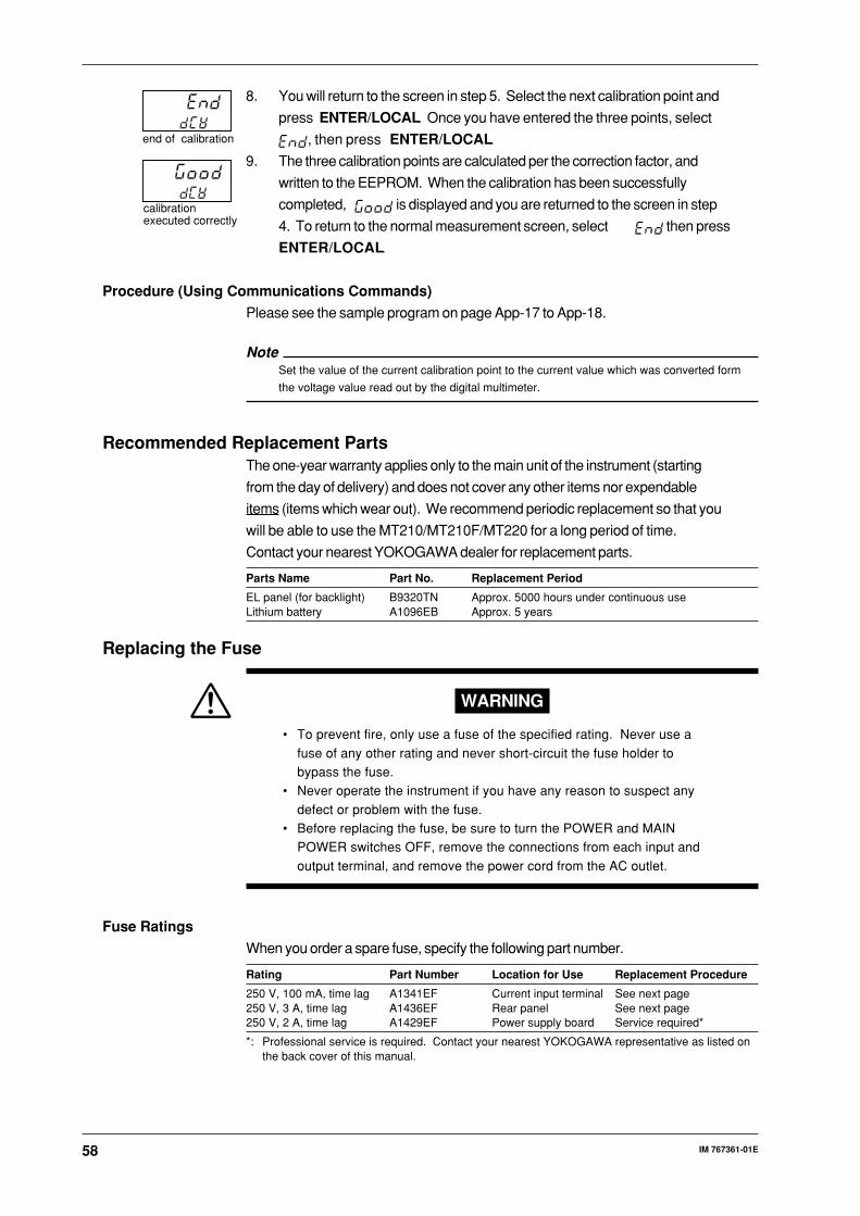
58 IM 767361-01E
8. You will return to the screen in step 5. Select the next calibration point and
press ENTER/LOCAL. Once you have entered the three points, select
, then press ENTER/LOCAL.
9. The three calibration points are calculated per the correction factor, and
written to the EEPROM. When the calibration has been successfully
completed, is displayed and you are returned to the screen in step
4. To return to the normal measurement screen, select then press
ENTER/LOCAL.
Procedure (Using Communications Commands)
Please see the sample program on page App-17 to App-18.
NoteSet the value of the current calibration point to the current value which was converted form
the voltage value read out by the digital multimeter.
Recommended Replacement PartsThe one-year warranty applies only to the main unit of the instrument (starting
from the day of delivery) and does not cover any other items nor expendable
items (items which wear out). We recommend periodic replacement so that you
will be able to use the MT210/MT210F/MT220 for a long period of time.
Contact your nearest YOKOGAWA dealer for replacement parts.
Parts Name Part No. Replacement Period
EL panel (for backlight) B9320TN Approx. 5000 hours under continuous useLithium battery A1096EB Approx. 5 years
Replacing the Fuse
WARNING
• To prevent fire, only use a fuse of the specified rating. Never use a
fuse of any other rating and never short-circuit the fuse holder tobypass the fuse.
• Never operate the instrument if you have any reason to suspect any
defect or problem with the fuse.• Before replacing the fuse, be sure to turn the POWER and MAIN
POWER switches OFF, remove the connections from each input and
output terminal, and remove the power cord from the AC outlet.
Fuse Ratings
When you order a spare fuse, specify the following part number.
Rating Part Number Location for Use Replacement Procedure
250 V, 100 mA, time lag A1341EF Current input terminal See next page250 V, 3 A, time lag A1436EF Rear panel See next page250 V, 2 A, time lag A1429EF Power supply board Service required*
*: Professional service is required. Contact your nearest YOKOGAWA representative as listed onthe back cover of this manual.
end of calibration
calibration executed correctly

59IM 767361-01E
Tro
ub
lesho
otin
g, M
ainten
ance, an
dIn
spectio
n
Fuse Position and Replacement Method
Turn the fuse holder to the left and pull out the fuse holder. Then, replace with
a new fuse.
Turn the fuse holder to the left and pull out the
fuse holder. Then, replace with a new fuse.
Each current input terminal accommodates a built-in fuse. A fuse is contained
in the fuse holder as shown below. To replace the fuse, turn the fuse holder
counter-clockwise with your fingers to remove it, then replace the fuse with a
new one.

60 IM 767361-01E
Specifications
Pressure Measurement Section (767351/767361/767381/767353/767363/767383/767355/767365/767385)Model Code 767351/767361/767381 767353/767363/767383 767355/767365/767385
Pressure Type Gauge pressure Gauge pressure Gauge pressure
Measuring Range Positive pressure: 0 to 10 kPa Positive pressure: 0 to 130 kPa Positive pressure: 0 to 700 kPa(Accuracy guaranteed) Negative pressure: –10 to 0 kPa Negative pressure: –80 to 0 kPa Negative pressure: –80 to 0 kPa
Maximum Display –12.0000 to 12.0000 kPa to 156.000 kPa to 840.00 kPa
Accuracy*1 Positive pressure Positive pressure 20 to 130 kPa: Positive pressure:(Zero CAL) ±(0.01% of rdg +0.15% of FS) ±(0.01% of rdg +3 digits) ±(0.01% of rdg +0.005% of FS)6 months after calibration 0 to 20 kPa: ±5 digitsNormal measurement Negative pressure Negative pressure Negative pressuremode ±(0.2% of rdg +0.1% of FS) ±(0.2% of rdg +0.1% of FS) ±(0.2% of rdg +0.1% of FS)(Averaging ON)
Medium-speed*2 ±0.02% of FS ±0.02% of FS ±0.02% of FSmeasurement mode(added to normalmeasurement mode)
High-speed mode*2 ±0.04% of FS ±0.03% of FS ±0.03% of FS(added to medium-speedmeasurement mode)
One year after calibration ±0.01% of FS ±0.005% of FS ±0.005% of FS(Represented by addingthe value shown on theright to the accuracypercentages given above forsix months after calibration.)
Display Update Interval*3
Normal measurement 250 ms 250 ms 250 msmode
Medium-speed*2 100 ms 100 ms 100 msmeasurement mode
High-speed*2 100 ms 100 ms 100 msmeasurement mode
Response Time*4
Normal measurement 2.5 s or lower 2.5 s or lower 2.5 s or lowermode
Medium-speed*2 200 ms or lower 200 ms or lower 200 ms or lowermeasurement mode
High-speed*2 200 ms or lower 50 ms or lower 70 ms or lowermeasurement mode
Resolution 0.0001 kPa 0.001 kPa 0.01 kPa
Internal Capacity Approx. 10 cm3 Approx. 10 cm3 Approx. 10 cm3
Input Tolerance 2.7 kPa abs to 500 kPa gauge 2.7 kPa abs to 500 kPa gauge 2.7 kPa abs to 3000 kPa gauge(Up to 50 kPa gauge for the 767381)
Temperature Coefficient Zero drift ±0.0015% of FS/°C Zero drift ±0.001% of FS/°C Zero drift ±0.001% of FS/°CSensitivity ±0.001% of FS/°C Sensitivity ±0.001% of FS/°C Sensitivity ±0.001% of FS/°C
Effect of Inclination at 90° inclined forward or at 90° inclined forward or at 90° inclined forward orbackward backward backwardZero drift ±0.1% of F.S. Zero drift ±0.01% of FS Zero drift ±0.01% of FS30° inclined right or left 30° inclined right or left 30° inclined right or leftZero point ±2.5% of FS Zero point ±0.2% of FS Zero point ±0.05% of FS
Weight (Main unit) 767351: approx. 8 kg 767353: approx. 7 kg 767385: approx. 6.5 kg767361/767381: approx. 8 kg 767363/767383: approx. 6.5 kg 767355: approx. 8.5 kg/
767365: approx. 8 kg
*1 Operating conditions: Temperature 23 ± 3°C, humidity 20 to 80% RH, power voltage rating ±5%, positioned horizontally.Refer to Yokogawa’s pressure standard.
*2 Measurement mode can be switched between normal, medium-speed, and high-speed on the 76738 only.*3 Data output rate via communications is the same as the display update rate.*4 Measurement conditions of response time:
• Time from the start of change until the value settles within ±1% of the convergence value.• Release from full scale value to atmospheric pressure. (Input section is no load condition. From 0 to atmospheric pressure
for the absolute pressure model.)• Measure using D/A output.

61IM 767361-01E
Sp
ecification
s
Pressure Measurement Section (767356/767366/767386/767357/767367/767387)Model Code 767356/767366/767386 767357/767367/767387
Pressure Type Gauge pressure Absolute pressure
Measuring Range Positive pressure: 0 to 3000 kPa 0 to 130 kPa abs(Accuracy guaranteed) Negative pressure: –80 to 0 kPa
Maximum Display to 3600.00 kPa to 156.000 kPa abs
Accuracy*1 Positive pressure ±(0.01% of rdg +0.005% of FS)(Zero CAL) ±(0.01% of rdg +0.005% of FS)6 months after calibrationNormal measurement Negative pressuremode ±(0.2% of rdg +0.1% of FS)(Averaging ON)
Medium-speed*2 ±0.02% of FS ±0.02% of FSmeasurement mode(added to normalmeasurement mode)
High-speed mode*2 ±0.03% of FS ±0.03% of FS(added to medium-speedmeasurement mode)
One year after calibration ±0.005% of FS ±0.005% of FS(Represented by addingthe value shown right tothe accuracy percentagesgiven for six months aftercalibration.)
Display update interval*3
Normal measurement 250 ms 250 msmode
Medium-speed*2 100 ms 100 msmeasurement mode
High-speed*2 100 ms 100 msmeasurement mode
Response Time*4
Normal measurement 2.5 s or lower 2.5 s or lowermode
Medium-speed*2 200 ms or lower 200 ms or lowermeasurement mode
High-speed*2 100 ms or lower 50 ms or lowermeasurement mode
Resolution 0.01 kPa 0.001 kPa
Input Tolerance 2.7 kPa abs to 4500 kPa gauge 1 Pa abs to 500 kPa gauge
Internal Capacity Approx. 10 cm3 Approx. 10 cm3
Temperature Coefficient Zero drift ±0.001% of FS/°C Zero drift ±0.001% of FS/°CSensitivity ±0.001% of FS/°C Sensitivity ±0.001% of FS/°C
Effect of Inclination at 90° inclined forward or backward at 90° inclined forward or backwardZero point ±0.01% of FS Zero point ±0.01% of FS30° inclined right or left 30° inclined right or leftZero point ±0.01% of FS Zero point ±0.2% of FS
Weight (Main unit) 767356: approx. 7 kg 767357: approx. 7 kg767366/767386: approx. 6.5 kg 767367/767387: approx. 6.5 kg
*1 Operating conditions: Temperature 23 ± 3°C, humidity 20 to 80% RH, power voltage rating ±5%, positioned horizontally.Refer to Yokogawa’s pressure standard.
*2 Measurement mode can be switched between normal, medium-speed, and high-speed on the 76738 only.*3 Data output rate via communications is the same as the display update rate.*4 Measurement conditions of response time:
• Time from the start of change until the value settles within ±1% of the convergence value.• Release from full scale value to atmospheric pressure. (Input section is no load condition. From 0 to atmospheric pressure
for the absolute pressure model.)• Measure using D/A output.

62 IM 767361-01E
Pressure Measurement Section (767370/767371)Model Code 767370 767371
Pressure Type Differential pressure (H input ≥ L input) Differential pressure (H input ≥ L input)
Measuring Range 0 to 1 kPa 0 to 10 kPa(Accuracy guaranteed)
Maximum Display –1.20000 to 1.20000 kPa –12.0000 to 12.0000 kPa
Accuracy*1 ±(0.015% of rdg +0.03% of FS) ±(0.01% of rdg +0.025% of FS)(Zero CAL)6 months after calibration
One year after calibration ±0.01% of FS ±0.01% of FS(Represented by addingthe value shown right tothe accuracy percentagesgiven for six months aftercalibration.)
Display update interval 250 ms 250 ms
Response time 5 s or less 2.5 s or less
Resolution 0.00001 kPa 0.0001 kPa
Input Tolerance 1 Pa abs to 50 kPa gauge*2 2.7 kPa abs to 500 kPa gauge
Internal Capacity L and H, approx. 10cm3 L and H, approx. 10cm3
Temperature Coefficient Zero drift ±0.005% of FS/°C Zero drift ±0.0015% of FS/°CSensitivity ±0.001% of FS/°C Sensitivity ±0.001% of FS/°C
Effect of Inclination at 90° inclined forward or backward at 90° inclined forward or backwardZero point ±0.5% of FS Zero point ±0.1% of FS5° inclined right or left 30° inclined right or leftZero point ±3% of FS Zero point ±2.5% of FS
Weight (Main unit) Approx. 8.2 kg. Approx. 289 oz. Approx. 8.2 kg. Approx. 289 oz.
*1 Operating conditions: Temperature 23 ± 3°C, humidity 20 to 80% RH, power voltage rating ±5%, positioned horizontally.Averaging is OFF for the 767370 and ON for the 767371.
Refer to Yokogawa’s pressure standard.*2 The difference between L and H is less than 50 kPa
Pressure Measurement Section (767372/767373)Model Code 767372 767373
Pressure Type Differential pressure (H input ≥ L input) Differential pressure (H input ≥ L input)
Measuring Range 0 to 130 kPa 0 to 700 kPa(Accuracy guaranteed)
Maximum Display –156.000 to 156.000 kPa –156.00 to 840.00 kPa
Accuracy*1 20 to 130 kPa: ±(0.01% of rdg ±(0.01% of rdg +0.015% of FS)(Zero CAL) +(0.01% of FS + 3 digits)6 months after calibration(Averaging ON) 0 to 20 kPa: ±(0.01% of FS + 5 digits)
One year after calibration ±0.005% of FS ±0.005% of FS(Represented by addingthe value shown right tothe accuracy percentagesgiven for six months aftercalibration.)
Display update interval 250 ms 250 ms
Response time 2.5 s or less 2.5 s or less
Resolution 0.001 kPa 0.01 kPa
Input Tolerance 2.7 kPa abs to 500 kPa gauge 2.7 kPa abs to 1000 kPa gauge
Internal Capacity L and H, approx. 10cm3 L and H, approx. 10cm3
Temperature Coefficient Zero drift ±0.001% of FS/°C Zero drift ±0.001% of FS/°CSensitivity ±0.001% of FS/°C Sensitivity ±0.001% of FS/°C
Effect of Inclination*1 at 90° inclined forward or backward at 90° inclined forward or backwardZero point ±0.01% of FS Zero point ±0.01% of FS30° inclined right or left 30° inclined right or leftZero point ±0.2% of FS Zero point ±0.05% of FS
Weight (Main unit) Approx. 8.2 kg. Approx. 289 oz. Approx. 8.2 kg. Approx. 289 oz.
*1 Operating conditions: Temperature 23 ± 3°C, humidity 20 to 80% RH, power voltage rating ±5%, positioned horizontally.Refer to Yokogawa’s pressure standard.
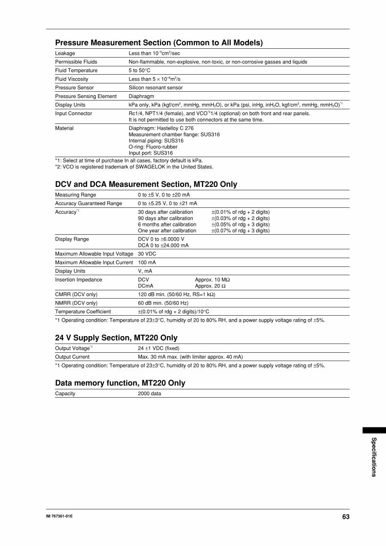
63IM 767361-01E
Sp
ecification
s
Pressure Measurement Section (Common to All Models)Leakage Less than 10–5cm3/sec
Permissible Fluids Non-flammable, non-explosive, non-toxic, or non-corrosive gasses and liquids
Fluid Temperature 5 to 50°C
Fluid Viscosity Less than 5 × 10⁻⁶m2/s
Pressure Sensor Silicon resonant sensor
Pressure Sensing Element Diaphragm
Display Units kPa only, kPa (kgf/cm2, mmHg, mmH2O), or kPa (psi, inHg, inH2O, kgf/cm2, mmHg, mmH2O)*1
Input Connector Rc1/4, NPT1/4 (female), and VCO*21/4 (optional) on both front and rear panels.It is not permitted to use both connectors at the same time.
Material Diaphragm: Hastelloy C 276Measurement chamber flange: SUS316Internal piping: SUS316O-ring: Fluoro-rubberInput port: SUS316
*1: Select at time of purchase In all cases, factory default is kPa.*2: VCO is registered trademark of SWAGELOK in the United States.
DCV and DCA Measurement Section, MT220 OnlyMeasuring Range 0 to ±5 V, 0 to ±20 mA
Accuracy Guaranteed Range 0 to ±5.25 V, 0 to ±21 mA
Accuracy*1 30 days after calibration ±(0.01% of rdg + 2 digits)90 days after calibration ±(0.03% of rdg + 2 digits)6 months after calibration ±(0.05% of rdg + 3 digits)One year after calibration ±(0.07% of rdg + 3 digits)
Display Range DCV 0 to ±6.0000 VDCA 0 to ±24.000 mA
Maximum Allowable Input Voltage 30 VDC
Maximum Allowable Input Current 100 mA
Display Units V, mA
Insertion Impedance DCV Approx. 10 MΩDCmA Approx. 20 Ω
CMRR (DCV only) 120 dB min. (50/60 Hz, RS=1 kΩ)
NMRR (DCV only) 60 dB min. (50/60 Hz)
Temperature Coefficient ±(0.01% of rdg + 2 digits)/10°C
*1 Operating condition: Temperature of 23±3°C, humidity of 20 to 80% RH, and a power supply voltage rating of ±5%.
24 V Supply Section, MT220 OnlyOutput Voltage*1 24 ±1 VDC (fixed)
Output Current Max. 30 mA max. (with limiter approx. 40 mA)
*1 Operating condition: Temperature of 23±3°C, humidity of 20 to 80% RH, and a power supply voltage rating of ±5%.
Data memory function, MT220 OnlyCapacity 2000 data

64 IM 767361-01E
Communication Function (install either one)• GP-IB Interface
Electrical and mechanical Conforms to IEEE St’d 488-1978specifications
Functional specifications SH1, AH1, T5, L4, SR1, RL1, PP0, DC1, DT1, and C0
• RS-232 Interface
Synchronization Start-stop synchronization
Baud rate 1200, 2400, 4800, or 9600 bits/s
Option /DA• D/A Output Specifications
Output voltage 0 to ±2 V or 0 to ±5 V (switchable)Output example: 130 kPa gauge pressure model
Output range when ±2 V0 kPa: 0 V
65 kPa: 1 V130 kPa: 2 V156 kPa: 2.4 V–80 kPa: –1.231 V
Output resolution 16 bits (full scale is approx. ±125% of the range)
Output accuracy (23±3°C) When dynamic mode is ON (MT210F only)(after ZERO CAL) ±0.5% of FS*1
(At the D/A output When dynamic mode is OFFterminal) Add ±0.05% of FS to the pressure measurement accuracy
Temperature influence ±(0.005% of FS)/°C
Output update rate Approx. 2 ms
Response time When dynamic mode is ON (MT210F only)Same as the specifications of the high-speed measurement mode.
When dynamic mode is OFFSame as the specifications of the selected measurement mode.
Output resistance 0.1 Ω or less
Load resistance 1 kΩ or more
*1: ±0.7% of full scale for the 767381 only.
• Comparator Output Specifications
Output signal HIGH, IN, LOW, and BUSY
Operation When D/A > upper limit: HIGH = 1When upper limit ≥ D/A ≥ lower limit: IN = 1When D/A < lower limit: LOW = 1When converting signal: BUSY = 1LED (on display) corresponding to HIGH, IN, and LOW lights
Signal level TTL level
• External Trigger Specifications
Input level TTL level
Operation If a high level signal is applied externally when measurement is held, measurement trigger isactivated on the falling edge.When a trigger occurs, the LED on the front panel section lights.

65IM 767361-01E
Sp
ecification
s
Common SpecificationsDisplay LCD (with back lighting), pressure measurement section: 5-1/2 digits/4-1/2 digits*1 DC V,DC A
measurement section: 4-1/2 digits
Warmup Time Approx. 5 minutes
Operating Temperature/ 5 to 40‚°C*2, 20 to 80% RH (no condensation allowed)Humidity Range
Operating altitude 2000 m or less
Storage Temperature –20 to 60°CRange
Over Voltage Category CAT II (EN61010-1)
Power Source AC, DC, or Ni-Cd batteries (sold separately)Rated AC Voltage 100 to 120 VAC/200 to 240 VACRated AC Frequency 50/60 HzPermitted AC Voltage Range 90 to 132 VAC/180 to 264 VACPermitted AC Frequency 47 to 63 HzRangeRated DC Voltage 10 to 15 VDCPermitted DC Voltage Range 9 to 16.5 VDCBattery Pack External Ni-Cd batteries: For the MT210/MT210F(Optional Accessory) The instrument can be operated continuously for approximately 10
hours (with back light on) if the batteries have been charged fully.For the MT220The instrument can be operated continuously for approximately 6hours (with back light, DMM, and 24 VDC output ON) if the batterieshave been charged fully.
However, this varies according to the operating conditions.Charger: Built in to the MT120/MT210F/MT220.Charging time: Approximately 12 hours
Maximum power consumption Pressure measurement: 25 VA max. (100 VAC), 40 VA max. (200 VAC)Charging: 45 VA max. (100 VAC), 65 VA max. (200 VAC)When operated on DC power: 10 VA max.
Insulation Resistance More than 20 MΩ at 500 VDC (between AC power line and case)
Withstanding Voltage 1,500 VAC for one minute at 50/60 Hz (between AC power line and case)350 VAC for one minute at 50/60 Hz (between each DMM input terminal and 24 VDC outputterminal and case)
External Dimensions Main unit approximately 132 × 213 × 350 mm (no projecting parts included)Battery pack (optional) approximately 33 × 182 × 260 mm (no projecting parts included)
Weight Refer to “Weight (Main Unit)” in the Pressure Measurement Section.Battery pack (optional) approximately 2.7 kg
Accessories Connector for external DC power (1), rubber feet (2), seal for measuring object, power cord (1),and one user’s manual (this manual), Remote connector for the output terminal (when the /DAoption is installed) (1), Fuse (2) (1 is attached to the manometer), VCO body (1) (for -P3) or (2)(for the 76737 -P3), fuse for current input terminal (2, one being pre-installed, MT220 only),and one measurement lead (MT220 only).
*1 Values are displayed with 4-1/2 and 3-1/2 digits with the models 767355, 767365, 767373, and 767385.*2 Operating temperature is 10 to 35°C (model 767370 only)
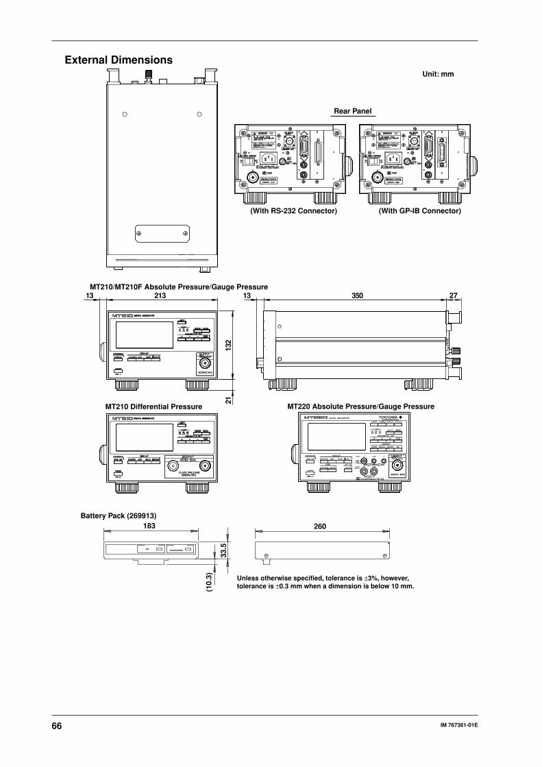
66 IM 767361-01E
External Dimensions
MT210 Differential Pressure
13 350 27
Unit: mm
(With RS-232 Connector) (With GP-IB Connector)
Rear Panel
260
33.5
(10.
3)
183
MT210/MT210F Absolute Pressure/Gauge Pressure
132
21
21313
Battery Pack (269913)
Unless otherwise specified, tolerance is ±3%, however, tolerance is ±0.3 mm when a dimension is below 10 mm.
MT220 Absolute Pressure/Gauge PressureDIGITAL MANOMETER
PRESSURE
ZERO CAL RELATIVE UNIT
DC5V/20mA ON/OFF ON/OFF
ALL TERMINALS 42V PEAK MAXBETWEEN TERMINALS AND GND.
FUSE250V
T 100mA
24VOUTPUT
24mA 6VMAX MAX
30mAMAX
HOLD TRIG
INPUT A COM
COM
V
POWER
DISPLAY
DMM 24V DC
LIGHT
COMP
MEMORY
DIGITS
STORE RECALL DELETE No.
HI IN LO
ENTER/LOCAL
MENU
PARAMETER SET
INPUTRANGE:10kPa
500kPa MAX
% Error AUTO 0% AUTO 100%
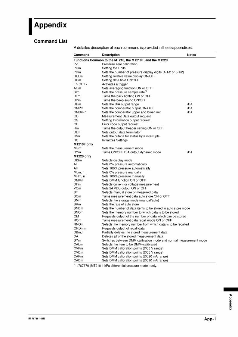
App-1IM 767361-01E
Ap
pen
dix
Appendix
Command ListA detailed description of each command is provided in these appendixes.
Command Description Notes
Functions Common to the MT210, the MT210F, and the MT220PZ Pressure zero calibrationPUm Setting the UnitsPDm Sets the number of pressure display digits (4-1/2 or 5-1/2)RELm Setting relative value display ON/OFFHDm Setting data hold ON/OFFE/<GET> Activates a triggerAGm Sets averaging function ON or OFFSIm Sets the pressure sample rate*1
BLm Turns the back lighting ON or OFFBPm Turns the beep sound ON/OFFDRm Sets the D/A output range /DACMPm Sets the comparator output ON/OFF /DACMDm,n Sets the comparator upper and lower limit /DAOD Measurement Data output requestOS Setting Information output requestOE Error code output requestHm Turns the output header setting ON or OFFDLm Sets output data terminatorIMm Sets the criteria for status byte interruptsRC Initializes SettingsMT210F onlyMSm Sets the measurement modeDYm Turns ON/OFF D/A output dynamic mode /DAMT220 onlyDISm Selects display modeAL Sets 0% pressure automaticallyAH Sets 100% pressure automaticallyMLm, n Sets 0% pressure manuallyMHm, n Sets 100% pressure manuallyDMMn Sets DMM function ON or OFFDFm Selects current or voltage measurementVOm Sets 24 VDC output ON or OFFST Selects manual store of measured dataSOm Turns measurement data auto store ON or OFFSMm Selects the storage mode (manual/auto)SRm Sets the rate of auto storeSNDm Sets the number of data items to be stored in auto store modeSNOm Sets the memory number to which data is to be storedOM Requests output of the number of data which can be storedROm Turns measurement data recall mode ON or OFFRNOm Selects the memory number from which data is to be recalledORDm,n Requests output of recall dataDBm,n Partially deletes the stored measurement dataDA Deletes all of the stored measurement dataSYm Switches between DMM calibration mode and normal measurement modeCALm Selects the item to be DMM–calibratedCVPm Sets DMM calibration points (DC5 V range)CVDm Sets DMM calibration points (DC5 V range)CAPm Sets DMM calibration points (DC20 mA range)CADm Sets DMM calibration points (DC20 mA range)
*1: 767370 (MT210 1 kPa differential pressure model) only.
App-2 IM 767361-01E
Description
• The 100% value cannot be
automatically set when in % or
%ERROR display mode. An error 15
occurs.
• Cannot be executed while displaying
the relative value. An error 15 occurs.
• Cannot execute in recall mode. An
error 14 occurs.
AL
Sets the current measured pressure value as
the 0% value.
Syntax
AL <terminator>
Description
• The 0% value cannot be automatically
set when in % or %ERROR display
mode. An error 15 occurs.
• Cannot be executed while displaying
the relative value. An error 15 occurs.
• Cannot execute in recall mode. An
error 14 occurs.
BL/BL?
Turns the back lighting function ON and OFF,
and queries the current setting.
Syntax
BLm<terminator>
“m” represents ON/OFF for the back
lighting.
0: OFF
1: ON
Query
BL?<terminator>
Response Example
BL0
BP/BP?
Queries the setting for the beep sound (the
sound when keys are pressed).
Syntax
BPm<terminator>
“m” represents the ON/OFF for the beep
sound setting.
0: OFF
1: ON
Communications Command ListAG/AG?
Turns the averaging function ON and OFF, and
queries the current setting.
Syntax
AGm <terminator>
“m” represents ON/OFF for the averaging
function.
For the MT210/MT210F
0: Averaging is OFF for pressure
measurement.
1: Averaging is ON for pressure
measurement.
For the MT220
0: Pressure averaging OFF
DMM averaging OFF
1: Pressure averaging ON
DMM averaging OFF
2: Pressure averaging OFF
DMM averaging ON
3: Pressure averaging ON
DMM averaging ON
Query
AG? <terminator>
Response Example
AG1
Description
• For the MT210F, averaging settings
are only valid for normal measurement
mode. The averaging function does
not work when in medium and high-
speed measurement modes so it
cannot be selected. An error 15
occurs.
• Pressure averaging ON(AG1) cannot
be selected when the pressure
sampling rate is 4 s (SI1) on the
767370 (1 kPa differential model). An
error 12 occurs.
• Cannot change in recall mode. An
error 14 occurs.
AH
Sets the current measured pressure value as
the 100% value.
Syntax
AH <terminator>

App-3IM 767361-01E
Ap
pen
dix
Query
BP?<terminator>
Response Example
BP1
CAD
Sets the value of the DC current in the
calibration point and queries the measurement
value of the input before calibration.
Syntax
CADm<terminator>
“m” represents the calibration value.
0 (CAP1) :0.0000 <fixed>
+FS(CAP2): 0.0000 to 24.0000
+FS(CAP3): -24.0000 to 0.0000
Response Example
A_N_20.0000
Description
• Error 11 occurs if the mode is not DMM
calibration mode.
• If the item to be calibrated is not set to
DC current (CAL2), an error 21 occurs.
• For the calibration value for calibration
point 0, set m to 0.
• For details regarding the calibration
procedure, refer to pages 57 and App-
18.
CAL/CAL?
Sets the DMM calibration item and queries the
current setting.
Syntax
CALm<terminator>
“m” represents the item to be calibrated.
0: Returns to normal measurement
mode.
1: DC voltage (5 V range)
2: DC voltage (20 mA range)
Query
CAL?<terminator>
Response Example
CAL1
Description
• Error 11 occurs if the mode is not DMM
calibration mode.
• For details regarding the calibration
procedure, refer to pages 57 and App-
18.
CAP/CAP?
Sets the calibration points for the DC current
(20 mA range), and queries the current setting.
Syntax for setting
CAPm<terminator>
“m” represents the calibration point.
0: After calibration, the correction
coefficient is calculated, then the result is
written to the EEPROM.
1: ( 0 mA)
2: +FS ( 20.0 mA)
3: -FS (-20 mA)
Query
CAP?<terminator>
Response Example
CAP1
Description
• Error 11 occurs if the mode is not DMM
calibration mode.
• If the item to be calibrated is not set to
DC current (CAL2), an error 21 occurs.
• If the three calibration points have not
been set when end (end of calibration)
is selected, calibration error 21 occurs.
Also, if the calculated correction
coefficient is not correct, calibration
error 22 occurs.
• For details regarding the calibration
procedure, refer to pages 57 and App-
18.
CMD/CMD?
Sets the upper and lower limit of the
comparator, and queries the current setting.
Syntax
CMDm,n<terminator>
“m” represents the comparator lower limit
“n” represents the comparator upper limit
The setting range and resolution for m
and n is the same as that of the pressure
measurement display.
Query
CMD?<terminator>
Response Example
CMD0.000,130.000 (for 130-kPa range
models)
App-4 IM 767361-01E
Description
• Only valid with the D/A output option
(/DA)
• The parameters are set in the order
lower limit, then upper limit. The
setting, Lower limit ≥ upper limit, is not
possible. An error 12 occurs.
CMP/CMP?
Turns comparator output ON/OFF, and queries
the current setting.
Syntax
CMPm<terminator>
“m” represents the comparator output
0: OFF
1: ON
Query
CMP?<terminator>
Response Example
CMP1
Description
Only valid with the D/A output option
(/DA)
CVD
Sets the value of the DC voltage (5-V range) in
the calibration point and queries the
measurement value of the input before
calibration.
Syntax
CVDm<terminator>
“m” represents the calibration value.
0 (CVP1) :0.0000 <fixed>
+FS(CVP2): 0.00000 to 6.00000
-FS(CVP3): -6.00000 to 0.00000
Response Example
V_N_5.0000
Description
• Error 11 occurs if the mode is not DMM
calibration mode.
• If the item to be calibrated is not set to
DC voltage (CAL1), an error 21 occurs.
• For the calibration value for calibration
point 0 (CVP1), set m to 0.
• For details regarding the calibration
procedure, refer to pages 57 and App-
18.
CVP/CVP?
Sets the calibration points for the DC voltage (5
V range), and queries the current setting.
Syntax
CVPm<terminator>
“m” represents the calibration point.
0: After calibration, the correction
coefficient is calculated, then the result
is written to the EEPROM.
1: 0(0V)
2: +FS (5 V)
3: -FS (-5 V)
Query
CVP?<terminator>
Response Example
CVP1
Description
• Error 11 occurs if the mode is not DMM
calibration mode.
• If the item to be calibrated is not set to
DC voltage (CAL1), an error 21 occurs.
• If the three calibration points have not
been set when end (end of calibration)
is selected, calibration error 21 occurs.
Also, if the calculated correction
coefficient is not correct, calibration
error 22 occurs.
• For details regarding the calibration
procedure, refer to pages 57 and App-
18.
DA
Deletes all the stored data.
Syntax
DA <terminator>
Description
Cannot be executed during auto store.
An error 14 occurs.
DB/DB?
Deletes the specified stored data.
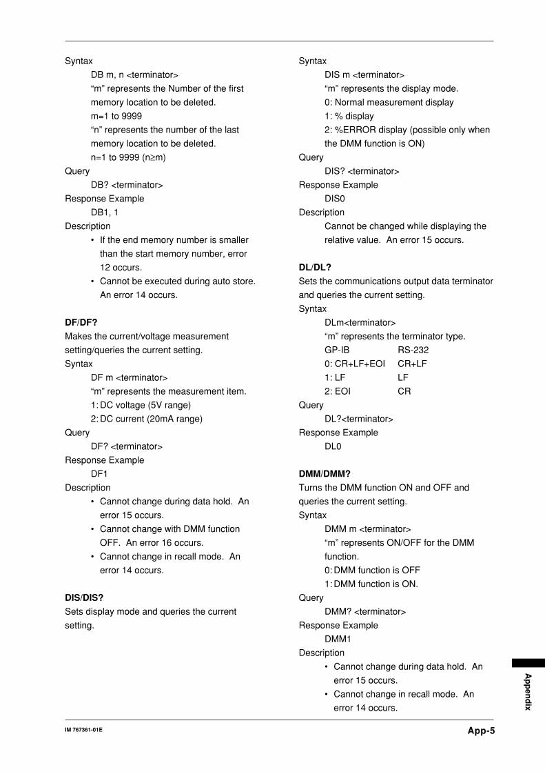
App-5IM 767361-01E
Ap
pen
dix
Syntax
DB m, n <terminator>
“m” represents the Number of the first
memory location to be deleted.
m=1 to 9999
“n” represents the number of the last
memory location to be deleted.
n=1 to 9999 (n≥m)
Query
DB? <terminator>
Response Example
DB1, 1
Description
• If the end memory number is smaller
than the start memory number, error
12 occurs.
• Cannot be executed during auto store.
An error 14 occurs.
DF/DF?
Makes the current/voltage measurement
setting/queries the current setting.
Syntax
DF m <terminator>
“m” represents the measurement item.
1: DC voltage (5V range)
2: DC current (20mA range)
Query
DF? <terminator>
Response Example
DF1
Description
• Cannot change during data hold. An
error 15 occurs.
• Cannot change with DMM function
OFF. An error 16 occurs.
• Cannot change in recall mode. An
error 14 occurs.
DIS/DIS?
Sets display mode and queries the current
setting.
Syntax
DIS m <terminator>
“m” represents the display mode.
0: Normal measurement display
1: % display
2: %ERROR display (possible only when
the DMM function is ON)
Query
DIS? <terminator>
Response Example
DIS0
Description
Cannot be changed while displaying the
relative value. An error 15 occurs.
DL/DL?
Sets the communications output data terminator
and queries the current setting.
Syntax
DLm<terminator>
“m” represents the terminator type.
GP-IB RS-232
0: CR+LF+EOI CR+LF
1: LF LF
2: EOI CR
Query
DL?<terminator>
Response Example
DL0
DMM/DMM?
Turns the DMM function ON and OFF and
queries the current setting.
Syntax
DMM m <terminator>
“m” represents ON/OFF for the DMM
function.
0: DMM function is OFF
1: DMM function is ON.
Query
DMM? <terminator>
Response Example
DMM1
Description
• Cannot change during data hold. An
error 15 occurs.
• Cannot change in recall mode. An
error 14 occurs.

App-6 IM 767361-01E
DR/DR?
Sets the D/A output range, and queries the
current setting.
Syntax
DRm<terminator>
“m” represents the D/A output range
0: ±2 VDC
1: ±5 VDC
Query
DR?<terminator>
Response Example
DR0
Description
Only valid with the D/A output option
(/DA)
DY/DY?
Turns D/A output dynamic mode ON/OFF and
queries the current setting.
Syntax
DYm<terminator>
“m” represents D/A output dynamic mode
0: OFF
1: ON
Query
DY?<terminator>
Response Example
DY0
Description
• Only valid with the D/A output option
(/DA) on the MT210F.
• On the MT210/MT210F, it is fixed to
OFF(DY0)It cannot be set to ON(DY1).
E, <interface message GET>
Activates a trigger.
Syntax
E<terminator>
<interface message GET>
Description
Only applicable when data is on hold. An
error 15 occurs.
H/H?
Sets whether the header is added to the
measurement data output via communications
and queries the current setting.
Syntax
Hm<terminator>
“m” represents the header setting.
0: OFF (no header)
1: ON (header is added)
Query
H?<terminator>
Response Example
H1
HD/HD?
Sets the data hold and queries the current
setting.
Syntax
HDm<terminator>
“m” represents the state of data hold.
0: Data hold is OFF.
1: Data hold is ON.
Query
HD?<terminator>
Response Example
HD0
IM/IM?
Sets the criteria for a status byte interrupt and
queries the current setting.
Syntax
IMm<terminator>
“m” is the cause for the interrupt, (0 to
31).
1: Computation END
2: Auto store END(only for MT220)
4: Syntax error
8: OVER
16: 24 VOUT-OL- (MT220 only)
Query
IM?<terminator>
Response Example
IM31
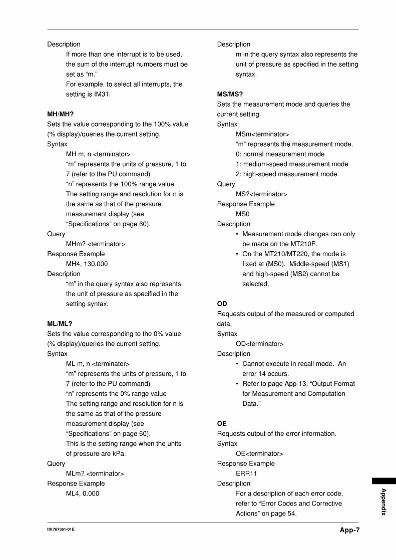
App-7IM 767361-01E
Ap
pen
dix
Description
If more than one interrupt is to be used,
the sum of the interrupt numbers must be
set as “m.”
For example, to select all interrupts, the
setting is IM31.
MH/MH?
Sets the value corresponding to the 100% value
(% display)/queries the current setting.
Syntax
MH m, n <terminator>
“m” represents the units of pressure, 1 to
7 (refer to the PU command)
“n” represents the 100% range value
The setting range and resolution for n is
the same as that of the pressure
measurement display (see
“Specifications” on page 60).
Query
MHm? <terminator>
Response Example
MH4, 130.000
Description
“m” in the query syntax also represents
the unit of pressure as specified in the
setting syntax.
ML/ML?
Sets the value corresponding to the 0% value
(% display)/queries the current setting.
Syntax
ML m, n <terminator>
“m” represents the units of pressure, 1 to
7 (refer to the PU command)
“n” represents the 0% range value
The setting range and resolution for n is
the same as that of the pressure
measurement display (see
“Specifications” on page 60).
This is the setting range when the units
of pressure are kPa.
Query
MLm? <terminator>
Response Example
ML4, 0.000
Description
m in the query syntax also represents the
unit of pressure as specified in the setting
syntax.
MS/MS?
Sets the measurement mode and queries the
current setting.
Syntax
MSm<terminator>
“m” represents the measurement mode.
0: normal measurement mode
1: medium-speed measurement mode
2: high-speed measurement mode
Query
MS?<terminator>
Response Example
MS0
Description
• Measurement mode changes can only
be made on the MT210F.
• On the MT210/MT220, the mode is
fixed at (MS0). Middle-speed (MS1)
and high-speed (MS2) cannot be
selected.
OD
Requests output of the measured or computed
data.
Syntax
OD<terminator>
Description
• Cannot execute in recall mode. An
error 14 occurs.
• Refer to page App-13, “Output Format
for Measurement and Computation
Data.”
OE
Requests output of the error information.
Syntax
OE<terminator>
Response Example
ERR11
Description
For a description of each error code,
refer to “Error Codes and Corrective
Actions” on page 54.

App-8 IM 767361-01E
OM
Requests output of the number of data items it
is possible to store.
Syntax
OM <terminator>
Response Example
FREE2000 <terminator>
ORD
Requests output of the recall data.
Syntax
ORDm, n <terminator>
“m” represents the number of the first
memory location to be recalled.
m=1 to 9999
“n” represents the number of the last
memory location to be recalled.
n=1 to 9999(n≥m)
Description
• Cannot execute unless in recall mode.
An error 15 occurs.
• 100 data can be output at one time. If
a memory data higher than 100 is
specified, only the first 100 data will be
output.
• If the end memory number is smaller
than the start memory number, error
12 occurs.
• Refer to page App-15, “Output Format
for Recall Data.”
OS
Requests output of the setting information.
Syntax
OS<terminator>
Description
Refer to page App-15, “Output Format for
Panel Setting Information.”
PD/PD?
Sets the number of display digits for the
measured pressure value and the value to be
displayed in %, and queries the current setting.
Syntax
PDm<terminator>
“m” represents the number of display
digits.
0: Measured pressure value in 5-1/2
digits, % value in 4-1/2 digits
1: Measured pressure value in 4-1/2
digits, % value in 3-1/2 digits
Query
PD?<terminator>
Response Example
PD0
Description
In the case of 700 kPa models (767355/
767365/767373/767385), “m” represents
the number of display digits as follows:
0: Measured pressure value in 4-1/2
digits, % value in 4-1/2 digits
1: Measured pressure value in 3-1/2
digits, % value in 3-1/2 digits
PU/PU?
Sets the units of pressure and queries the
current setting.
Syntax
PUm<terminator>
The value “m” is the unit of pressure.
1: inH20 (available with the -U3 model)
2: inHg (available with the -U3 model)
3: psi (available with the -U3 model)
4: kPa
5: kgf/cm2 (available with the -U2 and -
U3 models)
6: mmH20 (available with the -U2 and -
U3 models)
7: mmHg (available with the -U2 and -
U3 models)
Query
PU?<terminator>
Response Example
PU4
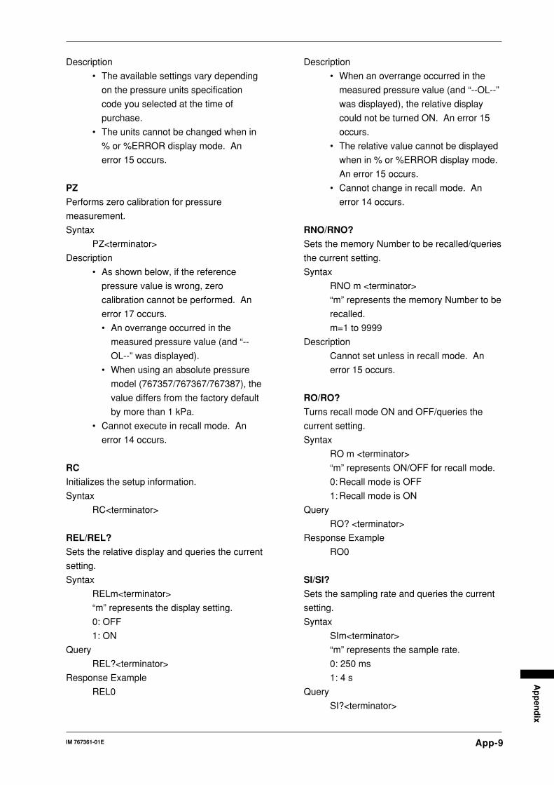
App-9IM 767361-01E
Ap
pen
dix
Description
• The available settings vary depending
on the pressure units specification
code you selected at the time of
purchase.
• The units cannot be changed when in
% or %ERROR display mode. An
error 15 occurs.
PZ
Performs zero calibration for pressure
measurement.
Syntax
PZ<terminator>
Description
• As shown below, if the reference
pressure value is wrong, zero
calibration cannot be performed. An
error 17 occurs.
• An overrange occurred in the
measured pressure value (and “--
OL--” was displayed).
• When using an absolute pressure
model (767357/767367/767387), the
value differs from the factory default
by more than 1 kPa.
• Cannot execute in recall mode. An
error 14 occurs.
RC
Initializes the setup information.
Syntax
RC<terminator>
REL/REL?
Sets the relative display and queries the current
setting.
Syntax
RELm<terminator>
“m” represents the display setting.
0: OFF
1: ON
Query
REL?<terminator>
Response Example
REL0
Description
• When an overrange occurred in the
measured pressure value (and “--OL--”
was displayed), the relative display
could not be turned ON. An error 15
occurs.
• The relative value cannot be displayed
when in % or %ERROR display mode.
An error 15 occurs.
• Cannot change in recall mode. An
error 14 occurs.
RNO/RNO?
Sets the memory Number to be recalled/queries
the current setting.
Syntax
RNO m <terminator>
“m” represents the memory Number to be
recalled.
m=1 to 9999
Description
Cannot set unless in recall mode. An
error 15 occurs.
RO/RO?
Turns recall mode ON and OFF/queries the
current setting.
Syntax
RO m <terminator>
“m” represents ON/OFF for recall mode.
0: Recall mode is OFF
1: Recall mode is ON
Query
RO? <terminator>
Response Example
RO0
SI/SI?
Sets the sampling rate and queries the current
setting.
Syntax
SIm<terminator>
“m” represents the sample rate.
0: 250 ms
1: 4 s
Query
SI?<terminator>
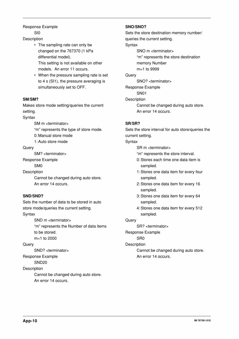
App-10 IM 767361-01E
Response Example
SI0
Description
• The sampling rate can only be
changed on the 767370 (1 kPa
differential model).
This setting is not available on other
models. An error 11 occurs.
• When the pressure sampling rate is set
to 4 s (SI1), the pressure averaging is
simultaneously set to OFF.
SM/SM?
Makes store mode setting/queries the current
setting.
Syntax
SM m <terminator>
“m” represents the type of store mode.
0: Manual store mode
1: Auto store mode
Query
SM? <terminator>
Response Example
SM0
Description
Cannot be changed during auto store.
An error 14 occurs.
SND/SND?
Sets the number of data to be stored in auto
store mode/queries the current setting.
Syntax
SND m <terminator>
“m” represents the Number of data items
to be stored.
m=1 to 2000
Query
SND? <terminator>
Response Example
SND20
Description
Cannot be changed during auto store.
An error 14 occurs.
SNO/SNO?
Sets the store destination memory number/
queries the current setting.
Syntax
SNO m <terminator>
“m” represents the store destination
memory Number
m=1 to 9999
Query
SNO? <terminator>
Response Example
SN01
Description
Cannot be changed during auto store.
An error 14 occurs.
SR/SR?
Sets the store interval for auto store/queries the
current setting.
Syntax
SR m <terminator>
“m” represents the store interval.
0: Stores each time one data item is
sampled.
1: Stores one data item for every four
sampled.
2: Stores one data item for every 16
sampled.
3: Stores one data item for every 64
sampled.
4: Stores one data item for every 512
sampled.
Query
SR? <terminator>
Response Example
SR0
Description
Cannot be changed during auto store.
An error 14 occurs.

App-11IM 767361-01E
Ap
pen
dix
SO/SO?
Sets whether to start or stop data storage in
auto store mode/queries the current setting.
Syntax
SO m <terminator>
“m” represents whether data storage is to
be started or stopped.
0: Stops (aborts) data storage.
1: Starts data storage.
Query
SO? <terminator>
Response Example
SO0
Description
• Cannot execute in manual store mode.
An error 14 occurs.
• Cannot change in recall mode. An
error 14 occurs.
ST
Stores data in manual store mode.
Syntax
ST <terminator>
Description
• Cannot execute in auto store mode.
An error 14 occurs.
• Cannot execute in recall mode. An
error 14 occurs.
SY/SY?
Sets DMM calibration mode and normal
measurement mode and queries the current
setting.
Syntax
SYm<terminator>
“m” represents the system mode.
0: Normal measurement mode
1: DMM calibration mode
Query
SY? <terminator>
Response Example
SY0
Description
• DMM calibration mode cannot be set if
the DMM function is OFF. An error 16
occurs.
• DMM calibration mode cannot be set
when data is on hold. An error 15
occurs.
• DMM calibration mode cannot be set
when in recall mode. An error 14
occurs.
VO/VO?
Turns 24 VDC output ON and OFF and queries
the current setting.
Syntax
VO m <terminator>
“m” represents ON/OFF of 24 VDC
output.
0: 24 VDC output is OFF
1: 24 VDC output is ON
Query
VO? <terminator>
Response Example
VDO

App-12 IM 767361-01E
Status Byte FormatGP-IB (Response to the Serial Poll)
DI08 DI07 DI06 DI05 DI04 DI03 DI02 DI01
0(fixed)
SRQ ERROR OVERSyntax
Error
24 VOUT
-OL-
Calcula-tionEND
AutostoreEND
SRQ (DIO 7)
This bit is set to 1 when a computation END, syntax ERROR, or OVER occurs,
and SRQ is set to True, thereby issuing a service request to the controller.
ERROR (DIO 6)
When a syntax ERROR, or OVER occurs, this bit is set to 1.
24VOUT-OL- (DIO 5)
When an overload occurs while 24 VDC is being output, thereby forcing the 24
VDC output to turn OFF, this bit is set to 1.
OVER (DIO 4)
This bit is set to 1 when an overrange occurs in the measured data or when a
computation overflow occurs. The status of OVER can be identified using the
OE command.
Syntax ERROR (DIO 3)
This bit is set to 1 when a command error, parameter error, or execution error
occurs. The nature of the syntax error can be identified using the OE
command.
Auto store END (DIO 2)
This bit is set to 1 when the measured or computed data has been stored in
auto store mode.
Computation END (DIO 1)
This bit is set to 1 when computation has been completed and the display is
updated.
Note• After the status byte responds to the serial poll from the controller, this bit is reset to 0. Until
the serial poll is responded to, each interrupt is stored, and if more interrupts occur thereafter,
they are added.
• To prevent the SRQ and status byte being affected by a computation END, syntax ERROR,
or OVER, use the IM command to set a value with the corresponding bits set to 0.
• When you are creating a communications program using the status byte, make sure that the
SRQ bit is set to 1 as well as the bit corresponding to the interrupt. In this way you can
acknowledge interrupts by issuing a serial poll continuously, instead of by using an SRQ
interrupt.

App-13IM 767361-01E
Ap
pen
dix
RS-232 (Response to the <ESC>S Command)
DI08 DI07 DI06 DI05 DI04 DI03 DI02 DI01
0(fixed)
1(fixed)
ERROR OVERSyntax
Error
24 VOUT
-OL-
Calcula-tionEND
AutostoreEND
For DIO1 to DIO6, the status byte format is identical to that used for the GP-IB
interface. For details, refer to page App-12.
Note• After the status byte responds to the serial poll from the controller, this bit is reset to 0. Until
the serial poll is responded to, each interrupt is stored, and if more interrupts occur thereafter,
they are added.
• To prevent the status byte being affected by a computation END, syntax ERROR, or OVER,
use the “IM” command to set a value with the corresponding bits set to 0.
Data Output FormatOutput Format for Measurement and Computation Data (Response to the “OD” Command)
Data Format
Each data consists of a 4-byte header and 8 bytes of data.
You can specify whether a header is output using the H command.
Header Data
Header SectionThe header section consists of four bytes (h1 to h4). indicates a space.
h1 h2 h3 h4
h1 to h3: Data type h4: Data state
KPA : Pressure (kPa) N : Normal measured data
KGF : Pressure (kgf/cm 2) I : Overrange data
MHO : Pressure (mmH 20) O : Computation overflow
MHG : Pressure (mmHg) E : No data
IHO : Pressure (inH 20)
IHG : Pressure (inHg)
PSI : Pressure (psi)
PP : Pressure %
DMM Header (MT220 Only)
h1 to h3: Data type h4: Data state
V : DC voltage (V) N : Normal measured data
A : DC current (mA) I : Overrange data
PV : DC voltage % O : Computation overflow
PA : DC current % F : No DMM data when DMM function is off
ERR : Error % E : No data

App-14 IM 767361-01E
Data Section
The data section consists of 8 bytes (d1 to d8).
d1 d2 d3 d4 d5 d6 d7 d8
d1: Polarity, (space), or – (minus)
d2 to d8: Up to 6 digits + decimal point
Data state in the case of an overrange (“ ” is displayed.)
h1 h2 h3 I 9 9 9 9 9 9 .
Data state in the case of a computation overflow (“ ”, “ ” is
displayed.)
h1 h2 h3 0 8 8 8 8 8 8 .
Data state when there is no data (“ ” is displayed.)
h1 h2 h3 E 8 8 8 8 8 8 .
Data state on the DMM side when the DMM function is off
h1 h2 h3 F 8 8 8 8 8 8 .
Output Format
For the MT210/MT210F
Pressure header Pressure data Terminator
Output Examples
KPAN 130.000
For the MT220
Pressure header Pressure data , DMM header DMM data Terminator
Output Examples
• Normal measurement
KPAN 130.000, V N 04.0000
• % display
PP N 0100.00, PV N 0075.00
• Error display
PP N 0100.00, ERRN 0025.00
• DMM function OFF, normal display
KPAN 130.000, V F 888888.
• Normal display (no header)
130.000, 05.0000

App-15IM 767361-01E
Ap
pen
dix
Output Format for Recalled Data (Response to the “ORD” Command, MT220Only)Data Number
h1 h2 h3 h4 d1 d2 d3 d4
h1-h3
NO. : Recall data number
h4
: Recall data is present.
E : No recall data is present.
d1-d4
4 digit number (recall data number)
Output Format
Pressure data
Pressure header ,Data
number, DMM dataDMM header Terminator
Output Examples
• DMM function OFF, normal display of recall data
NO. 0001, KPAN 130.000, V N 05.0000
• No recall data
NO.E0002, KPAE 888888., V E 888888.
Output Format of Setup Information (Response to the “OS” Command)For the MT210/MT210F
1st line: Model, software version number.
2nd line: Pressure setup information
3rd line: Measurement condition
4th line: Backlight and beep
5th line *1: D/A output and comparator settings
6th line: Output end*1: Line 5 is output only when the D/A output option (/DA) is installed.
Example of response
MDL767313;REV1.01
REL0;PU4;PD0
HD0;AG1
BL0;BP1
DR0;CMP0;CMD0.000,130.000
END
For the MT220
1st line: Model, software version number
2nd line: Pressure set-up information
3rd line: DMM set-up information
4th line: Measurement conditions
5th line: Power output, back light, beep
6th line: Data memory function
7th line *2: D/A output and comparator settings
8th line: Output end*2: 7th line output only with the D/A output option (/DA) installed

App-16 IM 767361-01E
Example of response
MDL767303;REV1.01
REL0;PU4;PD0;ML4,0.000;MH4,130.000
DMM1;DF1
HD0;AG3;DIS0
VO0L;BL0;BP1
SM0;SN01;SR0;SND20
DR0;CMP0;CMD0.000,130.000
END
Sample ProgramOperating Environment
Target model: NEC PC-9801 Series
Target language: N88-BASIC (standard program language on the PC-9801
Series)
GP-IB board: PC-9801-29N interface board
10 '*************************************************************************
20 '* Program that reads/displays the measured data 10 times (GP-IB)' *
30 '*************************************************************************
40 '
100 ISET IFC ' interface/clear
110 ISET REN ' set remote
120 CMD DELIM=0 'controller side delimiter = CR+LF
130 IO=1 'Address=1
140 '
150 PRINT @IO;"PU4" 'Pressure units = kPa
160 PRINT @IO;"H1" 'Communications output data header present
170 PRINT @IO;"DL0" 'Communications output delimiter=CR+LF+EOI
180 '
190 FOR I=1 TO 10 'read measured data ten times
200 INPUT WAIT 10," ",A 'wait (random)
210 PRINT @IO;"OD" 'measured data output request
220 LINE INPUT @IO;D$ 'read measured data
230 PRINT D$ 'display measured data
240 NEXT I
250 '
260 '
300 '************************************************************************
310 '* Program that reads data using trigger and serial poll (GP-IB)' *
320 '************************************************************************
330 '
340 PRINT @IO;"HD1" 'data hold
350 '
360 PRINT @IO;"IM1" 'status byte mask
370 POLL IO,STB 'status byte initialization
380 '
390 FOR I=1 TO 10 'read measured data ten times
400 PRINT @IO;"E" 'activates trigger
410 POLL IO,STB 'send serial poll
420 IF (STB AND &H41)<>&H41 THEN 410 'check whether measurement has finished
430 PRINT @IO;"OD" 'measured data output request
440 LINE INPUT @IO;D$ 'read measured data
450 PRINT D$ 'display measured data
460 NEXT I
470 '
480 PRINT @IO;"HD0" 'release data hold

App-17IM 767361-01E
Ap
pen
dix
490 '
500 IRESET REN 'cancel remote
510 STOP 'exit
520 END
10 '*************************************************************************
20 '* Program that reads/displays the measured data 10 times (RS-232) *
30 '*************************************************************************
40 '
100 OPEN "COM:N81NN" AS #1 'open line
110 PRINT #1,CHR$(&H1B)+"R" 'set remote
120 '
130 PRINT #1,"PU4" 'pressure units = kPa
140 PRINT #1,"H1" 'communications output data header present
150 PRINT #1,"DL0" 'communications output delimiter=CR+LF
160 '
170 FOR I=1 TO 10 'read measured data ten times
180 INPUT WAIT 10," ",A 'wait (random)
190 PRINT #1,"OD" 'measured data output request
200 LINE INPUT #1,D$ 'read measured data
210 PRINT D$ 'display measured data
220 NEXT I
230 '
240 '
300 '******************************************************************
310 '* Program that reads data using trigger and serial poll (RS-232) *
320 '******************************************************************
330 '
340 PRINT #1,"HD1" 'data hold
350 '
360 PRINT #1,"IM1" 'status byte mask
370 PRINT #1,CHR$(&H1B)+"S" 'status byte initialization
380 LINE INPUT #1,B$
390 '
400 FOR I=1 TO 10 'read measured data ten times
410 PRINT #1,"E" 'activates trigger.
420 PRINT #1,CHR$(&H1B)+"S" 'read status byte
430 LINE INPUT #1,B$
440 STB=ASC(LEFT$(B$,1))
450 IF (STB AND &H41)<>&H41 THEN 420 'check whether measurement has finished
460 PRINT #1,"OD" 'measured data output request
470 LINE INPUT #1,D$ 'read measured data
480 PRINT D$ 'display measured data
490 NEXT I
500 '
510 PRINT #1,"HD0" 'release data hold
520 '
530 PRINT #1,CHR$(&H1B)+"L" 'cancel remote
540 CLOSE #1 'close line
550 '
560 STOP 'exit
570 END
10 '***********************************************************
20 '* DMM calibration program (voltage calibration) *
30 '***********************************************************
40 '
100 ISET IFC ISET REN 'set remote
110 CMD DELIM=0: IO=1 'address=1
120 '
130 POLL IO,STB 'status byte initialization
140 PRINT @IO;"IM4" 'status byte mask
150 '
160 PRINT @IO;"SY1" : INPUT WAIT 10," ",A 'enter calibration mode
170 PRINT @IO;"CAL1" ' calibrating the voltage
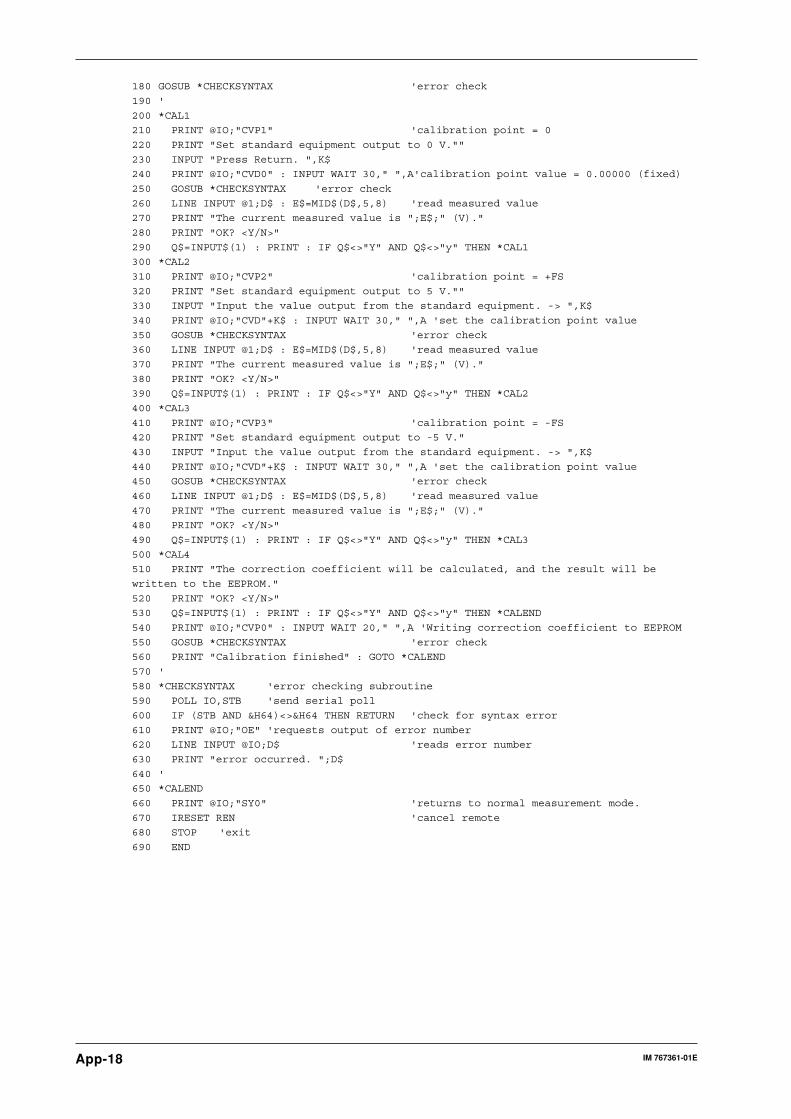
App-18 IM 767361-01E
180 GOSUB *CHECKSYNTAX 'error check
190 '
200 *CAL1
210 PRINT @IO;"CVP1" 'calibration point = 0
220 PRINT "Set standard equipment output to 0 V.""
230 INPUT "Press Return. ",K$
240 PRINT @IO;"CVD0" : INPUT WAIT 30," ",A'calibration point value = 0.00000 (fixed)
250 GOSUB *CHECKSYNTAX 'error check
260 LINE INPUT @1;D$ : E$=MID$(D$,5,8) 'read measured value
270 PRINT "The current measured value is ";E$;" (V)."
280 PRINT "OK? <Y/N>"
290 Q$=INPUT$(1) : PRINT : IF Q$<>"Y" AND Q$<>"y" THEN *CAL1
300 *CAL2
310 PRINT @IO;"CVP2" 'calibration point = +FS
320 PRINT "Set standard equipment output to 5 V.""
330 INPUT "Input the value output from the standard equipment. -> ",K$
340 PRINT @IO;"CVD"+K$ : INPUT WAIT 30," ",A 'set the calibration point value
350 GOSUB *CHECKSYNTAX 'error check
360 LINE INPUT @1;D$ : E$=MID$(D$,5,8) 'read measured value
370 PRINT "The current measured value is ";E$;" (V)."
380 PRINT "OK? <Y/N>"
390 Q$=INPUT$(1) : PRINT : IF Q$<>"Y" AND Q$<>"y" THEN *CAL2
400 *CAL3
410 PRINT @IO;"CVP3" 'calibration point = -FS
420 PRINT "Set standard equipment output to -5 V."
430 INPUT "Input the value output from the standard equipment. -> ",K$
440 PRINT @IO;"CVD"+K$ : INPUT WAIT 30," ",A 'set the calibration point value
450 GOSUB *CHECKSYNTAX 'error check
460 LINE INPUT @1;D$ : E$=MID$(D$,5,8) 'read measured value
470 PRINT "The current measured value is ";E$;" (V)."
480 PRINT "OK? <Y/N>"
490 Q$=INPUT$(1) : PRINT : IF Q$<>"Y" AND Q$<>"y" THEN *CAL3
500 *CAL4
510 PRINT "The correction coefficient will be calculated, and the result will be
written to the EEPROM."
520 PRINT "OK? <Y/N>"
530 Q$=INPUT$(1) : PRINT : IF Q$<>"Y" AND Q$<>"y" THEN *CALEND
540 PRINT @IO;"CVP0" : INPUT WAIT 20," ",A 'Writing correction coefficient to EEPROM
550 GOSUB *CHECKSYNTAX 'error check
560 PRINT "Calibration finished" : GOTO *CALEND
570 '
580 *CHECKSYNTAX 'error checking subroutine
590 POLL IO,STB 'send serial poll
600 IF (STB AND &H64)<>&H64 THEN RETURN 'check for syntax error
610 PRINT @IO;"OE" 'requests output of error number
620 LINE INPUT @IO;D$ 'reads error number
630 PRINT "error occurred. ";D$
640 '
650 *CALEND
660 PRINT @IO;"SY0" 'returns to normal measurement mode.
670 IRESET REN 'cancel remote
680 STOP 'exit
690 END
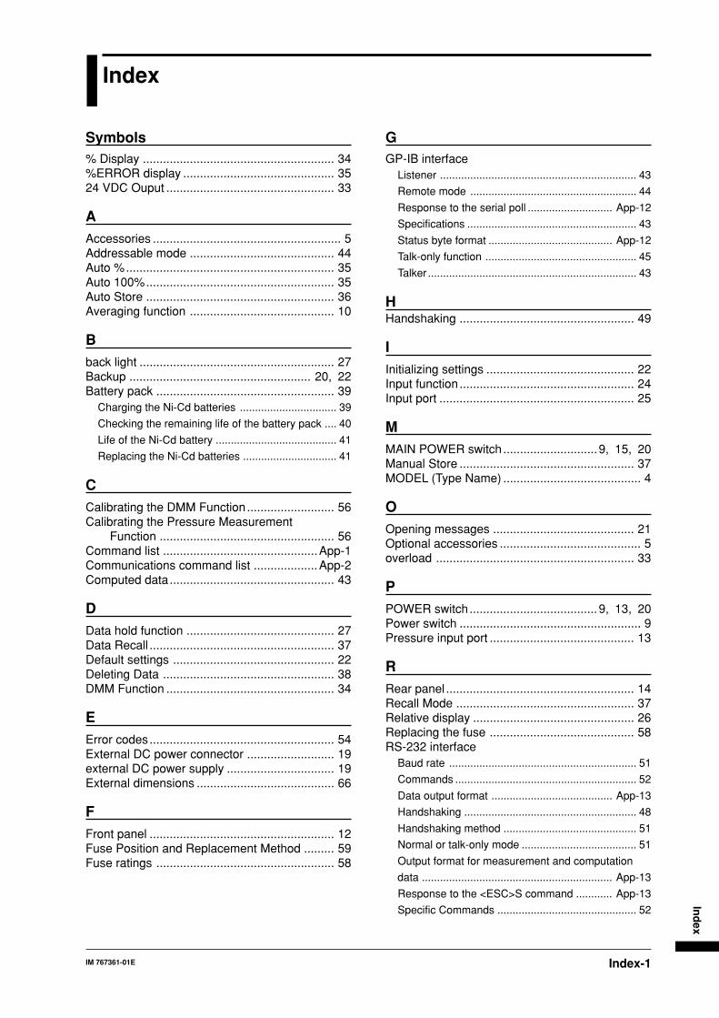
Index-1IM 767361-01E
Ind
ex
Index
Symbols% Display ......................................................... 34%ERROR display ............................................. 3524 VDC Ouput .................................................. 33
AAccessories ........................................................ 5Addressable mode ........................................... 44Auto %.............................................................. 35Auto 100%........................................................ 35Auto Store ........................................................ 36Averaging function ........................................... 10
Bback light .......................................................... 27Backup ...................................................... 20, 22Battery pack ..................................................... 39
Charging the Ni-Cd batteries ................................ 39
Checking the remaining life of the battery pack .... 40
Life of the Ni-Cd battery ........................................ 41
Replacing the Ni-Cd batteries ............................... 41
CCalibrating the DMM Function .......................... 56Calibrating the Pressure Measurement
Function .................................................... 56Command list ..............................................App-1Communications command list ...................App-2Computed data................................................. 43
DData hold function ............................................ 27Data Recall ....................................................... 37Default settings ................................................ 22Deleting Data ................................................... 38DMM Function .................................................. 34
EError codes....................................................... 54External DC power connector .......................... 19external DC power supply ................................ 19External dimensions ......................................... 66
FFront panel ....................................................... 12Fuse Position and Replacement Method ......... 59Fuse ratings ..................................................... 58
GGP-IB interface
Listener ................................................................. 43
Remote mode ....................................................... 44
Response to the serial poll ............................ App-12
Specifications ........................................................ 43
Status byte format ......................................... App-12
Talk-only function .................................................. 45
Talker ..................................................................... 43
HHandshaking .................................................... 49
IInitializing settings ............................................ 22Input function .................................................... 24Input port .......................................................... 25
MMAIN POWER switch ............................9, 15, 20Manual Store .................................................... 37MODEL (Type Name) ......................................... 4
OOpening messages .......................................... 21Optional accessories .......................................... 5overload ........................................................... 33
PPOWER switch...................................... 9, 13, 20Power switch ...................................................... 9Pressure input port ........................................... 13
RRear panel ........................................................ 14Recall Mode ..................................................... 37Relative display ................................................ 26Replacing the fuse ........................................... 58RS-232 interface
Baud rate .............................................................. 51
Commands ............................................................ 52
Data output format ........................................ App-13
Handshaking ......................................................... 48
Handshaking method ............................................ 51
Normal or talk-only mode ...................................... 51
Output format for measurement and computation
data ............................................................... App-13
Response to the <ESC>S command ............ App-13
Specific Commands .............................................. 52
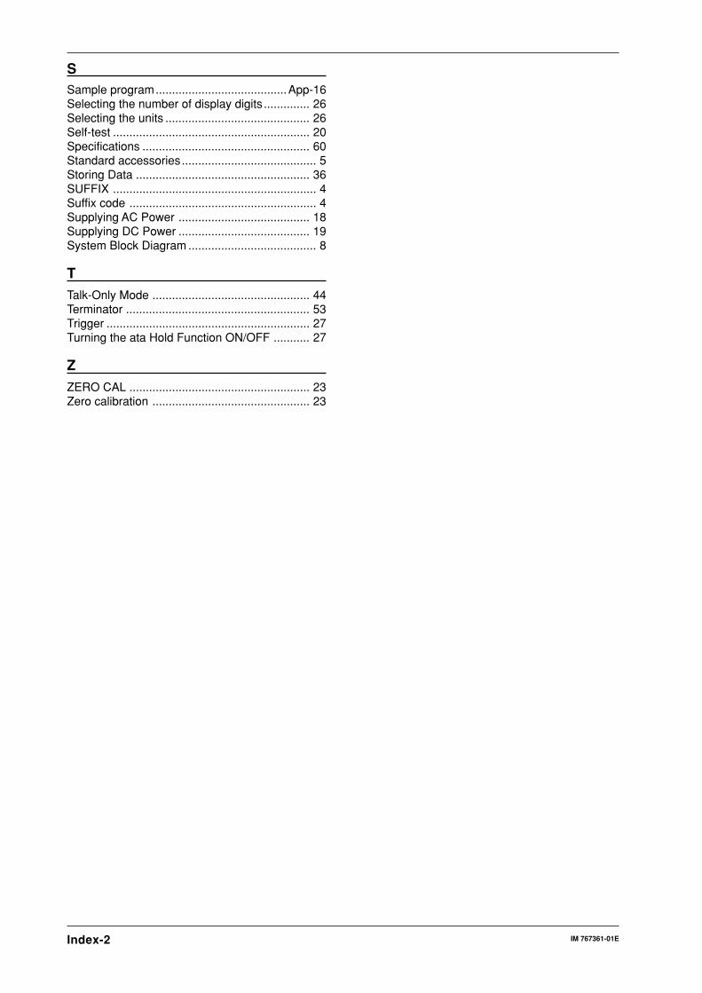
Index-2 IM 767361-01E
SSample program........................................App-16Selecting the number of display digits .............. 26Selecting the units ............................................ 26Self-test ............................................................ 20Specifications ................................................... 60Standard accessories......................................... 5Storing Data ..................................................... 36SUFFIX .............................................................. 4Suffix code ......................................................... 4Supplying AC Power ........................................ 18Supplying DC Power ........................................ 19System Block Diagram ....................................... 8
TTalk-Only Mode ................................................ 44Terminator ........................................................ 53Trigger .............................................................. 27Turning the ata Hold Function ON/OFF ........... 27
ZZERO CAL ....................................................... 23Zero calibration ................................................ 23