Embed Size (px)
Citation preview

XXXXX
https://ntrs.nasa.gov/search.jsp?R=19850027415 2019-04-17T00:41:46+00:00Z
• I 1. _n No. 2. Go_,Qmt_mtA_O.,_ No. 3. Pl_:p,ont s Cmts_ogNO
W_SA CR-174696' 4. Titre _ S.C,,tie S. ko_on Oa;e
APPLICABILITYOF 100kWe - CLASS OF SPACE REACTORPOWER SYSTEMS TO NASA MANNED SPACE STATION MISSIONS August 1984
I PertOrmmgOrgln_zlt_onCo_e
7. AutlW_I| I. Iq_rf_mg OrganUUi_*onR_OM NO
Sidney W. Silverman D180-28461-IDr. Harvey J. WillenbergCharles Robertson (General Electric Co.} _O.W_'u,,,No
,._,_ 0_,._,,__,_ AO_,,,Boeing Aerospace Company 11. GontractorGmntNo
Electrical Power Systems Technology NA-_ 3-23865EngineeringTechnology, PO Box 3999Seattle, Washington .98124 _.
,__,_,_ *w_ N,_ _w_Ac_,. Contractor ReportNASA Lewis Research Center2_000 Brookpark Ro_d 14.sao.,_.o _cy Co=,Cleveland, Ohio 44135
1S.$uDpltrmmt|_ N¢Nn
Project Manager, Jack A. HellerNASA Lewis Research CenterCleveland,Ohio
1'6,AbetmCt
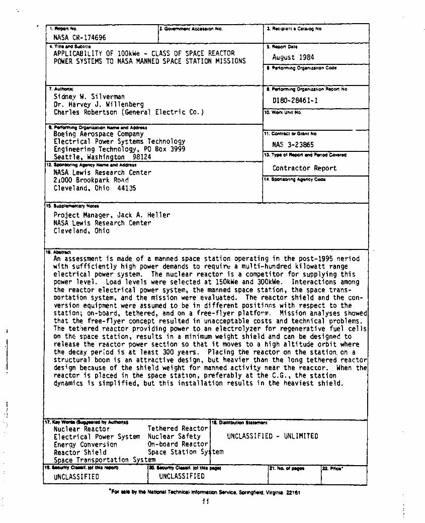
An assessment is made of a manned space station operating in the post-1995 neriodwith sufficientlyhigh power demands to requir_ a multi-hundred kilowatt rangeelectricalpower system. The nuclear reactor is a competitor for supplying thispower level. Load levels were selected at 150kWe and 300kWe. Interactionsamongthe reactor electrical power system, the manned space station, the space trans-oortation system, and the mission were evaluated. The reactor shield and the con-version equipmentwere assumed to be in different positinns with respect to thestation; on-board, tethered, and on a free-flyer platform. Mission analyses showedthat the free-flyerconcept resulted in unacceptable costs and technical problems.The tet:leredreactor providing power to an electrolyzer for regenerative fuel cellson the space station, results in a minimum weight shield and can be designed torelease the reactor power section so that it moves to a high altitude orbit wherethe decay period is at least 300 years. Placing the reactor on the station,on astructural boom is an attractive design, but heavier than the long tethered reactordesign because of the shield weight for manned activity near the reactor. When thereactor is placed in the space statlon, preferably at the C.G., the stationdynamics is simplified, but this installationresults in the heaviest shield.
17. Key'We_Is (SugdeetN _ _t_qol 1L Olom_tlon 'Smtem_mt
Nuclear Reactor Tethered ReactorElectricalPower System Nuclear Safety UNCLASSIFIED- UNLIMITEDEnergy Conversion On-board ReactorReactor Shield Space Station Sy!;tem
Space TransportationS_stem
UNCLASSIFIED UNCLASSIFIED
*F_ _ _ the NIItlOnlll T_hnlclll I_mltton Serv_o, Sgrlngf_, Vlrgtn_ _161
i
1985027415

FOREWARD
This contract report was prepared by the authors identified on the title page.Gordon R. Woodcock of Boeing Aerospace Company also provided guidance andcontributions to the program with respect to space station mission and operationalconcepts.
The Boeing contract manager was Sidney W. Silverman and the technical leaderwas Dr. Harvey 3. Willenberg. Information about the nuclear reactor powerconcepts_ hardware, and design and operation was prepared in a subcontract toBoeing by Charles Robertson under the management of William Terrill of GeneralElectric Company at King of Prussiaj PA.
At NASA Lewis Research Center9 3ack A. Heller was the project manager_ who hadsignificant assistance from 3oseph 3. Nainiger and Dr. 3ohn Dunning of the spacesystems office.
ttt
1985027415-002

LLSTOF ABBREVIATIONS
CDG Concept Detirdtion Group
CFE Continuous Flow Electrophoresis Process
DSCG Directional Solidification Crystal Growth
ECG Electroepitaxial Crystal Gr_wth
ECLSS Environmental Control/Life Support System
ED EngineeringDemonstration
EOS Electrophoresis Operations in Space
EPS ElectricalPower System
EVA ExternalVehicularActivity
GaAs Gallium Arsenide
GEO GeosynchronousOrbit
IEF IsoelectricFocusing
LEO Low Earth Orbit
MPS Materials Processing In Space
MRWG Mission Requirements Working Group
OMV Orbital Maneuvering Vehicle
OTV Orbital Transfer Vehicle
RFC Regenerative Fuel Cell
RPS Reactor Power System
SBOTV Space Based Orbital Transfer Vehicle
STS Space Transportation System
VCG (Chemical) Vapor Transport Growth
VOC Verification of Concept
tv
i
1985027415-003

CONTENTS
.Section Page
FOREWARD iii
LIST OF ABBREVIATIONS iv
LIST OF FIGURES ix
SUMMARY t
1.0 INTRODUCTION 2
1. l Program Background 2
1.2 Scope of Work 2
1.2.1 Contract Statement of Work 3
1.3 Configurations Selected 3
1.4 Trade Study Parameters 5
I._ General Conclusions 5
2.0 SPACE STATION MISSION REQUIREMENTS 8
2.1 Electrical Power Needs 8
2. I, 1 Reference Space Station Mission Set g
2.1,2 Crystal Growth l l
2.1.3 Biological MaterialsProcessing 15
2.1.4 Glasses and Fibers lg
2,1,_ Materials Science Laboratory 21
2,1.6 Need For Uncommitted Power 23
2.1.7 Housekeeping Power 24
2.hg Electrolysis propellant Production 24
2.1.9 Summary ofPower Requirements _6
2.I,I0 Emergency Power/SaleHaven Power 2g
2.2 Additional Mission Factors 2g
3.0 SPACE STATION SYSTEM ARCHITECTURE 36
3.1 Summary of MajorElements 36
3.2 STS Capabilities 36
3.3 Space Station 36
3.3.1 Space Station Modules 36
3.3.2 SpaceStation Configuration Options 40
3.3.3 Reference Space Station Design Data 40
3.4 Unmanned Platforms 40
V
1985027415-004

CONTENTS(cont.)
Section Page
3.5 OrbitalManeuveringVehicle(OMV) 44
3.6 OrbitalTranslerVehicle(OTV) 44
3.7 Advanced Space StationSystem Elements 44
3.7,[ GeosynchronousOrbit Space Station 44
3.7.2 Polar Orbit Space Station 47
3.7.3 Manned OrbitalManeuveringVehicle 47
3.7.4 Manned OrbitalTransferVehicle 47
3.7,5 Heavy LiftLaunch Vehicle 47
4.0 SAFETY REQUIREMENTS 54
4.1 Summary of Applicable Documents 54
4.20SNP-I 55
4.3 Long-Lived Orbits 58
4.4 Radiation Protection 58
4.5 Payload Safety Guidelines Handbook 59
4.5.1 Radiation 59
#.5.2 Electrical 62
4.5.3 Cryogenics 63
5.0 ELECTRICAL POWER SYSTEM 64
5.l Electrical Power System Requirements 64
5.1.l Space Station
5.1.2 Reactor 64
5. 1.3 OperationalEnvironment 6#
5.2 Power Conversion System Options 6_
5.3 Transition From Solar to Nuclear Power 65
6.0 NUCLEAR REACTOR-POWERED SPACE STATION
CONFIGURATION OPTIONS 69
6.1 Complete Option Tree 69
6.2 On-board Reactor Power System Selection 70
6.3 Tethered Reactor Power System Selection 73
6,4 Free-Flyer Reactor Power System Selection 79
6.5 Mission Sensitivity g7
7.0 RI_ACTOR AND ELECTRICAL POWER SYSTEMS 90
7.1 ReactorOptions 92
vl
1985027415-005
CONTENTS(Cont.)
.Section Page
7.2 Power Conversion System Options 94
7.3 Shield Options 97
7.3.1 Materi_ls 97
7.3.2 Dose Rate Requirements 9g
7.3.3 Shield Configuration 9gii 7.4 Parametric Data 1021
! 7.5 Specific Electrical Power Systems 103
i 7.5.l Boom-Mounted System 105
t 7.5.2 Tethered Configuration 107
I 7.5.3 Free-Flyer Configuration 109
l 7.5.4 300 kWe Dynamic System 109i 7.6 System Design and Operational Considerations I09
t 7.6.1 System Startup, Shutdown, and Disposal 112iI 7.6.2 Maintenance and Repair Considerations 1I3
7.6.3 Safety Aspects It3
7.6.4 Reliability and L ifetime Considerations 114
g.0 SPACE STATION TRADE STUDIES 116
• g. I System Selection Recapitulation I 16
g. I. 1 Configurations I 16
g.I.2 Net Power to Station 119
8.1.3 Power Conversion System II9
g.I.4 Reactor System I20
g.l.5 Shield 120
g.2 Radiator Parametrics I20
g.3 FuelCellScalingParameters 120
8.4 ElectrolyzerScalingParameters 122
g.5 Emergency Power System/SafeHaven 122
g.6 Boom-Mounted ReactorConfiguration 122
g.7 Tethered Reactor Configuration 12_
g.8 Free-FlyingReactorConfiguration 133
8.8.1 Introduction 133
8.8.2 Orbital Considerations 133
8.8.3 Fuel Phase Selection i43
vti
1985027415-006

CONTENTS (Cont.)
Section Page
g.8.# Liquifier Characteristics 1#3
8.8.5 Processor Low Temperature Radiato:s 1#6
8.8.6 Space-Based OTV Performance 1#6
8.8.7 Reactor Power Flow Distribution 1#9
8.8.8 Mass/Volume Statement - Initial Operating 1#9
8.8.9 Makeup Fuel Requirement Conditions 1#9
8.3.10 Logistics 1#9
8.8.11 Reduced Logistics Alternatives 153
8.9 System Trade Summary 158
g.t0 High Power Scaling 158
9.0 SYSTEM REQUIREMENTS 161
9.1 Nuclear Electric Power System Requirements 161
9,2 Space Station Requi-ements Due to Nuclear Electric
Power System 16#
9.2.1 Mounting and Installation 16#
9.2.2 MissionOperation 166
9.3 STS Requirements Due to NuclearElectric Power System 166
10.0 CONCLUSIONS t67
I0.I Reactor Viabilityas a Source ofHighPower 167
10.i.l Mission Power Requirements [67
10.1.2 Benefits 167
10.2 Regenerative Fuel Ceil Subsystem Attractiveness 167
10.3 Evaluation of Options l'6g
I1.0 RECOMMENDATIONS 169
12.0 REFERENCES 170
vili
1985027415-007
LIST OF FIGURES
Figure Page
Number
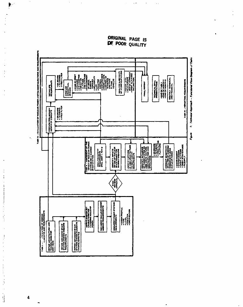
l Technical Approach-Functional Flow Diagram of Tasks 4
2 System Trade Table. I_OkWe at Space Stat,on 6
3 System Trade Table. 300 kWe at Space Station 6
6 28.50 Station & Tethered Platform Mission Power 9
5 Polar Platform Mission Power 9
6 Daily Mission Load Demand Curve I0
7 Space Station Mission Power Requirements 1I
8 Electroepitaxial Crystal Growth 12
9 Space-Produced Gallium Arsenide Market Projections I6
l0 Average Power Required for Gallium Arsenide Production 16
l I Chemical Vapor Transport Epitaxial Crystal Growth 13
12 Continuous Flow E lectrophoresis 16
I3 Estimated Electrophoresis Product Demand Ig
16 Estimated Space-Processed Optical Fiber Production Rate 20
I5 Estimated Power Requirement for Early Versions of MSL 23
16 Electrical Load Summary for Reference g-Person Station 25
t7 HousekeepingPower Requirements 25
18 Summary of Space Station Power Requirements 27
19 Nuclear Power System Benefits 28
20 Large Space Structures Assembly Operations 30
20a Orbiter Approaching Space Station 31
20b Orbiter Docked At Space Station 32
20c Large Assembly Under Construction 33
20d Array Shadowing From Large Structure 3#
2l Space Station Orbit Decay Time 35
22 Space Station System Elements 37
23 Near Term Cargo Payload Mass To Circular Orbital Altitude-
KSC Launch - Delivery Only 38
26 Basic Space Station Geometries 61
2_ Gravity Gradient Stabilized Space Station Concept #2
2(; Re(erence Space Station Mass and Dimensions 63
ix
1985027415-008
LIST OF FIGURES (Cont.)
FLmure Page
Number
27 Total Space Station Reference Data #3
28 Orbital Maneuvering Vehicle (OMV) 45
29 OMV LEO Performance 46
30 Orbital Transfer Vehicle (OTV) 48
31 GEO SOC Concept No. 2 #9
32 Polar Space Station Concept 50
33 Manned OMV Concept 51
3# Manned Orbital Transfer Vehicle 52
35 Advanced Launch Vehicle Projections (from NASA Space
Systems Technology Model, Volume II A, 3anuary, 198#) 53
36 Nuclear Safety Requirements Documents 58
37 300-Year Orbit Altitude 60
3g Radiation Exposure Limits for Humans 60
39 (Figure Number Not Used)
#0 Daily Dose To Blood Forming Organs 6I
#1 Electrical Power System Functional Diagram 65
#2 Effects of Plasma On Exposed High-Voltage Components 66
#3 Electrical Power Subsystem Candidates 67
44 Reactor Space Station Configuration Options 69
#5 Reactor Near Space Station C.G. ("Submarine" Concept) 71
#6 Reactor on Boom 72.
47 On-Board Reactor Options 73
#g Tethered Reactor 7# ,
#9 Tethered Reactor Characteristics 7#
50 Fluid Hose Tether 76
1 Tethered Tanker 76
52 Waveguide Tether 78
_3 Microwave Beam Tether "g
_# Tethered Reactor Options 79
_5 Free-Flyer Reactor gl
._6 Free-Flyer Reactor At'tributes gl
x
1985027415-009
LET OF FIGURES (Cont.)
Number
57 Co-OrbitingMicrowave Free-Flyer $2
5g Co-OrbitingTanker $2
59 Separation Distance Betweer, Space Station and Free-Flying
Power Source 83
60 High Orbit Free-Flyer Viewing Factor g5
61 Relative Free-Flyer Positio:. 85
62 Line-of-Sight Laser Free-Flyer Reactor 86
53 High Orbit Free-Flyer Tanker g6
64 Free-Flyer Reactor Options gg
65 Reactor-Space Station Configuration Selection g$
66 Summary of Potential Impacts on Missions g9
67 Shield Concepts 91
68 Reactor Subsystem Mass of Generic Reactor Types Versus
Thermal PcHer 92 "
69 Reactor Description 93
70 Power Conversion Systems Studied 95
71 Power Conversion Cycle Characteristics 96
72 Space Power System Characteristics 97
73 DividedShieldConcept forManned Applications 99
74 ShieldLayout - Four-PiIntegratedOn-Board System 100
7_ ShieldLayout - Four-PiReplaceableOn-Board System 10l
76 ShieldLayout - Four-PiShaped Shield 101
77 EffectofOutput Power and ReactorDistanceon Power
System Mass 102
7g Effect of Power Conversion Type on Power System Mass
With Four-Pi Shield 104
79 Comparison of Power System Mass for Various Power
ConversionTypes Witha ShapedFour-PiShield 104
80 Effect ofShield Geometry on Power System Mass 105
g I Boom-Mounted Configuration 106
g2 Characteristics ofSelected Power System Configurations 107
xt
1985027415-010

LLST OF FIGURES (Cont.)
F_-e Page
Number
g3 Tethered Configuration (Man Rated) 108
g4 Tethered Configuration (Instrument Rated) 110
g5 Characteristics of Selected Power System Configurations
Using Higher Power Stirring Engine Conversion 11t
g6 Startup and Shutdown Considerations for Boom and Tethered
Configurations 112
g7 Boom-Mounted Reactor System Elements 117
gg Tethered Reactor System Elements t 17
g9 Free Flyer Reactor System Elements 118
90 Net Reactor Electrical Power 119
91 Cylindrical One-Sided Radiator Size for I00kWe 12!
92 Two-Sided Flat Plate Radiator Size for 100kWe IZl
93 Fuel Cell Scaling Factors 123
94 Electrolyzer Scaling Parameters 123 .
95 System Mass versus Boom Length 124
96 MassStatement for l_0kWe Boom-Mounted Reactor
Configuration 126
97 STS Manifest Plan for Boom-Mounted Reactor System 127
9g Single Launch Weight Distribution 129
99 Single Launch Cargo Bay Manifest 129
I00 MassStatement for SingleSTS Launch of Reactor Systems I2g
101 Mass Statement for l_0kWe Te;hered Reactor Configuration 131
102 STS Manifest Plan for Tethered Reactor System 132
103 Free Flying Reactor Scenario Block Diagram 134
I04 Orbit Transfer Delta V _equirements as a Function ofOrbit
Plane DLfference and Reactor Altitude 136
lO._ Orbit Transfer Delta V Requirements as a Function of Time
Since Orbits Were Coplanar and Reactor Altitude 137
I06a Orbit Transfer Transfer Times With Phasing Orbit - Final
Orbit Altitude 600 Kilometers 13g
xtt
1985027415-011

¢,
LIST OF FIGURES (Cont.)
Figure Page
Number
106b Orbit Transfer Transfer Times With Phasing Orbit - ,:inal
Orbit Altitude 700 Kilometers 139
I06c Orbit Transfer Transfer Times With Phasing Orbit - Final
'Orbit Altitude 900 Kilometers 1_0
106d Orl)it Transf_.r Transfer Times With Phasing Orbit - Final
OrbitAltitude1200Kilometers I_I
I07 Transfer Orbit Delta V Recp_irements With Phasing Orbit I#2
108 Fuel Cell Scaling Factors 1¢4
I09 Mass and Volume Ratios of Gas, Supercritical and Liquid
Reactant Tanks Relative to Liquid Tanks I_
I I0 Reactant Liquifaction Process I_5
IIIa Projected1995RefrigeratorPerformanceSummary - 20OK l#7
I l Ib Projected 1995 Refrigerator Performance Summary - 50OK I#7
I I Ic Projected 1995 Refrigerator Performance Summary - 90OK Ill7
112 Reactant Liquifaction Power Requirements I #8
I 13 Low Temperature Radiator Characteristics 150
I-I_ Tanker Payload Mass 150
115 Free Flyer Reactor Power Flow Distribution I.¢I
lI6 Mass of I_0kW Free-FlyingReactor 152
117 Mass and Volume of Fuel CellSystem 153
l l g Makeup Fuel Requirements for Free-Flyer Tanker 1_
l19 Free-FlyerLogistics- InitialOperatingConditions I5#
120 Lifetime Logistics for Free-Flyer Reactor I56
121 Logistics for Five Free-Flyer Reactors 156
122 Unmanned Launch Vehicle- STS Derived 157
123 Alternative Propulsion Modes 156
12_ System Trade Table. 150 kWe atSpace Station 159
125 System Trade Table..300 kWe at Space Station I_9
12G Nuclear Electric System Requirements 162_i 63
127 NuclearSafety,-_equircmentsDocuments 165
xtil
i
1985027415-012

SUMMARY
A space stationwith a nuclearreactorsource of energy willbe designedandoperated differentfrom one with the energy converted from sunlight. Theobjectiveof thisstudy isto determinethe applicabilityof the SP-100 classofnuclearreactorelectricall_-,versystem to a manned space stationwl_ch isunderconsiderationby NASA. In the contracttechnic_ltasksthe missionswhich canutilizea nuclearelectricpower system are to be determined. Using typicalgenericconceptualdesignsofnuclearreactorpower systemsand spacestations,theassessmentwas made of the impact of the nuclearpower system on the mannedspace station arct,i_ure and operation. In turn, the effect of a manned spacestation on the n'Jclear reactor power system was determined.
The scope of the program included placing t_.e nuclear reactor and energyconversion equipment: (a) on the ration similar to a submarine installation, or on astructural beam a distance away from t,he manned activities and equipment; (b) ona flexible tether; or (c) on a free-flyer platform. To develop a size for use i,_ theanalyses, the electrical system power level was selected at 150 kWe and 300 kWe sothat several energy conversion methods would be examined.
As a result of the analysis it was found that the nuclear reactor power system=ould be placed in any of the three positions, but that at the system level thepenaltie.- were much greater in the case of the free-flyer than in the other two.The penalty was the large number of shuttle flights required to operate the _.oacestation and place the nuclear electrical power system in orbit. In turn, the react,_rshield weight was low and the reactor could be operated in a long-lived orbit. Witha reactor on the space station or on a flexible tether, the system could beimplemented and operated with few shuttle flights.
It was _ound that as the space station power level grew into the multl-hundredkilowatt range and the area of solar arrays increased accordingly, that thearchitecture of the space station was affected. The nuclear reactor power systemthen became an attractive alternate energy source since it did not require solarorientation and it was immune to shadowing by the spacecraft appendages orstructures.
I
1985027415-013
i •I!
4
11.0 INTRODUCTION
I
1II 1.1 Program Backgro_d
i! The SP-100 program was initiatedin 1983 to establishperformance limitsand
i advance technologyfor 100-kW classof spacenuclearpower systemsin supportofi militaryand civilianmissions. The firstphase of the SP-100 program is the
1 development of rationale for a reactor electrical power system, technology) assessment, and conceptual designs of reactor powered conversion subsystems.i Identificationof militaryand civilianmissionrequirementsfor100-kW classspace
:t nuclear power systems, identi£ication of system concepts that can meet theset mission requirements, and resolution of the technological feasibility issuesij associated with the concept development are the goals of the effort. A
determination of the costs and schedule required to proceed with development isi also to be made. These activities are proceeding toward a recommendation in mid-) 1985 as to whether to proceed to the next phase, which would be the design,
manufacture, and testing of a developmental ground engineering system.
Potential missions that might benefit from space nuclear reactors fall in fourmajor areas" military missions, Flanetary missions) manned space station missions,and civilian/commercial missions. This report identifies potential manned spacestation non-military missions that would benefit from a space nuclear reactor andanalyzes nuclear reactor-powered electrical system configurations to accomplishthese missions.
1.2 Scope of Work
Current NASA plans for manned space station missions were reviewed to assesstheapplicability, benefits, and constraints of t00-kWe class of nuclear reactors insupplying space station electrical Power. Power requirements were summarizedfrom the NASA Mission Requirements Working Group reports (ref. 1) to determinebasic mission needs. Other loads we<e also examined, including space stationhousekeeping requirements and various space station growth scenarios. Thealternative growth scenarios considered missions that might be enabled by theavailability of sufficient power at the space station. These loads are not currently
' in the reference mission set, and power demand growth might result fromaggressive commercial involvement in the space station program.
Additional mission factors that might affect the use of nuclear Power we4ereviewed qualitatively. These factors include atmospheric drag, space stationattitude control and flexibility, spacecraft traffic management) and environmentalinteractions. Power growth scaleability w_ also considered. Although thiscontract did not include a tradeoff between solar-powered and nuclear reactor-powered electrical systems, such an analysis was conducted at NASA LeRC.
Safety requirements were reviewed tha. may apply to space nuclear reactors, ingeneral, and to reactors on or near a manned space station) in particular. Existing
: requirements were reviewed for their applicability to this system and forconsistency. The impacts of safety requirements on a manned space station and itsmissions were assessedand additional safety requirements were identified.
Fourteen different system configurations were considered for the nuclear reactorpower system and space station combination. These configurations fell into threegeneral classes: on-board nuclear reactor power systems, tethered nuclear reactor
2
)
1985027415-014

power systems,and free-flying nuclear reactor power systems. Power transmissionby electromagnetic beaming, by conduction, and by fluid transfer was considered.A general screening of these configurations was madeto reduce the numberto onecandidate from each configuration class. This selection was made on the basis ofrequired nuclear reactor power system sizes, traffic constraints, heat removal, andspace station/mission impact.
h conceptual desigr of each of the three candidate configurations was performedto provide quantitative data for a trade study. The trade study compared the threedesignson the basis of initial and life-cycle mass and volume in orbit, Space
" Transportation System logistics, nuclear safety, and orbit mechanics. Spacestation power levels of IS0 kWe and 300 kWe were evaluated. The space stationarchitecture, orbit, and size considered was a generic design which isrepresentative of what might satisfy missior_requirements currently plannedin themid to late t590's. A generic reactor design was usedwhich is close to one optioncurrently being developed elsewhere in the SP-100 program. Several powerconversion options were considered, including thermoelectric, thermionic, andthree different dynamic cycles (Bray_on, Rankine, Stirling). Radiation shieldvariations treated included four pi, shaped four pi, two pi, and conical (shadow)shields.
Requirements imposed on the nuclear power system due to operation with themannedspace station in a low-earth orbit and requirements imposedon the space
' station and on elements of the Space Transportation Systemdue to the nuclearelectric powersystemwere defined.
1.2.1 Contract Statement of Work
The statement of work of the contract is shownin flow diagram form in Figure 1.Essentially_ the program dealt with three technical tasks and one task toencompassreporting and presentations. The task titles identify the work. Theseare=
o Task l: Identify manned missionsthat would materially benefit and/or beenabled through the use of nuclear power_ and their respective powerrequirements.
o Task ll= Assessthe impact of the presence of a nuclear electric powersystem (NEPS) on the architecture of the Space Station with particularemphasisonsafety.
o Task Ill= Prepare three conceptual designsof a NEPS, including on-board9tethered, andfree-flyer approaches.
o TaskIV= Documentthe studyin a final report.
1.3 ConfiKurations Selected
The trade studieswere performed for three systemconfigurations:boom-mountednuclear reactor power systemwith electrical transmissionlines_tethered nuclearreactor power systemwith an electrolysisplant whichpumpsgaseoushydrogenandoxygenthrough hosesto fuel cells on the spacestation_ and a free-flying nuclearreactor power systemwith an electrolyzer and liquefier, and transfer of fuel cellreactants with a space-basedorbital transfer vehicle. Two power levels weretreated: 1_0kWewith thermoelectric conversion,and300kWe with a Stirling cycle
3
1985027415-015
_r
I
1985027415-016

heat engine. The loads are space station loads, not generated power levels. Theboom-mounted nuclear reactor power system was rated at I_3 kWe to compensatefor transmission losses and used a shaped four pi shield at the reactor. Thetethered nuclear reactor power system was rated at 20g kWe to compensate forelectrolysis and fuel cell inefficiencies. A man-rated four pi shield and aninstrument-rated conical shield were treated for the tethered reactor. The free-flying reactor required two reactors on the same spacecraft to avoid burnuplimitations with the thermoelectric system for the 150 kWe power level. Thesetandem reactors were each rated at }60 kWe and used one conical (shadow) shield.Although the Stirling cycle conversion could also be considered for the 150 kWeload, the two conversion systems were kept separate so as to evaluate the twoconcepts. For a 300 kWe load, a single large reactor with a Stirling cycleconversion was evaluated to determine the system parameters.
1._ Trade Study Parameters
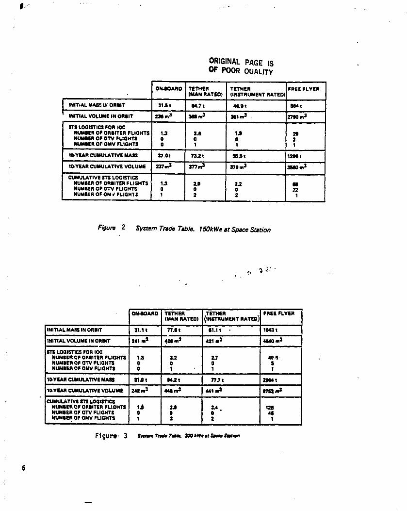
The mass and volume in orbit were determined for each configuration, both forinitial operation and for total life cycle operation. Space Transportation System(STS) logistics were then compared. The results are summarized in Figure 2 for150 kWe and in Figure 3 for 300 kWe at the space station.
From Figures 2 and 3 we see that the boom-mounted nuclear reactor power system "requires the fewest shuttle flights for initial operation and essentially no makeuppropellant over the ten year lifetime. The boom-mounted and tethered nuclearreactor power systems both require some active f_rm of propulsion to boost thereactor to a long-lived orbit at the end of its useful life, which the free-flyer does
not, since it can be operating at any selected altitude. Operating the reactor onlyin a long-lived orbit, however, requires a large number of shuttle flights to placethe initial water/fuel charge in orbit, and even more flights to provide OTVpropellant, as well as 22 OTV flights (round trip) for fuel transfer over the ten yearlifetime.
[I From the analysis it was determined that the boom-mounted power system is the
optimum for minimum logistics - orbiter flights and total mass in orbit in tenyears. If the radiator can be detached_ the remainder of the reactor power systemwith a long tether will, when severed, remain in a 300 year orbit without asupplemental boost.
1._ General Condusions
The mission requirements and sensitivity analyses performed for this study indicate 'that a space nuclear reactor power system is a viable candidate for manned spacestations with high power needs. Although no single space station mission wasidentified which favors nuclear power specificallyp mission power requirements ofat least 1_0 kWe or more have been projected for the space station. In this powerrange, the design of a space station with a solar photovoltaic electrical powersystem becomes difficult because of the large area of the array and the exclusionvolume the array creates because of rotation. These difficulties relate to stationdynamics, orientation flexibility, traffic management, energy storage anddistribution. Environmental effects involve corona and voltage breakdown due tothe ionospheric plasma, and contamination and debris from the space station andvehicular traffic. Other solar power systems with higher efficiency conversionsystems may move the point at which nuclear power is used for prime space stationpower. The atmospheric drag of the reactor-powered systems is extremely low
5
1985027415-017
ORIGINAL PAGE ISOF POOR OUALITY
• ii
ON-BOARD TETHER TETHER FREE FLYER(MAN RATED) (INSTRUMENT RATEDI
: • Jl . i i
INIT;AL MA,I_ I_ ORBIT 31 3 t B4,7 t 48.9 t _ t
INITIAL VOLUME IN ORBIT 23l n,J _ m3 381 m3 27110m3: ,| •
Ili LOGISTICS FOR IO¢NUMBER OF ORBITER FLIGHTS 1,3 2.l 1J 211NUMBER OF OTV FLIGHTS O 0 0 2NUMBER OF OMV FLIGHTS 0 I 1 1
• i i | i i
1B-YEAR CUMULATIVE MASS 32.0t 73.2 t _3 t 121NIt: I, i m
10-YEAR CUMULATIVE VOLUME 237m 3 377m 3 370 m3 3$60 m3
" CUMULATIVE STS LOGISTICS 'NUMBER OF ORBITER FLIGHTS 1.3 2.9 2.2 libNUMBER OF OTV FLIGHTS 0 0 0 22NUMBER OF OM_/FLIGHIS 1 2 2 1
Figure 2 SystemTradeTJble. 150kWeat SpaceStation
I
ON,.IOARO TETHER TETHER "" RATEO'--) FREE, FLYER(MAN RATEDI (INSTRUMENTi L I I
INITIAL MASS IN ORBIT 31.1 t ?'/.8 t 11.1 t 1043 t
INITIAL VOLUME IN ORBIT 241 "m3 _ m3 421 m3 444Q m3,. ,,- ,m.. , i
ors LQGI_'rlC$ FOR IO¢NUMBER OF ORBITER FLIGHTE 1 3 3.2 2.7 4B-S. "NUMBER OF OW FLIGHTS 0 O 0 1NUMBER OF OMV FLIGHTS O I 1 1
ill ii i ii H|
10-Yf, AR CUMULATIVE _ 31.11t N2 t 17.7 t 2_1B4ti ii . H:I
IO.YUR UULATIVE VOLUME 242 m "1 4441m3 441 w 1 _ m3B, i • |m i H iJ
CUMULATIVE _ LOQISTI(:$
NUMBER OF ORBITER FLIGHTS 1JI 3.8 3.4 • 12BNUMBER OF OW FLIGHTS 0 0 O &lNUMBEA OF OMV FLIGHTS 1 2 | 1
; i ,. I wl
Ftgure. 3 sin,,,,,TamT-'.*L,lm,w,,rr_msur_o,,
6
1985027415-018

when compared with solar-powered alternatives even at the 270 nmi altitudeproposed for the space station. In addition, nuclear reactor power system radiatorscan be oriented into the orbit plane. The compactness of the nuclear reactorsystem also facilitates assembly of large space structures) by providingaccessibility in essentially all directions and because the reactor is insensitive toshadowing by the large structures.
The trade studies showed that the cost of restricting reactor operation to a higherorbit than the space station for maintaining a 300 year decay life is many shuttleflights and many orbital transfer vehicle flights, The boom-mounted nuclearreactor power system) on the other hand, requires orgy one and a fraction ofanother shuttle flight for all power subsystemsplus space station drag makeup overthe entire reactor lifetime. The tethered reactor requires two to three shuttleflights. An orbital boost system is necessary for the boom-mounted and tetherednuclear reactor power systems for end-of-life disposal of the reactor.
Comparison of the various concepts for transferring power from the reactor to thespace station revealed that the combination of electrolysis and fuel ceils is anattractive option. This combination) which is essentially a separated regenerativefuel cell (RFC) system) usesreactor electrical power to electrolyze water into itsconstituents which are transported to fuel cells on the space station to berecombined and returned to the reactor as water. The RFC appears to be muchmore efficient than either microwave or laser power transmission. This system isalso attractive because of its synergism with space station life support andpropulsion systems because of its use of hydrogen) oxygen) and water. Since thefuel cell reactants and water are easily storable) this also allows the reactor tooperate in a base load mode) producing a steady rate of reactants at constantpower even while the space station power demand fluctuates. Additionally) formake-up fuel due to leakage and use in other systems) the main source) water) isall that is required. This can be brought up when required and presents no hazardduring transportation and storage.
1985027415-019

2.0 SPACE STATION MISSION REQUIREMENTS
Space station missions that may benefit from the use of a nuclear reactor powersource are the power-intensive materials processing missions and those that requirebroad accessibility over l_:ge volumes. With the Mission Requirements WorkingGroup, NASA maintains a current file of space station mission requirements forplanning purposes (ref. l). The most recently compiled summary projects anaverage power requirement for 75 kWe at I.O.C. and 150-200 kWe in the mid tolate 1990's. Peaking needs and space station housekeeping may raise this need to150 kWe to perform the missions in the MRWG data set. Additional missions madefeasible by the availability of sufficient space station power, or by robustcommercial demands, might lead to a requirement for 300-500 kWe in the 21stcentury. Large space structures assembly missions would benefit from a powersource which allows greater accessibility and is less sensitive to traffic, dr_g, andsolar shadowing than large solar arrays.
2.1 Electrical Power Nee<b
2.1.1 Reference Space Station Mission Set
NASA's Space Station Task Force has compiled a reference file of space stationmission descriptions. This reference file was originally estab'.ished as a validatedsummary of missions identified by the eight NASA contractors of the Space StationNeeds, Attributes, and Architectural Options Study during fiscal year 1983 (ref. 3).The Mission Requirements Working Group (MRWG) reviewed all the contractormission descriptions in May 19gJ to establish a single planning document (ref. [).This document represents NASA's reference mission set for space stationdevelopment and planning activities. The MRWG now meets regularly to reviewand update the Space Station Mission Requirements Report and release thissummary report on a monthly basis.
The complete set of missions considered by the MRWG includes candidate missionsin three categories: Science and Applications Commercial Utilization, andTechnology Development. These categories are each summarized by a disciplinepanel which interfaces with its respective user community to analyze and assemblepotential missions which could be supported by a space station system. Dataincluded in the monthly Space Station Mission Requirements Report are briefmission descriptions; time phasing; allocation of resources such as power, datatransmission rate, crew time, volume, and transportation requirements; an_!integrated resource requirements.
The complete space station system includes more than just a single, mannedfacility: it includes a manned facility, free-flying platforms in various orbits,service vehicles, orbital maneuvering vehicles) and launch and resupply vehicles ofthe Space Transportation System. The current reference mission set for the I990's
I considers a single space station in lo'N-inclination) low-earth orbit as its onlyi permanently manned facility. Other facilities that may occasionally be visited by
mr _ include platforms in low altitude polar orbit and in geosynchronousorbit.
The average e, ectric power requirements of all the reference payloads in the spacestation mission set are shown in Figures t) and 5. The average payload powerrequirements in the low inclination, manned space station begin with 55 kWe in1991 and grow steadily to 112 kWe by 1996. The maximum power in the currentrelerence mission set is 123 kWe in 1999. These power requirements are for the
1
I 8;I
1985027415-020

ORIGINALPAGE IS
KILOWATTS OF POOR QUALITY140
120
100
8O
4O
Ira:2O
0'91 '92 '93 '94 '95 `96 `97 `98 "99 I)0
CALENDAR YEAR
Figure 4 28.5 ° Station & Platfolm Mission Power
KILOWATTS16 ......
" _ _ 'iI i!;ii__:___''i _4 _
iiii I = • .
`91 `92 '93 *94 `95 `96 `97 '98 '99 I)0
CALENDAR YEARS
Figure 5 Polar Platform Mission Power
1985027415-021
reference missions and describe payload requirements only on the manned spacestation. They do not include housekeeping loads, nor do they include the powerrequirements for space transportation.
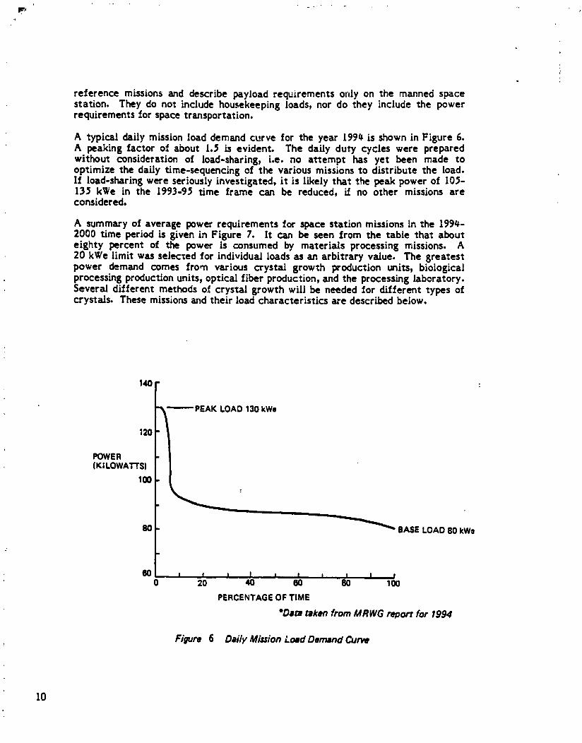
A typical daily mission load demand curve for the year I99_ is shown in Figure 6.A peaking factor of about 1.5 is evident. The daily duty cycles were preparedwithout consideration of load-sharing, i.e. no attempt has yet been made tooptimize the daily time-sequencing of the various missions to distribute the load.If load-sharing were seriously investigated, it is likely that the peak power of [05-135 kWe in the 1993-95 time frame can be reduced, if no other missions areconsidered.
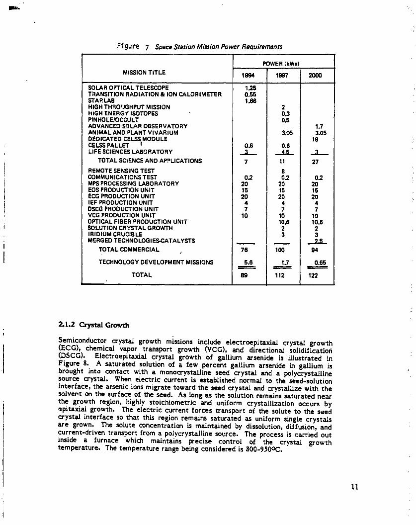
A summary of average power requirements for space station missions in the 199_-2000 time period is given in Figure 7. It can be seen from the table that abouteighty percent of the power is consumed by materials processing missions. A20 kWe limit was selected for individual loads as an arbitrary value. The greatestpower demand comes from various crystal growth production units, biologicalprocessing production units, optical fiber production, and the processing laboratory.Several different methods of crystal growth will be needed for different types ofcrystals. These missionsand their load characteristics are described below.
PEAKLOAD130kWe
120P !
POWER(KILOWATI'S)
100
BO BASE LOAD 80 kWe
60 t , = I l, I I I I I0 - 20 40 60 80 100
PERCENTAGEOFTIME
"Data _ken from MRWG report for 1994
Figure 6 Deily Mission LoRdDemand Curve
10
1985027415-022
Ftgure 7 SpaceStation Mission Power Requirements
POWER ,kWe)
MISSION TITLE 1994 1997 20(]0
SOLAR OPTICAL TELESCOP'E 1.25 'TRANSITION RADIATION & ION CALORIMETER 0.55STARLAB 1.66HIGH THROUGHPUT MISSION 2H_GH ENERGY ISOTOPES 0.3PINHOLE/OCCULT 0.5ADVANCED SOLAR OBSERVATORY 1.7ANIMAL AND PLANT VIVARIUM 3.05 3.05DEDICATED CELSS MODULE 19CELSS PALLET Ir 0.6 0.6LIFE SCIENCES LABORATORY 3 4-6 :3
TOTAL SCIENCE AND APPLICATIONS 7 11 27
REMOTE SENSING TEST 8COMMUNICATIONS TEST 0.2 0.2 0.2 ,MPS PROCESSING LABORATORY 20 20 20EOS PRODUCTION UNIT 15 15 15ECG PRODUCTION UNIT 20 20 20IEF PRODUCTION UNIT 4 4 4DSCG PRODUCTION UNIT 7 7 7VCG PRODUCTION UNIT 10 10 10
: OPTICAL FIBER PRODUCTION UNIT 10.6 10.6! SOLUTION CRYSTAL GROWTH 2 2
IRIDIUM CRUCIBLE 3 3
i MERGED TECHNOLOGIES-CATALYSTS .._
| TOTAL COMMERCIAL , 76 100 94I' TECHNOLOGY DEVELOPMENT MISSIONS 5.6 1.7 0.65
TOTA L 89 112 122
2.1.2 Crystal Growth!
Semiconductor crystal growth missions include electroepitaxial crystal growth(ECG), chemical vapor transport growth (VCG), and directional solidificatioh(DSCG). Electroepitaxialcrystalgrowth of gallium arsenideis illustratedinFigure g. A saturated solution of a few percent gallium arsenide in gadlium isbrought into contact with a monocrystaJline seed crystad and a polycrystaL[llnesource crystnl. When electric current is established normal to the seed-solutioninterface, the arsenic ions migrate toward the seed crystad and crystallize with thesolvent on the surface of the seed. As long as the solution remains saturated nearthe growth region, highly stoichiometric and uniform crystallization occurs by-.pitaxial growth. The electric current forces transport of the solute to the seedcrystal interface so that this region remains saturated as uniform single crystals
i are grown. The solute concentration is ma/ntained by dissolution, diffusion, andcurrent-driven transport from a poiycrystalline source. The process is carried outII inside a furnace which maintains precise control of the crystal growth
temperature. The temperature range being considered is 800-9_0oc.
11
1985027415-023

ORIGINAL PAGE ISOF POOR QUALITY
ELECTRODE . __ _"
POLYCRYSTALLINE [ • ISOTHERMAL{800-950°C)Gs/_tSOURCE . • ELECTRICCURRENTORWES
BORONNITRIDE .,_ ] Asto seed(j,, 10-50 AJonn)INSULATOR _ .:. ." t._ •SOLUTIONREPLENISHEDBY
r SOURCE
GALLIUMSOLUTION • --'? I ..... 1• " • ZEROGELIMINATESBUOYANT
FURNACE"-- - CONVECTIONCAUSEDBYOHMICHEATING
SINGLECRYSTAL __
GIASSEED
ELECTRODE - .--
Figure 8 Eleccroepitaxial Crystal Growth
The electric current densities required for current-controlled electropitaxiaJgrowth are in excess of l0 A/cm 2. This current flows through the melt and thecrystal. Resistive heating and Peltier cooling at the interface cause temperaturegradients in the melt. In a gravitational field these temperature gradients wouldcause therma_ convection, which would destroy the uniformity of the crystal. :Thermal convection does not occur under microgravity conditions. Therefore highcurrent densities are a_Jowed in the microgravity environment of space and, sincegrowth rate is linearly proportional to current density, rapid growth of large,uniform, compound semiconductor crystals is allowed.
Microgravity Research Associates, Inc. is developing the electroepitaxiaI growthprocess for space-based growth of gallium arsenide (GaAs) crystals. GaAs is asuperior semiconductor to silicon in several areas. It has a much higher switchingspeed, lower power requirement, lower heat loss, and higher temperatureresistance. Art o! these advantages combine to aUow gallium arsenide to have ahighercircuit element density with greatlyenhanced processingspeeds and reducedcooling requirements. Furthermore, GaAs is much more resistant to radiation thanis siJicon, aJJowing itsuse in nuclear, space, and military environments wheresilicon-based semiconductors would quickly degrade. Finally, GaAs emits coherentlight, which aJlowsits use in optical processing equipment.
Ground-based GaAs growth experiments have been performed with low currentdensities and small dimensions to suppress thermal convection, but realexperimental verification of the concept must await spaceflight. MicrogravityResearch Associates has a 3oint Endeavor Agreement with NASA to develop theelectroepitaxia_ growth processfor gcttium arsenide.
The electrical power required for electroepitaxial growth o£ gallium arsenidedepends on both temperature and thickness of the crystal At g7_C furnacetemperature, the energy required to grow I cm thick GaAs crystals in five days is
12
1985027415-024
aboat 66 kWh/kg. In addition to the power required for the growth current, anadditional power of 40 kWh/kg is requi:ed to maintain the furnace temperature forfive days. The power load is then 66 kWh/kg of uninterruptible DC electric powerat 28 VDC, plus 40 kWh/kg of interruptibte power Ioc additional heating.
The estimated market demand for space produced gallium zxsenide is sho_n inFigure 9 (ref. 4). These projections assumed market prices that ref;ect decreasing
,. production costs resulting from the following flight scenario= in 1990, crystals aregrown in the orbiter on six day missions; in 199i, crystals are grown on a free-flying platform which is serviced by the orbiter; in 1992-93, crystals are grown indedicated modules attached to the space station; beyond 1993, crystals are grownin free-flying platforms serviced from the space station. The average powerrequired to satisfy these de,-r,and projections is shown in Figure 10. In the mid-1990's, the power required for electroepitaxiaJ growth of gallium arsenide is likelyto be in the range of 10-30 kWe. By the year 2000, this value is expected to rise toas I_gh as 100 kWe. In the MRWG reference set, a ground rule was observed wl_*.hlimited the space station-supplied power for any single commercial mission to20 kWe. For this study we did not observe the 20 kWe limit. It is implicit in thisassumption that commercial space station users requiring more power would eitherprovide their own power source on the space station or would move their processingsystem to a free-flying platform.
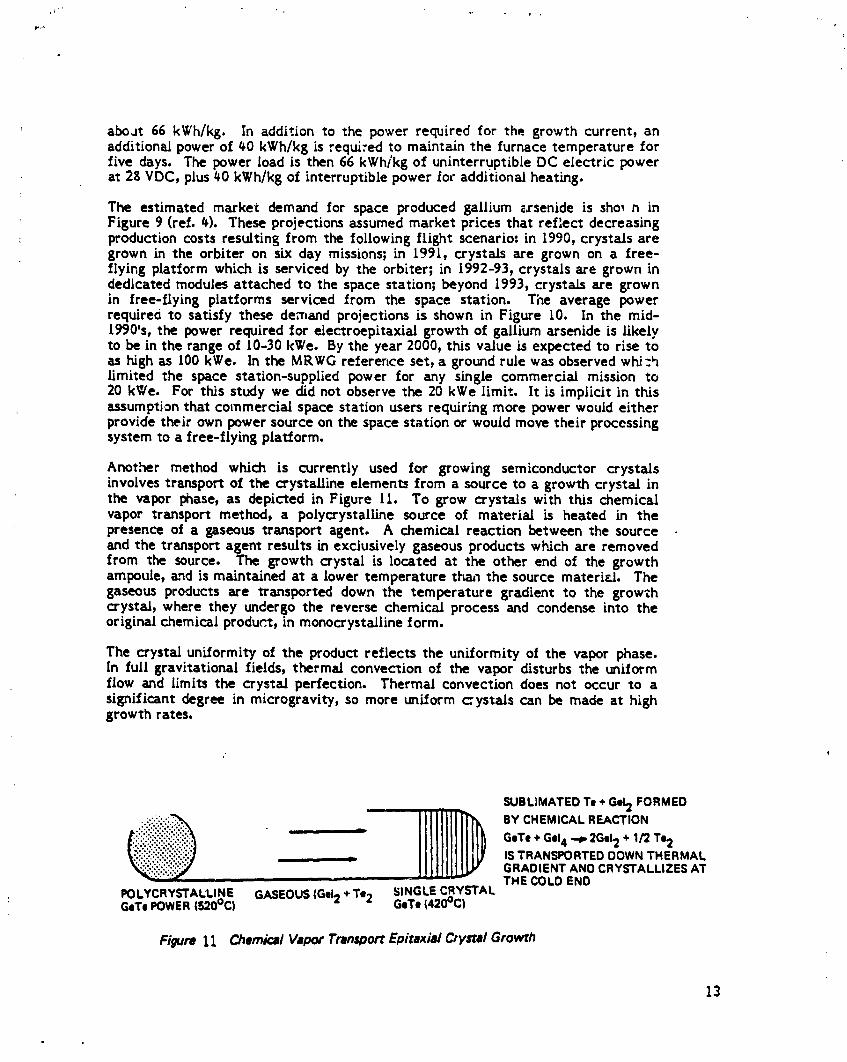
Anot,her method which is currently used for growing semiconductor crystalsinvolves transport of the crystaUine elements from a source to a growth crystal inthe vapor phase, as depicted in Figure II. To grow crystals with tl_s chemicalvapor transport method, a polycrystaUine source of materia_ is heated in thepresence of a gaseous transport agent. A chemical reaction between the sourceand the transport agent results in exclusively gaseous products which axe removedfrom the source. The growth crystal is located at the other end of the growthampoule, aLndis maintained at a lower temperature thzu_the source materi_. Thegaseous products are transported down the temperature gradient to the growthcrystal, where they undergo the reverse chemical process and condense into theoriginal chemical produ_.t, in monocrystalline form.
The crystal uniformity of the product reflects the uniformity of the vcpor phase.[n full gravitational fields, thermal convection of the vapor disturbs the uniformflow and limits the crystal perfection. Thermal convection does not occur to asignificant degree in microgravity, so more uniform cystals can be made at highgrowth rates.
SUBLIMATEDTe �G_FORMED
GeTe+ Gel4 --p 2Gel2 + 1/2Te2,, ISTRANSPORTEDDOWNTHERMAL
GRADIENTANDCRYSTALLIZESAT- THECOLDEND
, POLYCRYSTALLINE GASEOUS(Gel2 +Te2 SINGLECRYSTALGeTePOWER(520°C) GeTe(420°C)
Figure 11 Chemical Vapor Tran_oort Epitaxia/ Crystal Growth
13
1985027415-025

8
7
6-
S
ANNUALMARKET HIGHDEMAND 4
•(TONNES)
3
2
I
.: t
1990 91 92 03 r.-, 95 96 07 98 99 20GOYEAR
Figure •9 $1_ce.Produced Gallium Arsenide Market Projections
lOG
8O
6OAVERAGEPOWERREQUIREMENTS HIGH(kW)
40 MEDIUM
LOW
20
199" 91 92 93 94 95 96 97 98 99 2000YEAR
14 Figure 10 Average Power Required for Gellium Anenide Production
1985027415-026

Thisprocessisbeingdevelopedat RensselaerPolytechnicInstitutefor growth oflarge,monocrystalline,compound semiconductors.Previousexperimentshave beenperformedwithgermanium and groupVI compounds (ref.5). Futureplanscallforvapor phase growth of large, ternary semiconducting compounds, such asHgxCdl-xTe. These couldbe usedas infrareddetectors,witha responsefunctionwhichcan be selcctedby choosingx.
A seriesofcrystalvaporgrowthexperimentsare scheduledon theMEA-A facilityaboardthe orbiter.The firstflightwas on 5TS-& The crystalmaterialon thisflightwas germanium-selenium.Allsubsequentflights,beginninginAugust 198#,are91armedwithmercury-cadmium-teiluride.
Directional solidificationcrystal growth techniques can be applied tosemiconductorsor metals.Ingeneral,thematerialtobe crystallizedismelted in acruciblewithina furnace. The furnaceis designedwith a temperatureprofilewhich encompasses temperatures above and below the melting point. Crystalgrowth occurs at the cooler end of the crucible. The crucible is either stationaryor it is slowly pulled out of the furnace_ down the thermal gradient. In eitherconfiguration, crystal growth proceeds as a result of heat transfer from the melt.
A steady power of I0 kWe has been assumed for chemical vapor transportp-oduction in the mid 19901s, and 7 kWe for directional solidification. This power isrequired primarily as heat. It can, in general, be interrupted for periods on theorder of minutes. It can be either DC, or AC at any frequency.
• -1.3 Biological Matermls Processing
The usefulness of a wide range of biological materials depends on the degree towhich they can be concentrated and purified, Current processes for separatingthese materials are often limited by convection. The materials are purified byflow processes in aqueous solution. The sharpness of the flow patterns is degradedby thermal and buoyancy-driveu convective forces. This lack of resolution limitsthe purity of the separation products. Elimination of convective forces can greatlyenhance the sharpness with which different materials can be separated, as well asincreasing the concentration of the product. The improved separation ofpharmaceuticals that can be achieved in space o fers a near-term commercialproduct of space-based materials processing. Two processes have been consideredfor this application," continuous flow electrophoresis and isoelectric focusing.
_iological materials, such as proteins, enzymes, and cells often have a surfaceelectric charge distributior, which causes them to respond to an electric field.When placed in a fluid medium with an electric potential dilference between twoends; these materials will be transported toward one end. The speed with whichthe materials travels varies according to the charge distribution. Dilferentmaterials have different mobilities. This difference in mobility allows differentmaterials to be separated according to their electric charge distribution.
Figure 12 shows conceptually how a continuous flow electrophoresis apparatusworks. A liquid buffer solution is located between two electrodes. A potentialdifference between the electrodes establishes an electric field in the solution.
Those components of the material to be separated which have the highest electricmobility move the fastest to one eh.'ctrode. After some time in the field, thevarious components of the material are separated. On Earth, buoyancy-drivenconvection caused by concentration differences and by density changes due to
15
1985027415-027

-_ OUTLET PORTS
F" -)
: _ CATHODE
ANODE
,I ELECTRICFIELD
BUFFERSOLUTION
, Figure 12 Continuous Flow Elecrrophoresis
3oule heating limits the size of the sample which can be separated. Typically,samples of less than 0.l ml are separated on a porous gel plate by a batch processwhere the samples are frozen into place after some period in the chamber. Thesmall size of the apparatus limits the separation resolution, while convectionconsiderations limit the possible purity of the product.
Elimination of gravity-driven convection in space allows a continuous flowelectrophoresis process (CFE) in which the buffer solution flows continuallyperpendicular to the electric field, while the sample is also added f-ont/nuously tothe processing chamber. Much larger volumes of sample material can be separatedin this manner with much larger processing chambers. As shown in the figure, theproduct materials are collected in distinct collection vials. The continuousprocessing, larger volume, longer time in the electric field, and lack of convectionallows much higher materilds throughou% higher yie:d from a given quantity ofsample material, finer separations, and higher purity of product material than canbe _chieved on Earth.
16
1985027415-028

A similar technique which has been proposed for space-based separation ofbio|ogical materials is isoelectric focusing. The buffer solution establishes a pHgradient when the electric field is imposed. Since the mobility of the material tobe separated varies as the pH of the buffer9 the sample material moves _n thedirection of the gradient to a particular value of the pH" the isoelectric point.The products are well-focused within the pH gradient and then collected as incontinuous flow e,ectrophoresis. This method may have potential for even finerresolution than electrophoresis, but has not yet been demonstrated in space. Sincet_ pH environment of isoelectric focusing is extreme, it is not suitable forprocessing of living cells. Three experiments are scheduled for hormone
) purification in the orbiter mid-deck in Igg#.
The requirements for space station accommodation of biological separations| processes are generally less than for semiconductor growth, especially since the
temperatures are very low. Power requirements especially are eased. The needl for refrigeration to preserve samples imposes special thermal control constraints.
The continuous flow electrophoresis process is currently the most advanced MP$program. The first successful results were obtained in the Apollo-Soyuzspacecraft. In this experiment, in which material was separated by a batch processin a small column and frozen in place, the degree of separation of human fetalkidney cells was higher than any previous results. As a result, distinctions wereidentified between three different cell types :hat had not previously beenidentified. The successof the Apollo-Soyuz experiment, an extensive ground-basedresearch program, and especially the ST5-_ mission has resulted in optimism thatthe concept is understo_xl well enough to do engineering design. McDonnell-Douglas Astronautics and Ortho Pharmaceuticals Division of 3ohnson and 3ohnsonhave a 3oint Endeavor Agreement with NASA (r=.f. 6). The developers now plan tofly a production prototype electrophoresis unit in IggS) which will produce the firstcommercial product. The development program apparently calls for a fleet ofunma.aned, shuttle-tended free-flyers beginning in [986. Although specific plansare proprietary) it seems reasonable to project attaching these automated factoriesto a space station when one becomes available. This would allow the use of spacestation power and control systems, as well as facilitating materials storage)delivery, and retrieval by operating through a single central base. Present plann._n8are for CFE5 III electrophoresis experiment to go on shuttle flight #I-D (to belaunched in 198#) attended by Mrs. C. Walker (of McDonnell Douglas Co.) in space.
A large number of biological products has been proposed for space stationseparation. A recent forecast of the potential for space-produced pharmaceuticalsindicated the numbers of patients could be helped annually) shown in Figure 13 .'-(ref. 7). *
The power required to process suff;.cient material by electrophoresis to satisfy thisdemand in the mid-1990's has been estimated to be 15kWe. isoelectric focussing of
J additional materials is assumed to add another #kWe. This power is primarily thatrequired to maintain the electric field in the apparatus) wl_ch must be DC power.
: Other power consumers are for refrigeration of the biological materials and forfluid pumping. These usesare likely to be for AC power.
17
1985027415-029

FIGURE t3: ESTIMATED ELECTROPHORESIS PRODUCT DEMAND
Bioproduct Annual Patient Load
Pancreatic beta cells 3.2 millionEpidermal growth factor 1.1 millionHuman growth hormone 0.g5millionAntitrypsin 0.5millionInterferon 20 million
4 7-1.# Glasses and Fibers
i The reduced gravity in orbit allows materials to be processed in a container-free, environment. Fluids in microgravity conditions form large globules that "float" in
space without spilling or breaking up. This allows the possibility of melting andi resolidifying materials without the materials ever contacting the container walls
' while in the molten state. This property might be useful for a variety of materialclasses, the most hopeful class being high quality and unique glasses.
There are two features of glass processing that make the containerless processing. available in microgravity especially attractive. First, the high melting points of :
most glasses make them extremely reactive in the molten state. The chemicalreactivity causes molten glass to interact with the container walls, resulting inimpurity introduction into the melt. In gravitational processing, these impuritiesare unavoidable. Since the optical and mechanical properties of glass are verysensitive to impurity levels, chemical reaction with the crucible often seriouslydegrades the glass quality. Containerless processing should eliminate impuritygeneration by this mechanism and allow more perfect optical properties andstronger glasses.
Second, glasses are distinguished from metals and other solids by their lack ofcrystalline structure. Under gravitational conditions, molten glass as it cools tendsto solidify around nucleation sites at the crucible walls, because the walls arecooler than the interior of the melt and the impurity level is higher there, Crystalstend to grow around these nucleation sites, resulting in a higher degree ofcrystalline structure than is desirable. In a containerless environment, a higherdegree of supercooling is possible without the onset of heterogeneous nucleation_thus allowing a lower level of crystalline structure and therefore more ideal glassyproperties. Homogeneous nucleation also allows the processing of glasses withdifferent chemical mixes than are possible on earth. So contalnerless processing
: allows more ideal glassy properties and should allow unique glasses to form whichcannot be duplicated on earth.
A facility for processing glass in space will be dominated by the furnace. Thefurnace has two primary functions: a programmable power supply for heating and apositioning control system for holding the melt in place. The material samplewould likely be heated by absorption of some sort of electromagnetic radiation:
18
i
1985027415-030

most likely in the microwave or infrared frequency range. Other heatingmechanisms that have been proposed include electron beam impingement and solarconcentrators. Although the melting temperature of most of the candidate glassesis very high, the actual heating power load can be quite low because contalnerlessprocessing eliminates conductive and convective hea*. losses. A kilogram sizedspecimen of silica glass can be melted in a half hour with about a I kW heatingsource. Heat losses can be further minimized by using infrared reflecting walls. Aglass specimen would be heated to a few d-_grees superheat and then rapidly cooledto promote ,homogeneousnucleation.
The heated samples tend to drift in space due to orbital dynamics and g jitter ifthey are not actively held in place. They can be positioned by several means. Theycan be attached to a sting which holds them in place by surface tension. Thismethod may result in heterogeneous nucleation and conductive heat loss to thesting. If the samples can be allowed to come in contact with a cover gas, they canbe held in place by acoustic pressure driven by loudspeakers in the walls of thechamber. Truly contalnerless processing in a vacuum can be achieved bypositioning the sample with either electromagnetic or electrostatic forces.
Uses for space-processed glasses will likely be restricted to tho_ for which highpurity is essential. These might include optical fibers with high transmissivitywhich would require fewer repeaters than current systems, and allow faster, moreefficient data transmission. Optical fibers are finding increasing use where faster,more compact data transmission is desired and where resistance toelectromagnetic interference is demanded.
Specialty glasses which might benefit from space processing include optical filters,where particularspectralbands are to be suppressed,and lead glasses,as forviewingradioactivesubstances.Another common use isfor laserhostmate;ials,suchas neodymium-doped YAG. Itseems likelythatmany more applicationswoulddeveloponce space-basedprocessingdemonstratesthe formationof glassformsthatcouldnotbe reproducedon earth.Opticalglassesforlensesand mirrorsmightbe processedin space with very low crystallization,which would providehigherqualityimage processing.
No contalnerlessprocessingof glasseshas yet been done by the UnitedStatesinspace. Projectionsof futuredemand have been based on expected propertiesofcontainerless-processedglass - not on actual experimental results. Unt.ilexperimentshave been completedand the resultsevaluated,itwillbe difficulttoforeseea commercial market. A more plausibledevelopmentscenariowould startwith at leasta four or fiveyear experimentalresearchprogram where dilferentglassmaterialswould be formed by differentcoolingprocessand examined. Anorderlyresearchprogram would establishthe propertiesof differentmaterials,theeffectsof experimentalconditionssuchas sample temperatures,coolingrates,and
i positioning methods, and the efficiency of a variety of heating and cooling! techniques. Once this basic research program has advanced our knowledge of! space-processed glasses and their fabrication techniques, it may be easier to
identify commercial markets with some understanding of costs and benefits.
:i
I
19
w
1985027415-031
!
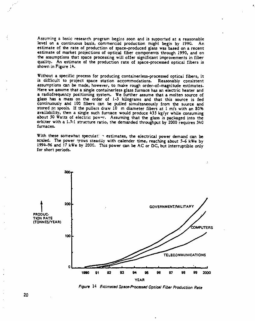
Assuming a basicresearchprogram beginssoon and issupportedat a reasonablelevelon a continuousbasis,commerciaJ productionmight basin by 1990. Anestimateof the rateof productionof space-producedglasswas based on s recentestimateof market projectionsof opticalfibercomponents through1990,and onthe assumptionsthatspace processingwilloffersignificantimprovementsinfiberquality.An estimateof the productionrate of space-processedoptic_ fibersisshown inFigure14.
Without a specificprocessforproducingconta_nerless-processedopticalfibers,itis difficultto projectspace stationaccommodations. Reasonably consistentassumptionscan be made, however,to make rough order-of-magnitudeestimates.Here we assumethata singlecontainerlessglassfurnacehasan electricheateranda radiofrequencypositioningsystem. We furtherassume thata molten sourceofglass has a mass on the order of 1-3 kilograms and that this source is fedcontinuously and I00 fibers can be pulled simultaneously from the suurce andstored on spools. L_the pullers draw 10 m diameter fibers at 1 m/s with an g0%availability, then a single such furnace would produce 435 kg/yr while consumingabout 50 Watts of electric pow=_r. Assuming that the glass is packaged into theorbiter with a 1.5"I structure ratio, the demanded throughput by 2000 requires 340furnaces.
With these somewhat specular! 4 estimates, the electrical power demand can bescc[ed. The power _,rowssteadily with calender time, reaching about 5-6 kWe by1994-96 and _7 kWe by 2000. This power can be AC or DC, but interruptLble onlyfor short periods.
l 200 GOVERNMENT/MILITARYPRODUC-TION RATE(TONNES/YEAR)
S
100
TELECOMMUNICATIONS
0
1SKI0 91 92 93 94 96 9§ 97 98 99 2000
YEAR
Figure 14 Estimated Space-ProcessedOptical Fiber ProducrJonRate
20
1985027415-032

2_1._i Materials Science Laboratory
Materials Processing in Space (MPS) is at an early phase of evolutionarydevelopment. At the time of a manned space station MPS will be at verification ofconcept (VOC) and engineering demonstration (ED) phases. These phases will havehad extensive ground-based research and (in many cases) shuttle/Spacelabinvestigation of concept (IOC) phases as precursors. In the period before thedeployment of the space station there must have been at least 5 years ofcontinuous commitment to IOC at a level of at least $30 million per year. Such acommittment would be adequate to support about 50 ground-based (IOC) researchendeavors during one year. In the early years, from these _0 experiments, about 10may be selected for flight and accommodation on the space station. [n addition, amodLfication to these l0 experiments, or 10 new experiments, would take placeeach year. Should the MPS facility aboard the space station be made available tointernational participants, there would probably be a doubling of experimentalactivity.
The most important advantages of the space station over the shuttle/Spacelab arethat it would provide experimentation facilities with much more power and greatlyextended time in space. The space station would also allow the presence of thehuman experimenter in space. Human experimenters are essential in the earlyphases of MPS development because it is only after a process has been reduced to aroutine that automated manufacture can be considered.
The space station as a facility for MPS can be a national (or international)laboratory for continued research and development in materials that exploit theunique low-gravity environment of space. The early configuration and capabilitieswill be determined by the prior commitment to MPS and the experience gainedthrough use of the shuttle/Spacelab. Because this commitment may justify onlyabout l0 VOC and/or ED endeavors per year_ the start-up of MPS activities aboardthe space station should be designed accordingly. Success, even at this modestactivity level however, will stimulate construction of new facilities as needed. Theindustrial infrastructure and technological capabilities that produced the spacestation should be adequate to meet the requirements for future expansion of MPSactivities.
The followingisa listof candidate,multi-purposeMPS experimentsystems whichmay requireaccommodation ina spacestationmaterialssciencelaboratory,
o SolidificationExperimentProcessingSystemo High GradientFurnaceProcessingSystemo Electromagnetk;ContainerlessProcessingSystemo IsoelectricFocusingSeparationSystemo FloatZone ProcessingSystemo AcousticContainerlessProcessingSystemo ElectrostaticContalnerlessProcessingSystemo SolutionCrystalGrowth ProcessingSystemo Vapor CrystalGrowth ProcessingSystemo Bioprocessing Systemso FluidScienceFacilityo CombustionScienceFacilityo ExtraterrestrialMaterialsProcessingDemonstrations
21
1985027415-033
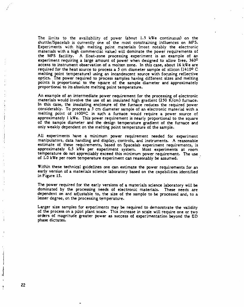
The limits to the availability of power (about 1.5 kWe continuous) on theshuttle/Spacelab is currently one of the most constraining influences on MPS.Experiments with high melting point materials (most notably the electronicmaterials with a high commercial value) will dominate the power requirements ofthe MPS facili_/. A float-zone processing experiment is an example of anexperiment requiring a large amount of power when designed to allow free, 360 °access to instrument observation of a molten zone. In this case, about 16 kWe arerequired for the heat source to process a 5 cm diameter sample oi silicon (l#10o Cmelting point temperature) using an incandescent source with focusing reflectiveoptics. The power required to process samples having different sizes and meltingpoints is proportional to the square of the sample diameter and approximatelyproportional to its absolute melting point temperature.
An example of an intermediate power requirement for the processing of electronicmaterials would involve the use of an insulated high gradient (250 K/cm) furnace.In this case, the insulating enclosure of the furnace reduces the required powerconsiderably. To process a 5 cm diameter sample of an electronic material with amelting point of I#00oc in such a furnace would require a power source ofapproximately I kWe. This power requirement is nearly proportional to the squareof the sample diameter and the design temperature gradient of the furnace andonly weakly dependent on the melting point temperature of the sample.
All experiments have a minimum power requirement needed for experimentmanipulators, data handling and display, controls, and instruments. A reasonableestimate of these requirements, based on Spacelab experiment requirements, isapproximately 0.5 kWe per experiment system. Most experiments at roomtemperature do not appreciably exceed this minimum power requirement. The useof 1.0 kWe per room temperature experiment can reasonably be assumed.
Within these technical guidelines one can estimate the power requirements for anearly version of a materials science laboratory based on the capabilities identifiedin Figure 15.
The power required for the early versions of a materials science laboratory will bedominated by the processing needs of electronic materials. These needs aredependent on and adjustable to, the size of the sample to be processed and, to alesser degree, on the processing temperature.
Larger size samples for experiments may be required to demonstrate the validityof the process on a pilot plant scale. This increase in scale will require one or twoorders of magnitude greater power as success of experimentation beyond the EDphase dictates,
_, 22
m
1985027415-034

"_{I FIGURE 1_: F..STIMATEDPOWER REQUIREMENTS FOR EAKLY VERSIONS OF MSL
ExperimentalMutli-Purpose Processing Sample Power Heating
.i! Experiment Facilities Tem_ecr)ature Diameter(cm) Source(kWe) Other(kWe)t
i'), one (I) high-power 1500 5 16 0.5electronic materialsprocessing
four (4) intermediate 1500 5 _ 2.0power electronicsmaterials processing
five (5) room temperature 25 - - _.0(pharmaceutical and other)
Subtotal: 10 multipurpose experiment systems 20 7,5Approximate Total : 30 kWe
2.1.6 Need For Uncommitted Power
The preceding materials processing missions represent potential commercialenterprises at this time. It is the nature of commercial enterprise during the early
- investigation of concept phase that specific market areas and magnitudes arespeculative estimates. The NASA reference mission set is a reasonable scenario ofmission development based on current knowledge of projected product demand,
1 current understanding of microgravity processes, and estimates of future
t development of competing processes. It is possible, even likely, that the actualcommercial materials processing mission set in the I990s will be significantly! different than currently projected; some of the missions projected today will not
:i become commercial successes and other missions not yet conceived will be•I successful ventures.:I
1 Although specific details of the commercial MPS mission set cannot be confidently
:It predicted, the NASA reference set represents a reasonable projection based oncurrent knowledge and credible assumptions. A number of gener=dizations can bemade of likely market trends. For instance, it is clear that a,_V commercialprocess must develop through the various phases discussedabove. Any new processunder development will likely consume at least one kilowatt during the verification
[ of concept phase and more during the engineering demonstration phase, eventually
t growing at 2-10 kWe/yr once a commerciai market is established. If new materialsand processesare to be developed, then sufficient power must be made available to1 progress through the pilot/prototype phases. If a number of processes are to bei developed as the commercial opportunities are seized, then a surplus of power must, be available to test these processes. This means that, whatever power level is
required to satisfy the demand of existing missions, additional power is necessary if' new commercial missionsare to be developed.
23iI
1985027415-035

If the space stationpower levelisdeterminedby assessingthe requirementsofpredefinedmissions,then the commercial MPS market volume willbecome a self-fulfillingprophecy.There willalwaysbe justenough power availableto satisfytherequirementsof theplannedmissionset,and neverenough todevelopnew missions.
: Although this might be a satisfactory approach to fulfillir_ the requirements of apre-planned program, it would not satisfy a market-driven commercial demand.The commercial attractivness of materials processing in space therefore dependsto a large extent on the availability of ample power beyond that which iscommitted to established missions.
2.1.7 Housekeepin 8 Power
The previous electrical power requirements are all for mission needs. A manned: spacestationhascertainpower requirementsbeyond missionneedsjustto maintain
utility,or housekeeping,functions.These functionsincludelifesupportsystemoperations,lighting,communications/telemetry,thermal control) and datamanagement. These power requirementshave been investigatedin a previousBoeing study of a Space OperationsCenter (ref.22). A breakdown of therequirementsisgiven inFigure 16. The referenceconfigurationisforan eight-Pe:soncrew witha highlyclosedenvironmentalcontrol/lifesupportsystem.
: An investigation of the various contractors' reports of the NASA Space StationNeeds, Attributes, and Architectural Options study revealed a remarkably closeagreement for those contractors that estimated housekeeping demand. Theestimated requirements scale with crew size when the life support system is open.Comparing the various studies, the housekeeping power requirement is3.70+0.56 kW/crew-member. Figure 17 shows how the housekeeping demand islikely to change with time. The bottom curve shows the power demand with an :open ECLSS and a minimum crew size-about 20-30 kWe.
The middle curve shows the requirements for the CDG reference crew size) whichsta.-ts at eight people in 199I and grows to ten in 2000. There are considerations tovary crew size over different numbers. Assuming a space station which grows inscope and crew size, it is likely that the ECLSS loop will gradually become closedin the late [990's as our familiarity with space station operation grows and theECLSS technology advances. The top curve in Figure 17 shows the housekeepingpower requirements as the space station crew size grows to [6 and advancedECI_SS closure is developed. "By the year 2000, the housekeeping powerrequiremen ,s may grow to 75 kWe. This value must be added to the mission powerrequirements to determine the total space station power needs,
2. l.g Electrolysis Propellant Production
When space-based orbital transfer vehicles (OTVs) are added to the space stationsystem, they willlikely use H2/O2 propellants. Extreme caution must be taken inlaunching these propellants in the space shuttle. The safety hazards associatedwith transporting liquid hydrogen and oxygen complicate the launch integration andnecessitate massive tankers. The tanks must be much more massive and complexfor liquid hydrogen and oxygen than for water. The launch safety can be greatlysimplified and the actual launch mass lightened if the propellant is transportedfrom earth to the space station as liquid water and thus electrolyzed to its H2/O 2constituents at the space station. If sufficient power were available for
: electrolysis for OTV propellant production, then this might become a desirablemission,
I
z4
t
1985027415-036

P
• _ - ,
BEFERENCE CONFIGURATION INTERMII"I'ENTLOAD ....
SUNLIGHT OCCULTED.ee POWERi i
' AC IX: AC DC AC DC
• LIFE SUPPORT 7,111R¥ 10_OgW 6,565W 2,610W 3,8SOW 3.75(N/• COMMUNICATIONS/TELEMETRY - 9_370W - 9__7_Y• DATA MANAGEMENT SYSTEM - 1,000W - .1,000W• PROPULSION SYSTEM (HEATERS) - 200W - 200.¥• THERMAL CONTROL SYSTEM 300W 2,00_¥ 300W 2.000W• ATTITUDE CONTROL SYSTEM - 2SOW - 250W• ELECTRICAL POWER SYSTEM
LOADS 12,S00W 4_00W 12,500W 4_00W• (BATTERY RECHARGE FOR - |29_00_) -- -
HOUSEKEEPING LOAO)
• 19,919W 27,522 ': 19.365W 19,_N 3,850W 3o750W(S7,42SW!
•ReFerence Only
Figure 16 Elec_'ical Load Summary for Referenc_8.PersonStation
100
60 CLOSED ECLSS LOOP16 PERSON CREW
POWER(KW)
40 CDG REFERENCEOPEN ECLSS LOOP
LOWER BOUKDP- 3.70 + 0.56 KW/CREW-ME_SER2(:
(] z ! Z ' i .... I I I l I
1991 92 93 94 95 98 97 g8 99 2000
"rEAR
Figure 17 HousekeepingPower Requirements
25
1985027415-037

The propellant required for one round trip of an OTV from a low-earth spacestation to geosynchronous orbit will be about 20,000 kg. The electrical powerrequired for electrolysis of one kilogram of water is about # kwh. By the year2000, the projected traffic for a space-based OTV is about six round trip flights peryear. If all the propellant for these flights is transported in the orbiter as waterand electrolyzed on the space station in low earth orbit, then an additional 55 kWeof power would be required at the space station. It is unlikely that this missionwould be implemented if the additional power were to come from solar panels, butif the incremental power were easily available from a reactor_ then it mightbecome a viable approach.
2.I.9 Summary of Power Requirements
The electrical power requirements are summarized in Figure lg. The requirementsare divided into three categories; mission loads, housekeeping loads9 andelectrolysis power for propellant production. Curve A represents the NASAstandard reference mission set. This is the summary of average power required formissions currently planned in the NASA space station program.
The minimum space station power capability must include more power than just theaverage required for missions. It must include housekeeping loads and some excessfor peak loads. Curve B represents the minimum capacity of a space station whichcould satisfy the MRWG reference mission set. It assumes a 30 percent peakingfactor on the mission requirements and an open ECLSS loop which uses 3.7 kW percrew member. This minimum power scenario begins with 90 kW In 199l and growssteadily to 200 kW by 2000. Thus, a space station will require at least 200 kW justto satisfy the MRWG reference mission set with minimum housekeeping for a 12person crew.
If the commercial materials processing volume were driven primarily by marketconsiderations rather than be.=ngconstrained to available powe," levels, it is likelythat higher power would be demanded. Curve C represents the power requirementsin a market-driven scenario. It was assumedin projecting this curve that each newmaterial being developed follows a market demand growth like that of Figure 9. It'vas also assumed that three processes are eventually commercialized for crystalgrowth; electroepitaxy, chemical vapor transport, and directional solidification;and that one new product is developed for each process every three years. Curve Calso includes pharmaceutical processing by electrophoresis for six products andisoelectric focusing for one more product by the year 2000, and optical fiberproduction as shown in Figure t#. An open ECLSS loop and a 30 percent ixakingfactor was assumed for Curve C. This market-driven scenario leads to rapid powerdemand growth in the late [990's, reaching 330 kWe by 2000.
As the space station evolves and the crew size grows, a permanent mannedpresence will require increasing closure of the environmental control and lifesupport subsystems (ECLSS). Partial closure of the space station ECLSS involvesrecycling waste water and atmospheric components, including carbon dioxide andnitrogen. Curve D depicts a space station power growth profile which reflects anopen ECLSS loop for the initial space station and gradual upgrading to a partiallyclosed loop by the year 2000.
Finally, Curve E represents the power requirements if water electrolysis in space isused for production of propellant for a space-based orbital transfer vehicle. Theprojection assumestwo flights per year by [997 and six flights per year by 2000.
?6
1985027415-038

q_0 p"
: 400 - _ITH OTV [ UNCONSTRAINED POWER
WATER ELECTROLYS IS I GROWTH SCENARIOS .
300- WITHPARTIALLYCLOSEDECLSSJ
•, POWERLkW}
CDG PLANNED CAPACITY
i MRWG REFERENCE MISSIONS "_'
t
,! 100 "
.l
I 0 . I I I, I . t I I l, ! l__1991 92 93 94 95 96 97 98 99 2000
YEAR
Figure 18 Summary of Space Station Power Requirements
Z7
1985027415-039

2.1.10 Emergency Power/Safe Haven Power
A reliable source of auxiliary power, but not a load to oe supplied by the nuclearreactor power, mustalso be provided on the. space station in case of .... lure o-_ theprimary powersource. This auxiliary supplyshouldbe capableof sustaininglifesupport and communicationsoperationsunder emergencyconditions. A spacesta_on ground operationsrequirement being consideredis that an emergencyshuttle flight cc,uld always be available for e taunch to the space station for arescue mission within 21 days, t,_aximum. The _erage power required dJring such_.mergency conditions wall likely depend on spet.,iics of space station design andcrew size, but )_0 kWe for an g person crew seems to be a reasonable estimate. Theemergency power supply should therefore be capable of highly reliable supply of.10kWe of electrical power for a period of 21 days. If more than the normal crewsize is to be accommc,.4ated, such as at crew change, then higher power levels willbe required. This poaer includes life support, communications, and any powerwhich would be required for reactor restart or removal following emergencyshutdown. Some versions of the emergency power/safe haven powe- supplies haveseparate energy storage which can be dedicated when main power is lost. Otherconcepts show the power for emergency or safe haver, ,eing drawn from the mainpower system.
2.2 AdditionalMissionFactors
The magnitude of the electrical power load is not the only factor that tends tofavor a nuclear power source for space station missions over a solar system. Otherfactors are summarized in Figure 19.
FIGURE 19: NUCLEAR POWER SYSTEM BENEFITS
o System scaleability to high power levelso Power generation system size independent of orbito Potential elimination/minimization of _xclusior, volumes
o Insensitivity to shadowing from large structureso Low drag (altitude dependent)o Controllabilityo Insensitivity to natural environment
Since a solar power sourcu can only generate power while in sunlight, the arraysmust be sized atco to supply energy storage for nightside use. The energy storagewill be either a battery, regenerative fuel cell, or flywheel. The solar array, powercorwersion, and power conditioning equipment are sized for energy storagerecharge, the load, and losses. Thus, a solar system with a 100 kWe mission loadmight have to generate at least 200 kWe on the sunlit side of the orbit. This is nottrue of a nuclear power system, where the power level does not include orbitalconsiderations, i.e. recharge of energy storage. If load leveling is used, energystorage would be included and rech.,rge of the energy storage would be a load onthe reactor.
Z8
1985027415-040
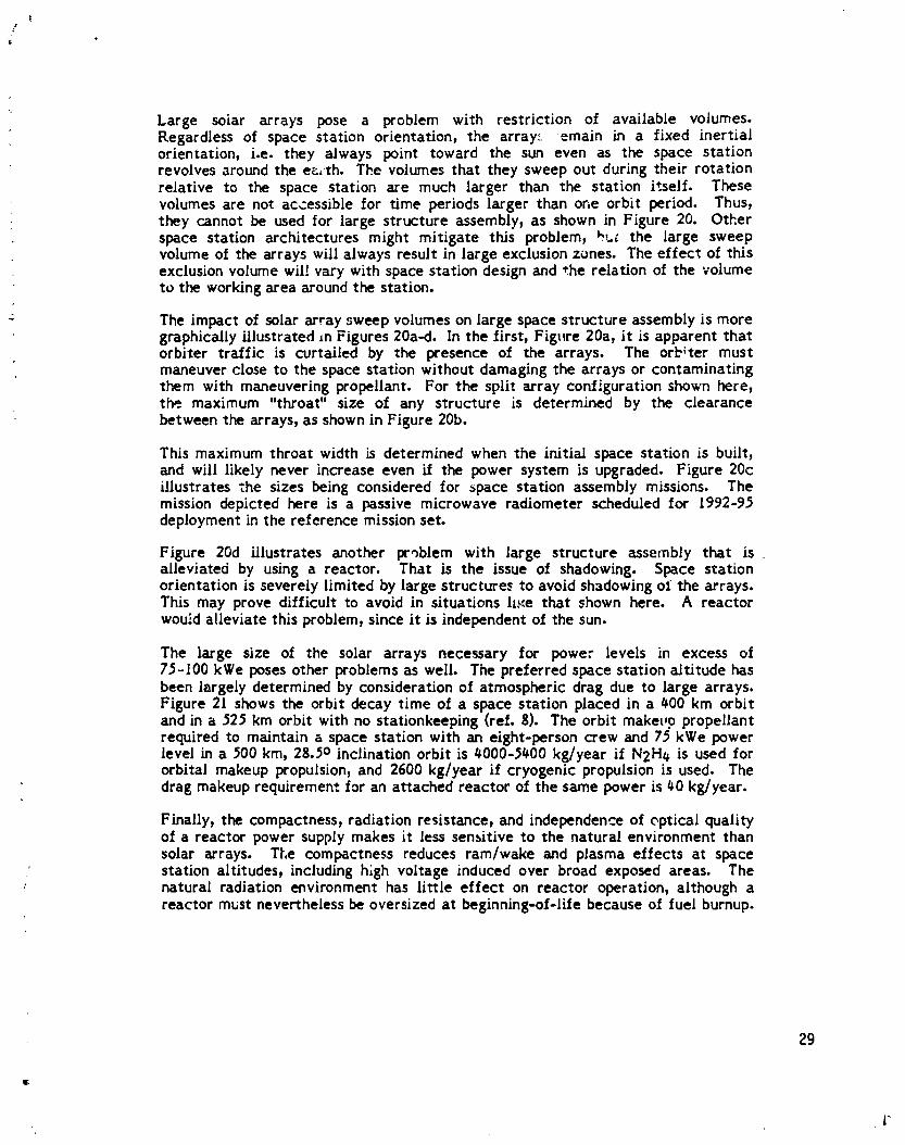
!/
Large solar arrays pose a problem with restrictionof availablevolumes.Regardlessof space stationorientation)the array: emain in a fixed inertialorientation)i.e.they always point toward the sun even as the space stationrevolvesaroundthe e_,rh.The volumesthatthey sweep out duringtheirrotationrelativeto the space stationare much largerthan the stationitself.Thesevolumes are not accessiblefor time periodslargerthan one orbitperiod. Thus)they cannot be used forlargestructureassembly9as shown in Figure20. Otherspace stationarchitecturesmight mitigatethisproblem,hu_ the large sweepvolume of thearrayswillalwaysresultinlargeexclusionzones. The effectof thisexclusionvolume willvarywithspacestationdesignand the relationof the volumeto theworkingareaaroundthe station.
The impact of solararraysweep volumeson largespacestructureassemblyismoregraphicallyillustrated=nFigures20a-d.Inthe first_Figure20a_itisapparentthatorbitertrafficis cvrtalledby the presence of the arrays. The orbitermustmaneuver closeto the spacestationwithoutdamaging the arraysor contaminatingthem with maneuveringpropellant.For the splitarrayconfigurationshown here_the maximum "throat"sizeof any structureis determined by the clearancebetween thearrays_asshown inFigure20b.
Thismaximum throatwidthisdeterminedwhen the initialspace stationisbuilt,and willlikelynever increaseeven ifthe power system isupgraded. Figure20cillustratesthe sizesbeingconsideredfor space stationassembly missions. Themissiondepictedhere isa passivemicrowave radiometerscheduledfor 1992-95deploymentinthereferencemissionset.
Figure 20d illustratesanother problem with large structureassembly that isalleviatedby usinga reactor. That is the issueof shadowing. Space stationorientationisseverelylimitedby largestructurestoavoidshadowingof thearrays.Thismay provedifficultto avoidin situationsh_e that shown here. A reactorwouidalleviatethisproblem,sinceitisindependentof thesun.
The large size of the solararrays nece_ary for power levelsin excess of75-100kWe posesotherproblemsas well.The preferredspacestationaltitudehasbeen largelydeterminedby considerationof atmosphericdragdue to largearrays.Figure2! shows the orbitdecay time of a spacestationplacedina _00 km orbitand ina 525 km orbitwithno stationkeeping(ref.$). The orbitmaket,ppropellantrequiredto maintain& spacestationwith an eight-personcrew and 75 kWe powerlevelina _00 km_ 28.5oinclinationorbitis_000-5#00kg/yearifN2H# isused fororbitalmakeup propulsion,and 2600 kg/yearifcryogenicpropulsionisused. Thedragmakeup requirementforan attachedreactorof thesame power is_0 kg/year.
Finally_the compactness,radiationresistancepand independenceof epticalqualityof a reactorpower supplymakes itlesssensitiveto the naturalenvironmentthansolararrays. The compactness reduces ram/wake and plasma effectsat spacestationaltitudestincludinghighvoltageinducedover broad exposed areas. Thenaturalradiationenvironmenthas littleeffecton reactoroperation,althoughareactormust neverthelessbe oversizedat beginning-of-lifebecauseof fuelburnup.
29
i" I
1985027415-041

30
l
1985027415-042


Figure20b OrbiterDockedAt SpaceStation
,i
32t
&
1985027415-044

33
l
1985027415"C

Figure20d ArrayShadowingFromLargeStructure
34
I
1985027415-046

• AVERAGE SOLAR ARRAY
• NASA NEUTRAL ATMOSPHERE
"WIT} STAT[ONI_ EPINE500 ...6.._ _ 110KW
-"_,e._. -- _ _ 210 KW
450 '
_ - ,, "-,_ _ ..
'_-"= t WiT_OUT TATIC KEEPING200,:
420 KW 210 KW \110 CW150
\100.
0 20 40 60 80 100TIME, DAYS
SPACE STATION PROPULSIONREQUIREMENTS STUDYCONTRACT N_$ 3-23353
Figure ZI SpaceStationOrbit De_y Time
35
i
1985027415-047

3.0 SPACE STATION SYSTEM ARCHITECFURE
The space stationarchitectureand designrequirementshave yet to be defined,Severalgeneralarchitecturaloptionsarestillunderconsideration,and preliminaryspace station design is expected to begin in late tgg4. The space station system,however, will have a number of elements in addition to the manned space stationfacility, including vehicles and platforms. These elements and their anticipatedcapabilities in the mid to late 1990's are summarized below. Although the nuclearreactor electrical system will not be involved with all the elements of the spacestation system, all the elements are described in order to provide a completepicture so that the analyses of on-board, tethered, and free-flyer vehicles withreactors can be made and the system interrelationships can be evaluated.
_.l Summary of Major Elements
The major elements of the complete space station system are depicted inFigure 22. The items inside the shaded circle are considered space station elements.The reference space station system consists of the manned sp:_cestation_ unmannedplatforms, an orbital maneuvering vehicle (OMV), and an orbital transfer vehicle(OTV). This system is expected to be in place by the mid-1990's - the time framebeing considered for early reactor operation in this study. Additional elementsbeing considered for a growth space station system in the late 1990's include ageosynchronous manned space station, a manned polar platform, a manned orbitalmaneuvering vehicle, and manned orbital transfer vehicle, and shuttle-derivedcargo launch vehicles. Each of these elements are described below.
3.2 STS CapabLLifies
For the reference space station of the early to mid 1990's, the launch vehicle fromearth to low earth orbit will be the space shuttle, or STS. The STS consists of the
°! two solid rocket boosters, the external tank, and the orbiter. All payloads to orbit! must fit within the constraints of the orbiter cargo bay. The dimensions of the_I cargo bay which are availablefor payload are 1g.3m longand _._ m diameter. The
launch capabilities from Kennedy Space Center are shown in Figure 23 (ref. 9).Currently, the orbiter can place 19,500 kg in a 500 km high, circular orbit with2g.5o inclination. With improvements planned for the main engines, by the time a
1 space station is in orbit, the orbiter payload mass is expected to be at least25,000 kg. This latter value ha_ been used in this report as the STS launch
; capabili_.
3.3 Space Stationt
3.3.1Space StationModules
Althougha spacestationdesignh_snotyet been prepared,itisexpectedto contain: the following types of modules: resource modules, living quarters, laboratory
modules, logistics modules, servicing structure, and a manipulator system. It mayalso contain multiple berthing adapter modulest if the specific design warrants it.
The resource module provides the space station electrical power, communications,data processing, attitude control, and orbit reboost. This module also has athermal control/radiator system to reject heat from the resource module
: equipment and possible equipment in other station modules. This resource moduleincludes built-in capability (scar) for future power and thermal control growth.
36
1985027415-048

37
1985027415-049

m
• Shuttle performance is e function of program vlriables(Launch date, enginethrust, individual orbiter weight,
40 etc.) and must be determined on I caseby casebmis.
• Cargo weight includesall payload itemsend payload80 - support services
•Dm shown for 28.5 a_gree inclination only
i • Shaded areal representprimary regionseffecteclby30 • program variables. Payloadsrequiring performance
INTEGRAL in these regionsshouldverify capability with JSC.._ ._ 60 _t_;_= _ OMS asearly aspossible.
g g NLo u_ _. = SECONDOMS
10 20. __q____ ADDED
'_ _ THIRD OMS KIT
o o__3100 200 300 400 600 600 700 800
CiRcuLAR ORBIT ALTITUDE, NM!
! I.._. I I I I Ii
! _ 400 600 800 1000 1200
CIRCULAR ORBIT ALTITUDE, KM
; Fig_,re23 Near- [erm STS IZayload Mass to Circular Orbit-KSC Launch, Defivery Only
!
!11t
38
A
1985027415-050
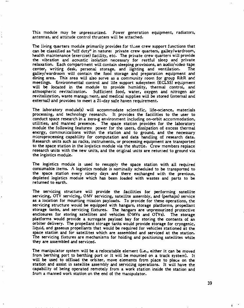
This module m_y be unpressurized. Power generation equipment, radiators,antennas, and attitude control thrusters wtll be attached.
The living quarters module primarily provides for those crew support functions thatcan be classified as "off duty" in nature= private crew quarters, gailey/wardroom,health maintenance (exercise) facility, etc. The private crew quarters will providethe vibration and acoustic isolation necessary for restful sleep and privaterelaxation. Each compartment will contain sleeping provisions, an audio/video tapecenter, writir, g desk, personal storage, and lighting and ventilation. Thegalley/wardroom will contain the food storage and preparation equipment anddining area. This area will also serve as a community room for group R&R andmeetings. Environmental control and life support subsystem (ECLS5) equipmentwill be located in the module to provide humidity, thermal control, andatmospheric revitalization. Sufficient food, water, oxygen and nitrogen airrevitalization, waste management, and medical supplies will be stored (internal andexternal) and provideo to meet a 2t-day safe haven requirement.
The laboratory module(s) will accommodate scientific, life-science, materialsprocessing, and technology research. It provides the facilities to the user toconduct space research in a zero-g environment including on-orbit accommodation,utilities, and manned presence. The space station provides for the laboratorymodule the following features= power for the users, dissipation of excess thermalenergy, communications within tl-_ station and to ground, and the necessarymJcroprocessing capability for computation and data handling of research data.Research units such as racks, instruments, or processing equipment are transportedto the space station in the logistics module via the shuttle. Crew members replaceresearch units with the new units, and the original units are returned to ground viathe logistics module.
The logistics module is used to resupplv the space station with all requiredconsumable items. A logistics module is nominally scheduled to be transported tothe space station every ninety days and there exchanged with the previous,depleted logistics module which has been loaded with wastes and parts to bereturned to earth.
The servicing structure will provide the facilities for performing satelliteservicing) OTV servicing, OMV servicing, satellite assernbly, and (perhaps) serviceas a location for mounting mission payloads. To provide for these operations, theservicing structure would be equipped with hangars, storage platforms, propellantstorage tanks, and servicing fixtures. The hangars are unpressurized protectiveenclosures for storing satellites and vehicles (OMVs and OTVs). The storageplatforms would provide a surrogate payload bay for storing the contents of anorbiter delivery. The propellant storage tanks would provide storage for cryogenic)liquid, and gaseous propellants that would be required for vehicles stationed at thespace station and for satellites which are assembled and serviced at the station.The servicing fixtures are mechanisms for holding and positioning satellites whilethey are assembled and serviced.
The manipulator system will be a relocatable element (i.e., either it can be movedfrom berthing port to berthing port or it will be mounted on a track system). Itwill be used to offload the orbiter, move elements from place to place on thestation and assist in satellite assembly and servicing operations. It will have thecapability of being operated remotely from a work station inside the station andfrom a manned work station on the end of the manipulator.
39
1985027415-051

3.3.2 Space Station. Configuration Options
In order to conduct trade studies of reactor-powered space station configurations,it was necessary to select a reference space station concept. At the time of thisstudy, there is a wide variety of station architectural concepts still beingconsidered by the Concept Definition Group (CDG). Figure 2# showssome of theseconcepts.
The concept selected as the reference space station for this nuclear space stationstudy is of a class of concepts referred to as "gravity gradient con.¢pts", related tothe power tower geometry of Figure 2#. The gravity gradient stabilized spacestation concept was selected because it was judged to be the concept mostamenable to adding a nuclear reactor system aiter the initial station starting as asolar powered station. This judgement was based on looking ahead at the potentialreactor and radiator configuration, and their integration requirements. Thisselection did not result from a thorough evaluation of the configuration options andis not to be construed as a recommendation for the space station design; it merelyserves the purpose of assigning a common data base for a comparison of the variousreactor-space station configurations. As will become apparent in Section $ below,this selection did not bias the results of the trade studies.
3.3.3 Reference 5pace Station Design Data
The specific configuration used here for reference space station design data isshown in Figure 25. The parameters were derived from numerous space stationstudies at Boeing and other aerospace companies. The mass, volume, and frontalarea normal to the orbit plane data for this configuration are summarized i,_Figure 2(;. The resource module mass has been reduced from that shown in earlierstudies by the massof the solar arrays, gimbals, energy storage, and radiators.
The orbiter is assumed to be docked to the space station for 14 days out of every90-day cycle. Its mass and frontal area are included in space station globalproperties as a weighted average. The OTVs are assumed to be docked at the spacestation for 76% of the time. The total space station pru_erties are shown in
I Figure 27, Lor an initial space station (early 1990's) and a growth station! (late 1990's). For this study, a growth space station with a crew of eight wast assumed,since several studies used this crew size. The power generation subsystem! was excluded from these data.
The space statio_ orbit used in this study is a 500 km high circular orbit with aninclination of 28.5o. A nominal atmosphere in this orbit, valid for average dragcalculaxions over -_complete I l-year solar _'cle, has a density of 3.18x 10⁻¹³"kg/m,:_,This result_ in a drag force for the initiaJ space station of 4.g3 mN for theinitial space station, and I h2 mN for the growth station.
]1.4 Unmanned Platforms
The space station system will also include several unmanned platforms which serveas mountin K bases and resource modules for unmanned payloads. These platformswill be capable of being placed in low earth orbit at any inclination, and will beserviced from the orbiter or from the space station_ with the O;vtYwhen necessary.Current plans call for one unmanned platform co-orbiting with the manned spacestation in a 28._o inclination _d another in a high inclination circular orbit with anAltitude of 700-7_0 km.
40
l
1985027415-052

ORIGINAL PAGE ISPOOR QUALITY
#
_ _'
41
1985027415-053
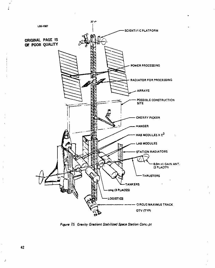
z'..P-
I.S_1o81 I SCIENTIF IC PLATFORM
ORIGINALPAGEISOF.POORQUALITY
POWER PROCESSING
RADIATOR FOR PROCESSING
ARRAYS
POSSIBLE CONSTRUCTION
, ERRY PICKERI
.° _
MODULES X C3
I LAB MODULES
STATION RADIATORS
_,f; 6,Ore HI GAIN ANT.
(2 PLACE¢;)
_'_. ;¢ THRUSTERS
_ -p, rANKERS
I (3 PLACES)
)GISTICS' _',, CIRCU_ MAXlMUS TRACK
OTV (TYP)
Figure 25 GraviW Gradient Stabilized ,._oace Station Conc:pt
42
.i
1985027415-054
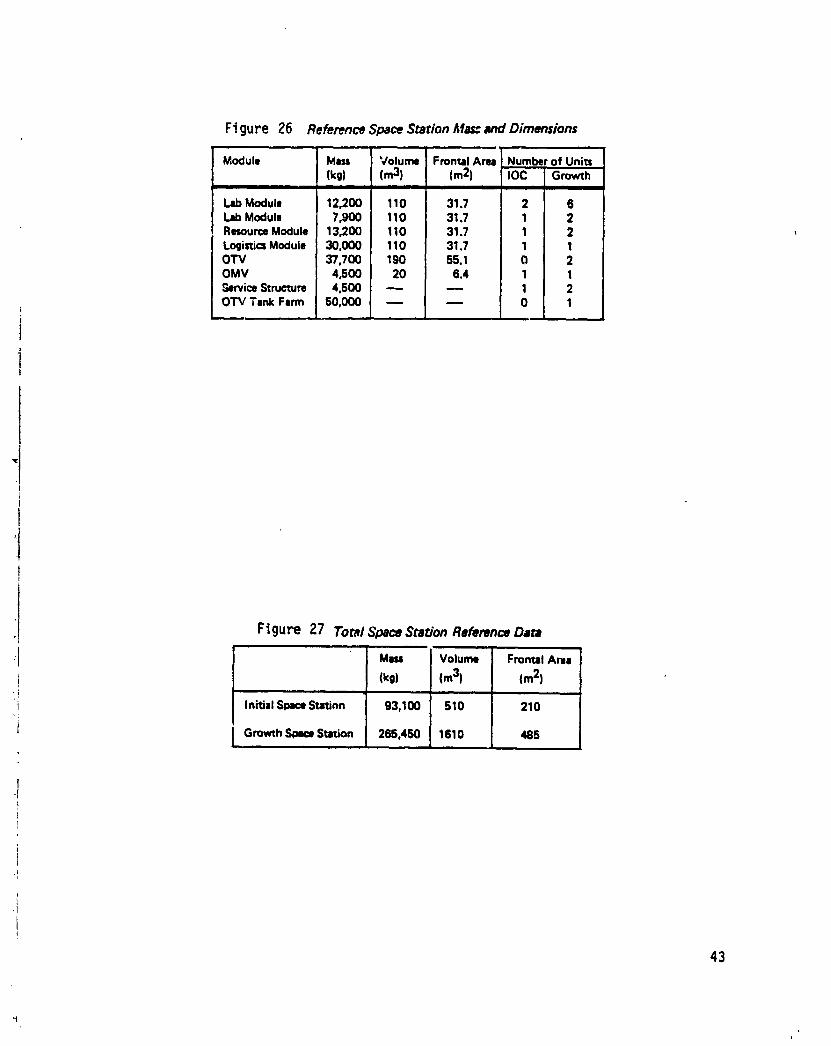
Ftgure 26 Reference Space Station Ma_ and Dimensions
Module Mm Volume FrontalArea Numberof Units(k0) (m3) (m2) IOC Growth
LabModule 12,200 110 31.7 2 6LabModule 7,900 110 31.7 1 2ResourceModule 13,200 110 31.7 1 2Logini¢=Module 30,000 110 31.7 1 1OTV 37,700 190 55.1 0 2OMV 4_00 20 6.4 1 1_rvic8 Structure 4,500 _ _ 1 2OTV Tank Farm 50,000 _ _ 0 1
F_gure 27 Tom/Space Station Reference Data
MIll Volume FrontalAm=
! (kg) (m3) (m2)
I InitialSmmeStation 93,100 510 210
t GrowthSpaceStation 265,450 1610 485m
43
i
1985027415-055
.=
3._ Orbital Maneuvering Vehicle (OMV)
The OMV _o a general-purpose, remotely controlled, free-flying vehicle capable ofperforming a variety of missions in space. One configuration is illuszrated inFigure 2g. The initial OMV will be delivered to orbit by the shuttle, controlled
* from the shuttle, and returned to earth in the shuttle after performing itsmission(s). Current NASA planning includes a new start in 1995 for the basic OMVso that the vehicle will be operational in the early 1990s. The plan also includesex_anding the capability of the vehicle to remain in orbit for an extended period oftime by adding a solar array power source and by enabiing it to be refueled in orbit.With these capabilities, it can be left in orbit and need not be returned in theshuttle. OMV capabilities to deliver and retrieve payloads in higher altitudecoplanar orbits are shown in Figure 29. For this study, it is important to note thatthe OMV should be capable of placing an 1$,000 kg payload in a I200 km orbit,when deployed from the space station, or to place and return a 7000 kg payloadto/from the same orbit.
3.6 Orbital Transfer Vehicle (OTY)
The orbital transfer vehic : considered in this system analysis will be a cryogenicreusable upper stage vehic,a that will be stationed at the space station starting inthe mido1990ts. There are a variety of OTV concepts being considered, so it is zooearly to define its characteristics. The studies by Boeing and Martin Marietta,initiated in 3uly, 1994, will result in conceptual designs and predicted performance.Its primary mission will be to launch satellites from the space station to
eOSynchronousorbit. One potential configuration is illustrated in Figure 30el. 10). This design would be capable of transferring a round trip payload of
5,000 kg between the space station and geosynchronousorbit.
A space-based OTV might also be used to transfer payloads to low earth orbitswhich are out of plane with the space station and require large A v from thestation. Another application might be to place massive payloads into low & vorbits, such as to transfer heavy fuel tank payloads between the space ,L-_tJonandother low earth orbits. This mission will be discussedin Section g.$ as a means ofplacing a reactor in a somewhat higher orbit than the space station.
3.7 Advanced Space Station System Elements
At the present time, the Space Station program concept projects, by growth,beyond the year 2000. Boeinb, and others, have looked at advanced space stationsystem concepts that go beyond the first station. These advanced concepts includethe following: geosynchronous space station, polar orbit space station, rr.=_.nnedOMV and OTV. and heavy lift launch vehicles. Each of these is described below.
3.7.1 _wonotm Orbit Space Station
A space station in geosyr_chronous orbit (GEO) may become an economic venture inthe future. The primary mission for a GEO space station would be communicationssatellites and platform servicing. The primary operational mode would be satelliteservicing by a manned servicing vehicle that would be permanently stationed at theGEO space station. A secondary mode would be retrieving smaller satellites to thespace station for servicing and then returning them to their orbital slot. Asecondary mission would be life sciences research (primarily medical researchlooking at the long-term exposure of ti_e crew to the GEO radiation environment).
44
1985027415-056

ORIGINAL PAC_' |$OF POOR QUALITy
_,"I 4.42m
Figure 28 Orbital Maneuvering Vehicle (OMV)
45
J
1985027415-057

(lo3I_) (t)"20
40, /'- PAYLOAD RETRIEVAL
\ _X\_> W,_o,.=_,_o\ \ ,s,,-_sSECONDS.15
=,. \\\ .O,EC. OEo.
0
100 200 300 400 500 600 700 _ 900 1000 (NMI)• ,,_i, i ,d, • I • | II | m = I , I I
200 400 600 800 1000 1200 1400 1600 1800 (KM)
DELTA ALTITUDE
Figure 29 OMV Perforrnance
46
lL
1985027415-058

A GEO space station could also be used as a platform for civilian and militaryearth and space observation instruments that would be enhanced by the presence ofa crew. Figure 31 shows one GEO space station that was d_veloped !or _n earlierstudy (ref. l I).
3.7.2 Polar Orbit Space Station
In the current NASA planning, an unmanned polar orbit platform has beenidentified as being required to fulfill earth=observation and spac_ physics missionrequirements. In Boeing's space station needs studies (ref 3) was shown aneconomic benefit of having a manned space station principally because the mannedpresence would provide the capability of keeping the instruments serviced on adaily basis. Figure 32 shows a concept for a polar space station that was defined inthis study. The concept would require approximately 20 kW_ of electrical power toserve the missions and housekeeping requirements.
3.7.3 Manned Orbital Maneuvering Ve_cle
In the current NASA Space Station planning, an unmanned OMV i_ defined.However, Boeing (and others) has identified requirements for a manned OMV toenhance the satellite servicing capabilities. This manned OMV would be stationedat the GEO space station. Figure 33 showsa concept for this manned OMV. Thisconcept is sized for a crew of two.
3.7.4 Manned Orbital Transfer Vehicle
In the current NASA space station planning, an unmanned OTV is defined.However, Boeing (and others) has identified requirements for a manned OTV toenhance the capability for servicing satellites located at GEO. This manned OTVwould also be stationed at the GEO space station. Figure 3# showsa concept forthis manned OTV. The crew cabin would be the same as that used for the mannedOMV.
3.7.5 Heavy Lift Launch Vehicle
NASA and the military have sponsoredstudies of future requirements for unmannedHLLV's. Figure 35 showsa potential development schedule for some of the HLLVconcepts that have been defined by Boeing. The first one in particular, referred tobelow as a cargo launch vehicle (CLV), would utilize the existing STS solid rocketboosters on an unmanned launch vehicle to increase the payload to orbitcapabilities by a factor of three. This unmanned, shuttle-derived vehicle wouldremove the orbiter and modify the existing external tank (ET) by placing thepayload in the noseof the ET.
47
|
1985027415-059

1985027415-060

mc.t:m \ ORIGINAL PAGE 18SOLARARRAY OF POOR QUALITY
RADIATOR RCSBOOM CHERRYPICKER
AIRLI_MODULE
LOGISTI(MODULE
HABITAT,_MODULE
CLOSEDCABINSTORM MANNED REMOTESHELTER WDRK STATION
AIRLOCK STORAGEPLATFORMMODULE
Figure .31 GEOSOC Concept No. 2
49
1985027415-061

N_'.4)t
COMMAND • CONTROL• CREW "FLIGHT DECK"• RADIATI04_ SHELTER• EPACESUIT STORAGE
TUNNEL • • EMU RECHARGE
, INSTRUMENT PALLE_" _ /.eMISSiON ADAPTIVE
TO SCIENTIFIC AND \ AIR LOCK
EARTH OBSERVATION
MODULE• FOOD STORAGE• GENERAL STORAGE A
• •LIOUID/GAS TANKAGE(UNPRESSURIZED SECTION)
• WASTE MGMT FACILITY• HAND WASH
HABITAT MODULE• OUiET END
• CREW QUARTERS"URINAL •
liERVICE MODULE SHOWER• BACK-UP COMMAND Ik CONTROL •ACTIVE END• ECLS (PRIMARYI eGALLEY/MESS• EXERCISE AREA (TENTATIVE) •WARDROOMeFOWER SYSTEM •HAND WASH• STATioN CONTROL
oLIMIT_D FOODoCMG$ (2) IrrORAGE•THRUSTER BOOMS
• 02N 2 STORAGE (EXTERNAL)
Figure 32 Polar Space Station Concept
: ORIGINAL PACE iSPOOR QUALITY
50
i
1985027415-062

ORIGINAL PACE IS,.,4,0 OF POOR QUALITY
CENTAUR STRUCTURAL
INTERFACE / _ ROCKET PLUME DOORS (41
UMBILICAL _ / /_HEATI_I'IIELD
\ ,NT[.FAC[ //
.'_..---,'_.": . _,i
_w'rLE /-I_ / I-" '" . -- ¢,_ ,, _-TRUNHION¢AJIqIOFITANO --/ _-'_l L : (" _I'1_ \ SUPPORT
till;l\ _ MISSION
.INTERFACE I _ : _ N2 II_iI\ PROPELL
i ,,,oEzvowJ / \_) _ ,o- ; _ o:t MAOAM / "..,.._i_..i_.._ ,,,,.= . _"--CABIN ATM
/A -- TRANSFER
'*t PRO4PELL J HATCH ,_ _ VESSELTRANSFER v _ RADIATORSMECH
VIEWPORT (2) ._ I
I " I" I_1 I-- ,®-- --I
! " INDE VIEW TOP VIEW
Figure 33 Manned OMV Concept
51
1985027415-063

L
1985027415-064

Drivers: Cost/Delivery Cepabiiiw90 --
• Total reusability ADVANCED85 -- • Integrated structure
i • Propubion breakthrough CARGO80 -- • Automation: flight operations VEHICLE
75 --=¢ 70--OE 65- SHUI"I'LE¢
o DERIVED Drivers: Unique Capabilities/Cost,,. 80- CARGOo" VEHICLE • Vehicle configurationsm 55 -- • Propulsion performance (SSME, LOX/HC)
• Large body ratumzg --
Z 45 -- Drivers: Orbiter Life Extensions& Cost/Flight Reductionalp
"_ 40 -- • El" producibility.¢ * Flight worthiness ncertificationp--J • TPS/SSME life
35 -- SHUTTLE • System constraintsw • Pr_blm subsystems,-,; 3( --O' • Automation: subsystemand ground operationsk-
25 SHUTTLE<(= 20 Driver: Spec. performance (Galileo; USAF at WTR).J>" • Technology available
101980 1985 1990 1995 2000 2005 2010
YEARS
Figure 35 Advanced Launch Vehic/e Projections
(from NASA Space Systems Technology ModelVolume I/A, January 1984)
53
i
1985027415-065
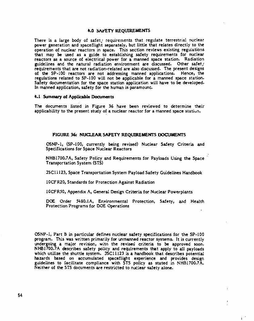
_.0 5AI-_TY REQUIREMENTS
There is a large body of safer,, requirements that regulate terrestrial nuclearpower generation and spaceflight separately, but little that relates directly to theoperation of nuclear reactors in space. This section reviews existing regulationsthat may be used as a guide to establishing safety requirements for nuclearreactors as a source of electrical power for a manned space station, Radiationguidelines and the natural radiation environment are discussed. Other safetlrequirements that are not radiation-related are also discussed. The present designsof the SP°I00 reactors are not addressing manned applications. Hence, theregulations related to SP-100 will not be applicable for a manned space station.Safety documentation for the space station application will have to be developed.In manned application, safety for the human is paramount.
4.1 Summary of Applicable Documents
The documents listedin Figure 36 have been reviewed to determine theirapplicabilityto thepresentstudyofa nuclearreactorfora manned spacestatiun.
FIGURE 36: NUCLEAR SAFETY REQUIREMENTS DOCUMENTS
OSNP-I, (SP-100, currently being revised) Nuclear Safety Criteria andSpecifications for Space Nuclear Reactors
NHBI700.7A, Safety Policy and Requirements for Payloads Using the SpaceTransportation. System (STS)
3SCI 1123, Space Transportation System Payload Safety Guidelines Handbook
10CF R20, Standards for Protection Against Radiation
10CFI_0, Appendix A, General Design Criteria for Nuclear Powerplants
DOE Order 54g0.1A, Ertvironmental Protection, Safety, and HealthProtection Programs for DOE Operations
OSNP-I, Part B in particular defines nuclear safety specifications for the SP-100program. This was written primarily for unmanned reactor systems. It is currentlyundergoing a major revision, with the revised criteria to be approved soon.NHBI700.7A describes safety policy and requirements that apply to all payloadswhich utilize the shuttle system. 3SC11123 ksa handbook that describes potentialhazards based on accumulated spaceflight experience and provides designguidelines to _acilitate compliance with STS policy as stated in NHBI700.7A.Neither of the STS documents are restricted to nuclear safety alone.
54
1
1985027415-066

I't
,!
_ 10CFR20 and 10CFR30, AppendixA are federrJregulations.The former c,ppliesto; any radioactivesourceand sets limitson the allowableconcentrationof each ofi the radionuclidesin the environment. Thiswould be particularlyrelevantincase; of a launchor reentryaccidentinwhich radioactivematerialmight be releasedin_J the atmosphere or in the ocean. The latterregulatesthe designof nuclear
powerplantsingeneraland doesnot particularlyapplyto spacereactors.
DOE Order 5#g0.1AprovLdesforprotectionof thepublicand government propertyagainstaccidentallossand damage due to DOE operations.This is particularlyrelevantfor the SP-100 p_'ogram,in which the space reactorwillbe treatedas aDOE operation. The order encompasses environmental,safety,and health
protection.
i 4.20SNP-I
OSNP-I is divided into two parts: Part A describes nuclear safety criteria forspace nuclear reactors and Part B describes design specifications to ensurecompliance with the policy stated in Part A. Part A describes radiological safetypolicy:
'The policy of the United States for all U.S. nuclear power sources in space isto ensure that the probability of release of radioactive material and theamounts released are such that an undue risk is not presented9considering thebenefits of the mission."
This policy is implemented by defining a dose limitation phil, ,ghy and byestablishing safety design reporting procedures. Part A sped.ties that aPreliminary, Updated9 and Final Safety Analysis Report be prepared at designatedstagesof reactor design and submitted to DOE _or approval and that the reports bereviewed by the Interagency Nuclear Safety Review Panel.
The dose limitation philosophy established in OSNP-I, Part A follows these threeprinciples:
o No practice shall be adopted unless its introduction produces a positive netbenefit;
o All exposures should be kept as low as reasonably achievable, economi,_%technical, and social factors being taken into accountl
o The risk to individuals shall not exceed the limits specified for theappropriate circumstances.
i Safety criteria are also established in Part A for radiation protection in case ofaccidents. The following criteria are to be used to asaess the consequences of ahypothetical accident:
o For individuals, a specific analysis shall be prepared to demonstrate that theaccidental dose is as low as reasonably achievable.
o For populations, a specific analysis shall be prepared to demonstrate that therisk index is as low as reasonably achievable.
The risk index is defined as the sum of the individual accident probabilities timesthe associated integrated population dose.
55
II
1985027415-067

Nuclear safety requirements for a manned space station system must addressradiation protection of the general population while the reactor is in theatmosphere, and radiation protection of space station personnel whil __the reactoris in orbit. The safety impacts on system oesign affect the launch vehicle, reactor,and space station during the different mission phases. The mission phases can L.=separated into ground handling, launch and ascent, reentry, nominal mission,mission emergency, and erd of life.
Reactor design requirements for the SP-I00 reactor program are specified inOSNP-I, Part B. The following safety design requirements are specified=
o The reactor shall be designed to remain subcritical if immersed m water orother fluids (suchas rocket propellants) to which it may be exposed.
o The reactor shall have a significantly effectiv-, negative power coefticient ofreactivity.
o The reactor shall be designed so that no cr.J_.,le launch pad accident) rangesafety destruct actions, ascent abcrt or reentry from space resulting in Earthimpact could result in a critical or supercridcal geometry.
o The reactor shall not be operated (except for zero power testing yieldingnegligibleradioactivityat the time of lau._ch)untila stableorbitor flightpath isachievedand must have a reboostcapabilityfrom low-earthorbitifitisoperatedinthatorbit.
o Two independent systems shallbe provided to reduce reactivityto asubcriticalstate.They shallnot be subjectto common causefailure.
o The reactorshallbe designedto ensuretha_thereisan indepe,-d--ntshutdownheat remov_) system or independentheat removal paths withinthe heattransportsystem to providedecayheat removal.
o The unirradia".Ifuelshallposeno significantenvironmentalhazard.
These designrequirementsimpose certainfunctionalrequirementson the reactorsystem, including:
Reactor Control System - Positive coded teler:,etry sh&ll be required to start upthe reactor. Thus, the reacto st_ali have a reactor cor_trol system which) _.naddition to the design requirement of being capable of initiating reactor start-up,shall be capable of controlling power escalation to full DOV ' l,_vel and of reducingpower to a full shutdown mode. The system shall be capab = .f being operated in adirected positive shutdown mode and of restarting the reactor following ashutdown.
Reactor Protection System - A reactor protection system which includes twoindepen4en_ systems not subject to common cause faLure to reduce reactivity to asubcritical state shall be provided. This system, which is one of the engineeredsafety features, shall be capable of sensing conditions which would Call for reactorshutdown and o# automctticall7 shutting the reactor down, with restr.rt capability.Except for the neutron absorber/reflector elements and their activators) theprotection system shall be independent from the control system. Conditions c_-llingfor automatic reactor shutdown by the protection sy=tem are=
o Failure of the reactor control systemo Failure of the spacecraft attitude control systemo Exceeding of fuel design temperature limitso Failure of Earth/spacecraft reactor control and/or s fety systems
communications system.
56
1985027415-068

The reactor protection system shall have fault detection sensors and shall bedesigned to be able to be tested while the reactor is operating (without actuallychu_ing the reactor down). It shall be capable of performing this function,assuming a single system fsLlure, and shall not be subject to common cause failureswith systems/conditions upon which it is called to activate in case of their failure.The reactor protection system ohall be designed such that any failure of the systemputs the reactor in a safe cordition in .. reasonably short time. The reactorsystems contractor shal_ specify in the detailed technical safety specification
, (subject to DOE approval), the minim.,m ;hutdown reactivity during:
o assembly/testingo groupd handling/storageo transportationo launch
Reentry Core Dispersal Capability - For short-lived orbit missions, a reentry coredispersal capability shall be provided. This capabilit_ will ensure that the reactorcore and activated structural elements will be dispersed such tha_ the NuclearSafety Criteria for Space Nuclear Fission Reactors (Part A) are not exceeded. Thiscapability shall be provided such that the reentry environment of the reactor
i separate from the launch vehicle will initiate and cause the required dispersal with• no active systems required to operate.
i Reactor Control and Safety Systems Communication System - A r_a_tor control
I and safety systems communication system shall be provided such that reactor,reactor control system, power conversion system, and safety systems status may be
t monitored and controlled. Two independent systems shall be provided.
t Instrumens_tion System - An instrumentation system shall be provided whichprovides, t. ough the reactor control and safety systems communication system,
I signals to allow continuous determination of:t
! o Reactor power level (and rate of change)
o Fuel temperatureo Control/reflector element positions
! Status of:
' o Reactor control systemi o Reactor protection systemti o Power conversionsystem
o Spacec,aft attitude control systemo Orbital altitude boost system (short-lived orbit missionsonly)o Independent electrical power source
I
, Core Cooling System - Following a shutdown the core cooling system shall becapable of providing adequate heat removal from the core with sufficientlyindependent shutdo_'n heat removal paths or with an independent shutdown heat
: removal system to prevent the fuel temperature limit from being exceeded and_ safety systems from being inoperable.
Functional requirements can be derived from OSNP-I and imposed on the spacei station system. These include:
57
1985027415-069

)Orbital Altitude Boost System - An orbital altitude boost system shall be providedby the mission agent.-/ (short-lived orbit missions only). This system shall becapable of boosting the reactor to a high altitude orbit following completion of themission or upon mission failure such that the radiation protection safety criteria ofSection 5.2 of Part A (of OSNP-I) are met. Typically, an orbital lifetime of atleast 300 years wilt be required.
Spacecraft Attitude Contrcl System - A spacecraft attitude control system shall beprovided on the spacecraft by the spacecraft system contractor such thatspacecraft attitude can be controlled to permit communication with the reactorcontrol and safety related systems and (for short-lived missions) to permit theorbital altitude boost system to perform its function.
Independent Electrical Power - An independent source of electrical power shall beprovided such that the reactor control system, the reactor protection system, andthe reactor control and safety systems can operate independent of reactoroperating mode or reactor power conversion system operation. This secondarysource of power shall be capable of providing power for safety related systemsoperation and reactor restart capability for a minimum of 2It hours followingfailure of the reactor power conversion system during the spacecraft missionlifetime.
4.3 long-Lived Orbits
Functional requirements stated in OSNP-t) Part 6, included a requirement for anorbital boost system that would place the reactor in a high orbit at end of life orupon mission failure, assuming it was operated in a short-lived orbit. An orbitlifetime of 300 years is suggested. Figure 37 showsthe required orbit altitude Ioca 300 year orbit as a function of reactor power system ballistic coefficient.Atmospheric conditions were taken in a 28° inclination orbit, averaging the t t-yearsolar activity cycle from t99_ until 2294. The ballistic coefficient relates to themass-to-drag ratio of the reactor power system. The range of ballistic coefficientsconsidered in this report is from 16 gm/cm 2 for a free-flyer reactor with itsassociated radiators and fuel processing equipment, to [50 gm/cm 2 for a man-ratedI50 kWe reactor, shield, and power conversion system alone, without radiator.Thus, a free flyer with m/CD_=16 gm/cm 2 must operate in a 780 krn orbit if it isto have a 300 year orbital lifetime, dhile a reactor with m/CDA=IS0 gm/cm 2 mustbe boosted to a 600 km circular orbit if the radiator is first removed.
0.4 Radiation Protection
The radiation protection guide_"for space flight as established by NAS_ s,_*.htheadvice of the Radiological Advisory Panel, Space Science 6oard, National Academyof Sciences were proposed (ref. 12) with the following conditions:
'Whey are proposed on the assumptions that (a) they are to be used only forcurrent space-mission and vehicle-design studies; (b) space missions of thenext 10 to 20 years will be high-risk operations, and the radiation hazardshould be considered realistically and in perspective with other inherent risks;(c) they will be subject to review and revision as additional pertinentinformation becomes avs:lable and before application to actual operations;(d) an ac%ive career in earth-orbital operations can be terminated at the end
of any specific mission; (e) the number of peop!e involved will be small andmost will be in the older-than-30 age group; (Ij participants will be highly
58
iI
1985027415-070

motivated volunteers well informed about the nature and extent of theradiation risk; and (g) the agencies concerned appreciate the desirability ofkeeping exposure as _ow as practicable by appropriate engineering andoperational consiHerations."
The astronaut radiation exposure limits given in Figure 38 (ref. 13) are based on afive year career. These limits may be towered by the mid-to-late 1990's. Protonsand electrons trapped in the VanAllen belts produce strong radiation fields in thenear-earth environment.
Radiation dose rate in the Van Alien belts varies with the position in the beltswhich are not symmetrical (ref. l#). The South Atlantic Anomaly, extending from0 to 60 degrees west longitude and 20 to 50 degrees south latitude, has trappedprotons of greater than 30 MeV intensities. These trapped protons are at aconcentration between !00 to 200 mites altitude which is equivalent to those foundat 800 miles altitude e!sewhere.
The space station orbit is designated in Figure #0 at 28.5o inclination and 270nautical miles. An unshietded astronaut would receive about 2 rads/day. Over 90%of this dose is received during the 5% of the time in which the astronauts passthrough the South Atlantic Anomaly. Aluminum shielding of 3.3 mm thicknessreduces this dose by a factor of 100) and each additional millimeter of aluminumreduces the dose by another factor of 2.5. Thus) an aluminum shield of 5.0 mmthickness would reduce the 90-day dose from 200 fads to 0.# fads.
_.5 Payload Safety Guidelines
This handbook (ref. I3) has been prepared to assist STS payload developers toachieve compliance with payload safety policy and requirements as defined inNHBI700.7A (ref. 15). It contains a summary of hazards of which the payloaddeveloper should be cognizant and suggested guidelines to be considered in thedesign and operation of STS payloads to eliminate or control these hazards. Thehazards summary and guidelines are grouped into fLfteen generic subsystems.These guidelines incorporate system safety experience accumulated by NASA,military, and aerospace industry sources or manned and unmanned spacecraft annaircraft.
Although practically all the subsystemsrelate to the current study, the subsystemsof particular importance are radiation, electrical, and cryogenics. A briefsummary of the guidelines that should be considered specifically for nuclear-powered, manned space stations follows. For more detailed guidelines) the readeris referred to the handbook.
_.5.1 Radiation
Liquid metal heat transfer loops should be designed for safe handling and freedomfrom leakage. Liquid metal coolants can be avoided by using a Brayton cycle ororganic Rankine cycle when feasible. If liquid metals are used, then double-walledcontainment must be provided throughout the coolant loop, and leak detection mustbe provided during all overational pl,ases of the mission. The liquid metal coolantloops should not require breaking or opening during orbital operations because ofthe high temperatures involved.
59
!
1985027415-071

_" "_ • MEAN11-YEARCYCLESOLARACTIVITYREACTOi_,,_ BEGINNINGIN 1994.,COMPACTZOO
WITH4_rSHIELDAND-%_ o 'ITHOU
150-
REACTORWITHCONICALSHIELO;7 MWtRADIATOR Ii"_.
10 ...... I , i ....6OO 600 700 80O
ORBITALTITUDE(km)
Figure 37 300.Ynr Orbit AItirude
TOTAL ALLOWABLE RADIATION LIMITS FOR 7uE CREW FROM ALL SOURCES
DESIGN GOALS LIKELY T'3 BE MUCH LOWER
_EM*CONSTRAINTS BONE MARROW SKIN " EYE
(5 CM) (0,01 MM) (3 CM)i =
1-YC-AR AVERAGE DAILY RA11E 0.2 0.6 0.3
30-DAY MAXIMUM 25 75 37
OUARTERLY MAXIMUM 35 105 52
YEARLY MAXIMUM 75 225 112
CAREER 400 1290 600
*from JSC 11123, umblishod by the Radiation Safety IhmMfor Manned Specacmft
60 FiguPe 38 Radiation Exposure Limits for Humans
1985027415-072

ORIGINAL _'A_it..I_OF POOR QUALITY
61
l
1985027415-073
i
Adequate blast and fireball should beoverpressure, fragmentation, protectionprovided to assure containment of all radioactive material if an accident occurs.t
!! Reactor systems should be instrumented to allow ground and flight crews toI monitor radiation levels of critical elements and temperature and pressure of the
primary heat transfer loop to detect leakage and thermal performance.'4't
':! A redundant lockout circuit should be provided to prevent inadvertent activation ofL_ a nuclear system.
! A redundant automatic means of reactor shutdown should be provided to controloperation under aH contingencies.
Equipment should be provided for locating radioactive material which has been=, inadvertentlyreleasedina manned areaor module.
Tracking and recovery-locatingdevicesshouldbe providedon nuclearpayloadstofacilitatelandorwater recovery_fthe payloadisjettisoned.
A reactorjettisonsystem capabilityshouldbe providedwithallnuclearpayloadstoprotectthe crew and vehicle.Safe proceduresshoulda_o be establishedfor thedisposalof radioactivewasteor radiation-contaminatedmaterial
A positiveand permanent shutdown system shouldbe providedfor malfunctioningreactorsand forreactorswhichhave completedtheirmissions.
Designofnuclearhardwareshouldincludeintactreentryand impact to protectthe -generalpublicfrom potentiallydangerousradiation.Thisguidelineappearsto beinconsistentwiththe OSNP-I requirement3._.3,which statesthat,forshort-livedorbitmissions,a reentrycoredispersalcapabilityshallbe provided.
To preventpossibleradiationleakagedanger to ground and flightcrews,nuclearreactorpower modules shouldbe designedfor transportationto space while in apreoperationaJmode. The reactorshouldnot be activatedwhile in immediateproximityto theorbiter.Thislatterguidelinemight be reconsideredifthereactoroperatesat thespacestation,sincefrequentorbitertrafficislikely.
To protectthe flightcrew, on-orbitnuclearcargo transferoperationsshouldn_trequireextravehicularac*,ivities.This impliesthat allactivitiesinvolvedwithreactortransferfrom the orbiterto itsoperationallocationand conditionon thespace station must be performed with remote manipulators. It is not clear if apreoperationa[ reactor shouldbe considered nuclear cargo in this context.
_._.2 Electrical
Guidelines in tl_ electrical subsystems section of the Handbook describe hazardswhich could result in electrical shock or burns. They also cover indirect hazardssuch as battery explosions caused by internal short or excessive heating caused byregulator failure. Other indirect hazard_ relate to fire resulting from circuitbreakers, toxic outgassing and fires related to high temperatures, and EMl-inducedsignal errors such as false resets and timing starts. This section discussesdesignguidelines for connectors, batteries, circuit breakers, cables and wiring, controlcircuits, power system, and parts/components/element_.
62
I
1985027415-074
4.._.3 Cryogenics
Some oI the systems which will be considered below utilize cryogenic storage offuel cell reactants_ generally in large quantities. The cryogenics section of theHandbook describes hazards involved with personnel exposure to extreme cold,combustion of cryogenic fluids_ low temperature environment effects onmechanisms ana structural materials_ and the need for pressure relief valves.
63
1985027415-075
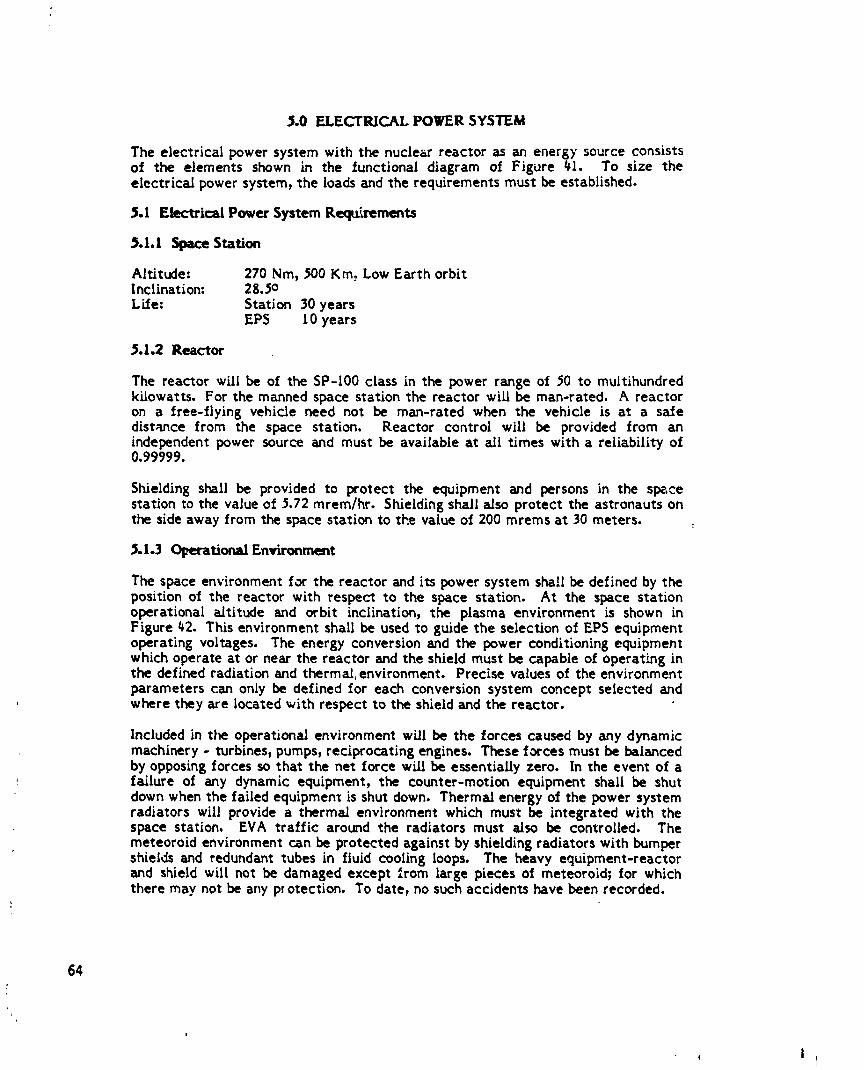
$o0 ELECTRICAL POWER SYSTEM
The electrical power system with the nuclear reactor as an energy source consistsof the elements shown in the functional diagram of Figure 41. To size theelectrical power system, the loads and the requirements must be established.
5.1 Electrical Power System Requirements
5.1.I Space Station
Altitude: 270 Nm, 500 Kin. Low Earth orbitInclination: 28.50Life: Station 30 years
EPS 10 years
5.1.2 Reactor
The reactor will be of the SP-100 class in the power range of 50 to multihundredkilowatts. For the manned space station the reactor wi/l be man-rated. A reactoron a free-flying vehicle need not be man-rated when the vehicle is at a safedist_u_ce from the space station. Reactor control will be provided from anindependent power source and must be available at all times with a reliability of0.99999.
Shielding shall be provided to protect the equipment and persons in the spacestation to the value of 5.72 torero/hr. Shielding shall also protect the astronauts onthe side away from the space station to the value of 200 mrems at 30 meters.
5.1.3 (:)l_---rationalEnvironment
The space environment for the reactor and its power system shall be defined by theposition of the reactor with respect to the space station. At the space stationoperational a/titude and orbit inclination, the plasma environment is shown inFigure ¢2. This environment shall be used to guide the selection of EPS equipmentoperating voltages. The energy conversion and the power conditioning equipmentwhich operate at or near the reactor and the shield must be capable of operating inthe defined radiation and thermal: environment. Precise values of the environmentparameters can only be defined for each conversion system concept selected and
, where they are located with respect to the shield and the reactor.
Included in tim operational environment will be the forces caused by any dynamicmachinery - turbines, pumps, reciprocating engines. These forces must be balancedby opposing forces so that the net force will be essentially zero. In the event of afailure of any dynamic equipment, the counter-motion equipment shall be shutdown when the failed equipment is shut down. Thermal energy of the power systemradiators will provide a thermal environment which must be integrated with thespace station. EVA traffic around the radiators must a/so be controlled. Themeteoroid environment can be protected against by shielding radiators with bumpershields and redundant tubes in fluid cooling loops. The heavy equipment-reactorand shield will not be damaged except from large pieces of meteoroid; for whichthere may not be any pl otection. To date, no such accidents have been recorded.
64
/
1985027415-076
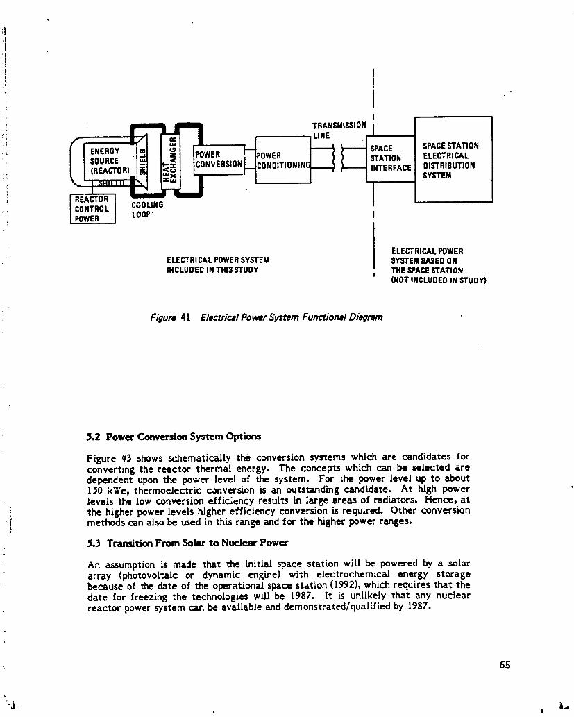
t
.!
! TRANSMISSION;i UNE I
_' _ _ _SPACE SPACESTAT,ON_ ENERGY POWER OWER STATION ELECTRICAL
SOURCE CONVERSION_ uONOITIONIN( INTERFACE DISTRIBUTION:; SYSTEM
COOLINGLOOP"
ELECTRICALPOWERELECTRICAL POWERSYSTEM SYSTEMBASEDONINCLUDED IN THISSTUDY THE SPACESTATION
(NOT INCLUDEDIN STUDY)
Figure 41 Electrical Power System Functional Diagram
2.2 Power Conversion System Options
Figure _3 shows schematically the conversion systems which are candidates forconverting the reactor thermal energy. The concepts which can be selected aredependent upon the power level of the system. For the power level up to about150 kWe, thermoelectric conversion is an outstanding candidate. At high powerlevels the low conversion effic;cncy results in large areas of radiators. Hence, at
i the higher power levels higher efficiency conversion is required. Other conversionmethods can also be used in this range and for the higher power ranges.
2.3 Transition From Solar to Nuclear Power
An assumption is made that the initial space station will be powered by a solararray (photovoltaic or dynamic engine) with electror.hemical energy storagebecause of the date of the operational space station (1992), which requires that thedate for freezing the technologies will be [987. It is unlikely that any nuclearreactor power system can be available and demonstrated/quali/ied by 1987.
65
1985027415-077
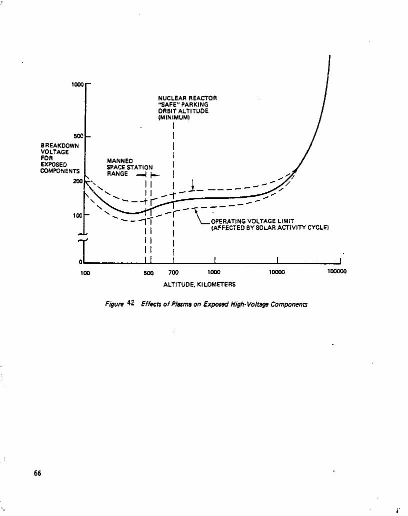
1000
NUCLEAR REACTOR"SAFE" PARKINGORBIT ALTITUDE(MINIMUM)
I5oo I
BREAKDOWN IVOLTAGE IFOR MANNEDEXPOSED SPACESTATION ICOM_NENTS RANGE--4 i"- I
,," 22:.--fT [..
-. " _ --_t" [ .._- _.'- -" "" - "_I'T I OPERATING VOLTAGELIMIT(AFFECTED BY SOLAR ACTIVITY CYCLE)
II I
o_- II III III I I I I
100 500 700 1000 10000 100000
ALTITUDE, KI LOMETERS
Figure 42 Effects of Plasma on Exposed High.Voltage Components
66
"l ,["
1985027415-078

67
' ,, i
1985027415-079
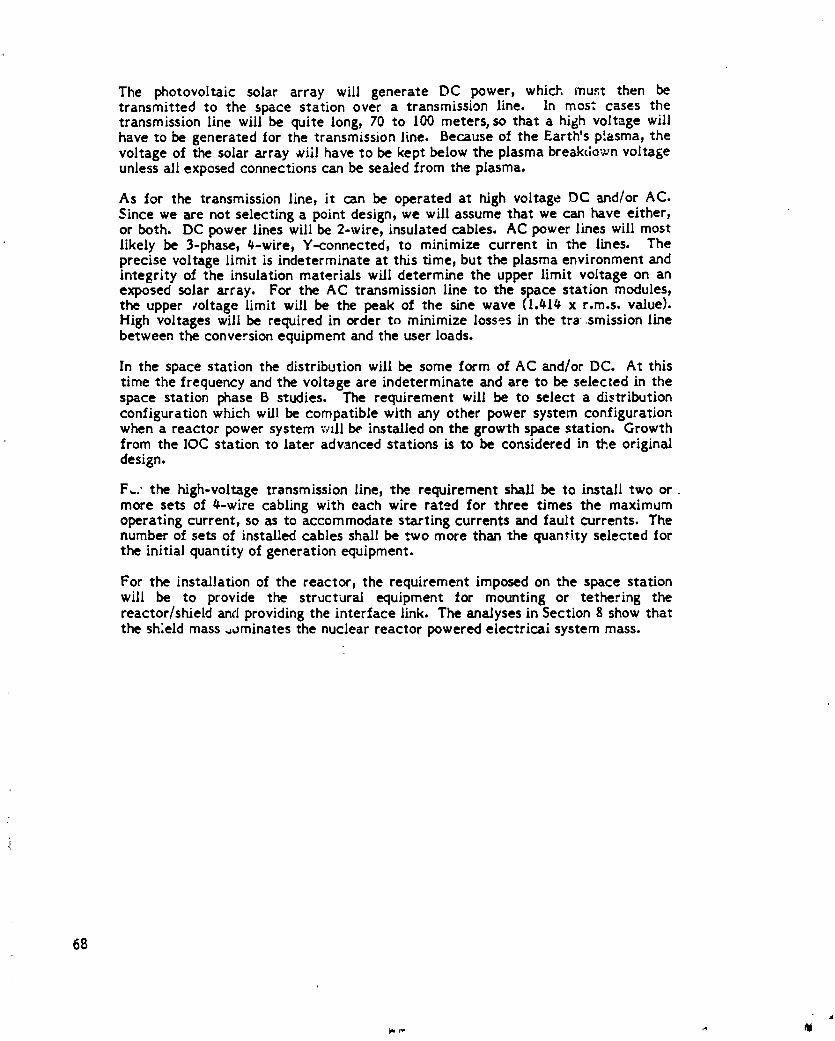
The photovoltalc solar array will generate DC power, which mu_t then betransmitted to the space station over a transmission line. In mos; cases thetransmission line will be quite long, 70 to 100 meters, so that a high voltage willhave to be generated for the transmission line. Because of the Earth's plasma, thevoltage of the solar array _¢iil have to be kept below the plasma break¢;ownvoltageunless all exposed connections can be sealed from the plasma.
As for the transmission line, it can be operated at high voltage DC _nd/or AC.Since we are not selecting a point design, we will assume that we can have either,or both. DC power lines will be 2-wire, insulated cables. AC power lines will mostlikely be 3-phase, _-wire, Y-connected, to minimize current in the lines. Theprecise voltage limit is indeterminate at this time, but the plasma environment andintegrity of the insulation materials will determine the upper limit voltage on anexposed solar array. For the AC transmission line to the space station modules,the upper toltage limit will be the peak of the sine wave (t._l_ x r.m.s, value).High voltages will be required in order to minimize losses in the tra smission linebetween the conversion equipment and the user loads.
In the space station the distribution will be some form of AC and/or DC. At thistime the frequency and the voltage are indeterminate and are to be selected in thespace station phase B studies. The requirement will be to select a distributionconfiguration which will be compatible with any other power system configurationwhen a reactor power system wtll be installed on the growth space station. Growthfrom the IOC station to later advanced stations is to be considered in the originaldesign.
F_.,the high-voltagetransmissionline,the requirementshallbe to installtwo ormore setsof #-wirecablingwith each wire rated for threetimes the maximumoperatingcurrent,so as to accommodate startingcurrentsand faultcurrents.Thenumber of setsof installedcablesshallbe two more than the quantityselectedforthe initialquantityofgenerationequipment.
For the installation of the reactor, the requirement imposed on the space stationwill be to provide the structural equipment for mounting or tethering thereactor/shield and providing the interface link. The analyses in Section 8 show thatthe sh;eld mass _ominates the nuclear reactor powered electrical system mass.
68
1985027415-080

&O NUCLEAR REACTOR-POIrERED SPACE STATION CONFIGURATION OPTIONS
_,n advanced space station with electric_ po_cr needs greater than 100-I_0 kWecan benefit from a nuclear reactor power source. The configuration options forincluding a reactor as the power subsystem for a space station are considered inthis section. The options include attaching the reactor rigidly to the space station;attaching the reactor to a flexible tether; or locating the reactor on a free-flyingspacecraft removed from the spzce staLion. Oower transmission can be achievedb7 electrical conduction, by fuel transport, or by electromagneti,; beaming.Focrt¢_n different configuration options have been investigated, and three wereselected for more detailed t:'ade studies.
6.1 Complete Option Tree
The configuration options can be aztegorized accordingto the location of thereactor and the mechanism by which power is transmitted to the space stal_on.The complete option tree conszdered in this study is shown in Figure t_. Thereactor, shield, power conversion system, and radiator designswere considered on ageneric basis in rJ_s preliminary a_sessment, i.e. genera[ system advantages anddisadvantages were investigated rather than focussing on subsystem designs. Thepower level was also not defined in thLs systems assessment, but a value betweenI00 kWe and 300 kWe was implicitly assumed.
Reactors which are rigidly attached to the space station can be located either inthe space station itself or on a boom. The space station electrical power can bedrawn from t,_e nuclear power system either directly through conducting wires orindirectly as in a regenerative fuel cell. The indirect case consists of anelectrolysis plant located with the reactor and fuel ceils located with the spacestation. Fuel cell reacta;;_ would be pumped through fluid pipes located in theboom structure to the fuel cells, with a return line pumping the reaction productback to the electrolysis plant.
IA U 3J)Ol_lOdkRO Tll"lqOqlO IIR811RiJA_'t1_i RIIA_r_ _LYIR
I '! I 'i I I I[t.s t.lt 1.1 1• 2.1 3.1 lIJ
_ _ MICI_Vll TANKJER OD,,,ONIITiliQ NIaN
l .m. t
I' ' 1 J I
!,,?,.1 1.1.1
¢IOON_'_rOR _ • 3.t ,t _L,• Z.ll.I s0-IIlJlaqONMVI TAliCK|R l,AdlJlq T,i_llrdIR
I 1 1 I ,lLl,v _.1=1 2.13 _.t,_l J
I 1.1¢11 I_ed_ PI,,MiQ T_ IgAVllt_/IOll I[ 1
_1,_.I.1 3.1.1•
I_c_r
Figure 44 Reacror-S_aceStar Configuration Options
69
1
1985027415-081

Reactors which are attacned to the space station with a long_ flexible connectionare tethered reactors. Power transmission can be either along the tether or
_, through free space, The tether can be electnc_,ily conducting with reactor-generated electricit) transmitted through the tether. With an electrolysis plantlocated with the reactor, the reactants can be transferred either continuouslytLrough fle×ible hoses or with a batch process using ttnks transported either alongthe tether or through space by an OMV or an OTV. Electricity generated at thereactor can also be converted to electromagnetic energy =..3 beamed to the spacestation, either through free space or through a waveguide.
Free-flying reactors can be either in the same orbit (co-orbiting) as the space" station or in a higher orbit, if the reactor is co-orbiting, power can be transferred
either by microwave beaming or by fuel tanke:s. If the reactor is in a higher orbit,then the reaCor and space station are not always nearby each other. A tanker capstill be us,,_ to transport fuel ceil reactants and reaction products back and £orth,but for e_._tromagnetic beaming the vehicJes must be in line with each other.Laser power transmission can be used in conjunction with an energy storage deviceor with reJav satellites. If beaming is only done when the reactor and space stationare in direct line of sight, then energy must be stored for use when the earthoccults the direct pa¢h. With _ sufficient number of relay mtellites, light can bebeamed continuously from th,. reactor to the space station.
&Z On-B,0_rd Reactor Power System _.Jecidon
The most straightforward configuration option L_that where the electrical pow_c isgenerated near where it is to be distributed. This option p:_ces the reactor on thespace station with sufficient shielding to protect space station personnel to sa._eradiation dose rates for continuous residence at the space station. This optio_ is :referred to as the .,ubmarJne option because of it._ similarity to a nuclear pe,verplant on z manned s,somarine.
This concept is illustrated in F.;guLe45. The reactor, power conversion system9 andshield &re located on the space ._tatJon, with the radiator somewhat removed fromthe station. A 100 kWe space ,eactor w_L' reject from 300 to 2000 kW of heat at
temperature., in excess of 55¢) K, with oetails dependent on the 2Dowel conversionefficiency. This heat will be f_jected by radiation from _0-80 m of raJiators. Toprevent excess heating of the space station and astronauts performingextravehicular activities, the radiator m_'st be removed to some d'_tance from thespace station, probably 30 meters or r,_oreaway.
This approach requires pumping of a heat transfer fluid from the reactor to theseparated radiator. It al;o has the heaviest shield r.,ass of all the optio,_sco,_sJdered,since the shielding must protect people residinfs in close lxoxin;ity on acontinuous basis. The shield mas_ required to reciuce the radia _ondose rate to5.7 torero/hour a_ a distance of 3 meters from the reactor in all directions is about35-45 tonnes, d_pending on power level and conversion system.
On the poshive side, this approach allows the mos° flexibility in space stationattitude, since there is no don_inant inertia moment. It ;,as a ver_ high ballisticcoefficient, requiring a m!nJmum of orbital makeup propulsion. This con,Sigurationalso a!!ows a wide envelope of EVA operations except near the radiator. Thisenvelope is not constrained in any direction by ionizing radiation !evcls. The or,,lyEVA constraint is that due to thermal exposure near the rad:'tors. This option
7O
"l
1985027415-082

.1 ORIGINALPAGE IS
' OF POOR OUALITY REACTORRAmATOn
Figure 45 Reactur Near Space St6tion CG [ 'Submarine' Concept)
provides good opportunity for m_nned mai_,tenance of the reactor system if Satrequirement is des;'ed.
The shield ma_ c_n be reduced significantly by placing the r_actor on a boomattacned to the _pace station, as shown in ._;gure #6. Rather Lnan shielding forcontinuous manned presence close to the reactor in all directions, this option
" reqtJres shielding _or lirr ited exposure periods in a!l directions near the reactor _dcontinuous e.xposure only on the space station, which is removed to some distanceaway from the reactor. This ceduces the shield mass depending on dist&_ce, power
Jl_ leve!, and convcrsi_)_t ._ystem. This o2tio:, also places the radiator neat- the heatsource, r_ducia_ th_ p_-,ed1"0pump heat.
71
i
1985027415-083

REACTOR
OMV
(MAY BE POSITIONED AT
EITHER END OF BOOM)
Figure 46 Reactor on Boom
The power conversion system is located at the reactor end of the boom.Electricity can be used to electrolyze fuel ceil reactants, which are then pumpedto fuel cells on the space station, or transmitted directly to the space stationelectrica_ power distribution system through conducting wires. If the fuel ceiloption is used, the reactor must provide enough electrical power to make up forelectrolysis, pumping, and fuel cell ineffidencies, i.e.
LPe- - + FpumpingPo = - qeR, rIFc
where Pe is the electrical power demand at the space station,
Ppumping is the power required to pump the fuel,
Po _sthe reactor electrical output power,
rle£ is the electrolysis e_ficiency, and
rlFc is the fuel cell efficiency.
Current capabilities for a regenerative fuel cell syst=m efficiency are 60-66%(ref. 16) fo, a hydrogen/oxygen system. Hydrogen/halogen regenerative fuel celtsystems might boost the system ef,_iciency still further, perhaps to g0-90%.Ignoring pumping losses, the reactor output must be 11-67% higher than space..ration demand for the fuel cell option. Electrical conduction, hov,ever, wouldrequire an excess power of less than _%.
72
1985027415-084

The boom-mounted reactor option achieves its mass savings b) restrictingpersonnel access around the reactor, allowing lighter shielding. Exclusion zonesare therefore introduced within which EVA and orbiter traffic is restricted tolimited duration. This might affect reactor maintainability if the design requires
: manned maintenance. The boom-mounted reactor also introduces a preferredspace station attitude. The large mass at the end of a long boom wiU drive thesystem toward a highly stable gravity gradient mode.
The relative advantages and disadvantages of the three on-board reactorconfiguration options are summarized in Figure _7. The submarine option, with thereactor on the space station, requires the heaviest shield and must utilize somemeans of transporting waste heat to the remote radiator. The boom-mountedsystems have lighter shields and do not require remote heat rejection. Of the twoboom-mounted systems, the conducting transmission line option requires the leastreactor power, so it was judged preferable to the fluid pipe option. Since thetechnology for electrical transmission is more straightforward than that for heattransfer over 60-70 meters length in space, the conducting transmission line wasselected as the preferred option for detailed trade studies.
Figure 47 On-Board Reactor Option=
Configuration Advantages DisadvmntaguI I
1.1 Submarine ,,Good attitudeflexibility e35-45 tonneshieldmm=eM_ned maintainability eNeedfor separatedradiator• Goodtraffic acc==ibility• Minimumtranra_i_=iondistance
1.2.1 Conducting • 12-20tonne$hieldmass • Traffic restrictionsTnm_i_,on • Radiatornearheatsource • AttJu_le limitation=Line= • Needfor powertransmi_ion
1_ FluidPipe • 12-20tonnechisldmass • Traffic restrictiom• Radiatornearheat=ource • Attitude limitations
' • 11-67%Dowerlosses
_._ Teth_ed Reactor Power System Selection
The tethered reactor power system option is shown generically in Figure _8. Thereactor is located at one end of a long, flexible tether _nd the space station islocated at the other end. Dynamic stability considerations wilt likely dictate thatthe tether be vertical, with the reactor above the space ¢"tion. Powertransmission is by conduction, fuel transfer, or electromagnetic beaming.
The advantages and disadvantages of tethered reactor= in general vis-a-vis on-board reactors are summarized in Figure _9. The shield mass will be discussed indetail in Section 6._ below. As expected, the mass d_creases steadily with tetherlength. For a ma_-rated shield, this thieid mass decreases only asymptotically
73
#
L ......
1985027415-085

RAr
REACTOR
Ir' UID HOSE
D-OF-LIFE DISPOSAL
Figure 48 Tethered Reactor
Fi_,-',-,_9 Tether•dRew'mr Characteristics
Advan_ DimdvantMlsI I I III I I I I m I
eOlcnlued shield rml eShkDId m_m mymptotic beyond 60 metro"
• Distantradiator • GrwKltional forms"- O (0.06/_Q/m)
• RIducId traffic conltnlirrtl eSinqll point fIilurl fTom tether break
• ObviItm perigee kick
for longteff_rl
74
1985027415-086

beyond 60 meters. That is, the man-rated shield mass decreases to an asymptoticvalue with distance which it reaches at about 60 meters and no benefit can begained in reducing the shield mass by increasing the tether length beyond thisdistance.
The next threshold for tether length occurs at about 25-30 kilometers. This occurswhen the gravity gradient induced tension in the tether would impart an impulse tothe reactor if the tether were severed. This impulse places the reactor in atransfer orbit with the same perigee as the initial reactor circular orbit and a;apogee which is seven times farther from the system center of _ravity than theperigee. For example, if the space station were originall • _na 500 km high circularorbit and the tether length were 30 ksn with a system center of gravity at 50_ kin,a tether break would transfer the reactor from its original 530 km circular orbit toan elliptical orbit with perigee at 530 km and apogee at 680 kin. Thus_the tensionin the tether could obviate the need for a perigee kick stage when placing thereactor in a long-lived orbit.
A long tether with a length of more than a kilometer would simplify the concern ofthermal radiation to the space station, orbiter, or EVA astronauts. Trafficcon._traints would also be relaxed, since the space station and most traffic patternsare out of the ionizing and thermal radiation fields.
One drawback to a long tether is the acceleration on the space station. Thereactor-space station system will travel in an orbit corresponding to a balance offorces at the system center of gravity. Pseudogravitational for-es will occur at allother locations, since the gravitational and centrifugal forces will not cancel. Thestrength of these forces is about 9.5 x t0 -6 m/s 2 for each meter away from thecenter of gravity, or 50 micro-g's per kilometer. Many of the reference spacestation missions requ=.remicrogravity conditions for materials processir,g. While itis not yet well-known what level of acceleration is acceptable to complete thesemissions, it is believed that g-levels between 10-Sg and 10-3g may be required. Ifthe missions are sensitive to t0-Sg (10 -# mLs2), then a tether length of 200 metersor more would perturb the mission. If 1_-_g is allowed, then 20 kilometer tetl-_rswould be acceptable.
Power from the reactor can be transmitted to the space station by a condur.tingtether. This is essentially the same configuration as that selected above forfurther analysis as an on-board reactor_ and will not be considered again here sincewe wish to select one of each type of concept for analysis.
The reactor power system can also have an electrolysis plant associated with it,and fuel cells on the space station. This is shown schematically in Figures 50 and
, 51. the fuel ceil reactants have a high systems synergism Lf H2-O 2 fuel cells areused: the reactor would then provide oxygen for life support systems, hydrogen forstationkeeping propellant, and perhaps fuel for cryogenic orbital transfer vehicles.In this study the analysis did not include additional power for serving the integratedsystems. The reactant flow rate required for 100 kWe is 8-10 gm/s for fuel cellef_iciencies of 60-80%. Assuming a regenerative fuel cell system efficiency of60-75%, the reactor output power must be 1/3 to 2/3 hiooherthan the load requiredat the space station.
The reactants can be carried to the space station either through hoses on acontinuous basis, with hydrogen and oxyg_.n gas flowing to the space station andwater returning to the reactor, or with free-flying tankers carrying liquid fuels
75
I
1985027415-087

' _rI/3-2/3 LARGER i RADIATOR.
NEED I/3-2/3 MORE POWER __ADDED MASS
FOR ELECTROLYSIS IELECTROLYZER
�TANKAGEj
i r/ELEC.ELEC ,v 60--75%
I
} .zo , o= "2 ;.- 74kCa./kw,I
I
j.21
L
l
q
Figure 50 Fluid HoseTenet
- RADIATOR !i
_ | j
I ELECTROLYSIS
LIOUIFIER| i i
OR 21 DAYS
76 Figure5I Tethered Tanker
I
L
1985027415-088

both ways. The tanker option requires a liquefaction plant at the reactor andinvolves substantial traffic of the fuel tankers, while the hose option requiresneither. The hoses might be more vulnerable to meteoroid impact. In each case,additional mass must be placed in orbit for the electrolyzer, fuel ceils, and hoses ortankers.
i[ A variation on this option is one where the fuel is carried in tanks which travel, along the tether. This is referred to as the clothesline option, with the hydrogen
and oxygen moving along the tether to the space station and the water moving toI the reactor. This is essentially the same as the tanker option, except that the
tankers are attached to the tether.
Power can also be transmitted to the space station in the form of microwave' beams. Figures 52 and 53 illustrate two forms of microwave beaming. A klystront at the reactor generates microwaves which are transmitted to the space station,
either through a waveguide or through free space. In the free space beaming case,the output power required at the reactor is:-|
PePo.=
rldc-rfrltransrlrf-dct
where rldc-rf is the Idystronefficiency,includingthe waveguide feed and thenear-fieldlosses,
rltransis the transmissionefficiency,accounting for path loss andspHlover,
rlrf-dcistheantennaefficiency,includingrf-dcconversionand rectennaheatinglosses.
Inthe.waveguidecase,thereactoroutputpower is:
10uL
Po = qdc-rf rlrf-dcPe
where IJ isthewaveguideattenuatiorcoefficient,
L isthewaveguidelength.
Klystron efficiencies of 3)% have been measured_ and optimis:ic projectionsestimate efficiencies of 70% may be c,_ssible. Antenna efficiencies are likely to beabout 50%, but optimistic project! • may place this value as high as 90%.Waveguide attenuation coefficients between 0.01 and 0.03 decibels per meter seemlikely, while beam losses of 20-40% are ro.asonable for S-band (3GHz) transmission
. i through kilometer distances. Thus, the range of reactor output required to deliver
I I00 kWe to the space station for the free space microwave beaming option is200-950 kWe. For a one kilometer waveguide tether, reactor outputs of1.6 MWe-600 MWe are required.
The relative advantages and disadvantages ol the five tethered reactorconfiguration options are summarized in Figure 5_. The microwave options requireconsiderable excess reactor power to compensate _or system losses: at least afactor of three for Idystron and antenna efficiency and another factor of ten forwaveguide attenuation. The two tanker options require a liquefaction plant andtanker vehicles. The liquefaction plant would be a major power drain and wouldrequire a substantial development program to enhance the system lifetime.
77
1985027415-089

'_ _ r/ELEC.tf "- 35-70%
I KLYSTRON I
"-10 cm WAVEGUIDE1 k4/m
ATTENUATtON•"0.01--0.O3 dblm
nrf-dc " 5o-eo%
Figure 5Z Waveguide Tether
RADIATOR
REACTOR
ttdc.rf "- 35--70%
KI.YSTRON
MICROWAVETRANSMITTER
L20-.44_ BEAM LOSS
OtOrtm2) _ 200 L (kin)FOR S-BAND(3 GHxJ
T/rf.dc"50--70% ANTENNAi SPACE STATION
! 78 Figure 53 Microv_ve Beam Tether
1985027415-090
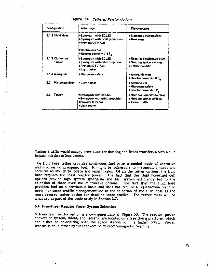
Figure 54 Tethered Reactor Options
Configuration Advamages DisadvsntagesII I
2.1.2 Fluid How eSynergl_ with ECLSS e Meteoroid vulnerability• Synergimnwith orbit propulsion • Hose mass• ProvidesOTV fuel
=
• Continuous fuel
• Reactor power " 1.4 Pe
2.1.3 Clothesline •$ynergir_m with ECLSS eNeed for licluifaction plantTanker •Synergism with orbit propulsion •Need for tanker vehicles
• ProvidesOTV fuel • Tether stabilit,/• Light tether
2.1,4 Way•guide • Microwave safety •Way•guide mm
• Reactor power ;) 30 Pe2.2 Microwave Beam • Light tether •Antenna siz8
• Microwave safety
• Reactor power ;) 3 Pe2.3 Tanker ieSynerglam with ECLSS eNNd for liquifsction plant
!•Synergism with orbit propulsior, • Need for tanker vehicles• ProvidesOTV fuel • Tanker traffic• Light tether
Tanker traffic would occupy crew time for docking and fluids transfer, which wouldimpact mission effectiveness.
The fluid hose tether provides continuous fuel in an untended mode of operationand involves no cryogenic _ueL It might be vulnerable to meteoroid impact andrequires an ability to locate and repa;: leaks. Of all the tether options, the fluidhose requires the least reactor power. The lact that the fluid hose/'_uel celloptions provide high system synergism and fair system elficiency led to theselection of these over the microwave options. The fact that the fluid hoseprovides fuel on a continuous basis and does not require a liquefaction plant orcrew-monitored traffic management led to the selection of the fluid hose as themost favored tether option for detailed trade studies. The tether mass will beanalyzed as part of the trade study in Section 8.7.
6,_ Free-Flyer Reactor Power System Selection
A free-flyer reactor option is shown generically in Figure _5. The reactor, powerconversion system, shield, and radiator are located on a free flying platform, whichcan either be co-orbiting with the space station or in a higher orbit. Powertransmission is either by fuel tankers or by electromagnetic beaming.
79
|
1985027415-091
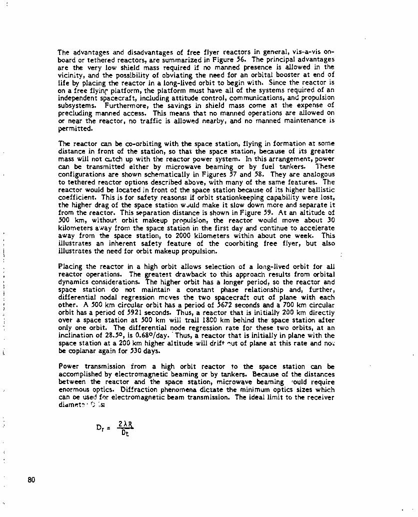
The advantagesand disadvantagesof freeflyerreactorsin general9vis-a-vison-boardor tetheredreactors,are summarized inFigure56. The principaladvantagesare the very low shieldmass requiredif no manned presence isallowed in thevicinity,and the possibilityof obviatingthe need foran orbitalboosterat end oflifeby placingthe reactorin a long-livedorbitto beginwith. Sincethe reactorison a freeflying'platform,the platformmust have allof the systemsrequiredof anindependentspacecraft,includingattitudecontrol,communications,and propulsionsubsystems. Furthermore,the savingsin shieldmass come at the expense ofprecludingmanned access. This means thatno manned operationsare allowedonor near the reactor,no trafficisallowednearby,and no manned maintenanceispermitted.
The reactorcan be co-orbitingwith the spacestation,flyinginformationat somedistancein frontof the statJon_so thatthe space station_because of itsgreatermass willnotc_tch up with the reactorpower system. In thisarrangement_powercan be transmittedeitherby microwave beaming or by fuel tankers. Theseconfigurationsare shown schematicallyinFigures57 and 58. They are analogousto tetheredreactoroptionsdescribedabove,withmany of the same features.Thereactorwould be locatedinfrontof thespacestationbecauseof itshigherballisticcoefficient.Thisisforsafetyreasons:iforbitstatJonkeepingcapabilitywere lost,the higherdrag of the spacestationw_uld make itslow down more and separateitfrom thereactor.Thisseparationdistanceisshown inFigure59. At an altitudeof500 kin,without orbit makeup propuls;on,the reactor would move about 30kilometersa'#ayfrom the spacestationinthe firstday and continueto accelerateaway from the space station,to 2000 kilometerswithinabout one week. Thisillustratesan inherentsafety feature of the coorbitingfree flyer,but _Iso
i illustrates the need for orbit makeup propulsion.=,
Placing the reactor in a high orbit allows selection of a lo_g-lived orbit for allreactor operations. The greatest drawback to this approach results from orbitaldynamics considerations. The higher orbit has a longer period, so the reactor andspace station do not maintain a constant phase relationship and, further,differential nodal regression mc,ves the two spacecraft out of plane with eachother. A 500 km drcular orbit has a period of 5672 seconds and a 700 km circularorbit has a period of 592t seconds. Thus, a reactor that is initially 200 km directlyover a space station at _00 km will tredl 1800 km behind the space station _fteronly one orbit. The differential node regression rate for these two orbits, at aninclination of 28.5o, is 0.6go/day. Thus, a reactor that is initially in plane with thespace station at a 200 km higher altitude will drift _ut of plane at this rate and no;be coptanar aga_.nfor 530 days.
Power transmission from a high orbit reactor to the space station can beaccomplished by electromagnetic beaming or by tankers. Because of the distancesbetween the reactor and the space station, microwave beaming ,ould requireenormous optics. Dif._raction phenomena dictate the minimum optics sizes whichcan De usedfor electromagnetic beam transmission. The ideal limit to the receiverdiamet_" r_ :s_
Dr : 2_ROt
8O
1985027415-092
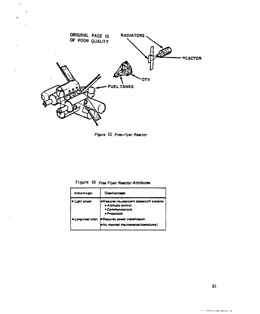
ORIGINAL PAGE IS RADIATORS
OF POOR QUALITY '_ _,._
_£ACTOR
FUELTA_KI OTV
Figure 55 Free.Flyer Reactor
Figure $6 Free Flyer ReacrorArtT(butu
Advamaget Disa_lvsrtlmgmI I I
• Light shield oReclUim in_l=mK_nt spao_n_• Atti_x:Jo control• Communcations
• Propulsion
• LoJ_lived orbit oRwuirtus power tnlmmiet, on
BNo rearmed mmmt_to_ratiom[
81
1985027415-093
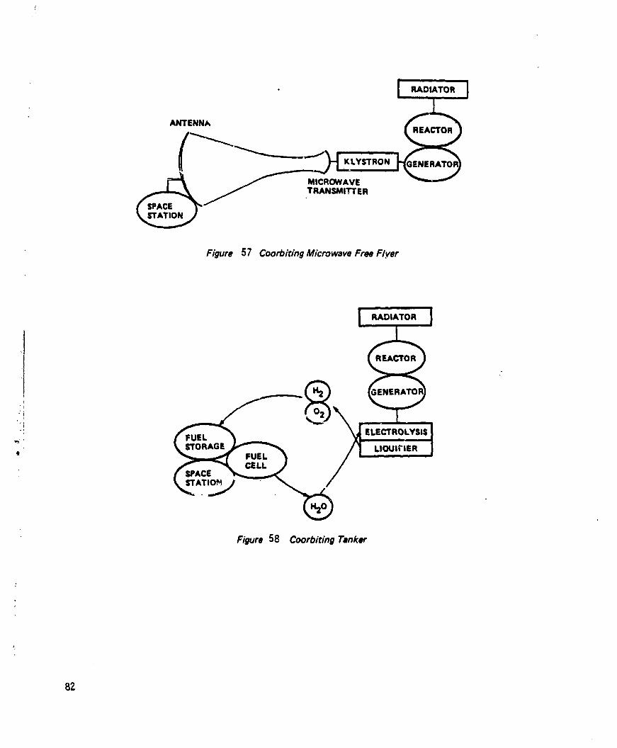
RADIATOR
ANTENNAREACTOR
KLYSTRON
MICROWAVETRANSMI .'!"rER
SPACESTATION
Figure 57 Coorbiting Microwave Free F/yer
RADIATOR
REACTOR
°'i
_'[ ELECTROLYSISFUEL
"_" STORAGE LIOUIFIER* FUEL
CELLSPACE
Figure 58 Coorbiting Tanker
82
1985027415-094

33
1985027415-095

where _k is the beam frequency,
R is the distance from the transmitter to the recei'-er,
Dt is the transmission aperture diar.,,eter.
Microwave wavelengths _e I-I0 cm. This means that the minimum size _._rmicrowave antennae &nd transmitters must be about 100-300m if beaming is dcneonly when the spacecraft are close, and 30G-1000m if beami._g is done wheneverthey are in line of sight. This large size, and the impact it would have on spacestation missions and design, dictate the use ci shorter wavelengths. A laser with awavelength of 0.._ m wvuld require transmitter/receiver ape-tures ot severalmeters. Laser transmission was considered as the only feasible spectral band forthis study.
The laser can only { _ power to the space station directly when the station is notocculted by the earth, i.e. only when the direct line of sight frcm the reactor tothe space st:_tion does not intersect the earth. If the two spacecraft aze in planeat 5G0 I<m and 700 kin, the viewing opl_ortunities last for 9.0 hours out of every37.3 hours, as shown in Figure 60. In this tiguce, the bars represent times when tt;espace st3tion is visible from the reactor. The rest oI tl-e time, the)" are occu]t_dby the earth. Figure 61 shows the azimuth and range when " e two are in directline ef sight. These figures become more compie_ when the space_raIt are not r.coplanar orbits.
The spar- station requires a steady power source. Laser tx_ver _aramissitherefore requires e_:ber high power during periods of geod viewing_ corabmed with.energy storage on the space station, or i, system of laser relay satellites. Yhelatter was not investigated in this study because it would require a large r.Jmber ofmirrors with extremely high pointing precision. Figure (;2 illustrates the fc.-merconcept. The reactor output power must be sufficient to compensate for ;a._er andreceiver inefficiencies. It must sati_fy-
PeP0 =
qe-L qL-e VF
where qe.Lis the eJect,ic-to-i_ht 'a=e," efficiency,
rlL-e is the light-to-electrir efficiency of the .'eceive,,
VF is th_ view factor.L
Typical high power continuo,,s wave laser efficiencies , "e ur_der I%. Thetheoretically achievable efIicie)tcy might be as high as #0%. jurren1: pbo _voltaicreceiver efficiencies are around 15-18%, but some concentrator desxgner_ predictefiiciencies up to 35%. For a 10q kWe space station, the reactor output powermust therefore be around 1 GWe h current technolo&y, az_deven with optimistictechn¢,iogy aLvances .he reactor output power m_'st be about 3-20 _We.
The high orbit free flyer reactor option is shown in F.6ure 63. The reactor has anelectrolysis and liquefaction plant, and the sp_ce station h=s a fuel cell. L:.quidhydrogen and ,xygen are sto.'e_ in tanks at the reactor which are carried to thespace statio;'_ with an orbital transfer vehic'e. The OTV carries water to thereactor on the return trip. Since= the propellant required for [arEe plane change'., is
84
1985027415-096

HilrATION - BOOIra,
HFIIEE FLYER m700 km
ill., 0t
N7 ,rl I-, - /m " I n _ " -
NOTVISIBLE o i tk lkTIME. Ii0_1
Figure 60 High Orbit Free Fiver Viewing Factor
ii •
RANGE,N.MI.
Figure 61 Relative Free Flyer Po_i'.ion
1985027415-097
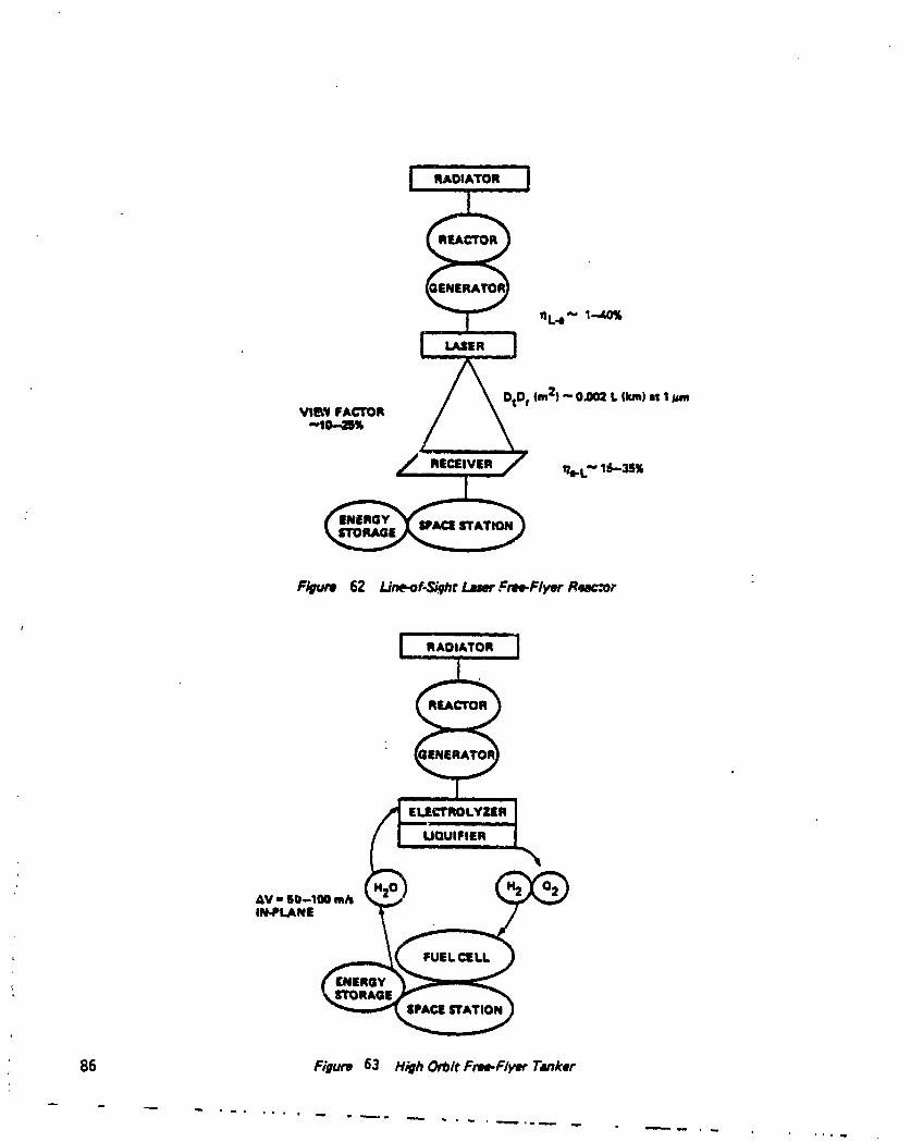
RADIATOR
REACTOR
ENERGY PACES'rATIONSTORAGE
F/gum 62 l,'ne-of.Si_qh¢_ Fme.Flyer R_mccor
RADIATOR
REACTOR
ELECTRO LYZIR
UQUIFIER
FUEL CELL
STORAGESPACE STATION
86 Figure 63 High Or#it Fnm.Flyer Tsnker
1985027415-098

I very large, t.he frequency with which the reactor and sp_ce station becomei coplanar determines the launch frequency and therefore the storage and payload
mass. The orbital transfer V and the payload mass determines the propellantrequirements. These will be discussedquantitatively in Section $.7.
I
The advantages and disadvantages of each of the free flyer optior_sare summarizedin Figure 64. The coorbiting options offer the same features as their tetheredanalogs, with the added complexities associated with the independent spacecraftsystems, i.e. the tethered microwave option seems more attractive than thecoorbiting microwave option and the coorbiting tanker offers no advantages overthe tethered tanker. For the high orbit options, the lasers require extremely highreactor power. Therefore, the high orbit free flyer tanker was selected a_ themost attractive free flyer option.
Mission Sensitivity
One configuration from each general class was selected for a detailed trade study.These are indicated in Figure 65: one on-board reactor option, one tethered reactoroption, and one free flyer option. The on-board option consists of a boom-mountedreactor with conducting wires to the space station. The tethered and free flyerreactors use reactor power to electrolyze water to H2 and C2 which are used infuel cells at the station; the tether supplie_ continuous fuel and the free flyerdelivers it in discrete batches. Two of the options place the reactor in a short-lived orbit and the free flyer is in a long-lived orbit. The microwave and laserbeam options were not considered further, primarily because of the excess reactorpower required to compensate for beam generation and conversion inefficiencies.
Any design configuration selected must be capable of performing the missionsdescribed in Section 2t above. It must provide power to the space station in the100-300 kWe range, largely for materials processing missions. It must permit goodviewing for astronomy and earth observation missions. It must allowextravehicular activity with considerable freedom of motion for space-basedassembly and maintenance. It should not be subject to large accelerations whichwould jeopardize microgravity quality for materials processing. The constraintsimposed on vehicular traffic and the frequency and magnitude of dockingdisturbances should _e minimal. Finally, since crew size is limited and their timeis valuable for mission performance, the power system should not require largeamounts of crew time.
Figure 66 summarizes the potential impacts of the nuclear power system on spacestation attributes affecting mission Performance. All three systems are readilyscaleable in power level in the range from i00 to 300 kWe and above. All threehave low drag and minimum control complexities when compared with solar powersystems. The nuclear reactor power systems do not interfere with viewing in any
direction, e_cept for the boom-mounted reactor which only blocks a very smallarea (u_10- steradians, mostly due to the radiator). The free flyer reactor allowsthe space station complete flexibility to select the attitude, while the tether andboom-mounted configurations will have a strong gravity gradient moment.
The boom-mounted and tethered reactor shields are designed to redure radiationlevels at the space station to acceptable levels for habitation with higher radiationdose levels for short periods in areas away from the space station. This willintroduce some restrictions to traffic near the reactor_ but these are minimal bydesigr_. The thermal output of the radiator at high temperature will litnit
87
t
1985027415-099

ORIGINAL PAGE ISOF POOR QUALITY
F_gure64 Free-Fl_r R_ctor ODtions
Configuration Advont_m ObodventalmI III I I
3.1.1 Co_)rbidngMicmm • Fixedmactor-lmltion JM_ siftWBelrnir_ orientltion _Viewinglnterflnmce
• Fixedspacingwith RCS =Oiffenmtlaldl_i=Anli_ t_
,_=_,=rpower;)3Pebendof Ilk disposal
3.1.2 Co-orbitingTanker • LowAV DTinktr1111_1_¢• FlexibleItltJon Ittitudl DNeedfor liquiflctionpllnt• Sylt_n synergim_ ,Nmd for rankervehida
3.2.1.1 Line-of-SightLI_ • inherentlysafedisl_l DNmdfor morgystorage• No fuelstorage DPotntingc=mplexiw
qjsir hm=_ls,Rimctorpower;>20 MWe
3.2.1.2 I.Imrs With Relay= • inherentlyraft dilpoul _$ylrmmoompklxities• No fuels_omg_ _Spemcreftnumber4rNoeneqWstorage
3.2.2 HighOrbitTsnker • Inhlmmtlysift dilposiI pOrbitcomplexity• SystemWnergikm ,Prolllllnt loll• Modm Wst_ effi_e_ oln_hmClUem_ otx_ormnkim
eNNd forIk:luiflctionplln• Needfor tinker vlhickll
1,1 ILl Um m
,_ I I l* "J " _ t I 'i
'- ! I1,1.1 1.1.11•
Illll_mVl Tamwll
Lt.I M3 1Md
TNI_IIt lm_nlewum
r iI.,1.1.1 I,LI JI
tme4m, ltllat_
Figure 65 R_cror-$pace Station Configuration Selection
88
w
1985027415-100

extravehicular access in the vicinity, which constrains extravehicular activitywithin some exclusion volume near the boom uounted reactor. There are no EVAconstraints on the space station missions in the free flyer configurations, and onlythe obvious traffic restricton of avoiding collision with the tether in the tetheredreactor case.
Microsravity qt_iity is very high in both the boom-mounted and free flyer cases.The tethered reactor wc ld induce an acceleration on the space station on theorder of 0.01 m/s2 (1 mLLti-g). Th_s m(ght adversely impact materials processingmissions. If it does, then other designs would have to be considered, such aslocating materials processing facilities at the center of gravity along the tether orproviding a counter balance below the space station to move the center of gravitydown to the station.
The free flyer" reactor will have tanker tr&ffic between the reactor and the spacestation ferrying fuel back and forth. This will cause docking disturbances and willoccupy crew time in rendezvous, docking, fuel transfer, and return. There will alsobe additonal orbiter tr_fic and docking to provide OTV propellant for the tanker.The OTV wUl also likely require periodic servicing at the space station, further
L_ occupying crew time. There will be no docking disturbances or crew time
) essoclated with the boom-mounted or tethered reactor options.
t
, , i i i ii
Nuclear Space Stsdon Conf'qFu'ation Concept
Potential Impact of ' vNuclear Power System On.Board Tethered I Free Fl.er
i | ii v /
Powerscalability Y_s Yes
DraS Low iLow. Low
View blocka|e Low None None
Attitude flexibilit7 Preferred attitude Prefers_.d attitude Flexible
Traffic comtra/nts Minimal Mininud None
iii EVA constraints Some None NoneMicrognwiU quality Eli_ Medium Hip
Docgin| disturbances None None Some
Crew time None INone Some,, is
FtguPe 66 Summary of Pomntlal Iml_crs on Missions
89
, m .
1985027415-101

ir
|
7.0 REACTOR AND ELECTRICAL POWER SYSTEMS
This section of the report summarizes the evaluations performed on the reactorand electric power generation subsystems in assessingthe applicability of nuclearpower systems for manned space stations. The section is organized with initialsubsections discussing the major components of a nuclear powe, system, namely,the reactor, the shield, and the power conversion subsystems. These are followedby a presentation of parametric weight data for a range of power levels, shieldconfigura_ons and power conversion subsystem options. Data and sketches arepresented for specific power system-space station arrangements and for alternatehigher powered system arrangements. A separate report section discussessystemoperational and reliability characteristics in general terms. The final sectionsummarizes the conclusions reached on the characteristics of nuclear powersystems for the space station application.
The goals of the study were to examine three operational locations for the nuclearpower system: on-board the space station or closely attached to it with a boom,tethered but at a long distance (-30 kilometers) from the station, and as a freeflyer. To aid in this examination, parametric mass information and layout sketchesof power systems operating in the power range of 100 to 200 kWe of net electricalpower and using dynamic and static conversion cycles were to be determined. Anunderlying assumption in the studies was that the reactor and power conversionsystems would be close derivatives of 5P-100 technology since the development ofa different nuclear power system specifically for the space station application isunlikely to happen. Two specific power systems were _.ssumedfor the comparisonso_ the boom-mounted, tethered and free flying configurations: a baselinethermoelectric power system developing 1_0 kWe of power, and a 300 kWe systemutilizing an advanced dynamic conversion cycle with essentially the same reactor.Operational characteristics were to be determined as well as dimensional and massestimates.
The study approach included on evaluating the relative mass characteristics ofalternative nuclear power system concepts. Since the shield component is themajor weight item in manned applications of nuclear power systems, design aspectsthat significantly influenced the shield design and mass were of primary concern.Those aspects include the geometric configuration of the shield, the allowable doserates from the reactor, and the size and efficiency of the power conversionconcept. Four shield geometries were originally considered, designated as four-i_i,two-pi, conical, and shaped four-pi configuraHons. The form of the fourgeometries is shown in the sketches in Figure (;7 which also depicts a generaJ,close-coupled arrangement of the power system and space be_e. An indication ofthe relative masses of the shield geometries and their relative areas of doseprotection can be envisioned from Figure 67.
Dose rate limitations from the reactor were assumed at two locations: at the spacestation proper and at a 30 meter distance from the four-pi shield. The reactor doserequirements were assumed to be one half of the total aJlowable dose.
The effects of power conversion type on shield size and weight were determined asa function of three conversion systems! one dynamic, one static, and a baselinethermoelectric conversion system. The generic dynamic and static conversion
i systems were synthesized from characteristics of specific systems. A discussionofthe power systems evaluated and their characteristics of interest is given inSection 7.2.
90
1985027415-102

STATION GEOMETRY
POWERUNIT __.___
t
i • J i i ;
SPACEBASE
SHIELb GEOMETRIES
';I @ SHAPED FOUR-PI
TWO-PI
: Figure 67 Shield Concep_
91
1985027415-103

?.1 Reactor Ol_iOm
One option in the selection of a reactor for a space nuclear power system is theneutron energy spectrum of the operating reactor. A fast neutron spectrumreactor was assumed for this study because of its significant advantage in size andweight for both the reactor and its associated shield. The mass advantage isillustrated in Figure 68 which compares the mass of generic reactors having fast,epithermal or thermal neutron energy spectra. The figure also showsthat a single ifast reactor core design of constant mass can satisfy thermal energy requirementsup to 8 megawatts in contrast to the increasing mass required for the other reactor itypes over the same power range.
Under the generic designation of fast spectrum reactors various reactor conceptsexist which for. this discussion have been categorized as follows:
o Liquid metal cooledo Gas cooledo Heat pipe cooledo In-core thermionic
4OO0
3OOO
0 0 2OOO 4OOO 6OOO _,-;_0
THERMAl.POWER(KWt)
x
_CORRESPONDSTO_ K| REACTORMASSINCREASEX
Ftgure 68 Reactor Subs_rsm Messof Generic Reactor TypesVenus ThermalPower
92
t
1985027415-104
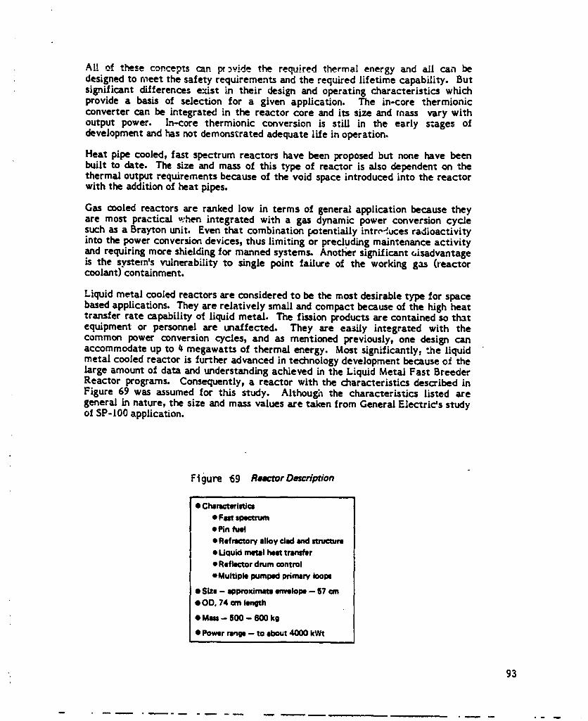
AI! of these concepts c_n p__vide the re_ired thermal energy and all can bedesigned to meet the safety requirements and the required lifetime capability. Butsignificant differences e_ist in their design and operating characteristics whichprovide a basis of selection for a given application. The in-core thermionicconverter can be integrated in the reactor core and its size and mass vary withoutput power. In-core thermionic conversion is still in the early stages ofdevelopment and has not demonstrated adequate life in operation.
Heat pipe cooled, fast spectrum reactors have been proposed but none have beenbuilt to date. The size and mass of this type of reactor is also dependent on thethermal output requirements because of the void space introduced into the reactorwith the addition of heat pipes.
Gas cooled reactors are ranked low in terms of genera/application became theyare most practical ,,.hen integrated with a gas dynamic power conversion cyclesuch as a Brayton unit. Even that combination potentially introduces radioactivityinto the power conversion devices, thus limiting or precluding maintenance activityand requiring more shielding for manned systems. Anotl_er significant _isadvantageis the system's vulnerability to single point fa/lure of the working gas (reactorcoolant) containment.
Liquid metal cooled reactors are considered to be the most desirable type for spacebased applications. They are relatively small and compact became of the high heattransfer rate capability of Liquid metal. The fission products are contained so thatequipment or personnel are unaffected. They are easily integrated with thecommon power conversion cycles, and as mentioned previously, one design canaccommodate up to _ megawatts of thermal energy. Most signLflcantly_ ".he liquidmetal cooled reactor is further advanced in technology development because of thelarge amount of data and understanding achieved in the Liquid Metal Fast BreederReactor programs. Consequently, a reactor with the characteristics described inFigure 69 was assumed for this study. Although the characteristics listed aregeneral in nature, the size and mass values are taken from Genera/Electrids studyof SP-100 application.
Ftgure 69 Re_'torDescription
v= i
• Chmct_i_cs• Fistspectrum• Pin fuel
• Refractory alloy ckKI end structure
• Liquid metal heat transfer
• Reflector drum control
• Multiple pumped primary iOOlX
• SIZe - approximate emmlope-- 57 _n
• OD, 74 on length
• Mm - 600 - 600 kg
• Power rabBI -- to about 4000 kWt
", 93
w
. m -m
1985027415-105
7.2 Power Conversion System Options
There are a number of power conversion options available for a nuclear spacepower system that can be grouped into two general classes, dynamic and static. Itwas desired to evaluate the characteristics of these two classes, and select one astypical for the later comparisons of power system location and arrangement withthe space station.
Figure 70 enumerates th_ individual power conversion cycles considered and liststhe principal attributes of each. Three dynamic cycles= Brayton, Stirlin8, andpotassium Rani_ne; and three static devices: baseline thermoelectric, advancedthermoelectric, and thermionic were investigated. Characteristics of the in-corethermionic arrangement were assumed to typify thermionic performance ingeneral.
Although the inert gas, closed cycle arrangement required for a space-basedBrayton unit is not fully developed as yet, it is similar in component design andoperation with common gas turbine machinery. Hence, it is considered to be closeto the state-of-the-art. Brayton units, like most dynamic cycles, have highconversion efficiencies although the Brayton performance is dependent onrelatively low heat rejection temperatures and corresponding large heat rejectionareas. Recuperated Brayton units are relatively bulky but can be built with largeoutputpower capacityperunit.
Stirling engines have very good performance potential in terms of efficiency andmass but need substantial development for long life, unattended space applications.They are _obably limited in unit output power capacity so a number of units wouldhave to be operated in parallel in order to achieve 100-300 kV/e total output power.
Potassium Rankine cycles have high heat rejection temperatures which, coupledwith high conversion efficiency, results in the smallest heat rejection arearequirement of all of the conversion cycles. Another of its positive attributes is alarge output power capacity per unit which would allow growth in total stationpower without the complexity of integrating many conversion units with a singlereactor. Significant advances in potassium Rankine technology developmentoccurred in the 1960's and 70's but the development was suspendedand would haveto be recovered or repeated (ref. 17).
Thermoetectrics are the most common heat-to-electric conversion devices used forspace applications, They are very reliable because of very large numbers ofindividual units which also allow a wide range of voltage-current outputcharacteristics. Baseline thermoelectric materials have been used successfully inmany diverse applications, mostly powered by radioisotope heat sources. Theirmain disadvantage is a relatively iow conver_on efficiency, although a high heatrejection temperature offsets the tow efficiency effect on heat rejection areas.
Advanced thermoelectric materials currently under development may eventuallyresult in higher conversion efficiencies than presently attainable.
Thermionic conversion is potentially more efficient than thermoelectric conversionbecause of higher hot-side operating temperatures. Although its ter.nnologydevelopment has been pursued for a number of years, more development is neededbeforea practicalunitcan be readiedfora spaceapplication.
94
1985027415-106
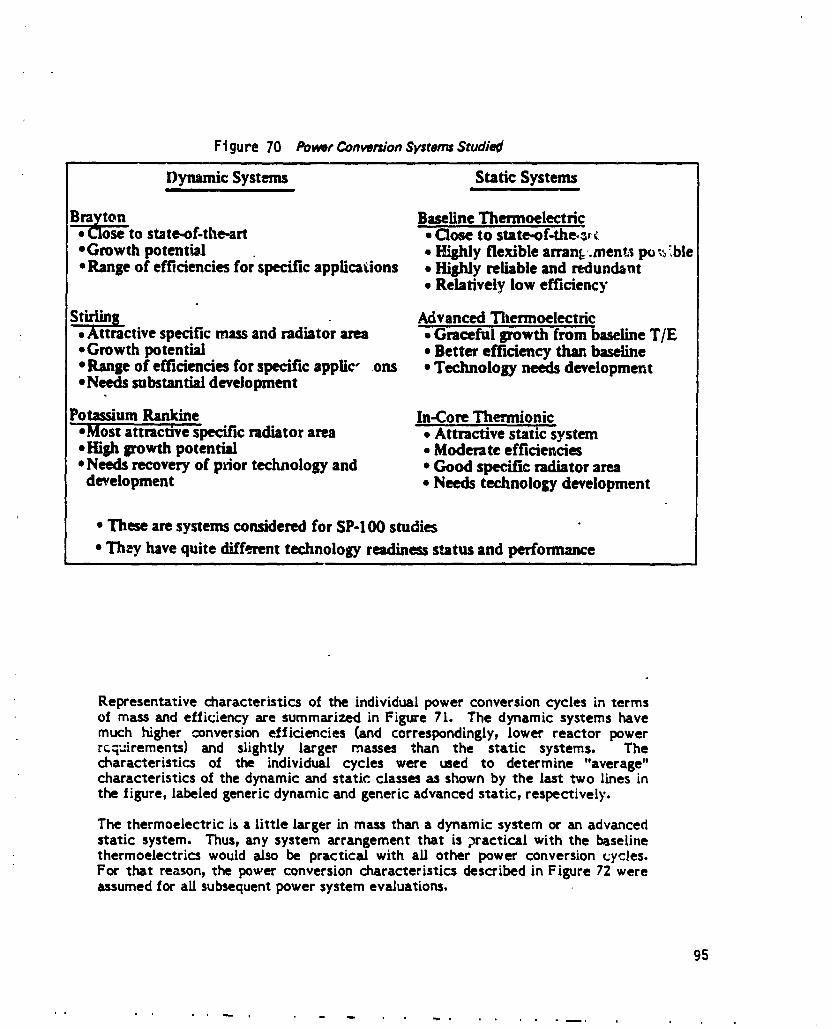
Ftgure 70 PowerConverdonSystems Studiedi . ii i | iJ
Dynamic Systems Static Systemsi I I , l
Brazton Baseline Thermoelectric• _tose to state.of-the-art • Close to state-of.the._• Growth potential • l'Eshly flexible arran_,.ment_sp_ _ _',ble• Range of eff_ciencies for specific applications • Highly reliable and redundant
• Relatively low efficiency
]_ Advanced ThermoelectricI • Attractive specific mass and radiator area -. Graceful growth from baseline T/E
• Growth potential • Better efficiency than baseline• Ranse of efficiencies for specific applic- ons • Technology needs development• Needs substantial development
Potassium Rankine In-Core Thermionic• Most attractive specific radiator area . Attractive static system• Hish 8rowth potential * Moderate efficiencies• Needs recovery of prior technology and * Good specific radiator area
development * Needs technology development
• These are systems considered for SP-I O0 studies
• They have quite different technology readiness status and performance
Representative characteristics of the individual power conversioncycles in termsof massand efficiency are summarized in Figure 7[. The dynamic systemshavemuch higher conversioneffici_ncies (and correspondingly,lower reactor powerrcq_iremenl_) and slightly larger masses than the static systems. Thecharacteristics of the individual cycles were used to determine "average"characteristics of the dynamic and static classesas shownby the last two lines inthe figure, labeledgenericdynamicand genericadvancedstatic, respectively.
The thermoelectric is a little larger in massthan a dynamic systemor an advancedstatic system. Thus,any system arrangement that is practical with the baselinethermoelectrics would also be practical with all other power conversioncycles.For that reason,the power conversioncharacteristics describedin Figure 72 wereassumedfor all subsequentpower systemevaluations.
95
1985027415-107

""--T .... - ..... -I- .....
II ' 8
_1_ R ; : _ _1 ._ .9• | _" -- ._ . w.
-,---I-- .......... 4 .....|1 I
f ._ !o o " " 2 or
---.T----------'r-----._Q
_l l
': 1If:
96
1985027415-108

Ftgure 72 SpacePowerSystern CharactertsFlcs
,, , , ,, ,,
• Uu I_seline thermoelectric sy_m
• Radiation ¢our_ladrnodu:u witP hut piPe heat transfer
• Most ¢or.tervetive ¢tmice from e sizeend rmm ,-'_ndpoint
• Assunn_ peramate.
• 5.1 percent ovmll e_,_iency
• 860K primary heat rejection temperature
• Z§ percsnt of net power rejected at 343K
• Mm _1 reactor powsr dependent on output powtr(See Table 7-2)
7.3 Shield Options
7.3.1 Materials
Lithiumhydrideisassumed to be the neutronshieldingmaterialint.hisstudy. Theselection of lithium hydride is supported by a wealth of engineering data andfabrication experience for instrument rated shields. Space nuclear reactor shieldsusing lithium hydride for the SNAP-2, _, g, and t0A were designe0 and I_uLItin thel%0's. The SNAP-IOA was successfully flown and operated in 196_. The SNAPcontractor developed the procedures and facilities for fabricating the shields up to96 inches in diameter by 80 inches thick.
Lithiur_ hydride is brittle below about 530 K, and has very little strength. It mustbe clad (usually with stainless steel) to minimize hydrogen loss at operatingtemperatures and large bodies of lithium hydride are best formed by ca:ting. It iscompacted and cast withi_ a stainless steel honeycomb (or mesh, in tight corners)to provide the strength to survive launch loads. This also assuresthat continuousaxial cracks do not develop which would result in neutron streaming and degrade(_shielding capability.
Although the need for alternate neutron shield technolo_es is not expected, bothtitanium hydride and zirconium hydride can be considered candidate materials.However, both will result in heavier neuCvonshields than !it_um hydride for thesame hydrogen density. Titanium hydride is also less stable at operatingtemperature than lithium hydride.
Tungsten appears to be superior to depleted uranium for gamma shielding in spacenuclear reactor systems. Although both have attractive high densities and meltingtemperatures and can be readily fabricated, the depleted uranium has twodisadvantages:
1. It is toxic and slightly radioactive which can compL:.cate fabrication andintroduce unnecessary nuclear s_fety complications.
97
1985027415-109

2. The residual U-23_ isotooe not removed during the enrichment process whichproduces the depleted uranium will undergo fission during space reactoroperation. This introduce_ a ,ow level fission radiation source within theshield, which increases bo¢h internal heating and shield size and weight.
Both of these problems are eliminated by the selection of Umgsten.
7.3.2 DeemRate Requirement_
The reactor shield designs are ba_l on two separate dose rate limitations to theinhabitants of the space station,
(a) A dose_Q:__f 5.72 mrem/hr at any location in the space station.
(b) A fly-by dose rate of 200 mrem/hr a,* a distance of 30 meters from thereactor.
The dose rate at the space ,ration is actually one-half the total allowable rate of35 tern/quarter, with the remaining exposure assumed to occur from naturalterrestrial and extra-terrestrial sources.
7.3.3 Shield Configuration
The basic shield geometries considered in this study are shown in Figure 67. Thede-,_nations used to describe the shield geometries indicate the solid angle ofshielued volume as measured from the reactor midplane. The four-pi configurationwould be used if the power system were within or close to inhabited _r=_s of thestation. The thickness of four-pi shields usually allows normal human _,ctivityimmediately adjacent to the shield (similar to submarine reactors).
Two-pi and conical shields protect only limited areas in a given direction from thereactor. Their principal advantage is obviously *_hemuch lighter shield masses.They would be used only at long distances from the space station and in regionsremote from approach routes to the station. The main use of these partial shieldconfigurations is for unmanned power system applications.
The shaped four-pi configuration saves shiel_ weight in those applications in whichcomplete radiation protection is required for a limited area only but some lessstringent protection is needed over all other areas, A prime example of such anapplication is a boom-mounted location of a reactc¢ power system on the spacebase. The thick, base section of the shaped four-p[ shield protects the spatestation proper while the thin side and end sections of the shield screen the EVAwork areas and shuttle approach paths to the station.
Figure 73 illustrates schematically a divided shield configuration concept designedto minimize radiation from primary loop activation or fission products. Heatexchange equipment in the gallery space between the primary and secondary shieldsections transfers thermcJ energy from the highly radioactive reactor coolant to asecondary coolant loop which then transports the energy to the power conversionequipment. Induced radioactivity in the secondary coolant loop is sufficientlyreduced below that of the primary loop to permit limited maintenance activity onthe power conversion equipment. The split shield arrangement also provides apotential method of replacing the reactor by separating it from the rest of thesystem at the heat exchanRer in the gallery location.
: 98.4
1985027415-110

I ,. ----
ORIGINAL PAGE ISOF POOR QUALITY
0
CONNECTEDTO PC$ )'
SECONDARYHEATEXCHANGEROR BOILER
RATIONALE
1 ' • MINIMIZES RADIATIONFROM RRIMARY LOOP
J J', ACTIVATION ORi FIUlON PRODUCTS
' [ • POTENTIAL FORHAND, ON MAINTENANCE
TEML-
MEACTOR _ PUMPS • POTENTIAL FOR REPLACE-MENT OR REACTOR
• IMPROVES INSTALLATION• FLEXI BILITY
POWER CONVERSION
GALLERY INTERFACE WITHWITH MULTIPLE LOOPSMULTIPLEi.oops
PRIMARYSHIELD SECONDARY
SHIELD
Figure 73 Divided Shield Concept for MannedApplications
Three shield layouts that demonstrate the use of the divided shield concept arepresented on Figures 74, 75, and 76. A design for an on-board power system,similar to a nuclear submarine installation, is shown in Figure 74. The reactor andprimary cooling loop are permanently encased within a four-pi shield structure.which is sized co permit normal activity in the immediate vicinity of the powersystem. In the strict sense,the shield ;s not divided but rather is a single unit withan internal void space used as th_ _eat exchange gallery. The reactor-shieldassembly is integral and inseparable from the space station structure.
A modification of the station integrated arrangement is the replaceable reactorconfiguration shown in Figure 75. The shield is split into two basic sections, onewhich a_ways is attached to the reactor and one which stays with the space station.The station section may be further divided into two or more parts to facilitate the.reactor removal and/or power conversion equipment reFlacement.
A split shield layout employed with a shaped four-pi shield, shown in Figure 7&, isillustrative of a boom-mounted power system in which the power conversion and/orthe reactor subsystemcould be replaced, if so designed at the outset.
99
1985027415-111

.!!
d
t ' DIAMETER " '
L_i
: t REACTOR t"-,4_$EMB[.Y "-"
!
1 --|t
PUMPSAND HEAT • Singlepock_iereactor LOOPTO PCSEXCrI_NGERS endprimaryioo] .-
• Shieldconsistsofla,,_n of LIH andTungmn
• Sizedfor 5,72 mmm/Iv ordorn_r =urf=_
• P(:3Io¢=tionI=flexible
Figure 74 Shield Layout, Four-Pi Integrated On-Board System .
tO0
1985027415-112

SECONDARYLOOPTO PCS
• Multlpkl l:)OC_lglrwctorshieldandpdmar/loop
REMOVEABLEPRIMARY LOOP SECTIONS • Rlmctortin be removedGALLERY (RE-USED) lind nlpllced
• I_rimlryloopgllllwymaybemr4tic_ble
• FixedshieldandtopIlcdonl my withItldon
• PCSmn optionlflybereplacedwithmsctor
SHIELD SECTIONWHICH REMAINSWITH REACTOR
Figure 75 Shield Layout, Four-Pi Replaceable On.Board System
TO STATION(_m)
* Separltiondlstanc_,-32m
• Conehalf4ngie-31°
• 4-wdoee rste200 mrem/hr• 30m
l • PCSInd rKIiator_
k]clltldiwly flqonlstation
• Designcanbemodemodular
REACTOR.3m ASSEMBLY
I PRIMAR:Y I
I TO PCSANDRADL6TORS
Figure 76 ShieldLayout,Four.PiShapedShield
101
1985027415-113
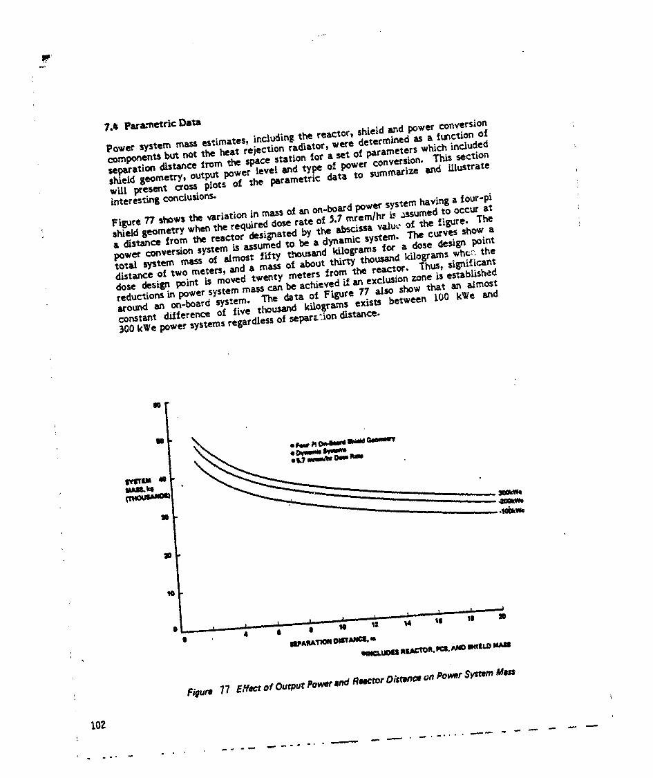
7°_ Parametric Data
Power system massestimates, incJudingthe reactor_shield and power conversioncomponentsbut not the heat rejection radiator, were determined as a f_c_on ofsepm-a¢iondistance from tJw spacestation for a set of parameters which includedshield geometry, outpu_power level and type of power conversion. This sectionwill present cross plots of the parametric data to summarize and iriustrateinteresfinz conclusions.
Figure 77 showsthe variation in massof an on-boardpower systemhavinga four-pishieldgeometry whenthe req,,ired doserate of _.7 mrem/hr L, J-_sumedto occur ata distance from 1_e reactor designatedby the abscissavaJu_"of the tigure. Thepower conversionsystem is assumedto be a dynamic system. The curves showatotaJ system ma_s of aJmos: fifty thousand kilograms for a dose design pointdistanceof two meters, and a mass of about thirty thousandkilograms who:. thedose design point is moved twenty meters from the reactor. Thus, significantreductions in power systemmasscan be achievedif an exclusionzone is establishedaround an on-board system. The data ot Figure 77 also show that an aJmostconstant dLfference of five thou_lnd kilograms exists between IC)0 kWe and300 kWe powersystemsregardlessof 5epar_'.iondistance.
a t ) _ . I _ I ........ |, , I ,L ....... - I . J I
e 4 S | m _z _4 le tl m
Figuro 77 Effectof OuwurPowerRndReectorDistwnceon PowerSysTemMen
102

,1
The variation of power system mass with type of power conversion system and atconstant output power is illustrated in Figure 78. The trends and weights of thepower system mass are similar to those shown in the previous figure. Powersystems with dynamic power conversion are the lightest while those with baselinethermoelectric conversion are the heaviest. A difference of four or five thousandkilograms exists between systems of the two power conversion types independentof separationdistance.
The data of Figure 79 are similarto that of Figure78 except they apply to ashapedfour-pishieldinsteadof an on-boardfour-pigeometry. The analysiswasextended to a much longer separationdistance because the shaped four-piconfigurationismainlyapplicableatthe longerdistances.The resultsofFigure79show that beyond twenty meters, separationdistancehas negligibleeffectonpower system masc.. The resultsalsomirror those of Figure 7g in that powersys'_emsemploying baselinethermoelectricsare about four to five thousandkilogramsheavierthandynamic power conversionsystems.
An example of the effectof shieldgeometry on power system mass ispresentedinFigure g0. In contrast to the previous figures, a very large difference in mass isapparent between the three curves of the figure. For separation distances greaterthan twenty meters, a conical shield is significantly lighter than the two-piconfiguration which, in turn, is very much lighte- than the shaped four-pi shield.The design dose rate for each of the curves of Figure 80 is 5.7 mrem/hr at thespace station. However, the shaped four-pi geometry has side and end shieldingthat allows flyby operations within thirty meters of the reactor while the completelack of side shielding in the other two geometries precludes suchflyby approaches.Thus, practical limitations on the use of the conical and two-pi geometries offsettheir respective mass advantages.
7._ SpecLfic Electrical Power Systems
Based on the results of the parametric shield mass calculations and subsequentspacraft tradeoff studies, three configurations of electric power system-spacestation integration were identified for continued evaluation,"
(a) A boom-mounted power system located 70 meters from the station
(b) Power systems tethered to but operating at a distance of about 30 kilometersfrom the station
(c) A free-flying powe: system operating in an orbit 700 kilometers higher thanthe space station
1 For each of these configurations, a baseline power requirement of 1_0 kWe net to: the s*_ationwas established, assumed to be provided by the baseline thermoelectric
power conversion cycle. A duplicate set of evaluations was performed for each ofthe power system-space station configurations assuming a net power requirementof 300 kWe supplied by an advanced dynamic conversion cycle. Discussions for _Jlof the configurations are contained irJthe succeeding paragraphs.
I
103
1985027415-115
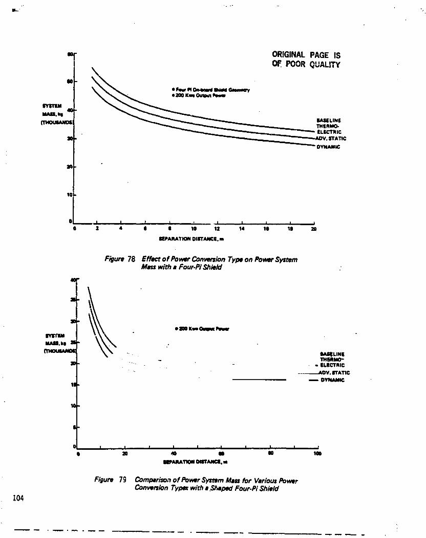
r'
_0
tl J , I I I ' _ I | , I I ,., I0 2 4 O | 10 12 14 10 10
IIIPAII_TION OllrrANCi. m
Figure 78 Effect of PowerConversionTypeon PowerSystemMasswit_ a Four.PiShield
4=
li
IO
o lOOKweOIlm _
W_ll, kl 11
(13404JWkNO_ _ &IkSI_LIN|- THMMO-
10 -- - - ., ILICTIlilC-- ---.--_,A_OV. ITATIC
-_ D_ICI|
W
|
0 I ,, I I I , I I I . I I II l= _ tO I0 lm
1191_RATIONOBTIU_¢I. m
Figure 79 Comparisonof PowerSystemMassfor VariousPowerConversionTypeswith •,_pad Four-PiShield
104
1985027415-116

"T31
Ii CONICAL
ql I I I I I I I I I I0 20 40 I0 I10 100 120 140 100 180 200
SEPARATIONOIIrI'ANCE,m
Figure 80 Effect of Shield Geometry on Po_r System Mass
7.5.1 Boom-Mounted Configuration
A layout of the 150 kWe boom-mounted reactor power system is presented in: Figure 8l. In this configuration, the electrical power is delivered to the space
station via aluminum cables. The 70 meter boom length was established bydetermining a minimum overall weight of reactor power system plus cabling as afunction of boom length. With shorter booms, the increase in shield weight wouldbe greater than the weight savings in the conducting cable, with reverse conditionsoccurring with booms longer than 70 meters.
As shown in Figure $l, a shield half angle of 22.#o protects the space station at the70 meter separation distance. The shield thickness within this angle is sized toachieve the 5.7 mrem/hr design dose rate in the station. The shaped four-pi shieldgeometry is slightly thinner on the sides and on the end away from the station tomeet the flyby doserate of 200 mrem/hr. The primary and secondary loop bays arelocated on the far side of the shield from the station in separate shield sections_,hich, in theory, can be disconnected to provide for replacement of either thereactor assembly or the power conversion unit. The latter component, though notshown in Figure gl, is physically attached to the shield section concaining thesecondary loop bay.
The shield mass for the layout shown on Figure gl is estimated to be lg,000kilograms with the mass of the reactor plus power conversion an additional 1,650kilograms. A summary of the boom-mounted system characteristics, as well as thecharacteristics of the other configurations, are listed in Figure g2.
105
1985027415-117
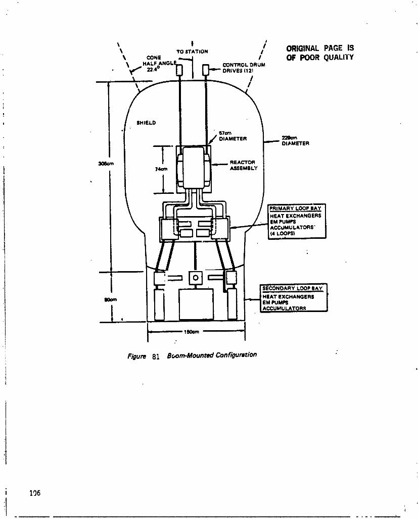
t ! ORIGINAL PAGE iSTO _rATION /CONE I OF POOR QUALITY
_,, HALF CONTROLDRUM• v ,_ omves(12_
I
i
SHIEL0
STemDIAMETER 229am
DIJkMETER
-1-306¢m REACTOR74¢m ASSEMBLY
• _k
;: /" Lo?,,=
"1 ISECONDARY LOOPBAY...t,,.,d HEAT EXCHANGERS
ll0=m IEM PUMF$./ACCUMUU_,'roR.q,,
J IB0cm =
Figure 81 B(,om.MountedConfiguration
; 106
iI ,,.... f
1985027415-118

J ORIGINAL PAGE IS
Figure 82 ChamcteristiclofSelectedPowerSysternConfigurarions OF 7.3OR_ QUALITY_{ m,zliz= =m_m
.! n_= =o._==umo=m_= =uJli=tz0) =,mrr,_zxRAtzoj FMo_¢v=lismmli[THO0 OFPOWEII
_] TllAliSmlSIOli METALCOIIOUCTORS |LECT_OL_ PLA_T EL|CTIIOLYS_PLA_ [LECTII0LYImSFlJUET: 8ASELINET/E
: t R_ lrTR[ BASELIIIlETR IIA_UII_ T_ BASEUII| T/_
i [LECTIIICPUllfEIIIIEO.', NETTOSTAT10R IM Mge lU Mh IM kWe tU kWe
•! NETPCS0UTII_ 113kWe ZOOWe 201_ _ kWe
RPAIIAI10N oarrAlu 70• m am" 5 • _ i_0 STATm| 01iPAYLOA0
Slqll[LOTY'M SHAPEOfOUli4'l FOIIR,iq CONICAL COIIICAL(MANRATED) (MA_ UT|0P (INSTRUMENTIIATE0| (INNSTIIUMENTRATEDI
90n RATESUE0' ATSTATION0R PAYLOA0 1.7mm_br L3_ 14Am_kf 14_ nm_kq
fl¥4¥ NO mm_kr • N • 281_ • ]0 • UNSnDFIE0 UNSPECIFIED
MASS(II|ACTOII &Iq_ IlM he 2110he 21N he _ he
VOLUME(IIlACTOII& II_CS) Z.I n | 2.1 n I 1,8 oi I Z.JIaml
M _HIELO) 1Nm kl 11700k_ 190ks _ kl
,, VOLUMEMHI|LD) 7.1• | 7A • ] U m| IJ • ]
SYSTEMORAl;AIIEA "1.1 an| "_1 n 2 I.II an| U ann2
eMAII-RATEDFOIlMANII[O MAIIITENARCIEAF'IIR REACTORSHUTDOWIIAIIO FLY4Y
7..%2 Tethered Co¢ff];_ration
The layouts of two distinctly different tethered configurations are shown inFigures 83 and S#; a man-rated system in the former figure and an instrument-rated system in the latter. In both systems, the electrical power generated is usedin an electrolysis plant to decompose water J,lto its hydrogen and oxygencomponents. The gases are then pumped through hoseswhich are grouped togetherto form the umbilical tether between the reactor power system and the station. A¢the station, the hydrogen and oxygen are recombined in the fuel cell to generateelectrica_ power when needed, with the reformed water returned to the powersystem electrolyzer through tether ducts to complete the cycle. The power system
, is held by the tether under tension approximately 30 kilometers distance away from
_1 the space station in a higher _ltitude.;I
The man-rated tethered configuration shown in Figure 83 has a four-pi shieldgeometry that Ls sized to allow flyby approaches during Power system operation,and manned maintenance in the power conversion unit and electrolysis plant afterreactor shutdown. The primary and secondary loop design in corresponding shieldsections is identical in function to the boom-mounted design of Figure 8]. Thetethered systems must generate higher gross power outputs than the boom-mountedsystem because of the power required to run the electrolysis plant. This highergross power is reflected in the slightly heavier masses for the shield and power_onversion componentsas shown in Figure 82.
107
1985027415-119

p,
CONTROl. DRUMDRIVES (12)
SHIELD
57¢m
DIAMETER
I-301cm 74¢m REACTOR
A_;EMIILY
i " I
PRIMARY LOOP BAYHEAT EXC_
• EM PUMPS/ ACCUMULATORS
14l.o!oPs)
SECONDARY LOOP SAY
S0cm m---,-- HEAT EXCHANGERSEM PUMPS
ACCUMULATORS
|EOom , L I
Figure 83 TetheredConfiguration(MRnRmmd)
108
1985027415-120
The instrument-rated tethered configuration has a shield mass that is only Iiveperce,_t of the mass of the man-rated configuration (see Figure 82). This is due toits conical shield geometry with a cone half ang'e of only 17o, as shown inFigure 84, and a much higher allowable dose rate. This type o! shadow shieldprecludes manned approach to the power system so the dose rate is determined bytolerances of instrumentation located approximately twenty-five meters awayfrom the shield. Thus, a very substantial savings in power system mass is realizedfor the disadvantage of excluding manned maintenance of the power converter andelectrolysis plant.
7.).3 Free=FlyerCmffiguration
The iree-flyer configuration is similar in shape and concept to the instrument-rated tethered system in that a conical shadow shield geometry is used to protectan unmanned power conversion system and electrolysis plant. A much largerelectrolysis plant, hence more electrical power, is required in the free-flyingconfiguration to provide propulsive fuel for a tanker which transports licluifiedoxygen and hydrogen fuels from the power system to the space station. Therequired electrical power of 360 kWe exceeds the capacity of a power system usinga single _ megawatt thermal reactor with thermoelectric conversion.Consequently, two of these _ MWt reactors, placed end-tc_-end in tandemarrangement, were assumed as the nuclear energy source for the system, eventhough a redesigned, single reactor of greater thermal energy output might resultin a smaller mass for the overall system. The conical shield tor the free-flyingconfiguration is considerably larger than the conical shield of the tetheredconfiguration because of the two reactor arrangement, the higher total reactorpower level and the larger area payload (power conversion subsystem pluselectrolysis/liquefaction plant) to be protected.
7._.4 300 kWe Dynamic Systems
The configuration evaluations described in the three preceding report sections forI50 kWe net power output to the space station were repeated for assumed netpower output requirements of 300 kWe. To produce this quantity of power it wasconsidered necessary to assume the use of more efficient advanced dynamic power
J conversion as represented by Stirling engine systems. Layouts for the boom-mounted, tethered, and free-flying configurations were not prepared because theywould be very similar to those shown in Figures gl, g3, and g#. The maindifferences would be the substitution of four Stirling engine components for theheat exchangers in the secondary loop bays of Figures 81 and 83, and slightlysmaller shields due to higher conversion efficiencies.
A summary of the $t_rling engine system characteristics is presented in Figure 85.Comparison of these characteristics with those of Figure 82 show slightly lightershield masses for the $tirling engine configurations even though the n_=tpower tothe station is doubled.
7.6 System Design and Operational Considerations
Some design and operational aspects of the reactor power system were examined ina preliminary manner for th_s study. The areas considered include startup andshutdown operations, maintenance and repair possibilities, safety aspects of thedesign and operation, and reliability/lifetime concerns. The following paragraphsdiscussthese various considerations.
109
1985027415-121

!i 110
1985027415-122

#
1985027415-123
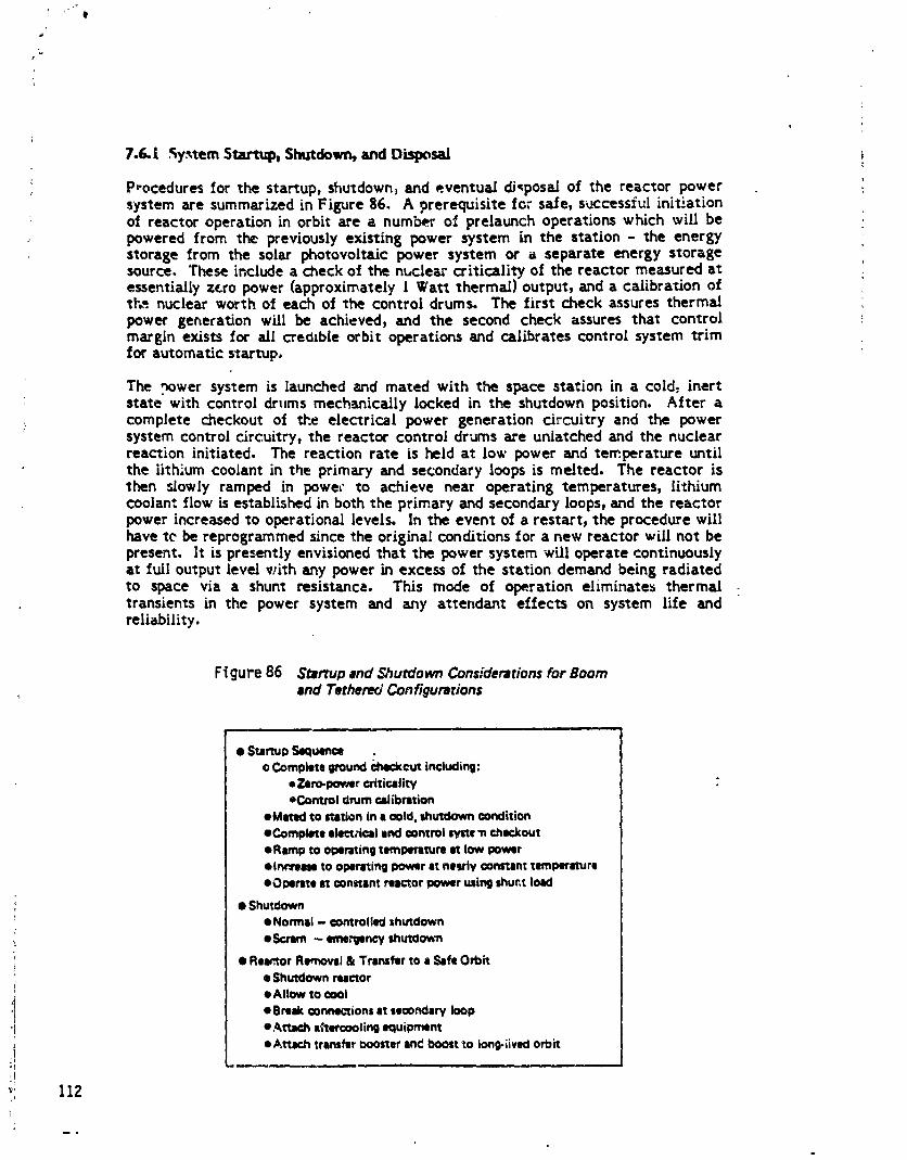
I '" e
7.6. L Sy._temSUu'tu_ Shutdown, and Disposal I
P,ocedures for the star, up, shutdown, and eventual dJ,posaJof the reactor power :system are summarized in Figure g6. A prerequisite for s_fe, successful initiationof reactor operation in orbit are a number of prelaunch operations which will bepowered from the previouslyexistingpower system in the station- the energystoragefrom the solarphotovoltaicpower system or _ separateenergy storagesource.These includea checkof the nuclearcriticalityof the reactormeasured atessentiallyz_ropower (approximately[ Wat_ thermal)output,and a calibrationoft_-.nuclearworth of each of the controldrums. The firstcheck assuresthermalpower generationwillbe achieved,and the second check assuresthat controlmargin existsfor aH crecllbleorbitoperationsand calibratescontrolsystem trimforautomaticstartup.
The nower system islaunchedand mated with the space stationin a cold_inertstatewith controldrums mechanicallylockedin the shutdown position.After acomplete checkout of tJ'.eelectricalpower generationcircuitryand the powersystem controlcircuitry,the reactorcontroldrums are unlatchedand the nuclearreactioninitiated.The reactionrate isheldat low power and temperatureuntilthe |ith:'umcoolantinthe primaryand secondaryloopsismelted. The reactoristhen _lowlyramped in powec to achieve near operatingtemperatures,lithiumcoolantflowisestablishedinboththe primaryand secondaryloops,and the reactorPower increasedto operationallevels.Inthe eventofa restart,the procedurewillhave tcbe reprograrnmedsincethe origina!conditionsfora new reactorwillnot bepresent.Itispresentlyenvisionedthatthe power system willoperatecontinuouslyat fulloutputlevelwithany power inexcessof the stationdemand beingradiatedto space via a shunt resistance.This mode of operationeliminate_thermaltransientsin the power system and any attendanteffectson system lifeandreliability.
Ftgure 86 $_rtup and Shutdown Considerations for Boomand Tethered Configurations
• S_rtuaSaquer_ .oCompletegroundcheckoutincluding:
• ZerO-lX_aercriticalityeControldrumcaJibnltion
eMetedto orationina mid,shutdownconditioneCompleteelectricalendoontrolsyst¢_ncheckoutoRarnptooperatingtornperttumstlowpowereinr_mmtooperatingpoweratnelrlv constanttemperatureeOl_reteit constantreactorpowerusingIhur,t load
• ShutdowneNormld- controlledihutdown• Scrim- Im_noy mu_o_n
• Re.or Removel & Transfer to a Safe Orbit• Shutdown reactor
• Allow to _ol
oBmak connections lit leoondary loop
"I e,_tti_ i_tercoolin9 equipment• AtlK.h transfer Ooosterand boost to Iong-livKI orbit
:1"II
_: 112
i
1985027415-124
B
Two shutdown procedures are shown on Figure g6: a normal, controlled shutdown,and an emergency "scram" shutdown. Tt_e latter procedure would be available forman-rated configurations to deal with potentially catastrophic accidents. The"scram" procedure might be an irreversible action that would preclude subsequentrestart of _ power system.
Disposal of t_e reactor at :he end of its useful life would be accomplished by thesequence listed in Figure ga. The reactor would be shut down and allowed to coolboth thermally and radioactively. If the power conversion subsystem were to bereused, it would be separated from the reactor at the secondary loop bay andreplaced with a temporary aftercoo_ing subsystem, if a_tercooling is still needed.A booster vehicle would be attached to the primary shield section containing thereactor and the reactor disconnected from the station. The reactor section wouldthen be boosted to a safe orbit and abandoned.
7.6.2 Ma_tenance and Repair C_mideratiens
Instrument-rated shield geometry systems employing shadow type shields o! limitedsolid angle must be designed for long life without planned maintenance or repairbecause their nuclear environment precludes manned activity in the immediatevicinity of the system. However, man-rated systems with some form of four-pishielding geometry offers the potential for limited maintenance and repairactivities. The specific shield arrangements shown in Sections 7.5.1 and 7.5.2contain extra gamma shielding which would allow limited contact maintenance orrepair operations on the secondary heat transfer loop components and powerconversion modules after a system shutdown. Twelve days after a reactorshutdown, the dose rate at the secondary loop bay would be approximately100 mrem/hr, which would allow a person to work at that location for 2 to 3 hoursper day. Approximately seventy-three days after system shutdown, the dose ratewould decrease to 30 mrem/hr at that location which would permit an g-hourworking period per day. The use of heavier gamma shield sections would allow themaintenance/repair activities to commence sooner or extend for longer workperiods per day. Considerably more detailed evaluations are needed to determinethe usefulnessof Jirnited maintenance and repair and the extent of those activities.Of prime importance is the effect that maintainability would have on the overallreliability of the power system. This evaluation would have to be made inconjunction with parallel studies to identify practical maintenance activities andcomponent candidates for periodic repair or replacement.
7.6.3 Safety
The safety aspects of any nuclear reactor powered system are always of prime
ii concern, and the space application of that type of system creates a number ofpotentially hazardous conditions not present in ground based applications. A
, number of those conditions and potential solutions have been identified but• : considerably more analysis and development will be required. Some of the areas of: ; concern that have been identified are:
i l) Nuclear subcriticality during postulated accidents.2) Reactor core dispersion upon re-entry into the earth's atmosphere.3) Containment of liquid metals during system operations._) Safe control during operations,5) Achievement of safe disposal of the reactor.6) )Provisionfor safe haven power tf reactor power system fails.
i 113
ii ...... .
1985027415-125
r
Achieving and/or maintainingnuc_-.arsubcriticalityfollowing accidentsduringprelaunch,launch,and operationalphases of the missionis an essentialsafetyconsideration.The controldrums of the reactorwillbe mechanicallylockedintheshutdown positionforalloperationsleadingto reactorstartupinorbit.Additional
i controlsystem interlockswill be designedintothe system forsafetypurposes.Inthe event of a launchabortthatresultsin the water immersion of the reactor,a
i separate removable safety plug of nuclear "poison" material may be bui.lt into theit reactor to offset the positive nuclear effect of the water on the reactor criticality.1 Also, a "scram" capability may be designed into the control drum actuators, or into
separatescran_controlrods,to quicklyshutdown an operatingreactorlocatedothe space station in the event of a_ accident. For any safety operations, the Dowe_
_1 .viH be provided from an emergency power sy_em.(
A safety condition that must be addressed is the accidental re-entry of a nuclearly1 'Rot" reactor into the atmosphere. P-!sent ruling requires that the reactor be
passively disassembled into small discrete sections that burn up in the atmospherebefore impact on the surface of the earth. With a four-pi shield geometryenveloping the reactor, removal of the shield must be achieved before the reactorcan be dispersed. Analyses will have to be performed to determine if the shieldremoval will occur r_turally in its passage through the atmosphere or if separationcapability must be designed into the component. A design can be made in whichthe shie!d will separate from the reactor.
j Before operation of the power system, the lithium coolant is cold and solid. Afteroperation has been achieved, the molten lithium must be contained in the event ofa break in the coolant circuits, because of its very corrosive capability and itsradioactivity in the reactor loop. In man-rated four-pi shield geometries, theenvelopin8 configuration of the shield could provide a secondary containmentstructure for the primary cooling loop, if so designed. However, the secondary
' coolant loop penetra+_.s the shield volume, thus a fracture of this loop wouldj release liquid metal to the surroundings. Design studies are required to determine
_) the necessity, and methods, of liquid metal containment from normally exposed1 coolantcircuits.
_() Sa_e operation of the reactor power system will require a fall-resistant control
3 system. This will probably be accomplished by fully redundant electric andelectronic control circuitry, a built-in capability for manual override of the
:! controls, and an independent, uninterruptible power _upply for _I componen*s qfthe control system. Such an independent power supply can be an advanced high
! energy density lithium battery.i
J 7.&4 ReUabili_and Lifetime Considerationsi
The first space reactor power system development is expected to be the SP-100application which ._._san eventual reliability requirement of 93% for seven years offull power operation. It will have a design life requirement of ten years and a full
,! power lifetime requirement of seven years. It is assumed that the SP-100 will-_ meet its life and reliability goals and that a man-rated reactor power system forI the space station application will be based on the SP-100 design. At the presentI time there is no reason to expect significantly shorter life or lower reliability for
the manned space station version of the system. However, there are somei differences in the design and application of the space station version that will have! to be evaluated. They include:
114
1985027415-126

" I) The reliabilityof additionalsafetyfeatures_ncludcdin the m__n-ratedpowersystem andtheireffecton overallsystemreliability
2) The effecton overallsystem reliabilityof provisionsmade in the designtoprovidemaintainability)ifpresent
3) A free=flyingconfigurationfor the reactorpower system which would havean instrument-ratedconicalshieldgeometry, but wi1_ provisionfor so,neflybyactivityby manned vehicles.
The system mass of man-rated reactorpower systems isdominatedby the shieldcomponent)and thebulkof thatshieldmass isneededto provideflybycapabilityinany directionfrom the reactor. The shieldmass for a man-rated system isapproximatelytwenty metrictonnes,which providespossiblecapabilityforlimitedcontactmaintenanceon particularcomponents ofthepower system.
The shieldmass of the free-flyingpower systemconfigurationisonly".hreemetrictonnes)a very significantreductioncompared to the man=rated systems of theothertwo configurations.Thisrelativelysmallmass accruesfrom the use of aninstrument-rated,conicalshieldgeometry inthefree-flyingarrangement.
iI.i,s
:i
,i-I_,, 115,I:t
1985027415-127

LO SPAC'_ STATION TRADE ST-u_OIES
Of fourteen space station-reactor configuration options assessed_ three wereselected on first order merit for further quantitative evaluation. These threeinclude one reactor which is rigidly attached to the space station, one which isattached to a long tether, and one which is a free-flyer. Conceptual designs weredeveloped for each configuration to identify the major elements and to enable aquantitative estimate of ma_s, volume, and orbital drag area. A comparison ofconfil_urations on the basis of mass and volume in orbit, and STS logistics wasmade. The comparison included initial operations and life cycle logistics. Powerlevels considered were 150 kWe and .300 kWe net power to the space station.
8.1 System Selection Recapitulation
8.1.1 Confisuratiom
Three configuration options were selected for further analysis. These optionswere: 1) reactor attached to a boom on the space station with electrical powertransmitted through conducting cables to the station; 2) reactor and electrolyzerattached to a long tether_ with oxygen and hydrogen flowing through the tether toa fuel cell on the space station and water returning to the reactor; and 3) reactorand electrolyzer on a free-flyer in a higher orbit than the space station, withreactants transferred to and from the space station with ar orbital transfervehicle. The major elements of each option are illustrated in Figure 87 through 89.
The boom-mounted reactor configuration is shown in Figure 87. The reactor ismounted at the end o_ a boom which is attached to the space station. The powerconversion system_ shield, and radiators are at the reactor end of the boom. Powertransmission from the power conversion system to the space station is achievedwith conducting cable_ within the boom. An OMV or OTV Lsprovided at the spacestation which is available at any time for boosting the reactor to a high orbit. Anemergency power system is also available at the space station to provide criticalpower to the station during power failures.
, Figure 88 shows a tethered reactor system in which the reactor is at one end of along, flexible tether and the space station is at the opposite end. The powerconversion system, shield) and radiators are at the reactor end of the tether.Power transmission to the space station is achieved by moving gaseous hydrogenand oxygen) produced by the electrolyzer) to tanks at the reactor. From the tankstorage, the gases are pumped through hoses in the tether to holding tanks at thestation. Electrical power is produced at the space station with fuel ceils. Thewater produced by the rule cell is then returned to the electro|yzer through hosesin the tether. At the space station a small vehicle is provided for boosting thereactor to a high, long-Jived orbit.
, The free-flyer reactor system is shown in Figure 89. The reactor, powerconversion system, shield, and radiators are on a free-flying spacecraft in a long-lived orbit, while the space station is at a lower orbit. Water is electrolyzed andthe hydrogen and oxygen are liquefied at the reactor to minimize transportionvolumes. Electricity is produced at the space station with fuel cells. An orbitaltransfer vehicle is maintained in a hangar at the space station. When the free-flyer and station orbits are in phase, the OTV leaves the space station with a fullcharge of water plus sufficient H2-O2 propellant for a round trip, carries the waterto the reactor, and returns to the station _ith a full charge of separated fuel cell
116
1985027415-128
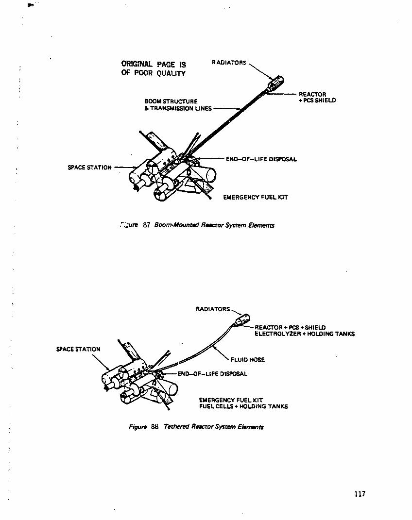
Im
r
ORIGINALPAGE IS RADIATORS; OF POOR QUALITYt
REACTORBOOM STRUCTURE + PCSSHIELD& TRANSMISSION LINES
END-OF-LIFE DISPOSAL
SPACE STATION
EMERGENCY FUEL KIT
F.:ure 87 Boom-Mounted Reactor System Elements
RA_)IATORS ._
_ REACTOR �IzCS+ SHIELD
_ ELECTROLYZER + HOLDING TANKS
_"FLUIO HOSESPACE _TATI_
END--OF-LIFE DISPOSAL
EMERGENCY FUEL KITFUEL CELLS + HOLDING TANKS
Figure 88 Tethered ReK'mr System ElemenB
117
1985027415-129

RADIATORS
_ REACTOR+ PCS+ SHIELD
ELECTROLYZER+ LIOUIFIER +
ST _
• OTV
FUEL TANKS
EMERGENCYFUEL KITFUEL CELLS + TANKSOTV HANGAR
Figure B9 Free Flyer Reac¢or System Elements
118

r
reactants. The reactants are stored as liquid o_,gen and liquid hydrogen, so thatthe free-flyer also has a liquefier, a low temperature radiator, and storage tank_.Fuel cells, an emergency power system, and an OTV hangar are stored at the spacestation. An analysis was made to determine the logistics and the approximatenumber of shuttle launches required to support this part of the mission.
g.1.2 Net Power to Station
The three configurations were analyzed with the same net electrical power at thespace staticm. Since power losses are different in the three cases, then theelectrical output of the reactor is different in each case. For the boom-mountedoption, a transmission line wa_ selected with resistive losses of 2% of the netelectrical power. Other losses are assumednegligible, so the net electrical outputof the reactor is I53 kWe for the boom-mounted case. In the tethered reactor
; case, an electrolyzer efficiency of 90% and a fuel cell conversion efficiency of80% results in a required reactor electrical power of 208 kWe. (See sections g.3and 8.# below). The required reactor electrical output for the free-flyer is
: 360 kWe, as described in Section $.8.#. The reactor output for 150 kWe net to thestation is summarized in Figure 90. Trade studies were also performed for a netpower of )0G kWe at the station, with reactor powers doubled over the 150 kWecase.
FIGURE 90: NET REACTOR ELECTRICAL POWER
Confi/_uration Reactor OutputBoom-mounted 15) kWeTether 208 kWeFree Flyer 360 kWe
8.1.3 Power Conversion System
As described in Section 7.2, several power conversion system options werei investigated to determine the interrelationships with the Space Station. For the
trade studies at 150 kWe, a baseline thermoelectric system was selected forcomparison. This was considered to be the most conservative choice from a sizeand mass viewpoint. The overall power conversion efficiency using radiation-coupled modules with heat pipe heat transfer was assumed to be 5.I%. Waste heatis rejected at two different temperatures: 97.5% of the hea¢ is rejected at 850 K,
; while the remaining 2.5% _ rejected at 3#3 K.
A more advanced system was considered for a later space station option. Thissystem used a Stirling cycle heat engine with a net electric power to the spacestation of 300 kWe. This system was investigated to provide a comparison withhigher power and with advanced dynamic conversion systems. The power conver-sion efficiency was assumed to be 25%, with 96.7% of the waste heat rejected at atemperature of 6#0 K and 3.3% rejected at 3#3 K.
119
1985027415-131

+
&l.# Reactor System
The reactorsystem selectedfor the tradestudiesisthatdescribedinSection7.1.Itisbasicallya fastreactorwith pin-typefuelelements,refractoryalloycladdingand structures,and drum-type reflectorsfor reactivitycontrol. Heat removalfrom the reactorcore isby multiplepumped liquidmetal loops. This designisevolvingfrom theSP-100 projectwitha designthermalpower of 4000 kWt. Due t_burnup limitationswith this design,the reactor system assessed for thethermoelectricfree-flyerwas actuallytwo reactorsintandem. Thisapproachwastakento allowa burnupinexcessof 40 MW-years fortheexistingdesign.
ILI._Shield
The shield design was described in Section 7.3. For the boom mounted reactorcase,a shaped .*our-pishielddesignwas used,with an allowablecontinuousdoserate at the space stationof 12._ rein per quarterfrom the reactoralone of_.7mrem/hr, and a maximum dose rateof 200 mrem/hr at a distanceof 30 metersin any directionfrom the reactor.The former doseraterepresentstheallowablecontinuousdose to peopleresidingon the space stationforhalfa year,whilethelatterdose rate representsoccasionaldoses of shortduration(I-2hours)duringorbiteror EVA maneuvering. The shielddesignconsistedof lithiumhydrideforneutronshielding,encapsulatedinmultiplelayersof tungstenforgamma shielding.
For the tetheredreactoroption,two shieldtypeswere considered.A man-ratedshieldwas consideredto allow manned trafficin the vicinityof the reactor.Thiswas a fourpishieldwitha doserateof200 mrem/hr at 30 meters from the reactorduringoperation.Thisshieldmight alsoallowlimitedmanned maintenanceafterreactorshutdown. A conlcalshieldwas alsoconsideredwhich isnot man-rated.:The dose rate for thisInstrument-ratedshieldis 14.4rem/hr at a distanceof 25meters from the reactor,behindthe shield.A conicalinstrument-ratedshieldwasalsoassessedforthe free-flyercase.
8.2 Radiator Parametrics
The reactor radiator sizes were determined parametrically for all the powerconversion systems. One-sided cyiindricaJ radiators and two sided flat plate• ,
radiators were considered. The results are summarized in Figures 91 and 92. Theradiators summarized in these tables are assumed to be "white", meaning the solarspectrum absorptivity is 0.2, and the emissivity is 0.9. This sizing was done for:areference 100 kWe, based on optimizatJon of a simple model to achieve minimummass. Meteoroid protection is not included in the model, since it is beyond thescope of the contract. The scaling with power levels greater than 100 kWe isassumed to be linear with electrical power. Cylindrical one-sided radiators weretreated in the trade studies.
8.3 Fuel CeU Scaling Parameters
STS fuel cell data were used as the basis for fuel cell scaling parameters.Hydrogen and oxygen are electrochemicallyconverted to water to produceelectricalpower. The maximum continuouspower outputof these unitsin theorbiteris7 kW at a flowrateof 2.6kg/hr,with an efficiencyof 6.[%. The O2/H 2ratio is g:l. These units weigh 91 kg with a volume of 0.134 mJ. With periodicservicing, these units may accumulate 5,000 hours of on-line service.
120
1985027415-132

, Figure 91 Cylindrical One-,_ided Radiator Size for I00 kWe
PrimaryRadiator SeconderyRadiatori tt ml
System Thermal Rejection Ar_ Mass Thermal Rej,_'tion Area MassType Power Temperature Power Temperature
(kW) (K) (m2) (k0) (kW) (K) (m2) (kg)
Brayton 345 550 116.0 415 10 343 28.1 65
Stirling 290 640 52.0 213 10 343 28.1 65Baseline 1858 850 104.0 549 3 343 8.4 20Thermoelectric
Advlmcad 1009 850 56.4 298 3 343 8.4 20Thermoelectric
Thermionic 880 850 49.1 260 20 343 56.0 129
Potanium 390 750 29.5 146 10 650 1.7 6_
Renkine I
Figure 92 Two-Sided t:lat Plate Radiator Size for 100 kWe
PrimaryRadiator Se_ndaw Radiatort i Hit it i
System Thermal Rejection Area I_s Thermal Rejection Am MassType Power Temperature Power Temperature
(kV,_ (K) (m2) (k9) (kW) (K) (m2) (kg)
_i Brayton 345 550 57.9 255 10 343 15.3 44
Stirline 290 640 25.8 130 10 343 15,3 44
Bmline 1858 850 51.3 330 3 343 4.6 13Thermoelectric
• Advance_l 1009 850 27.9 180 3 343 4.6 13f Thermoelectric
r
't Thermionic 880 850 24.2 156 20 343 30.7 88! Pota,ium 390 790 14.5 88 10 650 C.8 4.1
Rankine
L
"1
: 121
1985027415-133

This study assumesfuel cell efficiency will reach g0% by the mid-90's and that thatreliabilityand lifetimecan _e increasedto meet the 10-yearprogram requirement.A factorof 1.5was appliedto theST$ fuelcellmass and volume data to accountfor spares,and for electrical,fluid,and structuralsupportequipment. The fuelcellscalingparametersusedare listedinFigure93.
g._ Electrolyzer Scaling Parameters
The scalingparametersused for the electrolysissystems were obtainedfrom asurvey of regenerativefuel celldata (Ref. 17). The study used solidpolymerelectrolyteunitsfor space-basedwater reductiono! propellants.Some of theadvantagescitedinclude:I)minimum power requiredperunitof gas generatedand2) 10-20year lifepotential.Althoughthe flowratesinthe referencedstudyweresignificantlyhigher(7700 Ib/hrvs. g0-2#0 lb/hr)the scalingparameters wereassumed to be approximatelylinearwith fiowrate.The post-processingreactantgas de-humidifierwas discussedseparately.Because of itssmallrelativesizeinthisstudy,the de-humidifierparametershave been includedin the electrolyzerscalingparameters. These parametersalsoincludewater coolingof the electro-[yzers,and the water circulationsystem. Figure94 liststl_sstudy'selectrolysisscalingparameters.
IL._ Emergency Fuel Kit
Since the emergency power system can have itsown power or itcouldderiveitspower from the prime power supply,an emergency power system was devisedforthe case where a separatepov.ersupplydidnot exist.The same basicemergency__uelkit was used for all three configurations.Fuel was storedat ambienttemperature(300K)in glass-wrappedtanks. Ten kWe averagepower was assumedforemergency operationsfor 2! days (5040 kWhe). Water is vented overboard.Stationradiatorswere used. The fuelcellswere &_sumed tobe g0% efficient.This
subsystemweighs5.gt and hasa volume of 23 m 3.
ILl;Boom-motmted ReactorConfiguration
The boom-mounted reactorproduces3000 kW of thermalpower with a conversionefficiencyof 5.1%, resultingin I_3 kW of electricalpower and 2947 kW of wasteheat. The optimum boom lengthisdeterminedby addingthe reactorshieldmass tothe mass of the transmissionwiresand boom structure.The shieldisa man-rated
shield,taken hereto be a shapedfourpiconfiguration.The shieldmass was shownin Figure7-II as a functionof distancefrom the station.The wire mass can be
calculatedas M - 2n Prl_ [_, where
n isthenumber of wirepairs(n= 2 takenhere),I:)- mas_ densityof theconductor(I:)= 2700 kg/m3 foraluminum),
= electricalresistivity(rl= 2.94x t0-8_-m forAI at 50oc),p = electrical power (P = 1_0 kW taken here),V = voltage (V = 150 V taken here),
AV = voltage drop through the line ( AV = 3 V taken here),JListheboom length.
For two pairs of aluminum wires carrying t_0 kWe at 150 Volts with a 3 Voltpotential difference, the wire mass is M = 0.122 JL2, with 1_% of the wire massadded for insulation. The boom mass is taken to be 1.5 kg/m, or 1 ibm/ft. Thecombined reactor, PCS, shield, wire, and boom mass is shown in Figure 95 as a
122
1985027415-134
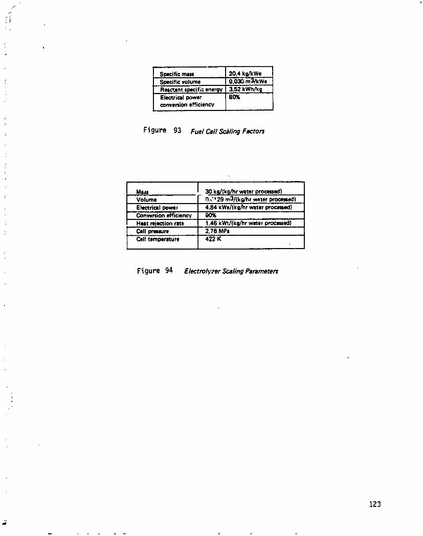
Specific mm 20.4 ko/kWe
Specific volume 0.030 m3/kWe
Ructent specific enemy 3.52 kWh/k 9" Electrical power 80%
conversionefficiency
Figure 93 Fuel Cell ScalingFactors
Ma= _ 30 kg/(kg/hr water processed): Volume 0.C' 29 m3/(kg/hr water procesl_l)
Electrical power 4.84 kWe/(kg/hr water processed)
Conversionefficiency 90%Heat rejection rate 1.46 kWt/(kg/hr water p_K:l)
: Cell pressure 2.76 MPa
Cell temperature 422 K
Figure 94 ElectrolyTer ScalingParameters
123
1985027415-135
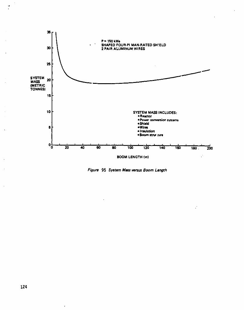
=lP- 1R0kWe
• SHAPEDFOUR-PIMAN.RATED SHIELD30 2 PAIR ALUMINUM WIRES
25
SYSTEMMASS 20(METRICTONNES)
15
10 SYSTEMMASS INCLUDES:• Rlactor• PowerconversionsystemsoShieid
6 eWirls• Insulation• Boomstnx _ure
O0 | I I i I i i i I i i I I i I I I i i I20 40 60 80 100 120 140 160 180. 200
BOOMLENGTH (m)
Figure 95 SystemMassversusBoom Length
124
1985027415-136

functionof boom lengthfor a 153 kWe re=_ctor,!nsr_ctionol thisfigureshows abroadminimum inthe system mass between about 50 and 80 meters. Thisoccurswhen the shieldmass asymptotic=flyapproachesi_snlinimum because the fly-bydose dominates,resultingin more of a uhiform four-pishieldthan one which isweightedtoward the spacestation,whilethe wire mas.=,isincreasir_by the squareof the boom length.The absoluteminimum occursat about 70 me'_ersseparationdistance.
The boom-mounted reactor configuration system masse._are shown in Figure 96.The mass of..the 153 kWe reactor with power ;onversio,nsystem is 1650 kg, and thevolume is .?.Ira3. A shaped four-pi shield a 70 meters scl:eration distance weighslg,000 ktl and occupies 7.ira 3 volume. The primary radiator, which rejects 2g_3kWt at 8_0 K, weighs S_0 kg, The secondary radiator, which rejects _ kWt at 3_3K, weighs 31 kg. A cylindrical, one-sided radiator was assumed in this study. Theradiator volume is 16#m). The total drag area for the reactor/shield/radiatorconfiguration, is 5#m2, of which #8.2m 2 is due to the primary radiatt, r.
The transmissionlinesare compcsed of two pairsof aluminum wires with adiameterof 3.0cm and lengthof 7_ meters. The mass is687 kg with insulatmn.The volume is0.2m3 and thedragareaisg.#m2. The boom mass ist05kg.
3#o additional subsystems are requi_'ed at the space station for a boom-mountedr=.actor power supply. The first is a propulsion stage to bcost the reactor andshield to a long=lived orbit at the end of its useful lifetime or following a seriousaccident. An orbital maneuvering vehicle (OMV) is capable o_ performing thismission and will be available when the space station is operational, so it was usedin this study as a reference booster. In actual practice, a smaller booster withlesser capabilities would also be adequate for the end of life disposal mission, butOMV specifications are in existence and it seems reasonable that availableequipment would be used. A dedicated OMV is not necessary, but operationsrequirements may dictate that one be present in a state of operational readiness incase of a serious reactnr accident. The space station also has an emergency powersystem, to be used during any reactor shutdown as described in Section 8._. Thiskit is a fuel cell set which provides 10 kWe for 2[ days. The fuel cells' mass is 203kg, the fuel supply mass is t#20 k_., and the tank m_tssis #i70 kg. The volume ofthe fuel tanks is 22.6m 3, and that of the fuel ceUs is Jo3m3.
The totalsystem mass is31,$30;<gforinitialoperati._uand occupiesa volume _I236m3° The launchvehicleto the spacestationwillt. thespace shuttle.Launchcapabilityof the STS to a 500 km circularorbitwith an inclinationof 2g.5° iscurrently19.5tonnes,(ST5UsersHandbook). With an augmented thrustersystem,thisisexpectedto reach 25.0tonneswithina few years.The availablevolume inthe car_obay is300m3.
An 5TS manifestplanisshown in[-igure97. The reactor,power conversionsystem,shield,radiator,boc.m,and transmissionlinescan be launchedto _he space stationin a singleshuttleflight.The payloadmass would be 21.2tonnes,and the volumewould be 193m 3, resultingin a load factorof 0.85. The orbitalmaneuveringvehicleand emergency power kit would be launchedon another flight,with apayloadmass of 10.3tonnesand a vulume of #3m 3, resultingina load factorof0.t_l. The total number of shuttle flights to place the operational system at thespace station is therefore 1.26.
125
1985027415-137

RADIATORS0.87 t
,l§3kWe REACTOR+ PCS+END-OF-LIFE SHIELD 19.65tDISPOSAL4,5 t 70 METER BOOMSTRUCTURE
0.1 t
2 PAIR ALUMINUM TRANSMIt;SIONLINES3 cm DIA_,'_TER0.6 t WITH INSULATION
EMERGENCYFUEL KIL (21 DAYS x 10kW)REACTANTS 1.4 tTAN KS 4.2 tFUEL CELLS 0.2 t
Figure 96 Mau Statement for 150 kWe Boorn-Moun_d Reactor Configuraffon
°*
126
I
1985027415-138

• i ii " i i
FLIGHT CONTENTS MASS VOLUMENUMBER (t) (m3)
• _ amlm_m I n,
R'F.ACTOB,PCS,SHIELD, RADIATOR 20JS 173I
BOOM + TRANSMISSION LINES 0.7 20i,
OMV 4,5 20I_ '-
"EMERGENCY POWERKIT 5.8 23iii i i1,,
RECURRING DRAG MAKEUP PROPELLANT 0.47 1.1
(I_Y_R LIFE (INCLUDING STATION)CYCLE)
's_"_ sEc I ToAUG.EmED_ KMORB,TSTSL,_,,TS ZS_CURRENT LIMITS 19.5
Figure 97 STS Mtqifest Plan for Boom-Mounted Reacmr Sysmm (150 kWe)
127
1985027415-139
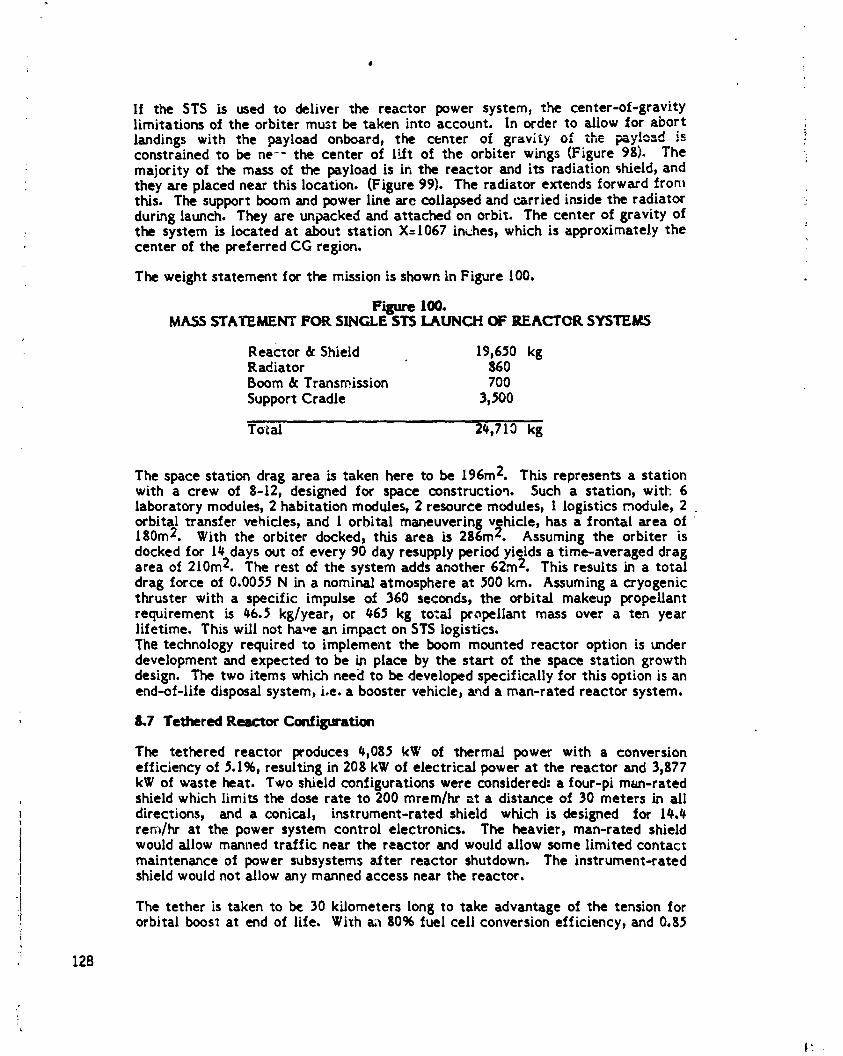
If the STS is used to deliver the reactor power system, the center-of-gravitylimitations of the orbiter must be taken into account. In order to allow for abortlandingswith the payload onboard, the center of gravityof the F_ylo_d isconstrainedto be ne-- the centerof IRt of the orbiterwings (Figure9g). Themajorityof the mass of the payloadisinthe reactorand itsradiationshield,andtheyareplacednearthislocation.(Figure99). The radiatorextendsforwardfromthis. The support boom and power line are collapsed and carried inside the radiatorduring launch. They are unpacked and attached on orbit. The center of gravity of
; the system is located at about station X:I067 in_es, which is approximately the 'center of the preferred CG region.
The weight statement for the mission is showninFigure lO0.
10o.MASS STATEMENT FOR SINGLE STS lAUNCH OF REACTOR SYSTEMS
Reactor & Shield 19,650 kgRadiator 860Boom & Transmission 700Support Cradle 3)_00
Tot_ 2_,710 kg
The space station drag area is taken here to be 196m2. This represents a stationwith a crew of 8-12, designed for space construction. Such a station, with 6laboratory modules, 2 habitation modules, 2 resource modules, I logistics module, 2orbital transfer vehicles, and I orbital maneuvering vj_hicle, has a frontal area of180m2. With the orbiter docked, this area is 286mz, Assuming the orbiter isdocked for I# days out of every 90 day resupply period yields a time-averaged dragarea of 210m2. The rest of the system adds another 62m 2. This results in a totaldrag force of 0.0055 N in a nominal atmosphere at 500 kin. Assuming a cryogenicthruster with a specific impulse of 360 seconds, the orbital makeup propellantrequirement is 46.5 kg/year) or #65 kg tot=! propellant mass over a ten yearlifetime. This will not have an impact on STS logistics.The technology required to implement the boom mounted reactor option is underdevelopment and expected to be in place by the start of the space station growthdesign. The two items which nee¢l to be developed specifically for this option is anend-of-life disposal system, Joe.a booster vehicle, and a man-rated reactor system.
8.7 Tethered Reactor Confil_ation
The tethered reactor produces #,0g5 kW of thermal power with a conversionefficiency of 5.1%, resulting in 20g kW of electrical power at the reactor and 3,877kW of waste heat. Two shield configurations were considered= a four-pi m_m-rated
. shield which limits the dose rate to 200 mrem/hr _t a distance of 30 meters in alldirections, and a conical, instrument-rated shield which is designed for l#._
i rem/hr at the power system control electronics. The heavier, man-rated shieldwould allow manned traffic near the reactor and would allow some limited contactmaintenance of power subsystems a_ter reactor shutdown. The instrument-rated
{ shield would not allow any manned accessnear the reactor.I
i] The tether is taken to be 30 kilometers long to take advantage of the tension for1 orbital boost at end of life. Wi_h a;_ 80% fuel ceil conversion efficiency, and 0.85
[
l: 'l
1985027415-140

I
I=! I e ,5o I40- iI
WEIGHT i SHUTTLEPAYLOAD__ _.. - IHT& CG(KLBS) 30 - ! LIMITVSCG _/ WEIGI
20- ; _ I
10 I
I Xo/13020 II I I I I I I 1
000 700 800 9rjO 1000 1100 1200 1300
SHUTTLECOORDINATE(Xo)
Figure 98 Single Launch Weight Distribution (!50 kWe)
REACT_.COLLAPSED il \ \"K/_
SUPPORTRADIATOR CRADLE
F/gum 99 Single Launch C_rgoBey Manifest
129
1985027415-141

l
lbs of H 2 & 0 2 per KWH, the space station needs a fuel flow rate of 42.6 kg/hr.The water volumetric flow rate from the _tation to the reactor is therefore 0.0426m3/hr, or 1.18 x 10⁻⁵ m3/s. The volumetric flow rates of hydroRen and oxygenfrom the reactor to the space station are 0.169 m3/s and 0.008# m37s, respectively:at a static press'jre of 100 kPa (1 atm) and a tempereture of 313 K. Three waterlines, three oxygen lines, and three hydrogen lines are bundled together for systemredundancy and fail safe operation. The hoses are made with 5-mil thick mylarwalls and the bundle is wrapped with 15 layers of multi-layer insulation to preventwater freezing.
The water hoses have a diameter of 1.06 cm. This Allows laminar flow with a
, velocity of 4.5 cm/s and a frictional pressure drop of 250 kPa. The pressure safetymargin is about 15. The gas hoseshave a diameter of 6.0 cm. The hydrogen flowveloc;.ty is 2.0 m/s with a pressure drop of 2.8 kPa, and the oxygen flow velocity is1.0 m/s with a pressure drop of 12.5 kPa. The pressure safety margin is aboutthree.
The tethered reactor configuration system masses are shown in Figure t0t. Themass of the 208 kWe reactor with power conversion system is 2100 kg and thevolume is 2.1 m 3. The man-rated shield mass is 18,700 kg and the volume is 7.#m3, whL[ethe instrument-rated shield is 890 kg _.nd0.5 m3, The primary radiator,which rejects 3871 I-V/t at 850 K, weighs It#0 kg. The secondary radiator rejects 5kV/t and weighs 31 kg. The radiator volume is 2#5 m3, The electrolyzer mass is1600 kg, with a 25% excess capacity, and occupies 0.7 m3.
Fuel generated at the reactor is pumped into holding tanks. Fuel is drawn fromthese tanks into the tether hoses, and flows to tanks on the space station. At each
: enci of the tether are holding tanks containing oxygen and hydrogen gases andwater. A twelve-hour fuel supply at full power, or 1800 kwh reserve, is stored at
1 each end. The full tanks weigh 2100 kg, including structure and pumps, and occupy
i 38 m3.
j The space station has an emergency power system (safe haven power) for use whenthe reactor is not operating or if the fuel is not flowing. This consists of sufficient
.j fuel and storage tanks for lO kWe operation for 21 days. Together, the emergencyt fuel kit weighs 5800 kg and occupies 23 m3. The main fuel cells which supply 150! kWe to the space station, weigh 3700 kg, with a twenty percent excess capacity.! An orbital boost vehicle can be stored at the space station for reactor boost to a! long lived orbit, ifrequired.
The tether itself consists of nine mylar hoses (3 each of the H2, 02, and H20 forreliability) wrapped in a bundle of multi-layer insulation. The empty tether weighs15,000 kg. The hoses must be filled before operation commences. The mass ofwater in the hosesis 79#0 kg.
The total system mass is 64,700 kg fo¢ initial operation and occupies a volume of369 m 3 in its stored configuration. Ar. 5T5 manifest plan is shown in Figure 102.The reactor, power conversion system, shield, radiator, and electrolyzer can belaunched to the space station on a single shuttle flight, with a load factor of 0.95.A second flight wouid carry the tether in a collapsed configuration, the fuel cells,and both sets of holding tanks, for a load factor of 0.92. A third flight would takethe emergency power kit, water, and an orbital transfer vehicle, for a load factorof 0.73. The total number of 5TS flights to place the complete system in its initialoperation condition is less than three: a full cargo bay equivalent of 2.60. The
130
1985027415-142
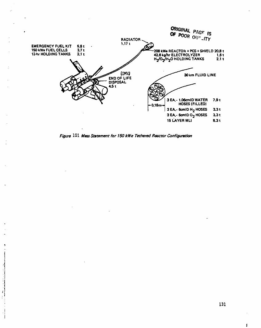
• ORIGINALPAGr ISRADIATOR OF POOR OU_ ITy
EMERGENCYFUEL KIT 5 8 t 1.17 t150kWeFUEL CELLS 3_7t /_208 kWeREACTOI_+ PCS+ SHIELD 20.8 t12-hrHOLDING TANKS 2.1t_2.1t 42.6 kg/hrELECTROLYZER 1.6 t
/_,'__ ENDtOF LIFE LUID LINE
L_, DISPOSAL
_4,5 ] _ ] 3 EA,- 1.06cmlDWATER 7.9 tFO.lSm. _ HOSES(FILLED)I ...... 13EA.-_,o.2HOSES3.3,
3E_-_,o 02HOSES3.3,15_VE,M., 8.3,
Figure 101 Mass Statement for 150 kWe Tethered Reactor Configuration
fli 131t
,, _
1
1985027415-143
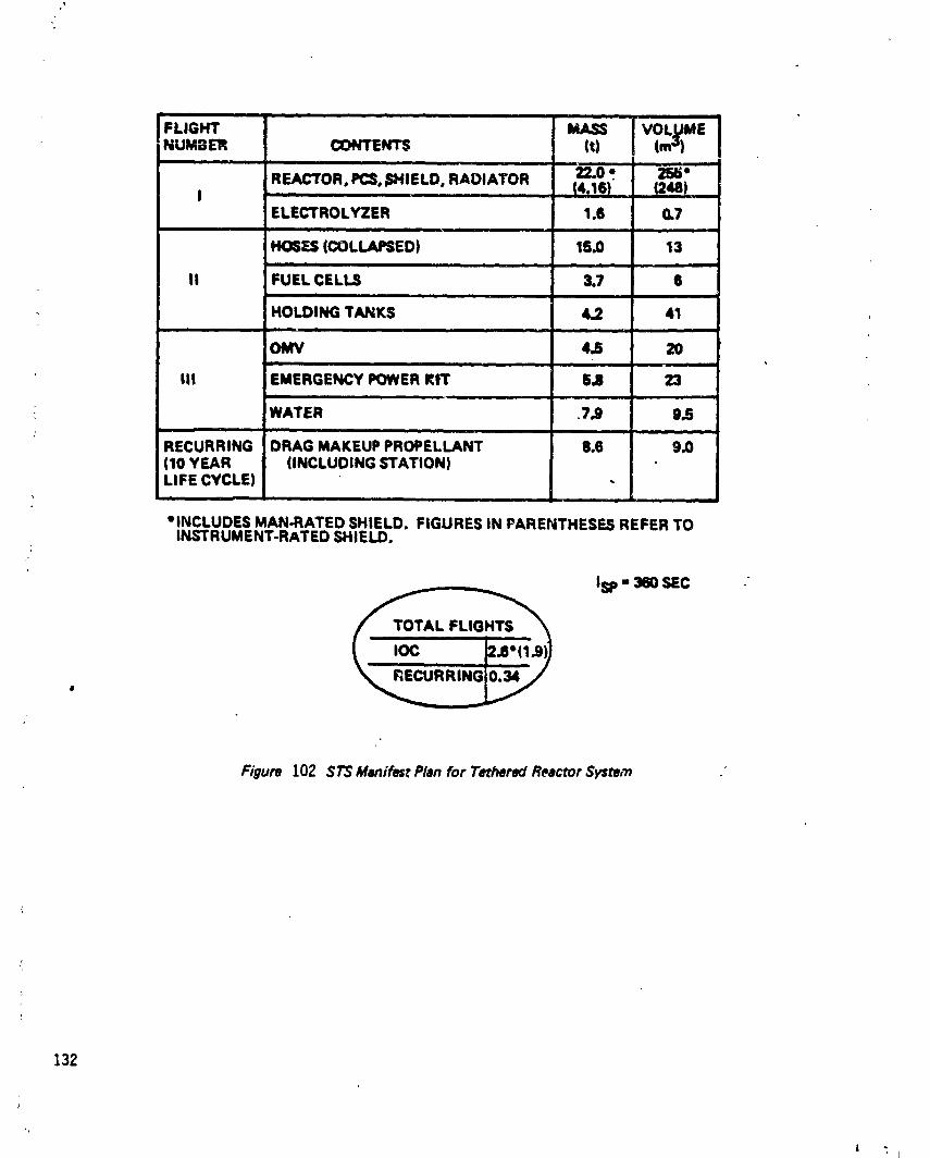
I I | ii
FLIGHT MASS VOLUMENUMBER CONTENTS (t) (ms)
ii ii • ,
REACTOR. PCS._SHIELD,RADIATOR 22.0 ¶ 255"(4,16) (2U)
i im • |
ELECTROLYZER 1.8 0,7i | i |
HOSTS (COLLAPSED) 15.0 13i liB I i
II FUEL CELLS 3.7 6i |. i
HOLDING TANKS 4.2 41| I ii
4.5 20i i •
III EMERGENCY POWERKIT 5.8 23i | • |1
WATER 7,9 9,5
RECURRING DRAG MAKEUP PROPELLANT 8.6 9.0(10 YEAR (INCLUDING STATION)LIFE CYCLE)
r m •, i i
elNCLUOES MAN-RATED SHIELD. FIGURES IN PARENTHESES REFER TOINSTRUMENT-RATED SHIELD.
Isp - 360 SEC
Figure 102 $TS Manifest Plan for Tethered Reactor Sysm,'n
132
' i
1985027415-144

R
numbers in parentheses in Figure 102 are for an instrument-rated shield• The fullorbiter equivalent is 1.9 if equipment can be manifested inside the radiator
, envelope.
As shown in Section 8.6, the time-averaged space station drag area is 210 m2. Thefrontal area of the tether is 5400 m2, while the atmospheric density decreases byone-third. The drag force on the system is 0.09(; N. The orbital makeup propellantrequired is g55 kg/year, for a ten yea:- cumulative total of g550 kg, oc 0.34equivalent orbiter payloads. Ninety-four percent of this drag is due to the frontalarea of the tethered hosebundle itself.
Most of the technology required to implement the tethered reactor option iscurrently under development. The fuel system is essentially a regenerative fuelcell with the electrolyzer and fuel cell separated. The space-based electrolysisprocessneeds to be developed for this program if it is not already developed by thestart of space station operation. Tether dynamics needs to _e understood.Micrometeoroid protection may be necessary for the hosesand some form of leakdetection and repair technology would need to be incorporated. As with the boom-mounted reactor option, an end-of-llfe disposal system is required.
$.8 Free-Fly_ ReactorConfiguration
8.8.1Introductic_
The basic free-flyingreactor configurationwas discussedabove in g.l.i. Arequirementof a 300 year safe orbitfor thisconfigurationwas imposed. Thisconstraintimplieda min;mum 800-700km orbitforthefree-flyer.Becauseof thelongperiodbetween co-planarfree-flyer/stationorbits,themain system driverwasthe amount of reactant requiredin orbit to fulfillthe totalpower x timerequirement.Thisrequirementfurtherimpacted the fJelphase and the transfervehicleselected.
Figure 103 describes the basic free-flyer sc_:nario. The reactor andelectrolysis/liquefaction plant process water and store the reactants until the
I reactor and station are co-planar. A Space Based OTV (5BOTV) flies from thestation to the free-flyer with a fully loaded water tank and empty LH2 and LO2tanks, drops these tanks off, and Tetrieves the empty water tank and full LH 2 and
j LO 2 tanks for return to the station. During the resupply mission - which would
take less than I day - the -,ration operates in a minimum power mode ( 10 kW)using the emergency backup kit for fuel. Makeup fuel to replace SBOTVpropellant, boiloff, and other losses are brought to the station from earth in the
• form of water, and then flown to the free-flyer for processingon its next resupplymission.
:'I 8.8.2 Orbital ConsiderationsFor purposesof this study, the space station was assumed to be in a circular orbitat 500 km altitude and 28.5° inclination. Resupply orbit transfer requirements andstrategies with the reactor in a circular orbit at altitudes of 800, 700, 900, and1200 km and 28.5o inclination were analyzed.
Gravitational pertubations due to the earth's oblateness cause changes in orbitelements over time. In this study _he change of greatest interest was the drift in
Z33
iI
1985027415-145

FREE-FLYER DRYERRADIATOR RADIATOR HIGH
TEMPERATUREPADIATOR
LO2 I-H2 ELECTRULYZERRADIATOR RADIATOR RADIATOR
02 H2 UOUIFIER ELECTROLYZER ELECTRIC REACTORUOUIFIER ANDDRYER CONVERSION
LO2 LH2 WATER IRCULATIONTANK TANK TANK
AVIONICS& CONTROL
DOCKINGAND EMPTYTRANSFER REACTANT EMPTY
TANKSONTO WATERTANK RE ,0 TANKTOTO 01"V TO REACTOI REACTOR
FREEFLIER
EMPTYWATERTANKSONTO TANKONTO TANKSONTO H.20TANK
STATION STATION 0TV ONTOOTV
PACESTATION
WATERTANK
i'H2' L022 FUELCELLS TOIWATIONTANKS POWER
SUS r- -- - --STS
CARNY
EMERGENCY WATERUPFUEL RADIATOR ON5"1"$KIT
Figure 103 Free-Flying Reactor Scenario Block Diagram
134
A , *
1985027415-146
It
the longitude of the ascending node (_) due to first order secular perturbations.Thi_ rate of drift is:
J2,_=-{ (l_e_) , (Ra--_' cos i
where _l = rate of change of longitude of ascending node,J2 = zonal harmonic coefficient ( = 1.0$263 x l0 -3 ),
= orbital mean motion,e = orbit eccentricity,Re= Earth radius,a = orbit semi-major axis,t = orbit inclination.
Since both orbits are circular and at the same inclination, the difference in driftrates is a function of altitude difference. The differential ascending node driftmeans that most of the time an orbit transfer between the space station andreactor would involve a plane change, which is expensive in terms of a V, andtherefore propellant consumption. Figures 10_ and 105 show the resulting aVrequirements. In Figure I0_ the requh'emen_s are shown as a function of thedifference in ascending nodes. It,, Figure 105, the drift rates have been taken intoaccount to show the AV requirements as a function of time since the orbits werecoplanar rather than of the difference in longitude of the ascending nodes. It canbe seen in both figures that the AV requirements become prohibitive when theaJcending nodes are more than about 25° apart. From Figure 105, it can be seenthat the orbits are close to coplanar every 180 days w,_enthe reactor is at 1200 kmaltitude, but this occurs only every I090 days when the reactor is at 600 kmaltitude. This suggeststha_ the launch windows for fuel transfer occur on13 onceevery 0.5-3 years. This and t),_ power demand determine the tanks payload size.
One way to reduce the long time between launch windows is to use phasing orbits.: By using a_. :.ntermediate) transfer orbit with a different ascending node drift rate,
the tr;_nsfer can be achieved in tess time than it would take for the station andreactcr orbits to become copianar and for Jess&V *ban a direct transfer. Tot=--_.f :r from the spac:estation to the reactor, three burns are needed. In the first,
: the transfer o_qt =?_gee is raised to the selected altitude (higher than the reactoraltitude). The perigee is then raised to the reactor altitude. After the phasing(transfer) orbit ascending node and reactor orbit node coincide, the final burn ismade to circularize at the reactor altitude. The tra=_sit times for the four reactoraltitudes and a variety of phasing orbit apogees are shown in Figures 106a throughd along with the time required for the station _nd reactor orbit ascending nodes tocoincide. The corresponding aVs are shown in Figure 107.
• It can be seen from Figures 106 that the transit time using phasing orbit,._ areusually less than the time needed for the station a_d reactor orbits to becomecoplanar. The z_V requirements are less than for most direct transfers betweennon-coplanar orbits since all of the phasingorbit burns are in-plane.
In most casesshown_the difference in the semi-major axes o._the phasing orbit andthe reactor orbit is greater than the difference between the semi-major _xes of thespace station and reactor orbits and the ascending node relative drif£ ra_e iscorrespondingly greater. In addition, since the phasing orbitts semi-major axis isgreater than the reactor orbi£s, the relative drift rate is in the opposite directionfrom that of the reactor and station orbits.
135
#
1985027415-147

400o _ I ' I
t ' 'lI
¢ 'X.uw(_r Eler!7 D Je 1,o T_o
)im,_nsl)na De_enerac_2soo • .
iREACTORALTITUDE,KM
600, O1000 700. I!} --
1200. 0
500 :
o I0 I00 200 300
(deQrea)
Figure 104 Orbit TransferDelta V Requirements asa Function of OrbitPlane Difference and Reactor Altitude
136
JL *i
1985027415-148
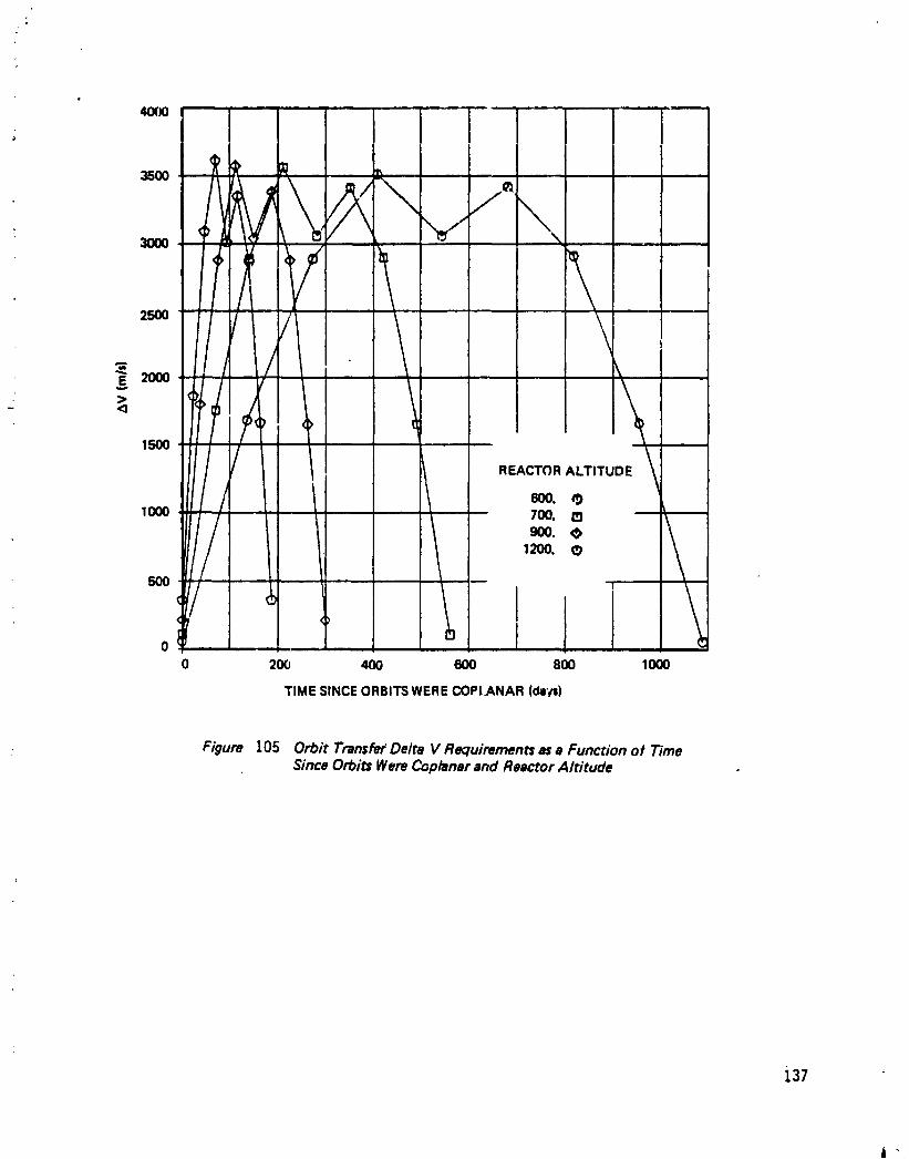
40(X) i ' ' "I
=oo ?1 \1!9 i_ .¢
000 ,_ it. i i |
I " i
: :: V
2500 : , ;.. 0 , •I
I
.=_ =t I . J [,.
2000 : i II
> _ \l
1500 : :" • 1 \\
/II REACTORALTITUDE
11 °°1000 700. O)9O0. _ \
1200.
I ill j ',i
o ' I I _0 2OO 4OO 6OO 80O 1000
TIME SINCEORBITSWERECOPLANAR(da'_)
• Figure 105 Orbit Transfer Delta V Requirements as a Function of TimeSince Orbits Were Coplanar and Reactor Altitude
J,37 '_
1985027415-149

1000
t_
900 - "_ , ,
800 PHASING ORBIT APOGEE
• 700 ' 150o •2OOO •3OOO &
• 600
500 ....
,® - __._ ----__0
0 2OO 4OO 6OO 8OO 1000
TIME SINCE ORBITS WERE COPLANAR (days)
Figure I06a Orbit Transfer Transfer Times With PhasingOrbit-.Final OrbitAltitude 600 l¢ilorneters
.
138
t
1985027415-150
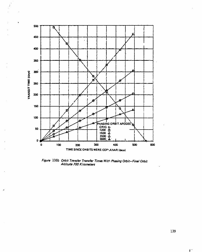
,!4+o P" ,. I _
\ ,/_,, /
+o \ J:,_30o" ,._ :/ - _'
u.+-. _<' //_- 25o \
< 20O _"-/¢ ,.. / '_ /
mo / ." \
'+ .-++ .... ,+'+o_°+-,\0 30O0, A' .I -I
0 10O 2OO 3OO 40O 5OO
TIME SINCEOHBITSWERECOP'.ANAR (days)
Figure 106b Orbit Transfer Transfer Times With Phasing Orbit-Final OrbitAltitude 700 Ki iometen
139
1985027415-151

?
450 ,_ n " '
ORBITALTITUDE 500 KILOMETERS / !NITIAL
I
_o j,PHi _SlNGORBIT APCGEE
ORIG C_ /35O 1500 ,','1 /2000_
25O _ ---
. -,,,./ _z
0 100 200 300
TIME SINCE ORBITSWERECOPLANAR(DAYS)
Figure 106c Orbit Transfer Transfer Times With Phasing Orbit-Final OrbitAltitude 900 K._iometers
140
i
1985027415-152
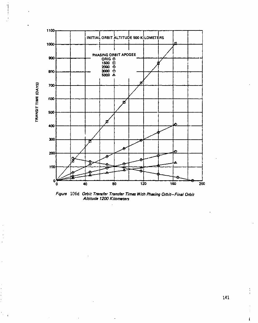
I
INITIA 1 ORBIT ALTITUDE 500 KILOMETERS
i l / °1000. I
PHASINGORBIT APOGEE //
900 ORIG O / '1500 D
=° //8nO _ O5000_
_ 700 ....
w
= f,oo. /t,nZ 500,
= /F-
I 7 '
_ r. "-'_"
00 40 80 120 160 200
Figure I06d Orbit 7"rar_fer Transfer Times With Phasing Orbit-Fina/ OrbitAltitude 1200 Kilometers
14.1
i
1985027415-153
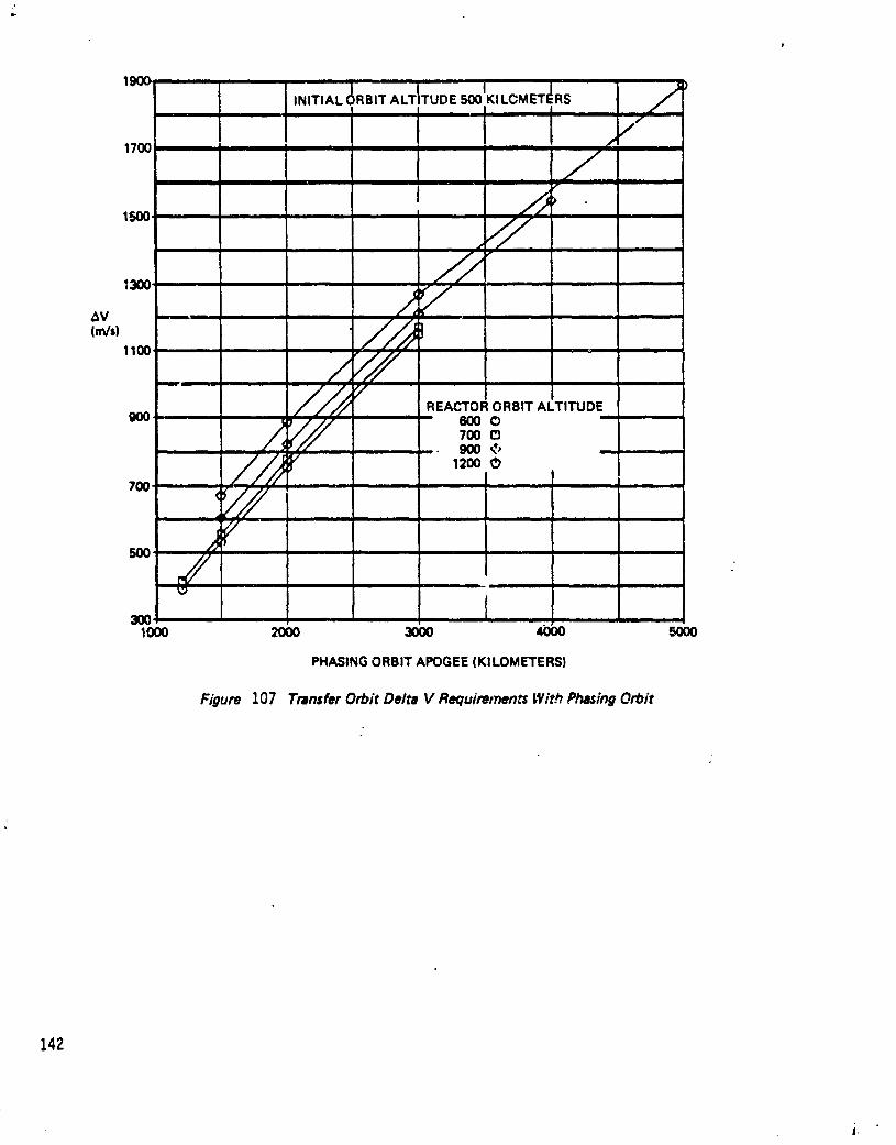
,ooK,LoM_+d.s/,N,+,.L&.,T._TI+UDE'iil I i I ill
17oo , /,t
1500 .....//
I [ g in J I _ _ g i
J/*'_ 22" '
,+., //_IlCX_" ,
zYf
_/" REACTORORBIT ALTITUDE
900 , 6000 ' "
700 C9900 .&,
//_ ,_o700 ..... "'"
'/Ji|
500 ,
PHASINGORBIT APOGEE(KILOMETERS)
Figure 107 Tmn=fer Orbit Delta V Requiremen_ Wit.h Phasing Orbit
142
J,
1985027415-154

A_ an example of a resupply strategy using phasing orbits, the case where the spacestation was in a 500 km altitude orbit, the reactor was in a 700 km orbit, and thephasing orbit apogee was 1300 krn (Figure t06b) was studied. A tanker launched
_, when the two orbits were coplanar would arrive the same day. The next tar, kercould be launched after 30 days, with a transit t:me of 19 days, thus arriving _9
, daysafterthe lastone. Thiscouldbe continuedevery 30 days for 360 days,untilth=.transittime via the phasingorbitbecame greaterthan the time tmtilthestationand reactorv erecoplanaragain. Meanwhile,the tankersweuld be arrivingatthe reactorevery_9 days.
Inallcasesusingphasingorbits,theAV requirementislargerthan theAV requiredfora directHohrnanntransferorbitbetween the space stationand reactor.Thus,the increasedlaunchfrequencycan be achievedat the expenseof increasedOTV
, propellantrequirements,increasedreactorpower,and increasedOTV fleetsize.
Although the minimum AVs for coplanarorbittransfersare relativelysmall,thelongpe_riodsbetween them implyvery largereactantpayloadsfor the highstationelectricpower requirement.Reducingthe periodbetween transfersincreasestheminimum AV. A compromise between these conflictingfactorswas made inselectinga 1200 km circularorbit.Inthisconfiguration,a transferisperformedevery i80 days with AV = 325 m/s. Over the 10 year system life,20 flightsarenecessary.Even forthe 150kWe stationrequirement,each fuelpayloadis230 t.
$.8.3FuelPhase5election
Three differentoptionswere consideredforreactantstorageand transfer=I)gas,2)supercritical,and 3)liquid.Figure10g liststhe advantagesand disadvantagesofeach. Tank mass and volume were evaluatedforeach optionassuminga I00 kWestationrequirementwith 30 day resupplyat 65% totalsystem efficiency(72,000kwh). FigureI09presentsthetankmass and volume ratiosrelativeto liquidtanks.These ratiosincreasewithincreasingreactantcapacity.
The gas storageoption assumed glass-wrappedtanks at ambient temperature(300K),pressurizedto 3000 psia,witha factorofsafetyon pressureof 2.0.
The supercriticalreactantoptionassumed H 2 at 33 K and 15 atmospheres,withacompressibilityfactor of 0.q5 _n titaniumtanks,and O2 at 160 K aqd 58atmospheres,compressibility= 0._ in aluminum tanks. These tankswere single-walled with rnutti-layeredinsulationpassivethermal control. Their factor6fsafetywas 2.3.
The liquidstoragetanks were assumed to be 7.6% of reactantmass for H 2 and0.58% forO 2. These tankswere singlewalled,with multilayerinsulation,and hadlow boiloffrates.The lasttwo tankeroptionswould be launcheddry,withwaterlaunched separately. Although the liquidstorage option requiresthe mosttechnologydevelopment,the savingsinmass and volume - and thereforeST5 andOTV logistics-were overridingfactorsand the liquidstorageoptionwas selectedforthereferencedesign.
8.11.4LiquefierCharacteristics
I Production of 207,000 kg of reactants (23000 kg of LH 2 and lg_000 kg of LO2) isrequired during a six-month tank refill cycle. The liquefaction process assumed forhydrogen and oxygen reactants is shown in Figure ll0. Beginning with reactants
143
i
I"
1985027415-155

Bi..
Figure 108 Fuel CellScalingFactors
GM Supercrhical LiquidJI
Tank weight High Medium Low
Tank volume High Medium Low
Cost Low Medium HighReliability High Medium Low
S_ High pressureconcern Control temperature, Control temperat_qre,pc aura pflssure most dange,-ous
Refrigeration No Yes Yes
I.Jquifaction No No Yes" Compressor Y. No No
Time Fast Medium Slow
Figure 109 M_rsand VolumeRariosof G=, .._u_ercritic_iand LJ'quidReactantTanksRelativeto Liquid Tanks
Tank Gas Supercritical Liquid
Miss 100 8 1
Hydropn
Oxygen " 64 17.5 1
Volume
Hydrogen 4 3 1
Oxygen 3.5 2.5 I
144
I
1985027415-156

OXYGEN HYDROGEN
ELECTRO
i LYZER LYZER
OUTPUT OUTPUT0 2 GAS H2GAE;422K 422K2760 KPA 2760 KPA
I ADIABATIC FREE I ADIABATIC FREEEXPANSION I EXPANSIONz
•• GAS H2 GASI 178K I78K
L 104 KPA 104 KPAi
JSTAGE 1 REFRIGERATION I STAGE 1 REFRIGERATION17.8WATTS/WATT OF • I 7.8 WATT_ATT OFA , R_FRIGERATION REFRIGERATION
0 2 GAS H2 GAS90K 90K104KFA 104 KPA
7.8 WATTS/WATt OF I S'TAGE2 REFRIGERATIONREFRIGERATION I 19 WATTS/WATTOF• REFRIGERATION
LO2 H2 GAS
90K I N)K
104KPA 104 KPA
= -..
I STAGE 3 REFRIGERATION
,54WAI'rS_ATT OFREFRIGERATION
®H2 GAS2GK
104 KPAim
54 WATTS/WA3"rOFREFRIGERATION
1.1-12_K104 KPA
I i
Figure 110 Reactant Liquifaction Proc_
145
| i
1985027415-157

from the electrolyzerat 2760 kPa and _22 K; a freeexpansionto t0t_kPa and 178K isemployed. A singlestagecryogenicrefrigeratorthen coolsthe oxygen to the90 K boilingpointand accomplishesthe liquefaction.Three stagesof cryogenicrefrigeration are required to produce the liquid hydrogen: these operate at 90 K, 50K, and 20 K.
The current state-of-the-art in cryogenic refrigeration for space applications issuch that small units producing a few Watts of refrigeration at temperatures froml0 to 100 K can operate with a llfe of approximately one year. Developmentwithin the industry is proceeding to extend life and capacity for machines usingvarious thermodynamic cycles and mechanical design approaches. It is believedthat cryo-refrigeration technology in the multi-kilowatt range will be availablewithin an acceptable time frame to support a space station program. Figures l 1la,b, and c show projected cryo-refrigerator performance data with assumed designpoints indicated for the three stages upon which this study is based. These data arebased on projected 1995 cryo-refrigerator performance per Reference lg. FigureIt2 shows the corresponding refrigeration power computations for each stage andtotal power computations.
The data of Reference 19 were employed as representative of the latest technologyin low-loss on-orbit cryogenic storage. The LO2/LH 2 storage configuration utilizesvapor-cooled-shields (VCS) in both tanks using boil-off from the hydrogen tank. Athermodynamic vent system (TV5) is employed in the hydrogen tank which utilizesa para-to-ortho conversion to maximize refrigeration effect obtained from thehydrogen boiloff. A total hydrogen boiloff of #100 kg occurs during the 6-monthfill cycle; LO2 boiloff is negligible due to the VCS and TVS operation.
g.S..SProcessor Low Tempera_JreRadiatocs
To efficiently radiate heat from the processor subsystems (electrolyzer, de-humidifier, LH2 liquefier, LO2 liquefier), these subsystems radiators were assumedto radiate at different temperatures. The effective sink temperature was assumedto be 175K. Figure It3 lists the radiator mass and volumes.
g.g.6 Space-Based OTV Performance
The selection of a free-flyer orbi_ altitude of 1200 km m-_snt that a AV of 325 m/swas required with in-plane refueling flights every six months. Large, heavypayloads were required to meet the 100-500 kWe continuous station demand for s-ixmonth intervals. Because of these heavy payloads, an orbit transfer vehicle (OTV)was considered. Over the ten year system tlfe, 20 OTV flights were necessary forresupply alone so a dedicated Space-Based OTV (SBOTV) was selected (Ref. 1). Adifference from the reference 1 design used was that a ballute was not necessaryfor orbitreduction,a comforting thought for a cryogenicpayload. An g/l
LO2/LH 2 ratiowas assumed withan Ispof _g0 seconds,thedryOTV mass was 5500kg.
The SBOTV is stored at the station between missions. Before leaving the station,the SBOTV tanks are filled and the payload attached. The OTV tanks are not filledagain until the next mission. As described below, the payload primarily consists ofempty LH2/LO 2 tanks (except residuals) and a tug water tank. The OTV flies tothe free-flyer, attaches the tank -kit, and returns to the station with a second tankkit with full LH2/LO 2 tanks and an empty H20 tank. Water to replace propellant
146
1985027415-158
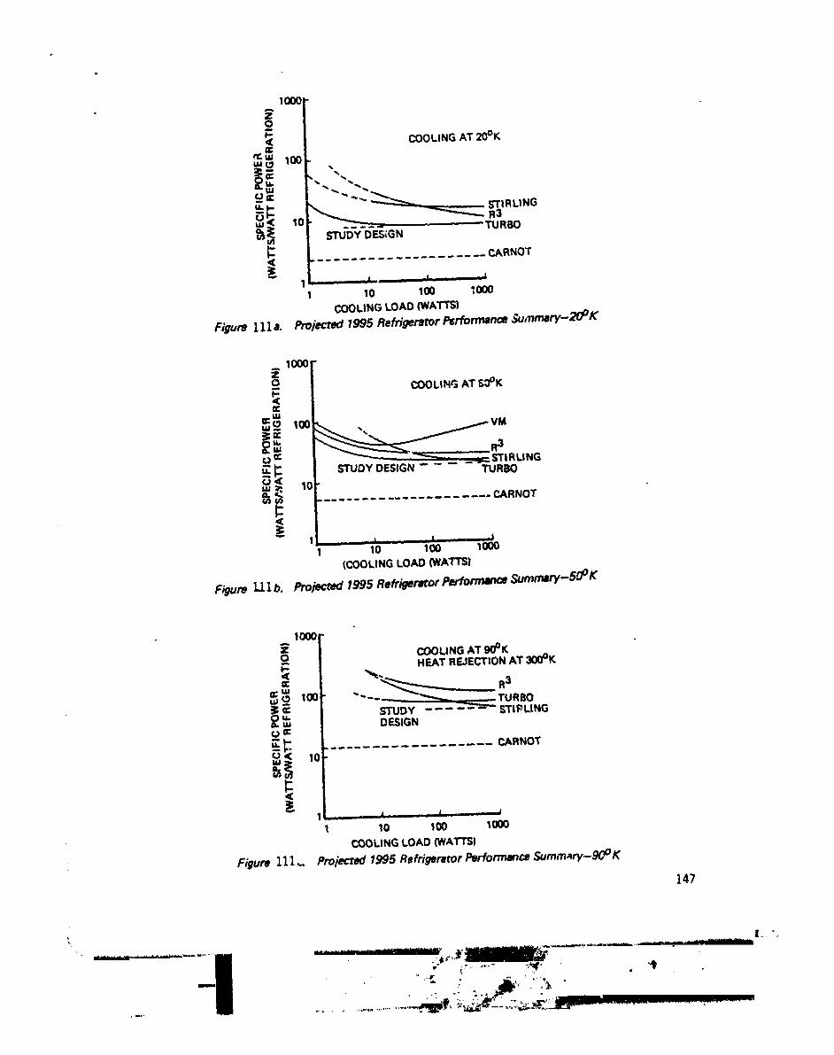
1000
COOLINGAT 2_0°K
'= .,
r ............... icARNOT_-" 1' ,I ' '
I 10 100 ;000
COOLING LOAD (WATTS)
Figure llla. Projected 1995 Refrigerator Perforr_nce Sumn_ry-20_K
,°[ COOLINGAT ._3°K
rj ¢=: R3,.--P. I e's',,,,.,,v,.,.......... ErIRLING
loll" ,,, u,._, _=ol_r_ TURBOI.LI
_ .................... CARNOT
1 10 100 1000(COOLING LOAD (WATTS)
Figure Ll l b. Projected 1995 Re_'ger_or Pej,fomtmnce Sumrnary-50° K
1000
COOLING AT 90°K
i HEAT REJECTIONAT 300°K
_. .... -""--_--_._, , TURBOSTUDY .... _ _'IPLINGu_ DESIGN
_m
CARNOT
1 .J- ¢...... I10 100 1000
COOLINGLOAD (WATTS}
Figure 111,., Proiecl_/1995 Refrigereror Performance Summ_ry-9OO K
]47
1985027415-159
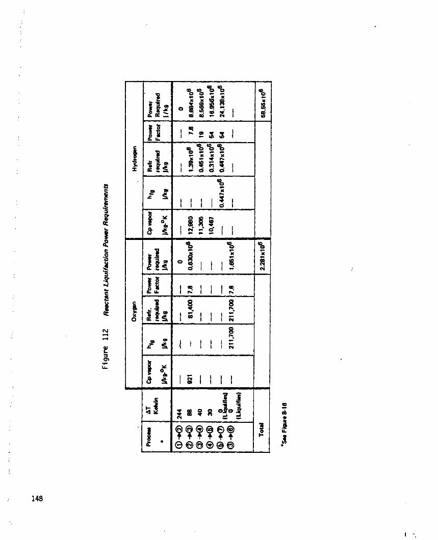
148
1985027415-160

and otherlossesislaunchedfrom earth,transferredto the H20 tank,flownto _hetree-flyer,processed,and flownback tothe stationas payload.
To eliminatelosseswhich would occur durin[spropellanttranslerfrom tank-to-tank,the OTV does not containa dedicatedset o( transiertanks. Rather,itdeliverstanks "kits"from the station-to-reactorand reactor-to-stationwhich
"plug-in"to the systems. An automated mating capabilityis requiredat thereactor.
The station power requirement evaluated was 150 kWe. Fuel ceil efficiency wastaken as 80%. BoiJof( was assumed to be 6%/6 months (#% H2, 2% O2). Enoughwater was flown up9processed, and returned as payload to fL:lfiIl the next mission'spropellant requirements. Figure l I# lists payload characteristics.
For the 150 kWe power option, 3# t of propellant is necessary for a roundtripmission. This is very nearly the reference 1 maximum propellant capabLlity.
$.8.7 Reactor Power Flow Distribution
The free-Ilyer electric power distribution is described in Figure ItS. Theelectrolyzer requires a total of 262 kWe. This produces a reactant flow rateequivalent energy of 2#0 kW. A price of It3 kW is paid for liquefying thereactants. The circulation and cooling, avionics, and control power requirementswere scaled (linearly) from an earlier study.
8.8.8 Mass/Volume Statement - Initial Operating Conditiocm
Figure ll6 describes the initial configuration of the system and identifies the massof each major subsystem. Figure It7 lists the mass and volume of these and othersubsystems. The dominant element is clearly the reactant/water mass.
8.8.9 Makeup Fuel Require.,nents
Over 3# t of propellant are required by the SBOTV for each roundtrip resupplymission. This loss, and others, are made up by launching water from earth to thestation on the STS, and from the station to the reactor on the SBOTV. Other lossesincJude boiloff and drag makeup fuel.
Drag makeup was evaluated for the contribution the elements of this study wouldhave in addition to the basic station. In the 150 kWe case, 95.5 m2 were added tothe station cross-section resulting in a I0 year dral_ makeup requirement of 136 :.)zwith a ballistic coefficient (M/CDA) of 1#06 k_m2_ an atmospheric density of 3.18x 10⁻¹³ kg/m 3 at 500 km, and an Isp of #50 sac. Drag at the free-flyer isnegligible.
Boiloff was assumed to be _%/6 months for LH2 and 2%/6 months for LO2.Advanced tank design would be required to result in these low rates. Figure 118summarizes the total makeup fuel requirement for the two options studied.
8.&t0 Lo_tics
The mass and volume of payload elements necessary for initial operating conditions(IOC) are tabulated in Figure It9. These values were used to evaluate SB OTVlaur,ch requirements Irom the station to the reactor. Shuttle launch capability was
149
1985027415-161

Figure 113 . Low Temperature Radiator Ch_t_cteri_zics
Subsystem Racli_or Rxliator Arsa MmTemp (K) Power
(KW) (m 2) " (t)
Electrolyzer 283 62 341 1.0
Dehumidifier 275 18 113 0.3
LH2 Liquifier 300 192 807 2.3
LO2 Liquifier 335 64 165 4.7
Figure 114 Tanker Pay/oed Mass
Mm(ram)
i
H20 or H2 & 0 2 230
H20 tank 2.3
(1% including structure)
LH2 tank 2.5
(10% including structure)
LP2 tank 4.1(2% includingstructure)
150
, i"
1985027415-162

I IREACTOR 150 kWeELECTRIC STATION
REO.i i i
_ ELECTROLYZER 263 KWAND DRYER
73
v"_ LIQUIFIER4O
i | i
I CIRCULATION=, ,, L_
" I AND COOLING 3
I AVIONICS
AND 2CONTROL --..-.--.
381KW
Figure 115 Free Flyer Reactor Power Flow Distribution
!I
!
151
i
1985027415-163
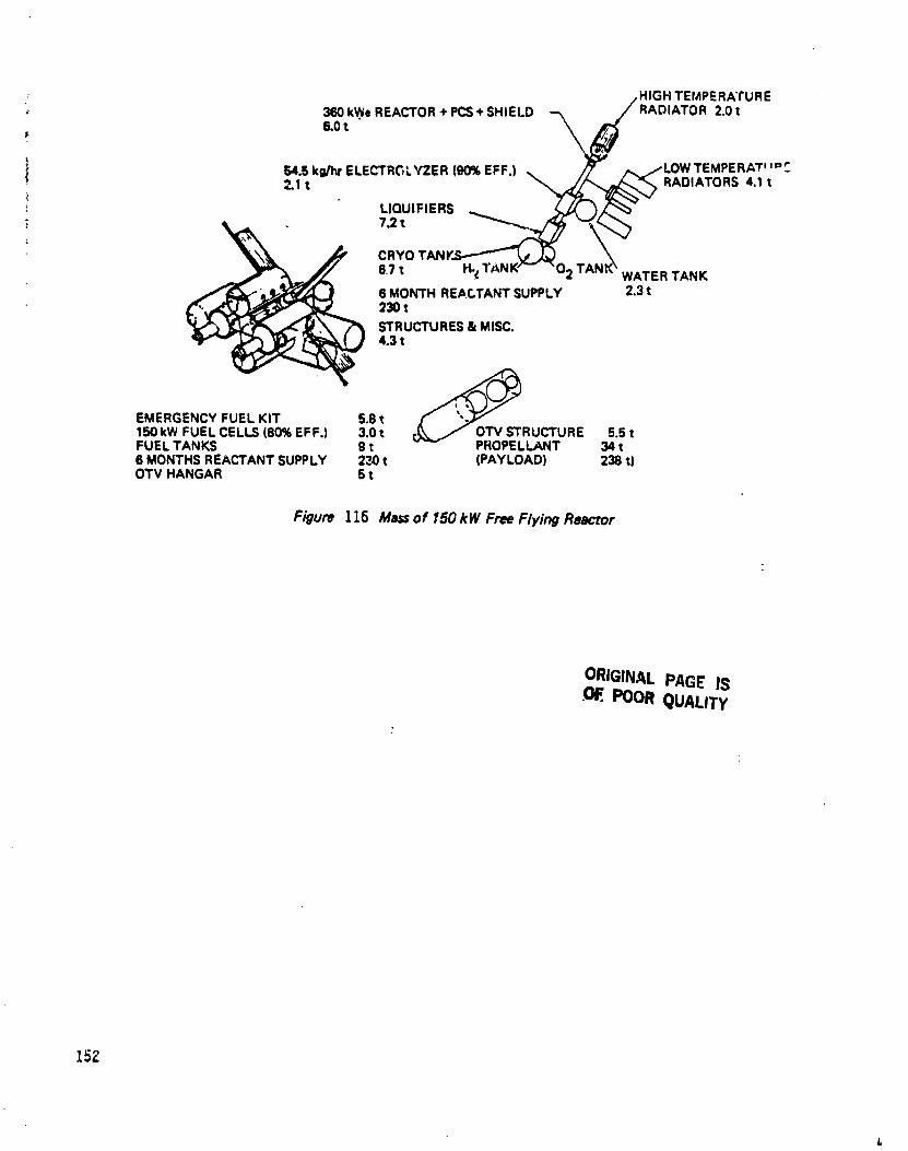
/ /HIGH TEMPERATURE
,_ 360kW. REACTOR+PCS+SHIELD --_/_ RADIATOR 2.Or6,0t
ELECTRGLYZER (90%EFF.) ,, ,_ /,,,/LOWTEMPERAT _'"_-
2.1t64"5kg/_r, _ 7",_-, _e_-__'\__'/ RADIATORS 4.1 tLIQUIFIERS ,__ _ )_'_
6o7t HoeTANW_" _'O2 TANK\ WATERTANK6 MONTH RE/_CTANTSUPPLY 2.3t23OtSTRUCTURES& MISC.4.3 t
EMERGENCYFUEL KIT 5.8 t15OkW FUEL CELLS(80%EFF.) 3.0t rv_,_" OTV STRUCTURE 5.5tFUEL TANKS 9 t PROPELLANT 34 t6 MONTHSREACTANTSUPPLY 23Ot (PAYLOAD) 238t)OTV HANGAR 5 t
Figure 116 Mass of 15GkW Free Flying Reactor
ORIGINAL PAGE ISPOOR QUALITy
15Z
1985027415-164

150 kWe 300 kWa
MIss Volume,_m3)/ Mass VolumelElement
it) Am. I-,,,LI 1.1 A,_.:
At Station
LH2 & LO2 or H20 230 -- ¢6U --
Tanks
LH2 2.6 366 5.2 732
LO2 4.1 229 8.2 458
H20 _.3 230 4.6 460
Fuel Cells 3.0 3 6.1 9
OTV Hangar 5.0 283 10.0 566
Miscellaneous 1.3 3 2.0 5.5
SBOTV 5.5 2G_ 11,0 414
At Reactor
Eleotrolyzer/Dryer 2.1 5.25 2.8 6.8
Liquifier
H2 5.0 12 6.0 24
0 2 2.25 3 2.2 4.5
Low Temp Radiators
Electrolyzer 1 341 m2 2 682 m2
Dryer 0.3 113 m2 0.6 2.:3 m2
2 Liquifier 2.3 807 m2 4.6 1614 m2
0 2 Liquifier 0.5 165 m2 1.0 330 m2
Structure 3.0 -- 4.5 --
Miscellaneous 1.3 3 2.0 4.5
LH2 & LO2 or H20 230 -- 480 --
Tanks
LH 2 2.6 366 5.2 732
LO2 4.1 229 8.2 458
H20 2.3 230 4.6 460I
Figure117: MassAnd Volumeof FuelCellSystem
153
i
1985027415-165
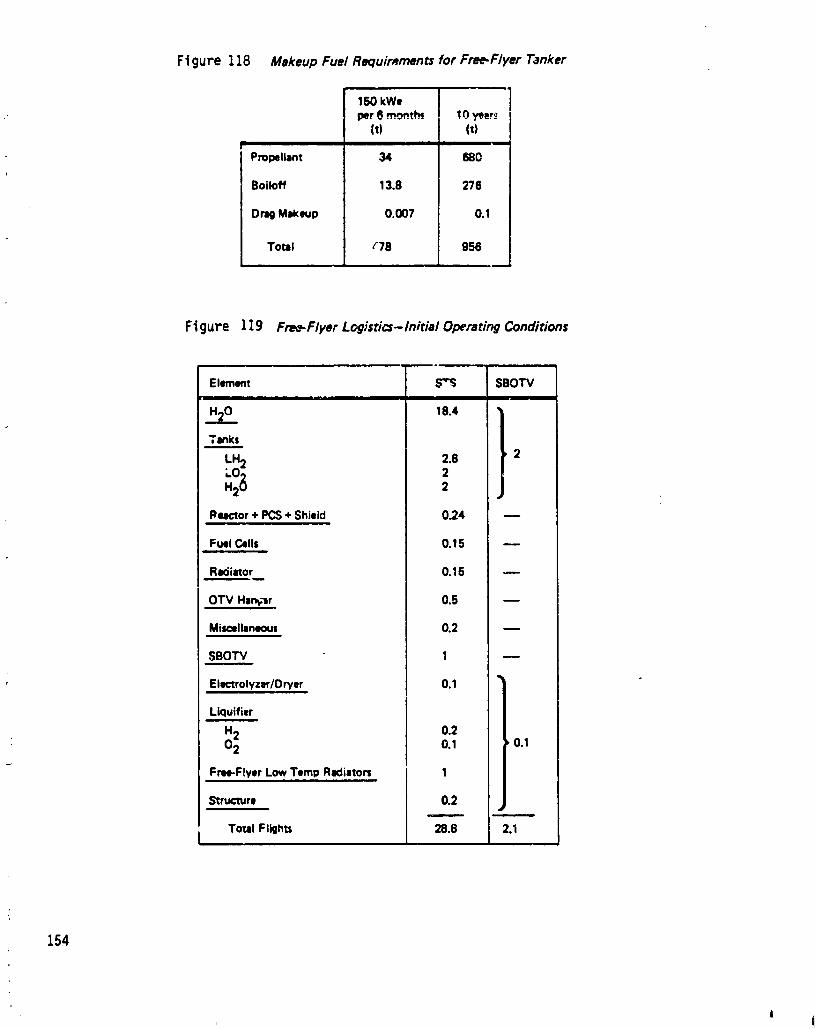
Figure 118 Makeup Fuel Requimmen_ for Free.Flyer Tanker
150 kWeper6 mo_nth_ !0 _er._
(t) It)
Propellant 34 680
Boiloff 13.8 276
DragMakeup 0.007 0.1
Total "78 956
Figure 119 Fre_Flyer Logistics-Initial Operating Conditions
Element _ SBOTV
H20 18.4 *
Tanks
LH2 2.8 , 22
Rqctor + PCS+ Shield 0_4
FuelCells 0.15 w
Raciiator 0.15
OTV Hmnt;jr 0.5
Miscellaneous 0.2
SBOTV 1
El_ctrolyzer/Dryer 0.1
Liquifitr
H2 0.20 2 0.1 ,0.1
FmPFeytr LowTempRKliator_ 1
Structure 0.2
Total Flights 28.8 2.II
154
1i
1985027415-166
0
iassumed to be a maximum of 25 t or 300 m _1to a 500 km station, Load factors
' were evaluated by determining whether the mass or volume of an element "filled"the shuttle's paylead bay. For example, water was mass limited while the tankswere volume limited. SBOTV loads were determined by mass only. Figure 120 liststhe number of launches required for each element for initial operating conditions.
To replace propellant and other losses) water must be launched from earth to thestation. Based on the load factors described above) two 5TS flights are requiredevery six months for water delivery and #0 5TS flights are required over the l0year system life. Figure 120 lists the lifetime logistics summary for the free-flyerconfiguration.
8.8.11 Reduced LoT_'ti_ Alternatives
Because of the magnitude of the reactant requirement discussed above, multiple" free-flyer configurations were considered. One configuration considered was to
place N (two or more) free-flyers in orbits of equal altitude but separated by 360/N• degrees. As a point design five equally spaced free-flyers in 700 km orbits was
selected with a 150 kWe station power requirement. The time between transferopportunities with a tree-flyer was I02 days (510 days between transfer with anygiven free-flyer). This reduced the V required by a factor oi 2.7. Although thisapproach reduced the number of cumulative STS flights by 18) it increased thenumber of OTV flights by 23. Figure 121 lists STS logistics for this conliguration.Because this configuration did not significantly alter the logisti_s of the free=flyer,multiple reactor configurations were not further considered.
The possibility of using an unmanned, shuttle-derived launch vehicle with greaterpayload capacity than the STS was considered, This launch vehicle is shown inFigure 122. The Unmanned launch Vehicle (ULV) uses STS propulsion) but not anorbiter, The engines and avionics are contained in a recoverable module under theExternal Tank. The payload is positioned above the tank. The baseline two-engineconfiguration has a payload volume 27 m long and 7.6 m in diameter, This is threetimes the STS cargo volume, The payload cap3bility is 5# tonnes to 500 kmcircular orbit) which is 2.16 times the $TS payload projected to that altitude.
The larger available volume allows all flights to be mass-limited rather tha_volume-limited, In the 150 kWe case) the number of launches is reduced from 29 to10,5 for the initial operation, The 10 year cumulative launches are reduced Irom68 to 24.
The cost per flight of trc '..'LV is estimated to be $66 million) compared to $100million for the ST$, Thus the cost advantage for the ULV is more than four %oone.
Note that the number of launches for the other options would alamobe reduced bythe ULV, The on-board) man-rated tether) and instrumented tetl_er _*;^-" vo,dd1 requi_e 0.6) 1.6) and 1.2 ULV flights respectively.
Three alternatwes for transporting reactant from the reactor to the space stationare chemical) resistojet) and ion propulsion OTV's. For comparison purposes, thepayload requires more V than an impulsive burn. Figure 123 gives details of thethree options.
" 155, i
'{
1985027415-167

8
" Figure 120 Lifetime Logistics for Free.Flyer Reactor
IOC Life UfetimeTotal
• m
s'rs 29 40 69
SBOTV 2 20 22
Ftg,jPe 121 Logistics for Five Free.Flyer Reactors
Logistic=for IOC
Numberof STS flights 36
Numberof OTV flight= 6--10
Numberof OMV flights 5
Cumulativelog_stJc=
Numberof STS 50
Numberof OTV 40-50
Numberof OMV §
Figure 123 :Alternative Propulsion Modes
Elem_mt Unit Chemical Rmistojet Ion
Propeliint m Oxwen-Hydrogen Hydrogen ArgonPWloKImm ton= 238 238 2"38Tol_l maa tom 284 284 284Specificir,,)ube lecond$ 480 850 2500Miuion AV m/= _ 600 848 848
Massraim rio mi/m f 1.136 1.1071 1.0352Procwllanttomb tor:l 34 27,5 9,65
Propulsionspecificpower W/kg 25830 60 28.5Propulsiontotal power MW 310 1.11 1.035
Thrust N 132000 222 26Bumtime dew .014 8.5 105
156
| ,
1985027415-168
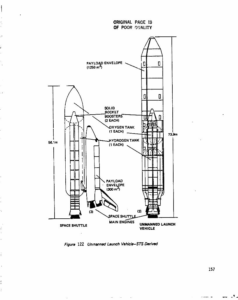
ORIGINAL PAGE ISOF POOR OUALITY
rlPAYLOAD ENVELOPE 0( 125(, rr _')
Figure 122 Untnanned Launch Vehicle-ST$ Derived
157
1985027415-169

I
System Summaryg.9 Trade!
The results of the trade studies described in Sections 8.6-8.8 above are summarized• in Figure 124. Because of the large tanker size and startup fuel inventory, thei
free-flyer reactor option requires 29 orbiter flights to get the system star_ed.Once the system starts up, this option still requires two round trip OTV flights peryear for fuel transfer plus four STS flights per year to provide propellant to theOTV. Selecting this option would result in considerable space station traffic andessentially a dedicated orbiter and orbital transfer vehicle for fuel production anddelivery. There are alternatives avai/able for reducing the number of shuttleflights) but these involve either a new launch vehicle or more OTV flights and donot change the basic conclusions - that the free-flyer reactor involves many flightson a continuing basis.
The boom-mounted reac'_or system requires 1.3 STS flights to place all theequipment in orbit. This includes not only the power generation equipment) butalso the end of life booster vehicle and an emergency power kit. An orbitalmaneuvering vehicle is already being planned as a part of the space station system,so it can be expected to be in place by the mid-1990's. It also seems reasonablethat some form of emergency power kit will be available during the early spacestation period. As Figure 99 shows) without these two items the entire boom-mounted reactor power system can be delivered to the space station in a single STSlaunch. The additional payload delivery to orbit for drag makeup over the reactor
: lifetime i_ trivial for the boom=mounted reactor case, even including that requiredfor the space station itself.
The tethered reactor requirements lie between those of the other two cases. Atethered reactor system with an instrument=rated shield can be delivered in abouttwo full STS flights and one OMV flight, with another gS_ kg/year of water to beused for orbit makeup propellant. A man-rated shield would increase the mass by17)800 kg, or 0.7 full orbiter bay equivalents) for the possibility of some mannedmaintenance of the power generation system.
8.10 High Power
The data collected for this study have been generated parametrically. When aspecific power level was needed, such as to generate the mass and volume data ofthe last four subsections of this report) a space station power of 150 kWe wasselected. To investigate the three system configurations at a higher power lev_l,the same trade studies were performed at 300 kWe. The results are shown inFigure 125.
The power range of the. reactor core used for this study extends to about _ M Wt.At 5.1% efficiency) which is projected for current thermoelectric conversiontechnology) this limits the electrical output of a single reactor to about 200 kWe.In the _ree-flyer case at 150 kWe, this necessitated treating the reactor as a pairof baseline reactors on a single space'craft. For the higher power levels consideredhere) a higher eff;,ciency power conversion system was selected. This was taken tobe a Stifling cycle for this report) although a Brayton cycle should yield verysimilar results. With a power cenversion efficiency of 25%) the reference reactorwith a Stifling engine is then able to provide 1000 kWe, instead of the 200 kWeprovi_f _by the baseline thermoelectric system.
158
I
1985027415-170
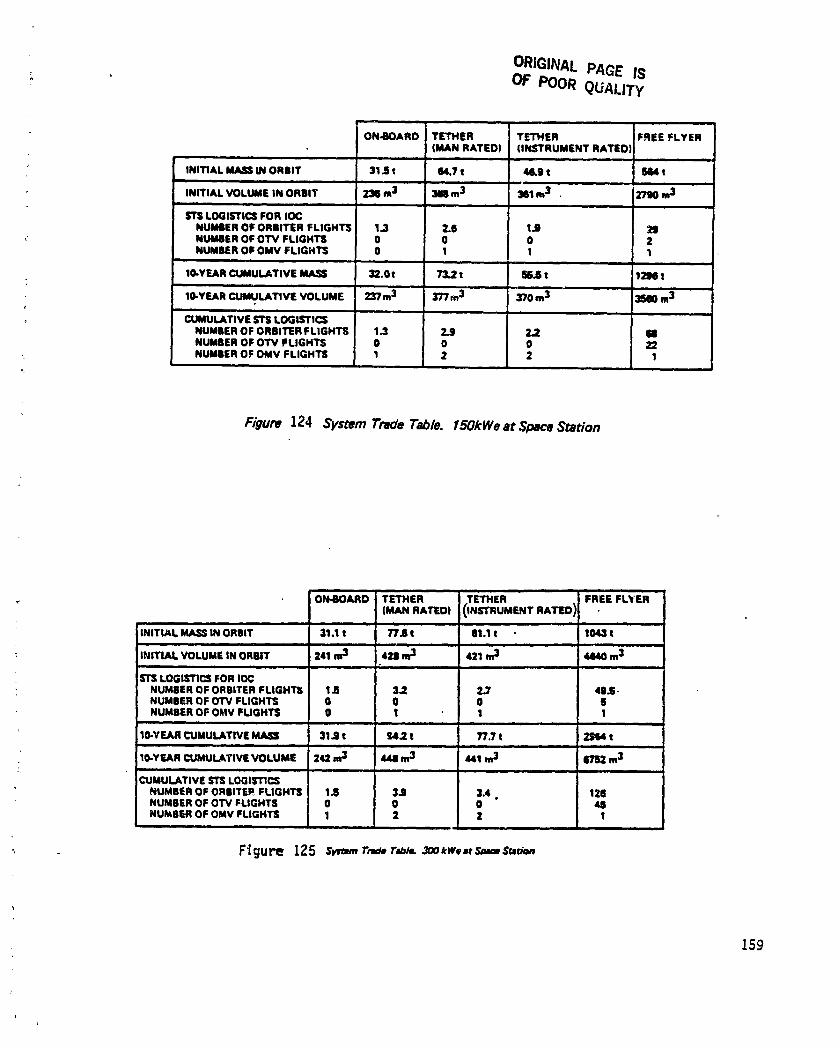
ORIGINAL PAGE ISOF POOR QUALITY'
ON-BOARD TETHER TETHER FREE FLYER(MAN RATED) IINSTRUMENT RATED)
; INITIAL MASS U_IORBIT 31-9t 84.7 t 4S.B t _ t
INITIAL VOLUME IN ORBIT 2216m3 _ m3 381 m3 • 2790 m3J ,i , •
STS LOGISTICS FOR IOCNUMBER OF ORBITER FLIGHTS 1.3 2.6 1.9 2_D
_ NUMBER OF OTV FLIGHTS 0 0 0 2NUMBER OF OMV FLIGHTS 0 1 1 1
10-YEAR CUMULATIVE MASS 32.0 t 73.2 t SE.S t 1_ t
tO-YEAR CUMULATIVE VOLUME 237m 3 377 m3 370 m3 35B0 m3
CUMULATIVE STS LOGISTICS
NUMBER OF ORBITER FLIGHTS 1.3 2.9 2.2 ImNUMBER OF OTV FLIGHTS 0 0 0 22NUMBER OF OMV FLIGHTS 1 2 2 1
Figure 124 SystemTradeTable. 150kWeat SpaceStation
ON-BOARD TETHER TETHER - FREE FLYER
(MANRATEO)0NSr.UMZNTnA_O)I;,IT_L,_sINOnBll.... 31.;, n_, 611, 10_,INITIAL VOLUME IN ORBIT 241 m3 42S m3 421 m3 44140m3i ill i •
STS LOGISTICS FOR IOC' NUMBER OF ORGITER FL|GHTS I Iz 3.2 2.7 4|.S.
NUMBER OF OTV FLIGHTS 0 0 0 SNUMBER OF OMV FUGHTS 0 I 1 1
:l , i= , H,
10-YEAR CUMULATIVE MASS 31.9 t t54.2 t T/'.7 t 2S114t,n i i
10-YEAR CUMULAllVE VOLUME 242 m3 4411m3 441 m3 _ m3,m i . |l i
CUMULATIVE STS LOGISTICS
' NUMBER OF ORBITER FLIGHTS I-9 3-9 3.4 • 1211NUMBER OF OTV FLIGHTS 0 0 0 48NUMBER OF OMV FLIGHTS 1 2 2 I
F'igure 125 sv=_.r_ r=_/.zoo,w. _ s_ms.._=n
159
1985027415-171

The boom-mounted reactor supplies 306 kWe to the transmission lines. These linesare assumed to be two sets of four wires each, supplying three-phase aJternatint_
. current power at 1!5 volts. The optimum boom length is 55 meters, with thecomplete transmission line set weighing 650 kg. The mass of the reactor and powerconversion system is 2600 kg and the shapedfour=pi shield mass is 16,500 kg. Eventhough the 300 kWe reactor is closer to the space station (55m) than the [50 kWereactor (70m), the shield mass of the high power case is somewhat lower. This is aconsequenceof the higher efficiency assumed !or the high power case; 153 kWe isgenerated from 3000 kWt at 5.[% efficiency, while 306 kWe is generated Irom only1224 kWt at 25% eftidency.
The radiator mass is 850 kg for the boom-mounted reactor. This is for a primaryradiator that rejects 887 kWt at 6_0 K and a secondary that radiates 31 kWt at 3#3K. The boom structure weighs 160 kg.
The total mas_sin orbit for the 300 kWe boom-mounted reactor is 3t,[00 kg. Asmentioned above, the reactor, power conversion system, man-rated shield,radiator, transmission lines) and boom structure requires one full shuttle launch.The emergency power kit and OMV requires 41% of a second flight.
The 300 kWe tethered reactor power output is _]6 kWe, or 1664 kWt. Theinstrument-rated shield mass is 5610 kg and the man-rated shield mass is 17,100 kg.The radiators weigh 890 kg for the 640 K primary and 270 kg for the 3#3 Ksecondary. The reactor and power conversion system mass is 2900 kg.
Since the output power is twice that of the reference case, the reactant flow rateis doubled. Assuming linear scaling of the electrolyzer fuel cell, and fuel storagetank masses, these quantities are doubled. The water hose diameter is [.26 cm, sothe water Lnthree hcsesweighs 1],200 kg.
The total mass for the 300 kWe tethered reactor with a man-rated shield is 77,600kg, which requires 3.2 shuttle launches. For an instrument-rated shield, thesenumbers are 61,100 kg and 2.7 shuttle launches) respectively.
The free-flyer reactor with a Stifling cycle requires 2880 kWt to produce 720 kWeat the reactor for 300 kWe of space station output. The reactor and powerconversion system mass is 3500 kg and the shield mass i_ 780 kg. For each fueldelivery) two orbital transfer vehicles with the same specifications as thosedescribed in Sect[on _.8 are used. The total number of shuttle launches is aboutfifty for initial star[up) and over one hundred over the ten-year lifetime. The totalnumber of OTV flights is _5. The traffic rate is four orbital transfer vehicle roundtrips and 7.65 orbiter flights per year.
1985027415-172

0
9.0 SYSTEM REQUIREMENTS
The study/anaiysi_ has resulted in establishing requirements for the nuclearelectric power system) the space station) and the space transportation system.Since the electrical power system with the reactor as the energy source was to beconsidered with any candidate conversion device, requirements must therefore begeneral enough to encompass any of the conversion systems with any of the reactorplacement configurations. The requirements for the various combinations andconfigurations will be grouped as much as possible so as to identify and treat all ofthem.
9.1 Nuclear Electric Power System Requirements
Figure 126 showsthe tabulation of requirements for the nuclear electric system forthe three conceptual designs:
o On the space stationo On a tether to the. space stationo On a free-flyer spacecraft
The grouping shows the static conversion systems and the dynamic conversionsystems. Transmission line requirements will depend upon whether the line is DCor AC and whether the conversion equipment output is DC or AC. The staticconversion equipment output is DC and power conditioning will have to be suppliedto convert to AC or to another DC voltage level. Dynamic conversion equipmentoutput is AC and can be designed for some levels and frequencies compatible w;.ththe transmission line. For high frequency, power conditioning will be requiredsince the machines generally do not operate at the speeds required.
o For Brayton cycle or Rankine cycle:Generator RPM = (Frequency in Hz) x 60 for a single pole pair(equivalent)At 20,000Hz, thegeneratorrotationalspeedis:
1)200)000 RPM for l pole pair120,000 RPM for l0 pole pairs
o For 5tiriing cycle:Lineargenerators)whichwould be pairedwitha Stirling(reciprocating)
engine,are limited in frequency. To attain higher Irequencies wi_h the, Stirling engine, the reciprocating motion would have to be converted torotary motion to drive a conventional circular generator. An alterna-tive would be to convert the frequency to a higher one with powerconditioning.
The electrical power system reactor, shield) and conversion equipment is to be
:! designed for placement in a long life orbit after damage or expended life.Provision is to be made for severing the reactive components from the non-
,,i radiative portions at a convenient interface. The replacement equipment shall be, reconnected at the interface."1
To provide monitoring and control of the reactor) a separate and self-containedpower supply shall be provided. This power supply shall be highly reliable and shallprovide that any malfunct,:on of the reactor or conversion equipment shall be fail-safe. The power supply may be an energy storage device with recharge capability,
161
|I
1985027415-173

ConfigureUon Conversion(P_ment) S',ltic Dynan, ic Tran_mi_ion Tl_m'4i Controt
I | I IN I
At CG Full 4-PI shield for 5.72 mrem/hr
(With RFC) Condition to DC Providevoltage end Provide active coolingfrom AC, or frKlUenCydinmtly _op from ¢onvecsionih'nenlta DC for at distribution equipment to highelectrolysis voltage and frequency tampamtum radiators.
........ Placeradiatorsaway(No tr|nsrn;nion line) from station equipmnta,
traffic, end EVA areasProvide counter-motion to canceltorque or
. vibration
On stru_ Shaped 4-PI shield for 5.7 mrem/ Provide high-voltage Provide rsdiator_ atrural boom hr toward station and 209 rem DC or AC trans- conversionequipment
at 30 mmrs away from station missionline,compatible withearth's plasmaeffect
Provide Provide radiatorsatcounter-motion conversionequipmentto ¢encel torqueor vibration
(With RFC) ' Condition to DCElectrical from AC orTransmission generate DC for
electrolysis
(With RFC) Provide H20 ind H_ Provide radiator; atH20/H_/O 2 end 02 linesto fuel- ¢on_rsion equipmentTr-ansrnTssio-n cllls in station, end for electrolyzer
Elecl_olyzer near on boomreactor (Noelectricaltransmissionline)
Figure126 NuclearElectricSystemRequirements
162
1985027415-174
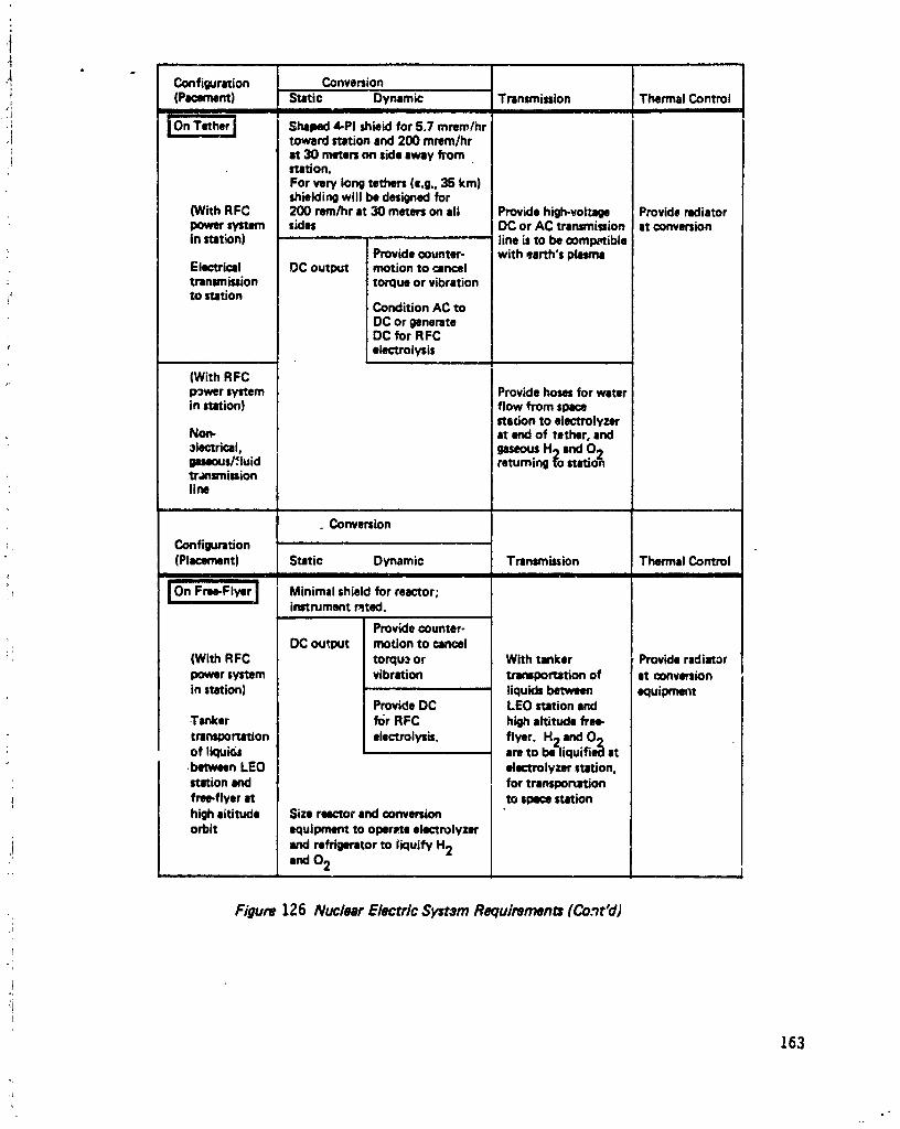
l
i_ Configuration Conversion; (Pmnt) Static Dynamic Transmission Thermal Control
• i I
; j'C)nTether j Shaped 4-PI shield for 5.7 mrem/hr.! toward ration and 200 mrsm/hr
it 30 mete. on side away fl"om'* station.
For wry long tethers (e.g., 35 kin)shieldingwill be designed for
(With RFC 200 rMn/hr It 30 meters on all Provide high-voltage Provide radiatorpower system sides DC or AC transmission at conversion
in station) line is to be compatibleProvide counter- with earth's plato
Electrical DC output motion to canceltransmission torque or vibrationto station
Condition AC toDC or _nerateDC for RFCelectrolysis
(With RFCpower system Provide hosesfor waterin station) Iflow from spl(_!
stadon to eiectrolyzerNon- at end of tether, and3iectrical, .gaseousH 2 and 0 2gimous/:luid i ratuming to stationtransmission
• line
. Conversion
_, Configuration(Placement) Static Dynamic Transmission Thermal control
_11
" _ Minimal shield for reactor;instrument r_ted.
Provide counter-
. _ DC output motion to cancel(With RFC torqu_ or With tanker Provideradiatorpower system vibration ttamportation of at convmionin station) liquids between equipment
Provide DC LEO station and
Tanker for RFC high altitude free-
transportation electrolyzb, flyer. H2 and 0 2of liquk_ are to be liquifie¢l at
between LEO dectmlyzer =ration,station and for transportation
,! free-flyer at to spacestationhigh lititude Size reactor and conversionorbit equipment to operate electrolyzer
,i =rid refrigerator to liquify H2and 0 2
, Figure1;>6NuclearElectricSystemRequimmenB(Co._t'dJ
1
163
1985027415-175
and shall be rated for 21 days of operation. An alternative power supply may be anAPU.
Safety Requirements - The nuclear reactor, shield) and conversion equipment shallmeet safety requirements given in guidelines and nuclear safety requirementsdocuments. A list of recommended documents and guidelines is given inFigure 127.
Environment - The nuclear electric power system shall operate in all theenvironments associated with the altitude and orbits specified. Of special interestare the specific items such as the Earth's plasma) radiation) micrometeoroids) andcontamination due to exhausts) outgassing, and ejecta.
To survive the launch environment the nuclear e)ectric system must be mountedand supported to protect tubing and thin structures from vibration.
9.2 Space Station Requirements Due To Nuclear Electric Power System
The space station requirements due to the nuclear electric power system areinvolved with the design and operation of the space station.
9._..I Mounting and Insta/lation
Provision is to be made for mounting the nuclear reactor) shield) conversionequipment) radiators) power equipment) and the control and monitoring compo-nents. Also included is the emergency power system and mounting) so as not tocompromise the design for reentry in emergency conditions or after a coolingperiod.
Installation OptionsA) On space stations - A boom is to be provided to support the reactor) conversionequipment, shield, power conditioning, radiator, and transr_'_sion line when thereactor is mounted on the station. The mount and structure =re to be designed soas to facilitate maintenance) repair, and replacement. Provision is to be includedfor disposal of the reactor to a high altitude orbit.
B) On tether - A tether is to be provided to support the reactor) conversion: equipment, shield) power conditioning) radiator) and transmission line. For
electrical transmission) the tether shall be the electrical cable assembly which cansupport the operational loads. For non-electrlcal transmission) the tether shall besuitable hoses for transporting water to the electrolyzer and gas hoses fortransportin 8 H2 and 0 2 to the station. Reinforcements may be used) if required.The tethered platform which contains the electrical power system components
: shall also have redundant attitude control and communication/telemetry equipmentwhich is powered by the on-board electrical system. Provision shall be made in thedesign for mounting a propulsion engine for parking the reactor at a high altitude.This shall be redundant so as to be reliable.
C) On a free-flyer - The free-flyer vehicle shall include mounting of the electricalpower system components, and shall have on-board propulsion attitude control) andcommunications. These systems shall be red_J:dant so as to provide _eli.'-_'teoperation.
J64
t,
1985027415-176

t
!......... !* OSNP-I, Nuclear Safety Criteria and Specifications for Space Nuclear Reactors
• 10CFR20, Standards for Protection Against Radiation
: • 10CFR50, App. A, General Design Criteria for Nuclear Powerpiants
i • DOE Order 5480.1A, Environmental Protection, S_fety, and ,4ealth Protection ,i Programs for DOE Operations
I • NHB 1700.7A, Safety Policy and Requirements for Payloads Using theI •Space Transportation System (STS)
i
i1' 1':_ JSC 11123, Space Transportation System Payload Safety Guidelines Handbook
\
, Figure127 NuclearSafetyRequirementsDocuments
165
1985027415-177

- 9.2.2MissionOperation
Since d-_ mission operation is controlled by the space station operators and groundcontrol) the traffic control near a reactor) the conversion equipment, and theradiators will be under the operator's jurisdiction. It will be required that trafficnear the harmful components be monitored c_refutly since there are no lane
i markers in space. The _ight operati_, personnel will control tr_ ffic so thatvehicles do not venture too close to the reactor for any excessive length of time.It will be the responsibility of the operators to comply strictly with safetyregulations.
Maintenance and repair are the ,esponsibility of the space station maintenancecrew. Persons servicing the nuclear system shall be schooled and trained for_.amiliarity with nuclear technology and the sa2ety regulations. In the event of anaccident to the reactor in which a dangerous level of radiation is expected,provision will be made for a "radiation-proof" shelter in which _ersonnel can isolatethemselves safely for an emergency period.
The control of remote equipment on tethered platforms or on free-flyer will beunder control of the space station traffic controllers. Requirements applicable tothe nuclear electrical power system will be prepared for and _ ;bmitted to thetraffic controllers. Orientation of spacecraft radiators wi.'l be controlled by themission operators who crient the space station. Communication with the remotespacecr_.'t will be controlled by the traffic controllers.
When station keeping or attitude control is requ£red, it is the responsibility of thespace station operating personnel to provide it.
Installation of EPS equipment will be the responsibility of the space statinnmadntena,_cepersonnel. Provision will be made for the installation of addition&[ ordifferent electrical equipment throughout the vehicle. Growth wilt be provided forwhere possib[eo Cabling will be fastened securely to the cable run structure so asto prevent buckling or loosening of the structural members under fault conditions.Interface connections specified by *.he electrical power designers will be provided.
9.3 STS Re_luirements Due To Nuclear Electric Power System
STS requirements due to the nuclea_ electric power system are"
o To provide an uncontaminated environment free of debris which can affect| the electrica_ system.
o To provide orbital vehicles for placing the reactor) shield) altd conversionequipment into position on the boom or tether.
o To provide an OMV for moving the reactor and shield into a high, long-lifeorbit aiter the end-of-life or in the event of a malfunction.
o To provide an OTV ,or transporting liquids between the space station and the
.'I free-flyer vehicle., o To place the free-flyer in _tsspecified orbit.
.!
-I
i
i 166I
1985027415-178
ii
j o
"" lC.O (. _ ,,iC].USIONS
:! This study identifies the applicability of a nuclear reactor electrical power systemI
:i to the space station. At power levels above 100 kWe, and primarily at the levelsi' between 150 and 300 kWe, the nuclear reactor power system has a competitive_ position because it offersthefollowing:-i
.', Energy density which remains high as the power levels increase. Since there is no, requirement to provide for recharging of batteries, fuel cells, flywheels, or thermal
,' salts as forsolar panel oriented systems, the system weight position improves when:'; compared with solar powered systems."i
10.1 Reactor Viability ._, A Source Ot High Power
' When analyzing the loads, we found that loads larger than the originaI NASAStandard Reference Set were feasible. Electrical loads can be identified to as highas #00 kWe. Recent analyses by NASA and industry showed that tne housekeepingloads Ix e grown to 40-50 kWe and additional high-power loads have beenuncovere_. From this we can assume that the space station loads will be gre=terthan we were originally given in the mission set. Historically, !oads alwaysincrease then the preliminary design becomes a detailed design and the loads areex_.mined indepth.
10.1.1 Mission Power Requirements
Because it is a compact energy source, the nuclear reactor is an excellentcandidate for high power applications. As the loads grow, the reactor�shield�conversion package remains essentially at the same level of weight within aspecific range. In manned space stations tbe total sp_:ecr_t loads are higherbecause the life support system power level is substantial.
Analysis of the mission loads shows that the,'e are numerous scientlfi _ andcommercial load.-; which require high pow_.L- levels. The commercial loads arecharacterized by g.-owth with time as the market develops and the product siJesincrease. In Section 2.1 the &_.tails of the loads were defined.
10.1.2 B_..fil_
With a nuclear reactor energy source the high power requirement can be fulfiUedwith minimal penalty for drag and cdentation. The therma radiators can be
streamlined into the orbit plane _o as to reduce drag, thus _aving station keeping(orbit maintenance) fuel. Because of its independence from tt,3 sun, xhe lack of aneed to recharge a thermal storage element will reduce the power system to thesize of the lead requirement, plus losses and degradatio, I,
For those l_ads which require heat directly, the therrr,_ interface can bcestablished ._othat the heat is not derived from heat-to electr.city-to heat.
i0.2 RegenerativeFuel Cell SubsTstem Attrac*J__,ness
Of the options examined, the regenerative fuel cell is an attractive candidatebecause it avoids some problems when it is linked directly to the reactor power. Inthat option, the reactor will power the electrolyzer, which separates the H2 and 0 2
167
1985027415-179
from the water, the fuel cell output. It is much simpler to transmit the liquid andgases than to cope with an electrical power transmission line operating in thehostile environment of the Earth's plasma and contamination from outgassing,exhaust, and debris.
The fuel cell is an excell-nt candidate for en__r_y storage as well as a prime powerconverter. I£s efiiciency is high, has operational background, is relatively reliablebecause it has beer, !mproved over the years of use) first as an open-cycle cell,then as a clo=ed-cycle system in the Apollo program.
10.3 Evaluation of Options
Three reactor/space station configurations were evaluated and the economicsparameters show that:
o The reactor on the structural boom requires the fewest $TS flights.o With t_m reactor opera__ng in a 300-year orbit requires 68 shutt:e f;_ghts, for
a 150 kWe power load. The ;uantity of flight_ is influenced by the provision; for fuel for *_ tanker vehicle.
o V/hen the _c.( is on a fixed boom or on a tether, the reactor is closeenough to +t,, space sta£1on and at a low altitude where it requires boostingtc 1,ighe-, lonB-life orb,t.
I
1985027415-180
I1.0 RECOMMENDATIONS
A, It is recommended that an analysis be made of concepts which allow for spacestation designs to provide for growth in the power system with time. The on-boarddistribution system should be designed to accommodate AC although the earlystation may revert to DC. To change from solar generated power to nuclear
. generated power maximum use should be made of the original on-board electricalpower system equipment, and how the original equipment can be enlarged by addingmodules.
The design and operation should be examined to determine how the original solararray can be disposedof or stowed when the growth power system is substituted. Ifstowed_it can be the emergency power system.
B. Since SP-iO0 reactor design is not directed to m,mned spac_ stations, thereactor and shield technology will have to be researched to develop concepts ofdisposal and reentry. Ventirg will have to be changed for the man-Fated design.This will affect the reentry package design.
C. A more detailed study with quantitative data should be made of some of thebypassed options. Because of the absence of the electrical transmission line, theEPS design would be simple provided that there is a simple way to transfer the heatto the thermal control radiators.
l
] D. The placement of the reactor in the high-altitude orbit should be given afurther analysis for reduction of the quantity of trips by increasin[; the number of
;] tankers, and increasing the number of free-flyers with reactors, electrolyzers, andI refrigerators.
l:] With a larger transport vehicle the quantity of operational flights _dso could be
reduced. Combining the larger tankers with the increased number of free-flyersmight decrease the number of shuttle launches in a 10-year cycle to an acceptablequantity.
A number of shuttle flights are involved with providing water as makeup for thesystem when the tanker uses a large quantity of fuel. An analysis can I_, made ofthe logistics of transporting the water to orbit orl a space-available basis. Thiswould reduce _he assigned cost for the power system.
169
J
1985027415-181

12.0 REFERENCES
| 1. Mission Requirements Working Group Report, NASA Langley Research
.| Center, October 7, 1983.
| 2. (Number Not Used)
__ 3. Space Station NeedsI At_ributes_ and Architectural Options Studyt .'=inaIReport, D180-27477, Boeing Aerospace Company, Seattle, WA, April 21,1983.
4. 5pace Production c_ Semiconductor Crystal, Microgravity ResearchAssociates,Inc.,Huntsville,AL= February1983.
5. D. Chandra and H. Wiedemeier,3. of CrystalGrowth 57:1(159-76),March1982.
6. Agreement Between the NationalAeronauticsand Space Administrationand' McDonnel Douglas Astronautics Company for a 3oint Endeavor in the Area of: Materials Processing in Space, 3anuary 25, 1980.
7. C. Coral,It, Av. Week and Space Tech., May 31, 1982.
, g. 3.C. Lowndes, Av. Week and Space Tech., Octoberl9, 1982.
9. Space Transportation System User Handbook, NASA, 3une 1977.
10. (Number Not Used)
: It. S.J_ace Station Prooulsion Requirements Stud},, Boeing Aerospace Co.,Contract NA53-23353, Release in October 1984, Boeing Document DIa0-28264-1
12. (Number Not Used)
13. Space Transportation System Payload Safety Guidelines Handbook, 35C1_123, NASA 3ohnsonSpace Center, 3uly 1976.
14. Space Planners Guide USAF
15. Safety Polic_"and Requirements for Payleads Using the Space TransportationSystem, NH5 1700.7A, Deck_tuber9, 1980.
i 16. Analysis of Regenerative Fuel Ceils, Boeing Aerospace Co., Contract NAsg-i 16t5l Mod. 7, Boeing Document D180=27160-1, December 1982.
17. 3.A. Helle:, T.A. Moss, G.3. Barna, Study of a 300 kWe Rankine CycleAdvanced Nuclear-Electric Space Power System, NASA TMX-1919,November 1969.
lg. Development of Thermal 3ontrol Methods for SpecialL -d Components andScientific Instruments at Very Low Temperatures, Rockwell-lnternationalDocument 5D76-SA-0077, May 1976.
170
_1
1985027415-182

i9. L on_ Term Crvo Stora,_e Studv_ Final Program Review: Martin MariettaDocument MCR-83-62t, September20, 1983.
20. Future Orbital Transfer Vel_lcle Technology Study, Boeing Aerospace Co.,NASA Contractor Report 3536, Contract NAS1-16088, May 1982.
21. Orbital Propellant Handling and Storage Systems for Large Space Programs,Genera/Dynamics, Contract NAS5-15305, April t978.
22. Space Operation Center, Boeing Aerospace Co., Contract NAS 9-16131,Boeing Document DIS0-26785, 3anuary 1982.
I i71
l"I
1985027415-183