Embed Size (px)
Citation preview

8/10/2019 MS150054_02E.pdf
http://slidepdf.com/reader/full/ms15005402epdf 1/155
Operating InstructionsDiesel engine
12 V 4000 G73
16 V 4000 G73
Application group 3B
MS150054/02E

8/10/2019 MS150054_02E.pdf
http://slidepdf.com/reader/full/ms15005402epdf 2/155
Printed in Germany
© 2012 Copyright MTU Friedrichshafen GmbH
This Publication is protected by copyright and may not be used in any way whether in whole or in part without the prior written permission of MTU Friedrichshafen GmbH. This restriction also applies to copyright, distribution, translation, micro‐
filming and storage or processing on electronic systems including data bases and online services.
This handbook is provided for use by maintenance and operating personnel in order to avoid malfunctions or damageduring operation.
Subject to alterations and amendments.

8/10/2019 MS150054_02E.pdf
http://slidepdf.com/reader/full/ms15005402epdf 3/155
Table of Contents
1 Safety
1.1 General conditions 51.2 Personnel and organizational requirements 6
1.3 Transport 7
1.4 Crankshaft transport locking device 8
1.5 Safety regulations for startup and operation 11
1.6 Explosion hazard when removing
inspection port cover on engine 12
1.7 Safety regulations for maintenance and
repair work 13
1.8 Fluids and lubricants, fire prevention and
environmental protection 16
1.9 Conventions for safety instructions in thetext 18
2 General Information
2.1 Engine side and cylinder designations 19
2.2 Engine layout 20
2.3 Sensors, actuators and injectors –
Overview 21
3 Technical Data
3.1 12, 16V 4000 G73 engine data, emissions-
optimized (EPA - Tier 2) 25
3.2 Firing order 28
3.3 Engine – Main dimensions 29
4 Operation
4.1 Putting the engine into operation after extended out-of-service periods (>3
months) 30
4.2 Putting the engine into operation after
scheduled out-of-service-period 31
4.3 Start engine in manual mode (testing
mode) 32
4.4 Starting the engine in emergency situations
(override mode) 33
4.5 Operational checks 34
4.6 Stop engine in manual mode (testing
mode) 354.7 Emergency stop 36
4.8 After stopping the engine – Engine remains
ready for operation 37
4.9 After stopping the engine – putting the
engine out of service 38
5 Maintenance
5.1 Maintenance task reference table [QL1] 39
6 Troubleshooting
6.1 Troubleshooting 40
6.2 Engine governor ADEC (ECU 7) for Series4000 Oil &Gas engines – Fault messages 43
7 Task Description
7.1 Engine 637.1.1 Engine – Barring manually 63
7.1.2 Engine – Barring with starting system 64
7.1.3 Engine – Test run 65
7.2 Cylinder Liner 66
7.2.1 Cylinder liner – Endoscopic examination 667.2.2 Cylinder liner - Instructions and comments on
endoscopic and visual examination 68
7.3 Crankcase Breather 707.3.1 Crankcase breather – Oil separator element
replacement, diaphragm check and
replacement 70
7.4 Valve Drive 727.4.1 Valve gear – Lubrication 72
7.4.2 Valve clearance – Check and adjustment 73
7.4.3 Cylinder head cover – Removal and
installation 76
7.5 Injection Pump / HP Pump 777.5.1 HP pump – Filling with engine oil 77
7.6 Injection Valve / Injector 787.6.1 Injector – Replacement 78
7.6.2 Injector – Removal and installation 79
7.7 Fuel System 847.7.1 Fuel system – Venting 84
7.8 Fuel Filter 85
7.8.1 Fuel filter – Replacement 857.8.2 Fuel prefilter cleaning 86
7.8.3 Fuel prefilter – Differential pressure gauge
check and adjustment 87
7.8.4 Fuel prefilter – Draining 88
MS150054/02E 2012-02 | Table of Contents | 3
D C L - I D : 0 0 0 0 0 1 5 7 7 2 - 0 0 1

8/10/2019 MS150054_02E.pdf
http://slidepdf.com/reader/full/ms15005402epdf 4/155

8/10/2019 MS150054_02E.pdf
http://slidepdf.com/reader/full/ms15005402epdf 5/155
1 Safety
1.1 General conditions
General
In addition to the instructions in this publication, the applicable country-specific legislation and other com‐pulsory regulations regarding accident prevention and environmental protection must be observed. Thisstate-of-the-art engine has been designed to meet all applicable laws and regulations. The engine maynevertheless present a risk of injury or damage in the following cases:• Incorrect use• Operation, maintenance and repair by unqualified personnel• Modifications or conversions• Noncompliance with the Safety Instructions
Correct use
The engine is intended solely for use in accordance with contractual agreements and the purpose envis‐aged for it on delivery. Any other use is considered improper use. The engine manufacturer accepts noliability whatsoever for resultant damage or injury in such case. The responsibility is borne by the user alone.
Correct use also includes observation of and compliance with the operating instructions and mainte‐nance and repair specifications.
Modifications or conversions
Unauthorized modifications to the engine represent a safety risk.MTU will accept no liability or warranty claims for any damage caused by unauthorized modifications or conversions.
Spare parts
Only genuine MTU spare parts must be used to replace components or assemblies. MTU accepts noliability whatsoever for damage or injury resulting from the use of other spare parts and the warranty shallbe voided in such case.
Reworking components
Repair or engine overhaul must be carried out in workshops authorized by MTU.
MS150054/02E 2012-02 | Safety | 5
T I M - I D : 0 0 0 0 0 0 0 8 6 0 - 0 1 6
8/10/2019 MS150054_02E.pdf
http://slidepdf.com/reader/full/ms15005402epdf 6/155
1.2 Personnel and organizational requirements
Personnel requirements
Work on the engine must only be carried out by appropriately qualified and instructed personnel.
Observe the minimum legal age.
Responsibilities of the operating, maintenance and repair personnel must be specified by the operatingcompany.
Organizational measures
This publication must be issued to all personnel involved in operation, maintenance, repair or transporta‐tion.
Keep it handy in the vicinity of the engine such that it is accessible to operating, maintenance, repair and
transport personnel at all times.Use the manual as a basis for instructing personnel on engine operation and repair. In particular, person‐nel must have read and understood the safety-relevant instructions.
This is especially important for personnel who work on the engine only on an occasional basis. Thesepersons shall receive repeated instruction.
Use the Spare Parts Catalog to identify spare parts during maintenance and repair work.
Working clothes and protective equipment
Wear proper protective clothing for all work.
Depending on the kind of work, use the necessary personal protective equipment.
6 | Safety | MS150054/02E 2012-02
T I M - I D : 0 0 0 0 0 0 0 8 7 4 - 0 1 6

8/10/2019 MS150054_02E.pdf
http://slidepdf.com/reader/full/ms15005402epdf 7/155
1.3 Transport
Transport
Lift the engine only with the lifting eyes provided.
The lifting eyes are designed for engine transport only.
Use only the transport and lifting equipment approved by MTU.
The engine must only be transported in installation position, max. permissible diagonal pull 10°.
Take note of the engine center of gravity.
In the case of special packaging with aluminum foil, suspend the engine on the lifting eyes of the trans‐port pallet or transport with equipment for heavy loads (forklift truck).
Prior to transporting the engine, it is imperative to install transportation locking devices for crankshaft andengine mounts.
Secure the engine against tilting during transportation. The engine must be especially secured againstslipping or tilting when going up or down inclines and ramps.
Setting the engine down after transport
Place the engine only on an even, firm surface.
Ensure appropriate consistency and load-bearing capacity of the ground or support surface.
Never place an engine on the oil pan, unless expressively authorized by MTU on a case-to-case basis todo so.
MS150054/02E 2012-02 | Safety | 7
T I M - I D : 0 0 0 0 0 0 2 6 1 5 - 0 0 1

8/10/2019 MS150054_02E.pdf
http://slidepdf.com/reader/full/ms15005402epdf 8/155
1.4 Crankshaft transport locking device
Special tools, Material, Spare parts
Designation / Use Part No. Qty.
Torque wrench, 10-60 Nm F30510423 1
Torque wrench, 60-320 Nm F30047446 1
Engine oil
Transport locking device
Note: The locking device protects the crankshaft bearings from shocks and vibration damage during enginetransport.
For installation and removal of the transport locking device, follow the instructions
below:
1. The transport locking device must remain installed as long as possible during engine installation in order to avoid damage.
2. Starting or barring the engine is allowed only with the transport locking device removed. If the generator is already mounted on the engine, ensure that the transport locking device of the generator is also re‐moved.
3. Prior to every engine transport, the transport locking device must be reinstalled on both sides accordingto the instructions.
4. If the engine is to be moved together with the generator, the transport locking device for the generator must also be installed.
Removing guard plates and engine
mounting brackets (if applicable)
on driving end (KS)
1. Remove screws (4) om both sides and takeoff with washers (3), guard plates (1) andengine mounting brackets (2).
2. Store the removed parts of the transportlocking device carefully for possible reuse.
8 | Safety | MS150054/02E 2012-02
T I M - I D : 0 0 0 0 0 0 4 0 1 0 - 0 0 7

8/10/2019 MS150054_02E.pdf
http://slidepdf.com/reader/full/ms15005402epdf 9/155
Fitting the transport locking device
on driving end (KS)
Note: Always use the screws supplied with or installed in the transport locking device to secure it on the en‐gine.
1. Secure the two plates (2) with screws (6) and washers (5) at the bores on both sides of the flywheelhousing and tighten to the specified tightening torque.
Name Size Type Lubricant Value/Standard
Screw M16 Tightening torque (Engine oil) 250 Nm +25 Nm
2. Screw nut (3) onto screws (4) up to the end of the thread.3. Fit the locks (1) through the openings of plates (2) and fasten with the screws (4).
4. Tighten screws (4) alternately with torque wrench to the specified tightening torque.
Name Size Type Lubricant Value/Standard
Screw M10 Tightening torque (Engine oil) 30 Nm +3 Nm
5. Screw on nuts (3) of both screws (4) at plates (2) and secure.6. Fit label (7) to mark the engine as "Fitted with transport locking device".
Removing the transport locking
device from driving end (KS)
1. Release the locknuts (3) on both sides of
the flywheel housing, remove screws (4)and take off the two locks (1).
2. Remove screws (6) with washers (5), label(7) and plates (2)..
3. Store the removed parts of the transportlocking device carefully for possible reuse.
MS150054/02E 2012-02 | Safety | 9
T I M - I D : 0 0 0 0 0 0 4 0 1 0 - 0 0 7
8/10/2019 MS150054_02E.pdf
http://slidepdf.com/reader/full/ms15005402epdf 10/155
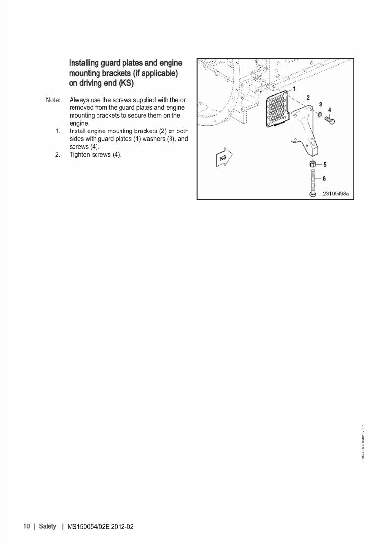
Installing guard plates and engine
mounting brackets (if applicable)
on driving end (KS)
Note: Always use the screws supplied with the or removed from the guard plates and enginemounting brackets to secure them on theengine.
1. Install engine mounting brackets (2) on bothsides with guard plates (1) washers (3), andscrews (4).
2. Tighten screws (4).
10 | Safety | MS150054/02E 2012-02
T I M - I D : 0 0 0 0 0 0 4 0 1 0 - 0 0 7
8/10/2019 MS150054_02E.pdf
http://slidepdf.com/reader/full/ms15005402epdf 11/155

8/10/2019 MS150054_02E.pdf
http://slidepdf.com/reader/full/ms15005402epdf 12/155
1.6 Explosion hazard when removing inspection port cover on
engine
DANGERExplosion hazard due to oil vapors.Risk of serious injury – danger to life
• Allow the engine to cool down before opening the crankcase!• Avoid open flames, electrical sparks and ignition sources.
Safety instructions
u Before starting maintenance work, allow the engine to cool down for at least 10 min. (danger of explosiondue to oil vapors).
12 | Safety | MS150054/02E 2012-02
T I M - I D : 0 0 0 0 0 2 2 9 3 1 - 0 0 6

8/10/2019 MS150054_02E.pdf
http://slidepdf.com/reader/full/ms15005402epdf 13/155
1.7 Safety regulations for maintenance and repair work
Safety regulations for maintenance and repair work
Have maintenance and repair work carried out by qualified and authorized personnel only.
Allow the engine to cool down before starting maintenance work (risk of explosion of oil vapors).
Before starting work, relieve pressure in systems and compressed-air lines which are to be opened.
Take special care when removing ventilation or plug screws from the engine. Cover the screw or plugwith a rag to prevent fluids escaping under pressure.
Take special care when draining hot fluids ⇒ Risk of injury.
When changing the engine oil or working on the fuel system, ensure that the engine room is adequatelyventilated.
Allow the engine / system to cool down before starting to work.
Observe the maintenance and repair instructions.
Never carry out maintenance and repair work with the engine running unless expressly instructed to doso.
Secure the engine against accidental starting.
Disconnect the battery when electrical starters are fitted.
Close the main valve on the compressed-air system and vent the compressed-air line when pneumaticstarters are fitted.
Disconnect the control equipment from the assembly or system.
Use only proper, calibrated tools. Observe the specified tightening torques during assembly/disassembly.
Carry out work only on assembles and/or units which are properly secured.
Never use lines for climbing.
Keep fuel injection lines and connections clean.
Always seal connections with caps or covers if a line is removed or opened.
Take care not to damage lines, in particular fuel lines, during maintenance and repair work.
Ensure that all retainers and dampers are installed correctly.
Ensure that all fuel injection and pressurized oil lines are installed with enough clearance to prevent con‐tact with other components. Do not place fuel or oil lines near hot components.
Do not touch elastomeric seals if they have carbonized or resinous appearance unless hands are proper‐ly protected.
Note cooling time for components which are heated for installation or removal ⇒ Risk of burning.
When working high on the engine, always use suitable ladders and work platforms. Make sure compo‐nents are placed on stable surfaces.
Observe special cleanness when conducting maintenance and repair work on the assembly or system.After completion of maintenance and repair work, make sure that no loose objects are in/on the assem‐bly or system.
Before barring the engine, make sure that nobody is standing in the danger zone. Check that all guardshave been reinstalled and that all tools and loose parts have been removed after working on the engine.
The following additional instructions apply to starters with beryllium copper pinion:• Breathing protection of filter class P2 must be applied during maintenance work to avoid health haz‐ards caused by the beryllium-containing pinion. Do not blow out the interior of the flywheel housing or the starter with compressed air. Clean the flywheel housing inside with a class H dust extraction de‐vice as an additional measure.
MS150054/02E 2012-02 | Safety | 13
T I M - I D : 0 0 0 0 0 0 0 8 7 9 - 0 2 2

8/10/2019 MS150054_02E.pdf
http://slidepdf.com/reader/full/ms15005402epdf 14/155

8/10/2019 MS150054_02E.pdf
http://slidepdf.com/reader/full/ms15005402epdf 15/155
For conducting light-beam procedures and measurement work, only the following laser devices must beused:• Laser devices of classes 1, 2 or 3A.• Laser devices of class 3B, which have maximum output in the visible wavelength range (400 to 700
nm), a maximum output of 5 mW, and in which the beam axis and surface are designed to preventany risk to the eyes.
MS150054/02E 2012-02 | Safety | 15
T I M - I D : 0 0 0 0 0 0 0 8 7 9 - 0 2 2
8/10/2019 MS150054_02E.pdf
http://slidepdf.com/reader/full/ms15005402epdf 16/155
1.8 Fluids and lubricants, fire prevention and environmental
protection
Fire prevention
Rectify any fuel or oil leaks immediately; even splashes of oil or fuel on hot components can cause fires -therefore always keep the engine in a clean condition. Do not leave cloths soaked with fluids and lubri‐cants lying on or near the assembly or unit. Do not store inflammable material near the assembly or unit.
Do not weld pipes and components carrying oil or fuel! Before welding, clean with a nonflammable fluid.
When starting the engine with an external power source, connect the ground lead last and remove it first.To avoid sparks in the vicinity of the battery, connect the ground lead from the external power source tothe ground lead of the engine or to the ground terminal of the starter.
Always keep suitable firefighting equipment (fire extinguishers) at hand and familiarize yourself with their
use.
Noise
Noise can lead to an increased risk of accident if acoustic signals, warning shouts or noises indicatingdanger are drowned.
Wear ear protectors in work areas with a sound pressure level in excess of 85 dB (A).
Environmental protection and disposal
Modification or removal of mechanical or electronic components or the installation of additional compo‐nents as well as the execution of calibration processes that might affect the emission characteristics of the engine are prohibited by emission regulations. Emission control units/systems may only be main‐
tained, exchanged or repaired if the components used for this purpose are approved by MTU or equiva‐lent components. Noncompliance with these guidelines might represent a violation of the Clean Air Actand involves the termination of the operating license by the emission authorities. MTU does not acceptany liability for violations of the emission regulations. MTU will provide assistance and advice if emission-relevant components are intended to be modified. The MTU Maintenance Schedules ensure the reliabili‐ty and performance of MTU engines and must be complied with over the entire life cycle of the engine.
Use only fuel of prescribed quality to comply with emission limit values.
Dispose of used fluids, lubricants and filters in accordance with local regulations.
Within the EU, batteries can be returned free of charge to MTU FN / MTU Onsite Energy where they aresubjected to proper recycling procedures.
Fluids and lubricants
Use only fluids and lubricants that have been tested and approved by MTU.
Keep fluids and lubricants in suitable, properly designated containers. When using fluids, lubricants andother chemical substances, follow the safety instructions that apply to the product. Take special carewhen using hot, chilled or caustic materials. When using flammable materials, avoid all sparks and donot smoke.
Used oil
Used oil contains harmful combustion residues.
Rub barrier cream into hands.
Wash hands after contact with used oil.
16 | Safety | MS150054/02E 2012-02
T I M - I D : 0 0 0 0 0 0 0 8 8 0 - 0 1 4
8/10/2019 MS150054_02E.pdf
http://slidepdf.com/reader/full/ms15005402epdf 17/155
Lead
• When working with lead or lead-containing compounds, avoid direct contact to the skin and do notinhale lead vapors.
• Adopt suitable measures to avoid the formation of lead dust.
• Switch on extraction system.• Wash hands after contact with lead or lead-containing substances.
Compressed air
Observe special safety precautions when working with compressed air:
• Pay special attention to the pressure level in the compressed air network and pressure vessel.• Assemblies and equipment to be connected must either be designed for this pressure, or, if the per‐
mitted pressure for the connecting elements is lower than the pressure required, a pressure reducingvalve and safety valve (set to permitted pressure) must form an intermediate connection.
• Hose couplings and connections must be securely attached.• Wear goggles when blowing off components or blowing away chips.
• Provide the snout of the air nozzle with a protective disk (e.g. rubber disk).• First shut off compressed air lines before compressed air equipment is disconnected from the supply
line, or before equipment or tool is to be replaced.• Unauthorized use of compressed air, e.g. forcing flammable liquids (danger class AI, AII and B) out of
containers, results in a risk of explosion.• Forcing compressed air into thin-walled containers (e.g. containers made of tin, plastic and glass) for
drying purposes or to check for leaks, results in a risk of bursting.• Carry out leak test in accordance with the specifications.
Painting
• When carrying out painting work outside the spray stands provided with fume extraction systems, en‐sure that the area is well ventilated. Make sure that neighboring work areas are not impaired.
• No open flames.• No smoking.• Observe fire prevention regulations.• Always wear a mask providing protection against paint and solvent vapors.
Liquid nitrogen
• Store liquid nitrogen only in small quantities and always in regulation containers without fixed covers.• Avoid body contact (eyes, hands).• Wear protective clothing, protective gloves, closed shoes and protective goggles / safety mask.• Make sure that working area is well ventilated.• Avoid all knocks and jars to the containers, fixtures or workpieces.
Acids and alkaline solutions
• When working with acids and alkalis, wear protective goggles or face mask, gloves and protectiveclothing.
• If such solutions are spilled onto clothing, remove the affected clothing immediately.• Rinse injured parts of the body thoroughly with clean water.• Rinse eyes immediately with eyedrops or clean tap water.
MS150054/02E 2012-02 | Safety | 17
T I M - I D : 0 0 0 0 0 0 0 8 8 0 - 0 1 4

8/10/2019 MS150054_02E.pdf
http://slidepdf.com/reader/full/ms15005402epdf 18/155
1.9 Conventions for safety instructions in the text
DANGER
In the event of immediate danger.Consequences: Death or serious injury
• Remedial action
WARNINGIn the event of potentially dangerous situations.Consequences: Death or serious injury
• Remedial action
CAUTIONIn the event of dangerous situations.
Consequences: Minor injury or material damage
• Remedial action
Note: This manual contains highlighted safety warnings in accordance with the US ANSI Z535 standard whichbegin with one of the signal words listed above depending on the severity of the hazard.
Safety instructions
1. Read and familiarize yourself with all safety notices before starting up or repairing the product.2. Pass on all safety instructions to your operating, maintenance, repair and transport personnel.
18 | Safety | MS150054/02E 2012-02
T I M - I D : 0 0 0 0 0 0 0 8 8 1 - 0 1 5
8/10/2019 MS150054_02E.pdf
http://slidepdf.com/reader/full/ms15005402epdf 19/155
2 General Information
2.1 Engine side and cylinder designations
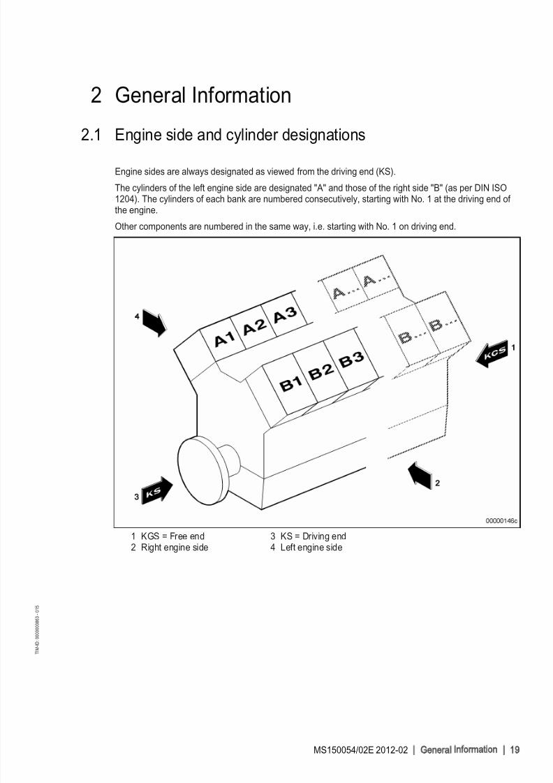
Engine sides are always designated as viewed from the driving end (KS).
The cylinders of the left engine side are designated "A" and those of the right side "B" (as per DIN ISO1204). The cylinders of each bank are numbered consecutively, starting with No. 1 at the driving end of the engine.
Other components are numbered in the same way, i.e. starting with No. 1 on driving end.
1 KGS = Free end
2 Right engine side
3 KS = Driving end
4 Left engine side
MS150054/02E 2012-02 | G eneral Information | 19
T I M - I D : 0 0 0 0 0 0 0 8 6 3 - 0 1 5

8/10/2019 MS150054_02E.pdf
http://slidepdf.com/reader/full/ms15005402epdf 20/155
2.2 Engine layout
Illustration also applicable to 16 V
1 Oil cooler 2 Crankcase breather 3 Exhaust pipe4 Combustion-air inlet con‐
nection (elbows are op‐tional)
5 Exhaust turbocharger 6 Exhaust gas outlet con‐
nection7 Engine governor
8 Intercooler 9 Flywheel
10 Lifting eye11 Starter 12 Charge-air pipe13 Engine mounting14 Oil filler neck15 Cylinder head16 Fuel priming pump17 Oil pan
18 Fuel filter 19 HP fuel pump20 Engine oil filter, (automat‐
ic oil filter is optional)21 Coolant filter 22 Centrifugal oil filter, (2
centrifugal oil filters areinstalled if automatic oilfilter is fitted)
Engine model designation
Key to the engine model designations 12/16 V 4000 Gxy
12/16 Number of cylinders
V Cylinder arrangement: V engine
4000 Series
G Application
x Application segment (7)
y Design index (3)
20 | G eneral Information | MS150054/02E 2012-02
T I M - I D : 0 0 0 0 0 0 9 9 7 5 - 0 0 2

8/10/2019 MS150054_02E.pdf
http://slidepdf.com/reader/full/ms15005402epdf 21/155
2.3 Sensors, actuators and injectors – Overview
Illustration also applicable to 16 V
a Version with easy-changefilter
b Version with automatic fil‐ter
1 Injectors Y39.1 to Y39.n(A-side)
2 B34 Fuel pressure after filter
3 F46 Leak fuel level moni‐toring
4 M8 Suction restrictor (HPpump)
5 F25 Differential engine oilpressure after filter
6 B05 Engine oil pressure
7 B07 Engine oil tempera‐ture
8 XY44 Solenoid valve of fan clutch
The injectors are underneath the cylinder head covers of the cylinder. Injector replacement and necessa‐
ry activities (→ Page 78).
MS150054/02E 2012-02 | G eneral Information | 21
T I M - I D : 0 0 0 0 0 1 2 9 1 8 - 0 0 2

8/10/2019 MS150054_02E.pdf
http://slidepdf.com/reader/full/ms15005402epdf 22/155
1 B50 Crankcase pressure2 B05 Engine oil pressure3 B33 Fuel temperature in
Common Rail4 B48 Fuel pressure in
Common Rail
5 B01 Camshaft speed6 B43 Charge-air coolant
pressure7 B26 Charge-air coolant
temperature
8 B06 Engine coolant tem‐perature
22 | G eneral Information | MS150054/02E 2012-02
T I M - I D : 0 0 0 0 0 1 2 9 1 8 - 0 0 2
8/10/2019 MS150054_02E.pdf
http://slidepdf.com/reader/full/ms15005402epdf 23/155
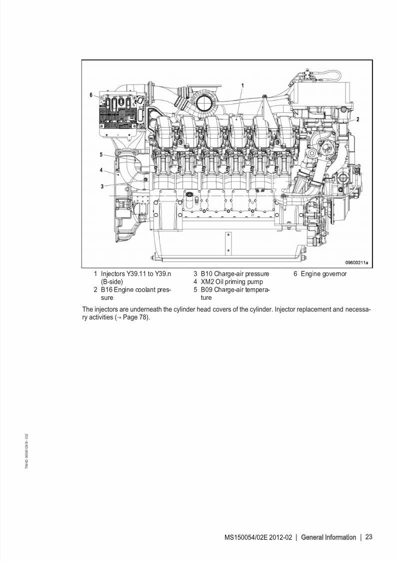
1 Injectors Y39.11 to Y39.n(B-side)
2 B16 Engine coolant pres‐sure
3 B10 Charge-air pressure4 XM2 Oil priming pump5 B09 Charge-air tempera‐
ture
6 Engine governor
The injectors are underneath the cylinder head covers of the cylinder. Injector replacement and necessa‐ry activities (→ Page 78).
MS150054/02E 2012-02 | G eneral Information | 23
T I M - I D : 0 0 0 0 0 1 2 9 1 8 - 0 0 2
8/10/2019 MS150054_02E.pdf
http://slidepdf.com/reader/full/ms15005402epdf 24/155
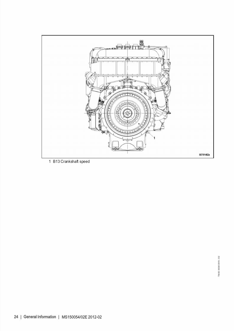
1 B13 Crankshaft speed
24 | G eneral Information | MS150054/02E 2012-02
T I M - I D : 0 0 0 0 0 1 2 9 1 8 - 0 0 2

8/10/2019 MS150054_02E.pdf
http://slidepdf.com/reader/full/ms15005402epdf 25/155
3 Technical Data
3.1 12, 16V 4000 G73 engine data, emissions-optimized (EPA -Tier 2)
Explanation
Abbr. Meaning
DL Ref. value: Continuous power
BL Ref. value: Fuel stop power
A Design value
G Guaranteed valueR Guideline value
L Limit value, up to which the engine can be operated without changes (e.g. of power set‐ting)
N Not yet defined value
- Not applicable
X Applicable
* Data not yet available when at time of publication
REFERENCE CONDITIONS
Engine model 12V 4000
G73
16 V4000
G73
Application group 3B 3B
Intake air temperature °C 25 25
Charge-air coolant temperature °C 45 45
Barometric pressure mbar 1000 1000
Site altitude above sea level m 100 100
POWER-RELATED DATA (power ratings are net brake power to ISO 3046)
Number of cylinders 12 16
Engine rated speed A rpm 1200 1200
Continuous power as per ISO 3046 (10% overload capability)(rated power DIN 6280, ISO 8528)
A kW 1105 1390
GENERAL CONDITIONS (for maximum power)
Number of cylinders 12 16
Intake air depression (new filter) A mbar 15 15
Intake air depression, max. L mbar 50 50
Exhaust backpressure A mbar 30 30
Exhaust back pressure, max. L mbar 50 50
MS150054/02E 2012-02 | Technical Data | 25
T I M - I D : 0 0 0 0 0 1 1 0 8 2 - 0 0 2

8/10/2019 MS150054_02E.pdf
http://slidepdf.com/reader/full/ms15005402epdf 26/155
MODEL-RELATED DATA (basic design)
Number of cylinders 12 16
Engine with turbochargers (ETC) and charge-air cooling (CAC) X X
Uncooled exhaust lines X X
Working method: four-stroke diesel engine, single-acting X X
Combustion method: direct injection X X
Cooling method: treated water X X
Direction of rotation: c.c.w. (viewed on driving end) X X
Number of cylinders 12 16
Cylinder configuration: V angle Degrees(°)
90 90
Bore mm 170 170
Stroke mm 210 210
Cylinder displacement liter 4.77 4.77
Total displacement liter 57.2 76.3
Compression ratio 16.4 16.4
Cylinder heads: Single cylinder heads X X
Cylinder liners: wet, replaceable X X
Number of inlet valves, per cylinder 2 2
Number of exhaust valves, per cylinder 2 2
Standard flywheel housing flange (engine main PTO) SAE 00 00
AIR / EXHAUST
Number of cylinders 12 16
Charge-air pressure before cylinder - DL R bar abs 3.3 3.0
COOLANT SYSTEM (HT circuit)
Number of cylinders 12 16
Coolant temperature (at engine connection: outlet to coolingequipment)
A °C 100 94
Coolant temperature after engine, warning R °C 102 102Coolant temperature after engine, shutdown L °C 104 105
Antifreeze percentage in coolant, max. L % 50 50
Pressure-loss in off-engine cooling system, max. L bar 0.7 0,7
COOLANT SYSTEM (LT circuit)
Number of cylinders 12 16
Coolant temperature before intercooler (at engine connection:inlet from cooling equipment)
A °C 45 45
Antifreeze percentage in coolant, max. L % 50 50
Pressure-loss in off-engine cooling system, max. L bar 0.7 0.7
26 | Technical Data | MS150054/02E 2012-02
T I M - I D : 0 0 0 0 0 1 1 0 8 2 - 0 0 2

8/10/2019 MS150054_02E.pdf
http://slidepdf.com/reader/full/ms15005402epdf 27/155
LUBE OIL SYSTEM
Number of cylinders 12 16
Lube oil operating temperature before engine, from R °C 88 84
Lube-oil operating temperature before engine, to R °C 98 94
Lube-oil temperature before engine, warning R °C 99 99
Lube-oil temperature before engine, shutdown L °C 101 101
Lube oil operating pressure before engine, from R bar 4 4.5
Lube oil operating pressure before engine, to R bar 6 6
FUEL SYSTEM
Number of cylinders 12 16
Fuel pressure at supply connection on engine, min. (when en‐
gine is starting)
L bar -0.1 -0.1
Fuel pressure at supply connection to engine (when engine isstarting), max.
L bar 1.5 1.5
GENERAL OPERATING DATA
Number of cylinders 12 16
Coolant preheating: preheating temperature (min.) R °C 40 40
Firing speed, from R rpm 80 80
Firing speed, to R rpm 120 120
CAPACITIES
Number of cylinders 12 16
Engine coolant, engine side (without cooling system) R liter 137 175
Charge-air coolant, engine side R liter 44 42
Engine oil capacity, initial filling (standard oil system) (Option:max. operating inclinations)
R liter 221 295
Oil pan capacity, dipstick mark min. (standard oil system) (Op‐tion: max. operating inclinations)
L liter 160 *
Oil pan capacity, dipstick mark max. (standard oil system) (Op‐
tion: max. operating inclinations)
L liter 210 260
WEIGHTS / MAIN DIMENSIONS
Number of cylinders 12 16
Engine dry weight (basic engine configuration acc. to specifiedscope of supply)
R kg 6300 7400
ACOUSTICS
Number of cylinders 12 16
Exhaust noise, unsilenced - DL (sound power level LW, ISO
6798)
R db(A) 125 124
Engine surface noise with attenuated intake noise (filter) - DL -(sound-power level LW, ISO 6798)
R db(A) 120 *
MS150054/02E 2012-02 | Technical Data | 27
T I M - I D : 0 0 0 0 0 1 1 0 8 2 - 0 0 2
8/10/2019 MS150054_02E.pdf
http://slidepdf.com/reader/full/ms15005402epdf 28/155
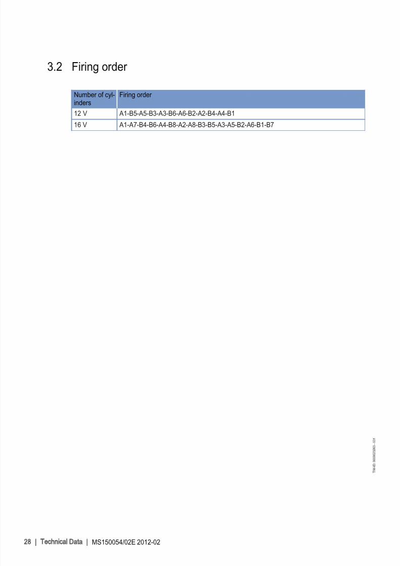
3.2 Firing order
Number of cyl‐inders
Firing order
12 V A1-B5-A5-B3-A3-B6-A6-B2-A2-B4-A4-B1
16 V A1-A7-B4-B6-A4-B8-A2-A8-B3-B5-A3-A5-B2-A6-B1-B7
28 | Technical Data | MS150054/02E 2012-02
T I M - I D : 0 0 0 0 0 2 3 2 6 3 - 0 0 1

8/10/2019 MS150054_02E.pdf
http://slidepdf.com/reader/full/ms15005402epdf 29/155

8/10/2019 MS150054_02E.pdf
http://slidepdf.com/reader/full/ms15005402epdf 30/155
4 Operation
4.1 Putting the engine into operation after extended out-of-service periods (>3 months)
Preconditions
☑ Engine is stopped and starting disabled.
☑ MTU Fluids and Lubricants Specifications (A001061/..) are available.
Putting into operation after long out-of-service periods (>3 months)
Item ActionEngine Depreserve (→ MTU Fluids and Lubricants Specifications A001061/..).
Valve drive Lubricate valve drive every ≥ 6 months (→ Page 72).
Lube oil system Check engine oil level (→ Page 102).
Bar engine with starting equipment (→ Page 64).
Fuel prefilter Fill with fuel (if fitted).
Coolant circuit If engine is out of service for more than one year, change engine coolant(→ Page 117).
Change charge-air coolant (→ Page 127).
Coolant circuit Check engine coolant level (→ Page 116);
Check charge-air coolant level (→ Page 126).
Coolant circuit Preheat coolant with coolant preheating unit (if applicable).
Engine governor Check plug connections (→ Page 143).
HP fuel pump Only for engines without oil priming pump
Fill HP fuel pump with new engine oil (→ Page 77).
30 | Operation | MS150054/02E 2012-02
T I M - I D : 0 0 0 0 0 0 2 2 0 0 - 0 0 4

8/10/2019 MS150054_02E.pdf
http://slidepdf.com/reader/full/ms15005402epdf 31/155
4.2 Putting the engine into operation after scheduled out-of-
service-period
Preconditions
☑ Engine is stopped and starting disabled.
Putting into operation
Item Action
Lube oil system Check engine oil level (→ Page 102).
Coolant circuit Check engine coolant level (→ Page 116), check charge-air coolant level(→ Page 126).
Coolant circuit Preheat engine coolant with coolant preheating unit, if fitted.
Fuel prefilter (if fitted) Drain water and contaminants, see manufacturer's documentation.
Engine control system Switch on.
MS150054/02E 2012-02 | Operation | 31
T I M - I D : 0 0 0 0 0 1 0 6 4 2 - 0 0 2

8/10/2019 MS150054_02E.pdf
http://slidepdf.com/reader/full/ms15005402epdf 32/155

8/10/2019 MS150054_02E.pdf
http://slidepdf.com/reader/full/ms15005402epdf 33/155

8/10/2019 MS150054_02E.pdf
http://slidepdf.com/reader/full/ms15005402epdf 34/155
4.5 Operational checks
DANGER
Unguarded rotating and moving engine components.Risk of serious injury – danger to life
• Take special care when working on a running engine.
WARNINGEngine noise above 85 dB (A).Risk of damage to hearing
• Wear ear protectors.
Operational checks
Item Task
Control and display panels Check readings of operational data (speed, temperature, pressures).
Engine oil Check engine oil level (→ Page 102).
Engine operation Check engine visually for leaks and general condition;
Check for abnormal running noise, exhaust discoloration and vibrations(→ Page 40).
Battery-charging generator Check battery-charging generator for contamination, clean as necessa‐ry (→ Page 134).
Air filter Check differential pressure indication at gauge (if fitted).
Exhaust system Check exhaust color (→ Page 40).
Fuel prefilter Drain water and contaminants at the drain cock of fuel prefilter (if fitted)(→ Page 88)
Check reading on vacuum gauge of fuel prefilter (if fitted).
Intercooler Check condensate drain(s) for water discharge and obstruction(→ Page 93).
Engine coolant pump Check relief bore (→ Page 123).
Charge-air coolant pump Check relief bore (→ Page 132).
34 | Operation | MS150054/02E 2012-02
T I M - I D : 0 0 0 0 0 2 8 4 1 3 - 0 0 2

8/10/2019 MS150054_02E.pdf
http://slidepdf.com/reader/full/ms15005402epdf 35/155
4.6 Stop engine in manual mode (testing mode)
Preconditions
☑ Generator (if provided) not connected to network.
☑ Engine is running in manual mode.
CAUTIONStopping the engine when it is running at full load causes extreme stress to the engine.Risk of overheating, damage to components
• Before stopping the engine, operate it at idle speed until operating temperatures decrease andstable values are indicated.
Preparing the generator drive (only with generator breaker)
Item Task
Engine After opening the generator breaker (if provided), allow to cool down off-load for approx. 5 minutes.
Preparing the pump drive (diesel-mechanical/diesel-electric)
Item Task
Engine Allow to cool down for approx. 5 minutes at reduced engine speed. Ob‐serve natural resonance of engine (installation-dependent)!
Stopping the engine
Item Task
Switchgear cabinet, controlpanel etc. (depending onmanufacturer)
Press stop button.
• Automatic stopping sequence is performed;• Engine is stopped.
After stopping the engine
Item Task
Coolant pump Allow to run on for sufficient time after stopping.
MS150054/02E 2012-02 | Operation | 35
T I M - I D : 0 0 0 0 0 0 2 2 8 5 - 0 0 1

8/10/2019 MS150054_02E.pdf
http://slidepdf.com/reader/full/ms15005402epdf 36/155

8/10/2019 MS150054_02E.pdf
http://slidepdf.com/reader/full/ms15005402epdf 37/155

8/10/2019 MS150054_02E.pdf
http://slidepdf.com/reader/full/ms15005402epdf 38/155
4.9 After stopping the engine – putting the engine out of service
Preconditions
☑ MTU Fluids and Lubricants Specifications (A001061/..) is available.
After stopping the engine
Item Task
Cooling system Drain engine coolant (→ Page 118);
Drain charge-air coolant (→ Page 128) if:• freezing temperatures are expected and the engine is to remain out of
service for an extended period and coolant has no antifreeze additive;• the engine room is not heated;• the coolant is not maintained at a suitable temperature;• the antifreeze concentration is insufficient for the engine-room tempera‐
ture;• antifreeze concentration is 50 % and engine-room temperature is below
-40°C.
Engine/generator/pumpcontroller
Switch OFF.
Air intake and exhaust sys‐tem
If the engine is to remain out of service for more than 1 week, seal theengine's air and exhaust sides. If the engine is to remain out of service for more than 1 month, preserve engine (→ MTU Fluids and Lubricants Speci‐fications A001061/.. ).
38 | Operation | MS150054/02E 2012-02
T I M - I D : 0 0 0 0 0 0 2 7 0 6 - 0 0 1

8/10/2019 MS150054_02E.pdf
http://slidepdf.com/reader/full/ms15005402epdf 39/155
5 Maintenance
5.1 Maintenance task reference table [QL1]The maintenance tasks and intervals for this product are defined in the Maintenance Schedule. TheMaintenance Schedule is a stand-alone publication.
The task numbers in this table provide reference to the maintenance tasks specified in the MaintenanceSchedule.
Task Maintenance tasks
W0500 Check engine oil level (→ Page 102)
W0501 Visually inspect engine for leaks and general condition (→ Page 34)
W0502 Check intercooler drain (if fitted) (→ Page 93)
W0503 Check air filter service indicator (→ Page 97)
W0505 Check relief bores of coolant pump(s) (→ Page 123)
W0506 Check engine for abnormal running noises, exhaust color and vibrations
(→ Page 34)
W0507 Drain water and contaminants from fuel prefilter (if fitted) (→ Page 34)
W0508 Check vacuum gauge reading on fuel prefilter (if fitted) (→ Page 34)
W0525 Check battery-charging generator for contamination, clean if necessary
(→ Page 134)
W1001 Replace fuel filter or fuel filter element (→ Page 85)
W1005 Replace air filter (→ Page 94)
W1006 Replace fuel injectors (→ Page 78)
W1008 Replace engine oil filter at each oil change or when the timelimit (years) is reached, at the latest
(→ Page 107)
W1009 Check layer thickness of oil residue, clean and replace filter sleeve (if fitted)
(→ Page 113)
W1011 Perform endoscopic inspection of combustion chambers (→ Page 66)
W1024 Check (electric) operation of emergency air-shutoff flaps (→ Page 98)
W1036 Replace coolant filter (→ Page 125)
W1046 Crankcase breather: Replace filter or filter element (→ Page 70)
W1241 Check condition of belt drive and replace if necessary; adjustbelt tension
(→ Page 133)
W1247 Lubricate emergency air-shutoff flap lubrication points
W1250 Replace all rubber sleeves (→ Page 96)
(→ Page 99)
W1251 Replace all hose lines
W1294 Check valve clearance, ATTENTION! Initial adjustment after 500 operating hours!
(→ Page 73)
Table 1: Maintenance task reference table [QL1]
MS150054/02E 2012-02 | Maintenance | 39
T I M - I D : 0 0 0 0 0 3 5 7 0 8 - 0 0 1

8/10/2019 MS150054_02E.pdf
http://slidepdf.com/reader/full/ms15005402epdf 40/155
6 Troubleshooting
6.1 Troubleshooting
Engine does not turn when starter is actuated
Component Cause Action
Battery Low or faulty Charge or replace (see manufacturer'sdocumentation).
Cable connections defective Check if cable connections are proper‐ly secured (see manufacturer's docu‐mentation).
Starter Engine wiring or starter defective Check if cable connections are proper‐ly secured, contact Service.
Engine cabling Faulty Check (→ Page 140).
Engine/generator control
Secure seating of assemblies or con‐nectors not provided
Perform visual inspection (see manu‐facturer's documentation).
Engine governor Plug-in connections are loose Check plug-in connections(→ Page 143).
Engine Running gear blocked (engine cannotbe barred manually).
Contact Service.
Engine turns but does not fire
Component Cause Action
Starter Poor rotation by starter: Battery low or defective.
Charge or replace battery (see manu‐facturer's documentation).
Engine cabling Faulty Check (→ Page 140).
Fuel system Air in fuel system. Vent fuel system (→ Page 84).
Engine governor Faulty Contact Service.
Engine fires unevenly
Component Cause Action
Fuel injection equip‐ment
Injector faulty. Replace (→ Page 78).
Engine cabling Faulty Check (→ Page 140).
Fuel system Air in fuel system. Vent fuel system (→ Page 84).
Engine governor Faulty Contact Service.
Engine does not reach rated speed
Component Cause Action
Fuel supply Fuel prefilter clogged. Replace
Easy-change fuel filter clogged Replace (→ Page 85).
Air supply Air filter clogged. Check signal ring position of service in‐dicator (if fitted) .
40 | Troubleshooting | MS150054/02E 2012-02
T I M - I D : 0 0 0 0 0 0 2 5 4 5 - 0 0 2

8/10/2019 MS150054_02E.pdf
http://slidepdf.com/reader/full/ms15005402epdf 41/155
Component Cause Action
Fuel injection equip‐ment
Injector faulty. Replace (→ Page 78).
Engine cabling Faulty Check (→ Page 140).
Engine Overload Contact Service.
Engine speed not steady
Component Cause Action
Fuel injection equip‐ment
Injector faulty. Replace (→ Page 78).
Speed sensor Faulty Contact Service.
Fuel system Air in fuel system. Vent fuel system (→ Page 84).
Engine governor Faulty Contact Service.
Charge air temperature too high
Component Cause Action
Engine coolant Incorrect engine coolant concentration. Check (MTU test kit).
Intercooler Contaminated Contact Service.
Engine room Air inlet temperature too high. Check fans and intake/exhaust lines.
Charge-air pressure too low
Component Cause Action
Air supply Air filter clogged. Check signal ring position of service in‐dicator (if fitted) .
Intercooler Contaminated Contact Service.
Exhaust turbocharger Faulty Contact Service.
Coolant leaks at intercooler
Component Cause Action
Intercooler Leaking, major coolant discharge. Contact Service.
Black exhaust gas
Component Cause Action
Air supply Air filter clogged. Check signal ring position of service in‐dicator (if fitted) .
Fuel injection equip‐ment
Injector faulty. Replace (→ Page 78).
Engine Overload Contact Service.
MS150054/02E 2012-02 | Troubleshooting | 41
T I M - I D : 0 0 0 0 0 0 2 5 4 5 - 0 0 2
8/10/2019 MS150054_02E.pdf
http://slidepdf.com/reader/full/ms15005402epdf 42/155
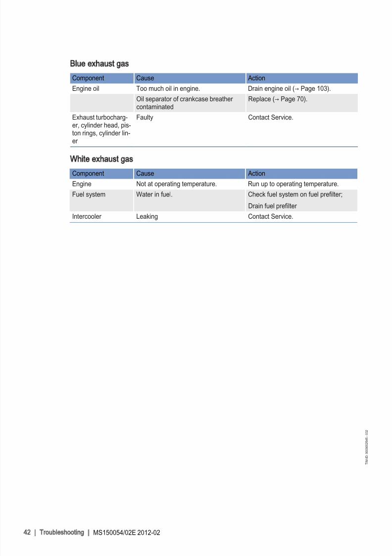
Blue exhaust gas
Component Cause Action
Engine oil Too much oil in engine. Drain engine oil (→ Page 103).
Oil separator of crankcase breather contaminated
Replace (→ Page 70).
Exhaust turbocharg‐er, cylinder head, pis‐ton rings, cylinder lin‐er
Faulty Contact Service.
White exhaust gas
Component Cause Action
Engine Not at operating temperature. Run up to operating temperature.
Fuel system Water in fuel. Check fuel system on fuel prefilter;
Drain fuel prefilter
Intercooler Leaking Contact Service.
42 | Troubleshooting | MS150054/02E 2012-02
T I M - I D : 0 0 0 0 0 0 2 5 4 5 - 0 0 2

8/10/2019 MS150054_02E.pdf
http://slidepdf.com/reader/full/ms15005402epdf 43/155
6.2 Engine governor ADEC (ECU 7) for Series 4000 Oil &Gas
engines – Fault messages
The fault code numbers are generated by the engine governor and transmitted to the display below.
The fault code (1) comprises three digits.
Fault messages may also be caused by faulty sensors/actuators. Contact Service to have sensors/actua‐
tors tested and replaced as necessary if troubleshooting as described in the table below proves unsuc‐cessful.
The table below lists possible fault codes:
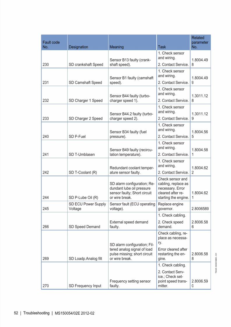
Fault codeNo. Designation Meaning Task
Relatedparameter No.
003 HI T-FuelPreliminary warning: Fueltemperature too high. Contact Service.
2.0122.931
004 SS T-Fuel
Main warning: Fuel temper‐ature too high; engine shut‐down. Contact Service.
2.0122.932
005 HI T-Charge Air
Preliminary warning:Charge-air temperature toohigh
1. Reduce power.
2. Check intercool‐er.
2.0121.931
006 SS T-Charge Air
Main warning: Charge-air temperature too high; en‐gine shutdown.
1. Reduce power.
2. Check intercool‐er.
2.0121.932
009HI T-Coolant Intercool‐er
Charge-air coolant tempera‐ture too high (1st limit val‐ue). Reduce power.
2.0124.931
010SS T-Coolant Intercool‐er
Main warning: Intercooler coolant temperature toohigh; engine shutdown. Reduce power.
2.0124.932
MS150054/02E 2012-02 | Troubleshooting | 43
T I M - I D : 0 0 0 0 0 1 6 8 6 5 - 0 0 1

8/10/2019 MS150054_02E.pdf
http://slidepdf.com/reader/full/ms15005402epdf 44/155
Fault codeNo. Designation Meaning Task
Relatedparameter No.
015 LO P-Lube OilOil pressure too low(1st limit value).
Check oil level, top
up as necessary(→ Page 102).
2.0100.921
016 SS P-Lube Oil
Oil pressure too low(2nd limit value), automaticengine shutdown.
1. Check oil level,top up as necessa‐ry (→ Page 102).
2. Attempt to re‐start engine(→ Page 32).
2.0100.922
019 HI T-Exhaust A
Exhaust temperature of cyl‐inder bank A too high(1st limit value).
1. Check cabling(→ Page 140).
2. Contact Service.2.0126.931
020 SS T-Exhaust A
Exhaust temperature of cyl‐inder bank A too high(2nd limit value).
1. Check cabling(→ Page 140).
2. Contact Service.2.0126.932
021 HI T-Exhaust B
Exhaust temperature of cyl‐inder bank B too high(1st limit value).
1. Check cabling(→ Page 140).
2. Contact Service.2.0127.931
022 SS T-Exhaust B
Exhaust temperature of cyl‐inder bank B too high(2nd limit value).
1. Check cabling(→ Page 140).
2. Contact Service.2.0127.932
023 LO Coolant LevelCoolant level too low(1st limit value).
Check coolant lev‐el in expansiontank (→ Page 116).
2.0152.921
024 SS Coolant LevelCoolant level too low(2nd limit value).
Check coolant lev‐el in expansiontank (→ Page 116).
2.0152.912
025 HI P-Diff-Lube OilOil filter differential pressuretoo high (1st limit value).
Replace oil filter candles(→ Page 108).
2.0154.931
026 SS P-Diff-Lube Oil
Alarm configuration limitvalue 1; Preliminary warn‐
ing: Oil filter differentialpressure too high.
Replace oil filter
candles(→ Page 108).
2.0154.932
027 HI Level Leakage FuelLeak fuel level too high (1stlimit value).
1. Check fuel sys‐tem.
2. Contact Service.2.0151.931
029HI ETC Idle Speed tooHigh
Idle speed of ETC 2 toohigh. Contact Service.
1.8004.206
030 SS Engine Overspeed
Engine overspeed; auto‐
matic engine shutdown.
1. Acknowledgealarm.
2. Attempt to re‐
start engine.
2.2510.93
2
44 | Troubleshooting | MS150054/02E 2012-02
T I M - I D : 0 0 0 0 0 1 6 8 6 5 - 0 0 1

8/10/2019 MS150054_02E.pdf
http://slidepdf.com/reader/full/ms15005402epdf 45/155
Fault codeNo. Designation Meaning Task
Relatedparameter No.
031 HI ETC1 Overspeed
Alarm configuration limit
value 1; preliminary warn‐ing: speed of primary turbo‐charger too high. Contact Service.
2.3011.931
032 SS ETC1 OverspeedETC 1 – overspeed (2ndlimit value)
Automatic power reduction by en‐gine control sys‐tem. Check air fil‐ters.
2.3012.932
036 HI ETC2 Overspeed
Alarm configuration limitvalue 1; preliminary warn‐ing: speed of secondary tur‐
bocharger too high.
1. Reduce power.
2. Contact Service.
2.3013.93
1
037 SS ETC2 Overspeed
Alarm configuration limitvalue 2; main warning:speed of secondary turbo‐charger too high. Fuel limi‐tation to a fixed value.
1. Reduce power.
2. Contact Service.2.3013.912
038AL ETC Speed Devia‐tion
Synchronization error be‐tween ETCs 1 and 2.
1. Reduce power.
2. Contact Service.1.8004.205
039 AL ETC2 Cutin Failure ETC2 failed to cut in.
1. Reduce power.
2. Contact Service.1.8004.204
044 L1 Coolant Level Inter‐cooler Charge-air coolant level toohigh/low (1st limit). Check coolant lev‐el (→ Page 126). 2.0153.921
051 HI T-Lube OilLube oil temperature toohigh (1st limit). Reduce power.
2.0125.931
052 SS T-Lube OilLube oil temperature toohigh (2nd limit).
1. Reduce power.
2. Check engine oillevel(→ Page 102).
2.0125.932
057 LO P-CoolantCoolant pressure too low(1st limit).
Check coolant cir‐cuit.
2.0101.921
058 SS P-CoolantCoolant pressure too low(2nd limit).
Automatic engineshutdown. Checkcoolant level(→ Page 116).
2.0101.922
063 HI P-Crank CasePreliminary warning: Crank‐case pressure too high.
1. Reduce power.
2. Replace filter el‐ement of oil sepa‐rator (→ Page 70).
2.0106.931
064 SS P-Crank Case
Main warning: Crankcasepressure too high; engine
shutdown.
1. Contact Service.
2. Replace filter el‐ement of oil sepa‐
rator (→ Page 70).
2.0106.93
2
MS150054/02E 2012-02 | Troubleshooting | 45
T I M - I D : 0 0 0 0 0 1 6 8 6 5 - 0 0 1
8/10/2019 MS150054_02E.pdf
http://slidepdf.com/reader/full/ms15005402epdf 46/155

8/10/2019 MS150054_02E.pdf
http://slidepdf.com/reader/full/ms15005402epdf 47/155
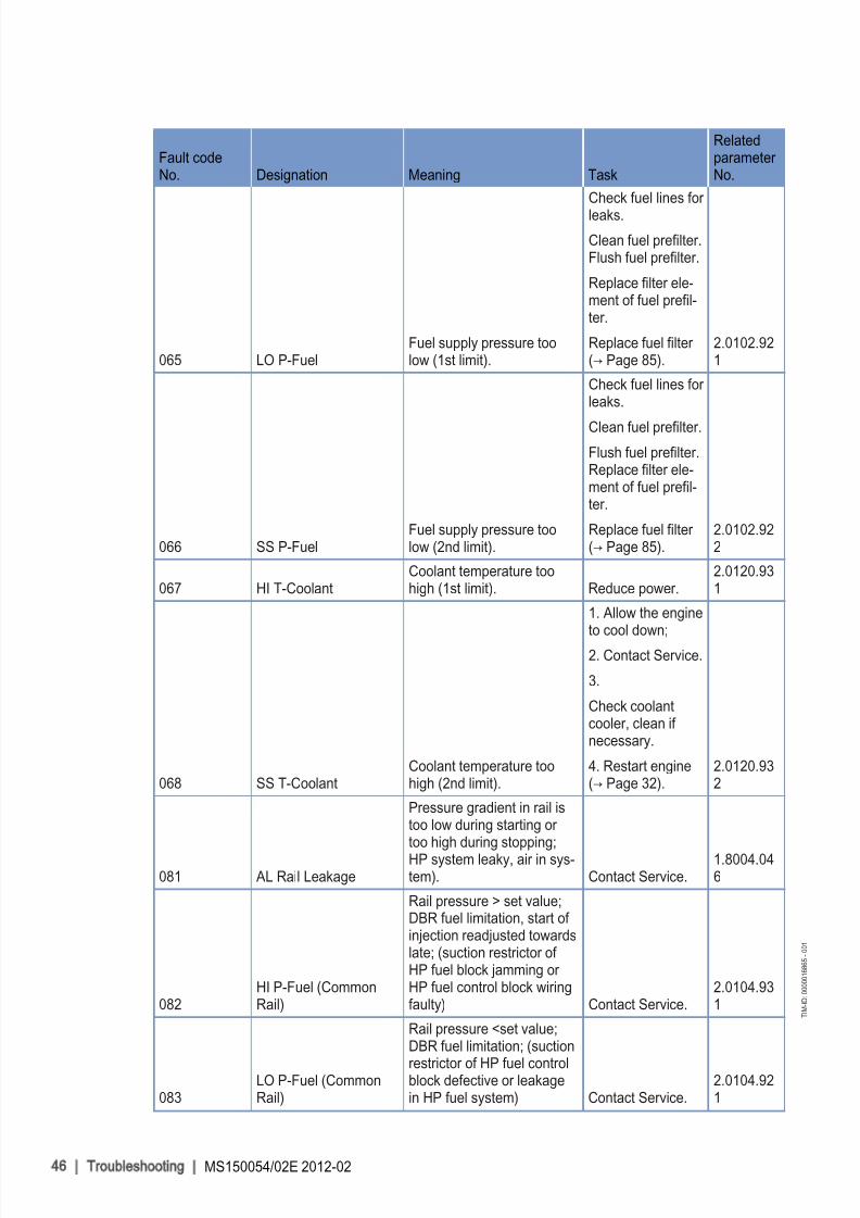
Fault codeNo. Designation Meaning Task
Relatedparameter No.
085 HI T-Recirculation
Preliminary warning: Recir‐
culation temperature toohigh. Reduce power.
2.0128.931
086 SS T-RecirculationMain warning: Recirculationtemperature too high. Reduce power.
2.0128.932
089SS Engine Speed tooLow
Engine speed did not attain200 rpm. A stop is activat‐ed.
Check for addition‐al messages.
2.2500.030
090SS Idle Speed NotReached
Alarm configuration limitvalue; Idling speed was notattained. Contact Service.
2.1090.925
091SS Release Speed NotReached
Alarm configuration limitvalue; Runup speed wasnot attained. Contact Service.
2.1090.924
092SS Starter Speed NotReached
Alarm configuration limitvalue; Starter speed wasnot attained; Termination of starting sequence; Starter rotates too slowly or doesnot rotate at all. Contact Service.
2.1090.923
093 SS T-Preheat
Alarm configuration limitvalue 2; Main warning: pre‐heating temperature too
low; coolant temperaturetoo low for engine start; en‐gine start interlock active. Check preheater.
2.1090.922
094 LO T-Preheat
Alarm configuration limitvalue 1; Preheating temper‐ature too low; coolant tem‐perature too low for enginestart. Check preheater.
2.1090.921
095 AL Prelubrication FaultAlarm configuration; Oil pri‐ming fault.
Check oil primingsystem.
2.1090.920
102AL Cons. Counter De‐fect
Invalid fuel consumption
display, checksum error inEDM/EEPROM 1 (redun‐dant data record 1). Contact Service.
1.8004.624
104AL Eng Hours Counter Defect
Checksum error of hour me‐ter in EDM/EEPROM 1 . Contact Service. 18004.623
118LO ECU Power SupplyVoltage
Supply voltage too low (1stlimit value).
Check ECU supplyvoltage.
Contact Service.2.0140.921
119LOLO Power ECUSupply Voltage
Supply voltage too low (2ndlimit value).
Check ECU supplyvoltage.
Contact Service.2.0140.922
120HI ECU Power SupplyVoltage
Supply voltage too high (1stlimit value).
Check ECU supplyvoltage.
Contact Service.2.0140.931
MS150054/02E 2012-02 | Troubleshooting | 47
T I M - I D : 0 0 0 0 0 1 6 8 6 5 - 0 0 1

8/10/2019 MS150054_02E.pdf
http://slidepdf.com/reader/full/ms15005402epdf 48/155
Fault codeNo. Designation Meaning Task
Relatedparameter No.
121HIHI ECU Power Sup‐ply Voltage
Supply voltage too high
(2nd limit value); automaticengine shutdown (configu‐rable).
Check ECU supplyvoltage.
Contact Service.2.0140.932
122 HI T-ECUTemperature in ECU hous‐ing too high (1st limit value).
1. Improve engineroom ventilation.
2. Reduce power.2.0132.921
13415V POS ECU DE‐FECT
Internal voltage (-15 VDC)faulty; automatic engineshutdown.
Replace enginegovernor.
13615V NEG ECU DE‐FECT
Internal voltage (-15 VDC)missing; automatic engineshutdown. Contact Service.
139 L1 TE BUFFER TESTSupply voltage of tempera‐ture sensors faulty.
Contact Service.Check sensors;Replace enginegovernor.
140 TE BUF. ECU DEFECTSupply voltage of tempera‐ture sensors faulty.
Contact Service.Check sensors;Replace enginegovernor.
142 BANK1 ECU DEFECT
Power output stage for con‐trol of the solenoid valves
on bank 1 is faulty; Enginedoes not start.
Replace enginegovernor.
144 BANK2 ECU DEFECT
Power output stage for con‐trol of the solenoid valveson bank 2 is faulty; Enginedoes not start.
Replace enginegovernor.
14515V_GOOD ECU DE‐FECT
Power supply faulty; auto‐matic engine shutdown.
Replace enginegovernor.
146 L1 AD-TEST1 SUPPLYSupply voltage A/D convert‐er too low.
Replace enginegovernor.
147 AD-TEST1 ECU DE‐FECT Electronic fault; automaticengine shutdown. Replace enginegovernor.
148 L1 AD-TEST2 SUPPLYSupply voltage A/D convert‐er too low.
Replace enginegovernor.
149AD-TEST2 ECU DE‐FECT
Internal electronic fault; au‐tomatic engine shutdown.
Replace enginegovernor.
150 L1 AD-TEST3 SUPPLYInternal electronic fault; au‐tomatic engine shutdown.
Replace enginegovernor.
151AD-TEST3 ECU DE‐FECT
Internal electronic fault; au‐tomatic engine shutdown.
Replace enginegovernor.
176AL LifeData not availa‐ble
Alarm configuration; No (ap‐
propriate) LifeData backupsystem available, ECU re‐set after expiration of time-out period. Contact Service.
2.4000.004
48 | Troubleshooting | MS150054/02E 2012-02
T I M - I D : 0 0 0 0 0 1 6 8 6 5 - 0 0 1
8/10/2019 MS150054_02E.pdf
http://slidepdf.com/reader/full/ms15005402epdf 49/155
Fault codeNo. Designation Meaning Task
Relatedparameter No.
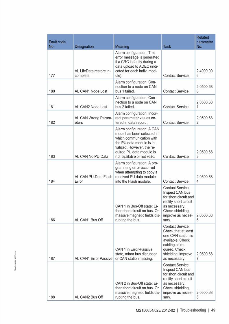
177AL LifeData restore in‐complete
Alarm configuration; This
error message is generatedif a CRC is faulty during adata upload to ADEC (indi‐cated for each indiv. mod‐ule). Contact Service.
2.4000.006
180 AL CAN1 Node Lost
Alarm configuration; Con‐nection to a node on CANbus 1 failed. Contact Service.
2.0500.680
181 AL CAN2 Node Lost
Alarm configuration; Con‐nection to a node on CANbus 2 failed. Contact Service.
2.0500.681
182AL CAN Wrong Param‐eters
Alarm configuration; Incor‐rect parameter values en‐tered in data record. Contact Service.
2.0500.682
183 AL CAN No PU-Data
Alarm configuration; A CANmode has been selected inwhich communication withthe PU data module is ini‐tialized. However, the re‐quired PU data module isnot available or not valid. Contact Service.
2.0500.683
184AL CAN PU-Data FlashError
Alarm configuration; A pro‐gramming error occurredwhen attempting to copy areceived PU data moduleinto the Flash module. Contact Service.
2.0500.684
186 AL CAN1 Bus Off
CAN 1 in Bus-Off state: Ei‐ther short circuit on bus. Or massive magnetic fields dis‐rupting the bus.
Contact Service.Inspect CAN busfor short circuit andrectify short circuitas necessary.Check shielding,improve as neces‐sary.
2.0500.686
187 AL CAN1 Error Passive
CAN 1 in Error-Passivestate, minor bus disruptionor CAN station missing.
Contact Service.Check that at leastone CAN station isavailable. Checkcabling as re‐quired. Checkshielding, improveas necessary.
2.0500.687
188 AL CAN2 Bus Off
CAN 2 in Bus-Off state: Ei‐ther short circuit on bus. Or massive magnetic fields dis‐rupting the bus.
Contact Service.Inspect CAN busfor short circuit andrectify short circuit
as necessary.Check shielding,improve as neces‐sary.
2.0500.688
MS150054/02E 2012-02 | Troubleshooting | 49
T I M - I D : 0 0 0 0 0 1 6 8 6 5 - 0 0 1

8/10/2019 MS150054_02E.pdf
http://slidepdf.com/reader/full/ms15005402epdf 50/155

8/10/2019 MS150054_02E.pdf
http://slidepdf.com/reader/full/ms15005402epdf 51/155
Fault codeNo. Designation Meaning Task
Relatedparameter No.
214 SD P-CrankCaseSensor B50 faulty (crank‐case pressure).
1. Check cabling.
2. Replace if nec‐essary.
1.8004.568
215 SD P-HD
Sensor B48 faulty (rail pres‐sure, HP regulator); emer‐gency mode active.
1. Check cabling.
2. Replace if nec‐essary.
1.8004.567
216 SD T-Lube OilSensor B07 faulty (lube oiltemperature).
1. Check cabling.
2. Replace if nec‐essary.
1.8004.575
219 SD T-Intake Air Sensor B03 faulty (intakeair temperature).
1. Check cabling.
2. Replace if nec‐essary.
1.8004.573
220SD Level Coolant Wa‐ter
Sensor F33 faulty (coolantlevel 1).
1. Switch systemOFF and ONagain;
2. Check error message;
3. Check cabling;
4. Contact Service;
5. Check sensor.1.8004.584
221 SD Diff-Lube OilSensor F25 faulty (lube oildifferential pressure).
1. Check sensor and wiring.
2. Replace if nec‐essary.
Error cleared after restarting the en‐gine.
1.8004.585
222 SD Level Leakage FuelSensor F46 faulty (leakfuel).
1. Check sensor and wiring.
2. Replace if nec‐
essary.3. Contact Service.
1.8004.582
223SD Level Coolant Inter‐cooler
Sensor F57 faulty (charge-air coolant level).
1. Check sensor and wiring.
2. Contact Service.1.8004.583
227 SD P-Oil before Filter
SD alarm configuration;Sensor B5.3 (lube oil pres‐sure before filter) faulty;short circuit or wire break.
Check sensor andcabling, replace asnecessary. Error cleared after re‐starting the engine.
1.8004.620
229AL Stop Camshaft Sen‐sor Defect
Crankshaft and camshaftspeed sensor faulty.
1. Check cabling.
2. Contact Serv‐ice.; Check sensor.
1.8004.562
MS150054/02E 2012-02 | Troubleshooting | 51
T I M - I D : 0 0 0 0 0 1 6 8 6 5 - 0 0 1
8/10/2019 MS150054_02E.pdf
http://slidepdf.com/reader/full/ms15005402epdf 52/155

8/10/2019 MS150054_02E.pdf
http://slidepdf.com/reader/full/ms15005402epdf 53/155
Fault codeNo. Designation Meaning Task
Relatedparameter No.
301AL Timing Cylinder (A1-A10)
Timing Bank 1 (solenoidvalve 1) ... Timing Bank 1(solenoid valve 10)
Replace injector
concerned if thefault message ap‐pears frequently(→ Page 78).
1.8004.500
3021.8004.501
3031.8004.502
3041.8004.503
3051.8004.504
3061.8004.505
3071.8004.506
3081.8004.507
3091.8004.508
310
1.8004.50
9
311AL Timing Cylinder (B1- B10)
Timing Bank 2 (solenoidvalve 1) ... Timing Bank 2(solenoid valve 10)
Replace injector concerned if thefault message ap‐pears frequently(→ Page 78).
1.8004.510
3121.8004.511
3131.8004.512
3141.8004.513
3151.8004.514
3161.8004.515
3171.8004.516
3181.8004.517
319
1.8004.51
8
3201.8004.519
MS150054/02E 2012-02 | Troubleshooting | 53
T I M - I D : 0 0 0 0 0 1 6 8 6 5 - 0 0 1

8/10/2019 MS150054_02E.pdf
http://slidepdf.com/reader/full/ms15005402epdf 54/155
Fault codeNo. Designation Meaning Task
Relatedparameter No.
321AL Wiring Cylinder (A1-A10)
Wiring Bank 1 (solenoidvalve 1) ... Wiring Bank 1(solenoid valve 10)
1. Check solenoid
valve.
2. Contact Service.1.8004.520
3221.8004.521
3231.8004.522
3241.8004.523
3251.8004.524
3261.8004.525
3271.8004.526
3281.8004.527
3291.8004.528
3301.8004.529
331AL Wiring Cylinder (B1-B10)
Wiring Bank 2 (solenoidvalve 1) ... Wiring Bank 2(solenoid valve 10)
1. Check solenoidvalve.
2. Contact Service.1.8004.530
3321.8004.531
3331.8004.532
3341.8004.533
335
1.8004.53
4
3361.8004.535
3371.8004.536
3381.8004.537
3391.8004.538
3401.8004.539
341AL Open Load Cylinder (A1- A10)
Open Load Bank 1 (sole‐noid valve 1) ... Open LoadBank 1 (solenoid valve 10)
1. Check solenoidvalve.
2. Contact Service.1.8004.540
54 | Troubleshooting | MS150054/02E 2012-02
T I M - I D : 0 0 0 0 0 1 6 8 6 5 - 0 0 1

8/10/2019 MS150054_02E.pdf
http://slidepdf.com/reader/full/ms15005402epdf 55/155

8/10/2019 MS150054_02E.pdf
http://slidepdf.com/reader/full/ms15005402epdf 56/155
Fault codeNo. Designation Meaning Task
Relatedparameter No.
362 AL Power Stage High
Alarm configuration; Internal
electronic fault (electronicspossibly faulty: Start ITS). If the ITS diagnosis result is"electronics OK", note fur‐ther fault messages (e.g.cabling faults).
1. Check solenoidvalve cabling.
2. Replace enginegovernor.
1.8004.497
363 AL Stop Power Stage
Alarm configuration; Internalelectronic fault (electronicspossibly faulty: Start ITS).
1. Check cabling.
2. Attempt to re‐start engine.
1.8004.560
365AL Stop MV-WiringGround
Alarm configuration; Injector cabling fault. If bit
"1.1020.021" (Power StageFailure: Stop Engine) is set,engine will be shut down asadditional measure. 1. Shortcircuit of positive connectionof one or more injectors toground 2. Short circuit of negative connection of oneor more injectors to ground .
1. Check cabling.
2. Attempt to re‐start engine.
1.8004.561
371 AL Wiring TO 1
Alarm configuration; Shortcircuit or wire break on tran‐sistor output 1 (TO 1).
1. Check turbo‐charger valve/ca‐bling, repair as
necessary
2. Replace enginegovernor.
1.8004.634
372 AL Wiring TO 2
Alarm configuration; Shortcircuit or wire break on tran‐sistor output 2 (TO 2).
1. Check recircula‐tion valve/cabling,repair as necessa‐ry
2. Replace enginegovernor.
1.8004.635
373 AL Wiring TO 3
Alarm configuration; Shortcircuit or wire break on tran‐sistor output 3 (TO 3). -
1.8004.636
374 AL Wiring TO 4
Alarm configuration; Shortcircuit or wire break on tran‐sistor output 4 (TO 4). -
1.8004.637
381 AL Wiring TOP 1
Alarm configuration; Shortcircuit or wire break on tran‐sistor output, plant-side 1(TOP 1).
Check cabling toplant.
2.8006.638
382 AL Wiring TOP 2
Alarm configuration; Shortcircuit or wire break on tran‐sistor output, plant-side 2
(TOP 2).
Check cabling to
plant.
2.8006.63
9
56 | Troubleshooting | MS150054/02E 2012-02
T I M - I D : 0 0 0 0 0 1 6 8 6 5 - 0 0 1

8/10/2019 MS150054_02E.pdf
http://slidepdf.com/reader/full/ms15005402epdf 57/155
Fault codeNo. Designation Meaning Task
Relatedparameter No.
383 AL Wiring TOP 3
Alarm configuration; Short
circuit or wire break on tran‐sistor output, plant-side 3(TOP 3).
Check cabling toplant.
2.8006.640
384 AL Wiring TOP 4
Alarm configuration; Shortcircuit or wire break on tran‐sistor output, plant-side 4(TOP 4).
Check cabling toplant.
2.8006.641
390 AL MCR exceeded
Alarm configuration; DBR/
MCR function: MCR hasbeen exceeded.
1. If alarm is onlytemporary, no ac‐tion required;
2. <if alarm is con‐
tinuously active,contact Service.
1.1085.009
392 HI T-Coolant Red
Alarm configuration limitvalue 1; Preliminary warn‐ing: Redundant coolanttemperature reading toohigh.
1. Check cabling.
2. Contact Service.2.0129.931
393 SS T-Coolant Red
Alarm configuration limitvalue 1; Main warning: Re‐dundant coolant tempera‐ture reading too high; en‐gine shutdown.
1. Check sensor and wiring.
2. Contact Service.2.0129.932
394 LO P-Lube Oil Red
Alarm configuration limitvalue 1; Preliminary warn‐ing: Redundant lube oilpressure reading too low.
1. Check sensor and wiring.
2. Contact Service.2.0112.921
395 SS P-Lube Oil Red
Alarm configuration limitvalue 2; Main warning: Re‐dundant lube oil pressurereading too low.
1. Check sensor and wiring.
2. Contact Service.2.0112.922
396
AL T-Coolant Max De‐
viation
Alarm configuration; Maxi‐mum coolant temperature
deviation.
1. Check sensor and wiring.
2. Contact Service.
1.8004.62
6
397 AL P-Oil Max Deviation
Alarm configuration; Maxi‐mum lube oil pressure devi‐ation.
1. Check sensor and wiring.
2. Contact Service.1.8004.625
400AL Open Load DigitalInput 1
Alarm configuration; Linedisruption on digital input 1;Cabling faulty or no resist‐ance over switch.
1. Check cabling.
2. Contact Serv‐ice.;
3. Check input of target device.
2.8006.625
401AL Open Load DigitalInput 2
Alarm configuration; Linedisruption on digital input 2;Cabling faulty or no resist‐ance over switch.
1. Check cabling.
2. Contact Serv‐ice.; Check input of target device.
2.8006.626
MS150054/02E 2012-02 | Troubleshooting | 57
T I M - I D : 0 0 0 0 0 1 6 8 6 5 - 0 0 1

8/10/2019 MS150054_02E.pdf
http://slidepdf.com/reader/full/ms15005402epdf 58/155
Fault codeNo. Designation Meaning Task
Relatedparameter No.
402AL Open Load DigitalInput 3
Alarm configuration; Linedisruption on digital input 3;Cabling faulty or no resist‐ance over switch.
1. Check cabling.
2. Contact Serv‐ice.; Check input of target device.
2.8006.627
403AL Open Load DigitalInput 4
Alarm configuration; Linedisruption on digital input 4;Cabling faulty or no resist‐ance over switch.
1. Check cabling.
2. Contact Serv‐ice.; Check input of target device.
2.8006.628
404
AL Open Load Digital
Input 5
Alarm configuration; Linedisruption on digital input 5;Cabling faulty or no resist‐
ance over switch.
1. Check cabling.
2. Contact Serv‐ice.; Check input of
target device.
2.8006.62
9
405AL Open Load DigitalInput 6
Alarm configuration; Linedisruption on digital input 6;Cabling faulty or no resist‐ance over switch.
1. Check cabling.
2. Contact Serv‐ice.; Check input of target device.
2.8006.630
406AL Open Load DigitalInput 7
Alarm configuration; Linedisruption on digital input 7;Cabling faulty or no resist‐ance over switch.
1. Check cabling.
2. Contact Serv‐ice.; Check input of target device.
2.8006.631
407AL Open Load DigitalInput 8
Alarm configuration; Line
disruption on digital input 8;Cabling faulty or no resist‐ance over switch.
1. Check cabling.
2. Contact Serv‐ice.; Check input of target device.
2.8006.632
408AL Open Load Emerg.Stop Input ESI
Alarm configuration; Linedisruption on the input for emergency stop; Cablingfaulty or no resistance over switch.
1. Check cabling.
2. Contact Serv‐ice.; Check input of target device.
2.8006.633
410 LO U-PDU
Alarm configuration limit
value 1; Preliminary warn‐ing: Injector voltage too low.
1. Check cabling.
2. Check power supply.
3. Contact Service. 2.0141.921
411 LOLO U-PDU
Alarm configuration limitvalue 2; Main warning: In‐
jector voltage too low.
1. Check cabling.
2. Check power supply.
3. Contact Service.2.0141.922
412 HI U-PDU
Alarm configuration limitvalue 1; Preliminary warn‐ing: Injector voltage toohigh.
1. Check cabling.
2. Check power supply.
3. Contact Service.2.0141.931
58 | Troubleshooting | MS150054/02E 2012-02
T I M - I D : 0 0 0 0 0 1 6 8 6 5 - 0 0 1

8/10/2019 MS150054_02E.pdf
http://slidepdf.com/reader/full/ms15005402epdf 59/155
Fault codeNo. Designation Meaning Task
Relatedparameter No.
413 HIHI U-PDU
Alarm configuration limitvalue; Main warning: Injec‐tor voltage too high.
1. Check cabling.
2. Check power supply.
3. Contact Service.2.0141.932
414HI Level Water FuelPrefilter
Alarm configuration limitvalue 1; Warning: water lev‐el in fuel prefilter too high. Drain water.
2.0156.931
415LO P-Coolant Intercool‐er
Alarm configuration limitvalue 1; Preliminary warn‐ing: Coolant pressure in in‐tercooler too low.
Top up coolant(→ Page 129).
2.0107.921
416SS P-Coolant Intercool‐er
Alarm configuration limitvalue 2; Main warning:Coolant pressure in inter‐cooler too low. engine shut‐down.
Top up coolant(→ Page 129).
2.0107.922
417SD Level Water FuelPrefilter
SD alarm configuration;Sensor for water level infuel prefilter faulty; short cir‐cuit or wire break.
Check sensor andcabling, replace asnecessary. Error cleared after re‐starting the engine.
1.8004.594
420 L1 Aux 1
Alarm configuration limitvalue 1; Input signal of Aux1 has exceeded/not at‐tained limit value 1, depend‐ing on configuration.
Determine andrectify reason for limit value viola‐tion.
2.0160.921
421 L2 Aux 1
Alarm configuration limitvalue 1; Input signal of Aux1 has exceeded/not at‐tained limit value 2, depend‐ing on configuration.
Determine andrectify reason for limit value viola‐tion.
2.0160.922
428 L1 T-Aux 1
Alarm configuration limitvalue 1; Preliminary warn‐ing: Temperature signal of
Aux 1 has exceeded / notattained limit value 1, de‐pending on configuration.
Determine and
rectify reason for limit value viola‐tion.
2.0130.921
440 L1 P-Aux 1
Alarm configuration limitvalue 1; Preliminary warn‐ing: Pressure signal of Aux1 has exceeded / not at‐tained limit value 1, depend‐ing on configuration.
Determine andrectify reason for limit value viola‐tion.
2.0110.921
442 L2 P-Aux 1
Alarm configuration limitvalue 2; Preliminary warn‐ing: Pressure signal of Aux
1 has exceeded / not at‐tained limit value 2, depend‐ing on configuration.
Determine and
rectify reason for limit value viola‐tion.
2.0110.931
MS150054/02E 2012-02 | Troubleshooting | 59
T I M - I D : 0 0 0 0 0 1 6 8 6 5 - 0 0 1

8/10/2019 MS150054_02E.pdf
http://slidepdf.com/reader/full/ms15005402epdf 60/155
Fault codeNo. Designation Meaning Task
Relatedparameter No.
444 SD U-PDU
SD alarm configuration; In‐
jector power stage sensor defect; Internal fault inECU7.
Replace ADEC(ECU 7).
1.8004.578
445 SD P-Ambient Air
SD alarm configuration;Ambient air pressure sensor faulty.
Replace enginegovernor.
1.8004.580
448 HI P-Charge Air
Alarm configuration limitvalue 1; Preliminary warn‐ing: Charge-air pressure toohigh. Contact Service.
2.0103.931
449 SS P-Charge Air
Alarm configuration limit
value 2; Main warning:Charge-air pressure toohigh. Contact Service.
2.0103.932
450SD Idle/end Torque In‐put [%]
SD alarm configuration; In‐put signal for initial/final tor‐que faulty; Short circuit or wire break.
Check signal sen‐sor and cabling,replace as neces‐sary.
Error cleared after restarting the en‐gine.
2.8006.592
454SS Power ReductionActive
Alarm configuration; power reduction is active.
1. Note further
fault messages.2. Determine andrectify reason for power reduction.
2.7000.011
455 AL L1 Aux 1 Plant
Alarm configuration limitvalue 1; Input signal of Aux1 (plant side) has exceed‐ed/not attained limit value 1,depending on configuration.
Determine andrectify reason for limit value viola‐tion.
2.8006.650
456 AL L2 Aux 1 Plant
Alarm configuration limitvalue 2; Input signal of Aux
1 (plant side) has exceed‐ed/not attained limit value 2,depending on configuration.
Determine and
rectify reason for limit value viola‐tion.
2.8006.651
460 HI T-Exhaust EMU
Alarm configuration limitvalue; EMU exhaust tem‐perature value too high.
1. Check cabling.
2. Contact Service.2.8006.652
461 LO T-Exhaust EMU
Alarm configuration limitvalue; EMU exhaust tem‐perature value too low.
1. Check cabling.
2. Contact Service.2.8006.653
462 AL L1 T-Coolant EMU
Alarm configuration limitvalue; EMU coolant temper‐
ature value too high/low.
Check configura‐
tion with DiaSys.
2.8006.65
4
60 | Troubleshooting | MS150054/02E 2012-02
T I M - I D : 0 0 0 0 0 1 6 8 6 5 - 0 0 1

8/10/2019 MS150054_02E.pdf
http://slidepdf.com/reader/full/ms15005402epdf 61/155
Fault codeNo. Designation Meaning Task
Relatedparameter No.
463 SD AUX 2
SD alarm configuration; An‐alog input signal for Aux 2faulty; Short circuit or wirebreak.
Check signal sen‐
sor and cabling,replace as neces‐sary.
Error cleared after restarting the en‐gine.
1.8004.591
464 SD P-AUX 1
SD alarm configuration; An‐alog input signal for Aux 1pressure faulty; Short circuit
or wire break.
Check pressuresensor and ca‐bling.
Error cleared after restarting the en‐
gine.
1.8004.58
9
465 SD P-AUX 2
SD alarm configuration; An‐alog input signal for Aux 2pressure faulty; Short circuitor wire break.
Check pressuretransmitter and ca‐bling, replace asnecessary. Error cleared after re‐starting the engine.
1.8004.588
466 SD T-AUX 2
SD alarm configuration; An‐alog input signal for Aux 2temperature faulty; Shortcircuit or wire break.
Check temperaturesensor and ca‐bling, replace asnecessary. Error cleared after re‐starting the engine.
1.8004.586
467 AL L2 T-Aux 1
Alarm configuration limitvalue 2; Preliminary warn‐ing: Temperature signal of Aux 1 has exceeded / notattained limit value 2, de‐pending on configuration.
Determine andrectify reason for limit value viola‐tion.
2.0130.922
468 SD T-AUX 1
SD alarm configuration; An‐alog input for Aux 1 temper‐ature faulty.
Replace enginegovernor. 1.8004579
469 SD AUX 1
SD alarm configuration; An‐alog input signal for Aux 1faulty; Short circuit or wirebreak.
Check signal sen‐sor and cabling,replace as neces‐sary. Error clearedafter restarting theengine.
1.8004.590
470 SD T-ECU
SD alarm configuration;Temperature sensor for ECU faulty; Short circuit or wire break.
Check sensor andcabling, replace asnecessary. Error cleared after re‐starting the engine.
1.8004.587
471 SD Coil Current
SD alarm configuration;Control of HP fuel controlblock faulty; Short circuit or wire break.
Check sensor and
cabling, replace asnecessary. Error cleared after re‐starting the engine.
1.8004.592
MS150054/02E 2012-02 | Troubleshooting | 61
T I M - I D : 0 0 0 0 0 1 6 8 6 5 - 0 0 1

8/10/2019 MS150054_02E.pdf
http://slidepdf.com/reader/full/ms15005402epdf 62/155
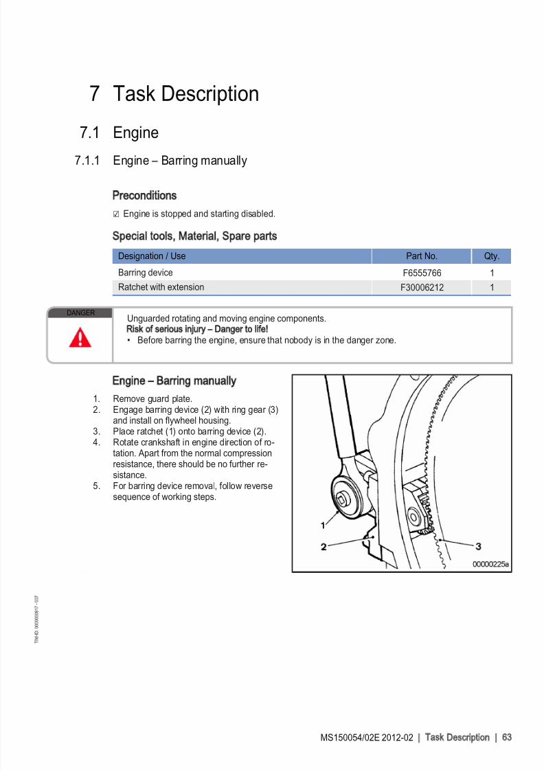
8/10/2019 MS150054_02E.pdf
http://slidepdf.com/reader/full/ms15005402epdf 63/155
7 Task Description
7.1 Engine7.1.1 Engine – Barring manually
Preconditions
☑ Engine is stopped and starting disabled.
Special tools, Material, Spare parts
Designation / Use Part No. Qty.
Barring device F6555766 1
Ratchet with extension F30006212 1
DANGERUnguarded rotating and moving engine components.Risk of serious injury – Danger to life
• Before barring the engine, ensure that nobody is in the danger zone.
Engine – Barring manually
1. Remove guard plate.2. Engage barring device (2) with ring gear (3)
and install on flywheel housing.3. Place ratchet (1) onto barring device (2).4. Rotate crankshaft in engine direction of ro‐
tation. Apart from the normal compressionresistance, there should be no further re‐sistance.
5. For barring device removal, follow reversesequence of working steps.
MS150054/02E 2012-02 | Task Description | 63
T I M - I D : 0 0 0 0 0 0 0 9 1 7 - 0 0 7

8/10/2019 MS150054_02E.pdf
http://slidepdf.com/reader/full/ms15005402epdf 64/155
7.1.2 Engine – Barring with starting system
DANGER
Unguarded rotating and moving engine components.Risk of serious injury – danger to life
• before barring or starting the engine, ensure that nobody is in the danger zone.• After working on the engine, check that all protective devices have been reinstalled and all tools
removed from the engine.
Engine – Barring with starting system
1. Release latch of connector X4.2. Remove connector from engine governor.3. Bar engine in unloaded condition: Press START button.4. Let the crankshaft rotate until oil pressure is indicated.5. Engine start is automatically interrupted when specified starting period has passed. If necessary, re-start
the engine after approx. 20 seconds.6. Connect connector X4 to engine governor and latch in position.
64 | Task Description | MS150054/02E 2012-02
T I M - I D : 0 0 0 0 0 0 0 9 1 8 - 0 0 4

8/10/2019 MS150054_02E.pdf
http://slidepdf.com/reader/full/ms15005402epdf 65/155
7.1.3 Engine – Test run
DANGER
Unguarded rotating and moving engine components.Risk of serious injury – danger to life
• Before barring or starting the engine, make sure that nobody is in the danger zone.
WARNINGEngine noise above 85 dB (A).Risk of damage to hearing
• Wear ear protectors.
Engine – Test run
1. Start engine (→ Page 32).2. Perform test run not below 1/3 load and at least until steady-state temperature is reached.3. Carry out operational checks (→ Page 34).4. Stop engine (→ Page 35).
MS150054/02E 2012-02 | Task Description | 65
T I M - I D : 0 0 0 0 0 0 0 8 7 0 - 0 0 7

8/10/2019 MS150054_02E.pdf
http://slidepdf.com/reader/full/ms15005402epdf 66/155
7.2 Cylinder Liner
7.2.1 Cylinder liner – Endoscopic examination
Preconditions
☑ Engine is stopped and starting disabled.
Special tools, Material, Spare parts
Designation / Use Part No. Qty.
Rigid endoscope Y20097353 1
Preparatory steps
1. Remove cylinder head cover (→ Page 76).2. Remove injector (→ Page 79).
Positioning crankshaft at BDC
1. Using barring device, turn crankshaft until crankshaft journal of the cylinder to be inspected has reachedBDC.
2. Insert endoscope into cylinder liner through injector seat.
Endoscopic examination of cylinder liner
Findings Action
• Thin carbon coating on circumference of carbon scraper ring• Slight localized additive deposits at top edge• Localized smooth areas at bottom edge• Carbon deposits on circumference in clearance between top piston
ring and bottom edge of carbon scraper ring• First signs of marks left by top piston ring• Bright mark on entire circumference• Consistent honing pattern without objections• First signs of marks left by lower cooling bores• Running pattern seems darker
No action required
• Dark areas with even or varying degrees of discoloration• Beginning and end of the discoloration are not sharply defined and
do not cover the entire stroke area• Dark areas in the upper section of the cooling bore, remaining cir‐
cumference without objections• Piston rings without objections
Further endoscopic examina‐tion required as part of main‐
tenance work
• On the entire circumference, apart from light areas of discoloration(that do not impair operation) clearly darker stripes that start at thetop piston ring
• Heat discoloration in the direction of stroke and honing pattern dam‐age
• Heat discoloration of piston rings
Cylinder liner must be re‐placed; Service must be con‐tacted
1. Compile endoscopy report using the table.
2. Use technical terms for description of the liner surface (→ Page 68).3. Depending on findings:• Do not take any action or • carry out a further endoscopic examination as part of maintenance work or • contact Service; cylinder liner must be replaced.
66 | Task Description | MS150054/02E 2012-02
T I M - I D : 0 0 0 0 0 0 0 0 1 5 - 0 1 1

8/10/2019 MS150054_02E.pdf
http://slidepdf.com/reader/full/ms15005402epdf 67/155
Final steps
1. Install injector (→ Page 79).2. Install cylinder head cover (→ Page 76).
MS150054/02E 2012-02 | Task Description | 67
T I M - I D : 0 0 0 0 0 0 0 0 1 5 - 0 1 1

8/10/2019 MS150054_02E.pdf
http://slidepdf.com/reader/full/ms15005402epdf 68/155

8/10/2019 MS150054_02E.pdf
http://slidepdf.com/reader/full/ms15005402epdf 69/155
Findings Measure
Burn mark This is caused by a malfunction in the liner / ring tribosystem. Usually they runover the whole ring-travel area (TDC/BDC), starting at the first TDC-ring andbecoming more visible from the second TDC-ring 2 onwards and less pro‐
nounced from TDC-ring 1. The honing pattern is usually no longer visible anddisplays a clearly defined (straight) edge to the undisturbed surface. The dam‐aged surface is usually discolored. The circumferential length varies.
Liners with burn marks, or heat discoloration, starting in TDC ring 1 have to bereplaced.
Seizure marks, scuff‐ing
Irregular circumference lengths and depths. Can be caused either by the pis‐ton skirt or the piston crown. Material deposits on the liner (smear), heavy dis‐coloration. Severe, visible scoring.
Replace liner.
Evaluation of findings and further measures
The findings in the start phase of oxidation discoloration and heat discoloration are similar. A thoroughinvestigation and compliance with the above evaluation criteria allow an unambiguous evaluation. Toavoid unnecessary disassembly work, it is recommended that another inspection be carried out after fur‐ther operation of the engine.
MS150054/02E 2012-02 | Task Description | 69
T I M - I D : 0 0 0 0 0 0 0 0 1 4 - 0 1 0

8/10/2019 MS150054_02E.pdf
http://slidepdf.com/reader/full/ms15005402epdf 70/155
7.3 Crankcase Breather
7.3.1 Crankcase breather – Oil separator element replacement, diaphragm check
and replacement
Preconditions
☑ Engine is stopped and starting disabled.
Special tools, Material, Spare parts
Designation / Use Part No. Qty.
Torque wrench, 6-50 Nm F30027336 1
Ratchet adapter F30027340 1
Engine oil
Filter element (→ Spare Parts Catalog)
Diaphragm (→ Spare Parts Catalog)
Gasket (→ Spare Parts Catalog)
WARNINGHot oil.Oil can contain combustion residues which are harmful to health.Risk of injury and poisoning
• Wear protective clothing, gloves, and goggles / safety mask.• Avoid contact with skin.
• Do not inhale oil vapor.
Replacing oil separator element
1. Remove cover (2) with O-ring (3).2. Remove filter element (1) from housing (4).3. Insert new filter element in housing (4).4. Install cover (2) with new O-ring.
5. Use torque wrench to tighten the screws of cover (2) to the specified torque.
Name Size Type Lubricant Value/Standard
Screw Tightening torque (Engine oil) 10 Nm − 2 Nm
6. Replace further oil separator elements in the same way.
70 | Task Description | MS150054/02E 2012-02
T I M - I D : 0 0 0 0 0 0 0 0 1 7 - 0 0 6

8/10/2019 MS150054_02E.pdf
http://slidepdf.com/reader/full/ms15005402epdf 71/155

8/10/2019 MS150054_02E.pdf
http://slidepdf.com/reader/full/ms15005402epdf 72/155
7.4 Valve Drive
7.4.1 Valve gear – Lubrication
Preconditions
☑ Engine is stopped and starting disabled.
Special tools, Material, Spare parts
Designation / Use Part No. Qty.
Engine oil
Valve gear – Lubrication
1. Remove cylinder head covers (→ Page 76).2. Fill oil chambers of valve bridges with oil.3. Fill oil chambers of rocker arms and adjust‐
ing screws with oil.4. Install cylinder head covers (→ Page 76).
72 | Task Description | MS150054/02E 2012-02
T I M - I D : 0 0 0 0 0 0 0 9 2 1 - 0 0 7

8/10/2019 MS150054_02E.pdf
http://slidepdf.com/reader/full/ms15005402epdf 73/155
7.4.2 Valve clearance – Check and adjustment
Preconditions
☑ Engine is stopped and starting disabled.
☑ Engine coolant temperature is max. 40 °C.
☑ Valves are closed.
Special tools, Material, Spare parts
Designation / Use Part No. Qty.
Feeler gauge Y20010128 1
Torque wrench, 60-320 Nm F30047446 1
Ring socket, 24 mm F30039526 1
Preparatory steps
1. Remove cylinder head cover (→ Page 76).2. Install barring device (→ Page 63).
3. Rotate crankshaft with barring device in en‐gine direction of rotation until "OT-A1" markand pointer are aligned.
MS150054/02E 2012-02 | Task Description | 73
T I M - I D : 0 0 0 0 0 1 2 2 2 1 - 0 0 3

8/10/2019 MS150054_02E.pdf
http://slidepdf.com/reader/full/ms15005402epdf 74/155
Diagram for 12V engines (two
crankshaft positions)
Diagram for 16V engines (two
crankshaft positions)
Checking valve clearance at two crankshaft positions
1. Check TDC position of piston in cylinder A1:
• If the rocker arms are unloaded on cylinder A1, the piston is in firing TDC.• If the rocker arms are under load on cylinder A1, the piston is in overlap TDC.
2. Check valve clearance with cold engine:• Inlet valves (long rocker arm) = 0.2 mm• Exhaust valves (short rocker arm) = 0.5 mm
3. Check all valve clearances in two crankshaft positions (firing TDC and overlap TDC of cylinder A1) asper diagram.
1 Cylinder A1 is in firing TDC2 Cylinder A1 is in overlap TDCI Inlet valve
X Exhaust valve4. Use feeler gauge to determine the distance between valve bridge and rocker arm.
5. If the deviation from the reference value exceeds 0.1 mm, adjust valve clearance.
74 | Task Description | MS150054/02E 2012-02
T I M - I D : 0 0 0 0 0 1 2 2 2 1 - 0 0 3

8/10/2019 MS150054_02E.pdf
http://slidepdf.com/reader/full/ms15005402epdf 75/155
Adjusting valve clearance
1. Release locknut (1).2. Insert feeler gauge between valve bridge
and rocker arm.3. Using Allen key, set adjusting screw (2) so
that the specified valve clearance is provid‐ed.
4. Feeler gauge must just pass through thegap.
5. Tighten locknut (1) to 90 +9 Nm, holdingadjusting screw (2) firmly.
6. Replace or rectify adjusting screws and/or locknuts which do not move freely.
7. Check valve clearance.
Final steps
1. Remove barring device (→ Page 63).2. Install cylinder head cover (→ Page 76).
MS150054/02E 2012-02 | Task Description | 75
T I M - I D : 0 0 0 0 0 1 2 2 2 1 - 0 0 3

8/10/2019 MS150054_02E.pdf
http://slidepdf.com/reader/full/ms15005402epdf 76/155
7.4.3 Cylinder head cover – Removal and installation
Preconditions
☑ Engine is stopped and starting disabled.
Special tools, Material, Spare parts
Designation / Use Part No. Qty.
Grease (Kluthe Hakuform 30-10/Emulgier) X00058061
O-ring (→ Spare Parts Catalog)
Removing cylinder head cover
1. Clean very dirty cylinder head covers (3)
prior to removal.2. Remove screws (1) and washers (2).3. Take off cylinder head cover (3) with O-
ring (4) from cylinder head (5).
Installing cylinder head cover
1. Clean mounting surface.2. Check O-ring (4) for damage, replace if necessary.3. Coat O-ring (4) with grease.4. Position O-ring (4) in groove of cylinder head cover (3).5. Fit cylinder head cover (3) on cylinder head (5).6. Install cylinder head cover (3) with screws (1) and washers (2).
76 | Task Description | MS150054/02E 2012-02
T I M - I D : 0 0 0 0 0 1 2 3 0 9 - 0 0 7

8/10/2019 MS150054_02E.pdf
http://slidepdf.com/reader/full/ms15005402epdf 77/155
7.5 Injection Pump / HP Pump
7.5.1 HP pump – Filling with engine oil
Preconditions
☑ Engine is stopped and starting disabled.
Special tools, Material, Spare parts
Designation / Use Part No. Qty.
Engine oil
WARNINGFuels are combustible.
Risk of fire and explosion
• Avoid open flames, electrical sparks and ignition sources.• Do not smoke.
WARNINGOils/oil vapors are combustible.Risk of fire
• No open flames, no electric sparks. Do not smoke. Avoid ignition sources.
CAUTIONFuel system high-pressure pump not filled with engine oil.Damage to components, major material damage
• Make sure that the high-pressure fuel pump is filled with engine oil before installation or initialoperation.
Filling HP pump
1. Fill fresh engine oil into a clean receptacle.2. Fill HP pump (1) at connection (2).
MS150054/02E 2012-02 | Task Description | 77
T I M - I D : 0 0 0 0 0 0 1 6 4 0 - 0 0 7

8/10/2019 MS150054_02E.pdf
http://slidepdf.com/reader/full/ms15005402epdf 78/155
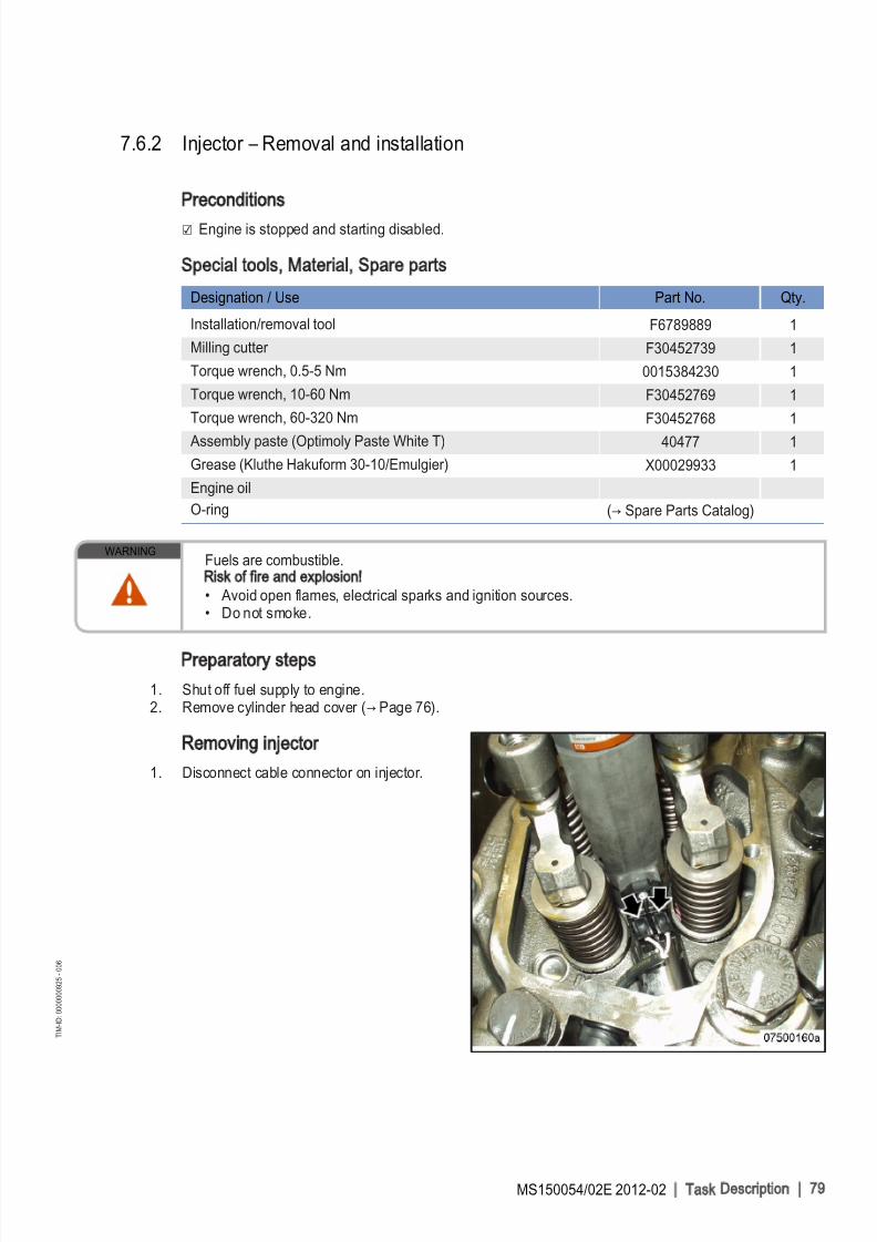
8/10/2019 MS150054_02E.pdf
http://slidepdf.com/reader/full/ms15005402epdf 79/155
7.6.2 Injector – Removal and installation
Preconditions
☑ Engine is stopped and starting disabled.
Special tools, Material, Spare parts
Designation / Use Part No. Qty.
Installation/removal tool F6789889 1
Milling cutter F30452739 1
Torque wrench, 0.5-5 Nm 0015384230 1
Torque wrench, 10-60 Nm F30452769 1
Torque wrench, 60-320 Nm F30452768 1
Assembly paste (Optimoly Paste White T) 40477 1
Grease (Kluthe Hakuform 30-10/Emulgier) X00029933 1
Engine oil
O-ring (→ Spare Parts Catalog)
WARNINGFuels are combustible.Risk of fire and explosion
• Avoid open flames, electrical sparks and ignition sources.• Do not smoke.
Preparatory steps
1. Shut off fuel supply to engine.2. Remove cylinder head cover (→ Page 76).
Removing injector
1. Disconnect cable connector on injector.
MS150054/02E 2012-02 | Task Description | 79
T I M - I D : 0 0 0 0 0 0 0 9 2 5 - 0 0 6

8/10/2019 MS150054_02E.pdf
http://slidepdf.com/reader/full/ms15005402epdf 80/155
2. Remove HP fuel line (4).3. Remove return line (5).
Note: The injector accumulator will be emptiedwhen removing the adapter.
4. Remove adapter (3).5. Remove screw (2) and take off hold-down
clamp (1).
6. Install installation/removal tool on cylinder head.
7. Remove injector with installation/removaltool.
8. Remove installation/removal tool.
9. Remove sealing ring (4) from injector or usea self-made hook to take it out of the cylin‐der head.
10. Remove O-rings (3), O-ring (2) and damper
ring (1) from injector.11. Clean all mating and sealing surfaces.12. Cover all connections and bores, or seal
with suitable plugs.
80 | Task Description | MS150054/02E 2012-02
T I M - I D : 0 0 0 0 0 0 0 9 2 5 - 0 0 6

8/10/2019 MS150054_02E.pdf
http://slidepdf.com/reader/full/ms15005402epdf 81/155
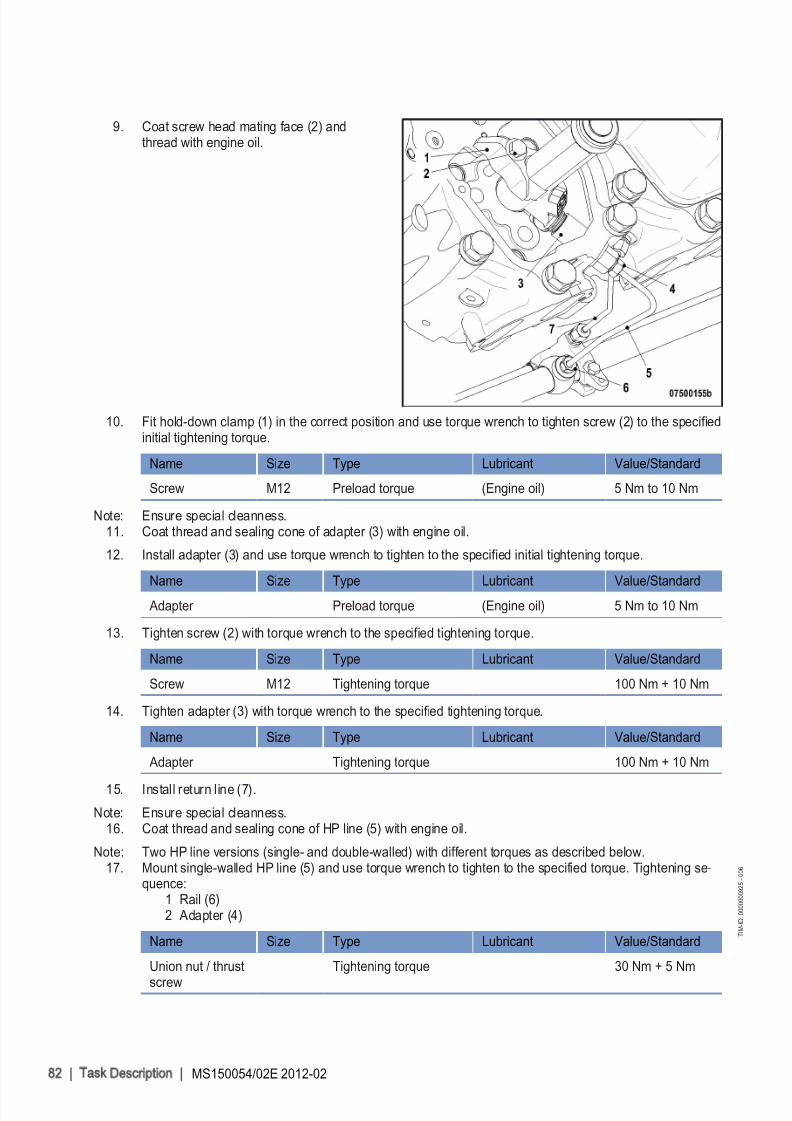
8/10/2019 MS150054_02E.pdf
http://slidepdf.com/reader/full/ms15005402epdf 82/155
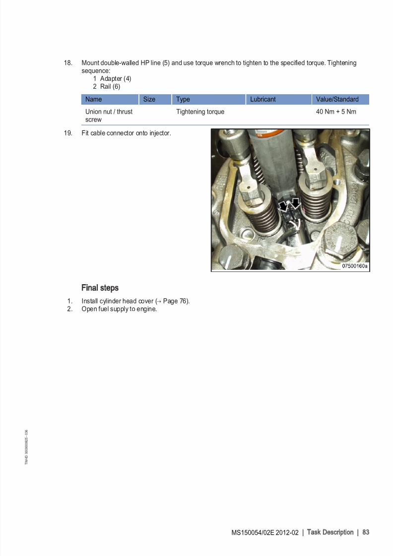
8/10/2019 MS150054_02E.pdf
http://slidepdf.com/reader/full/ms15005402epdf 83/155

8/10/2019 MS150054_02E.pdf
http://slidepdf.com/reader/full/ms15005402epdf 84/155
7.7 Fuel System
7.7.1 Fuel system – Venting
Preconditions
☑ Engine is stopped and starting disabled.
Special tools, Material, Spare parts
Designation / Use Part No. Qty.
Diesel fuel
WARNINGFuels are combustible.
Risk of fire and explosion
• Avoid open flames, electrical sparks and ignition sources.• Do not smoke.
Venting LP fuel system
1. Open threaded vent plug (1).2. Unlock fuel priming pump (2), screw out
handle by turning it counterclockwise.3. Operate the pump with the handle (2) until
bubble-free fuel emerges at the threadedvent plug (1).
4. Close threaded vent plug (1).5. Screw in handle by turning it clockwise.6. Verify that fuel priming pump (2) is locked:
Handle must be tightened.
84 | Task Description | MS150054/02E 2012-02
T I M - I D : 0 0 0 0 0 0 4 7 0 9 - 0 0 5

8/10/2019 MS150054_02E.pdf
http://slidepdf.com/reader/full/ms15005402epdf 85/155
7.8 Fuel Filter
7.8.1 Fuel filter – Replacement
Preconditions
☑ Engine is stopped and starting disabled.
Special tools, Material, Spare parts
Designation / Use Part No. Qty.
Filter wrench F30379104 1
Engine oil
Easy-change filter (→ Spare Parts Catalog)
WARNINGFuels are combustible.Risk of fire and explosion
• Avoid open flames, electrical sparks and ignition sources.• Do not smoke.
Replacing fuel filter
1. Remove easy-change filter using filter wrench.
2. Clean sealing surface on filter head.
3. Slightly lubricate seal on the easy-changefilter.
4. Screw on easy-change filter by hand untilthe seal connects and tighten manually.
5. Vent fuel system (→ Page 84).6. Replace other easy-change filters in the
same way.
MS150054/02E 2012-02 | Task Description | 85
T I M - I D : 0 0 0 0 0 0 0 9 2 7 - 0 0 3

8/10/2019 MS150054_02E.pdf
http://slidepdf.com/reader/full/ms15005402epdf 86/155
7.8.2 Fuel prefilter cleaning
Preconditions
☑ Engine is stopped and starting disabled.
Special tools, Material, Spare parts
Designation / Use Part No. Qty.
Diesel fuel
Sealing ring (→ Spare Parts Catalog)
WARNINGFuels are combustible.Risk of fire and explosion
• Avoid open flames, electrical sparks and ignition sources.• Do not smoke.
Fuel prefilter cleaning
1. Shut off fuel supply.2. Remove nuts from filter head.3. Take off filter housing and drain fuel into
appropriate container.4. Remove filter-element securing nut and re‐
move filter element by pulling it downwards.5. Wash filter element in clean fuel using a
smooth brush.6. Wash filter housing with clean fuel.7. Insert filter element into filter housing and
secure with nut.8. Place new sealing ring into groove in filter
head.9. Fit cover with seal and secure it with nuts
crosswise.10. Open fuel supply.
86 | Task Description | MS150054/02E 2012-02
T I M - I D : 0 0 0 0 0 0 4 9 3 6 - 0 0 1

8/10/2019 MS150054_02E.pdf
http://slidepdf.com/reader/full/ms15005402epdf 87/155
7.8.3 Fuel prefilter – Differential pressure gauge check and adjustment
DANGER
Unguarded rotating and moving engine components.Risk of serious injury – danger to life
• Take special care when working on a running engine.
WARNINGEngine noise above 85 dB (A).Risk of damage to hearing
• Wear ear protectors.
Adjusting differential pressure
gauge
1. When installing the new filter element: alignadjustable pointer (2) with pressure-indicat‐ing pointer (3) of pressure gauge (1).
2. Check differential pressure.
Checking differential pressure of fuel prefilter
1. With the engine running at full load or rated power, read off pressure at gauge (1).2. If differential pressure as indicated between position of adjustable pointer (2) and pressure-indicating
pointer (3) of pressure gauge is ≥ 0.3 bar, flush filter element of the cut-in filter (→ Page 89).
MS150054/02E 2012-02 | Task Description | 87
T I M - I D : 0 0 0 0 0 0 4 9 2 5 - 0 0 4

8/10/2019 MS150054_02E.pdf
http://slidepdf.com/reader/full/ms15005402epdf 88/155

8/10/2019 MS150054_02E.pdf
http://slidepdf.com/reader/full/ms15005402epdf 89/155

8/10/2019 MS150054_02E.pdf
http://slidepdf.com/reader/full/ms15005402epdf 90/155
2. Open threaded vent plug (5) of filter to beflushed.
3. Unlock drain valve (6) by pressing toggle,open it and drain fuel.
Result: Fuel flows from filtered side back to the un‐filtered side, flushing the filter depositsdownwards out of the filter.
4. Close threaded vent plug (5) and drainvalve (6).
Fuel prefilter – Topping up with fuel
1. Stop engine (→ Page 35) and disable engine start.2. Remove screws for cover and take off cover (2).3. Fill filter housing with clean fuel.4. Place new gasket in cover (2).5. Fit cover with gasket and secure it with screws.6. Check differential pressure (→ Page 87).
Result: If flushing did not lead to an improvement of the differential pressure, replace filter element of fuel prefil‐ter (→ Page 91).
90 | Task Description | MS150054/02E 2012-02
T I M - I D : 0 0 0 0 0 0 4 9 3 7 - 0 1 2

8/10/2019 MS150054_02E.pdf
http://slidepdf.com/reader/full/ms15005402epdf 91/155
7.8.6 Fuel prefilter – Filter element replacement
Preconditions
☑ Engine is stopped and starting disabled.
Special tools, Material, Spare parts
Designation / Use Part No. Qty.
Diesel fuel
Filter element (→ Spare Parts Catalog)
Gasket (→ Spare Parts Catalog)
WARNINGFuels are combustible.
Risk of fire and explosion
• Avoid open flames, electrical sparks and ignition sources.• Do not smoke.
Replacing filter element
1. Cut out filter to be drained.I Left filter cut in
II Right filter cut in
MS150054/02E 2012-02 | Task Description | 91
T I M - I D : 0 0 0 0 0 0 4 9 4 4 - 0 0 3

8/10/2019 MS150054_02E.pdf
http://slidepdf.com/reader/full/ms15005402epdf 92/155

8/10/2019 MS150054_02E.pdf
http://slidepdf.com/reader/full/ms15005402epdf 93/155

8/10/2019 MS150054_02E.pdf
http://slidepdf.com/reader/full/ms15005402epdf 94/155

8/10/2019 MS150054_02E.pdf
http://slidepdf.com/reader/full/ms15005402epdf 95/155

8/10/2019 MS150054_02E.pdf
http://slidepdf.com/reader/full/ms15005402epdf 96/155
7.10.3 Rubber sleeves between air intake elbow and turbocharger – Replacement
Preconditions
☑ Engine is stopped and starting disabled.
Special tools, Material, Spare parts
Designation / Use Part No. Qty.
Rubber sleeve (→ Spare Parts Catalog) 4
Also applicable to 12 V
Preparatory steps
u Remove air filter (→ Page 94).
Replacing rubber sleeves
1. Remove screws (3), loosen clamps (1) and take off elbow (4).2. Pull off rubber sleeve (2) from turbocharger intake flange.3. Clean connecting flange of turbocharger and check for obstructions.4. Fit new rubber sleeve (2) on turbocharger intake flange.
5. Fit both clamps (1) on rubber sleeve (2), slide on elbow (4) and secure with screws (3).6. Align clamps (1) and tighten.7. Replace further rubber sleeves in the same way.
Final steps
u Install air filter (→ Page 94).
96 | Task Description | MS150054/02E 2012-02
T I M - I D : 0 0 0 0 0 1 3 4 0 4 - 0 0 2

8/10/2019 MS150054_02E.pdf
http://slidepdf.com/reader/full/ms15005402epdf 97/155
7.11 Air Intake
7.11.1 Contamination indicator – Signal ring position check
Preconditions
☑ Engine is stopped and starting disabled.
Checking signal ring pos ition
1. If the signal ring is completely visible in thecontrol window (2), replace air filter (→ Page 94).
2. After installation of new filter, press resetbutton (1).
Result: Engaged piston with signal ring moves backto initial position.
MS150054/02E 2012-02 | Task Description | 97
T I M - I D : 0 0 0 0 0 0 5 4 8 4 - 0 0 5

8/10/2019 MS150054_02E.pdf
http://slidepdf.com/reader/full/ms15005402epdf 98/155
7.11.2 Emergency air-shutoff flaps – Functional check with electric actuation
DANGER
Unguarded rotating and moving engine components.Risk of serious injury – danger to life
• Before barring or starting the engine, make sure that nobody is in the danger zone.
WARNINGAir flaps close abruptly.Risk of injury
• Before actuating, ensure that nobody is in the danger zone.
WARNINGEngine noise above 85 dB (A).
Risk of damage to hearing• Wear ear protectors.
Emergency air-shutoff flaps –
Functional check with electric
actuation
1. Start engine (→ Page 32).2. Activate the appropriate function to trigger
emergency air-shutoff flaps (depending oninstallation), e.g. by carrying out overspeed
test. Check the following items:• The emergency air-shutoff flaps must
close as soon as the set point isreached.
• The levers must be in position B.• Emergency engine stop must be initiat‐
ed.3. Open the emergency air-shutoff flaps man‐
ually after completion of test so that the lev‐ers are in position A.
4. Observe fault message.
98 | Task Description | MS150054/02E 2012-02
T I M - I D : 0 0 0 0 0 1 3 4 3 5 - 0 0 1

8/10/2019 MS150054_02E.pdf
http://slidepdf.com/reader/full/ms15005402epdf 99/155
7.11.3 Rubber sleeves in air pipework before intercooler – Replacement
Preconditions
☑ Engine is stopped and starting disabled.
Special tools, Material, Spare parts
Designation / Use Part No. Qty.
Rubber sleeve (→ Spare Parts Catalog)
O-ring (→ Spare Parts Catalog)
Also applicable to 12 V
Preparatory steps
u Remove air filter (→ Page 94).
Replacing rubber sleeves on right engine side
1. Release clamps (1).2. Remove screws from elbow (8), remove elbow and pull off rubber sleeves (2).
3. Remove charge-air pipe (9), pull off rubber sleeve (2).4. Clean charge-air pipe and elbow and check for obstructions.5. Fit new rubber sleeves on exhaust turbocharger and charge-air pipe.6. Slide clamps onto all rubber sleeves.7. Insert elbow (8) and charge-air pipe (9) ends into rubber sleeves.8. Secure elbow (8) with new O-ring on intercooler.9. Align clamps (1) and secure.
MS150054/02E 2012-02 | Task Description | 99
T I M - I D : 0 0 0 0 0 1 3 6 1 4 - 0 0 2

8/10/2019 MS150054_02E.pdf
http://slidepdf.com/reader/full/ms15005402epdf 100/155
Replacing rubber sleeves on left engine side
1. Release clamps (3).2. Remove retainer (5) on charge-air pipe.3. Remove screws from elbow (7) and remove elbow.4. Pull off charge-air pipe (6).5. Clean charge-air pipe and elbow and check for obstructions.6. Slide new rubber sleeves (4) onto exhaust turbocharger and charge-air pipe (6).7. Slide clamps onto all rubber sleeves.8. Insert elbow (7) and charge-air pipe (6) ends into rubber sleeves.9. Secure elbow (7) with new O-ring on intercooler.
10. Align clamps (3) and secure.11. Install retainer (5) on charge-air pipe (6).
Final steps
u Install air filter (→ Page 94).
100 | Task D escription | MS150054/02E 2012-02
T I M - I D : 0 0 0 0 0 1 3 6 1 4 - 0 0 2

8/10/2019 MS150054_02E.pdf
http://slidepdf.com/reader/full/ms15005402epdf 101/155
7.12 Starting Equipment
7.12.1 Air starter – Manual operation
DANGERUnguarded rotating and moving engine components.Risk of serious injury – danger to life
• Before barring or starting the engine, make sure that nobody is in the danger zone.
WARNINGEngine noise above 85 dB (A).Risk of damage to hearing
• Wear ear protectors.
Air starter – Manual operation
1. Operate pushbutton for manual start (ar‐row) and hold.
2. Allow compressed air to enter the air start‐er, until the engine fires evenly.
3. Release pushbutton.
MS150054/02E 2012-02 | Task Description | 101
T I M - I D : 0 0 0 0 0 0 6 0 7 7 - 0 0 1

8/10/2019 MS150054_02E.pdf
http://slidepdf.com/reader/full/ms15005402epdf 102/155
7.13 Lube Oil System, Lube Oil Circuit
7.13.1 Engine oil level – Check
Preconditions
☑ Engine shut down and starting disabled.
Checking oil level prior to engine
start
1. Withdraw oil dipstick from guide tube andwipe it.
2. Insert oil dipstick into guide tube up to stop,withdraw after approx. 10 seconds and
check oil level.
Note: After extended standstill, the oil level mayexceed the mark (1) by up to 2 cm. Thiscan be caused by oil flowing from e.g. oil fil‐ter or heat exchanger back to the oil pan.
3. The oil level must reach mark (1) or exceedmark (1) by up to 2 cm.
4. Top up with oil to mark (1) as necessary(→ Page 103).
5. Insert oil dipstick into guide tube up to thestop.
Checking oil level after the engine is stopped
1. 5 minutes after stopping the engine, remove oil dipstick from the guide tube and wipe it.2. Insert oil dipstick into guide tube up to stop, withdraw after approx. 10 seconds and check oil level.3. Oil level must be between marks (1) and (2).4. Top up with oil to mark (1) as necessary (→ Page 103).5. Insert oil dipstick into guide tube up to the stop.
102 | Task D escription | MS150054/02E 2012-02
T I M - I D : 0 0 0 0 0 0 0 9 3 1 - 0 0 9

8/10/2019 MS150054_02E.pdf
http://slidepdf.com/reader/full/ms15005402epdf 103/155

8/10/2019 MS150054_02E.pdf
http://slidepdf.com/reader/full/ms15005402epdf 104/155

8/10/2019 MS150054_02E.pdf
http://slidepdf.com/reader/full/ms15005402epdf 105/155
7.13.3 Engine-oil – Sample extraction and analysis
Preconditions
☑ MTU Fluids and Lubricants Specifications (A001061/..) are available.
Special tools, Material, Spare parts
Designation / Use Part No. Qty.
MTU test kit 5605892099/00 1
DANGERUnguarded rotating and moving engine components.Risk of serious injury – danger to life
• Take special care when working on a running engine.
WARNINGHot oil.Oil can contain combustion residues which are harmful to health.Risk of injury and poisoning
• Wear protective clothing, gloves, and goggles / safety mask.• Avoid contact with skin.• Do not inhale oil vapor.
WARNINGEngine noise above 85 dB (A).Risk of damage to hearing
• Wear ear protectors.
Engine-oil sample extraction and
analysis, variant A
1. With the engine running at operating tem‐perature, open screw on flange of centrifu‐gal oil filter by 1 to 2 rotations.
2. Drain approx. 2 liters engine oil to flush outthe oil sludge.
3. Drain approx. 1 liter engine oil into a clean
container.4. Close screw.5. Using the equipment and chemicals of the
MTU test kit, examine oil for:• Dispersion capability (spot test);• Water content;• Dilution by fuel.
MS150054/02E 2012-02 | Task Description | 105
T I M - I D : 0 0 0 0 0 1 4 1 1 1 - 0 0 1

8/10/2019 MS150054_02E.pdf
http://slidepdf.com/reader/full/ms15005402epdf 106/155

8/10/2019 MS150054_02E.pdf
http://slidepdf.com/reader/full/ms15005402epdf 107/155
7.14 Oil Filtration / Cooling
7.14.1 Engine oil filter – Replacement
Preconditions
☑ Engine is stopped and starting disabled.
Special tools, Material, Spare parts
Designation / Use Part No. Qty.
Filter wrench F30379104
Engine oil
Oil filter (→ Spare Parts Catalog)
WARNINGHot oil.Oil can contain combustion residues which are harmful to health.Risk of injury and poisoning
• Wear protective clothing, gloves, and goggles / safety mask.• Avoid contact with skin.• Do not inhale oil vapor.
Engine oil filter – Replacement
1. Remove engine oil filter using filter wrench.
2. Clean sealing surface on connecting piece.3. Check condition of new engine oil filter
sealing ring and coat it with engine oil.4. Screw on and tighten new engine oil filter
by hand.5. Replace further engine oil filters in the
same way.6. Check engine oil level (→ Page 102).7. After oil change and oil filter replacement,
bar engine with starting system(→ Page 64).
MS150054/02E 2012-02 | Task Description | 107
T I M - I D : 0 0 0 0 0 0 0 9 5 7 - 0 0 3

8/10/2019 MS150054_02E.pdf
http://slidepdf.com/reader/full/ms15005402epdf 108/155

8/10/2019 MS150054_02E.pdf
http://slidepdf.com/reader/full/ms15005402epdf 109/155
3. Withdraw filter insert (1).4. Remove O-ring.
5. Remove screw (2).6. Withdraw spinner (1) with spring.7. Remove nut (3).8. Take off spring washer and washer.9. Remove screw (4).
10. Remove flushing arm (5) from screenplate (6).
11. Turn filter insert upside down and use ap‐propriate tool to push out filter candles (1).
12. Turn filter insert by 180° and insert new fil‐ter candles (1) with chamfer facing down‐
wards.
MS150054/02E 2012-02 | Task Description | 109
T I M - I D : 0 0 0 0 0 0 6 4 0 1 - 0 0 3

8/10/2019 MS150054_02E.pdf
http://slidepdf.com/reader/full/ms15005402epdf 110/155
Oil filter candles – Installation
1. For installation follow reverse sequence of working steps.2. In addition, the following work must be performed:
• Replace all sealing elements with new parts.• Coat O-rings with grease.• Insert O-rings in grooves.• Pay attention to installation position of fillister-head screw to slot in shaft.
110 | Task D escription | MS150054/02E 2012-02
T I M - I D : 0 0 0 0 0 0 6 4 0 1 - 0 0 3

8/10/2019 MS150054_02E.pdf
http://slidepdf.com/reader/full/ms15005402epdf 111/155
7.14.3 Oil indicator filter – Check
Preconditions
☑ Engine is stopped and starting disabled.
Special tools, Material, Spare parts
Designation / Use Part No. Qty.
Strainer (→ Spare Parts Catalog)
Square-section ring (→ Spare Parts Catalog)
O-ring (→ Spare Parts Catalog)
WARNINGHot oil.
Oil can contain combustion residues which are harmful to health.Risk of injury and poisoning
• Wear protective clothing, gloves, and goggles / safety mask.• Avoid contact with skin.• Do not inhale oil vapor.
WARNINGCompressed air Risk of injury
• Do not direct compressed-air jet at persons.• Wear protective goggles / safety mask and ear protectors.
CAUTION Unsuitable cleaning tool.Damage to component
• Observe manufacturer's instructions.• Use appropriate cleaning tool.
Removing strainer
1. Clean oil indicator filter before disassem‐bling it.
2. Remove screws (1).3. Take off cover (2) with O–ring (3).4. Take strainer (5) from filter housing.
MS150054/02E 2012-02 | Task Description | 111
T I M - I D : 0 0 0 0 0 0 6 4 0 2 - 0 0 1

8/10/2019 MS150054_02E.pdf
http://slidepdf.com/reader/full/ms15005402epdf 112/155
Checking strainer
Item Findings Task
Strainer Metallic residues • Clean
• Monitor engine operation• Check strainer daily• Contact Service.
Strainer Damaged Replace
Square-section ring Damaged Replace
O-ring Damaged Replace
Cleaning strainer
1. Wash strainer (5) with cleaner.2. Remove stubborn deposits with soft brush.3. Blow out strainer (5) with compressed air from inside.
Installing strainer
1. Coat square-section ring (4) on strainer (5) with engine oil and install strainer (5).2. Coat O–ring (3) with engine oil and fit in filter housing.3. Fit cover (2) and secure with screws (1) and washers.
112 | Task D escription | MS150054/02E 2012-02
T I M - I D : 0 0 0 0 0 0 6 4 0 2 - 0 0 1

8/10/2019 MS150054_02E.pdf
http://slidepdf.com/reader/full/ms15005402epdf 113/155
7.14.4 Centrifugal oil filter – Cleaning and filter-sleeve replacement
Preconditions
☑ Engine is stopped and starting disabled.
Special tools, Material, Spare parts
Designation / Use Part No. Qty.
Torque wrench 6-50 Nm F30027336 1
Filter wrench F30379104 1
Cold cleaner (Hakutex 60) 50602 1
Grease (Kluthe Hakuform 30-10/Emulgier) X00029933 1
Filter sleeve (→ Spare Parts Catalog)
Sealing ring (→ Spare Parts Catalog)
Sealing ring (→ Spare Parts Catalog)
Sealing ring (→ Spare Parts Catalog)
WARNINGHot oil.Oil can contain combustion residues which are harmful to health.Risk of injury and poisoning
• Wear protective clothing, gloves, and goggles / safety mask.• Avoid contact with skin.• Do not inhale oil vapor.
WARNINGCompressed air Risk of injury
• Do not direct compressed-air jet at persons.• Wear protective goggles / safety mask and ear protectors.
MS150054/02E 2012-02 | Task Description | 113
T I M - I D : 0 0 0 0 0 1 4 2 5 2 - 0 0 1
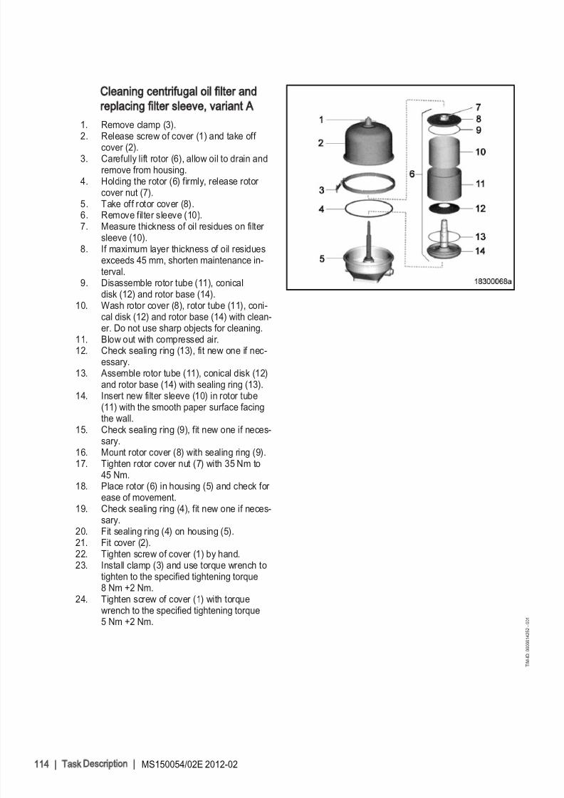
8/10/2019 MS150054_02E.pdf
http://slidepdf.com/reader/full/ms15005402epdf 114/155
Cleaning centrifugal oil filter and
replacing filter sleeve, variant A
1. Remove clamp (3).
2. Release screw of cover (1) and take off cover (2).3. Carefully lift rotor (6), allow oil to drain and
remove from housing.4. Holding the rotor (6) firmly, release rotor
cover nut (7).5. Take off rotor cover (8).6. Remove filter sleeve (10).7. Measure thickness of oil residues on filter
sleeve (10).8. If maximum layer thickness of oil residues
exceeds 45 mm, shorten maintenance in‐terval.
9. Disassemble rotor tube (11), conicaldisk (12) and rotor base (14).
10. Wash rotor cover (8), rotor tube (11), coni‐cal disk (12) and rotor base (14) with clean‐er. Do not use sharp objects for cleaning.
11. Blow out with compressed air.12. Check sealing ring (13), fit new one if nec‐
essary.13. Assemble rotor tube (11), conical disk (12)
and rotor base (14) with sealing ring (13).14. Insert new filter sleeve (10) in rotor tube
(11) with the smooth paper surface facing
the wall.15. Check sealing ring (9), fit new one if neces‐
sary.16. Mount rotor cover (8) with sealing ring (9).17. Tighten rotor cover nut (7) with 35 Nm to
45 Nm.18. Place rotor (6) in housing (5) and check for
ease of movement.19. Check sealing ring (4), fit new one if neces‐
sary.20. Fit sealing ring (4) on housing (5).21. Fit cover (2).22. Tighten screw of cover (1) by hand.23. Install clamp (3) and use torque wrench to
tighten to the specified tightening torque8 Nm +2 Nm.
24. Tighten screw of cover (1) with torquewrench to the specified tightening torque5 Nm +2 Nm.
114 | Task D escription | MS150054/02E 2012-02
T I M - I D : 0 0 0 0 0 1 4 2 5 2 - 0 0 1

8/10/2019 MS150054_02E.pdf
http://slidepdf.com/reader/full/ms15005402epdf 115/155
Cleaning centrifugal oil filter and
replacing filter sleeve, variant B
1. Release screw (1) and remove.
2. Remove clamp (3) and take off cover (2).3. Carefully remove rotor (5) from housing.4. Holding the rotor (5) firmly with the filter
wrench, release knurled nut (7).5. Take off rotor cap (8).6. Remove filter sleeve (9), stiffener plate (10)
and sealing ring (11).7. Measure thickness of oil residues on filter
sleeve.8. If maximum layer thickness of oil residues
exceeds 30 mm, shorten maintenance in‐terval.
9. Take off standpipe (12) from lower rotor
section (13).10. Wash cover (2), rotor cap (8), stiffener plate
(10), standpipe (12), lower rotor section(13) and nozzles (14) with cleaner and blowout with compressed air. Do not use sharpobjects for cleaning.
11. Check nozzles (14) for obstructions.12. Move standpipe (12) over rotor lower sec‐
tion (13).13. Insert new filter sleeve (9) with stiffener
plate (10) into rotor cap (8) with the with thesmooth paper surface of the filter sleeve (9)
facing the rotor cap (8).14. Check sealing ring (11), fit new one if nec‐
essary. Coat sealing ring with grease andinsert in the groove of the rotor cap (8).
15. Place rotor cap (8) onto standpipe (12).16. Holding the rotor (5) firmly with the filter
wrench, tighten knurled nut (7).17. Lubricate bearings of rotor (5), insert in
housing (6) and check for ease of move‐ment.
18. Check sealing ring (4), fit new one if neces‐sary. Fit sealing ring on housing (6).
19. Fit cover (2).20. Tighten screw (1) by hand.21. Install clamp (3) and use torque wrench to
tighten to the specified tightening torque6 Nm +1 Nm.
22. Tighten screw (1) with torque wrench to thespecified tightening torque 6 Nm +1 Nm.
MS150054/02E 2012-02 | Task Description | 115
T I M - I D : 0 0 0 0 0 1 4 2 5 2 - 0 0 1

8/10/2019 MS150054_02E.pdf
http://slidepdf.com/reader/full/ms15005402epdf 116/155
7.15 Coolant Circuit, General, High-Temperature Circuit
7.15.1 Engine coolant – Level check
Preconditions
☑ Engine is stopped and starting disabled.
☑ MTU Fluids and Lubricants Specifications (A001061/..) are available.
WARNINGCoolant is hot and under pressure.Risk of injury and scalding
• Let the engine cool down.• Wear protective clothing, gloves, and goggles / safety mask.
Checking engine coolant level at filler neck:
1. Turn breather valve on coolant expansion tank counterclockwise to the first stop and allow pressure toescape.
2. Continue to turn breather valve counterclockwise and remove.3. Check coolant level (coolant must be visible at the lower edge of the cast-in eye).
Checking engine coolant level at
remote cooler:
1. Check coolant level (coolant must be visibleat marking plate).
2. Top up coolant if necessary (→ Page 120).3. Check and clean breather valve.4. Place breather valve on filler neck and
close.
Checking engine coolant level via level sensor:
1. Switch on engine control system and check readings on the display.2. Top up coolant if necessary (→ Page 120).
116 | Task D escription | MS150054/02E 2012-02
T I M - I D : 0 0 0 0 0 0 0 9 3 7 - 0 1 1

8/10/2019 MS150054_02E.pdf
http://slidepdf.com/reader/full/ms15005402epdf 117/155
7.15.2 Engine coolant – Change
Special tools, Material, Spare parts
Designation / Use Part No. Qty.
Engine coolant
Changing engine coolant
1. Drain engine coolant (→ Page 118).2. Fill with engine coolant (→ Page 120).
MS150054/02E 2012-02 | Task Description | 117
T I M - I D : 0 0 0 0 0 0 0 0 3 6 - 0 2 6

8/10/2019 MS150054_02E.pdf
http://slidepdf.com/reader/full/ms15005402epdf 118/155

8/10/2019 MS150054_02E.pdf
http://slidepdf.com/reader/full/ms15005402epdf 119/155
5. Drain pint on driving end, left and right side.
Final steps
1. Close all drain valves and install drain plugs with new sealing rings.2. Set breather valve onto filler neck and close it.
MS150054/02E 2012-02 | Task Description | 119
T I M - I D : 0 0 0 0 0 1 4 5 7 7 - 0 0 1

8/10/2019 MS150054_02E.pdf
http://slidepdf.com/reader/full/ms15005402epdf 120/155
7.15.4 Engine coolant – Filling
Preconditions
☑ Engine is stopped and starting disabled.
☑ MTU Fluids and Lubricants Specifications (A001061/..) are available.
Special tools, Material, Spare parts
Designation / Use Part No. Qty.
Coolant
WARNINGCoolant is hot and under pressure.Risk of injury and scalding
• Let the engine cool down.• Wear protective clothing, gloves, and goggles / safety mask.
CAUTIONCold coolant in hot engine can cause thermal stress.Formation of cracks in components
• Fill / top up coolant only into cold engine.
Preparatory steps
1. Turn breather valve of coolant expansion
tank counterclockwise until the first stopand allow pressure to escape.2. Continue to turn breather valve counter‐
clockwise and remove.
120 | Task D escription | MS150054/02E 2012-02
T I M - I D : 0 0 0 0 0 1 4 5 5 5 - 0 0 3

8/10/2019 MS150054_02E.pdf
http://slidepdf.com/reader/full/ms15005402epdf 121/155
Filling coolant with pump
1. Connect a suitable pump with a hose to thedrain valve of the engine coolant pump (ar‐row).
2. Release union at distributor (arrow).3. Open drain valve and pump coolant into en‐
gine at 0.5 bar minimum.4. Close venting point when coolant emerges
from the released union.5. Fill expansion tank until overflow edge is
reached.6. Close drain valve.7. Check proper condition of breather valve,
clean sealing faces if required.8. Fit breather valve and close it.9. Start engine (→ Page 32).
10. After the engine has run at unloaded condi‐tion for10 seconds, stop engine(→ Page 35).
11. Turn breather valve of coolant expansiontank counterclockwise until the first stopand allow pressure to escape.
12. Continue to turn breather valve counter‐clockwise and remove.
13. Check coolant level (→ Page 116) and topup engine coolant as required:
a) Fill in coolant via filler neck on expan‐
sion tank until the coolant level at bot‐tom edge of filler neck remains con‐stant.
b) Check proper condition of breather valve, clean sealing faces if required.
c) Fit breather valve and close it.14. Repeat the steps from "Start engine"
(→ Step 8) until coolant no longer needs tobe topped up.
15. Disconnect pump and hose.
MS150054/02E 2012-02 | Task Description | 121
T I M - I D : 0 0 0 0 0 1 4 5 5 5 - 0 0 3

8/10/2019 MS150054_02E.pdf
http://slidepdf.com/reader/full/ms15005402epdf 122/155
Alternatively: Filling coolant
through filler neck
1. Release union at distributor (arrow).
2. Fill in coolant via filler neck on expansiontank until the coolant emerges from the re‐leased union.
3. Tighten union (arrow).4. Fill expansion tank until overflow edge is
reached.5. Check proper condition of breather valve,
clean sealing faces if required.6. Fit breather valve and close it.7. Start engine (→ Page 32).8. After the engine has run at unloaded condi‐
tion for10 seconds, stop engine(→ Page 35).
9. Turn breather valve of coolant expansiontank counterclockwise until the first stopand allow pressure to escape.
10. Turn breather valve counterclockwise andremove.
11. Check coolant level (→ Page 116) and topup via filler neck if required:
a) Fill in coolant via filler neck on expan‐sion tank until the coolant level at bot‐tom edge of filler neck remains con‐stant.
b) Check proper condition of breather
valve, clean sealing faces if required.c) Fit breather valve and close it.
12. Repeat the steps from "Start engine"(→ Step 7) until coolant no longer needs tobe topped up.
Final steps
1. Start the engine and operate it unloaded for some minutes.2. Check coolant level (→ Page 116) and top up if required.
122 | Task D escription | MS150054/02E 2012-02
T I M - I D : 0 0 0 0 0 1 4 5 5 5 - 0 0 3

8/10/2019 MS150054_02E.pdf
http://slidepdf.com/reader/full/ms15005402epdf 123/155

8/10/2019 MS150054_02E.pdf
http://slidepdf.com/reader/full/ms15005402epdf 124/155
7.15.6 Engine coolant – Sample extraction and analysis
Preconditions
☑ MTU Fluids and Lubricants Specifications (A001061/..) are available.
Special tools, Material, Spare parts
Designation / Use Part No. Qty.
MTU test kit 5605892099/00 1
DANGERUnguarded rotating and moving engine components.Risk of serious injury – danger to life
• Take special care when working on a running engine.
WARNINGCoolant is hot and under pressure.Risk of injury and scalding
• Let the engine cool down.• Wear protective clothing, gloves, and goggles / safety mask.
WARNINGEngine noise above 85 dB (A).Risk of damage to hearing
• Wear ear protectors.
Engine coolant – Sample extraction
and analysis
1. With the engine running, open drain valve(1).
2. Flush sample-extraction point by drainingapprox. 1 liter coolant.
3. Drain approx. 1 liter coolant into a cleancontainer.
4. Close drain valve (1).5. Using the equipment and chemicals of the
MTU test kit, check the coolant for:• Antifreeze concentration• Corrosion inhibitor concentration• pH value.
6. For engine coolant change intervals, refer to (→ MTU Fluids and Lubricants Specifica‐tions).
124 | Task D escription | MS150054/02E 2012-02
T I M - I D : 0 0 0 0 0 0 0 9 3 8 - 0 0 6
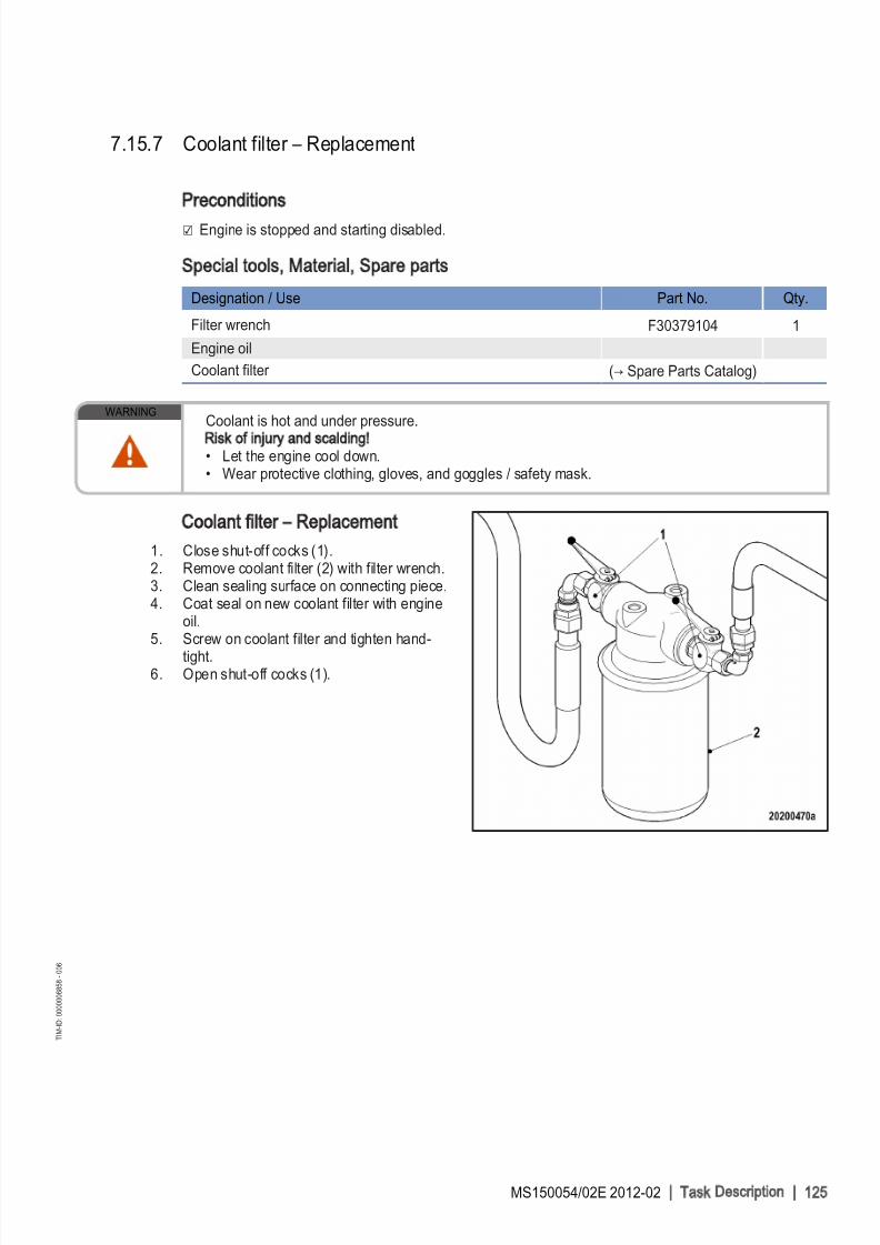
8/10/2019 MS150054_02E.pdf
http://slidepdf.com/reader/full/ms15005402epdf 125/155
7.15.7 Coolant filter – Replacement
Preconditions
☑ Engine is stopped and starting disabled.
Special tools, Material, Spare parts
Designation / Use Part No. Qty.
Filter wrench F30379104 1
Engine oil
Coolant filter (→ Spare Parts Catalog)
WARNINGCoolant is hot and under pressure.
Risk of injury and scalding
• Let the engine cool down.• Wear protective clothing, gloves, and goggles / safety mask.
Coolant filter – Replacement
1. Close shut-off cocks (1).2. Remove coolant filter (2) with filter wrench.3. Clean sealing surface on connecting piece.4. Coat seal on new coolant filter with engine
oil.5. Screw on coolant filter and tighten hand-
tight.6. Open shut-off cocks (1).
MS150054/02E 2012-02 | Task Description | 125
T I M - I D : 0 0 0 0 0 0 6 8 5 8 - 0 0 6

8/10/2019 MS150054_02E.pdf
http://slidepdf.com/reader/full/ms15005402epdf 126/155

8/10/2019 MS150054_02E.pdf
http://slidepdf.com/reader/full/ms15005402epdf 127/155
7.16.2 Charge-air coolant – Change
Special tools, Material, Spare parts
Designation / Use Part No. Qty.
Charge-air coolant
Charge-air coolant – Change
1. Drain charge-air coolant (→ Page 128).2. Fill with charge-air coolant (→ Page 129).
MS150054/02E 2012-02 | Task Description | 127
T I M - I D : 0 0 0 0 0 0 0 0 4 1 - 0 1 0

8/10/2019 MS150054_02E.pdf
http://slidepdf.com/reader/full/ms15005402epdf 128/155
7.16.3 Charge-air coolant – Draining
Preconditions
☑ Engine is stopped and starting disabled.
Special tools, Material, Spare parts
Designation / Use Part No. Qty.
Sealing ring (→ Spare Parts Catalog)
WARNINGCoolant is hot and under pressure.Risk of injury and scalding
• Let the engine cool down.
• Wear protective clothing, gloves, and goggles / safety mask.
Draining charge-air coolant
1. Provide an appropriate container to drainthe coolant into.
2. Turn breather valve of filler neck on coolantexpansion tank counterclockwise to firststop and allow pressure to escape.
3. Continue to turn breather valve counter‐clockwise and remove.
4. Draw off precipitated corrosion inhibitor oil
from the expansion tank through filler neck.5. Open drain valves and drain plugs anddrain coolant at the following points:• Charge-air coolant pump• Thermostat housing
6. Draining of residual coolant:• Intercooler
7. Close all drain valves and install drain plugswith new sealing rings.
8. Set breather valve onto filler neck and closeit.
128 | Task D escription | MS150054/02E 2012-02
T I M - I D : 0 0 0 0 0 1 4 8 5 5 - 0 0 1

8/10/2019 MS150054_02E.pdf
http://slidepdf.com/reader/full/ms15005402epdf 129/155
7.16.4 Charge-air coolant – Filling
Preconditions
☑ Engine is stopped and starting disabled.
☑ MTU Fluids and Lubricants Specifications (A001061/..) are available.
Special tools, Material, Spare parts
Designation / Use Part No. Qty.
Charge-air coolant
WARNINGCoolant is hot and under pressure.Risk of injury and scalding
• Let the engine cool down.• Wear protective clothing, gloves, and goggles / safety mask.
CAUTIONCold coolant in hot engine can cause thermal stress.Formation of cracks in components
• Fill / top up coolant only into cold engine.
Preparatory steps
1. Turn breather valve of filler neck on coolant
expansion tank counterclockwise to firststop and allow pressure to escape.2. Continue to turn breather valve counter‐
clockwise and remove.
MS150054/02E 2012-02 | Task Description | 129
T I M - I D : 0 0 0 0 0 1 4 8 4 8 - 0 0 2

8/10/2019 MS150054_02E.pdf
http://slidepdf.com/reader/full/ms15005402epdf 130/155
Filling with charge-air coolant using
pump
1. Connect a suitable pump with a hose to the
drain valve (arrow).
2. Release union at distributor (arrow).3. Open drain valve and pump coolant into en‐
gine at 0.5 bar minimum.4. Close venting point when coolant emerges
from the released union.5. Fill expansion tank until overflow edge is
reached.6. Close drain valve.7. Check proper condition of breather valve,
clean sealing faces if required.8. Set breather valve onto filler neck and close
it.9. Start engine (→ Page 32).
10. After the engine has run at unloaded condi‐tion for 10 seconds, stop engine(→ Page 35).
11. Turn breather valve of filler neck on coolantexpansion tank counterclockwise to firststop and allow pressure to escape.
12. Continue to turn breather valve counter‐clockwise and remove.
13. Check coolant level (→ Page 126) and topup if required:
a) Fill in coolant via filler neck on expan‐sion tank until the coolant level at bot‐tom edge of filler neck remains con‐stant.
b) Check proper condition of breather valve, clean sealing faces if required.
c) Fit breather valve and close.14. Repeat the steps from "Start engine"
(→ Step 8) until coolant is no longer neededto be topped up.
15. Disconnect pump and hose.
130 | Task D escription | MS150054/02E 2012-02
T I M - I D : 0 0 0 0 0 1 4 8 4 8 - 0 0 2

8/10/2019 MS150054_02E.pdf
http://slidepdf.com/reader/full/ms15005402epdf 131/155
Alternatively: Filling coolant
through filler neck
1. Open venting point at distributor (arrow).
2. Fill in coolant in expansion tank until thecoolant level at top edge of filler neck re‐mains constant.
3. Close venting point when coolant emerges.4. Check proper condition of breather valve,
clean sealing faces if required.5. Set breather valve onto filler neck and close
until first stop is reached.6. Start engine (→ Page 32).7. After the engine has run at unloaded condi‐
tion for 10 seconds, stop engine(→ Page 35).
8. Turn breather valve counterclockwise and
remove.9. Check coolant level (→ Page 126) and top
up if required:a) Repeat the steps from "Start engine"
(→ Step 6) until coolant is no longer needed to be topped up.
b) Check proper condition of breather valve, clean sealing faces if required.
c) Set breather valve onto filler neck andclose it.
Final steps
1. Start the engine and operate it at unloaded condition for some minutes.2. Check coolant level (→ Page 126) and top up if required.
MS150054/02E 2012-02 | Task Description | 131
T I M - I D : 0 0 0 0 0 1 4 8 4 8 - 0 0 2

8/10/2019 MS150054_02E.pdf
http://slidepdf.com/reader/full/ms15005402epdf 132/155

8/10/2019 MS150054_02E.pdf
http://slidepdf.com/reader/full/ms15005402epdf 133/155
7.17 Belt Drive
7.17.1 Drive belt – Condition check
Preconditions
☑ Engine is stopped and starting disabled.
☑ Guard is removed.
Drive belt – Condition check
Item Findings Action
Drive belt A Singular cracks None
Drive belt Belt is oily, shows signs of over‐heating
Replace(→ Page 136)
Drive belt B Cracks on entire circumference
Drive belt C Chunking
MS150054/02E 2012-02 | Task Description | 133
T I M - I D : 0 0 0 0 0 0 0 9 2 0 - 0 0 8

8/10/2019 MS150054_02E.pdf
http://slidepdf.com/reader/full/ms15005402epdf 134/155

8/10/2019 MS150054_02E.pdf
http://slidepdf.com/reader/full/ms15005402epdf 135/155
7.18.2 Battery-charging generator drive – Drive belt tension adjustment
Preconditions
☑ Engine is stopped and starting disabled.
Special tools, Material, Spare parts
Designation / Use Part No. Qty.
Torque wrench, 20-100 Nm F30026582 1
Ratchet adapter F30027340 1
WARNINGSpring/circlip/tensioning roller preload.Risk of injury
• Only use specified tool and equipment.
Adjusting belt tension
1. Undo screw (arrow) and remove protectivecover (3).
2. Slacken screws (1) and (2) by half a turn.Result: Belt tensioner moves against the drive belt
and tensions it.
3. Tighten screw (2) to specified torque using a torque wrench.
Name Size Type Lubricant Value/Standard
Screw M10x1.5 Tightening torque 60 Nm +5 Nm
4. Tighten screw (1) to specified torque using a torque wrench.
Name Size Type Lubricant Value/Standard
Screw M10x1.5 Tightening torque 42 Nm
5. Install protective cover (3).
MS150054/02E 2012-02 | Task Description | 135
T I M - I D : 0 0 0 0 0 0 7 3 8 6 - 0 0 2

8/10/2019 MS150054_02E.pdf
http://slidepdf.com/reader/full/ms15005402epdf 136/155
7.18.3 Battery-charging generator drive – Drive belt and belt tensioner replacement
Preconditions
☑ Engine is stopped and starting disabled.
Special tools, Material, Spare parts
Designation / Use Part No. Qty.
Torque wrench, 20-100 Nm F30026582 1
Ratchet adapter F30027340 1
WARNINGHeavy object.Risk of crushing
• Use appropriate lifting devices and appliances.
Replacing drive belt and belt
tensioner
1. Undo screws (1), (2) and (3).2. Remove protective cover (8).3. Slacken screws (4) and (5) by half a turn.4. Place socket adapter or box wrench on
screw (6) and press belt tensioner in the di‐rection indicated by the arrow as far as it
will go.5. Tighten screw (4).6. Remove drive belt (7).7. Screw on screw (5) and replace belt ten‐
sioner.8. Fit new drive belt (7).
Tensioning drive belt
1. Slacken screw (4) by half a turn.Result: Belt tensioner moves against the drive belt and tensions it.
2. Use torque wrench to tighten screw (4) to specified tightening torque.
Name Size Type Lubricant Value/Standard
Screw M10x1.5 Tightening torque 60 Nm +5 Nm
3. Use torque wrench to tighten screw (5) to specified tightening torque.
Name Size Type Lubricant Value/Standard
Screw M10x1.5 Tightening torque 42 Nm
4. Install protective cover (8).5. Readjust belt tension after 30 minutes and again after 8 hours engine runtime (→ Page 135).
136 | Task D escription | MS150054/02E 2012-02
T I M - I D : 0 0 0 0 0 0 7 4 2 1 - 0 0 4

8/10/2019 MS150054_02E.pdf
http://slidepdf.com/reader/full/ms15005402epdf 137/155
7.19 Fan Drive
7.19.1 Fan drive – Drive belt check / adjustment
Preconditions
☑ Engine is stopped and starting disabled.
Special tools, Material, Spare parts
Designation / Use Part No. Qty.
Optibell 2 belt tension tester Y4345711 1
Preparatory steps
1. Remove protective cover.2. Check belt condition visually (→ Page 133).
Result: For drive belt replacement, (→ Page 139).
Checking Vee belt tension
1. Switch on belt tension tester.2. Hold measuring tip of belt tension tester over belt drive. Tap drive belt (arrow) with a suitable tool.
3. Hold belt tension tester over belt drive until the measured value is indicated.
Initial operation with fan Belt tension adjustment
58 Hz ± 5 Hz 51 Hz ± 5 Hz
MS150054/02E 2012-02 | Task Description | 137
T I M - I D : 0 0 0 0 0 1 5 3 0 8 - 0 0 3

8/10/2019 MS150054_02E.pdf
http://slidepdf.com/reader/full/ms15005402epdf 138/155
Adjusting drive belt tension
1. Release screws (2) until fan coupling canbe moved.
2. Tighten stud (1) until the required frequencyis achieved.
3. Tighten screws (2) to 100 Nm ± 10 Nm.
138 | Task D escription | MS150054/02E 2012-02
T I M - I D : 0 0 0 0 0 1 5 3 0 8 - 0 0 3

8/10/2019 MS150054_02E.pdf
http://slidepdf.com/reader/full/ms15005402epdf 139/155
7.19.2 Fan drive – Drive belt replacement
Preconditions
☑ Engine is stopped and starting disabled.
Special tools, Material, Spare parts
Designation / Use Part No. Qty.
Drive belt (→ Spare Parts Catalog)
Preparatory steps
1. Remove protective cover.2. Remove fan.
Replacing drive belt
1. Release screws (2).2. Slacken off stud (1) until drive belt can be
removed.3. Clean belt pulleys.4. Fit new drive belt on belt pulleys, ensuring
that it is not under tension.5. Adjust belt tension (→ Page 137).
MS150054/02E 2012-02 | Task Description | 139
T I M - I D : 0 0 0 0 0 0 7 4 5 7 - 0 0 3
8/10/2019 MS150054_02E.pdf
http://slidepdf.com/reader/full/ms15005402epdf 140/155
7.20 Wiring (General) for Engine/Gearbox/Unit
7.20.1 Engine wiring – Check
Preconditions
☑ Engine is stopped and starting disabled.
Special tools, Material, Spare parts
Designation / Use Part No. Qty.
Isopropyl alcohol X00058037 1
Engine wiring – Check
1. Check securing screws of cable clamps on engine and tighten loose threaded connections.2. Ensure that cables are fixed in their clamps and cannot swing freely.3. Check that cable ties are firm, tighten loose cable ties.4. Replace faulty cable ties.5. Visually inspect the following electrical line components for damage:
• connector housings;• contacts;• sockets;• cables and terminals;• plug-in contacts.
6. (→ Contact Service) if cable conductors are damaged.
Note: Close male connectors that are not plugged in with the protective cap supplied.7. Clean dirty connector housings, sockets and contacts with isopropyl alcohol.8. Ensure that all sensor connectors are securely engaged.
140 | Task D escription | MS150054/02E 2012-02
T I M - I D : 0 0 0 0 0 0 0 0 2 9 - 0 1 7

8/10/2019 MS150054_02E.pdf
http://slidepdf.com/reader/full/ms15005402epdf 141/155
7.21 Accessories for (Electronic) Engine Governor / Control
System
7.21.1 Engine governor and connectors – Cleaning
Preconditions
☑ Engine is stopped and starting disabled.
Special tools, Material, Spare parts
Designation / Use Part No. Qty.
Isopropyl alcohol X00058037 1
Note: Always use test connectors to enter the connectors. Never use test leads for this purpose.Otherwise thecontacts could be bent.
Engine governor and connectors – Cleaning
1. Remove coarse dirt from housing surface with isopropyl alcohol.2. Remove dirt from connector and cable surfaces with isopropyl alcohol.3. Check legibility of cable labels. Clean or replace illegible labels.
Cleaning severely contaminated connectors on the engine governor
Note: Seal unused connectors with the supplied protective cap.1. Release the latch and pull off connectors.2. Clean connector housings, connector socket housings and all contacts with isopropyl alcohol.3. When connectors, sockets and all contacts are dry: Fit connectors and lock them.
MS150054/02E 2012-02 | Task Description | 141
T I M - I D : 0 0 0 0 0 0 0 0 4 7 - 0 0 9

8/10/2019 MS150054_02E.pdf
http://slidepdf.com/reader/full/ms15005402epdf 142/155
7.21.2 EMU and connectors – Cleaning
Preconditions
☑ Engine is stopped and starting disabled.
Special tools, Material, Spare parts
Designation / Use Part No. Qty.
Isopropyl alcohol
EMU and connectors – Cleaning
1. Remove coarse dirt from housing surface using a cloth moistened with isopropyl alcohol.2. Remove dirt from connector and cable surfaces with isopropyl alcohol.
3. Check legibility of cable labels. Clean or replace illegible labels.
Cleaning severely contaminated EMU connectors
1. Release latches of connectors and withdraw connectors.2. Clean connector housings, connector socket housings and all contacts with isopropyl alcohol.3. When connectors, sockets and all contacts are dry: Fit connectors and secure latches.
142 | Task D escription | MS150054/02E 2012-02
T I M - I D : 0 0 0 0 0 0 8 3 9 2 - 0 0 1

8/10/2019 MS150054_02E.pdf
http://slidepdf.com/reader/full/ms15005402epdf 143/155
7.21.3 Engine governor – Checking plug-in connections
Preconditions
☑ Engine is stopped and starting disabled.
Note: Always use test connectors to enter the connectors. Never use test leads for this purpose.Otherwise thecontacts could be bent.
Checking plug-in connections on engine governor
1. Check all plug-in connections for secure seating.2. Latch connectors if loose.
MS150054/02E 2012-02 | Task Description | 143
T I M - I D : 0 0 0 0 0 0 0 0 4 8 - 0 0 5
8/10/2019 MS150054_02E.pdf
http://slidepdf.com/reader/full/ms15005402epdf 144/155
7.21.4 EMU – Checking plug-in connections
Preconditions
☑ Engine is stopped and starting disabled.
EMU – checking plug-in connections
1. Verify that all plug-in connections are securely seated.2. Secure loose connectors and latch.
144 | Task D escription | MS150054/02E 2012-02
T I M - I D : 0 0 0 0 0 0 8 3 9 5 - 0 0 1

8/10/2019 MS150054_02E.pdf
http://slidepdf.com/reader/full/ms15005402epdf 145/155
7.21.5 ECU 7 engine governor – Removal and installation
Preconditions
☑ Engine is stopped and starting disabled.
CAUTIONWrong engine governor installed.Engine damage
• When reassembling an engine, make sure that the governor with the data record for the givenengine is installed.
Removing engine governor from
engine
1. Note or mark assignment of cables andconnectors.2. Remove all screws (2).3. Undo latches (3) of the connectors.4. Remove all connectors.5. Remove screws (1).6. Take off engine governor.
Installing engine governor on engine
1. Install in reverse order. In doing so, ensure correct assignment of connectors and sockets.2. Check rubber mount before installation.
Result: If the rubber mount is porous or defective, replace it.
MS150054/02E 2012-02 | Task Description | 145
T I M - I D : 0 0 0 0 0 0 0 0 4 9 - 0 0 5

8/10/2019 MS150054_02E.pdf
http://slidepdf.com/reader/full/ms15005402epdf 146/155
7.21.6 EMU 7 – Removal and installation
Preconditions
☑ Engine is stopped and starting disabled.
CAUTIONWrong engine governor installed.Engine damage
• When reassembling an engine, make sure that the governor with the data record for the givenengine is installed.
Removing ECU with EMU from
engine
1. Note or mark assignment of cables andconnectors.2. Remove all screws (2).3. Undo clips (3) on connectors.4. Disconnect all connectors.5. Remove screws (1).6. Remove ECU (1) with EMU (4).
Removing EMU
1. Undo screws on base of EMU (4).2. Remove EMU (4) from ECU (1).
Installing EMU
1. Place EMU (4) on ECU (1).2. Screw in and tighten screws on base of EMU (4).
Installing ECU with EMU on engine
1. Install in reverse order. Ensure correct assignment of connectors and sockets in so doing.2. Check resilient mount before installing.
Result: Replace resilient mount if porous or defective.
146 | Task D escription | MS150054/02E 2012-02
T I M - I D : 0 0 0 0 0 1 6 7 9 9 - 0 0 2

8/10/2019 MS150054_02E.pdf
http://slidepdf.com/reader/full/ms15005402epdf 147/155
8 Appendix A
8.1 Abbreviations
Abbreviation Meaning Explanation
A/D Analog/Digital Transformer: transforms sensor voltages intonumeric values
ADEC Advanced Diesel Engine Controller Engine management system
AFRS Air Filter Restriction Sensor
ANSI American National Standards Institute Association of American standardization or‐ganizations
ATL Abgasturbolader Exhaust turbocharger (ETC)ATS Air Temperature Sensor
BR Baureihe Series
BV Betriebsstoffvorschrift MTU Fluids and Lubricants Specifications,Publication No. A01061/..
CAN Controller Area Network Data bus system, bus standard
CDC Calibration Drift Compensation Setting of drift compensation in engine gov‐ernor with DiaSys
CEL Stop Engine Light 1st function: Warning lamp (rectify fault assoon as possible)
2nd function: Read out fault codes
CKT Circuit
CLS Coolant Level Sensor Monitors coolant level
CPS Coolant Pressure Sensor Monitors coolant pressure
CTS Coolant Temperature Sensor Monitors coolant temperature
DDEC Detroit Diesel Electronic Controls Engine control system made by Detroit Die‐sel
DDL Diagnostic Data Link Diagnostic lines
DDR Diagnostic Data Reader Diagnostic unit
DIN Deutsches Institut für Normung e. V. At the same time identifier of German stand‐ards (DIN = “Deutsche Industrie-Norm”)
DL Default Lost Alarm: Default CAN bus failure
DOC Diesel Oxidation Catalyst Oxidation catalyst upstream of the dieselparticulate filter
DPF Diesel Particulate Filter
DT Diagnostic Tool Diagnostic unit
ECM Electronic Control Module Electronic control unit of the DDEC system
ECU Engine Control Unit Engine governor
EDM Engine Data Module Memory module for engine dataEEPROM Electrically Erasable Programmable
Read Only Memory
EFPA Electronic Foot Pedal Assembly
MS150054/02E 2012-02 | Appendix A | 147
T I M - I D : 0 0 0 0 0 0 0 8 5 8 - 0 0 9

8/10/2019 MS150054_02E.pdf
http://slidepdf.com/reader/full/ms15005402epdf 148/155
Abbreviation Meaning Explanation
EGR Exhaust Gas Recirculation
EMU Engine Monitoring Unit
ETK Ersatzteilkatalog Spare Parts Catalog (SPC)EUI Electronic Unit Injector
FPS Fuel Pressure Sensor Monitors fuel pressure
FRS Fuel - Differential Pressure Sensor
FTS Fuel Temperature Sensor Monitors fuel temperature
FWCP Fire Water Control Panel Control cabinet
GND Ground
HD Hochdruck High Pressure (HP)
HI High Alarm: Measured value exceeds 1st maxi‐
mum limitHIHI High High Alarm: Measured value exceeds 2nd maxi‐
mum limit value
HT High Temperature
IDM Interface Data Module Memory module for interface data
INJ Injector
ISO International Organization for Stand‐ardization
International umbrella organization for all na‐tional standardization institutes
KGS Kraftgegenseite Engine free end in accordance with DIN ISO1204
KS Kraftseite Engine driving end in accordance with DINISO 1204
LED Light Emitting Diode
LO Low Alarm: Measured value lower than 1st mini‐mum limit value
LOLO Low Low Alarm: Measured value lower than 2nd mini‐mum limit value
LSG Limiting Speed Governor
N/A Not Applicable
LP Low Pressure
OEM Original Equipment Manufacturer
OI Optimized Idle
OLS Oil Level Sensor Monitors oil level
OPS Oil Pressure Sensor Monitors oil pressure
OTS Oil Temperature Sensor Monitors oil temperature
OT Oberer Totpunkt Top Dead Center (TDC)
PAN Panel Control panel
PIM Peripheral Interface Module
PWM Modulated signalP-xyz Pressure-xyz Pressure measuring point, xyz specifies the
measuring point designation
RL Redundancy Lost Alarm: Redundant CAN bus failure
148 | Appendix A | MS150054/02E 2012-02
T I M - I D : 0 0 0 0 0 0 0 8 5 8 - 0 0 9

8/10/2019 MS150054_02E.pdf
http://slidepdf.com/reader/full/ms15005402epdf 149/155
Abbreviation Meaning Explanation
SAE Society of Automotive Engineers U.S. standardization organization
SD Sensor Defect Alarm: Sensor failure
SEL Stop Engine Light 1st function: Warning lamp (stop engine andrectify fault)
2nd function: Read out fault codes
SID System Identifier
SRS Synchronous Reference Sensor TDC cylinder 1
SS Safety System Safety system alarm
TBS Turbocharger Boost Sensor Monitors charge-air pressure
TCI Turbo Compressor Inlet
TCO Turbo Compressor Outlet
TD Transmitter Deviation Alarm: Deviation in transmitter valuesTPS Throttle Position Sensor
TRS Timing Reference Sensor
T-xyz Temperature-xyz Temperature measuring point, xyz specifiesthe measuring point designation
UT Unterer Totpunkt Bottom Dead Center (BDC)
VNT Variable Nozzle Turbine
VSG Variable-Speed Governor
VSS Vehicle Speed Sensor
WZK Werkzeugkatalog Tool Catalog (TC)
MS150054/02E 2012-02 | Appendix A | 149
T I M - I D : 0 0 0 0 0 0 0 8 5 8 - 0 0 9

8/10/2019 MS150054_02E.pdf
http://slidepdf.com/reader/full/ms15005402epdf 150/155

8/10/2019 MS150054_02E.pdf
http://slidepdf.com/reader/full/ms15005402epdf 151/155

8/10/2019 MS150054_02E.pdf
http://slidepdf.com/reader/full/ms15005402epdf 152/155
Ratchet adapter
Part No.: F30027340
Qty.:
Used in:
1
7.3.1 Crankcase breather – Oil separator element replacement, diaphragm check andreplacement (→ Page 70)
Qty.:Used in:
17.18.2 Battery-charging generator drive – Drive belt tension adjustment (→ Page 135)
Qty.:Used in:
17.18.3 Battery-charging generator drive – Drive belt and belt tensioner replacement (→Page 136)
Ratchet adapter
Part No.: F30027341
Qty.:
Used in:
1
7.13.2 Engine oil – Change (→ Page 103)
Ratchet with extension
Part No.: F30006212
Qty.:Used in:
17.1.1 Engine – Barring manually (→ Page 63)
Rigid endoscope
Part No.: Y20097353
Qty.:Used in:
17.2.1 Cylinder liner – Endoscopic examination (→ Page 66)
Ring socket, 24 mm
Part No.: F30039526
Qty.:Used in:
17.4.2 Valve clearance – Check and adjustment (→ Page 73)
Torque wrench 6-50 Nm
Part No.: F30027336
Qty.:Used in:
17.14.4 Centrifugal oil filter – Cleaning and filter-sleeve replacement (→ Page 113)
Torque wrench, 0.5-5 Nm
Part No.: 0015384230
Qty.:Used in:
17.6.2 Injector – Removal and installation (→ Page 79)
Torque wrench, 10-60 Nm
Part No.: F30510423
Qty.:Used in: 11.4 Crankshaft transport locking device (→ Page 8)
152 | Appendix B | MS150054/02E 2012-02
D C L - I D : 0 0 0 0 0 1 5 7 7 2 - 0 0 1

8/10/2019 MS150054_02E.pdf
http://slidepdf.com/reader/full/ms15005402epdf 153/155
Torque wrench, 10-60 Nm
Part No.: F30452769
Qty.:
Used in:
1
7.6.2 Injector – Removal and installation (→ Page 79)
Torque wrench, 20-100 Nm
Part No.: F30026582
Qty.:Used in:
17.18.2 Battery-charging generator drive – Drive belt tension adjustment (→ Page 135)
Qty.:Used in:
17.18.3 Battery-charging generator drive – Drive belt and belt tensioner replacement (→Page 136)
Torque wrench, 40-200 Nm
Part No.: F30027337
Qty.:Used in:
17.13.2 Engine oil – Change (→ Page 103)
Torque wrench, 6-50 Nm
Part No.: F30027336
Qty.:Used in:
17.3.1 Crankcase breather – Oil separator element replacement, diaphragm check andreplacement (→ Page 70)
Torque wrench, 60-320 Nm
Part No.: F30047446
Qty.:Used in:
11.4 Crankshaft transport locking device (→ Page 8)
Qty.:Used in:
17.4.2 Valve clearance – Check and adjustment (→ Page 73)
Torque wrench, 60-320 Nm
Part No.: F30452768
Qty.:Used in:
17.6.2 Injector – Removal and installation (→ Page 79)
MS150054/02E 2012-02 | Appendix B | 153
D C L - I D : 0 0 0 0 0 1 5 7 7 2 - 0 0 1

8/10/2019 MS150054_02E.pdf
http://slidepdf.com/reader/full/ms15005402epdf 154/155

8/10/2019 MS150054_02E.pdf
http://slidepdf.com/reader/full/ms15005402epdf 155/155
F
Fan drive
– Drive belt check / adjustment 137
– Drive belt replacement 139
Fire prevention and environmental protection 16Firing order 28
Fluids and lubricants 16
Fuel
– Prefilter
– Flushing 89
Fuel filter
– Replacement 85
Fuel prefilter
– Differential pressure gauge
– Check and adjustment 87
– Draining 88
– Filter element
– Replacement 91
– Flushing 89
Fuel prefilter cleaning 86
Fuel system
– Venting 84
G
General conditions 5
H
HP pump
– Filling with engine oil 77
Putting the engine into operation after scheduled out-of-
service-period 31
R
Rubber sleeves between air intake elbow and turbo‐
charger
– Replacement 96
Rubber sleeves in air pipework before intercooler
– Replacement 99
S
Safety instructions 18
Sensors
– Overview 21
Service partners 150
Start engine in manual mode (testing mode) 32
Starting the engine in emergency situations (override
mode) 33Startup and operation
– Safety regulations 11
Stop engine in manual mode (testing mode) 35
T
Transport 7
Troubleshooting 40
V
Valve clearance
– Adjustment 73


