Embed Size (px)
Citation preview

University of Southern Queensland
Faculty of Health, Engineering and Sciences
miniROV
A dissertation submitted by
Mr Matthew Robe
In fulfilment of the requirements of
Bachelor of Engineering
Major in Mechatronics
October 2014
i
ABSTRACT
ROVs (Remotely Operable underwater Vehicle) are versatile vehicles used to get into
hard-to-reach and/or dangerous marine environments. Current ROVs are expensive and
require either a hardwire tether to the operator(s) or expensive acoustic communication
methods, both limiting the distance an operator (usually more than one) is from the ROV.
Given that underwater diving is a very dangerous profession, making up 27% of
Australia’s ocean and harbour deaths prior 2012/2013, there is an obvious need for an
affordable ROV which is wirelessly controllable by a single operator in a location remote
from the ROV, and which is capable of verbal and visual communication with divers, in
particular marine archaeologists.
In determining if such a ROV is possible, a comprehensive study of existing ROVs,
communication techniques, components/elements available, and costings were examined.
From this a system model of a buoy buddy system was developed. There are three main
elements to this model: a buoy, a ROV, and the operator. The buoy is hardwire tethered
to the ROV. The operator is then able to wirelessly communicate with the buoy through
traditional IP networks (i.e. GSM or WiFi networks).
It was concluded that the system model would be economically and physically feasible.
Further work is required to ascertain if this system model derived will become a reality.

ii
University of Southern Queensland
Faculty of Health, Engineering and Sciences
ENG4111/ENG4112 Research Project
LIMITATIONS OF USE
The Council of the University of Southern Queensland, its Faculty of Health, Engineering
& Sciences, and the staff of the University of Southern Queensland, do not accept any
responsibility for the truth, accuracy or completeness of material contained within or
associated with this dissertation.
Persons using all or any part of this material do so at their own risk, and not at the risk of
the Council of the University of Southern Queensland, its Faculty of Health, Engineering
& Sciences or the staff of the University of Southern Queensland.
This dissertation reports an educational exercise and has no purpose or validity beyond
this exercise. The sole purpose of the course pair entitled “Research Project” is to
contribute to the overall education within the student’s chosen degree program. This
document, the associated hardware, software, drawings, and other material set out in the
associated appendices should not be used for any other purpose: if they are so used, it is
entirely at the risk of the user.

iii
University of Southern Queensland
Faculty of Health, Engineering and Sciences
ENG4111/ENG4112 Research Project
CERTIFICATION OF DISSERTATION
I certify that the ideas, designs and experimental work, results, analyses and conclusions
set out in this dissertation are entirely my own effort, except where otherwise indicated
and acknowledged.
I further certify that the work is original and has not been previously submitted for
assessment in any other course or institution, except where specifically stated.
M. Robe
0061004798

iv
ACKNOWLEDGEMENTS
Firstly, I would like to thank my parents and brothers for their endless support and
encouragement. They are the foundation of who I am today.
I would also like to thank my supervisor, Dr Andrew Maxwell, and my long-time friend
Mr Andrew Bolous, for their guidance and contributions.

v
TABLE OF CONTENTS
ABSTRACT i
LIMITATIONS OF USE ii
CERTIFICATION OF DISSERTATION iii
ACKNOWLEDGEMENTS iv
List of Figures viii
List of Tables x
List of Appendices xi
Nomenclature and acronyms xii
List of Constants & Variables xiii
Chapter 1 INTRODUCTION 1
1.1 Outline of Study 1
1.2 Introduction 1
1.3 The Problem(s) 2
1.4 Research Objectives 2
1.5 Conclusions 3
Chapter 2 LITERATURE REVIEW 4
2.1 Introduction 4
2.2 SCUBA Diving & Marine Archaeology 4
2.3 What is a ROV? 7
2.4 Types of ROVs 7
2.4.1 Glider 7
2.4.2 Robotic 8
2.5 Previous Designs 9
2.5.1 Bluefin-21 9
2.5.2 Dive Works Work Class ROV 10
2.5.3 Hercules 11
2.5.4 Global Explorer 11
2.5.5 Sea Explorer 12
2.5.6 OpenROV 13
2.6 Conclusions 14
Chapter 3 METHODOLOGY 15
3.1 Introduction 15
3.2 Methods of Communication 15
3.3 Buoyancy & Stability 16
vi
3.4 Peer-to-peer underwater communication 18
3.5 Hydrodynamic Drag 19
3.6 Thrust 21
3.7 Hardware 21
3.7.1 Camera & Lighting 21
3.7.2 Inverters 23
3.7.3 Umbilical Cord (Tether) 23
3.7.4 Telemetry 24
3.7.5 Emergency Air Tank 25
3.7.6 Manipulator Arm 26
3.7.7 Motors 26
3.8 Control System 27
3.8.1 Depth control 27
3.8.2 Navigation 28
3.9 Conclusions 28
Chapter 4 SYSTEM DESIGN 29
4.1 Introduction 29
4.2 System Model 29
4.2.1 Chassis 31
4.2.2 Video Capture 31
4.2.3 Tether Management System 31
4.2.4 Propulsion 31
4.2.5 Control System 31
4.2.6 Telemetry 32
4.2.7 Variable Ballast System 32
4.2.8 Power 32
4.2.9 Diver Communications 32
4.3 Methods of Communication 33
4.3.1 Completely Wireless 33
4.3.2 Operator to buoy tether 33
4.3.3 ROV to buoy tether 35
4.4 Full System Overview 37
4.5 ROV Requirements 38
4.5.1 Structural Requirements 38
4.5.2 Electrical Requirements 38
4.5.3 Functional Requirements 39

vii
4.6 ROV Equipment 39
4.6.1 Frame Materials 39
4.6.2 Thrust & Motor Layout 41
4.6.3 Variable Ballast System 44
4.6.4 Camera, Telemetry and tether 46
4.6.5 Computer & Electronic Equipment 48
4.7 Final ROV Design 51
4.7.1 Structural Analysis 51
4.7.2 Components 53
4.7.3 Fluid Analysis 55
4.8 Buoy 59
4.8.1 Structural Requirements 59
4.8.2 Electronic Requirements 59
4.8.3 Functional Requirements 60
4.9 Buoy Equipment 60
4.9.1 Photovoltaic Panel(s) & battery bank 60
4.9.2 Electronic Components (GPS, Compass & Wireless transmission) 62
4.10 Final Buoy Design 64
4.10.1 Components 65
Chapter 5 CONCLUSIONS 66
5.1 Future Work 67
References 68
Appendices 71

viii
LIST OF FIGURES
Figure 2-1: Ocean / Harbour Drowning Deaths by Activity Immediately Prior, 2012/13
(Source: Denoble, et al., 2008).......................................................................................... 5
Figure 2-2: Cause of death in 814 DAN America scuba fatalities (not previously
published) (Source: Denoble, et al., 2008) ........................................................................ 6
Figure 2-3: Spectrum AUV glider (Source: MacNeill, 2008)........................................... 8
Figure 2-4: ROV Operators (Source: Kempin, 2010) ....................................................... 9
Figure 2-5: Bluefin-21 AUV (Source: BlueFin Robotics, 2014) ...................................... 9
Figure 2-6: DIVEworks Seaeye Leopard ROV (Source: DIVEworks, 2014) ................ 10
Figure 2-7: Hercules ROV by IFE (Source: NOAA, 2014) ............................................ 11
Figure 2-8: Sea Explorer AUV (Source: ACSA Alcen, 2014) ....................................... 12
Figure 2-9: OpenROV image (Source: OPENROV, 2014) ............................................ 13
Figure 3-1: TMS, System Design (Source: Tarmey, 2006) ............................................ 16
Figure 3-2: Centre of Buoyancy (CB) & Centre of Gravity (CM/CG) relationship (Source:
Cornerstone Robotics, 2014) ........................................................................................... 18
Figure 4-1: System Model Specifications (Source: Robe, 2014) .................................... 30
Figure 4-2: Buoy-Operator tether (Source: Robe, 2014) ................................................ 34
Figure 4-3: Buoy-ROV tether (Source: Robe, 2014) ...................................................... 35
Figure 4-4: Overall System component schematic (Source: Robe, 2014) ...................... 37
Figure 4-5: PVC & PMMA Max. Stress (Source: Robe, 2014)...................................... 40
Figure 4-6: Preliminary motor layout (Source: Robe, 2014) .......................................... 41
Figure 4-7: Final motor layout (Source: Robe, 2014) ..................................................... 42
Figure 4-8: Relative-to-motor thrust visual (Source: Robe, 2014) ................................. 42
Figure 4-9: Percentage of utilised motor (Source: Robe, 2014) ..................................... 43
Figure 4-10: Hobby King 1700kV Brushless motor (Source: Hobby King, 2014) ........ 44
Figure 4-11: High Sensitivity water level (Source: Emart, 2014) ................................. 45
Figure 4-12: MV75 Micro 12V Solenoid (Source: Irrigation Australia, 2014) .............. 45
Figure 4-13: Logitech HD Pro Webcam C920 (Source: Logitech, 2014) ...................... 46
Figure 4-14: Luminus SST-90 LED (Source: lck-led, 2014) .......................................... 46
Figure 4-15: 12VDC Power loss analysis (Source: Robe, 2013) .................................... 47
Figure 4-16: 12VDC vs. 240VAC Power loss over 100m (Source: Robe, 2014) .......... 47
Figure 4-17: Beaglebone Black (Source: elinux, 2014) .................................................. 48
Figure 4-18: Arduino MEGA (Source: Marian, 2014) ................................................... 49
Figure 4-19: Piezoresistive pressure sensor (Source: digi-key, 2014) ............................ 49
Figure 4-20: MinIMU-9 9DOF Gyro, Compass, Accelerometer (Source: Pololu, 2014)
......................................................................................................................................... 50

ix
Figure 4-21: Ocean Reef GSM G-Power communicator (Source: Ocean Reef, 2014) .. 50
Figure 4-22: Final ROV Design (Source: Robe, 2014)................................................... 52
Figure 4-23: ROV design highlighting balancing weight adjuster (Source: Robe, 2014)
......................................................................................................................................... 52
Figure 4-24: Sectional view of the motor assembly (Source: Robe, 2014) .................... 53
Figure 4-25: ANSYS CFX fully constrained ROV model (Source: Robe, 2014) .......... 55
Figure 4-26: Incredibly simplified version on the inventor model for ANSYS (Source:
Robe, 2014) ..................................................................................................................... 56
Figure 4-27: ANSYS Fluent simulation result with pathlines representing static pressure
(Pa) (Source: Robe, 2014) ............................................................................................... 57
Figure 4-28: Drag monitor inputted for drag force in the X-Y-Z vectors (Source: Robe,
2014) ............................................................................................................................... 58
Figure 4-29: Century Deep Cycle Gel battery (Source: Century Batteries, 2014) ......... 61
Figure 4-30: 62W Semi-flexible PV Panel (Source: Kulkyne Kampers, 2014) ............. 62
Figure 4-31: Samsung Galaxy Neo (Source: JB Hifi, 2014) .......................................... 62
Figure 4-32: TP-Link TL- WA5110G Hi Power Long Distance WiFi (Source: Stardot,
2014) ............................................................................................................................... 63

x
LIST OF TABLES
Table 2-1: Bluefin Specifications (BlueFin Robotics, 2014) .......................................... 10
Table 2-2: DIVEworks Seaeye Leopard Specifications (Source: DIVEworks, 2014) ... 11
Table 2-3: Global Explorer ROV Specifications (DEEP SEA SYSTEMS International,
2014) ............................................................................................................................... 11
Table 2-4: Sea Explorer AUV Specifications (Source: ACSA Alcen, 2014) ................. 12
Table 2-5: OpenROV Specifications .............................................................................. 14
Table 3-1: Formulae for simple geometric objects ......................................................... 17
Table 3-2: Projected Area of common, simple shapes (Source: Robe, 2014) ................ 20
Table 3-3: integral LED household lumen ratings (Source: integral LED, 2014) .......... 22
Table 4-1: MinIMU-9 9DOF measuring capabilities (Source: Pololu, 2014) ................ 50
Table 4-2: ROV component/element costs (Source: Robe, 2014) .................................. 53
Table 4-3: sea water properties at 10oC (Source: ITTC, Appendix C.5) ....................... 55
Table 4-4: Buoy component cost list (Source: Robe, 2014) ........................................... 65

xi
LIST OF APPENDICES
Appendix A Project Specification 71
Appendix B Table of Materials 72
Appendix C ROV Design 73
Appendix C.1 ROV preliminary designs 73
Appendix C.2 ROV Detailed Drawings 74
Appendix C.3 MIT Wax for waterproofing (pages 9-11) 77
Appendix C.4 ROV Buoyancy calculations using PTC MathCAD®. 80
Appendix C.5 Sea Water Properties 83
Appendix C.6 3D *.iges models to working simulations 83

xii
NOMENCLATURE AND ACRONYMS
The following abbreviations have been used throughout the text and bibliography: -
ROV Remotely Operated/Operable underwater Vehicle
AUV Autonomous Underwater Vehicle
SCUBA Self-Contained Underwater Breathing Apparatus
CM Centre of Mass
CB Centre of Buoyancy
HD High Definition
SD Standard Definition
TMS Tether Management System
AGE Arterial Gas Embolism
DAN Divers Alert Network
CFD Computational Fluid Dynamics
ESC Electronic Speed Controller
PVC Polyvinyl Chloride
PMMA Polymethyl Methacrylate
VBS Variable Ballast System
LED Light Emitting Diode
GPS Global Positioning System
IP Internet Protocol

xiii
LIST OF CONSTANTS & VARIABLES
𝑔 = 𝑔𝑟𝑎𝑣𝑖𝑡𝑦 = 9.81(𝑚𝑠−1)
𝐹𝐷 = 𝐷𝑟𝑎𝑔 𝐹𝑜𝑟𝑐𝑒(𝑁𝑚)
𝐶𝐷 = 𝐷𝑟𝑎𝑔 𝐶𝑜𝑒𝑓𝑓𝑖𝑐𝑖𝑒𝑛𝑡
𝜌 = 𝑑𝑒𝑛𝑠𝑖𝑡𝑦 𝑜𝑓 𝑙𝑖𝑞𝑢𝑖𝑑 (𝑘𝑔 𝑚2⁄ )
𝑣 = 𝑣𝑒𝑙𝑜𝑐𝑖𝑡𝑦 (𝑚𝑠−1)
𝐴𝑝 = 𝑃𝑟𝑜𝑗𝑒𝑐𝑡𝑒𝑑 𝐴𝑟𝑒𝑎 (𝑚2)
𝑇 = 𝑇ℎ𝑟𝑢𝑠𝑡 𝐹𝑜𝑟𝑐𝑒 (𝑁𝑚)
𝐷𝑝 = 𝐷𝑖𝑎𝑚𝑒𝑡𝑒𝑟 𝑜𝑓 𝑃𝑟𝑜𝑝𝑒𝑙𝑙𝑒𝑟 (𝑚)
∆𝑣 = 𝐶ℎ𝑎𝑛𝑔𝑒 𝑖𝑛 𝑣𝑒𝑙𝑜𝑐𝑖𝑡𝑦 (𝑚𝑠−1)
𝐶𝑆𝐴 = 𝐶𝑟𝑜𝑠𝑠 𝑆𝑒𝑐𝑡𝑖𝑜𝑛 𝐴𝑟𝑒𝑎 (𝑚𝑚2)
𝑃 = 𝑃𝑟𝑒𝑠𝑠𝑢𝑟𝑒 (𝑀𝑃𝑎)
ℎ𝑑 = 𝑚𝑎𝑥𝑖𝑚𝑢𝑚 𝑑𝑒𝑝𝑡ℎ 𝑜𝑓 𝑅𝑂𝑉 (𝑚)

1
CHAPTER 1
INTRODUCTION
1.1 Outline of Study
The need for an affordable ROV (Remotely Operable underwater Vehicle) which is
wirelessly controllable by a single operator in a location remote from the ROV, and which
is capable of verbal and visual communication with divers, in particular marine
archaeologists was identified from preliminary research detailed in Chapter 2.
Study in this area has never been undertaken by anyone at USQ.
The purpose and scope of this study is detailed in 1.4 Research Objectives.
1.2 Introduction
ROVs are versatile vehicles used to get into hard-to-reach or dangerous marine
environments. There are many different versions of ROVs in the marketplace at the
moment. They currently require either: a hardwired tether from the operator all the way
to the ROV, or expensive acoustic communication methods to communicate between the
operator (on a boat) and the ROV.
This study firstly looks at already implemented designs for industrial and hobbyist ROVs.
An Autonomous Underwater Vehicle (AUV) system like the Bluefin-21 (by Bluefin
Robotics) has cost tens of thousands of US dollars to produce and requires technology
that small organisations cannot afford.
These designs are then assessed to see what can be improved upon to achieve wireless
communication that is economically and physically viable so that an operator can
manually control the ROV from remote locations.
This study will also address the need for effective verbal and visual communication
between divers, more specifically marine archaeologists, and people above the surface of
the water.
The system model will be of a ROV which is capable of giving these features to divers
and operators at a reasonable cost (i.e. less than AUD $4 000).
2
1.3 The Problem(s)
As briefly outlined in Section 1.1, this study looks at two major problems relating to
ROVs and marine archaeology;
The first problem – marine archaeologists have no method of live verbal and visual
communication with people above the surface of the water.
The second problem – ROVs lack the ability to communicate wirelessly with an operator
on land or in various other remote locations. They are also very expensive devices.
The specific effects of the second problem, and which will be addressed in Chapter 3 and
Chapter 4, are;
Complications related to wireless transmission in the air and water.
Tether management options
1.4 Research Objectives
The research comprised of identifying the problems, trends and needs for marine
archaeologists and ROVs. The main research objectives were derived from the project
specification (Appendix A). They are:
Research into previous designs of ROVs
o Covered in Section 2.4 and 2.5
Factors related to designing a ROV.
o Covered in Chapter 3: METHODOLOGY and Section 4.2
Critically evaluate the subsystems used in the previous designs of ROVs
o Also covered in Chapter 3: METHODOLOGY. This is also critically
evaluated through Chapter 4 where elements of the ROV were chosen and
required critical evaluation.
Selection of appropriate methods of navigating (controlling) ROVs
o For this study, it is the research into a computer integrated system that is
capable of controlling and receiving data from an operator and correctly
conveying that data to the vehicle.

3
o The innovative new wireless control system is covered in Section 4.3.
Integration of electronic components with the mechanical.
o This objective is referring to the integration of the components into the
frame/compartments, essentially a system model.
This is covered in Chapter 4: SYSTEM DESIGN.
A research objective that was not previously covered in the project specifications was the
investigation into marine archaeologists. The primary focus of the old specifications only
involved the research into a ROV, on its own, the actual study encompasses more than
that. It has extended objectives to:
Include in the design a method of live communication with divers.
o This is to incorporate both verbal and visual aids for divers.
As time permits a prototype was to be constructed and tested. A yearlong study into this
field proved that manufacturing a prototype was not possible in such a short time-frame.
However, a thorough investigation into a feasibility study involving a complete system
design and model was done.
1.5 Conclusions
This dissertation aims to come up with an innovative system design for a wirelessly
controlled ROV capable of voice and video capture.
The research is expected to result in a system model which will specify possible elements
of design and components required to solve the problem outlined in 1.3.
A review of literature for this research will identify what the minimum components
required for the design to be beneficial to marine archaeology.
The outcomes of this study will be used for the design and development of a ROV capable
of video and audio capture over wireless transmission.
4
CHAPTER 2
LITERATURE REVIEW
2.1 Introduction
Chapter 2 covers the preliminary research into the areas of recreational SCUBA diving,
marine archaeology, and of currently manufactured ROVs. The benefits of a ROV for
marine archaeology will also be covered.
2.2 SCUBA Diving & Marine Archaeology
SCUBA diving is the act of submersing oneself completely underwater where the diver
uses a self-contained underwater breathing apparatus (SCUBA). This is different from
two other methods of diving, breath-hold and air pumping from the surface, as SCUBA
diving allows divers to have an extended diving time over breath-hold and are not limited
to the length of the tube supplied for air pumping. SCUBA divers require an air tank (for
breathing), buoyancy compensators (for making the diver neutrally buoyant at any depth),
a dive computer (for changing buoyancy depending on depth & air pressure in tank), dive
boots & fins (for propulsion), a mask & a snorkel, double regulators (for on demand
breathing), pressure and temperature gauges, and an emergency air regulator (safety in
case of primary regulator failure). Optionally, pairs of divers can take ultrasound
communicators which attach to their full-face masks for verbal communication.

5
Figure 2-1: Ocean / Harbour Drowning Deaths by Activity Immediately Prior, 2012/13 (Source: Denoble,
et al., 2008)
Diving, inclusive of SCUBA, snorkel and free diving, account for 27% of Australia’s
Ocean/Harbour deaths prior to 2012/2013 (Figure 2-1). The most common cause of death
for divers is drowning. This isn’t due to one singular item failing, it is better reflected as
a chain of actions done by the diver that cause the death. For example, the regulator may
start failing which causes the diver to panic and do an emergency ascent, leading to death.
Ascending too fast, or ascending while holding breath, can cause lung expansion due to
the extreme change in ratio of outside body pressure to lung pressure. The gas in the lungs
has to go somewhere, including: air between the lungs (mediastinal emphysema), air
underneath the skin (subcutaneous emphysema) and collapsed lung (pneumothorax). This
is referred to as an arterial gas embolism (AGE) (Denoble & Douglas, 2009). AGE is the
most common cause of death as it can lead to other causes, for example drowning.

6
Figure 2-2: Cause of death in 814 DAN America scuba fatalities (not previously published) (Source:
Denoble, et al., 2008)
The current known causes of death (triggers) pre 2008 are gas-supply problems (41%),
entrapment/entanglement (19%) and equipment issues (16%). These make up 76% of the
triggers. Emergency ascent (60%), insufficient breathing gas (20%) and buoyancy
problems (14%) made up 94% of all causes of death (Denoble, et al., 2008). The gas-
supply & equipment issues can be interrelated as triggers which cause panic, creating
previously mentioned causes of death. The addition of emergency air helps remove this
panic.
Marine archaeology is the application of archaeology underwater. Archaeology is the
investigation of the physical remains of material cultures found through artefacts,
structures, human remains or animal and plant remains. For marine archaeologists, this is
often in shallow depths (no more than 100m) where they investigate ship wreaks and the
oceans floor for evidence of historical events. The divers’ equipment is very similar to
that of recreational SCUBA divers, however they do require delicate excavation tools and
cameras.
The application of a ROV underwater with the divers would add another dimension for
non-divers. A ROV could transport small payloads including diver finds and safety
equipment for the divers. The ROV would also be able to stream live footage and chat
with the divers.

7
2.3 What is a ROV?
A ROV is a Remotely Operable Underwater Vehicle. They are abbreviated to ROV to
avoid confusion with remote control vehicles. Typically ROVs are operated through the
use of an umbilical cord which is tethered from the controller to the vehicle. Umbilical
cords are made of multiple collections of cables to send signals to and from the vehicle
as well as power. This includes receiving the video feed of what the vehicle is seeing to
the operator. On a large scale, umbilical cords are used to send power from the operators’
location to the vehicle. The operator controls the vehicle with the use of a computer or a
joystick controller from a boat (industrial) or the land (hobby).
ROVs have many different uses since they are capable of navigating into hard to reach
locations. They are not restricted (like divers are) to any shallow depth, and do not have
dive duration limitations that affect safety.
2.4 Types of ROVs
2.4.1 Glider
Gliders have very little mechanical movements, so they use less electricity. This allows
them to travel large distances sampling water content over several days, to weeks at a
time. They move by changing depth; once at the apex of the dive they sample water, then
return to the surface. At the surface they transmit their data onshore, then receive orders
for their next sample location. On board, gliders can be equipped with:
sensors for sampling the water for scientific purposes
gyroscopic compasses & accelerometers for stability & direction
batteries for running components
a pump for evacuating a floodable chamber
To change depth, the glider either fills a bladder with water or shifts a battery package to
the tip of the vehicle. Figure 2-3 shows a glider using a small hydraulic to shift the battery
pack to change the pitch. Obviously this glider wouldn’t be able to rise to the surface
without some assistance. To do this it empties the flooded chamber at the rear. This gives
it positive buoyancy and will cause it to rise.

8
To change direction, it can either rotate a battery pack to change side balance, or it can
use ailerons. Both actions roll the vehicle to change direction.
Figure 2-3: Spectrum AUV glider (Source: MacNeill, 2008)
These gliders are able to control their pitch and roll on the fly, but they are completely
unable to change their yaw.
2.4.2 Robotic
In the hobbyist market, the robotic ROVs are solely used for observing underwater. When
it comes to the industrial applications of these ROVs, they are designed to test and
manipulate objects underwater. Robotic ROVs are the most versatile of all the underwater
vehicles. This version of vehicle typically uses an organised set of 3 or 8 thrusters to
control the horizontal thrust and elevation. On board, they can have different tools for
manipulation, these include; grappling, welding, cutting, etc. These tools typically attach
to the manipulator arm(s).
9
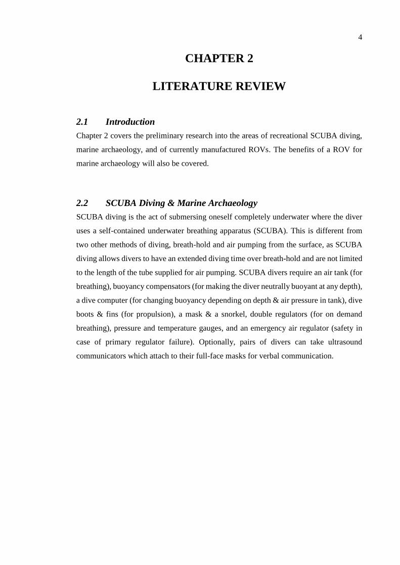
Figure 2-4: ROV Operators (Source: Kempin, 2010)
The number of operators required to control the vehicle can number 6; where 2 control
the cameras, 2 control the ROVs direction and the final 2 are there to do the delicate jobs
such as operating manipulator arms.
2.5 Previous Designs
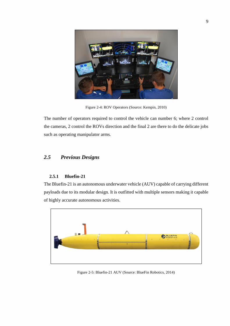
2.5.1 Bluefin-21
The Bluefin-21 is an autonomous underwater vehicle (AUV) capable of carrying different
payloads due to its modular design. It is outfitted with multiple sensors making it capable
of highly accurate autonomous activities.
Figure 2-5: Bluefin-21 AUV (Source: BlueFin Robotics, 2014)
10
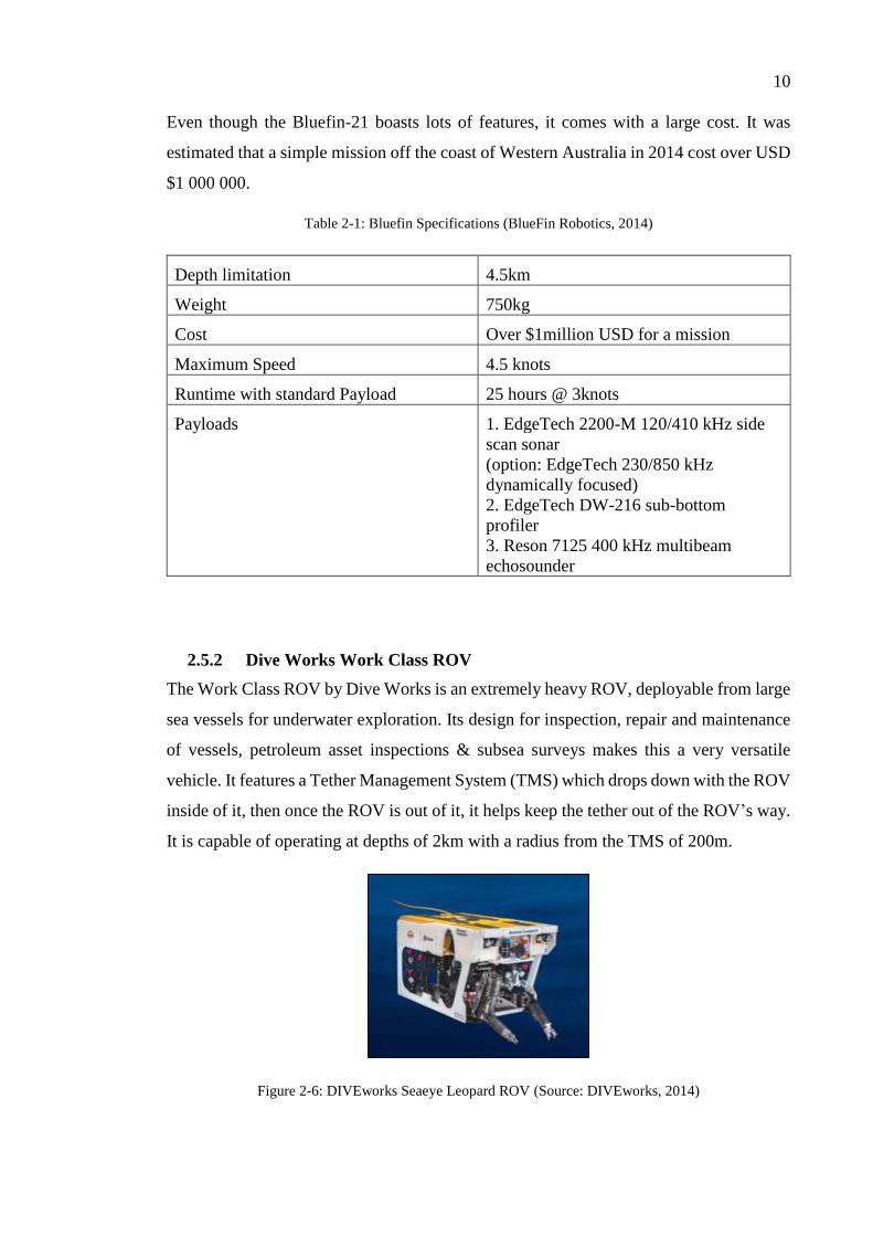
Even though the Bluefin-21 boasts lots of features, it comes with a large cost. It was
estimated that a simple mission off the coast of Western Australia in 2014 cost over USD
$1 000 000.
Table 2-1: Bluefin Specifications (BlueFin Robotics, 2014)
Depth limitation 4.5km
Weight 750kg
Cost Over $1million USD for a mission
Maximum Speed 4.5 knots
Runtime with standard Payload 25 hours @ 3knots
Payloads 1. EdgeTech 2200-M 120/410 kHz side
scan sonar
(option: EdgeTech 230/850 kHz
dynamically focused)
2. EdgeTech DW-216 sub-bottom
profiler
3. Reson 7125 400 kHz multibeam
echosounder
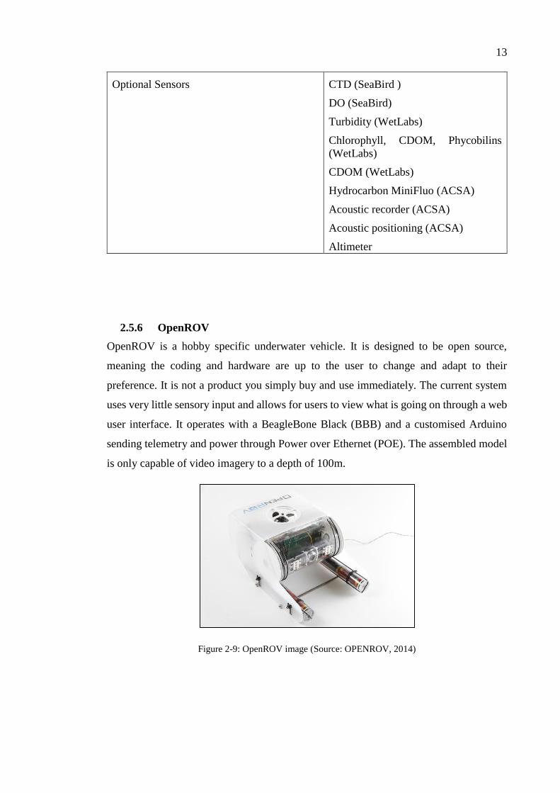
2.5.2 Dive Works Work Class ROV
The Work Class ROV by Dive Works is an extremely heavy ROV, deployable from large
sea vessels for underwater exploration. Its design for inspection, repair and maintenance
of vessels, petroleum asset inspections & subsea surveys makes this a very versatile
vehicle. It features a Tether Management System (TMS) which drops down with the ROV
inside of it, then once the ROV is out of it, it helps keep the tether out of the ROV’s way.
It is capable of operating at depths of 2km with a radius from the TMS of 200m.
Figure 2-6: DIVEworks Seaeye Leopard ROV (Source: DIVEworks, 2014)

11
Table 2-2: DIVEworks Seaeye Leopard Specifications (Source: DIVEworks, 2014)
Depth limitation 2.2km
Weight 3300kg
Payloads 1. Adjustable height garage to
accommodate ROV tool skids
2. up to 400kg extra for tooling/skid
2.5.3 Hercules
Built for the Institute for Exploration (IFE), Hercules is capable of performing delicate
tasks at a depth of 4km. Designed for study and recovering of artefacts from ancient
shipwrecks, this ROV has a High Definition (HD) camera for the intricate processes. To
reach the depths of 4km, Hercules goes down with its own TMS called Argus.
Figure 2-7: Hercules ROV by IFE (Source: NOAA, 2014)
2.5.4 Global Explorer
The Global Explorer is a portable ROV weighing approximately 13600kg able to be
transported in 40ft shipping containers or it can be side loaded onto a Boeing 737. The
ROV can be launched from a vessel with an A-Frame or an articulated crane. It features
the ability for 3D & HD video streaming through a fibre optic. Its most significant feature
is its large payload bay and manipulator arm. The manipulator arm is an Orion 7-function
spatially correspondent hydraulic manipulator. This manipulator arm is capable of
picking up objects, and is also outfitted with the capability to cut wire rope.
Table 2-3: Global Explorer ROV Specifications (DEEP SEA SYSTEMS International, 2014)

12
Depth limitation 3000m
Weight 14ton (30,000lb)
Payloads Up to 200lb (90kg) on the bay reduced
to 80lb (36kg) with the suction
sampler.
2.5.5 Sea Explorer
The Sea Explorer is the most advanced glider on the market. It dives by changing its
buoyancy and is capable of reaching speeds of 1 knot. It does not having moving wings
or any external moving objects. This reduces the risk of entanglement on debris and
makes it easier to launch. As it is an automated system, when it surfaces, it sends the GPS
location the pilot then dives again with the new GPS location specified.
Figure 2-8: Sea Explorer AUV (Source: ACSA Alcen, 2014)
Table 2-4: Sea Explorer AUV Specifications (Source: ACSA Alcen, 2014)
Depth limitation 700m
Weight 59kg
Maximum Speed 1 knot
Turn radius 20m
Runtime Up to 2 months
Payloads Two 9L wet/dry bays
13
Optional Sensors CTD (SeaBird )
DO (SeaBird)
Turbidity (WetLabs)
Chlorophyll, CDOM, Phycobilins
(WetLabs)
CDOM (WetLabs)
Hydrocarbon MiniFluo (ACSA)
Acoustic recorder (ACSA)
Acoustic positioning (ACSA)
Altimeter
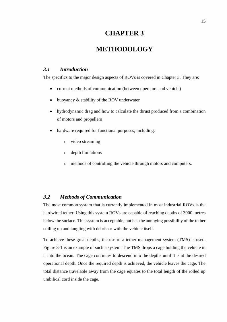
2.5.6 OpenROV
OpenROV is a hobby specific underwater vehicle. It is designed to be open source,
meaning the coding and hardware are up to the user to change and adapt to their
preference. It is not a product you simply buy and use immediately. The current system
uses very little sensory input and allows for users to view what is going on through a web
user interface. It operates with a BeagleBone Black (BBB) and a customised Arduino
sending telemetry and power through Power over Ethernet (POE). The assembled model
is only capable of video imagery to a depth of 100m.
Figure 2-9: OpenROV image (Source: OPENROV, 2014)

14
Table 2-5: OpenROV Specifications
Cost $849USD (KIT), $1450USD
(Assembled)
Depth limitation 100m
Weight N/A but is easy for a single person to
carry
Payloads Lithium batteries
2.6 Conclusions A ROV that is able to provide live verbal and visual communication with the divers and
operators above the surface of the water would be extremely beneficial. Currently, these
vehicles are extremely expensive. A more affordable alternative would be ideal,
especially if the system can be initiated and operated wirelessly from remote locations by
single operator. The details to designing a ROV is covered in Chapter 3.
15
CHAPTER 3
METHODOLOGY
3.1 Introduction
The specifics to the major design aspects of ROVs is covered in Chapter 3. They are:
current methods of communication (between operators and vehicle)
buoyancy & stability of the ROV underwater
hydrodynamic drag and how to calculate the thrust produced from a combination
of motors and propellers
hardware required for functional purposes, including:
o video streaming
o depth limitations
o methods of controlling the vehicle through motors and computers.
3.2 Methods of Communication
The most common system that is currently implemented in most industrial ROVs is the
hardwired tether. Using this system ROVs are capable of reaching depths of 3000 metres
below the surface. This system is acceptable, but has the annoying possibility of the tether
coiling up and tangling with debris or with the vehicle itself.
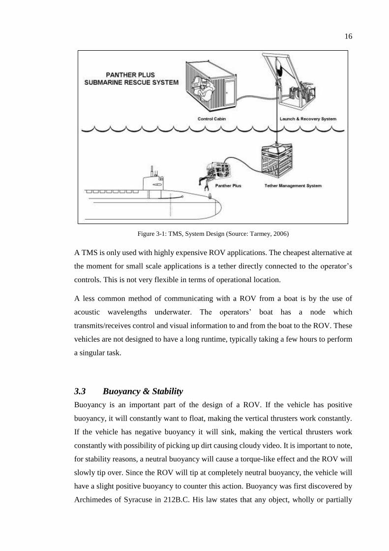
To achieve these great depths, the use of a tether management system (TMS) is used.
Figure 3-1 is an example of such a system. The TMS drops a cage holding the vehicle in
it into the ocean. The cage continues to descend into the depths until it is at the desired
operational depth. Once the required depth is achieved, the vehicle leaves the cage. The
total distance travelable away from the cage equates to the total length of the rolled up
umbilical cord inside the cage.
16
Figure 3-1: TMS, System Design (Source: Tarmey, 2006)
A TMS is only used with highly expensive ROV applications. The cheapest alternative at
the moment for small scale applications is a tether directly connected to the operator’s
controls. This is not very flexible in terms of operational location.
A less common method of communicating with a ROV from a boat is by the use of
acoustic wavelengths underwater. The operators’ boat has a node which
transmits/receives control and visual information to and from the boat to the ROV. These
vehicles are not designed to have a long runtime, typically taking a few hours to perform
a singular task.
3.3 Buoyancy & Stability
Buoyancy is an important part of the design of a ROV. If the vehicle has positive
buoyancy, it will constantly want to float, making the vertical thrusters work constantly.
If the vehicle has negative buoyancy it will sink, making the vertical thrusters work
constantly with possibility of picking up dirt causing cloudy video. It is important to note,
for stability reasons, a neutral buoyancy will cause a torque-like effect and the ROV will
slowly tip over. Since the ROV will tip at completely neutral buoyancy, the vehicle will
have a slight positive buoyancy to counter this action. Buoyancy was first discovered by
Archimedes of Syracuse in 212B.C. His law states that any object, wholly or partially

17
immersed in a fluid, is buoyed up be a force equal to the weight of the fluid displaced by
the object. This law can be used to derive a relationship between density and weight of
an object in a liquid.
𝑑𝑒𝑛𝑠𝑖𝑡𝑦 𝑜𝑓 𝑜𝑏𝑗𝑒𝑐𝑡
𝑑𝑒𝑛𝑠𝑖𝑡𝑦 𝑜𝑓 𝑓𝑙𝑢𝑖𝑑=
𝑤𝑒𝑖𝑔ℎ𝑡
𝑤𝑒𝑖𝑔ℎ𝑡 − 𝑎𝑝𝑝𝑎𝑟𝑒𝑛𝑡 𝑖𝑚𝑚𝑒𝑟𝑠𝑒𝑑 𝑤𝑒𝑖𝑔ℎ𝑡 (3.1)
For each element in the design, the buoyancy will be determined. This involves
calculating the volume of each solid and liquid to be submersed, multiplying it by the
density which will give a weight. Materials which are of higher density than sea water
will sink, the opposite will give buoyancy. The formulae for typical volumes of simple
shaped objects relating to this study can be seen in Table 3-1.
Table 3-1: Formulae for simple geometric objects
Type of 3D Shape Formulae for Volume
Cube 𝑉 = 3𝑙
Rectangular Prism 𝑉 = 𝑊 ∗ 𝐷 ∗ 𝑙
Cylinder (Solid) 𝑉 = 𝜋𝑟2. 𝑙
The weight of a solid is subtracted from the liquid to give the buoyancy as shown in
equation 3.2.
𝐵𝑢𝑜𝑦𝑎𝑛𝑐𝑦 𝑜𝑓 𝑒𝑙𝑒𝑚𝑒𝑛𝑡 = 𝑊𝑠𝑢𝑏𝑚𝑒𝑟𝑠𝑒𝑑 𝑠𝑜𝑙𝑖𝑑 − 𝑊𝑠𝑢𝑏𝑚𝑒𝑟𝑠𝑒𝑑 𝑓𝑙𝑢𝑖𝑑 (3.2)
If the value from equation 3.2 is negative, the vessel will sink, the opposite will happen
if this value is positive.
It will be necessary for the elements of the ROV to be buoyancy tested in order to
determine the required ballast. Since there are many elements to the vehicle, these
calculations will be done through PTC MathCAD®. The results for final design using
MathCAD® are in 0.
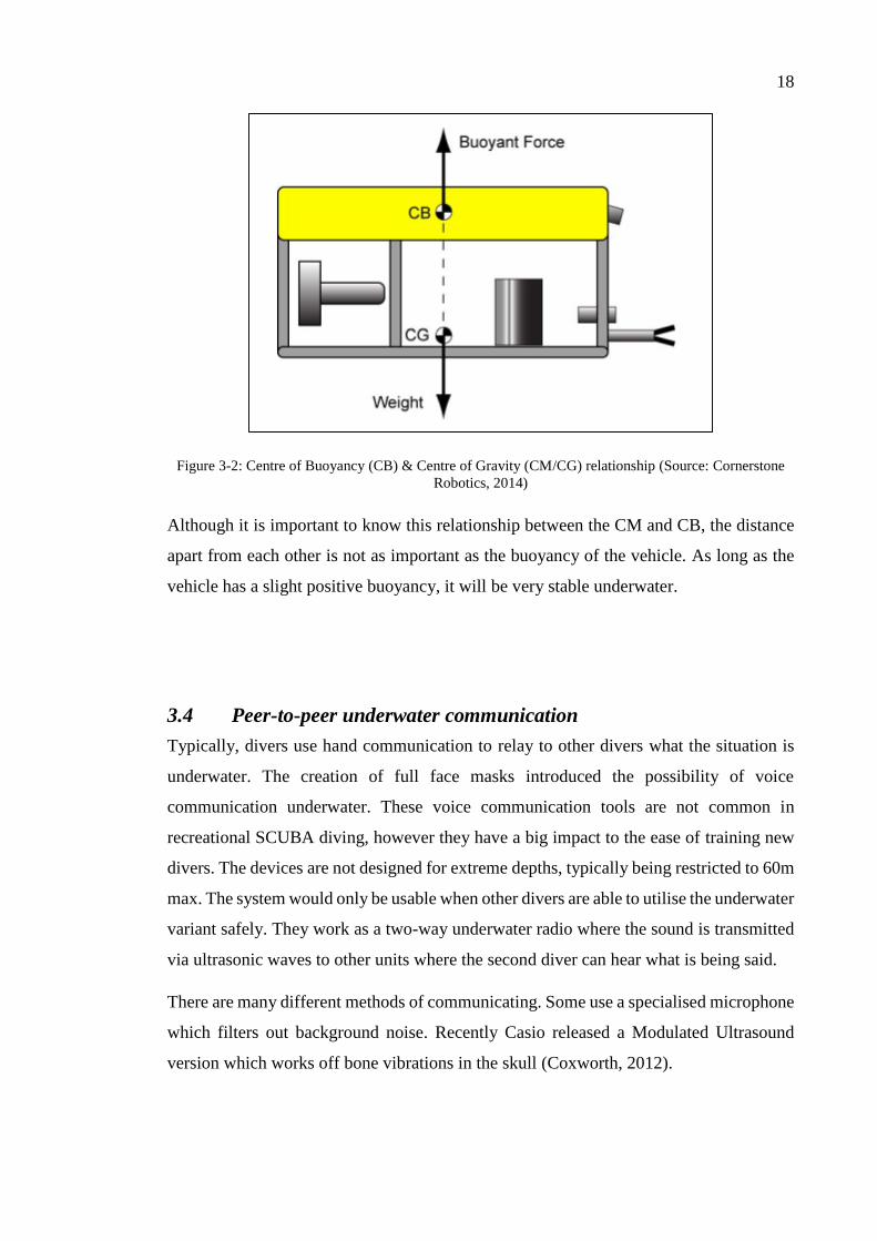
Underwater, a ROV acts like a damped pendulum. Thus, for best stability, the centre of
buoyancy (CB) and centre of mass/gravity (CM) have to be located apart with the CB
above the CM (See Figure 3-2). This will mean the ROV will be more stable the further
the distance between the CM and CB.
18
Figure 3-2: Centre of Buoyancy (CB) & Centre of Gravity (CM/CG) relationship (Source: Cornerstone
Robotics, 2014)
Although it is important to know this relationship between the CM and CB, the distance
apart from each other is not as important as the buoyancy of the vehicle. As long as the
vehicle has a slight positive buoyancy, it will be very stable underwater.
3.4 Peer-to-peer underwater communication
Typically, divers use hand communication to relay to other divers what the situation is
underwater. The creation of full face masks introduced the possibility of voice
communication underwater. These voice communication tools are not common in
recreational SCUBA diving, however they have a big impact to the ease of training new
divers. The devices are not designed for extreme depths, typically being restricted to 60m
max. The system would only be usable when other divers are able to utilise the underwater
variant safely. They work as a two-way underwater radio where the sound is transmitted
via ultrasonic waves to other units where the second diver can hear what is being said.
There are many different methods of communicating. Some use a specialised microphone
which filters out background noise. Recently Casio released a Modulated Ultrasound
version which works off bone vibrations in the skull (Coxworth, 2012).

19
3.5 Hydrodynamic Drag
The natural force on an object which resists its motion through a fluid (air or water) is
called drag. As the ROV is an underwater object, this drag is called hydrodynamic drag.
The portion of drag which is of importance is the pressure drag. Pressure drag is the inertia
of the fluid causing resistance which is required to be pushed aside.
Bernoulli’s equation for the pressure in a fluid is…
𝑃1 + 𝜌𝑔𝑦1 +1
2𝜌𝑣1
2 = 𝑃2 + 𝜌𝑔𝑦2 +1
2𝜌𝑣2
2
The part of this equation relevant to the drag of an object is the kinematic contribution of
the pressure of the fluid.
As pressure is a unit of the force applied over an area, we can solve the equation for
pressure to find the drag force.
𝑃 = 𝐹𝐴
𝐹𝐷 = 𝑃𝐴 =1
2𝜌𝑣2𝐴𝑝
As drag is influenced by many other factors; shape, texture, viscosity, lift, etc. These
factors can be neatened to one simple term called the drag coefficient (CD).
This leaves us with the equation for the drag force (FD N) (NASA, 2014):
𝐹𝐷 = 𝐶𝐷
1
2𝜌𝑣2𝐴𝑝 (3.3)
Where 𝐶𝐷 is the coefficient of drag on the object (no units)
𝜌 is the density of the fluid in kilograms per cubic metre (𝑘𝑔. 𝑚−3)
𝑣 is the flow of the water in metres per second (𝑚. 𝑠−1)
𝐴𝑃 is the projected area of the objects in (𝑚2)
The drag coefficient for simple objects is easily accessible through textbooks. This is a
different situation for odd shaped objects. ANSYS CFD (Computational Fluid Dynamics)
is a program that removes the problematic method of solving for the drag force of an
object. ANSYS will be used for the design to inspect the fluid dynamics of the model, to
help improve the design for optimised sizing. The value for the Drag Force can be used

20
in conjunction with the thrust calculations in section 0 which will be used to solve for an
estimated diameter for the propellers to achieve the required thrust.
The projected area 𝐴𝑝 for the calculation is the two-dimensional area under the effect of
the drag force. For simple shapes used in this study, refer to Table 3-2.
Table 3-2: Projected Area of common, simple shapes (Source: Robe, 2014)
Name of Shape Formula for Projected Area (AP)
Sphere 𝐴𝑃 = 𝜋. 𝑟2
Cube 𝐴𝑃 = 𝑙2
Rectangular Prism 𝐴𝑃 = 𝑙. 𝑤
Cylinder End 𝐴𝑃 = 𝜋. 𝑟2
Cylinder Wall 𝐴𝑃 = 𝑙. 𝐷
NOTE: These formulae are for the shapes at a normal perpendicular angle (90𝑜) with the plane of impact
of the drag force(𝐹𝐷).
Where 𝑙 is the length of the object in metres (m)
𝑟 is the radius of the object in metres (m)
𝑤 is the width of the object in metres (m)
𝐷 is the diameter of the object in metres (m)

21
3.6 Thrust
Thrust is the amount of force produced by a propeller relative to the flow & density of
the liquid. Often, the possible thrust capable for a propeller is given by the manufacturers
with relevance to the revolutions of the motor it is attached to. Unfortunately, the supplier
of the propellers available for the scale vehicle this study is going to model do not supply
relevant data. The best option for the thrust to be found would be purchasing of multiple
propellers & motors, then run the motor at 12V to find the optimal setup. This procedure
tests the motor’s current draw at a specific speed and the thrust produced by the propeller.
This test can be done in the future when the design is ready for prototyping.
The thrust output (T [N]) from the combination of the motors and propeller can be
identified in the equation below.
𝑇 =π
4𝐷𝑝
2 (𝑣 +∆𝑣
2) 𝜌∆𝑣 (3.4)
Where 𝑇 is the thrust in Newtons (𝑁)
𝐷𝑃 is the diameter of the propeller in metre/s (𝑚)
𝑣 is the velocity of incoming flow in metres per second (𝑚. 𝑠−1)
∆𝑣 is the additional velocity/acceleration by propeller in metres per sec (𝑚. 𝑠−1)
𝜌 is the density of the liquid in kilograms per cubic metre (𝑘𝑔/𝑚3)
3.7 Hardware
3.7.1 Camera & Lighting
For manual control, a live visual feed of where the ROV is going is essential for proper
navigation. Video cameras take multiple images and layer them to create a moving image.
The number of images/frame per second is referred to as the frame rate. The higher the
frames per second (FPS), the smoother the image will be. As the video is produced by
multiple images, there is often a fairly high bandwidth related to high definition (HD)
video.

22
There are currently three common resolutions for video capture: standard definition (SD)
has a pixel density of 720 x 480 pixels, and high definition (HD) has 1280 x 720 and 1920
x 1080 pixel options.
The bandwidth for these cameras varies, ranging from as low as 1Mbps to over 10Mbps
running with full 30FPS (perfect stream, low quality).
Ultra bright lighting will be required for the system model. Lumens is the measurement
for the total amount of visible (to the human eye) light from a light source (integral LED,
2014). The general ratings for a household lighting is shown in Table 3-3. For lighting
underwater (a task set objective) a luminosity of 800 lumens will be required. The most
energy efficient light producing product is an LED (Light Emitting Diode). A LED with
a power rating of 12W is capable of 806Lm of light, the equivalent of a 60W incandescent
bulb (rated at 850Lm). They are frequently available for an inexpensive cost and are also
available pre-made as singular high powered LEDs or as an array of multiple LEDs. It is
necessary to keep to the voltage within the manufacturer product requirements.
Table 3-3: integral LED household lumen ratings (Source: integral LED, 2014)

23
3.7.2 Inverters
Inverters are used as a device to change DC to AC voltage, and vice versa. Fortunately
these are very easy to acquire for the common Australian voltages of 12V and 240V. If
the battery bank on the buoy is set to 12VDC, high amperage, it can be scaled up to
240VAC by the inverter to be sent down the power supply lines to the ROV. Like on the
surface, this process can occur again on the ROV, transforming the power from 240VAC
to 12VDC to operate all the required components on the ROV. Prices of inverters vary
from AUD ~$30 to over AUD $600 through Jaycar Electronics. The cost of these will be
dependent on the amperage draw of the ROV components and the total length of the tether
investigated in Section 3.7.3.
3.7.3 Umbilical Cord (Tether)
The umbilical cord, also referred to as the tether, is the item that transmits data and power
from the surface of the water to the ROV. It is crucial that communication between the
buoy, on the surface, and the ROV, underwater, be consistent and capable of transmitting
all the data from the ROV to the buoy 24/7. There are two options for this are: to use
Power over Ethernet (POE) or a high speed Ethernet cable (CAT5E) with separate power
supply. The one major benefit of using POE is that data is transmitted through only two
cables. This benefits the design by making the tether lighter and more buoyant, keeping
it away from the ROV naturally. It also reduces the cost of increasing the buoyancy of
the tether and is easier than going with the other option (CAT5E).
Deducing when the use of AC over DC power transmission is an important factor for the
tether. The loss of any power over a distance is reliant on the impedance (𝑅) of the chosen
cable over the required distance. Ohm’s law is the basis for calculating the power loss
over the specified distance.
𝑃𝑙𝑜𝑠𝑠 = 𝐼2. 𝑅 (3.5)
Where 𝑃 is the power at the lost in watts (𝑊)
𝐼 is the current transmitted down the line in amperes (𝐴)
𝑅 is the impedance of the line over the required distance in ohms (Ω)
The impedance (𝑅) varies depending on the gauge of wire chosen. This has been
investigated in Section 0.

24
3.7.4 Telemetry
Telemetry is the automated transmission of measured data sent from a remote location
(ROV) to a receiver (Operator) for monitoring and storage. The word telemetry comes
from the Greek “Tele” meaning remote and “Metron” meaning measure. Telemetry is a
wireless data transfer between transmitter and receiver, the most common being through
GSM Networks (Global System for Mobile Communication) by using SMS (Short
Message Service) to send and receive data. Telemetry can also be referred to in computer
networking & telecommunications.
This section covers all relevant telemetry data/sensors available for ROVs.
GPS
Global Position System (GPS) consists of a network of multiple satellites (24 to 32 solar-
powered satellites) orbiting Earth at an altitude of approximately 20,000km, with control
stations on Earth located at Hawaii, Kawajale, Diego Garcia & Ascension Islands, and a
receiver (MiTAC International, 2014). The GPS receivers are commonly mobile phones,
GPS trackers, and GPS Navigation devices.
The control stations are used to monitor the satellites’ conditions. They initialise a
sequence to triangulate the position of the receiver from three of those satellites, then they
proceed to check the result against a fourth satellite. If the check procedure does not give
conclusive results, the process is repeated again until a precise location is found. The
measurement is done by timing the duration it takes for the microwave signals to travel
from the satellites to the receiver.
A GPS would be a worthwhile addition to a ROV if it is to be autonomous. This would
allow the possibility of adding waypoints for the ROV, like currently done with drones.
Depth
The best method to measure the depth a ROV will be located under the water’s surface is
with the use of a pressure gauge. This can be measured using four different collector
types: a Piezoresistive strain gauge (most common), Capacitive, electromagnetic,
Piezoelectric, Optical and Potentiometric. All methods excluding the Potentiometric &
Optical collectors detect the strain applied to a diaphragm. The last method is less

25
common and observes a change in wiper location (Potentiometric) or observes the
physical change in an optical fibre to detect strain (Optical). Essentially all collectors are
strain gauges that determine the actual pressure applied to a surface. This pressure can be
used to solve for the depth relative to atmospheric pressure.
Another option for depth measurement is by measuring the altitude above the sea floor.
Sonar Altimeters are one such measuring device. They use sonar wave frequencies and
their rebound time to calculate the distance off the ocean floor. There are many options
of Sonar Altimeters available but are all of high cost ~ USD $1000 (Kongsberg, 2014).
Accelerometer vs Gyroscope
A Gyroscope is capable of measuring the poll, roll and yaw of a vehicle, irrespective of
compass orientation (Goodrich, 2013). The device is used to maintain orientation based
on the principles of angular momentum. An Accelerometer measures the instantaneous
changes in velocity in any direction in proper acceleration called g-force (Dimension
Engineering LLC, 2014).
Since a ROV has very slow movements and is designed to be very stable, the use of a
gyroscope and accelerometer is somewhat unnecessary for the ROV in this system design.
The application of a 6DOF (Six Degrees of Freedom) is relatively cheap when using
electromechanical versions of these with prices ranging from AUD $2 to AUD $15.
Sensors
CTD (Conductivity, Temperature & Depth) sensors can be used to measure the salinity,
temperature and depth by means of conductivity in sea water. The pressure on the gauge
can give depth. The temperature and the salinity is measured by changes in the current
produced by the device due to the salinity in the water.
3.7.5 Emergency Air Tank
As this ROV will be used to communicate and navigate near other divers, a viable payload
could be the addition of emergency air (Kendig, 2007). This extra air availability would
help save lives in emergencies where a diver may panic or their regulator may start to
malfunction.

26
Spare Air is one such solution to this problem. Invented in 1986, Spare Air now has three
different options for tank sizes (Spare Air, 2014). With a capacity range from 48L (Model
170) to 85L (Model 300), Spare Air allows divers to get in 30 to 57 emergency breaths
(based on 1.6L per breath). This allows divers to safely make it to the surface of the water.
3.7.6 Manipulator Arm
Manipulator arms are relatively common amongst robotic ROVs. Typically being a 2 or
3 axis device, they are used by the larger ROVs to sample materials or remove/repair
material to gain access to new areas. Some optional functions of these arms are:
Gripping objects
Wire/Rope cutting
Wire brush
Welding
For the purposes of this project, the addition of a manipulator arm would not be included
unless specified by a client.
3.7.7 Motors
Primarily there are DC motors, Asynchronous and Synchronous AC motors. The major
differences between the DC and AC versions of motors is that DC motors require brushes
to make contact for them to work. These wear over time and cause DC motors to be less
efficient than AC motors.
There are a couple advantages of using AC motors over DC motors; no brushes required
& no commutator. Quite simply, AC motors are essentially a magnet inside which spins
instead of a coil (DC) (Wolfe, n.d.). These are generally more expensive than standard
DC motors, but the benefits significantly outweigh the minor increase in cost. This is
evident over time as they do not require any maintenance (except maybe the bearings).
Electronic Speed Controllers (ESC) are a basic requirement for brushless motors, as they
convert DC power to AC, allowing them to run. ESCs come in a variety of options ranging
from 5A to 200A. The cheaper ESCs do not have the capability of forward and reverse

27
control – they only have one direction. As the motors on a ROV are required to have
bidirectional control, these cheap ESCs do not meet the required specifications.
3.8 Control System
3.8.1 Depth control
Adjusting the depth of the vehicle can be done in two different ways: changing buoyancy
or using thrust produced by vertically aimed thrusters. As discussed in Section 3.3, the
buoyancy of a system is very important for the stability of the system underwater. A
negative buoyancy (required to sink the vehicle) will result in instability, which isn’t
desired. Mechanical adjustment of the ROV with vertically displaced thrust is the best
method of changing the depth when under live operation.
The ROV will need to withstand the pressure that results from the depth at which it is
required to operate in sea water. This can be expressed in the following formula…
𝑃 = 𝜌𝑔ℎ𝑑 (3.6)
Where 𝑃 is the pressure in Pascals (Pa)
𝜌 is the density of the fluid in kilograms per cubic metre (𝑘𝑔/𝑚3)
𝑔 is the acceleration due to gravity which is 9.81 metres per second (9.81𝑚/𝑠)
ℎ𝑑 is the maximum depth in metres (m)
Assuming the maximum length of the tether is 100m (without loss), and the density of
sea water is 1025 𝑘𝑔/𝑚3, the maximum pressure the ROV will need to withstand is:
𝑃 = 1025 ∗ 9.81 ∗ 100 = 1005525𝑃𝑎 𝑜𝑟 1.01𝑀𝑃𝑎
28
3.8.2 Navigation
Navigation of the ROV will primarily be manual (controlled by an operator). For the
operator to understand the ROV’s orientation and location, the computer system requires
a gyroscope, compass and depth gauge. There are multiple devices that can accept these
tools. These devices are Linux based computers, Arduino boards and BeagleBone Blacks.
The data processed by these computers can be sent over a hardwired network device
(Ethernet) or wirelessly (acoustic or traditional IP networks).
3.9 Conclusions
An affordable version of a ROV is possible if only the absolutely necessary components
for full functionality are used. The motor and propeller combination is outside the scope
of this project. Tests done in laboratory conditions will need to be completed to decide
on these components.
Since the ROV will be around a diver most of the time, a payload of emergency air and
ultrasonic communication services will be required in the system design.

29
CHAPTER 4
SYSTEM DESIGN
4.1 Introduction
Chapter 4 encompasses the design process (Section 4.2) required to achieve the
specifications detailed in Section 1.4.
The requirements and components of the ROV are chosen in Section 4.6, which dictates
the final design, depicted in Section 4.7.
The same process is covered for the buoy where the requirements and components are
selected in Section 4.8. The final design of the buoy is not required for this study, but an
example is given in Section 4.10.
4.2 System Model
A system model that encompasses the design requirements of the ROV has been
addressed. This model (Figure 4-1) has nine major areas that need addressing in the design
process. They are addressed in sections 4.2.1 to 4.2.9. Another major factor to take into
consideration is cost. The whole system should not exceed AUD ~$4000 for it to be
feasible; the complete system cost is in Chapter 5.

30
Figure 4-1: System Model Specifications (Source: Robe, 2014)

31
4.2.1 Chassis
The chassis of the ROV will be required to withstand all pressures up to and including a
depth of 100 metres below the surface of the water. This minimum pressure requirement
has been calculated in Section 4.6.1 to be 1.3MPa. This is a different situation for the
buoy, where there is no pressure exerted on its body. Both chassis requirements are
discussed in Sections 4.5.1 and 4.8.1 for the ROV and buoy, respectively.
The ROV will have an extra payload for the emergency air, previously discussed in
Section 3.7.5.
4.2.2 Video Capture
Video capture will only occur on the ROV and this will have to be of a high clarity,
allowing for clearer live footage. The choices made for the video feed have been discussed
in Section 4.6.4
4.2.3 Tether Management System
The TMS, from this point on in the report, will be referring to the method of tethering the
devices together for means of communication. The two feasible options for this are
discussed in Section 4.3 and the tether is discussed in Section 4.6.4.
4.2.4 Propulsion
Propulsion is the design subcategory that includes the motor and propeller combination.
This combination is required to provide two times thrust necessary to overcome the drag
coefficient of the ROV. As discussed in Section 3.6, this combination will be optimised
by using laboratory testing. For the pricing and drawings, a standard high torque motor
has been chosen in Section 4.6.2.
4.2.5 Control System
The control system is the most complicated element of the design. The methods of
communication between the ROV and the operator wirelessly are discussed in Section
4.3.

32
The ROV will have its own computer system consisting of a BeagleBone Black and a
customized Arduino MEGA board. The ROV computer system will communicate with
an Android phone on the buoy via power over Ethernet. The ROV computer is discussed
in Section 4.6.5 and the buoy computer is discussed in Section 4.9.2.
4.2.6 Telemetry
The telemetry sensors have already been discussed in previous section 3.7.4, where all
possible telemetry options were considered.
The only devices to send telemetry throughout the system will be:
On the ROV – Gyroscope/Accelerometer/compass combo, two pressure gauges and a
volume gauge (VBS) which are discussed in greater depth in Section 4.6.4.
On the buoy – there will be the android phone which is capable of GPS and compass data
acquisition, which are discussed in section 4.9.2.
4.2.7 Variable Ballast System
The ROV VBS consists of two volume gauges – required to give full capacity, a
submersible pump, and an emergency compressed air canister. These features are
discussed in detail in Section 4.6.3.
4.2.8 Power
The power requirements are considered solely by assumption for this system model. The
laboratory testing for the motor and propeller combination will give the main drain on a
battery bank. The batteries will be stored on the buoy, which allows constant daytime
charging by a semi-flexible solar panel. These aspects are discussed in Section 4.9.1.
4.2.9 Diver Communications
The diver communications have already been discussed in detail in Section 3.4. The
decision for the visual device (camera) and the verbal device (ultrasonic coms) are
discussed in Sections 4.6.4 and 4.9.2, respectively.
33
4.3 Methods of Communication
This section covers ideas for a method of communication between the operator and the
ROV through means of wireless transmission.
4.3.1 Completely Wireless
Wireless communication is not possible from an underwater object to an above the surface
object/operator. An issue occurs when investigating possible methods of communication
from above the water to below the water, and vice versa. It is possible to send data 1.5km/s
underwater using acoustic methods (low frequency waves), however it is severely
affected by multipath propagation (Goh, et al., 2009). Multipath propagation occurs due
to reflection and refraction of the signal. Multipath propagation causes the signal to take
multiple pathways. This can cause data to arrive at irregular intervals. This is not ideal.
This is the first problem with are completely wireless solution. To fix this problem, it is
possible to use electromagnetic (EM) wave propagation. EM wave propagation happens
at a higher frequency than acoustic wavelengths, traveling at 3x10⁸m/s. The increase in
frequency means more signals will be sent and received, this makes it more accurate than
the acoustic solution.
The second problem occurs with the application of acoustic signals out of water. Acoustic
& EM communication is not very good in the air as it does not act as well as it does in
water. To fix this, a buoy of some sort would have to be in place to change the
communication method between the air and the water. This buoy converter has already
been constructed by the University of Buffalo. The buoy is designed to convert air-based
radio waves to water-based acoustic waves, creating an Underwater Network
Architecture.
4.3.2 Operator to buoy tether
In this section, the method of tethering a buoy to the operator and using acoustic waves
for communicating with the ROV to the buoy is considered. This method of
communication has one major flaw - it requires a tether running on the surface of the
water from the operator to the buoy. The buoy would also need another anchor to stop it
floating back to the operator’s location.

34
Figure 4-2: Buoy-Operator tether (Source: Robe, 2014)
This sort of system would be better done by having a wired acoustic transmitter on a boat
to talk with the ROV underneath the boat. As the idea is currently, there are some major
points to consider:
ROV would need to surface to send its location to the operator
ROV is restricted to the buoys location
Increased interference underwater, however negligible, when using acoustics
However, this communication idea still has some positives to consider:
Long-distance control is possible due to acoustic communication
Fast response time for control
ROV could dock with the buoy to recharge its batteries

35
4.3.3 ROV to buoy tether
In this section, the method of communicating with a tether from a buoy to the ROV, then
wirelessly from the buoy to the operator is considered. This method proves best since
wireless communication through air is incredibly common across the globe.
Figure 4-3: Buoy-ROV tether (Source: Robe, 2014)
This method allows the vehicle to have no batteries on board if needed. This is because
the buoy can have a solar panel attached to generate electricity to charge a bank of
batteries on the buoy. The ROV could also dock with the buoy if required, keeping the
benefits of this docking noted in 4.3.2.
This method would be accessible through the traditional IP network infrastructure with
the possibility of communication through a device as small as a phone. The limitation of
this communication method is the transmitter/receiver chosen to be on the buoy. The
maximum signal range possible of this device will determine the maximum distance from
which an operator is able to control the ROV. The buoy’s transmitter/receiver could be
changed to cater for different communication methods in the future.
This method of tethering the ROV to the buoy would bring many benefits, solving issues
previously outlined in Section 4.3.2:
Operator does not need to be nearby

36
The buoy gets towed along by the ROV (no longer limited to buoy location)
The buoy can charge an array of batteries through solar panel(s)
o Charging is continuous and can occur while the ROV is operating
It utilises current technology which is readily available in today’s IP network
infrastructure.
However, this communication method does have its limitations:
ROV is limited to the length of the tether
o This length can be pre-set for different tasks making it quite versatile
ROV still has the issue of tether entanglement with the motors
An important addition to this design would be a method of calculating, like with GPS, the
location of the ROV relative to the buoy. A method of locating the ROV relative to the
buoy has not been undertaken in this project.
37
4.4 Full System Overview
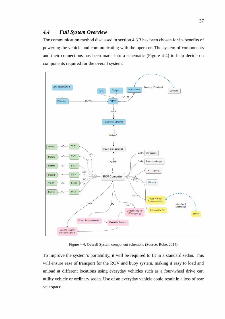
The communication method discussed in section 4.3.3 has been chosen for its benefits of
powering the vehicle and communicating with the operator. The system of components
and their connections has been made into a schematic (Figure 4-4) to help decide on
components required for the overall system.
Figure 4-4: Overall System component schematic (Source: Robe, 2014)
To improve the system’s portability, it will be required to fit in a standard sedan. This
will ensure ease of transport for the ROV and buoy system, making it easy to load and
unload at different locations using everyday vehicles such as a four-wheel drive car,
utility vehicle or ordinary sedan. Use of an everyday vehicle could result in a loss of rear
seat space.

38
4.5 ROV Requirements
4.5.1 Structural Requirements
Structural integrity of the ROV will be verified to be able to withstand the pressure of salt
water at a depth of 100m below sea level. A Factor of Safety of 1.3 shall be applied to all
structural elements of the ROV. The material yield strengths are to be used as the
maximum allowable stresses for the elements, ensuring the safety of all equipment and
continued functionality of the components.
The complete design is required to withstand an external pressure of 1.01MPa, with a
FOS of 1.3, this makes the minimum permissible pressure 1.313MPa.
4.5.2 Electrical Requirements
The electrical requirements for the ROV, at a minimum, need to run all sensory
equipment, the Variable Ballast System and all motors simultaneously. This may not
necessarily happen at any stage during operation, but will ensure that the power
requirements will be satisfactory in the worst case situation. Commonly the use of the
low power draw sensors will be operational, however the major drain will be in the
motors’ draw (typically 4 motors in operation simultaneously). Therefore it is important
for the tether to also accept a standard voltage of 240V with a small amperage draw which
will be inverted to a lower voltage 12V and higher amperage.
If the computer fails to operate while it should be in operation, there needs to be a failsafe
to return the ROV to the surface and send out a beacon notifying the operators of the
failure. The failure protocol will notify the operators which component has failed. The
exact reason why, will not be included in the error, but an error message stating the failed
component will help narrow down as to why it may have failed.
39
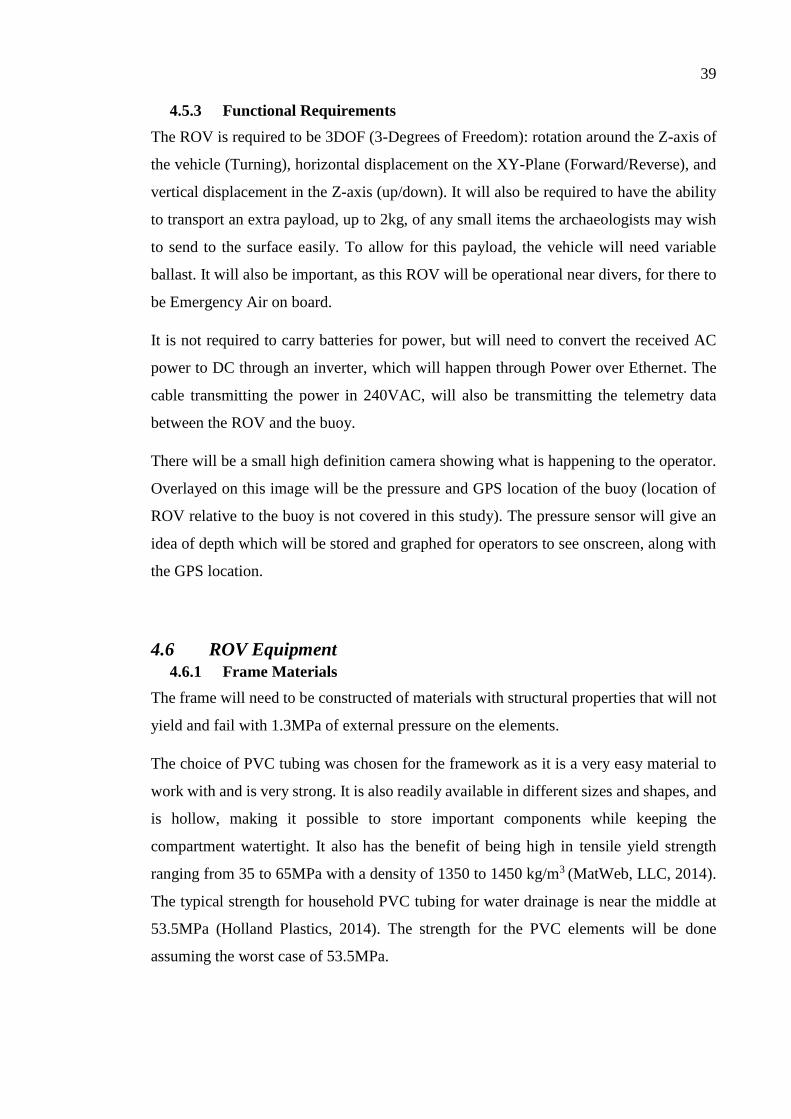
4.5.3 Functional Requirements
The ROV is required to be 3DOF (3-Degrees of Freedom): rotation around the Z-axis of
the vehicle (Turning), horizontal displacement on the XY-Plane (Forward/Reverse), and
vertical displacement in the Z-axis (up/down). It will also be required to have the ability
to transport an extra payload, up to 2kg, of any small items the archaeologists may wish
to send to the surface easily. To allow for this payload, the vehicle will need variable
ballast. It will also be important, as this ROV will be operational near divers, for there to
be Emergency Air on board.
It is not required to carry batteries for power, but will need to convert the received AC
power to DC through an inverter, which will happen through Power over Ethernet. The
cable transmitting the power in 240VAC, will also be transmitting the telemetry data
between the ROV and the buoy.
There will be a small high definition camera showing what is happening to the operator.
Overlayed on this image will be the pressure and GPS location of the buoy (location of
ROV relative to the buoy is not covered in this study). The pressure sensor will give an
idea of depth which will be stored and graphed for operators to see onscreen, along with
the GPS location.
4.6 ROV Equipment
4.6.1 Frame Materials
The frame will need to be constructed of materials with structural properties that will not
yield and fail with 1.3MPa of external pressure on the elements.
The choice of PVC tubing was chosen for the framework as it is a very easy material to
work with and is very strong. It is also readily available in different sizes and shapes, and
is hollow, making it possible to store important components while keeping the
compartment watertight. It also has the benefit of being high in tensile yield strength
ranging from 35 to 65MPa with a density of 1350 to 1450 kg/m3 (MatWeb, LLC, 2014).
The typical strength for household PVC tubing for water drainage is near the middle at
53.5MPa (Holland Plastics, 2014). The strength for the PVC elements will be done
assuming the worst case of 53.5MPa.
40
For the camera and electronics bay, a transparent acrylic PMMA tube will be used. These
have a yield strength ranging from 48 to 76MPa with it typically being 60MPa with a
density of 1170 – 1180kg/m3 (Holland Plastics, 2014).
The maximum permissible stress these tubes can withstand is called the hoop stress. Hoop
stress (𝜎ℎ [𝑀𝑃𝑎]) is solved by the following formula for thin-walled pressure vessels:
𝜎ℎ =𝑝𝑟
𝑡
This is rearranged to give the maximum pressure (p)…
𝑝 =𝜎ℎ𝑡
𝑟 (4.1)
Where 𝑡 is the wall-thickness of the pressure vessel in metres (m)
𝑟 is the radius of the pressure vessel in metres (m)
𝜎ℎ is the hoop stress on the pressure vessel in mega pascals (MPa)
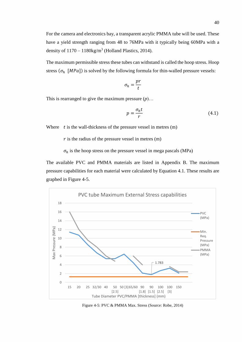
The available PVC and PMMA materials are listed in Appendix B. The maximum
pressure capabilities for each material were calculated by Equation 4.1. These results are
graphed in Figure 4-5.
Figure 4-5: PVC & PMMA Max. Stress (Source: Robe, 2014)
1.783
0
2
4
6
8
10
12
14
16
18
15 20 25 32/30 40 50[2.5]
50 [3]65/60 90[1.8]
90[1.5]
100[2.5]
100[3]
150
Max
Pre
ssu
re (
MP
a)
Tube Diameter PVC/PMMA [thickness] (mm)
PVC tube Maximum External Stress capabilities
PVC(MPa)
Min.Req.Pressure(MPa)
PMMA(MPa)

41
As the vessel is required to withstand a pressure of 1.3MPa (4.5.1), all sizes of PVC and
PMMA tubing will be suitable. Both PVC and PMMA far outdo this requirement, the
smallest for the PMMA tubing being 2.4MPa and PVC being 1.783MPa. With a 1.3 FOS,
the tubing would be able to dive to a depth of 136.4m with no yielding issues.
4.6.2 Thrust & Motor Layout
Thrust was covered in Section 3.6, highlighting the main equation for forward thrust.
Initially, the layout for the motors was chosen to be very simple, as per Figure 4-6.
Figure 4-6: Preliminary motor layout (Source: Robe, 2014)
It was noted, however that if an acute angle between the motor thrust direction and the
actual thrust direction was introduced it would help the ROV pivot better on the z-axis
(Figure 4-7). This reduces the previous forward and reverse thrust for the vessel but can
increase its rotation to be very nimble.
42
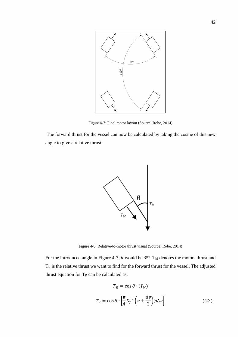
Figure 4-7: Final motor layout (Source: Robe, 2014)
The forward thrust for the vessel can now be calculated by taking the cosine of this new
angle to give a relative thrust.
Figure 4-8: Relative-to-motor thrust visual (Source: Robe, 2014)
For the introduced angle in Figure 4-7, 𝜃 would be 35o. TM denotes the motors thrust and
TR is the relative thrust we want to find for the forward thrust for the vessel. The adjusted
thrust equation for TR can be calculated as:
𝑇𝑅 = cos 𝜃 ∙ (𝑇𝑀)
𝑇𝑅 = cos 𝜃 ∙ [π
4𝐷𝑝
2 (𝑣 +∆𝑣
2) 𝜌∆𝑣] (4.2)

43
Where 𝜃 is the introduced angle between 0o and 90o
𝐷𝑃 is the diameter of the propeller in metre/s (𝑚)
𝑣 is the velocity of incoming flow in metres per second (𝑚. 𝑠−1)
∆𝑣 is the additional velocity/acceleration by propeller in metres per sec (𝑚. 𝑠−1)
𝜌 is the density of the liquid in kilograms per cubic metre (𝑘𝑔/𝑚3)
An increase in theta will reduce the forward thrust by a set percentage relative to the
change in the angle. As theta increases, the amount percentage of actual motor thrust (TM)
used for the forward thrust (TR) can be seen in Figure 4-9. At 350 the motor outputs 81.9%
of its actual thrust in the forward direction.
Figure 4-9: Percentage of utilised motor (Source: Robe, 2014)
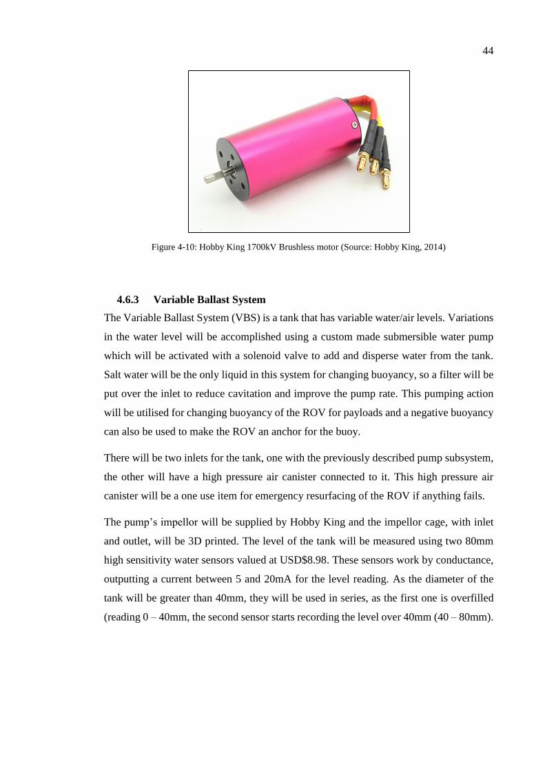
The motors are 1700kV motors from Hobby King. These are high torque motors and have
been chosen for example costing purposes only as tests would need to be done to find the
optimal setup for the motor and propeller choices.
0
20
40
60
80
100
120
0 5 10 15 20 25 30 35 40 45 50 55 60 65 70 75 80 85 90
% o
f m
oto
r th
rust
uti
lised
Angle
Percentage of used Motor Thrust used
44
Figure 4-10: Hobby King 1700kV Brushless motor (Source: Hobby King, 2014)
4.6.3 Variable Ballast System
The Variable Ballast System (VBS) is a tank that has variable water/air levels. Variations
in the water level will be accomplished using a custom made submersible water pump
which will be activated with a solenoid valve to add and disperse water from the tank.
Salt water will be the only liquid in this system for changing buoyancy, so a filter will be
put over the inlet to reduce cavitation and improve the pump rate. This pumping action
will be utilised for changing buoyancy of the ROV for payloads and a negative buoyancy
can also be used to make the ROV an anchor for the buoy.
There will be two inlets for the tank, one with the previously described pump subsystem,
the other will have a high pressure air canister connected to it. This high pressure air
canister will be a one use item for emergency resurfacing of the ROV if anything fails.
The pump’s impellor will be supplied by Hobby King and the impellor cage, with inlet
and outlet, will be 3D printed. The level of the tank will be measured using two 80mm
high sensitivity water sensors valued at USD$8.98. These sensors work by conductance,
outputting a current between 5 and 20mA for the level reading. As the diameter of the
tank will be greater than 40mm, they will be used in series, as the first one is overfilled
(reading 0 – 40mm, the second sensor starts recording the level over 40mm (40 – 80mm).

45
Figure 4-11: High Sensitivity water level (Source: Emart, 2014)
The solenoids for the system will be supplied from Irrigation Store Australia. Their MV75
12VDC Micro Solenoid is has operating specifications of 20kPa to 1.25MPa, which is
appropriate for the application. This does not include operation in sea water at a pressure
of 1.01MPa; a trial pressure test will need to occur to ensure its plastic case will be
structurally sound for underwater use. Figure 4-12 shows the solenoid with the two male
ends for the inlet/outlet which is capable of a 5 to 50 Litres per minute flow rate.
Figure 4-12: MV75 Micro 12V Solenoid (Source: Irrigation Australia, 2014)

46
4.6.4 Camera, Telemetry and tether
The camera chosen for the ROV will be a standard 1080p web camera running at 30FPS.
Web cameras are already designed for low data rates, making them ideal for this
application. 3D imagery will not be used as it requires a large bandwidth and is above the
requirements for the design. The web camera will be in a separate sealed unit than the
other computer components. A Logitech HD Pro c920 has been chosen as the brand is
reputable and known for its reliability.
Figure 4-13: Logitech HD Pro Webcam C920 (Source: Logitech, 2014)
To increase the clarity of the camera’s footage, the addition of two individual High
powered LEDs will be used. The chosen LEDs are a 12W adjustable current LED by
Luminus. The SST-90 has adjustable drive currents from 1A to 9A, allowing adjustable
brightness for the LED, which will be required when looking directly at divers.
Figure 4-14: Luminus SST-90 LED (Source: lck-led, 2014)
All data produced by the pressure sensors, camera, gyroscope and tank level for the
variable ballast system will be passed through the computer system and transmitted
through a tether by means of Power over Ethernet.
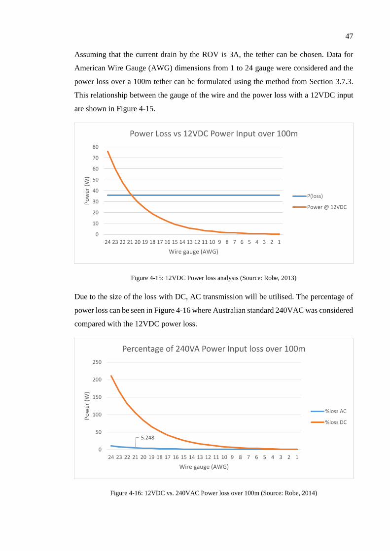
47
Assuming that the current drain by the ROV is 3A, the tether can be chosen. Data for
American Wire Gauge (AWG) dimensions from 1 to 24 gauge were considered and the
power loss over a 100m tether can be formulated using the method from Section 3.7.3.
This relationship between the gauge of the wire and the power loss with a 12VDC input
are shown in Figure 4-15.
Figure 4-15: 12VDC Power loss analysis (Source: Robe, 2013)
Due to the size of the loss with DC, AC transmission will be utilised. The percentage of
power loss can be seen in Figure 4-16 where Australian standard 240VAC was considered
compared with the 12VDC power loss.
Figure 4-16: 12VDC vs. 240VAC Power loss over 100m (Source: Robe, 2014)
0
10
20
30
40
50
60
70
80
24 23 22 21 20 19 18 17 16 15 14 13 12 11 10 9 8 7 6 5 4 3 2 1
Po
wer
(W
)
Wire gauge (AWG)
Power Loss vs 12VDC Power Input over 100m
P(loss)
Power @ 12VDC
5.248
0
50
100
150
200
250
24 23 22 21 20 19 18 17 16 15 14 13 12 11 10 9 8 7 6 5 4 3 2 1
Po
wer
(W
)
Wire gauge (AWG)
Percentage of 240VA Power Input loss over 100m
%loss AC
%loss DC

48
As AWG21 only has a loss of ~5% it has been chosen. This loss will leave an input power
of ~227.4VAC at the ROV which is sufficient for an AC to DC converter.
4.6.5 Computer & Electronic Equipment
A Beaglebone Black with three Arduino boards will be used to control the ROV and
record all data produced by the other components of the ROV. The Beaglebone Black
will be the main processing unit, capable with interfacing with the Ethernet network.
Figure 4-17: Beaglebone Black (Source: elinux, 2014)
There will be one Arduino MEGA board which will compute the Tank Level of the VBS
and can feed the telemetry from the sensors back to the BeagleBone Black. The Arduino
MEGA v3 has been chosen as it has 16 Analog input pins; where it is required to use only
5(2 – pressure, 1 – VBS level, 2 - Solenoids) this will leave 11 spare analog ports for
other sensors in the future. This board has enough computing power to be the driver for
the motors as well. The 54 digital I/O ports will be capable of outputting to the motor
and the orientation sensor (gyroscope and accelerometer). Initially, a bread board will be
utilised to test the second board’s operation with an Arduino MEGA board before
construction a custom board.

49
Figure 4-18: Arduino MEGA (Source: Marian, 2014)
The two solenoids only require outputs, but these will be fed back into the analog inputs
to show when they are on and off. The pressure sensors will be set at two different
locations on the ROV to allow for averaging to occur; this will be a feasible solution to a
usually expensive use of depth perception measurement.
This computing equipment was chosen as it is light weight and compact.
The analog absolute pressure sensor is a P51-3000psi cylindrical device valued at USD
$96.20. Using piezoresistive technology the sensor outputs an analog signal between 4 to
20mA when pressure between 0 and 3000psi (20.684MPa) is applied to it. The maximum
measureable pressure by this sensor far exceeds the system models required depth.
Figure 4-19: Piezoresistive pressure sensor (Source: digi-key, 2014)
There is a 9DOF (nine degrees of freedom) gyroscope/accelerometer/magnetometer will
be included. The chosen model is a Pololu MiniMU-9 valued at USD$14.95. The device
measures the change in angle per second with the gyroscope, the g-forces by the

50
accelerometer and the gauss (magnetic field) by the magnetometer. Table 4-1 shows the
IMU’s measurements step-sizes.
Table 4-1: MinIMU-9 9DOF measuring capabilities (Source: Pololu, 2014)
Measurement Measurement Units Sensor
± 250, ± 500, ±2000 o/s (change in angle per
second)
Gyroscope
±2, ±4, ±8, ±16 g (g-force) Accelerometer
±1.3, ±1.9, ±2.5, ±4, ±4.7, ±5.6, ±8.1 Gauss (magnetic field) Magnetometer
Figure 4-20: MinIMU-9 9DOF Gyro, Compass, Accelerometer (Source: Pololu, 2014)
For voice communication with the divers, a modulated ultrasound device will need to be
altered to work with the Beaglebone Black. The ROV will be inclusive of an Ultrasonic
voice communicator.
The ultrasonic voice communicator chosen is an Ocean Reef GSM G-Power
Communicator. It has a range of 500m and has a runtime of 25hrs. The device will require
alteration to work with the computer/phone.
Figure 4-21: Ocean Reef GSM G-Power communicator (Source: Ocean Reef, 2014)

51
Unfortunately, this device has a maximum permissible depth of ~40 metres. The reason
behind this is not specified by Ocean Reef. The product would need to be examined and
reinforced to allow for a depth possibility of 100m.
4.7 Final ROV Design
4.7.1 Structural Analysis
NOTE: The detailed drawings for this section can be found in Appendix C.5. Also, the
hard 90o corners have been drawn for a higher probability of successful fluid analysis to
occur.
Three preliminary designs were created after the preliminary research. Two of which were
very similar and are not included in this study. The two designs included function in
completely different ways and can be seen in Appendix C.1. The second design would be
the least expensive option of the two, but it is not as easy to adjust for different payloads.
For this single reason design 1, the cubic shaped one, has be slightly altered for the final
design.
The final model has a large compartment for housing the major computing components
(4.6.5) shown in green and a small transparent tube for holding the camera and two LEDs.
The model also features two large 2.776L buoyancy chambers and two narrow 0.954L
weights for concentrating the centre of mass in a lower position. All of these chambers
are designed to be attached using ordinary electronics zip ties.
The model has a wet weight of 5.101kg (Appendix C.4) and measures 639.4mm long by
449.03mm wide by 450mm high. These dimensions make for a relatively small ROV,
which would be very easy to transport.

52
Figure 4-22: Final ROV Design (Source: Robe, 2014)
NOTE: Figure 4-22 shows the ROV without a mesh on the bottom. The mesh runs from
corner to corner, fixed between the balance weights and the structure. This mesh will be
required for the prototype to carry a payload(s) up to 2kg.
Figure 4-23: ROV design highlighting balancing weight adjuster (Source: Robe, 2014)
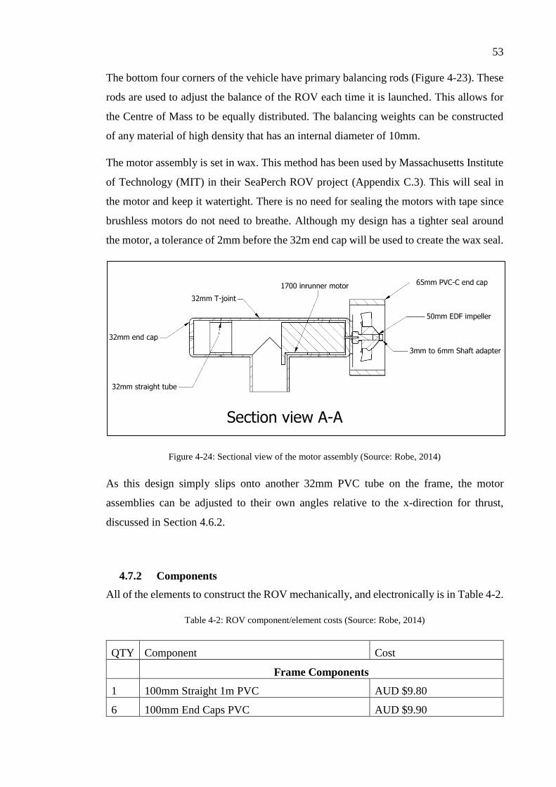
53
The bottom four corners of the vehicle have primary balancing rods (Figure 4-23). These
rods are used to adjust the balance of the ROV each time it is launched. This allows for
the Centre of Mass to be equally distributed. The balancing weights can be constructed
of any material of high density that has an internal diameter of 10mm.
The motor assembly is set in wax. This method has been used by Massachusetts Institute
of Technology (MIT) in their SeaPerch ROV project (Appendix C.3). This will seal in
the motor and keep it watertight. There is no need for sealing the motors with tape since
brushless motors do not need to breathe. Although my design has a tighter seal around
the motor, a tolerance of 2mm before the 32m end cap will be used to create the wax seal.
Figure 4-24: Sectional view of the motor assembly (Source: Robe, 2014)
As this design simply slips onto another 32mm PVC tube on the frame, the motor
assemblies can be adjusted to their own angles relative to the x-direction for thrust,
discussed in Section 4.6.2.
4.7.2 Components
All of the elements to construct the ROV mechanically, and electronically is in Table 4-2.
Table 4-2: ROV component/element costs (Source: Robe, 2014)
QTY Component Cost
Frame Components
1 100mm Straight 1m PVC AUD $9.80
6 100mm End Caps PVC AUD $9.90
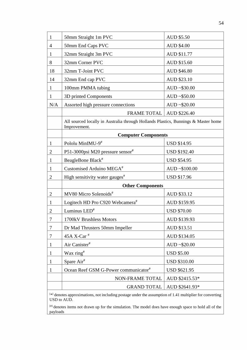
54
1 50mm Straight 1m PVC AUD $5.50
4 50mm End Caps PVC AUD $4.00
1 32mm Straight 3m PVC AUD $11.77
8 32mm Corner PVC AUD $15.60
18 32mm T-Joint PVC AUD $46.80
14 32mm End cap PVC AUD $23.10
1 100mm PMMA tubing AUD ~$30.00
1 3D printed Components AUD ~$50.00
N/A Assorted high pressure connections AUD ~$20.00
FRAME TOTAL AUD $226.40
All sourced locally in Australia through Hollands Plastics, Bunnings & Master home
Improvement.
Computer Components
1 Pololu MinIMU-9# USD $14.95
2 P51-3000psi M20 pressure sensor# USD $192.40
1 BeagleBone Black# USD $54.95
1 Customised Arduino MEGA# AUD ~$100.00
2 High sensitivity water gauges# USD $17.96
Other Components
2 MV80 Micro Solenoids# AUD $33.12
1 Logitech HD Pro C920 Webcamera# AUD $159.95
2 Luminus LED# USD $70.00
7 1700kV Brushless Motors AUD $139.93
7 Dr Mad Thrusters 50mm Impeller AUD $13.51
7 45A X-Car # AUD $134.05
1 Air Canister# AUD ~$20.00
1 Wax ring# USD $5.00
1 Spare Air# USD $310.00
1 Ocean Reef GSM G-Power communicator# USD $621.95
NON-FRAME TOTAL AUD $2415.53*
GRAND TOTAL AUD $2641.93*
[*] denotes approximations, not including postage under the assumption of 1.41 multiplier for converting
USD to AUD.
[#] denotes items not drawn up for the simulation. The model does have enough space to hold all of the
payloads
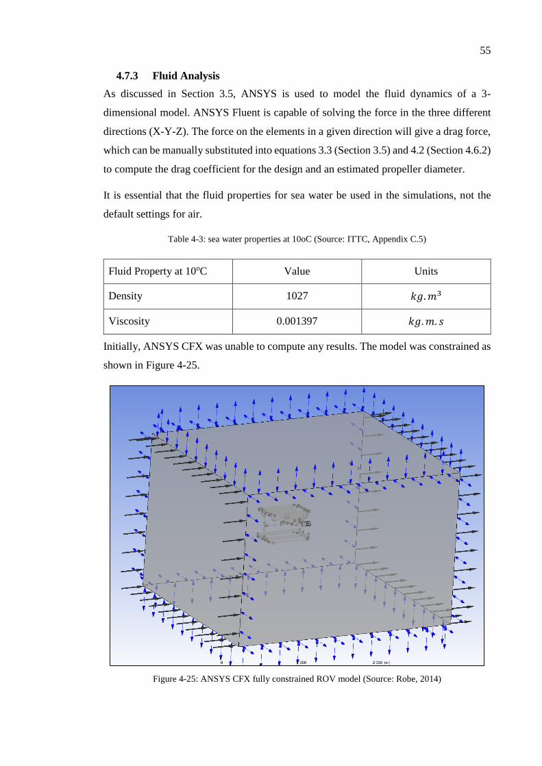
55
4.7.3 Fluid Analysis
As discussed in Section 3.5, ANSYS is used to model the fluid dynamics of a 3-
dimensional model. ANSYS Fluent is capable of solving the force in the three different
directions (X-Y-Z). The force on the elements in a given direction will give a drag force,
which can be manually substituted into equations 3.3 (Section 3.5) and 4.2 (Section 4.6.2)
to compute the drag coefficient for the design and an estimated propeller diameter.
It is essential that the fluid properties for sea water be used in the simulations, not the
default settings for air.
Table 4-3: sea water properties at 10oC (Source: ITTC, Appendix C.5)
Fluid Property at 10oC Value Units
Density 1027 𝑘𝑔. 𝑚3
Viscosity 0.001397 𝑘𝑔. 𝑚. 𝑠
Initially, ANSYS CFX was unable to compute any results. The model was constrained as
shown in Figure 4-25.
Figure 4-25: ANSYS CFX fully constrained ROV model (Source: Robe, 2014)

56
The Blue arrows in the simulation window show an open boundary (allow water to flow
out, but not directly) the two black arrows are the inlet and outlet.
Since CFX was giving errors, another one of ANSYS’ other fluid modelling programs,
Fluent was used. ANSYS Fluent is not a very user friendly program when used for such
a short period. However, results for a partially complete model were attainable.
Figure 4-26: Incredibly simplified version on the inventor model for ANSYS (Source: Robe, 2014)
It is unknown whether this was due to lack of computing power or the program that was
causing these issues. Results produced by Fluent can be viewed in three different
methods. They are: graphics and animations, plots/graphs, and reports. If a simulation in
Fluent is setup to compute forces in each plane, it is possible to find the drag or lift forces
produced from an object in any fluid. Figure 4-27 shows an outputted result for the static
pressure on and around a simplified version of the final. This result was used to compute
the approximate drag force of the final design. It is interesting how much turbulence is
caused by the two buoyancy capsules. This will not be of concern for the design as the
ROV will never operate at this speed in real operating conditions. The simulations done
use inputs for the fluid velocity, specified by initial boundary conditions.

57
Figure 4-27: ANSYS Fluent simulation result with pathlines representing static pressure (Pa) (Source:
Robe, 2014)
The dialogue window underneath this image can print out the previously mentioned
reports. For the simulations in this study, drag force is considered. So a monitor is
required for the program to compute the results. To do this, create a Drag Monitor in the
monitor subsection. After selecting the monitor, designate which force vector(s) required
for the program to watch. In Figure 4-28 the drag force on the wall-solid object (naming
for the ROV) in the X-Y-Z vectors is considered. This is not the magnitude of all three
vectors, it can be chosen later to only investigate one of the three.

58
Figure 4-28: Drag monitor inputted for drag force in the X-Y-Z vectors (Source: Robe, 2014)
The results for a drag force (𝐹𝐷) on the revised model for ANSYS (Figure 4-26) showed
27.415815 N. ANSYS is also capable of deriving the projected area in a specified vector,
for the y-direction of the model (direction of fluid on ROV). The results for the same
model were 0.488991m2.
Substituting these values into the equation for drag force and thrust can give the drag
coefficient and required propeller diameter needed for this vehicle. The drag coefficient
for the model is 0.109 and the recommended propeller diameter is 62.83mm. This is
lightly larger than the previously chosen propeller, but as stated in Section
The method taken to get from a 3-dimensional model to a working simulation through
ANSYS Fluent can be read through, step-by-step in Appendix C.6.

59
4.8 Buoy
4.8.1 Structural Requirements
The structural integrity of this model uses the same basic modelling as with the ROV, but
the buoy is required to be easily visible on the surface of the water. The design will be
assumed to take no impact from any normal water vessels.
The structure will be completely sealed with a Photovoltaic (PV) panel on the surface.
With the added weight of the PV panel(s) and the battery bank, the buoy shall continue
to be buoyant. To achieve this a buoyancy of +20% of the weight of the buoy will be
required to keep it completely buoyant 24/7.
4.8.2 Electronic Requirements
The electronics on board of the buoy take higher priority than that of the ROVs. It will
have a cut-off setting so the buoy will always be capable of continuous data transfer so
the ROV and buoys’ location will never be lost. This cut-off will be applied once the total
energy drain is computed for the components on the buoy (GPS, compass and wireless
communication link).
The battery capacity is required to be sufficient for a continuous runtime for the ROV of
3 hours (optimal will be found). This is a long period of time for a ROV to be functioning,
but will give operators of the ROV ample time to move it before conversing the divers.
The cost of this high capacity setup will cause the buoy to be extremely heavy. There will
be an optimal weight to ROV runtime to be found; this will only be solvable once a
prototype will be built.
60
4.8.3 Functional Requirements
The minimum functional requirements of the buoy are:
Compass, to give a heading for the buoy (not the ROV, this is outside of the scope
of this system model),
GPS (Global Positioning System), to give a location (of the buoy, not the ROV)
Batteries, for powering the whole system
PV Panels, to charge the batteries continuously in 12hours
Wireless communication with Traditional IP Network (achievable through a
mobile phone device or long-distance WIFI)
Wireless communication with the Divers
A spoolable 100m roll of 2-core 16AWG wire
4.9 Buoy Equipment
4.9.1 Photovoltaic Panel(s) & battery bank
Assuming that the current requirements for the ROV are approximately 10Ah total
storage for 1hour operation, for a 3hr operating duration approximately 35Ah will be
required. This will leave an extra 5Ah for the buoy to continue operation when the rest of
the power is drained by the ROV. There are many different types of low capacity batteries
available: NiCd(Nickle Cadium), NiMH(Nickle-Methal Hydride), LiIon(Lithium Ion),
LiPo(Lithium Polymer). Higher capacity batteries are typically lead-acid and are used in
cars. These lead acid batteries are designed with a high burst current (for starting engines)
– they are not designed to be completely discharged and recharged frequently.
Batteries which allow for complete discharging and recharging are Deep Cycle batteries.
These are high capacity and are constructed from tougher lead components and different
conductor types. The two best conductor options for a constantly shifting buoy are the
Gel and AGM versions as there is no chance of spillage.
AGM batteries are a battery utilising Absorbed Glass Mat (AGM) technology as a
sponge-like material. This sponge-like material suspends the electrolyte within high
porous glass fibre mat separators. These differ from the more expensive option of gel
batteries, which use a gel to hold the battery plates securely in place. Both versions of

61
these batteries offer no chance of spillage and are incredibly sustainable as long as they
do not get over charged.
Battery Barn in Toowoomba offer the FullRiver AGM version battery at 40Ah for AUD
$244. This battery is not orientation specific and it has a slim profile due to its low
amperage rating. These features allow for multiple batteries to be installed in a low profile
area.
Requiring a 35Ah, 420Wh drain from the components a 56.875Ah minimum battery
capacity will be required. Assuming a 30% safety net for discharge and a power
consumption of 80% (for a sustainable battery life) of the battery’s capacity…
The chosen batteries will be capable of a total discharge time of ~6.4hrs until the 80%
battery limitation is met.
Figure 4-29: Century Deep Cycle Gel battery (Source: Century Batteries, 2014)
Photovoltaic Panels convert solar radiation to DC electricity. The PV panel chosen is a
USD $209.95 semi-flexible 62W solar panel that would take ~18.5hrs to charge the
battery bank (assuming 30% extra to charge). The standard variant PV panels are very
heavy, weighing about 7.5kg whereas the Kulkyne panel is only 1.3kg. This weight
difference is extremely important to stop the buoy from tipping over.

62
Figure 4-30: 62W Semi-flexible PV Panel (Source: Kulkyne Kampers, 2014)
To avoid any damage occurring to the batteries, a current regulator will be included.
4.9.2 Electronic Components (GPS, Compass & Wireless transmission)
Different types of electronic components were considered, however the decision to
purchase an affordable Android phone would be the best solution. Android phones come
standard with GPS, WiFi, GSM networking and compass capabilities. A Samsung Galaxy
Neo has been chosen as it is the most affordable (AUD$125) Android device available
with full functionality with Australia’s 3G Network.
Figure 4-31: Samsung Galaxy Neo (Source: JB Hifi, 2014)
The second option was to use a WiFi network adapter, typically used in laptops, for the
communication with the operator. This can be adapted with a high power, long distance
antenna. This comes at a higher cost than the Android alternative but would be more
secure and easier to test with another computer. Using a long distance WiFi antenna
option, the GPS and compass would need to be integrated into another computer. If this
method was used, a TP-Link Hi Power long distance signal booster could be used (Figure
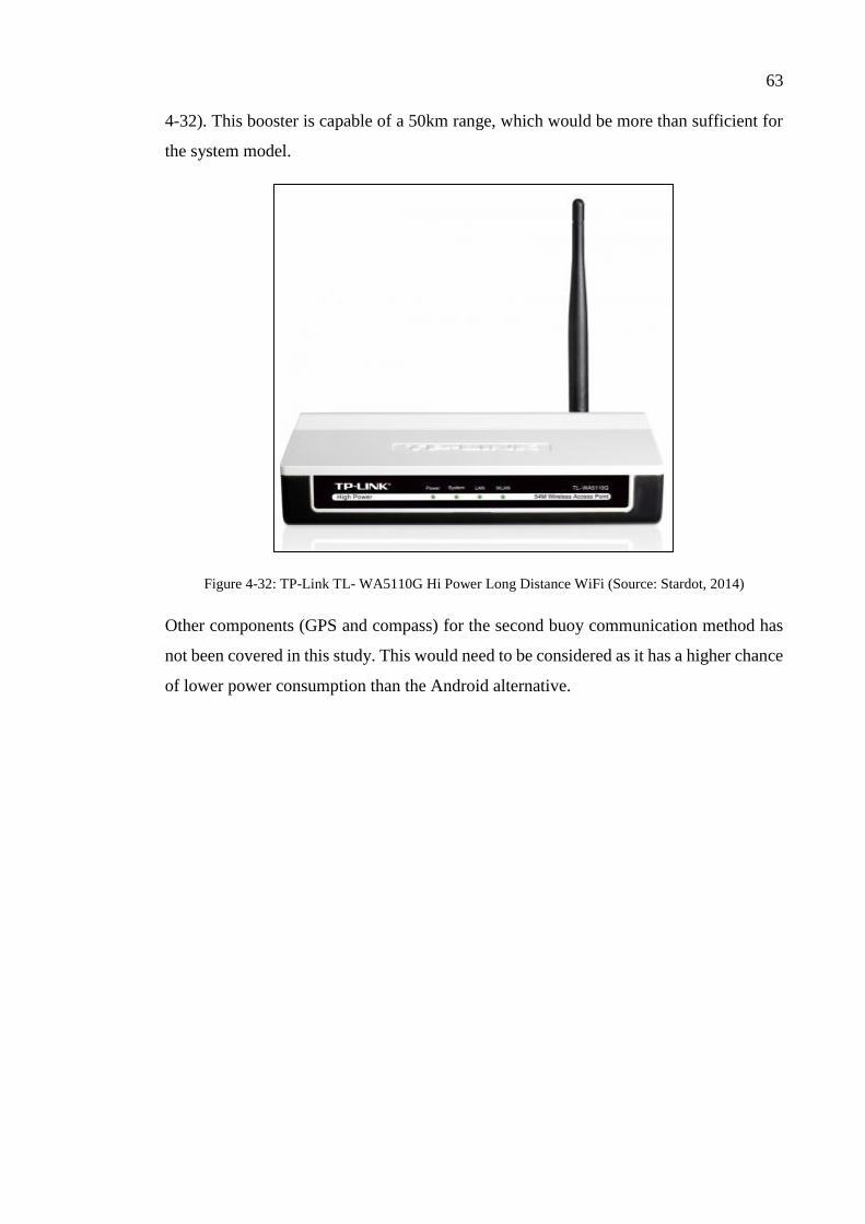
63
4-32). This booster is capable of a 50km range, which would be more than sufficient for
the system model.
Figure 4-32: TP-Link TL- WA5110G Hi Power Long Distance WiFi (Source: Stardot, 2014)
Other components (GPS and compass) for the second buoy communication method has
not been covered in this study. This would need to be considered as it has a higher chance
of lower power consumption than the Android alternative.

64
4.10 Final Buoy Design
3-dimensional models for the buoy concept have not been investigated in detail for this
study. The design will essentially consist of a large electronics box measuring a minimum
of 800 x 540mm to house the Kulkyne PV panel. This box will have a depth slightly larger
than the smallest width of the batteries; for the chosen batteries this is 174mm. One of the
smaller faces will have a plastic spool for the 100m long tether to coil onto. The method
of keeping the tension for the tether has not been covered. The other small face will have
high buoyancy tubing mounted to it.
The battery packs will be mounted relatively close to the absolute middle of the structure.
As they weigh 13.4kg each, the batteries are the main weight component on the buoy.
The buoyancy of the device will need to exceed the sum total weight of the components
by 20% to reduce the chances of submersion and, if submersed, the duration of
submersion.
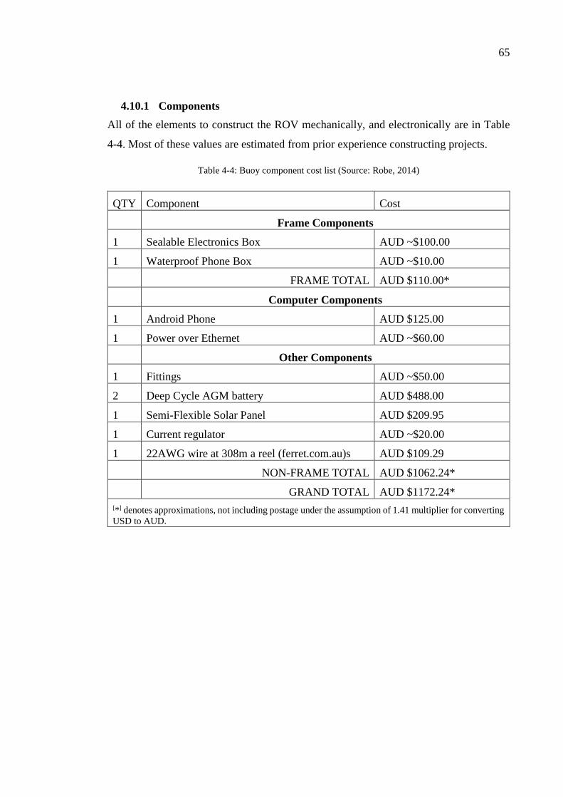
65
4.10.1 Components
All of the elements to construct the ROV mechanically, and electronically are in Table
4-4. Most of these values are estimated from prior experience constructing projects.
Table 4-4: Buoy component cost list (Source: Robe, 2014)
QTY Component Cost
Frame Components
1 Sealable Electronics Box AUD ~$100.00
1 Waterproof Phone Box AUD ~$10.00
FRAME TOTAL AUD $110.00*
Computer Components
1 Android Phone AUD $125.00
1 Power over Ethernet AUD ~$60.00
Other Components
1 Fittings AUD ~$50.00
2 Deep Cycle AGM battery AUD $488.00
1 Semi-Flexible Solar Panel AUD $209.95
1 Current regulator AUD ~$20.00
1 22AWG wire at 308m a reel (ferret.com.au)s AUD $109.29
NON-FRAME TOTAL AUD $1062.24*
GRAND TOTAL AUD $1172.24*
[*] denotes approximations, not including postage under the assumption of 1.41 multiplier for converting
USD to AUD.
66
CHAPTER 5
CONCLUSIONS
This study investigated the problems, trends and needs of marine archaeologists and
ROVs and was successful in designing a system model which would be capable of:
Long-distance, wireless operator control
o Possible with a tether between the ROV and buoy
Live verbal and visual communication with marine archaeologists
In this study these aspects have been researched to be economically and physically
feasible. The ROV communicates with a buoy through a tether. The buoy is capable of
two-way communication with an operator in a remote location.
The ROV’s frame is constructed with PVC tubing. The capsule for video capture is made
from PMMA tubing which is a transparent material. The frame costs a total of AUD
$226.40. The components of the complete system with buoy comes to AUD $3814.17
which is below the AUD $4000 budget. This valuation does not include GST and postage
for items from the United States of America. These extra costings could easily inflate the
cost to over AUD $4000. This would still be a very affordable design as it features two
innovative ideas in its system model listed at the start of this chapter.
If the objective of the research was to have an innovative, sustainable design capable of
only wireless control (i.e. ignoring anything related to divers), the cost immediately drops
to AUD $2500.11. This is achieved by not including the verbal communicator (Ocean
Reef GSM G-Power communicator) and the emergency air for the divers.
The overall design would be relatively easy to transport as the ROV has small dimensions
of 639.4 x 449.03 x 450mm and the buoy can be minimised to being approximately 800
x 540 x 180mm. The package would be quite easy to pack for transport between locations.

67
5.1 Future Work
The testing procedure outlined in Section 3.6 for the propellers, ESCs and motors will
need to be done. Currently, these tests have never been done for the non-standard hobby
market components.
Before building the main structure, the testing of the theoretical electronic system will
need to be dry tested. This will ensure that the system will be sufficient for continuous
work without load. A beneficial addition would be a method of ascertaining the location
of the ROV relative to the buoy.
Another subsection which requires more work is a variable ballast system. The
submersible pump has to withstand a pressure of 1.01MPa while pumping water into a
tank. The design of the impeller, choice of motors and choice of valves is very important
here.
Building and testing of a prototype of the elements of the system model, primarily the
ROV, is necessary to evaluate if the computed values are accurate before doing field
work.

68
REFERENCES
ACSA Alcen, 2014. Sea Explorer. [Online]
Available at: http://www.acsa-alcen.com/robotics/seaexplorer
[Accessed 2014].
BlueFin Robotics, 2014. Bluefin-21. [Online]
Available at: http://www.bluefinrobotics.com/products/bluefin-21/
[Accessed 2014].
Butler, L., 1987. Underwater Radio Communication. Amateur Radio, pp. 1-8.
Coxworth, B., 2012. Casio device lets scuba divers converse underwater. [Online]
Available at: http://www.gizmag.com/casio-logosease-scuba-communications/24998/
[Accessed 2014].
DEEP SEA SYSTEMS International, 2014. Global Explorer ROV. [Online]
Available at: http://www.deepseasystems.com/index.php/home/global-explorer-rov
[Accessed 2014].
Denoble, M. P. & Douglas, E., 2009. Emergency Ascents: Managing the Risks. [Online]
Available at: http://www.alertdiver.com/226
[Accessed 2014].
Denoble, P. J., Marroni, A. & Vann, R. D., 2008. Annual Fatality Rates and Associated
Risk, Durham, NC: Divers Alert Network.
Dimension Engineering LLC, 2014. What is an accelerometer?. [Online]
Available at: http://www.dimensionengineering.com/info/accelerometers
[Accessed 2014].
DIVEworks, 2014. Work Class ROV Services. [Online]
Available at: http://www.diveworks.com.au/work_class_rov_services
[Accessed 2014].
Goh, J. H., Shaw, A. & Al-Shamma'a, A. I., 2009. Underwater Wireless Communication
System, Liverpool: IOPscience.
Goodrich, R., 2013. Accelerometer vs. Gyroscope: What's the Difference?. [Online]
Available at: http://www.livescience.com/40103-accelerometer-vs-gyroscope.html
[Accessed 2014].
Guzzio, E. & MacNeill, J., 2008. Defense Contractors Snap Up Submersible Robot
Gliders. IEEE Spectrum, 1 September.
Hobby King, 2014. B28-57-17L Brushless Inrunner 1700kv. [Online]
Available at:
http://www.hobbyking.com/hobbyking/store/__28394__B28_57_17L_Brushless_Inrun
ner_1700kv.html
[Accessed 2014].
Holland Plastics, 2014. Acrylic Rod & tube (PMMA). [Online]
Available at:
http://www.hollandplastics.com.au/process/catalogue/itemView.html?itemId=161797&

69
categoryId=5657
[Accessed 2014].
Holland Plastics, 2014. Material Properties. [Online]
Available at:
http://www.hollandplastics.com.au/process/actions/galleryView.html?process=actions%
2FgalleryView.php&categoryId=5793
[Accessed 2014].
integral LED, 2014. What are Lumens?. [Online]
Available at: http://www.integral-led.com/education/what-are-lumens
[Accessed 2014].
Kendig, B., 2007. Got Air?. [Online]
Available at: http://www.scubadiving.com/gear/accessories/got-air
[Accessed 2014].
Kongsberg, 2014. Underwater Altimeter. [Online]
Available at:
http://www.km.kongsberg.com/ks/web/nokbg0240.nsf/AllWeb/188AD958095B7127C1
256CFC00300A95?OpenDocument
[Accessed 2014].
Logitech, 2014. Logitech HD Pro Webcam C920. [Online]
Available at: http://www.logitech.com/en-au/product/hd-pro-webcam-c920?crid=34
[Accessed 2014].
MatWeb, LLC, 2014. Overview of materials for Chlorinated PVC. [Online]
Available at:
http://www.matweb.com/search/DataSheet.aspx?MatGUID=95485918927a4efcb67dc7
35800f8912&ckck=1
[Accessed 2014].
MIT: Sea grant, 2011. MIT's sea Grant's Sea Perch, Massachusetts: Massachusetts
Institute of Technology.
MiTAC International, 2014. How does GPS work?. [Online]
Available at: http://www.mio.com/technology-gps-work.htm
[Accessed 2014].
NASA, 2014. Shape Effects on Drag. [Online]
Available at: http://www.grc.nasa.gov/WWW/k-12/airplane/shaped.html
[Accessed 2014].
NOAA: National Oceanic and Atmoshperic Administration, 2014. Hercules (ROV) and
friends. [Online]
Available at: http://oceanexplorer.noaa.gov/technology/subs/hercules/hercules.html
[Accessed 2014].
Ocean Reef Group, 2014. Specifications. [Online]
Available at: http://www.oceanreefgroup.com/pdf/docs/doc_comm_system_specs.pdf
[Accessed 2014].
Ocean Reef: Connecting Divers, 2010. UNDERWATER COMMUNICATION. [Online]
[Accessed 2014].
70
OPENROV, 2014. OpenROV: Underwater Exploration Robots. [Online]
Available at: http://www.openrov.com/
[Accessed 2014].
Photovoltaic-software, 2014. ELECTRICITY LOSSES : AC AND DC ELECTRICAL
WIRE VOLTAGE DROP AND ENERGY LOSSES ONLINE CALCULATOR. [Online]
Available at: http://photovoltaic-
software.com/DC_AC_drop_voltage_energy_losses_calculator.php
[Accessed 2014].
Royal Life Saving, 2013. National Drowing Report 2013, Australia: Royal Life Saving.
Spare Air, 2014. Spare Air. [Online]
Available at: http://www.spareair.com/index.html
[Accessed 2014].
Stojanovic, M., n.d. Underwater Acoustic Communication. Wiley Encyclopedia of
Electrical and Electronics Engineering, pp. 4-9.
Tarmey, C., 2006. RUSSIAN NAVY TO FLY ROV TO SUBMARINE DISASTERS.
[Online]
Available at: http://www.seaeye.com/whatsnew_2006.html
[Accessed 2014].
Urban, M. W., Fatemi, M. & Greenleaf, J. F., 2010. Modulation of ultrasound to produce
multifrequency radiation force, s.l.: Acoustical Society of America.
Vinidex, 2014. PVC Properties. [Online]
Available at: http://www.vinidex.com.au/technical/material-properties/pvc-properties/
[Accessed 2014].
Wolfe, J., n.d. Electric motors and generators. [Online]
Available at:
http://www.animations.physics.unsw.edu.au/jw/electricmotors.html#ACmotors
[Accessed 2014].
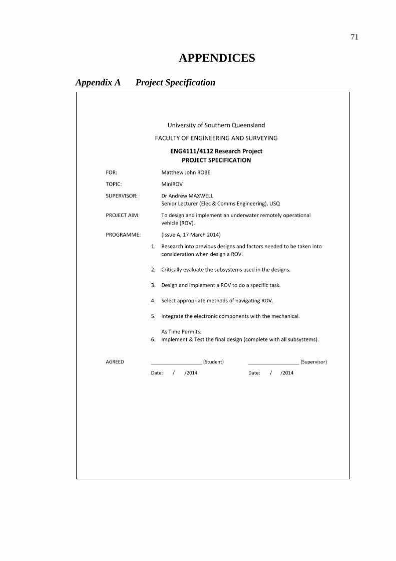
71
APPENDICES
Appendix A Project Specification

72
Appendix B Table of Materials
PVC
Outside
Diameter
(mm)
Thickness
(mm)
Description Length
(mm)
Max
pressure
(MPa)
15 1.6 Full Length – Straight 1000 11.413
20 2 Full length - Straight 1000 10.7
25 2 Full length – Straight 1000 8.56
32 2 Full length – Straight 1000 6.688
40 2 Full length – Straight 1000 5.35
50 2.5 Full length – Straight 1000 5.35
50 3 Full length – Straight 5000 6.42
65 2.5 Full length – Straight 1000 4.458
90 1.8 Full length – Straight 1000 2.14
90 1.5 Full length – Straight 5000 1.783
100 2.5 Full length – Straight 1000 2.675
100 3 Full length – Straight 5000 3.21
150 3 Full length – Straight 1000 2.14
Holland Plastics PMMA clear Tubing
15 2 Full Length – Straight N/A 16
20 2 Full Length – Straight N/A 12
25 2 Full Length – Straight N/A 9.6
30 2 Full Length – Straight N/A 8
40 2 Full Length – Straight N/A 6
50 2 Full Length – Straight N/A 4.8
60 3 Full Length – Straight N/A 6
90 3 Full Length – Straight N/A 4
100 3 Full Length – Straight N/A 3.6
150 3 Full Length – Straight N/A 2.4
200 4 Full Length – Straight N/A 2.4

73
Appendix C ROV Design
Appendix C.1 ROV preliminary designs
Design #1: A small, simple 3 motor ROV.
(should have a clear cap on the left most face of the major 150mm element)
Design #2: A small, complex to build, cheap to manufacture ROV.

74
Appendix C.2 ROV Detailed Drawings
NOTE: All final drawings do not include the corner 900 PVC-C. This was done for the
simulations, as they have a higher chance of success when using a smaller number of parts.
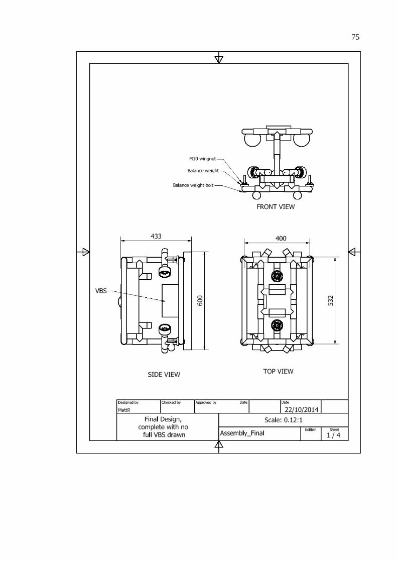
75

76

77
Appendix C.3 MIT Wax for waterproofing (pages 9-11)
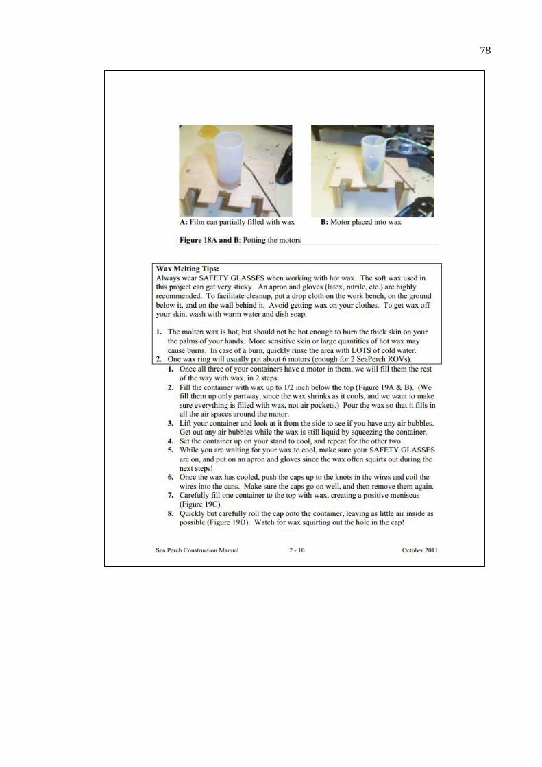
78
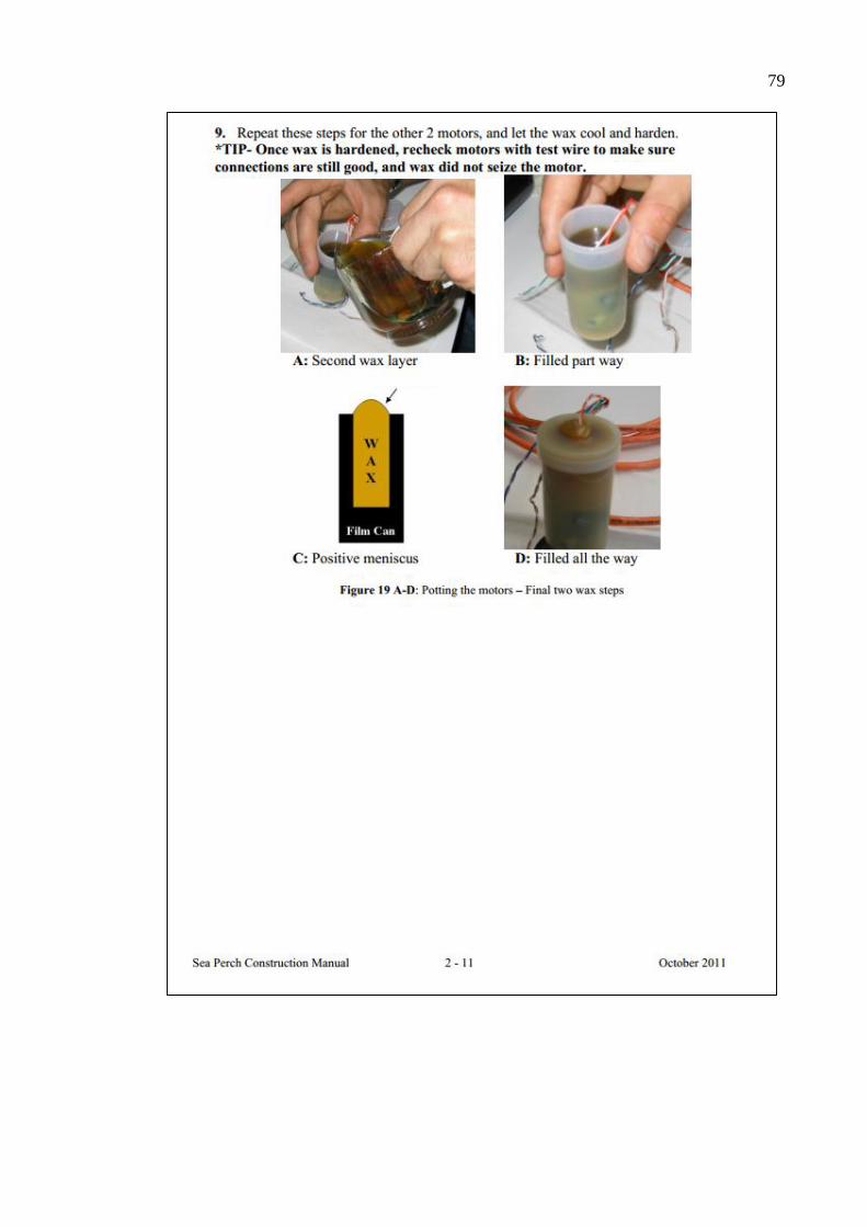
79

80
Appendix C.4 ROV Buoyancy calculations using PTC MathCAD®.

81

82

83
Appendix C.5 Sea Water Properties
Appendix C.6 3D *.iges models to working simulations
No captions for images here since they are all my work for the walkthrough.
The inventor based *.iam or *.ipt file was saved as a *.iges file for easier manipulation
through ANSYS. ANSYS Workbench is started up, and “Fluid Flow (Fluent) is dragged
to the project schematic to make a standalone fluid analysis. The *.iges file is imported

84
into the geometry by going to the standalone analysis and importing the 3D file into the
geometry, shown below.
This is “edited” so that all parts of the geometry form into one, using the Boolean tool
‘unite’. An enclosure is them produced to encompass the ROV with a 2m buffer, shown
below.
The solid that is the ROV is then subtracted from the enclosure to create an interior “wall”.
This leaves an outline of the ROV inside the cube. The tree in the DesignModeler will
look like the below image.

85
Now it’s time to create a mesh of the interior and exterior of the ROV, using the meshing
program (second option down in the standalone analysis tool). The mesh is of medium
grade, which takes a tolerable amount of time to calculate and draw, without taking an
hour or so just to build a mesh. In this section, named selections are done… One called
“INLET VELOCITY” the other “OUTLET PRESSURE”. Now the mesh is generated,
this can take a while…
This is what it looks like with the external mesh and internal mesh done. You can only
see the internal mesh if you activate “Wire Frame” mode. Updating of this mesh is
required back on the Workbench area. Now to set up the simulation…
Enter the “setup” area of the standalone analysis on the Workbench. A window showing
the below will appear.

86
Where the red face is the OUTLET_PRESSURE and the blue face is the
INLET_VELOCITY. “Check” is required in the General area, this checks the mesh so
that there are DEFINITELY no errors. In the “materials” tab, a new fluid is created for
sea_water. Choose a new name, enter it’s density and viscosity, then click on
“change/create”, select no in the “Question” window.
Next the cell zone conditions need to be made. It defaults to air for the enclosure, edit it
to being sea_water. Continue to “Boundary Conditions”, here the inlet velocity is set to
1m/s. Jumping down to “monitors” create whatever monitors are required for the
simulation. I chose to make a drag in the X-Y_Z vectors.
Selection of “Standard Initialization” for the Solution Initialisation is required. Compute
it from the INPUT_PRESSURE. And initialize…
At the bottom of the Solution tree, Select “Run Calculator”. Input desired iterations (I
found 100 to be accurate enough). Check the case… Then run the calculation. This is the
most time consuming part of the simulation. As the software steps through the iterations
until it finds the constants.
Viewing of the results can occur in the “Results” tree, in the form of the plots, print outs
(Reports) and visual aids.