Embed Size (px)
Citation preview

Protection devices
SIRIUS InnovationsSIRIUS 3RU2 / 3RB3 Overload Relays
Manual · 11/2011
Industrial Controls
Answers for industry.

� SIRIUS Innovations - SIRIUS
�3RU2/3RB3 overload relays
___________________
___________________
___________________
___________________
___________________
___________________
___________________
___________________
___________________
___________________
___________________
___________________
___________________
___________________
___________________
___________________
Industrial Controls
Protection devices SIRIUS Innovations - SIRIUS 3RU2/3RB3 overload relays
Manual
11/2011 A5E03656507420A-01
Introduction 1
Standards 2
Product description 3
Product combinations 4
Functions 5
Configuration 6
Mounting 7
Connection 8
Operation 9
Accessories 10
Technical data 11
Circuit diagrams 12
Types of coordination A
References B
Dimension drawings (dimensions in mm)
C
Correction sheet D
Legal information
Legal information Warning notice system
This manual contains notices you have to observe in order to ensure your personal safety, as well as to prevent damage to property. The notices referring to your personal safety are highlighted in the manual by a safety alert symbol, notices referring only to property damage have no safety alert symbol. These notices shown below are graded according to the degree of danger.
DANGER indicates that death or severe personal injury will result if proper precautions are not taken.
WARNING indicates that death or severe personal injury may result if proper precautions are not taken.
CAUTION with a safety alert symbol, indicates that minor personal injury can result if proper precautions are not taken.
CAUTION without a safety alert symbol, indicates that property damage can result if proper precautions are not taken.
NOTICE indicates that an unintended result or situation can occur if the relevant information is not taken into account.
If more than one degree of danger is present, the warning notice representing the highest degree of danger will be used. A notice warning of injury to persons with a safety alert symbol may also include a warning relating to property damage.
Qualified Personnel The product/system described in this documentation may be operated only by personnel qualified for the specific task in accordance with the relevant documentation, in particular its warning notices and safety instructions. Qualified personnel are those who, based on their training and experience, are capable of identifying risks and avoiding potential hazards when working with these products/systems.
Proper use of Siemens products Note the following:
WARNING Siemens products may only be used for the applications described in the catalog and in the relevant technical documentation. If products and components from other manufacturers are used, these must be recommended or approved by Siemens. Proper transport, storage, installation, assembly, commissioning, operation and maintenance are required to ensure that the products operate safely and without any problems. The permissible ambient conditions must be complied with. The information in the relevant documentation must be observed.
Trademarks All names identified by ® are registered trademarks of Siemens AG. The remaining trademarks in this publication may be trademarks whose use by third parties for their own purposes could violate the rights of the owner.
Disclaimer of Liability We have reviewed the contents of this publication to ensure consistency with the hardware and software described. Since variance cannot be precluded entirely, we cannot guarantee full consistency. However, the information in this publication is reviewed regularly and any necessary corrections are included in subsequent editions.
Siemens AG Industry Sector Postfach 48 48 90026 NÜRNBERG GERMANY
Order number: 3ZX1012-0RU20-5AC1 Ⓟ 11/2011 Technical data subject to change
Copyright © Siemens AG 2011. All rights reserved
SIRIUS Innovations - SIRIUS 3RU2/3RB3 overload relays
Manual, 11/2011, A5E03656507420A-01 5
Table of contents
1 Introduction...................................................................................................................................9
2 Standards................................................................................................................................... 13
2.1 Standards .............................................................................................................................. 13
3 Product description...................................................................................................................... 15
3.1 Introduction ............................................................................................................................ 15
3.2 Versions................................................................................................................................. 16
3.3 Applications............................................................................................................................ 17
3.4 3RU21 thermal overload relays .............................................................................................. 19
3.5 3RB30/3RB31 solid-state overload relays............................................................................... 21
4 Product combinations .................................................................................................................. 23
5 Functions ................................................................................................................................... 25
5.1 Protection against overload, phase failure, and phase asymmetry .......................................... 25 5.1.1 Functional principle ................................................................................................................ 25 5.1.2 Time-delayed overload release............................................................................................... 26 5.1.3 Tripping classes ..................................................................................................................... 26 5.1.4 Tripping characteristics........................................................................................................... 27
5.2 Ground fault protection in the case of the 3RB31.................................................................... 30
5.3 Auxiliary contacts ................................................................................................................... 31
5.4 Indication of the operating state.............................................................................................. 32
5.5 Self-monitoring (3RB30/3RB31 only) ...................................................................................... 32
5.6 Additional functions ................................................................................................................ 33
6 Configuration .............................................................................................................................. 35
6.1 SIRIUS Innovations system configurator................................................................................. 35
6.2 Overload relays in motor feeders............................................................................................ 36 6.2.1 Motor protection with overload relay ....................................................................................... 36 6.2.2 Overview of combinable 3RT2 contactors............................................................................... 37 6.2.3 Normal and heavy-duty starting .............................................................................................. 37 6.2.4 Contactor assembly for star-delta (wye-delta) start ................................................................. 38 6.2.5 Operation with frequency converters....................................................................................... 38
6.3 Short-circuit protection............................................................................................................ 39
6.4 Protecting explosion-protected motors.................................................................................... 39
6.5 Application environment ......................................................................................................... 39
Table of contents
SIRIUS Innovations - SIRIUS 3RU2/3RB3 overload relays
6 Manual, 11/2011, A5E03656507420A-01
7 Mounting.................................................................................................................................... 41
7.1 Mounting options.....................................................................................................................41
7.2 Minimum clearances and mounting position ............................................................................41
7.3 Mounting/Disassembly ............................................................................................................42
8 Connection................................................................................................................................. 47
8.1 Connection of 3RU21 overload relay .......................................................................................48
8.2 Connection of 3RB30/3RB31 overload relays ..........................................................................49
8.3 Connection cross-sections ......................................................................................................50 8.3.1 Conductor cross-sections for screw-type connection systems..................................................50 8.3.2 Conductor cross-sections for spring-loaded connection systems..............................................52 8.3.3 Conductor cross-sections for ring cable lug connection system................................................54
9 Operation................................................................................................................................... 57
9.1 Setting the current...................................................................................................................57
9.2 Setting the tripping class/ground-fault detection (3RB31) .........................................................58
9.3 RESET after release ...............................................................................................................59
9.4 TEST function .........................................................................................................................61
9.5 Response of the auxiliary contacts ..........................................................................................63
10 Accessories................................................................................................................................ 65
10.1 Accessories ............................................................................................................................65
10.2 Terminal support for stand-alone assembly .............................................................................65 10.2.1 Description..............................................................................................................................65 10.2.2 Mounting/Disassembly ............................................................................................................66
10.3 Mechanical remote RESET (release slide)...............................................................................68 10.3.1 Description..............................................................................................................................68 10.3.2 Mounting/Disassembly ............................................................................................................69
10.4 Mechanical remote RESET (cable release) .............................................................................70 10.4.1 Description..............................................................................................................................70 10.4.2 Mounting/Disassembly ............................................................................................................71
10.5 Module for electrical remote RESET (3RU21 only) ..................................................................72 10.5.1 Description..............................................................................................................................72 10.5.2 Connecting the remote RESET................................................................................................73 10.5.3 Mounting/Disassembly ............................................................................................................73
10.6 Sealable cover ........................................................................................................................74 10.6.1 Description..............................................................................................................................74 10.6.2 Mounting.................................................................................................................................75
10.7 Covers for ring cable lug connections ......................................................................................76 10.7.1 Description..............................................................................................................................76
Table of contents
SIRIUS Innovations - SIRIUS 3RU2/3RB3 overload relays
Manual, 11/2011, A5E03656507420A-01 7
11 Technical data ............................................................................................................................ 77
11.1 Performance features............................................................................................................. 77 11.1.1 General data .......................................................................................................................... 77 11.1.2 Protection functions - overview............................................................................................... 78 11.1.3 Equipment.............................................................................................................................. 78 11.1.4 Configuration of load feeders.................................................................................................. 79 11.1.5 Features of overload relays .................................................................................................... 80
11.2 3RU21 ................................................................................................................................... 81 11.2.1 General technical data............................................................................................................ 81 11.2.2 Main circuit............................................................................................................................. 83 11.2.3 Conductor cross-sections main circuit..................................................................................... 84 11.2.4 Auxiliary circuit ....................................................................................................................... 86 11.2.5 Conductor cross sections, auxiliary circuit............................................................................... 87
11.3 3RB30/3RB31 ........................................................................................................................ 89 11.3.1 General technical data............................................................................................................ 89 11.3.2 Main circuit............................................................................................................................. 91 11.3.3 Conductor cross-sections main circuit..................................................................................... 92 11.3.4 Auxiliary circuit ....................................................................................................................... 93 11.3.5 Conductor cross sections, auxiliary circuit............................................................................... 95
12 Circuit diagrams .......................................................................................................................... 97
A Types of coordination................................................................................................................. 101
B References............................................................................................................................... 103
B.1 References............................................................................................................................103
B.2 SIRIUS Innovations manuals.................................................................................................104
B.3 More information ...................................................................................................................106
C Dimension drawings (dimensions in mm)...................................................................................... 107
C.1 Dimension drawings for 3RU21 thermal overload relays ........................................................107
C.2 Dimension drawings for 3RB30/3RB31 solid-state overload relays.........................................111
D Correction sheet........................................................................................................................ 115
Index ....................................................................................................................................... 117

Table of contents
SIRIUS Innovations - SIRIUS 3RU2/3RB3 overload relays
8 Manual, 11/2011, A5E03656507420A-01
SIRIUS Innovations - SIRIUS 3RU2/3RB3 overload relays
Manual, 11/2011, A5E03656507420A-01 9
Introduction 1
Purpose of the manual This manual describes the 3RU2/3RB3 overload relays and provides the following information:
● Information for integrating the overload relays into the system environment.
● Information on necessary hardware components.
● Information on installing, connecting and operating the overload relays.
● Technical information such as dimension drawings and unit wiring diagrams.
The information in this manual enables you to configure and commission the overload relays.
Advantages through energy efficiency Siemens offers you a unique portfolio for efficient energy management in industry – a process that serves to optimally shape your energy requirement. Operational energy management is subdivided into three phases:
● Identifying
● Evaluating
● Realizing
Siemens supports you with suitable hardware and software solutions in every phase of a project.
More information can be found on the Internet (http://www.automation.siemens.com/mcms/industrial-controls/en/energy-efficiency).
Introduction
SIRIUS Innovations - SIRIUS 3RU2/3RB3 overload relays
10 Manual, 11/2011, A5E03656507420A-01
The 3RB30/3RB31 electronic overload relays make the following contribution to energy efficiency in an overall installation:
● Reduced intrinsic power loss
● Reduced control cabinet heat development
● Smaller control cabinet air conditioning units required
EvaluationEner
gy
efficiency consulting
Realization
according toEN 16001
Iden
tifica
tion
Figure 1-1 Overview of the energy management process
Required basic knowledge To understand these operating instructions you should have a general knowledge of automation engineering and low-voltage switchgear.
Scope of the manual The manual is valid for these overload relays. It contains a description of the devices that is valid at the time of publication.
Further documentation To install and connect the overload relays, you require the operating instructions of the overload relays used.
You can find a list of operating instructions and an overview of the manuals pertaining to SIRIUS Innovations in the appendix "References (Page 103)".
Recycling and disposal These devices can be recycled thanks to their low pollutant content. For environmentally-friendly recycling and disposal of your electronic waste, please contact a company certified for the disposal of electronic waste.
Introduction
SIRIUS Innovations - SIRIUS 3RU2/3RB3 overload relays
Manual, 11/2011, A5E03656507420A-01 11
Up-to-the-minute information You can obtain further assistance by calling the following numbers:
Technical Assistance:
Telephone: +49 (0) 911-895-5900 (8 a.m. to 5 p.m. CET)
Fax: +49 (0) 911-895-5907
or on the Internet at:
E-mail: (mailto:[email protected])
Internet: (www.siemens.com/industrial-controls/technical-assistance)
Correction sheet A correction sheet is included at the end of the manual. Please use it to record your suggestions for improvements, additions and corrections, and return the sheet to us. This will help us to improve the next edition of the manual.

Introduction
SIRIUS Innovations - SIRIUS 3RU2/3RB3 overload relays
12 Manual, 11/2011, A5E03656507420A-01
SIRIUS Innovations - SIRIUS 3RU2/3RB3 overload relays
Manual, 11/2011, A5E03656507420A-01 13
Standards 22.1 Standards
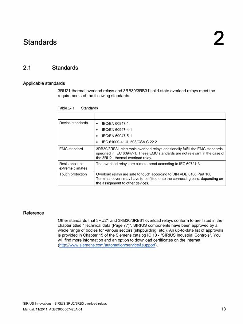
Applicable standards 3RU21 thermal overload relays and 3RB30/3RB31 solid-state overload relays meet the requirements of the following standards:
Table 2- 1 Standards
Device standards • IEC/EN 60947-1
• IEC/EN 60947-4-1 • IEC/EN 60947-5-1 • IEC 61000-4; UL 508/CSA C 22.2
EMC standard 3RB30/3RB31 electronic overload relays additionally fulfill the EMC standards specified in IEC 60947-1. These EMC standards are not relevant in the case of the 3RU21 thermal overload relay.
Resistance to extreme climates
The overload relays are climate-proof according to IEC 60721-3.
Touch protection Overload relays are safe to touch according to DIN VDE 0106 Part 100. Terminal covers may have to be fitted onto the connecting bars, depending on the assignment to other devices.
Reference Other standards that 3RU21 and 3RB30/3RB31 overload relays conform to are listed in the chapter titled "Technical data (Page 77)". SIRIUS components have been approved by a whole range of bodies for various sectors (shipbuilding, etc.). An up-to-date list of approvals is provided in Chapter 15 of the Siemens catalog IC 10 - "SIRIUS Industrial Controls". You will find more information and an option to download certificates on the Internet (http://www.siemens.com/automation/service&support).

Standards 2.1 Standards
SIRIUS Innovations - SIRIUS 3RU2/3RB3 overload relays
14 Manual, 11/2011, A5E03656507420A-01
SIRIUS Innovations - SIRIUS 3RU2/3RB3 overload relays
Manual, 11/2011, A5E03656507420A-01 15
Product description 33.1 Introduction
3RU21 thermal overload relays 3RU21 thermal overload relays up to 40 A have been designed to provide current-dependent protection for loads with normal starting against impermissibly high temperature rises due to overload, phase asymmetry or phase failure.
An overload or phase failure results in an increase of the motor current beyond the set rated motor current. Via heating elements, this current rise increasingly heats up the bimetal strips located inside the device. The deflection of these bimetal strips eventually activates the auxiliary contacts via a release mechanism. The contacts then disconnect the load via a contactor. (The contactor function is not an integral component of the overload relay).
3RB30/3RB31 solid-state overload relays 3RB30/3RB31 solid-state overload relays up to 40 A have been designed to provide current-dependent protection for loads with normal and heavy-duty starting against impermissibly high temperature rises due to overload, phase asymmetry or phase failure.
An overload, phase asymmetry or a phase failure results in an increase of the motor current beyond the set rated motor current.
This current rise is detected by the current transformers integrated in the devices and evaluated by corresponding solid-state circuits which then supply a pulse to the auxiliary contacts. The contacts then disconnect the load via a contactor. (The contactor function is not an integral component of the overload relay).
In addition to current-dependent protection for loads against impermissibly high temperature rise caused by overload, phase asymmetry, and phase failure, 3RB31 solid-state overload relays feature internal ground-fault detection (not possible in conjunction with contactor assemblies for star-delta (wye-delta) start). This provides protection of loads against high-impedance faults to ground caused by damaged insulation, moisture, condensation, etc.
System integration The overload relays have been matched to the contactors in the 3RT2 series both electrically and mechanically and can be integrated in the feeder by means of direct mounting. The 3RU2 thermal overload relays and the 3RB30 and 3RB31 solid-state overload relays are available in two sizes, S00 and S0.
Product description 3.2 Versions
SIRIUS Innovations - SIRIUS 3RU2/3RB3 overload relays
16 Manual, 11/2011, A5E03656507420A-01
Connection systems The overload relays are available with the following connection system options:
● Screw-type connection system
● Spring-loaded connection system
● Ring cable lug connection system (3RU21 only)
Accessories The accessories have been tailored to the overload relays; they can be mounted easily and without the need for tools.
3.2 Versions
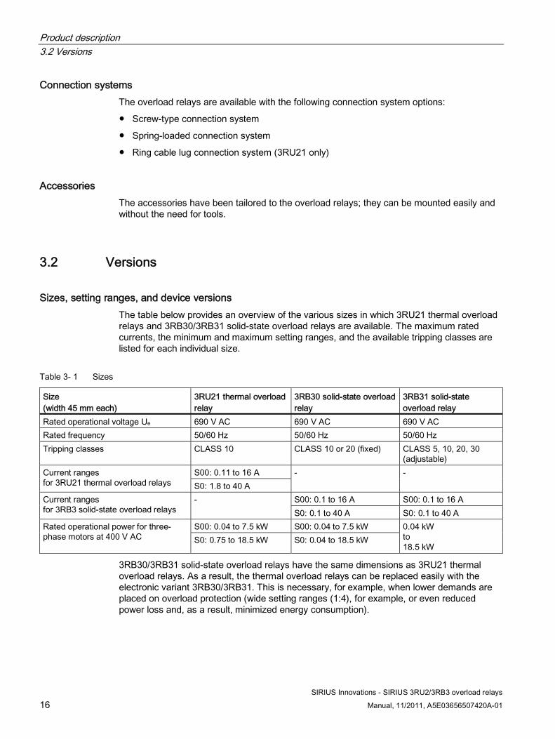
Sizes, setting ranges, and device versions The table below provides an overview of the various sizes in which 3RU21 thermal overload relays and 3RB30/3RB31 solid-state overload relays are available. The maximum rated currents, the minimum and maximum setting ranges, and the available tripping classes are listed for each individual size.
Table 3- 1 Sizes
Size (width 45 mm each)
3RU21 thermal overload relay
3RB30 solid-state overload relay
3RB31 solid-state overload relay
Rated operational voltage Ue 690 V AC 690 V AC 690 V AC Rated frequency 50/60 Hz 50/60 Hz 50/60 Hz Tripping classes CLASS 10 CLASS 10 or 20 (fixed) CLASS 5, 10, 20, 30
(adjustable) S00: 0.11 to 16 A Current ranges
for 3RU21 thermal overload relays S0: 1.8 to 40 A - -
S00: 0.1 to 16 A S00: 0.1 to 16 A Current ranges for 3RB3 solid-state overload relays
- S0: 0.1 to 40 A S0: 0.1 to 40 A
S00: 0.04 to 7.5 kW S00: 0.04 to 7.5 kW Rated operational power for three-phase motors at 400 V AC S0: 0.75 to 18.5 kW S0: 0.04 to 18.5 kW
0.04 kW to 18.5 kW
3RB30/3RB31 solid-state overload relays have the same dimensions as 3RU21 thermal overload relays. As a result, the thermal overload relays can be replaced easily with the electronic variant 3RB30/3RB31. This is necessary, for example, when lower demands are placed on overload protection (wide setting ranges (1:4), for example, or even reduced power loss and, as a result, minimized energy consumption).

Product description 3.3 Applications
SIRIUS Innovations - SIRIUS 3RU2/3RB3 overload relays
Manual, 11/2011, A5E03656507420A-01 17
3.3 Applications
Table 3- 2 Overview of applications
Applications 3RU21 3RB30/3RB31 System protection ✓1) ✓1) Motor protection ✓ ✓ Alternating current, 3-phase ✓ ✓ Alternating current, 1-phase ✓ - DC current ✓ -
1) In the main circuit, the devices provide overload protection for the assigned electrical loads (e.g. motors), feeder cable, and other switching and protection devices in the respective load feeder. The 3 phases have to be under symmetrical load.
3RU21 thermal overload relays 3RU21 thermal overload relays have been designed to protect three-phase loads, DC loads, and single-phase AC loads.
Note Protection of DC loads/single-phase AC loads
If a 3RU21 thermal overload relay is to be used to protect DC loads or single-phase AC loads, all the bimetal strips have to be heated. Therefore, all of the relay's main current paths have to be connected in series.
3RB30/3RB31 solid-state overload relays 3RB30/3RB31 solid-state overload relays are designed to protect three-phase loads in sinusoidal 50/60 Hz voltage supplies.
Note DC loads/Single-phase AC loads
The relay is not suitable for protecting DC loads or single-phase AC loads. In the case of loads with single-pole load, the 3RU21 thermal overload relay or the 3RB22/3RB23 solid-state overload relay (only suitable for the protection of single-phase AC loads) should be used.
Reference More information ... Can be found in the chapter titled ... About overload relay applications Configuration (Page 35)
Product description 3.3 Applications
SIRIUS Innovations - SIRIUS 3RU2/3RB3 overload relays
18 Manual, 11/2011, A5E03656507420A-01
The advantages of load feeders with overload relays Installing load feeders with overload relays (fuses + contactor + overload relay or MSP for starter combinations/circuit breaker (acc. to UL) + contactor + overload relay) has the following advantages over configurations without overload relays (motor starter protector + contactor):
● Overload release and short-circuit release are signaled separately. In the event of a short circuit the fuses or the MSP for starter combinations/circuit breaker (acc. to UL) limit the short-circuit current and in the event of an overload the overload relay disconnects the contactor (and thus the load).
● At voltages higher than 400 V, fuses have a short-circuit breaking capacity of more than 100 kA. Therefore, the fused option comprising fuses + contactor + overload relay is often used in 690 V supplies.
● An automatic RESET can be performed easily in conjunction with an overload relay. As a result, the feeder does not have to be powered back up locally following an overload release.
● Attachable electrical and mechanical RESET modules which are compatible for use with all sizes enable 3RU21 thermal overload relays to be reset remotely. Mechanical RESET modules which are compatible for use with all sizes can also be attached to 3RB30/3RB31 solid-state overload relays. An electrical remote RESET is an integral component of the 3RB31.
● Lengthy start times can be achieved with 3RB30/3RB31 solid-state overload relays.
● 3RB30/3RB31 solid-state overload relays support wide setting ranges of 1:4.
● MSP for starter combinations/circuit breaker (acc. to UL) + contactor + overload relay combinations have the advantage that the load feeder can be isolated easily and all three poles can be disconnected in the event of a short circuit.
Product description 3.4 3RU21 thermal overload relays
SIRIUS Innovations - SIRIUS 3RU2/3RB3 overload relays
Manual, 11/2011, A5E03656507420A-01 19
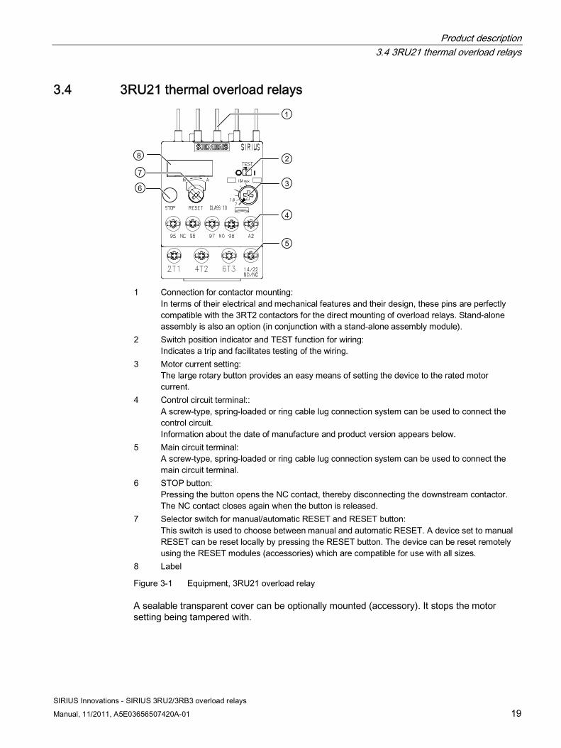
3.4 3RU21 thermal overload relays
1 Connection for contactor mounting:
In terms of their electrical and mechanical features and their design, these pins are perfectly compatible with the 3RT2 contactors for the direct mounting of overload relays. Stand-alone assembly is also an option (in conjunction with a stand-alone assembly module).
2 Switch position indicator and TEST function for wiring: Indicates a trip and facilitates testing of the wiring.
3 Motor current setting: The large rotary button provides an easy means of setting the device to the rated motor current.
4 Control circuit terminal:: A screw-type, spring-loaded or ring cable lug connection system can be used to connect the control circuit. Information about the date of manufacture and product version appears below.
5 Main circuit terminal: A screw-type, spring-loaded or ring cable lug connection system can be used to connect the main circuit terminal.
6 STOP button: Pressing the button opens the NC contact, thereby disconnecting the downstream contactor. The NC contact closes again when the button is released.
7 Selector switch for manual/automatic RESET and RESET button: This switch is used to choose between manual and automatic RESET. A device set to manual RESET can be reset locally by pressing the RESET button. The device can be reset remotely using the RESET modules (accessories) which are compatible for use with all sizes.
8 Label
Figure 3-1 Equipment, 3RU21 overload relay
A sealable transparent cover can be optionally mounted (accessory). It stops the motor setting being tampered with.

Product description 3.4 3RU21 thermal overload relays
SIRIUS Innovations - SIRIUS 3RU2/3RB3 overload relays
20 Manual, 11/2011, A5E03656507420A-01
Auxiliary contacts 3RU21 thermal overload relays are equipped with an NO contact for the "tripped" message and an NC contact for disconnecting the contactor.
Product description 3.5 3RB30/3RB31 solid-state overload relays
SIRIUS Innovations - SIRIUS 3RU2/3RB3 overload relays
Manual, 11/2011, A5E03656507420A-01 21
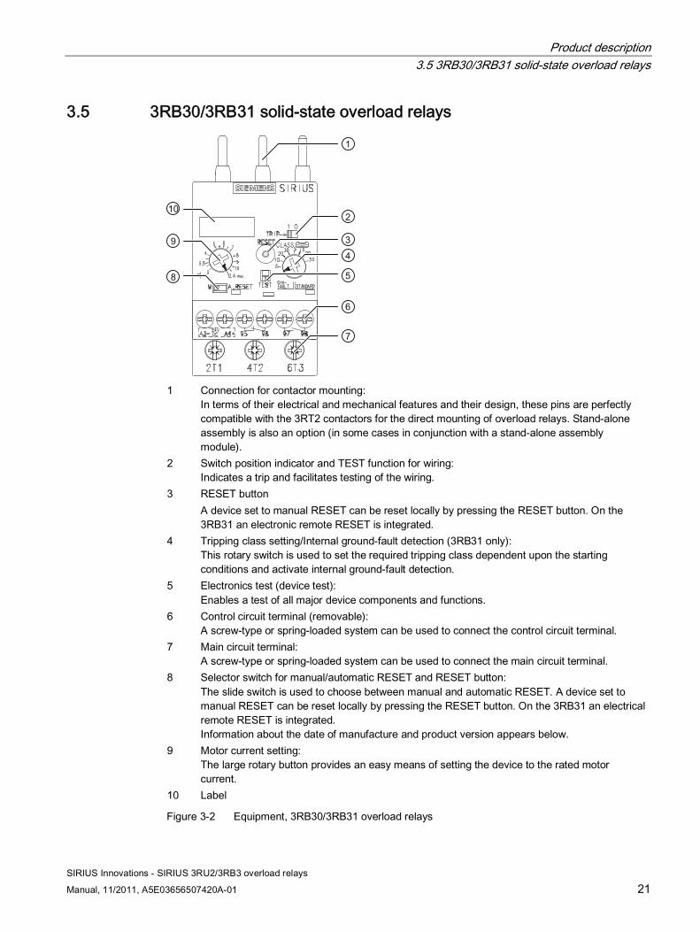
3.5 3RB30/3RB31 solid-state overload relays
1 Connection for contactor mounting:
In terms of their electrical and mechanical features and their design, these pins are perfectly compatible with the 3RT2 contactors for the direct mounting of overload relays. Stand-alone assembly is also an option (in some cases in conjunction with a stand-alone assembly module).
2 Switch position indicator and TEST function for wiring: Indicates a trip and facilitates testing of the wiring.
3 RESET button A device set to manual RESET can be reset locally by pressing the RESET button. On the 3RB31 an electronic remote RESET is integrated.
4 Tripping class setting/Internal ground-fault detection (3RB31 only): This rotary switch is used to set the required tripping class dependent upon the starting conditions and activate internal ground-fault detection.
5 Electronics test (device test): Enables a test of all major device components and functions.
6 Control circuit terminal (removable): A screw-type or spring-loaded system can be used to connect the control circuit terminal.
7 Main circuit terminal: A screw-type or spring-loaded system can be used to connect the main circuit terminal.
8 Selector switch for manual/automatic RESET and RESET button: The slide switch is used to choose between manual and automatic RESET. A device set to manual RESET can be reset locally by pressing the RESET button. On the 3RB31 an electrical remote RESET is integrated. Information about the date of manufacture and product version appears below.
9 Motor current setting: The large rotary button provides an easy means of setting the device to the rated motor current.
10 Label
Figure 3-2 Equipment, 3RB30/3RB31 overload relays

Product description 3.5 3RB30/3RB31 solid-state overload relays
SIRIUS Innovations - SIRIUS 3RU2/3RB3 overload relays
22 Manual, 11/2011, A5E03656507420A-01
A sealable transparent cover can be optionally mounted (accessory). It stops the motor setting being tampered with.
Auxiliary contacts 3RB30/3RB31 solid-state overload relays are equipped with an NO contact for the "tripped" message and an NC contact for disconnecting the contactor.

SIRIUS Innovations - SIRIUS 3RU2/3RB3 overload relays
Manual, 11/2011, A5E03656507420A-01 23
Product combinations 4
Since the products from the innovative SIRIUS modular system are matched to one another both electrically and mechanically, they can be combined quickly and easily.
Reference More information ... Is available in the appendix ... About the possible combinations of standard products from the SIRIUS modular system
"References" under "SIRIUS Innovations manuals (Page 104)"

Product combinations
SIRIUS Innovations - SIRIUS 3RU2/3RB3 overload relays
24 Manual, 11/2011, A5E03656507420A-01
SIRIUS Innovations - SIRIUS 3RU2/3RB3 overload relays
Manual, 11/2011, A5E03656507420A-01 25
Functions 55.1 Protection against overload, phase failure, and phase asymmetry
5.1.1 Functional principle Overload relays are used for the current-dependent protection of electrical consumers (such as motors) against excessive temperature rises, which may be caused by overloading, asymmetrical power consumption, a phase failure in the line supply conductor or a locked rotor.
In the event of an overload, phase asymmetry or a phase failure, or if a rotor locks, the motor current will rise beyond the set rated motor current. This increased current - which, if sustained over a long period, may damage or even destroy the load - is detected by the overload relay and evaluated with the assistance of a thermal motor model.
The overload relays operate according to two different operating principles:
● Thermally with bimetals: 3RU21
● Electronically with current transformers and evaluation electronics: 3RB30 and 3RB31
Functional principle of 3RU21 thermal overload relays The current rise caused by the overload causes increased heat rise affecting the heating elements. The bimetals respond by deflecting, and actuate the auxiliary contacts via the release mechanism.
Functional principle of 3RB30/3RB31 solid-state overload relays The current rise is detected by the integrated current transformers and evaluated by corresponding solid-state circuits which then supply a pulse to the auxiliary contacts. The contactor and the load are disconnected via the auxiliary contacts.
Note Protection of DC loads and single-phase AC loads
Only 3RU21 thermal overload relays can provide an assurance of protecting DC loads and single-phase AC loads against overload.
If a 3RU21 thermal overload relay is to be used to protect DC loads or single-phase AC loads, all the bimetal strips have to be heated. Therefore, all of the relay's main current paths have to be connected in series.
Functions 5.1 Protection against overload, phase failure, and phase asymmetry
SIRIUS Innovations - SIRIUS 3RU2/3RB3 overload relays
26 Manual, 11/2011, A5E03656507420A-01
Phase-failure protection 3RU21 thermal overload relays and 3RB30/3RB31 solid-state overload relays feature phase loss sensitivity (see the chapter titled Tripping characteristics (Page 27)) to minimize load temperature rise in two-phase operation.
5.1.2 Time-delayed overload release The time-delayed overload release is based on a thermal motor model and will trigger a release dependent upon the extent of the overload.
3RU21 thermal overload relays and 3RB30/3RB31 solid-state overload relays compensate temperatures from -40 °C to 60 °C (3RU21) and -25 °C to 60 °C (3RB30/3RB31) according to IEC 60947-4-1.
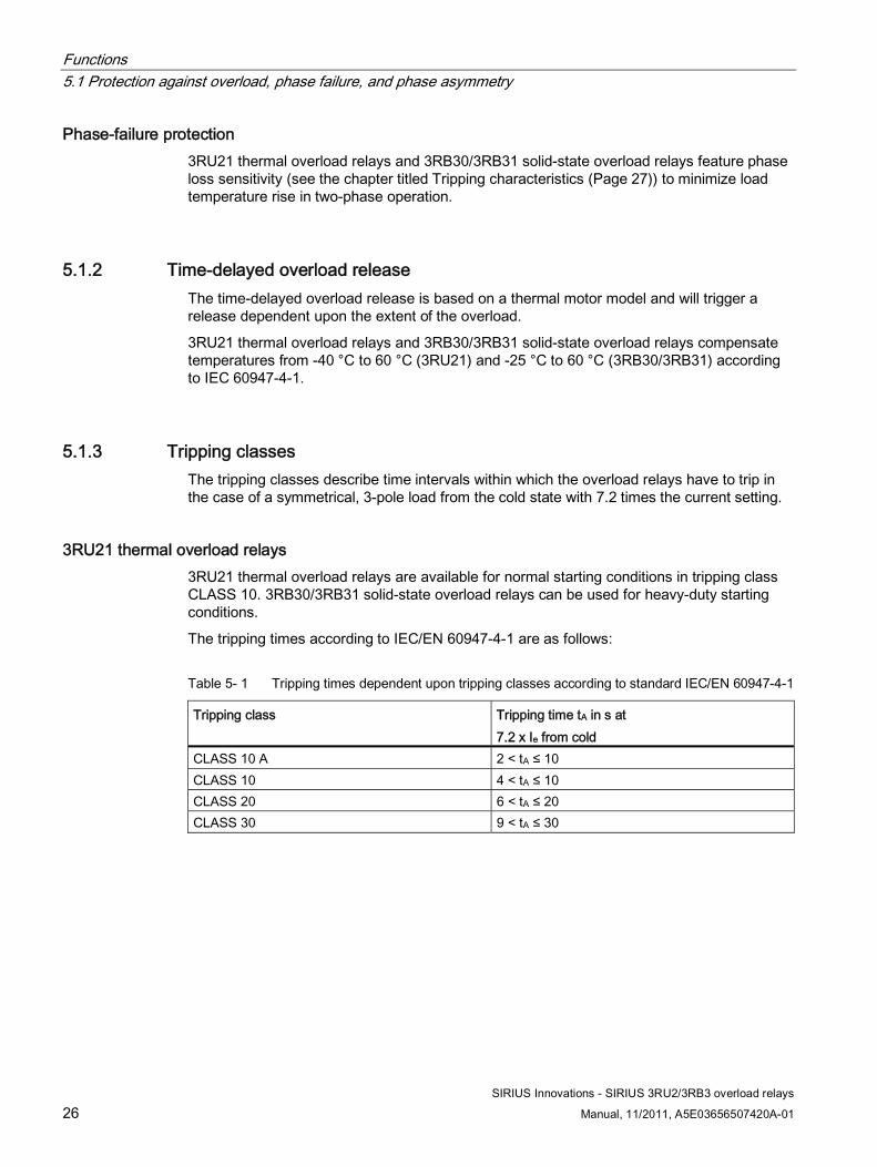
5.1.3 Tripping classes The tripping classes describe time intervals within which the overload relays have to trip in the case of a symmetrical, 3-pole load from the cold state with 7.2 times the current setting.
3RU21 thermal overload relays 3RU21 thermal overload relays are available for normal starting conditions in tripping class CLASS 10. 3RB30/3RB31 solid-state overload relays can be used for heavy-duty starting conditions.
The tripping times according to IEC/EN 60947-4-1 are as follows:
Table 5- 1 Tripping times dependent upon tripping classes according to standard IEC/EN 60947-4-1
Tripping class Tripping time tA in s at 7.2 x Ie from cold
CLASS 10 A 2 < tA ≤ 10 CLASS 10 4 < tA ≤ 10 CLASS 20 6 < tA ≤ 20 CLASS 30 9 < tA ≤ 30
Functions 5.1 Protection against overload, phase failure, and phase asymmetry
SIRIUS Innovations - SIRIUS 3RU2/3RB3 overload relays
Manual, 11/2011, A5E03656507420A-01 27
3RB30/3RB31 solid-state overload relays 3RB30 solid-state overload relays are available for normal starting conditions in tripping class CLASS 10 or for heavy-duty starting conditions in tripping class CLASS 20 (all fixed settings).
3RB31 solid-state relays are suitable for normal and heavy-duty starting conditions. A rotary switch is used to set the required tripping class (CLASS 5, 10, 20 or 30) dependent upon the prevailing starting conditions.
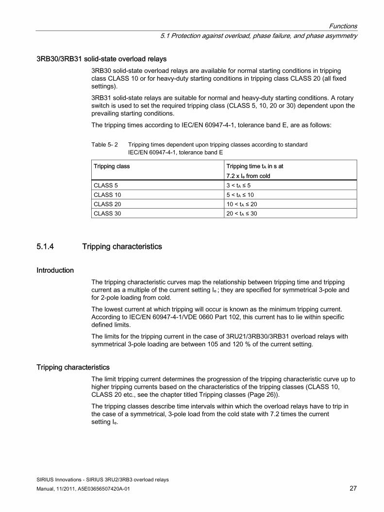
The tripping times according to IEC/EN 60947-4-1, tolerance band E, are as follows:
Table 5- 2 Tripping times dependent upon tripping classes according to standard IEC/EN 60947-4-1, tolerance band E
Tripping class Tripping time tA in s at 7.2 x Ie from cold
CLASS 5 3 < tA ≤ 5 CLASS 10 5 < tA ≤ 10 CLASS 20 10 < tA ≤ 20 CLASS 30 20 < tA ≤ 30
5.1.4 Tripping characteristics
Introduction The tripping characteristic curves map the relationship between tripping time and tripping current as a multiple of the current setting Ie ; they are specified for symmetrical 3-pole and for 2-pole loading from cold.
The lowest current at which tripping will occur is known as the minimum tripping current. According to IEC/EN 60947-4-1/VDE 0660 Part 102, this current has to lie within specific defined limits.
The limits for the tripping current in the case of 3RU21/3RB30/3RB31 overload relays with symmetrical 3-pole loading are between 105 and 120 % of the current setting.
Tripping characteristics The limit tripping current determines the progression of the tripping characteristic curve up to higher tripping currents based on the characteristics of the tripping classes (CLASS 10, CLASS 20 etc., see the chapter titled Tripping classes (Page 26)).
The tripping classes describe time intervals within which the overload relays have to trip in the case of a symmetrical, 3-pole load from the cold state with 7.2 times the current setting Ie.
Functions 5.1 Protection against overload, phase failure, and phase asymmetry
SIRIUS Innovations - SIRIUS 3RU2/3RB3 overload relays
28 Manual, 11/2011, A5E03656507420A-01
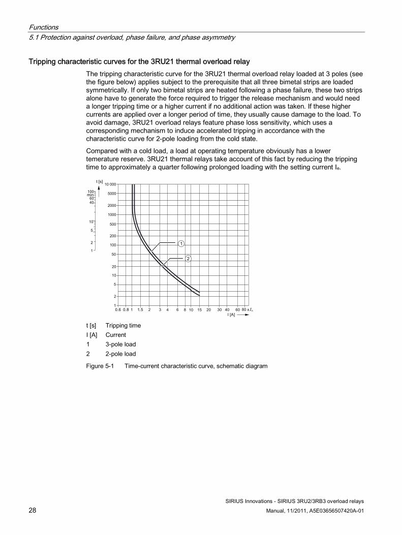
Tripping characteristic curves for the 3RU21 thermal overload relay The tripping characteristic curve for the 3RU21 thermal overload relay loaded at 3 poles (see the figure below) applies subject to the prerequisite that all three bimetal strips are loaded symmetrically. If only two bimetal strips are heated following a phase failure, these two strips alone have to generate the force required to trigger the release mechanism and would need a longer tripping time or a higher current if no additional action was taken. If these higher currents are applied over a longer period of time, they usually cause damage to the load. To avoid damage, 3RU21 overload relays feature phase loss sensitivity, which uses a corresponding mechanism to induce accelerated tripping in accordance with the characteristic curve for 2-pole loading from the cold state.
Compared with a cold load, a load at operating temperature obviously has a lower temerature reserve. 3RU21 thermal relays take account of this fact by reducing the tripping time to approximately a quarter following prolonged loading with the setting current Ie.
1
2
t [s] Tripping time I [A] Current 1 3-pole load 2 2-pole load
Figure 5-1 Time-current characteristic curve, schematic diagram
Functions 5.1 Protection against overload, phase failure, and phase asymmetry
SIRIUS Innovations - SIRIUS 3RU2/3RB3 overload relays
Manual, 11/2011, A5E03656507420A-01 29
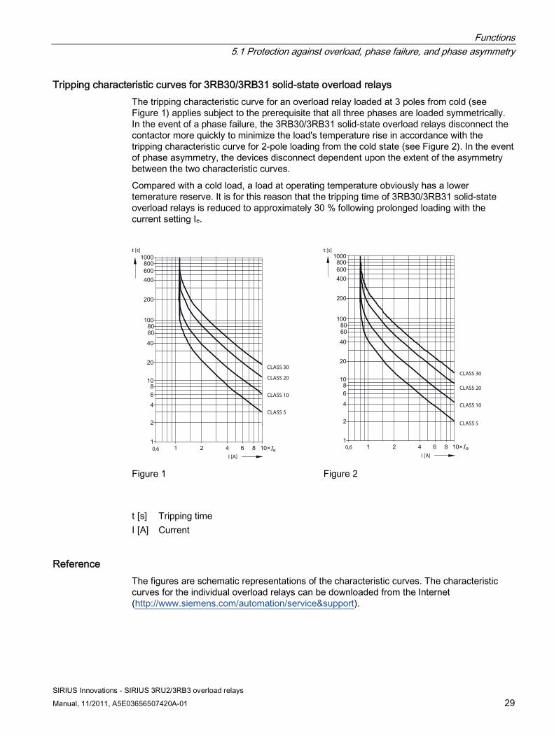
Tripping characteristic curves for 3RB30/3RB31 solid-state overload relays The tripping characteristic curve for an overload relay loaded at 3 poles from cold (see Figure 1) applies subject to the prerequisite that all three phases are loaded symmetrically. In the event of a phase failure, the 3RB30/3RB31 solid-state overload relays disconnect the contactor more quickly to minimize the load's temperature rise in accordance with the tripping characteristic curve for 2-pole loading from the cold state (see Figure 2). In the event of phase asymmetry, the devices disconnect dependent upon the extent of the asymmetry between the two characteristic curves.
Compared with a cold load, a load at operating temperature obviously has a lower temerature reserve. It is for this reason that the tripping time of 3RB30/3RB31 solid-state overload relays is reduced to approximately 30 % following prolonged loading with the current setting Ie.
t [s]
I [A]
CLASS 30
CLASS 5
CLASS 10
CLASS 20
0,6
t [s]
I [A]
CLASS 30
CLASS 5
CLASS 10
CLASS 20
0,6
Figure 1 Figure 2
t [s] Tripping time I [A] Current
Reference The figures are schematic representations of the characteristic curves. The characteristic curves for the individual overload relays can be downloaded from the Internet (http://www.siemens.com/automation/service&support).
Functions 5.2 Ground fault protection in the case of the 3RB31
SIRIUS Innovations - SIRIUS 3RU2/3RB3 overload relays
30 Manual, 11/2011, A5E03656507420A-01
5.2 Ground fault protection in the case of the 3RB31
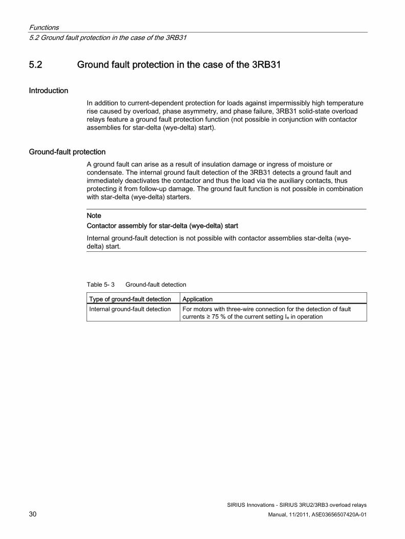
Introduction In addition to current-dependent protection for loads against impermissibly high temperature rise caused by overload, phase asymmetry, and phase failure, 3RB31 solid-state overload relays feature a ground fault protection function (not possible in conjunction with contactor assemblies for star-delta (wye-delta) start).
Ground-fault protection A ground fault can arise as a result of insulation damage or ingress of moisture or condensate. The internal ground fault detection of the 3RB31 detects a ground fault and immediately deactivates the contactor and thus the load via the auxiliary contacts, thus protecting it from follow-up damage. The ground fault function is not possible in combination with star-delta (wye-delta) starters.
Note Contactor assembly for star-delta (wye-delta) start
Internal ground-fault detection is not possible with contactor assemblies star-delta (wye-delta) start.
Table 5- 3 Ground-fault detection
Type of ground-fault detection Application Internal ground-fault detection For motors with three-wire connection for the detection of fault
currents ≥ 75 % of the current setting Ie in operation
Functions 5.3 Auxiliary contacts
SIRIUS Innovations - SIRIUS 3RU2/3RB3 overload relays
Manual, 11/2011, A5E03656507420A-01 31
5.3 Auxiliary contacts
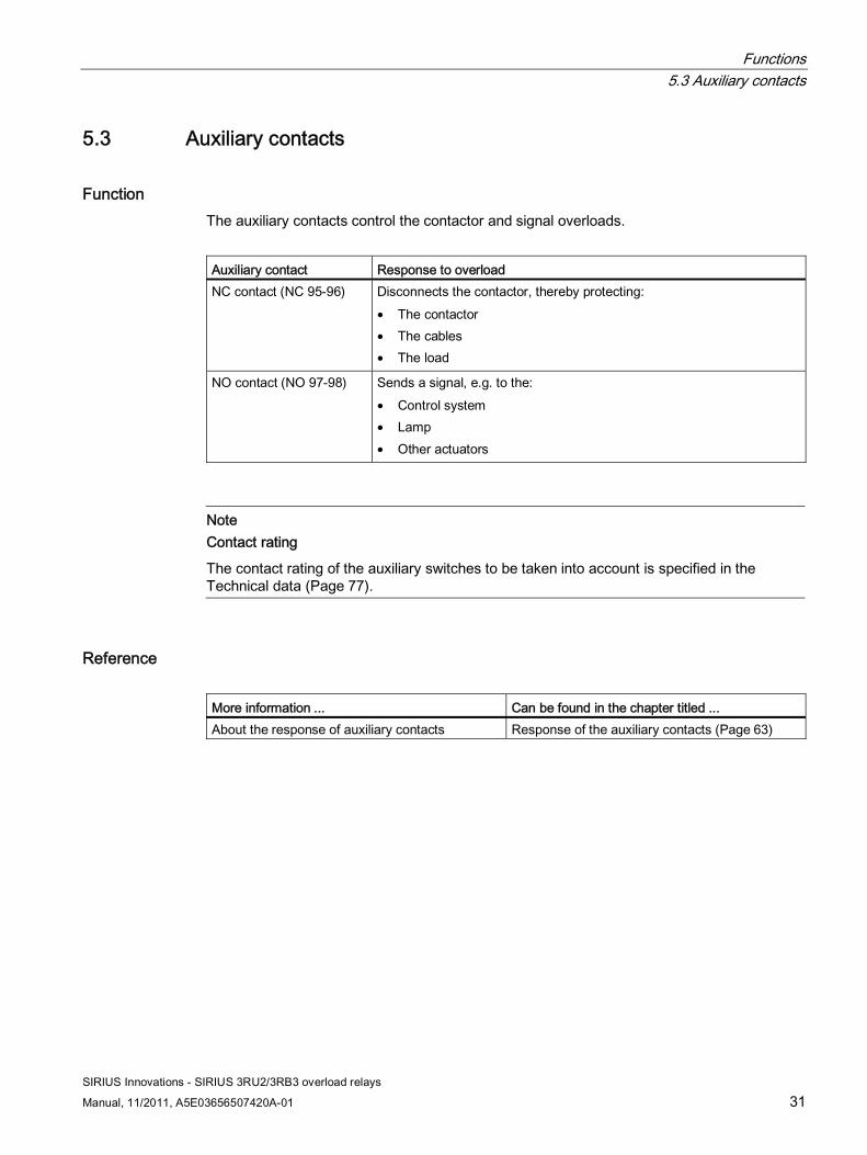
Function The auxiliary contacts control the contactor and signal overloads.
Auxiliary contact Response to overload NC contact (NC 95-96) Disconnects the contactor, thereby protecting:
• The contactor • The cables • The load
NO contact (NO 97-98) Sends a signal, e.g. to the: • Control system • Lamp • Other actuators
Note Contact rating
The contact rating of the auxiliary switches to be taken into account is specified in the Technical data (Page 77).
Reference More information ... Can be found in the chapter titled ... About the response of auxiliary contacts Response of the auxiliary contacts (Page 63)

Functions 5.4 Indication of the operating state
SIRIUS Innovations - SIRIUS 3RU2/3RB3 overload relays
32 Manual, 11/2011, A5E03656507420A-01
5.4 Indication of the operating state The prevailing operating state of the 3RU21/3RB30/3RB31 relays is indicated by the position of the marker on the "TEST function/Switch position indicator" slide.
If the relays are operating without errors, the slide marker will be set to "I". When a device trips, the slide marker moves to "0". An overload relay can trip for the following reasons:
● Overload,
● Phase asymmetry,
● Phase failure, or
● Ground fault (3RB31)
● Internal error (3RB30/3RB31)
Resetting The relay is reset manually or automatically after a recovery time has elapsed.
Reference Additional information... Can be found in the chapter titled... About resetting RESET after release (Page 59)
5.5 Self-monitoring (3RB30/3RB31 only) 3RB30/3RB31 solid-state overload relays constantly monitor their ability to operate (self-monitoring) and trip in the event of an internal error.
In such cases you need to contact Technical Assistance on the Internet (http://www.siemens.com/automation/service&support)
Functions 5.6 Additional functions
SIRIUS Innovations - SIRIUS 3RU2/3RB3 overload relays
Manual, 11/2011, A5E03656507420A-01 33
5.6 Additional functions
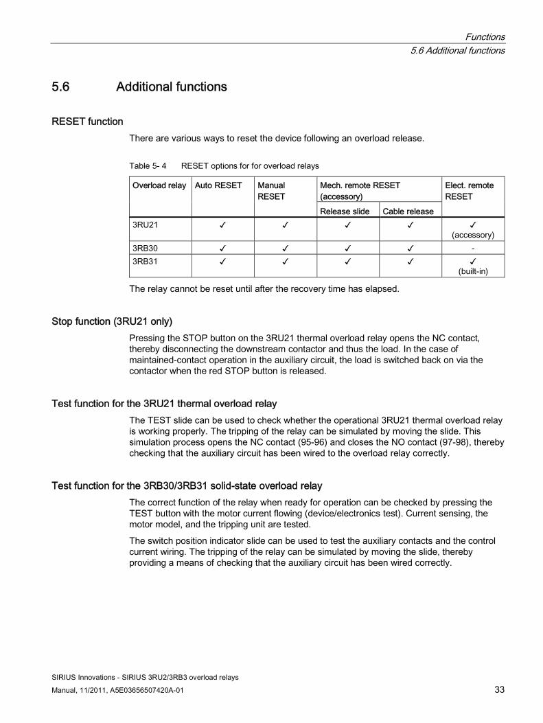
RESET function There are various ways to reset the device following an overload release.
Table 5- 4 RESET options for for overload relays
Mech. remote RESET (accessory)
Overload relay Auto RESET Manual RESET
Release slide Cable release
Elect. remote RESET
3RU21 ✓ ✓ ✓ ✓ ✓ (accessory)
3RB30 ✓ ✓ ✓ ✓ - 3RB31 ✓ ✓ ✓ ✓ ✓
(built-in)
The relay cannot be reset until after the recovery time has elapsed.
Stop function (3RU21 only) Pressing the STOP button on the 3RU21 thermal overload relay opens the NC contact, thereby disconnecting the downstream contactor and thus the load. In the case of maintained-contact operation in the auxiliary circuit, the load is switched back on via the contactor when the red STOP button is released.
Test function for the 3RU21 thermal overload relay The TEST slide can be used to check whether the operational 3RU21 thermal overload relay is working properly. The tripping of the relay can be simulated by moving the slide. This simulation process opens the NC contact (95-96) and closes the NO contact (97-98), thereby checking that the auxiliary circuit has been wired to the overload relay correctly.
Test function for the 3RB30/3RB31 solid-state overload relay The correct function of the relay when ready for operation can be checked by pressing the TEST button with the motor current flowing (device/electronics test). Current sensing, the motor model, and the tripping unit are tested.
The switch position indicator slide can be used to test the auxiliary contacts and the control current wiring. The tripping of the relay can be simulated by moving the slide, thereby providing a means of checking that the auxiliary circuit has been wired correctly.

Functions 5.6 Additional functions
SIRIUS Innovations - SIRIUS 3RU2/3RB3 overload relays
34 Manual, 11/2011, A5E03656507420A-01
Reference More information ... Can be found in the chapter titled ... About the RESET function RESET after release (Page 59) About the test function TEST function (Page 61)
SIRIUS Innovations - SIRIUS 3RU2/3RB3 overload relays
Manual, 11/2011, A5E03656507420A-01 35
Configuration 66.1 SIRIUS Innovations system configurator
Reference To assist you with configuration, the "SIRIUS Innovations system configurator" is at your disposal on the Internet. Here, you can gather together all necessary products before the actual configuration process and you can realize complete projects virtually.
You can find the "SIRIUS Innovations system configurator" on the Internet (www.siemens.com/industrial-controls/configurators).
Configuration 6.2 Overload relays in motor feeders
SIRIUS Innovations - SIRIUS 3RU2/3RB3 overload relays
36 Manual, 11/2011, A5E03656507420A-01
6.2 Overload relays in motor feeders
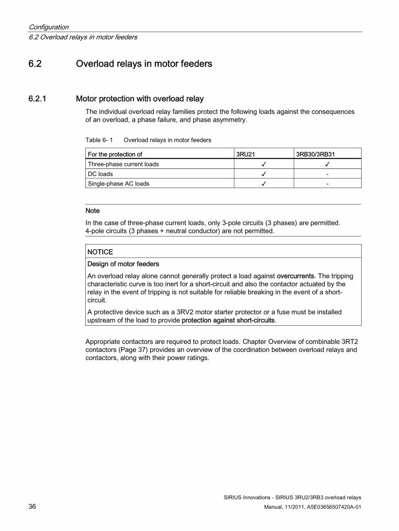
6.2.1 Motor protection with overload relay The individual overload relay families protect the following loads against the consequences of an overload, a phase failure, and phase asymmetry.
Table 6- 1 Overload relays in motor feeders
For the protection of 3RU21 3RB30/3RB31 Three-phase current loads ✓ ✓ DC loads ✓ - Single-phase AC loads ✓ -
Note
In the case of three-phase current loads, only 3-pole circuits (3 phases) are permitted. 4-pole circuits (3 phases + neutral conductor) are not permitted.
NOTICE Design of motor feeders
An overload relay alone cannot generally protect a load against overcurrents. The tripping characteristic curve is too inert for a short-circuit and also the contactor actuated by the relay in the event of tripping is not suitable for reliable breaking in the event of a short-circuit.
A protective device such as a 3RV2 motor starter protector or a fuse must be installed upstream of the load to provide protection against short-circuits.
Appropriate contactors are required to protect loads. Chapter Overview of combinable 3RT2 contactors (Page 37) provides an overview of the coordination between overload relays and contactors, along with their power ratings.
Configuration 6.2 Overload relays in motor feeders
SIRIUS Innovations - SIRIUS 3RU2/3RB3 overload relays
Manual, 11/2011, A5E03656507420A-01 37
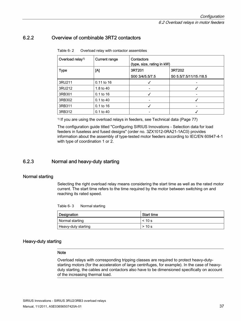
6.2.2 Overview of combinable 3RT2 contactors
Table 6- 2 Overload relay with contactor assemblies
Overload relay1) Current range Contactors (type, size, rating in kW)
Type [A] 3RT201 S00 3/4/5.5/7.5
3RT202 S0 5.5/7.5/11/15 /18.5
3RU211 0.11 to 16 ✓ - 3RU212 1.8 to 40 - ✓ 3RB301 0.1 to 16 ✓ - 3RB302 0.1 to 40 - ✓ 3RB311 0.1 to 16 ✓ - 3RB312 0.1 to 40 - ✓
1) If you are using the overload relays in feeders, see Technical data (Page 77)
The configuration guide titled "Configuring SIRIUS Innovations - Selection data for load feeders in fuseless and fused designs" (order no. 3ZX1012-0RA21-1AC0) provides information about the assembly of type-tested motor feeders according to IEC/EN 60947-4-1 with type of coordination 1 or 2.
6.2.3 Normal and heavy-duty starting
Normal starting Selecting the right overload relay means considering the start time as well as the rated motor current. The start time refers to the time required by the motor between switching on and reaching its rated speed.
Table 6- 3 Normal starting
Designation Start time Normal starting < 10 s Heavy-duty starting > 10 s
Heavy-duty starting
Note
Overload relays with corresponding tripping classes are required to protect heavy-duty-starting motors (for the acceleration of large centrifuges, for example). In the case of heavy-duty starting, the cables and contactors also have to be dimensioned specifically on account of the increasing thermal load.
Configuration 6.2 Overload relays in motor feeders
SIRIUS Innovations - SIRIUS 3RU2/3RB3 overload relays
38 Manual, 11/2011, A5E03656507420A-01
6.2.4 Contactor assembly for star-delta (wye-delta) start
Overload relays in contactor assemblies for star-delta (wye-delta) start When using overload relays in conjunction with contactor assemblies for star-delta (wye-delta) start, you need to bear in mind that only 1/√3 times the motor current flows through the line contactor. An overload relay mounted onto a line contactor has to be set to this 0.58-times motor current.
NOTICE Internal ground-fault detection on the 3RB31
If you are using the 3RB31 solid-state overload relay in conjunction with contactor assemblies for star-delta (wye-delta) start, internal ground-fault detection must not be activated due to the occurrence of transient current peaks when switching over from star (wye) to delta operation. These can cause ground-fault monitoring to respond.
6.2.5 Operation with frequency converters
3RU21 thermal overload relays 3RU21 thermal overload relays are suitable for operation with frequency converters. Depending on the frequency of the converter, eddy current and skin effects that occur mean that in some cases, a current higher than the motor current has to be set.
3RB30/3RB31 solid-state overload relays 3RB30/3RB31 solid-state overload relays are suitable for frequencies of 50/60 Hz and their associated harmonics. This makes it possible to use a 3RB30/3RB31 on the input side of the frequency converter. If motor protection is required on the outgoing side of the frequency converter, we recommend the 3RN thermistor motor protection devices or 3RU21 thermal overload relays.
Reference More information ... Is available in the appendix ... About the currents to be set "References" under SIRIUS Innovations manuals
(Page 104) in the "SIRIUS Innovations - SIRIUS 3RV2 motor starter protectors" manual
Configuration 6.3 Short-circuit protection
SIRIUS Innovations - SIRIUS 3RU2/3RB3 overload relays
Manual, 11/2011, A5E03656507420A-01 39
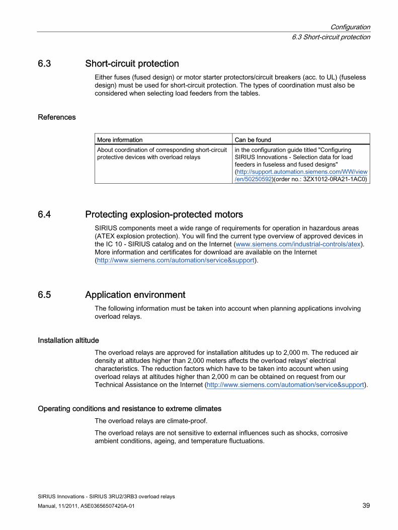
6.3 Short-circuit protection Either fuses (fused design) or motor starter protectors/circuit breakers (acc. to UL) (fuseless design) must be used for short-circuit protection. The types of coordination must also be considered when selecting load feeders from the tables.
References More information Can be found About coordination of corresponding short-circuit protective devices with overload relays
in the configuration guide titled "Configuring SIRIUS Innovations - Selection data for load feeders in fuseless and fused designs" (http://support.automation.siemens.com/WW/view/en/50250592)(order no.: 3ZX1012-0RA21-1AC0)
6.4 Protecting explosion-protected motors SIRIUS components meet a wide range of requirements for operation in hazardous areas (ATEX explosion protection). You will find the current type overview of approved devices in the IC 10 - SIRIUS catalog and on the Internet (www.siemens.com/industrial-controls/atex). More information and certificates for download are available on the Internet (http://www.siemens.com/automation/service&support).
6.5 Application environment The following information must be taken into account when planning applications involving overload relays.
Installation altitude The overload relays are approved for installation altitudes up to 2,000 m. The reduced air density at altitudes higher than 2,000 meters affects the overload relays' electrical characteristics. The reduction factors which have to be taken into account when using overload relays at altitudes higher than 2,000 m can be obtained on request from our Technical Assistance on the Internet (http://www.siemens.com/automation/service&support).
Operating conditions and resistance to extreme climates The overload relays are climate-proof.
The overload relays are not sensitive to external influences such as shocks, corrosive ambient conditions, ageing, and temperature fluctuations.
Configuration 6.5 Application environment
SIRIUS Innovations - SIRIUS 3RU2/3RB3 overload relays
40 Manual, 11/2011, A5E03656507420A-01
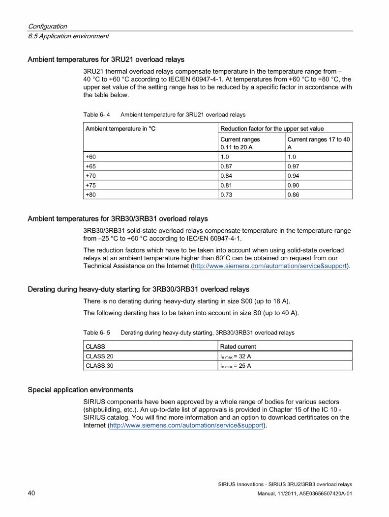
Ambient temperatures for 3RU21 overload relays 3RU21 thermal overload relays compensate temperature in the temperature range from –40 °C to +60 °C according to IEC/EN 60947-4-1. At temperatures from +60 °C to +80 °C, the upper set value of the setting range has to be reduced by a specific factor in accordance with the table below.
Table 6- 4 Ambient temperature for 3RU21 overload relays
Reduction factor for the upper set value Ambient temperature in °C
Current ranges 0.11 to 20 A
Current ranges 17 to 40 A
+60 1.0 1.0 +65 0.87 0.97 +70 0.84 0.94 +75 0.81 0.90 +80 0.73 0.86
Ambient temperatures for 3RB30/3RB31 overload relays 3RB30/3RB31 solid-state overload relays compensate temperature in the temperature range from –25 °C to +60 °C according to IEC/EN 60947-4-1.
The reduction factors which have to be taken into account when using solid-state overload relays at an ambient temperature higher than 60°C can be obtained on request from our Technical Assistance on the Internet (http://www.siemens.com/automation/service&support).
Derating during heavy-duty starting for 3RB30/3RB31 overload relays There is no derating during heavy-duty starting in size S00 (up to 16 A).
The following derating has to be taken into account in size S0 (up to 40 A).
Table 6- 5 Derating during heavy-duty starting, 3RB30/3RB31 overload relays
CLASS Rated current CLASS 20 Ie max = 32 A CLASS 30 Ie max = 25 A
Special application environments SIRIUS components have been approved by a whole range of bodies for various sectors (shipbuilding, etc.). An up-to-date list of approvals is provided in Chapter 15 of the IC 10 - SIRIUS catalog. You will find more information and an option to download certificates on the Internet (http://www.siemens.com/automation/service&support).
SIRIUS Innovations - SIRIUS 3RU2/3RB3 overload relays
Manual, 11/2011, A5E03656507420A-01 41
Mounting 77.1 Mounting options
Mounting options for the 3RU21, 3RB30 and 3RB31 The 3RU21 thermal overload relays and the 3R30 and 3RB31 solid-state overload relays are matched to the 3RT2 contactors. As a result, direct mounting can be achieved easily. Alternatively, the devices are suitable for stand-alone assembly.
7.2 Minimum clearances and mounting position
Minimum clearance A minimum lateral clearance of > 6 mm must be maintained from grounded parts.
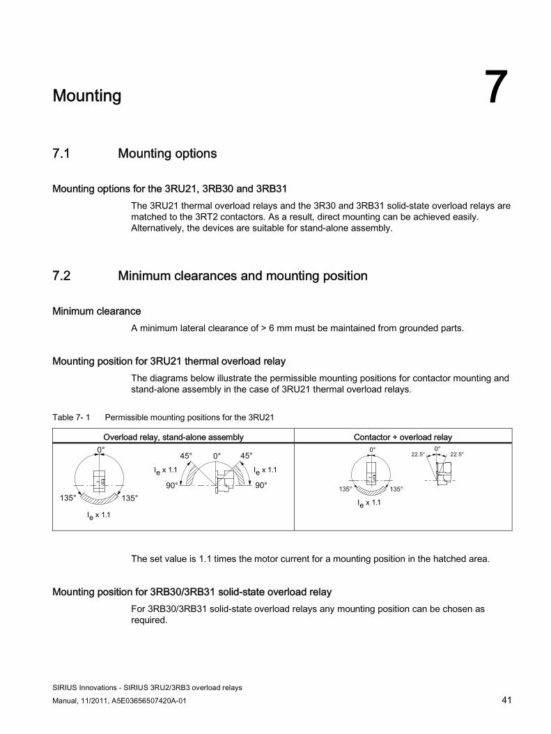
Mounting position for 3RU21 thermal overload relay The diagrams below illustrate the permissible mounting positions for contactor mounting and stand-alone assembly in the case of 3RU21 thermal overload relays.
Table 7- 1 Permissible mounting positions for the 3RU21
Overload relay, stand-alone assembly Contactor + overload relay
The set value is 1.1 times the motor current for a mounting position in the hatched area.
Mounting position for 3RB30/3RB31 solid-state overload relay For 3RB30/3RB31 solid-state overload relays any mounting position can be chosen as required.
Mounting 7.3 Mounting/Disassembly
SIRIUS Innovations - SIRIUS 3RU2/3RB3 overload relays
42 Manual, 11/2011, A5E03656507420A-01
7.3 Mounting/Disassembly
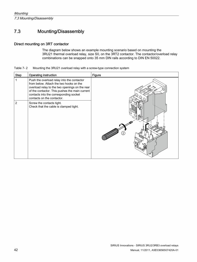
Direct mounting on 3RT contactor The diagram below shows an example mounting scenario based on mounting the 3RU21 thermal overload relay, size S0, on the 3RT2 contactor. The contactor/overload relay combinations can be snapped onto 35 mm DIN rails according to DIN EN 50022.
Table 7- 2 Mounting the 3RU21 overload relay with a screw-type connection system
Step Operating instruction Figure 1 Push the overload relay into the contactor
from below. Attach the two hooks on the overload relay to the two openings on the rear of the contactor. This pushes the main current contacts into the corresponding socket contacts on the contactor.
2 Screw the contacts tight. Check that the cable is clamped tight.
Mounting 7.3 Mounting/Disassembly
SIRIUS Innovations - SIRIUS 3RU2/3RB3 overload relays
Manual, 11/2011, A5E03656507420A-01 43
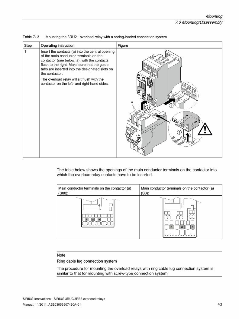
Table 7- 3 Mounting the 3RU21 overload relay with a spring-loaded connection system
Step Operating instruction Figure 1 Insert the contacts (a) into the central opening
of the main conductor terminals on the contactor (see below, a), with the contacts flush to the right. Make sure that the guide tabs are inserted into the designated slots on the contactor. The overload relay will sit flush with the contactor on the left- and right-hand sides.
The table below shows the openings of the main conductor terminals on the contactor into which the overload relay contacts have to be inserted.
Main conductor terminals on the contactor (a) (S00):
Main conductor terminals on the contactor (a) (S0):
Note Ring cable lug connection system
The procedure for mounting the overload relays with ring cable lug connection system is similar to that for mounting with screw-type connection system.
Mounting 7.3 Mounting/Disassembly
SIRIUS Innovations - SIRIUS 3RU2/3RB3 overload relays
44 Manual, 11/2011, A5E03656507420A-01
Mounting on mounting plate Screw mounting on a mounting plate is an alternative option to DIN rail mounting. For screw mounting, the contactor first has to be fastened with screws and then the overload relay mounted on the top of the contactor as shown in the figures.
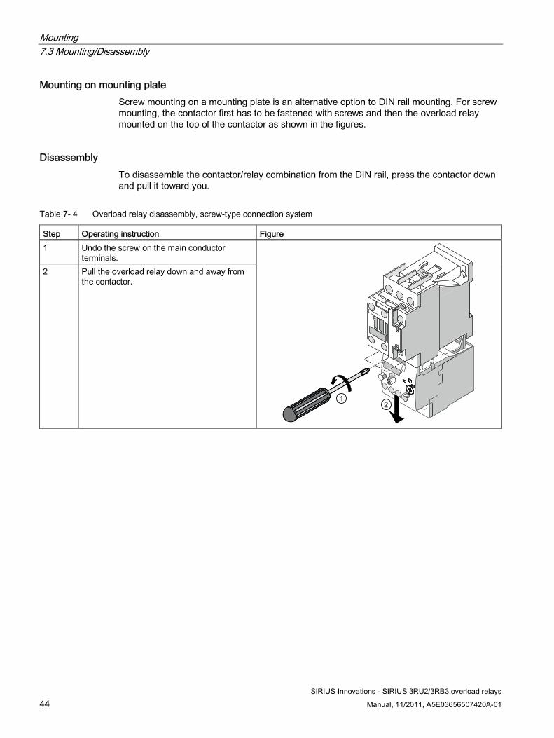
Disassembly To disassemble the contactor/relay combination from the DIN rail, press the contactor down and pull it toward you.
Table 7- 4 Overload relay disassembly, screw-type connection system
Step Operating instruction Figure 1 Undo the screw on the main conductor
terminals. 2 Pull the overload relay down and away from
the contactor.
Mounting 7.3 Mounting/Disassembly
SIRIUS Innovations - SIRIUS 3RU2/3RB3 overload relays
Manual, 11/2011, A5E03656507420A-01 45
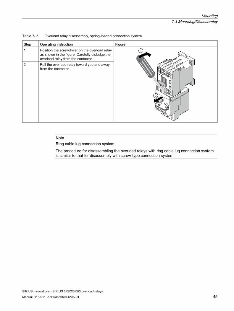
Table 7- 5 Overload relay disassembly, spring-loaded connection system
Step Operating instruction Figure 1 Position the screwdriver on the overload relay
as shown in the figure. Carefully dislodge the overload relay from the contactor.
2 Pull the overload relay toward you and away from the contactor.
Note Ring cable lug connection system
The procedure for disassembling the overload relays with ring cable lug connection system is similar to that for disassembly with screw-type connection system.

Mounting 7.3 Mounting/Disassembly
SIRIUS Innovations - SIRIUS 3RU2/3RB3 overload relays
46 Manual, 11/2011, A5E03656507420A-01
SIRIUS Innovations - SIRIUS 3RU2/3RB3 overload relays
Manual, 11/2011, A5E03656507420A-01 47
Connection 8
Connection types The overload relays are available with the following connection types for the main and auxiliary current paths:
● Screw-type connection system
● Spring-loaded connection system
● Ring cable lug connection system (3RU21 only) with optional terminal covers (accessories)
Conductor cross-sections The conductor cross-sections of the devices in the SIRIUS modular system are matched to one another on a size-specific basis.
Coil repeat and auxiliary switch repeat terminal In the case of size S00 3RU21 thermal overload relays and 3RB30/3RB31 solid-state overload relays, direct contactor mounting involves feed-through of the auxiliary switch and coil terminals A2 on the contactor. This makes wiring much easier.
Touch protection Please observe the information in the chapter titled Technical data (Page 77) with regard to touch protection for 3RU21 thermal overload relays and 3RB30/3RB31 solid-state overload relays (according to IEC 61140). Devices with screw-type and spring-loaded connection systems are finger-safe. To achieve finger safety in the case of ring cable lug connection systems, the addition of terminal covers (accessories) is required.
Reference More information ... Can be found ... On the conductor cross-sections of the devices of the SIRIUS modular system
in the appendix entitled "References" under SIRIUS Innovations manuals (Page 104) in the "SIRIUS Innovations - System Overview" manual
With regard to touch protection for 3RU21 thermal overload relays and 3RB30/3RB31 solid-state overload relays
In the chapter titled Technical data (Page 77)
Connection 8.1 Connection of 3RU21 overload relay
SIRIUS Innovations - SIRIUS 3RU2/3RB3 overload relays
48 Manual, 11/2011, A5E03656507420A-01
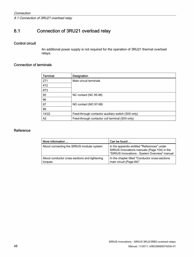
8.1 Connection of 3RU21 overload relay
Control circuit An additional power supply is not required for the operation of 3RU21 thermal overload relays.
Connection of terminals Terminal Designation 2T1 4T2 6T3
Main circuit terminals
95 96
NC contact (NC 95-96)
97 98
NO contact (NO 97-98)
14/22 Feed-through contactor auxiliary switch (S00 only) A2 Feed-through contactor coil terminal (S00 only)
Reference More information ... Can be found ... About connecting the SIRIUS modular system in the appendix entitled "References" under
SIRIUS Innovations manuals (Page 104) in the "SIRIUS Innovations - System Overview" manual
About conductor cross-sections and tightening torques
In the chapter titled "Conductor cross-sections main circuit (Page 84)"
Connection 8.2 Connection of 3RB30/3RB31 overload relays
SIRIUS Innovations - SIRIUS 3RU2/3RB3 overload relays
Manual, 11/2011, A5E03656507420A-01 49
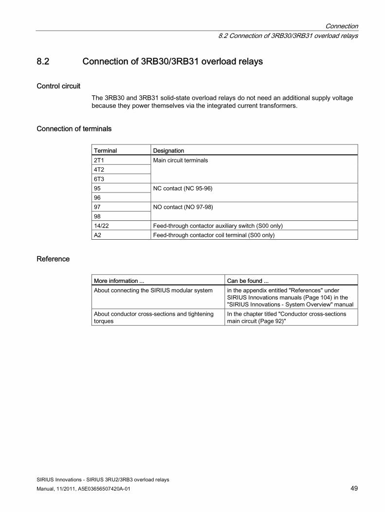
8.2 Connection of 3RB30/3RB31 overload relays
Control circuit The 3RB30 and 3RB31 solid-state overload relays do not need an additional supply voltage because they power themselves via the integrated current transformers.
Connection of terminals Terminal Designation 2T1 4T2 6T3
Main circuit terminals
95 96
NC contact (NC 95-96)
97 98
NO contact (NO 97-98)
14/22 Feed-through contactor auxiliary switch (S00 only) A2 Feed-through contactor coil terminal (S00 only)
Reference More information ... Can be found ... About connecting the SIRIUS modular system in the appendix entitled "References" under
SIRIUS Innovations manuals (Page 104) in the "SIRIUS Innovations - System Overview" manual
About conductor cross-sections and tightening torques
In the chapter titled "Conductor cross-sections main circuit (Page 92)"
Connection 8.3 Connection cross-sections
SIRIUS Innovations - SIRIUS 3RU2/3RB3 overload relays
50 Manual, 11/2011, A5E03656507420A-01
8.3 Connection cross-sections
8.3.1 Conductor cross-sections for screw-type connection systems
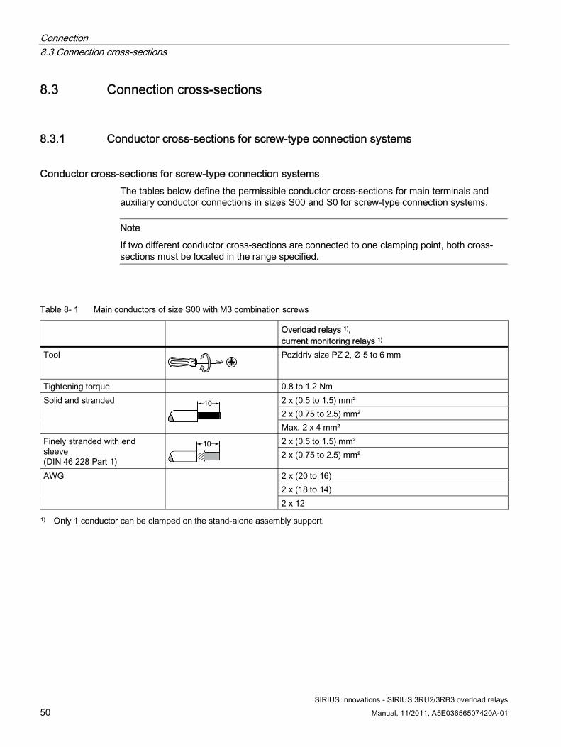
Conductor cross-sections for screw-type connection systems The tables below define the permissible conductor cross-sections for main terminals and auxiliary conductor connections in sizes S00 and S0 for screw-type connection systems.
Note
If two different conductor cross-sections are connected to one clamping point, both cross-sections must be located in the range specified.
Table 8- 1 Main conductors of size S00 with M3 combination screws
Overload relays 1), current monitoring relays 1)
Tool
Pozidriv size PZ 2, Ø 5 to 6 mm
Tightening torque 0.8 to 1.2 Nm 2 x (0.5 to 1.5) mm² 2 x (0.75 to 2.5) mm²
Solid and stranded
Max. 2 x 4 mm² 2 x (0.5 to 1.5) mm² Finely stranded with end
sleeve (DIN 46 228 Part 1) 2 x (0.75 to 2.5) mm²
2 x (20 to 16) 2 x (18 to 14)
AWG
2 x 12
1) Only 1 conductor can be clamped on the stand-alone assembly support.

Connection 8.3 Connection cross-sections
SIRIUS Innovations - SIRIUS 3RU2/3RB3 overload relays
Manual, 11/2011, A5E03656507420A-01 51
Table 8- 2 Main conductors of size S0 with M4 combination screws
Overload relays 1), current monitoring relays 1)
Tool
Pozidriv size PZ 2, Ø 5 to 6 mm
Tightening torque 2.0 to 2.5 Nm 2 x (1.0 to 2.5) mm² Solid and stranded
2 x (2.5 to 10) mm²
2 x (1 to 2.5) mm² 2 x (2.5 to 6) mm²
Finely stranded with end sleeve (DIN 46 228 Part 1)
Max. 1 x 10 mm² 2 x (16 to 12) AWG 2 x (14 to 8)
1) Only 1 conductor can be clamped on the stand-alone assembly support.
Table 8- 3 Auxiliary conductors of size S00/S0 with M3 combination screws
Overload relay Tool
Pozidriv size PZ 2, Ø 5 to 6 mm
Tightening torque 0.8 to 1.2 Nm 2 x (0.5 to 1.5) mm² 2 x (0.75 to 2.5) mm²
Solid and stranded
2 x (0.5 to 1.5) mm² Finely stranded with end
sleeve (DIN 46 228 Part 1) 2 x (0.75 to 2.5) mm²
2 x (20 to 16) 2 x (18 to 14)
AWG

Connection 8.3 Connection cross-sections
SIRIUS Innovations - SIRIUS 3RU2/3RB3 overload relays
52 Manual, 11/2011, A5E03656507420A-01
Table 8- 4 Removable terminal
Removable terminal Tool
Pozidriv size PZ 2, Ø 6 mm
Tightening torque 0.8 to 1.2 Nm 1 x (0.5 to 4) mm² Solid and stranded
2 x (0.5 to 2.5) mm²
1 x (0.5 to 2.5) mm² Finely stranded with end sleeve
2 x (0.5 to 1.5) mm²
AWG 2 x (20 to 14)
8.3.2 Conductor cross-sections for spring-loaded connection systems
Conductor cross-sections for spring-loaded connection systems The tables below define the permissible conductor cross-sections for main terminals and auxiliary conductor connections in sizes S00 and S0 for spring-loaded connection systems.
Table 8- 5 Main conductors of size S00
Overload relays, current monitoring relays
Tool Ø 3.5 x 0.5 (8WA2880/8WA2803) Ø 3.0 x 0.5 (3RA2808-1A)
Solid and stranded
0.5 to 4.0 mm²
Finely stranded without end sleeve
0.5 to 2.5 mm²
Finely stranded with end sleeve (DIN 46 228 Part 1)
0.5 to 2.5 mm²
AWG 2 x (20 to 12)

Connection 8.3 Connection cross-sections
SIRIUS Innovations - SIRIUS 3RU2/3RB3 overload relays
Manual, 11/2011, A5E03656507420A-01 53
Table 8- 6 Main conductors of size S0
Overload relays, current monitoring relays
Tool Ø 3.5 x 0.5 (8WA2880/8WA2803) Ø 3.0 x 0.5 (3RA2808-1A)
Solid and stranded
1.0 to 10 mm²
Finely stranded without end sleeve
1.0 to 6.0 mm²
Finely stranded with end sleeve (DIN 46 228 Part 1)
1.0 to 6.0 mm²
AWG 2 x (18 to 8)
Table 8- 7 Auxiliary conductors of size S00/S0
Overload relay Tool
Solid and stranded
2 x (0.5 to 2.5) mm²
Finely stranded without end sleeve
2 x (0.5 to 2.5) mm²
Finely stranded with end sleeve (DIN 46 228 Part 1)
2 x (0.5 to 1.5) mm²
AWG 2 x (20 to 14)
Connection 8.3 Connection cross-sections
SIRIUS Innovations - SIRIUS 3RU2/3RB3 overload relays
54 Manual, 11/2011, A5E03656507420A-01
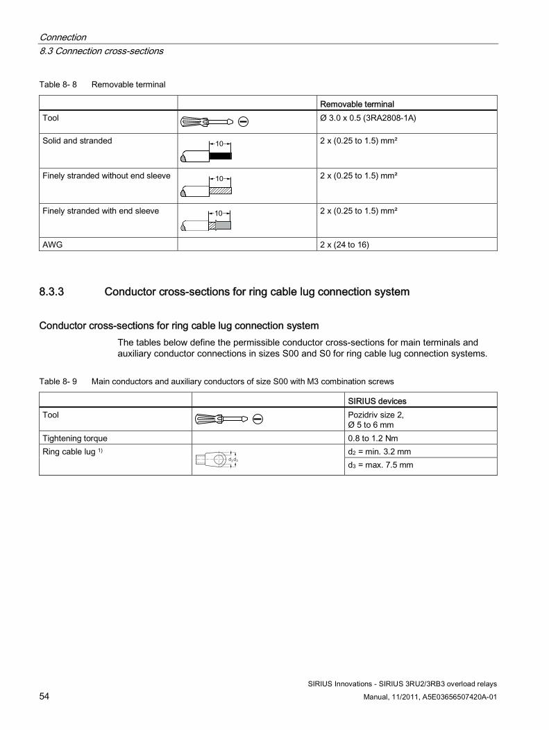
Table 8- 8 Removable terminal
Removable terminal Tool Ø 3.0 x 0.5 (3RA2808-1A)
Solid and stranded
2 x (0.25 to 1.5) mm²
Finely stranded without end sleeve
2 x (0.25 to 1.5) mm²
Finely stranded with end sleeve
2 x (0.25 to 1.5) mm²
AWG 2 x (24 to 16)
8.3.3 Conductor cross-sections for ring cable lug connection system
Conductor cross-sections for ring cable lug connection system The tables below define the permissible conductor cross-sections for main terminals and auxiliary conductor connections in sizes S00 and S0 for ring cable lug connection systems.
Table 8- 9 Main conductors and auxiliary conductors of size S00 with M3 combination screws
SIRIUS devices Tool Pozidriv size 2,
Ø 5 to 6 mm Tightening torque 0.8 to 1.2 Nm
d2 = min. 3.2 mm Ring cable lug 1) d2d3
d3 = max. 7.5 mm
Connection 8.3 Connection cross-sections
SIRIUS Innovations - SIRIUS 3RU2/3RB3 overload relays
Manual, 11/2011, A5E03656507420A-01 55
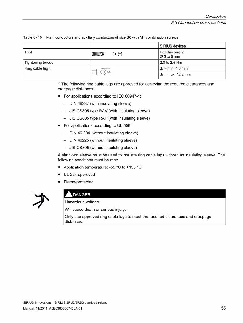
Table 8- 10 Main conductors and auxiliary conductors of size S0 with M4 combination screws
SIRIUS devices Tool Pozidriv size 2,
Ø 5 to 6 mm Tightening torque 2.0 to 2.5 Nm
d2 = min. 4.3 mm Ring cable lug 1) d2d3
d3 = max. 12.2 mm
1) The following ring cable lugs are approved for achieving the required clearances and creepage distances:
● For applications according to IEC 60947-1:
– DIN 46237 (with insulating sleeve)
– JIS CS805 type RAV (with insulating sleeve)
– JIS CS805 type RAP (with insulating sleeve)
● For applications according to UL 508:
– DIN 46 234 (without insulating sleeve)
– DIN 46225 (without insulating sleeve)
– JIS CS805 (without insulating sleeve)
A shrink-on sleeve must be used to insulate ring cable lugs without an insulating sleeve. The following conditions must be met:
● Application temperature: -55 °C to +155 °C
● UL 224 approved
● Flame-protected
DANGER
Hazardous voltage.
Will cause death or serious injury.
Only use approved ring cable lugs to meet the required clearances and creepage distances.

Connection 8.3 Connection cross-sections
SIRIUS Innovations - SIRIUS 3RU2/3RB3 overload relays
56 Manual, 11/2011, A5E03656507420A-01
SIRIUS Innovations - SIRIUS 3RU2/3RB3 overload relays
Manual, 11/2011, A5E03656507420A-01 57
Operation 99.1 Setting the current
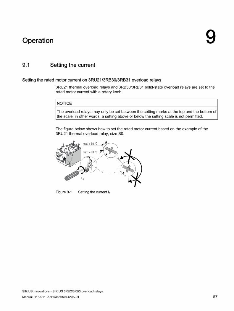
Setting the rated motor current on 3RU21/3RB30/3RB31 overload relays 3RU21 thermal overload relays and 3RB30/3RB31 solid-state overload relays are set to the rated motor current with a rotary knob.
NOTICE The overload relays may only be set between the setting marks at the top and the bottom of the scale; in other words, a setting above or below the setting scale is not permitted.
The figure below shows how to set the rated motor current based on the example of the 3RU21 thermal overload relay, size S0.
max. + 60 °C
max. + 70 °C
A
I e
Figure 9-1 Setting the current Ie
Operation 9.2 Setting the tripping class/ground-fault detection (3RB31)
SIRIUS Innovations - SIRIUS 3RU2/3RB3 overload relays
58 Manual, 11/2011, A5E03656507420A-01
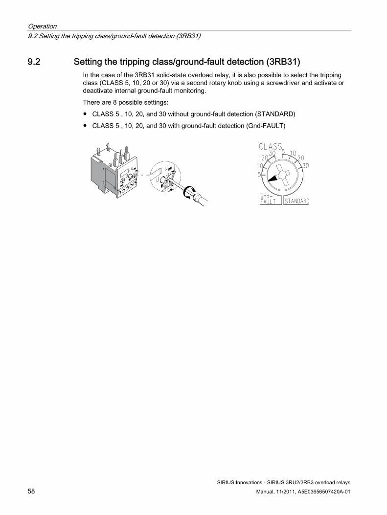
9.2 Setting the tripping class/ground-fault detection (3RB31) In the case of the 3RB31 solid-state overload relay, it is also possible to select the tripping class (CLASS 5, 10, 20 or 30) via a second rotary knob using a screwdriver and activate or deactivate internal ground-fault monitoring.
There are 8 possible settings:
● CLASS 5 , 10, 20, and 30 without ground-fault detection (STANDARD)
● CLASS 5 , 10, 20, and 30 with ground-fault detection (Gnd-FAULT)
Operation 9.3 RESET after release
SIRIUS Innovations - SIRIUS 3RU2/3RB3 overload relays
Manual, 11/2011, A5E03656507420A-01 59
9.3 RESET after release
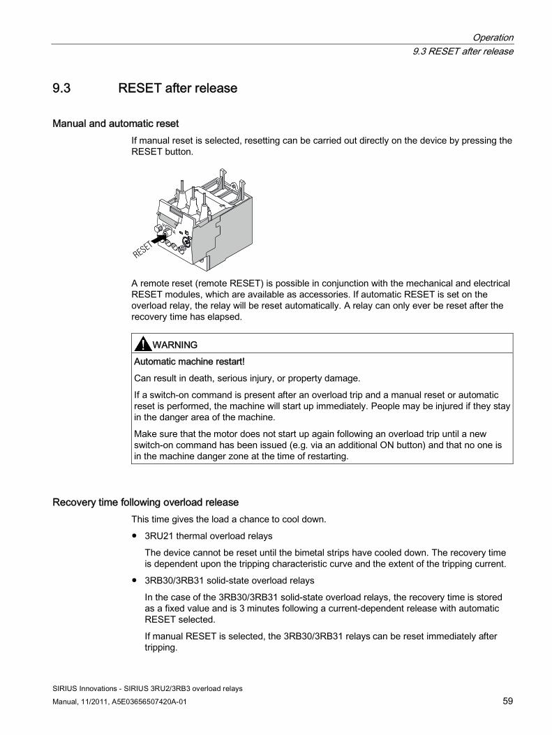
Manual and automatic reset If manual reset is selected, resetting can be carried out directly on the device by pressing the RESET button.
RESET
A remote reset (remote RESET) is possible in conjunction with the mechanical and electrical RESET modules, which are available as accessories. If automatic RESET is set on the overload relay, the relay will be reset automatically. A relay can only ever be reset after the recovery time has elapsed.
WARNING Automatic machine restart!
Can result in death, serious injury, or property damage.
If a switch-on command is present after an overload trip and a manual reset or automatic reset is performed, the machine will start up immediately. People may be injured if they stay in the danger area of the machine.
Make sure that the motor does not start up again following an overload trip until a new switch-on command has been issued (e.g. via an additional ON button) and that no one is in the machine danger zone at the time of restarting.
Recovery time following overload release This time gives the load a chance to cool down.
● 3RU21 thermal overload relays
The device cannot be reset until the bimetal strips have cooled down. The recovery time is dependent upon the tripping characteristic curve and the extent of the tripping current.
● 3RB30/3RB31 solid-state overload relays
In the case of the 3RB30/3RB31 solid-state overload relays, the recovery time is stored as a fixed value and is 3 minutes following a current-dependent release with automatic RESET selected.
If manual RESET is selected, the 3RB30/3RB31 relays can be reset immediately after tripping.
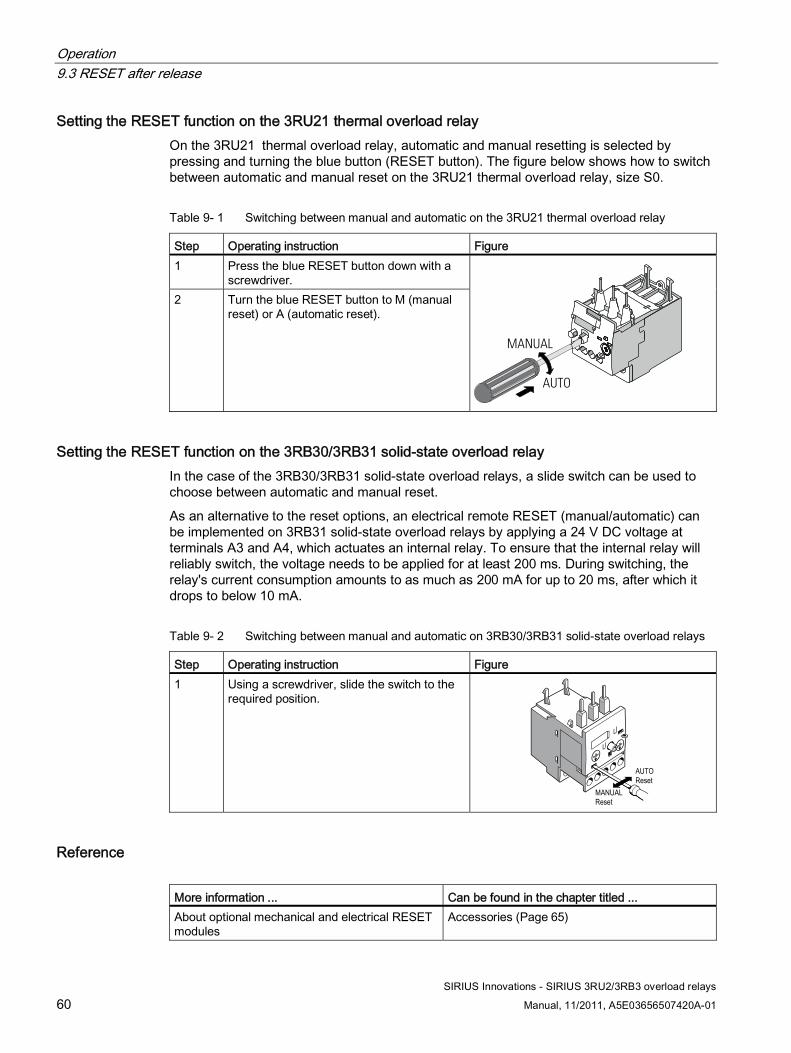
Operation 9.3 RESET after release
SIRIUS Innovations - SIRIUS 3RU2/3RB3 overload relays
60 Manual, 11/2011, A5E03656507420A-01
Setting the RESET function on the 3RU21 thermal overload relay On the 3RU21 thermal overload relay, automatic and manual resetting is selected by pressing and turning the blue button (RESET button). The figure below shows how to switch between automatic and manual reset on the 3RU21 thermal overload relay, size S0.
Table 9- 1 Switching between manual and automatic on the 3RU21 thermal overload relay
Step Operating instruction Figure 1 Press the blue RESET button down with a
screwdriver. 2 Turn the blue RESET button to M (manual
reset) or A (automatic reset).
MANUAL
AUTO
Setting the RESET function on the 3RB30/3RB31 solid-state overload relay In the case of the 3RB30/3RB31 solid-state overload relays, a slide switch can be used to choose between automatic and manual reset.
As an alternative to the reset options, an electrical remote RESET (manual/automatic) can be implemented on 3RB31 solid-state overload relays by applying a 24 V DC voltage at terminals A3 and A4, which actuates an internal relay. To ensure that the internal relay will reliably switch, the voltage needs to be applied for at least 200 ms. During switching, the relay's current consumption amounts to as much as 200 mA for up to 20 ms, after which it drops to below 10 mA.
Table 9- 2 Switching between manual and automatic on 3RB30/3RB31 solid-state overload relays
Step Operating instruction Figure 1 Using a screwdriver, slide the switch to the
required position.
MANUAL
AUTO
Reset
Reset
Reference More information ... Can be found in the chapter titled ... About optional mechanical and electrical RESET modules
Accessories (Page 65)
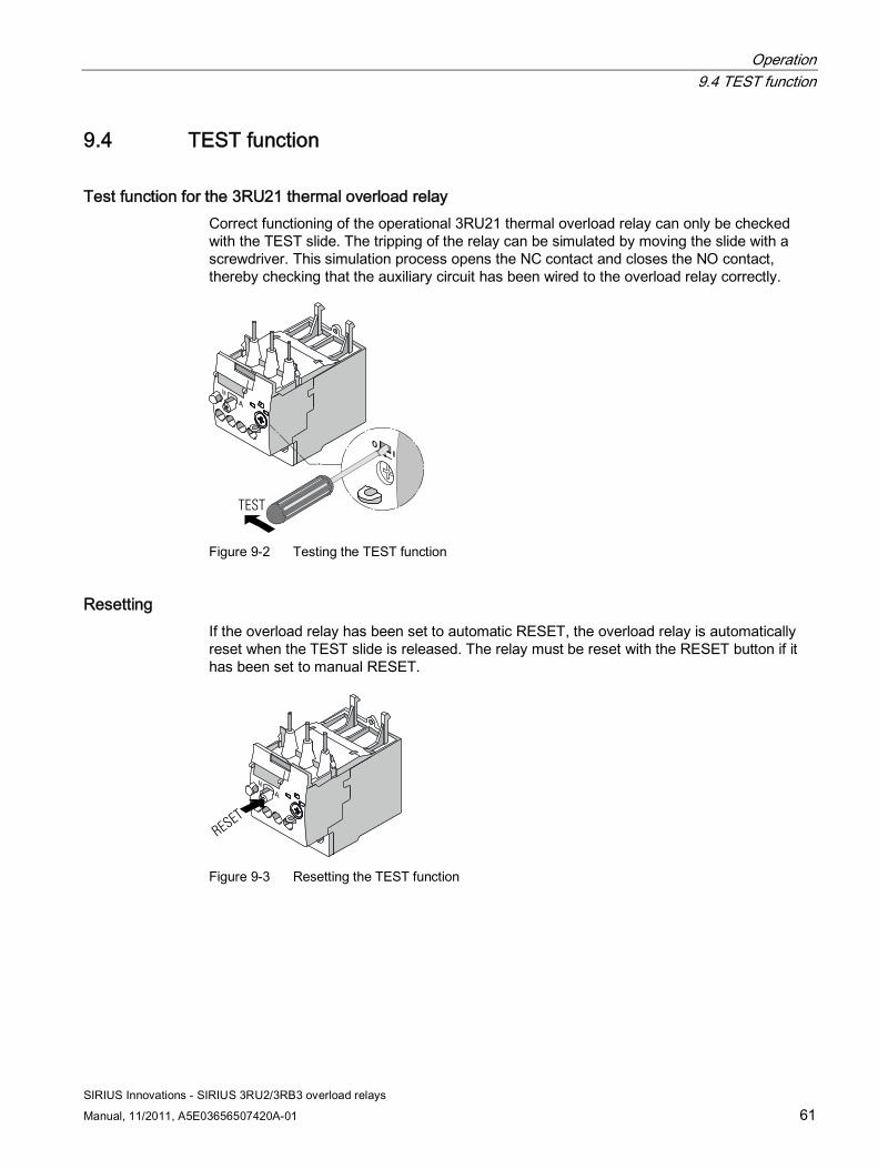
Operation 9.4 TEST function
SIRIUS Innovations - SIRIUS 3RU2/3RB3 overload relays
Manual, 11/2011, A5E03656507420A-01 61
9.4 TEST function
Test function for the 3RU21 thermal overload relay Correct functioning of the operational 3RU21 thermal overload relay can only be checked with the TEST slide. The tripping of the relay can be simulated by moving the slide with a screwdriver. This simulation process opens the NC contact and closes the NO contact, thereby checking that the auxiliary circuit has been wired to the overload relay correctly.
TEST
Figure 9-2 Testing the TEST function
Resetting If the overload relay has been set to automatic RESET, the overload relay is automatically reset when the TEST slide is released. The relay must be reset with the RESET button if it has been set to manual RESET.
RESET
Figure 9-3 Resetting the TEST function
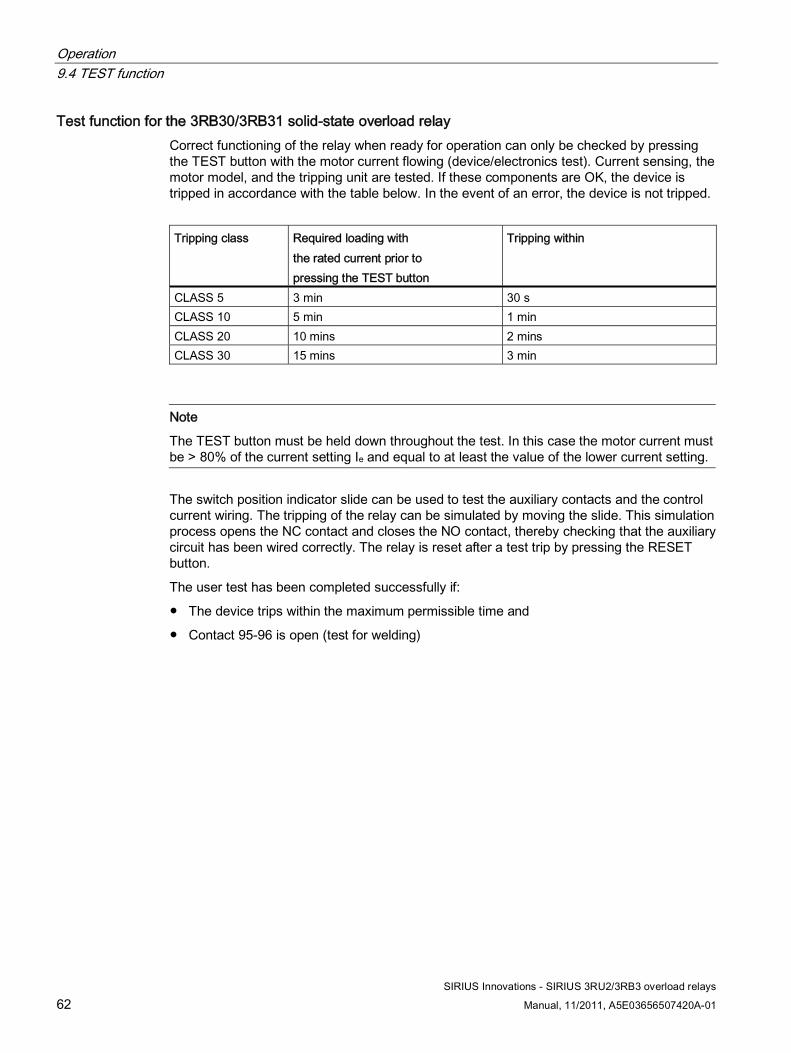
Operation 9.4 TEST function
SIRIUS Innovations - SIRIUS 3RU2/3RB3 overload relays
62 Manual, 11/2011, A5E03656507420A-01
Test function for the 3RB30/3RB31 solid-state overload relay Correct functioning of the relay when ready for operation can only be checked by pressing the TEST button with the motor current flowing (device/electronics test). Current sensing, the motor model, and the tripping unit are tested. If these components are OK, the device is tripped in accordance with the table below. In the event of an error, the device is not tripped.
Tripping class Required loading with
the rated current prior to pressing the TEST button
Tripping within
CLASS 5 3 min 30 s CLASS 10 5 min 1 min CLASS 20 10 mins 2 mins CLASS 30 15 mins 3 min
Note
The TEST button must be held down throughout the test. In this case the motor current must be > 80% of the current setting Ie and equal to at least the value of the lower current setting.
The switch position indicator slide can be used to test the auxiliary contacts and the control current wiring. The tripping of the relay can be simulated by moving the slide. This simulation process opens the NC contact and closes the NO contact, thereby checking that the auxiliary circuit has been wired correctly. The relay is reset after a test trip by pressing the RESET button.
The user test has been completed successfully if:
● The device trips within the maximum permissible time and
● Contact 95-96 is open (test for welding)
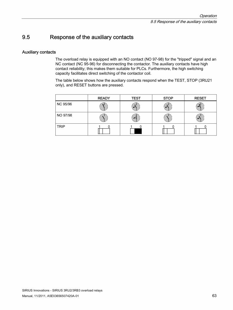
Operation 9.5 Response of the auxiliary contacts
SIRIUS Innovations - SIRIUS 3RU2/3RB3 overload relays
Manual, 11/2011, A5E03656507420A-01 63
9.5 Response of the auxiliary contacts
Auxiliary contacts The overload relay is equipped with an NO contact (NO 97-98) for the "tripped" signal and an NC contact (NC 95-96) for disconnecting the contactor. The auxiliary contacts have high contact reliability; this makes them suitable for PLCs. Furthermore, the high switching capacity facilitates direct switching of the contactor coil.
The table below shows how the auxiliary contacts respond when the TEST, STOP (3RU21 only), and RESET buttons are pressed.
READY TEST STOP RESET
NC 95/96
NO 97/98
TRIP 1 0
1 0
1 0
1 0

Operation 9.5 Response of the auxiliary contacts
SIRIUS Innovations - SIRIUS 3RU2/3RB3 overload relays
64 Manual, 11/2011, A5E03656507420A-01
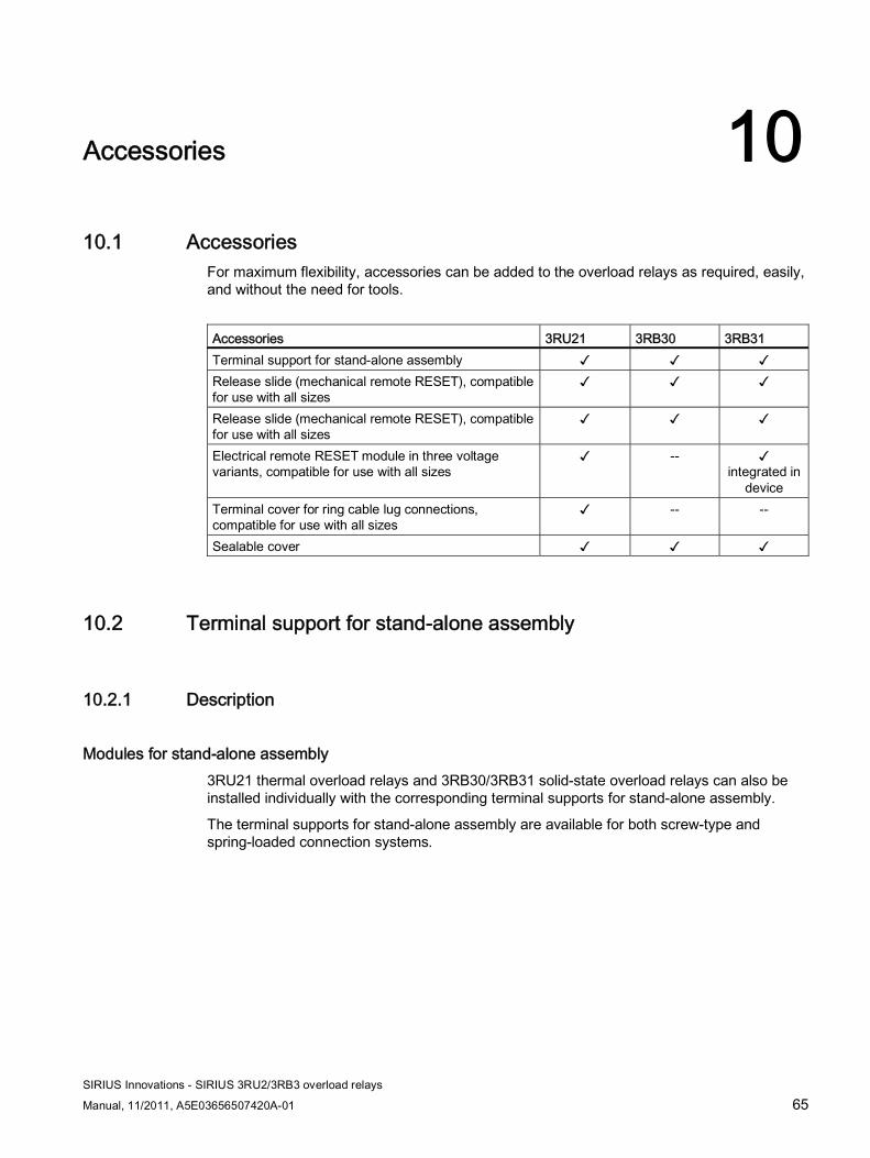
SIRIUS Innovations - SIRIUS 3RU2/3RB3 overload relays
Manual, 11/2011, A5E03656507420A-01 65
Accessories 1010.1 Accessories
For maximum flexibility, accessories can be added to the overload relays as required, easily, and without the need for tools.
Accessories 3RU21 3RB30 3RB31 Terminal support for stand-alone assembly ✓ ✓ ✓ Release slide (mechanical remote RESET), compatible for use with all sizes
✓ ✓ ✓
Release slide (mechanical remote RESET), compatible for use with all sizes
✓ ✓ ✓
Electrical remote RESET module in three voltage variants, compatible for use with all sizes
✓ -- ✓ integrated in
device Terminal cover for ring cable lug connections, compatible for use with all sizes
✓ -- --
Sealable cover ✓ ✓ ✓
10.2 Terminal support for stand-alone assembly
10.2.1 Description
Modules for stand-alone assembly 3RU21 thermal overload relays and 3RB30/3RB31 solid-state overload relays can also be installed individually with the corresponding terminal supports for stand-alone assembly.
The terminal supports for stand-alone assembly are available for both screw-type and spring-loaded connection systems.
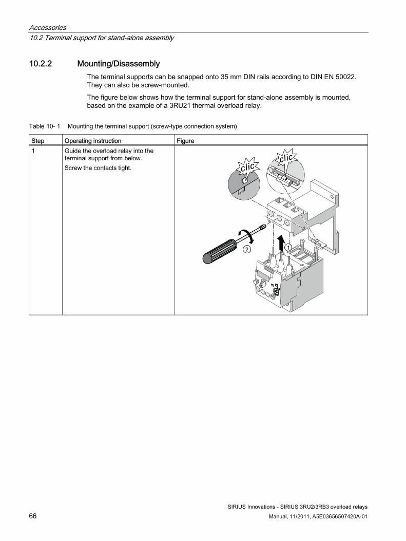
Accessories 10.2 Terminal support for stand-alone assembly
SIRIUS Innovations - SIRIUS 3RU2/3RB3 overload relays
66 Manual, 11/2011, A5E03656507420A-01
10.2.2 Mounting/Disassembly The terminal supports can be snapped onto 35 mm DIN rails according to DIN EN 50022. They can also be screw-mounted.
The figure below shows how the terminal support for stand-alone assembly is mounted, based on the example of a 3RU21 thermal overload relay.
Table 10- 1 Mounting the terminal support (screw-type connection system)
Step Operating instruction Figure 1 Guide the overload relay into the
terminal support from below. Screw the contacts tight.
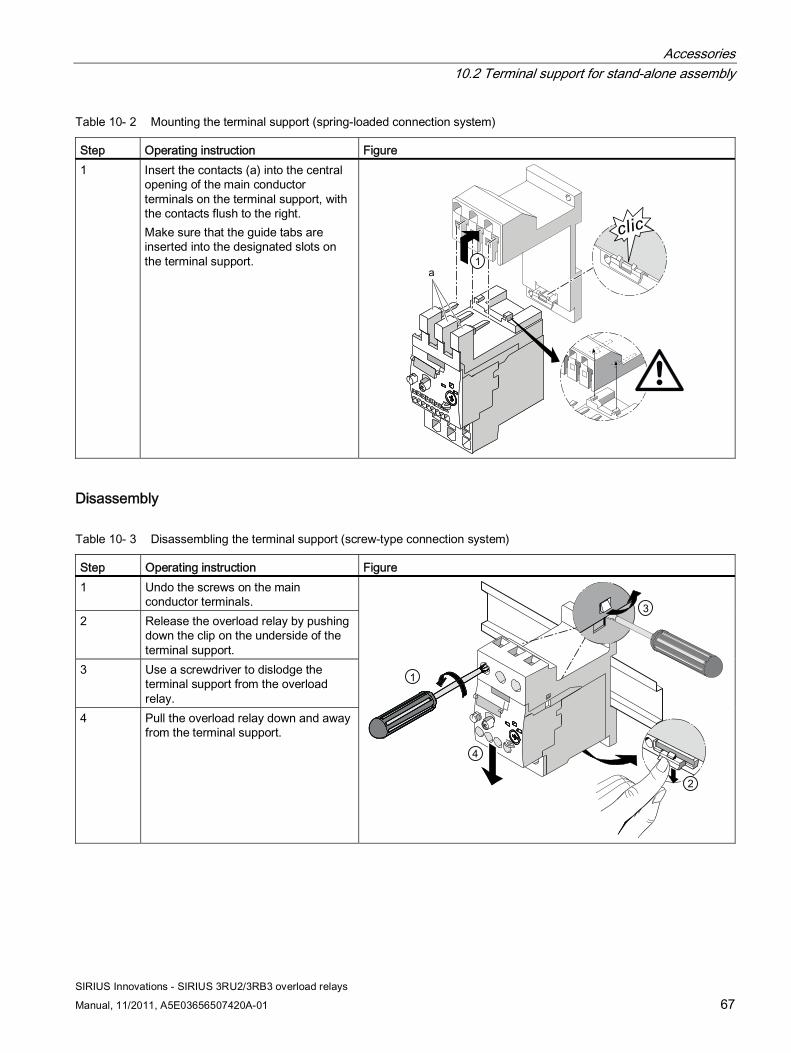
Accessories 10.2 Terminal support for stand-alone assembly
SIRIUS Innovations - SIRIUS 3RU2/3RB3 overload relays
Manual, 11/2011, A5E03656507420A-01 67
Table 10- 2 Mounting the terminal support (spring-loaded connection system)
Step Operating instruction Figure 1 Insert the contacts (a) into the central
opening of the main conductor terminals on the terminal support, with the contacts flush to the right. Make sure that the guide tabs are inserted into the designated slots on the terminal support.
Disassembly
Table 10- 3 Disassembling the terminal support (screw-type connection system)
Step Operating instruction Figure 1 Undo the screws on the main
conductor terminals. 2 Release the overload relay by pushing
down the clip on the underside of the terminal support.
3 Use a screwdriver to dislodge the terminal support from the overload relay.
4 Pull the overload relay down and away from the terminal support.
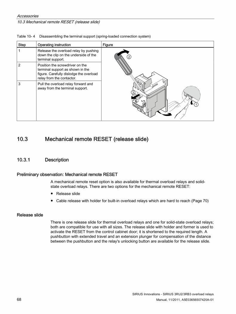
Accessories 10.3 Mechanical remote RESET (release slide)
SIRIUS Innovations - SIRIUS 3RU2/3RB3 overload relays
68 Manual, 11/2011, A5E03656507420A-01
Table 10- 4 Disassembling the terminal support (spring-loaded connection system)
Step Operating instruction Figure 1 Release the overload relay by pushing
down the clip on the underside of the terminal support.
2 Position the screwdriver on the terminal support as shown in the figure. Carefully dislodge the overload relay from the contactor.
3 Pull the overload relay forward and away from the terminal support.
10.3 Mechanical remote RESET (release slide)
10.3.1 Description
Preliminary observation: Mechanical remote RESET A mechanical remote reset option is also available for thermal overload relays and solid-state overload relays. There are two options for the mechanical remote RESET:
● Release slide
● Cable release with holder for built-in overload relays which are hard to reach (Page 70)
Release slide There is one release slide for thermal overload relays and one for solid-state overload relays; both are compatible for use with all sizes. The release slide with holder and former is used to activate the RESET from the control cabinet door; it is shortened to the required length. A pushbutton with extended travel and an extension plunger for compensation of the distance between the pushbutton and the relay's unlocking button are available for the release slide.
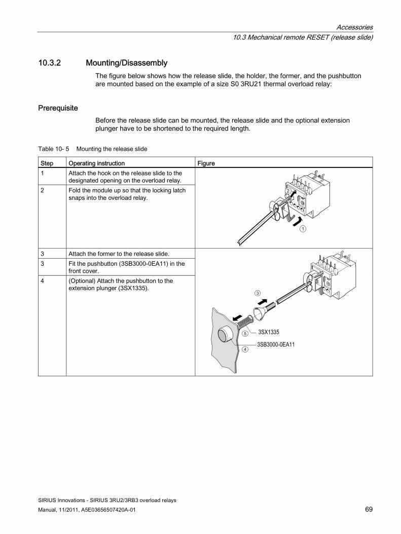
Accessories 10.3 Mechanical remote RESET (release slide)
SIRIUS Innovations - SIRIUS 3RU2/3RB3 overload relays
Manual, 11/2011, A5E03656507420A-01 69
10.3.2 Mounting/Disassembly The figure below shows how the release slide, the holder, the former, and the pushbutton are mounted based on the example of a size S0 3RU21 thermal overload relay:
Prerequisite Before the release slide can be mounted, the release slide and the optional extension plunger have to be shortened to the required length.
Table 10- 5 Mounting the release slide
Step Operating instruction Figure 1 Attach the hook on the release slide to the
designated opening on the overload relay. 2 Fold the module up so that the locking latch
snaps into the overload relay.
1
2
3 Attach the former to the release slide. 3 Fit the pushbutton (3SB3000-0EA11) in the
front cover. 4 (Optional) Attach the pushbutton to the
extension plunger (3SX1335).
3SX1335
3SB3000-0EA11
3
4
5
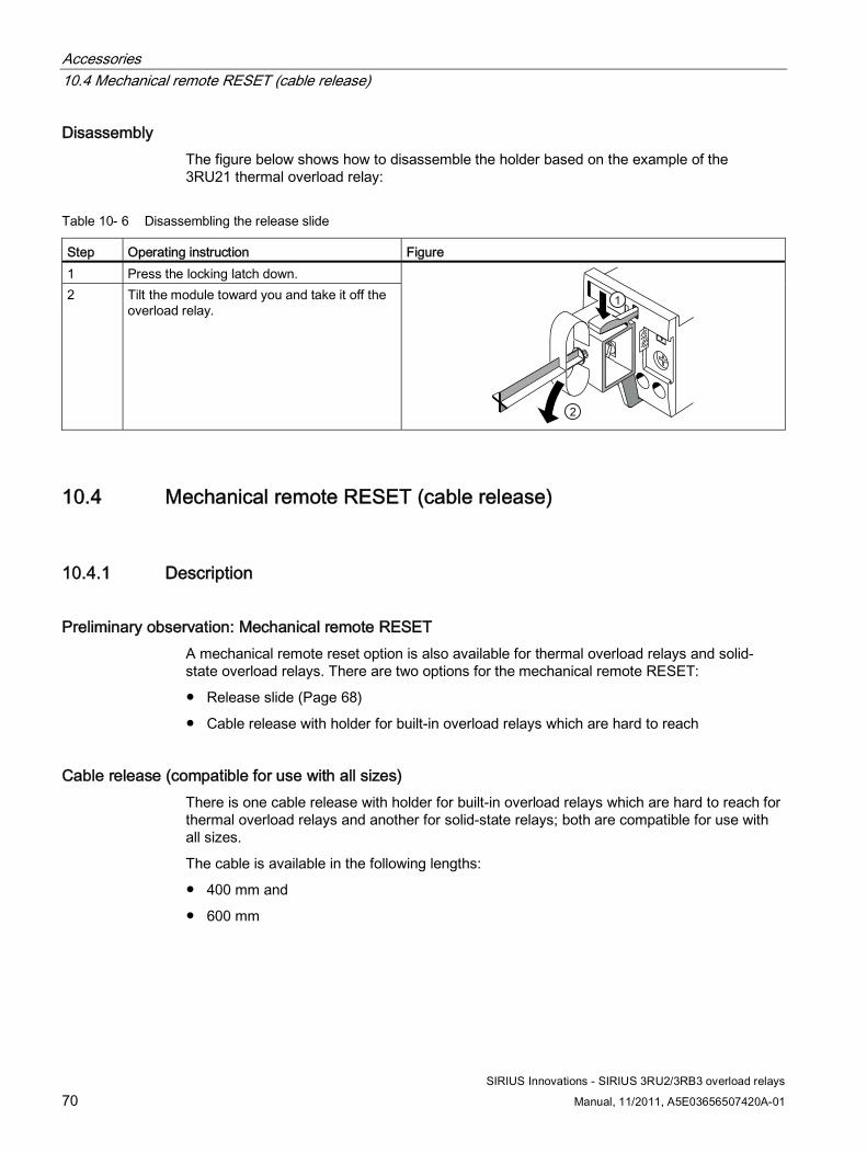
Accessories 10.4 Mechanical remote RESET (cable release)
SIRIUS Innovations - SIRIUS 3RU2/3RB3 overload relays
70 Manual, 11/2011, A5E03656507420A-01
Disassembly The figure below shows how to disassemble the holder based on the example of the 3RU21 thermal overload relay:
Table 10- 6 Disassembling the release slide
Step Operating instruction Figure 1 Press the locking latch down. 2 Tilt the module toward you and take it off the
overload relay.
10.4 Mechanical remote RESET (cable release)
10.4.1 Description
Preliminary observation: Mechanical remote RESET A mechanical remote reset option is also available for thermal overload relays and solid-state overload relays. There are two options for the mechanical remote RESET:
● Release slide (Page 68)
● Cable release with holder for built-in overload relays which are hard to reach
Cable release (compatible for use with all sizes) There is one cable release with holder for built-in overload relays which are hard to reach for thermal overload relays and another for solid-state relays; both are compatible for use with all sizes.
The cable is available in the following lengths:
● 400 mm and
● 600 mm
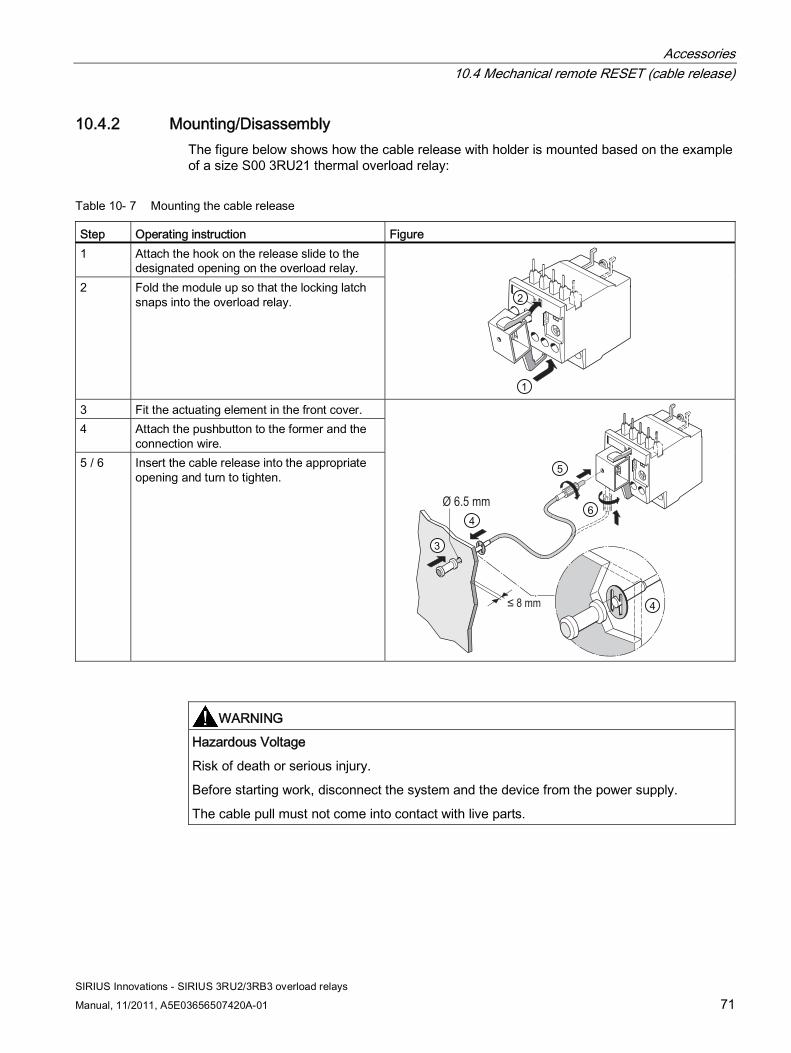
Accessories 10.4 Mechanical remote RESET (cable release)
SIRIUS Innovations - SIRIUS 3RU2/3RB3 overload relays
Manual, 11/2011, A5E03656507420A-01 71
10.4.2 Mounting/Disassembly The figure below shows how the cable release with holder is mounted based on the example of a size S00 3RU21 thermal overload relay:
Table 10- 7 Mounting the cable release
Step Operating instruction Figure 1 Attach the hook on the release slide to the
designated opening on the overload relay. 2 Fold the module up so that the locking latch
snaps into the overload relay.
3 Fit the actuating element in the front cover. 4 Attach the pushbutton to the former and the
connection wire. 5 / 6 Insert the cable release into the appropriate
opening and turn to tighten.
Ø 6.5 mm
≤ 8 mm
WARNING Hazardous Voltage
Risk of death or serious injury.
Before starting work, disconnect the system and the device from the power supply.
The cable pull must not come into contact with live parts.
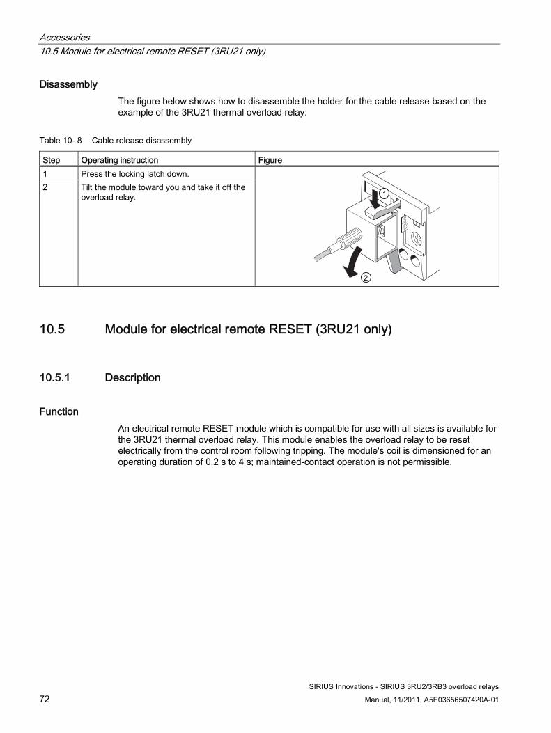
Accessories 10.5 Module for electrical remote RESET (3RU21 only)
SIRIUS Innovations - SIRIUS 3RU2/3RB3 overload relays
72 Manual, 11/2011, A5E03656507420A-01
Disassembly The figure below shows how to disassemble the holder for the cable release based on the example of the 3RU21 thermal overload relay:
Table 10- 8 Cable release disassembly
Step Operating instruction Figure 1 Press the locking latch down. 2 Tilt the module toward you and take it off the
overload relay.
10.5 Module for electrical remote RESET (3RU21 only)
10.5.1 Description
Function An electrical remote RESET module which is compatible for use with all sizes is available for the 3RU21 thermal overload relay. This module enables the overload relay to be reset electrically from the control room following tripping. The module's coil is dimensioned for an operating duration of 0.2 s to 4 s; maintained-contact operation is not permissible.
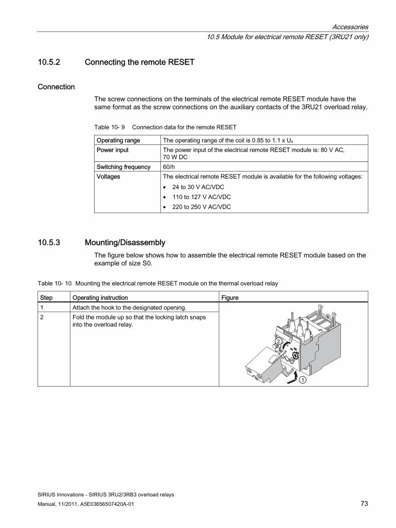
Accessories 10.5 Module for electrical remote RESET (3RU21 only)
SIRIUS Innovations - SIRIUS 3RU2/3RB3 overload relays
Manual, 11/2011, A5E03656507420A-01 73
10.5.2 Connecting the remote RESET
Connection The screw connections on the terminals of the electrical remote RESET module have the same format as the screw connections on the auxiliary contacts of the 3RU21 overload relay.
Table 10- 9 Connection data for the remote RESET
Operating range The operating range of the coil is 0.85 to 1.1 x Us Power input The power input of the electrical remote RESET module is: 80 V AC,
70 W DC Switching frequency 60/h Voltages The electrical remote RESET module is available for the following voltages:
• 24 to 30 V AC/VDC • 110 to 127 V AC/VDC • 220 to 250 V AC/VDC
10.5.3 Mounting/Disassembly The figure below shows how to assemble the electrical remote RESET module based on the example of size S0.
Table 10- 10 Mounting the electrical remote RESET module on the thermal overload relay
Step Operating instruction Figure 1 Attach the hook to the designated opening. 2 Fold the module up so that the locking latch snaps
into the overload relay.
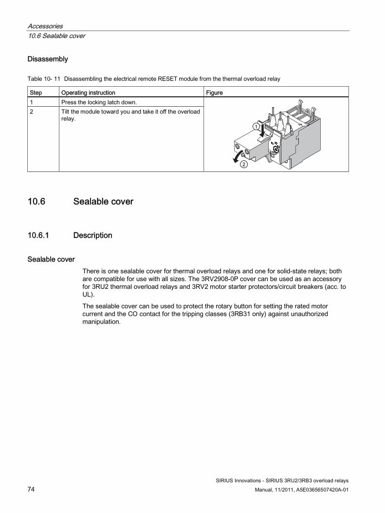
Accessories 10.6 Sealable cover
SIRIUS Innovations - SIRIUS 3RU2/3RB3 overload relays
74 Manual, 11/2011, A5E03656507420A-01
Disassembly
Table 10- 11 Disassembling the electrical remote RESET module from the thermal overload relay
Step Operating instruction Figure 1 Press the locking latch down. 2 Tilt the module toward you and take it off the overload
relay.
10.6 Sealable cover
10.6.1 Description
Sealable cover There is one sealable cover for thermal overload relays and one for solid-state relays; both are compatible for use with all sizes. The 3RV2908-0P cover can be used as an accessory for 3RU2 thermal overload relays and 3RV2 motor starter protectors/circuit breakers (acc. to UL).
The sealable cover can be used to protect the rotary button for setting the rated motor current and the CO contact for the tripping classes (3RB31 only) against unauthorized manipulation.
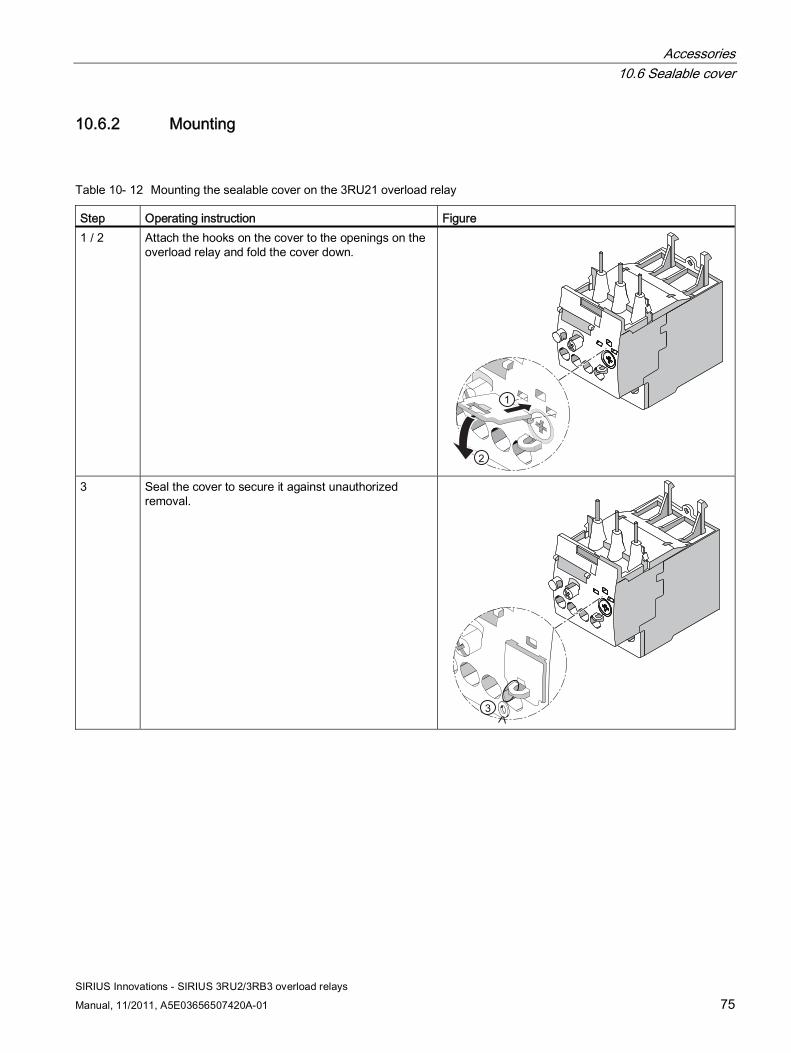
Accessories 10.6 Sealable cover
SIRIUS Innovations - SIRIUS 3RU2/3RB3 overload relays
Manual, 11/2011, A5E03656507420A-01 75
10.6.2 Mounting
Table 10- 12 Mounting the sealable cover on the 3RU21 overload relay
Step Operating instruction Figure 1 / 2 Attach the hooks on the cover to the openings on the
overload relay and fold the cover down.
3 Seal the cover to secure it against unauthorized
removal.
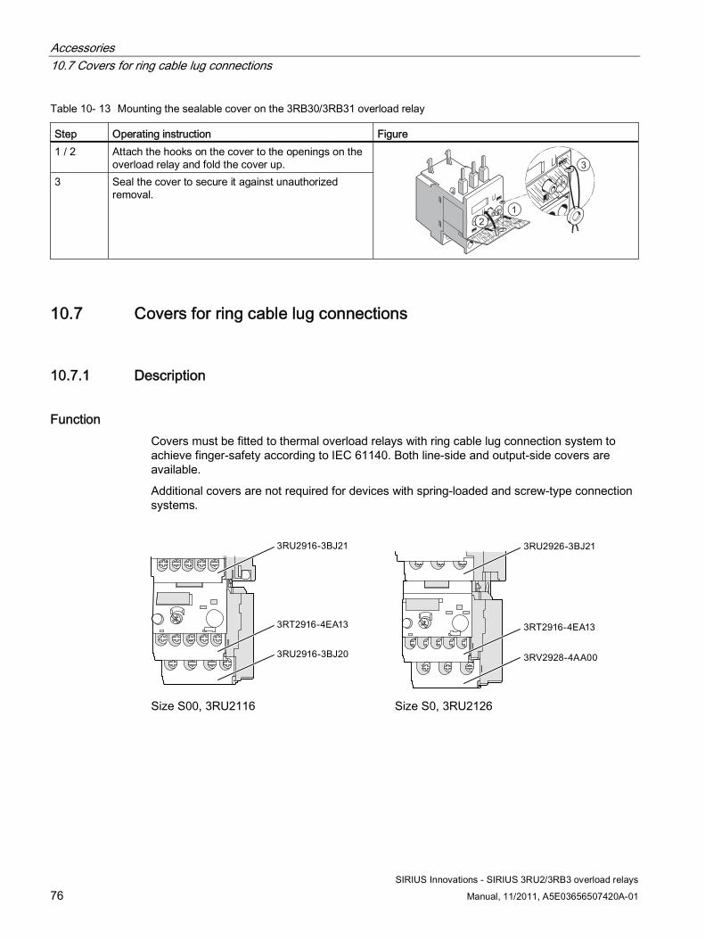
Accessories 10.7 Covers for ring cable lug connections
SIRIUS Innovations - SIRIUS 3RU2/3RB3 overload relays
76 Manual, 11/2011, A5E03656507420A-01
Table 10- 13 Mounting the sealable cover on the 3RB30/3RB31 overload relay
Step Operating instruction Figure 1 / 2 Attach the hooks on the cover to the openings on the
overload relay and fold the cover up. 3 Seal the cover to secure it against unauthorized
removal.
10.7 Covers for ring cable lug connections
10.7.1 Description
Function Covers must be fitted to thermal overload relays with ring cable lug connection system to achieve finger-safety according to IEC 61140. Both line-side and output-side covers are available.
Additional covers are not required for devices with spring-loaded and screw-type connection systems.
Size S00, 3RU2116 Size S0, 3RU2126
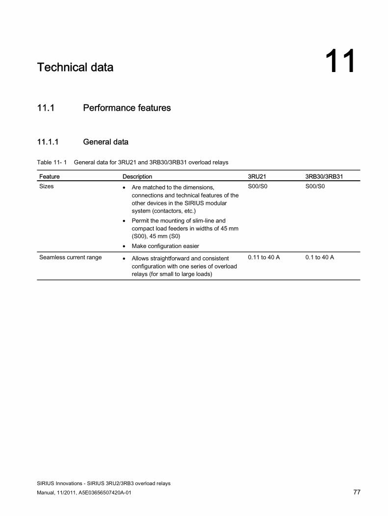
SIRIUS Innovations - SIRIUS 3RU2/3RB3 overload relays
Manual, 11/2011, A5E03656507420A-01 77
Technical data 1111.1 Performance features
11.1.1 General data
Table 11- 1 General data for 3RU21 and 3RB30/3RB31 overload relays
Feature Description 3RU21 3RB30/3RB31 Sizes • Are matched to the dimensions,
connections and technical features of the other devices in the SIRIUS modular system (contactors, etc.)
• Permit the mounting of slim-line and compact load feeders in widths of 45 mm (S00), 45 mm (S0)
• Make configuration easier
S00/S0 S00/S0
Seamless current range • Allows straightforward and consistent configuration with one series of overload relays (for small to large loads)
0.11 to 40 A 0.1 to 40 A
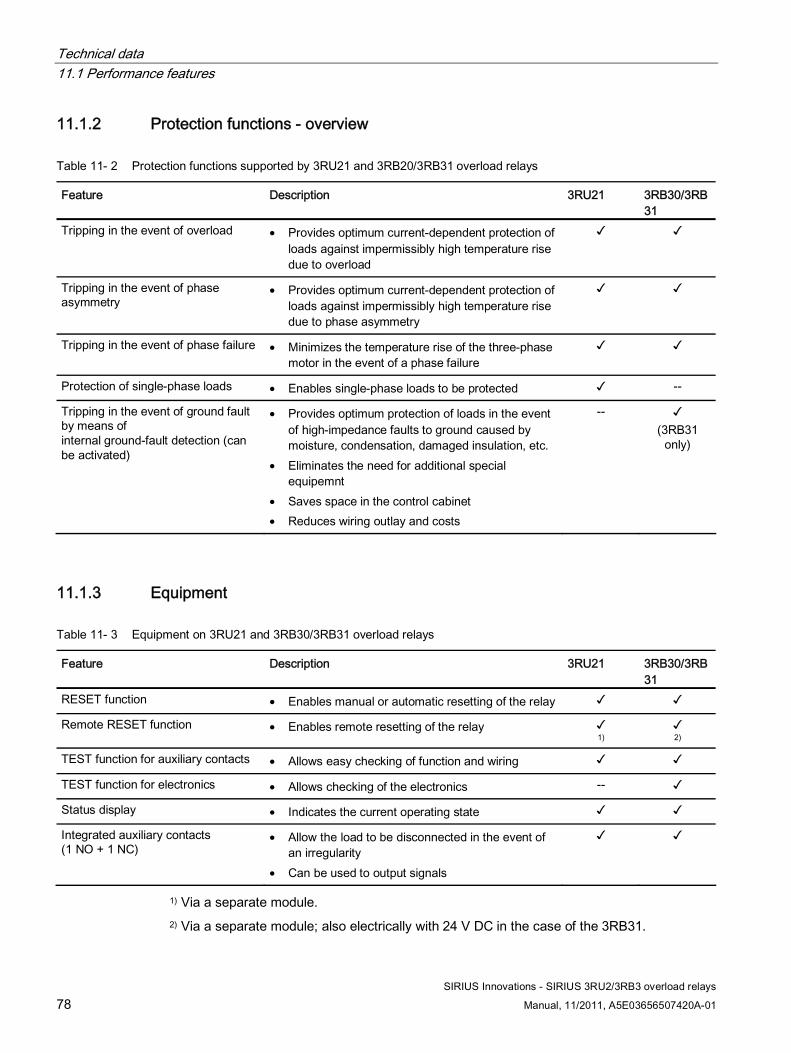
Technical data 11.1 Performance features
SIRIUS Innovations - SIRIUS 3RU2/3RB3 overload relays
78 Manual, 11/2011, A5E03656507420A-01
11.1.2 Protection functions - overview
Table 11- 2 Protection functions supported by 3RU21 and 3RB20/3RB31 overload relays
Feature Description 3RU21 3RB30/3RB31
Tripping in the event of overload • Provides optimum current-dependent protection of loads against impermissibly high temperature rise due to overload
✓ ✓
Tripping in the event of phase asymmetry
• Provides optimum current-dependent protection of loads against impermissibly high temperature rise due to phase asymmetry
✓ ✓
Tripping in the event of phase failure • Minimizes the temperature rise of the three-phase motor in the event of a phase failure
✓ ✓
Protection of single-phase loads • Enables single-phase loads to be protected ✓ --
Tripping in the event of ground fault by means of internal ground-fault detection (can be activated)
• Provides optimum protection of loads in the event of high-impedance faults to ground caused by moisture, condensation, damaged insulation, etc.
• Eliminates the need for additional special equipemnt
• Saves space in the control cabinet • Reduces wiring outlay and costs
-- ✓ (3RB31
only)
11.1.3 Equipment
Table 11- 3 Equipment on 3RU21 and 3RB30/3RB31 overload relays
Feature Description 3RU21 3RB30/3RB31
RESET function • Enables manual or automatic resetting of the relay ✓ ✓
Remote RESET function • Enables remote resetting of the relay ✓ 1)
✓ 2)
TEST function for auxiliary contacts • Allows easy checking of function and wiring ✓ ✓
TEST function for electronics • Allows checking of the electronics -- ✓
Status display • Indicates the current operating state ✓ ✓
Integrated auxiliary contacts (1 NO + 1 NC)
• Allow the load to be disconnected in the event of an irregularity
• Can be used to output signals
✓ ✓
1) Via a separate module. 2) Via a separate module; also electrically with 24 V DC in the case of the 3RB31.
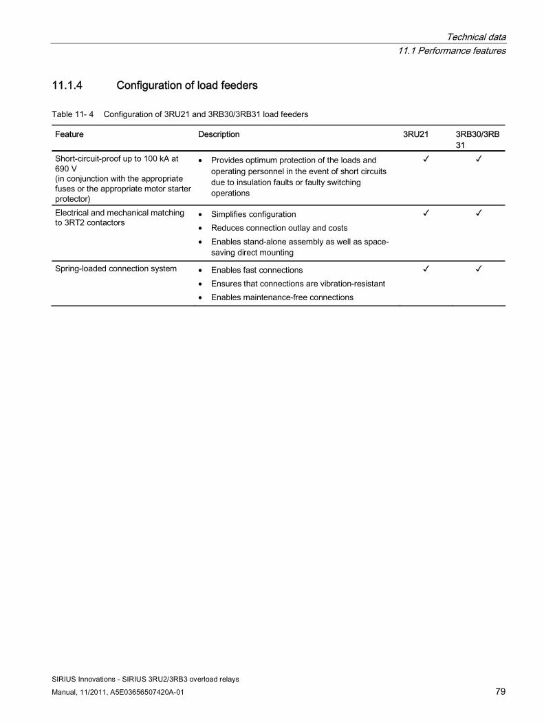
Technical data 11.1 Performance features
SIRIUS Innovations - SIRIUS 3RU2/3RB3 overload relays
Manual, 11/2011, A5E03656507420A-01 79
11.1.4 Configuration of load feeders
Table 11- 4 Configuration of 3RU21 and 3RB30/3RB31 load feeders
Feature Description 3RU21 3RB30/3RB31
Short-circuit-proof up to 100 kA at 690 V (in conjunction with the appropriate fuses or the appropriate motor starter protector)
• Provides optimum protection of the loads and operating personnel in the event of short circuits due to insulation faults or faulty switching operations
✓ ✓
Electrical and mechanical matching to 3RT2 contactors
• Simplifies configuration • Reduces connection outlay and costs • Enables stand-alone assembly as well as space-
saving direct mounting
✓ ✓
Spring-loaded connection system • Enables fast connections • Ensures that connections are vibration-resistant • Enables maintenance-free connections
✓ ✓
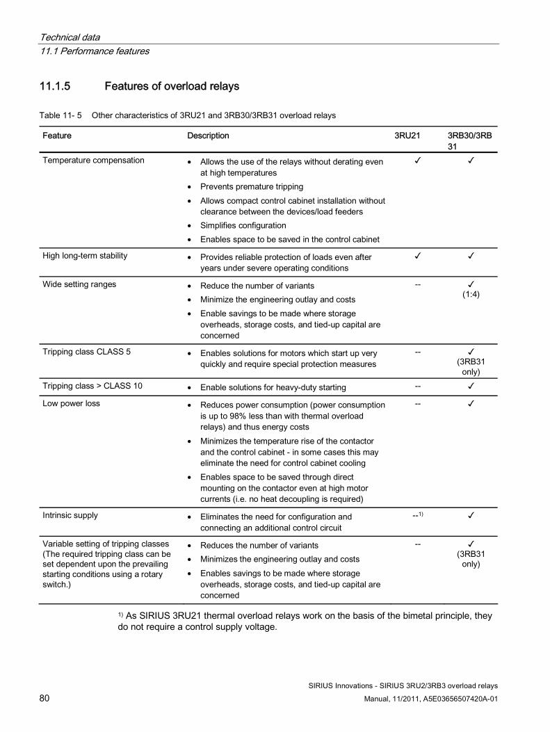
Technical data 11.1 Performance features
SIRIUS Innovations - SIRIUS 3RU2/3RB3 overload relays
80 Manual, 11/2011, A5E03656507420A-01
11.1.5 Features of overload relays
Table 11- 5 Other characteristics of 3RU21 and 3RB30/3RB31 overload relays
Feature Description 3RU21 3RB30/3RB31
Temperature compensation • Allows the use of the relays without derating even at high temperatures
• Prevents premature tripping • Allows compact control cabinet installation without
clearance between the devices/load feeders • Simplifies configuration • Enables space to be saved in the control cabinet
✓ ✓
High long-term stability • Provides reliable protection of loads even after years under severe operating conditions
✓ ✓
Wide setting ranges • Reduce the number of variants • Minimize the engineering outlay and costs • Enable savings to be made where storage
overheads, storage costs, and tied-up capital are concerned
-- ✓ (1:4)
Tripping class CLASS 5 • Enables solutions for motors which start up very quickly and require special protection measures
-- ✓ (3RB31
only) Tripping class > CLASS 10 • Enable solutions for heavy-duty starting -- ✓
Low power loss • Reduces power consumption (power consumption is up to 98% less than with thermal overload relays) and thus energy costs
• Minimizes the temperature rise of the contactor and the control cabinet - in some cases this may eliminate the need for control cabinet cooling
• Enables space to be saved through direct mounting on the contactor even at high motor currents (i.e. no heat decoupling is required)
-- ✓
Intrinsic supply • Eliminates the need for configuration and connecting an additional control circuit
--1) ✓
Variable setting of tripping classes (The required tripping class can be set dependent upon the prevailing starting conditions using a rotary switch.)
• Reduces the number of variants • Minimizes the engineering outlay and costs • Enables savings to be made where storage
overheads, storage costs, and tied-up capital are concerned
-- ✓ (3RB31
only)
1) As SIRIUS 3RU21 thermal overload relays work on the basis of the bimetal principle, they do not require a control supply voltage.
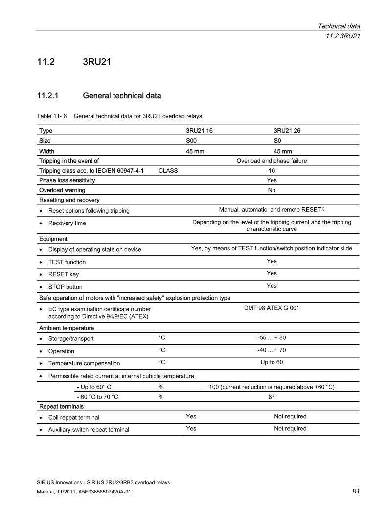
Technical data 11.2 3RU21
SIRIUS Innovations - SIRIUS 3RU2/3RB3 overload relays
Manual, 11/2011, A5E03656507420A-01 81
11.2 3RU21
11.2.1 General technical data
Table 11- 6 General technical data for 3RU21 overload relays
Type 3RU21 16 3RU21 26 Size S00 S0
Width 45 mm 45 mm Tripping in the event of Overload and phase failure Tripping class acc. to IEC/EN 60947-4-1 CLASS 10 Phase loss sensitivity Yes Overload warning No Resetting and recovery
• Reset options following tripping Manual, automatic, and remote RESET1)
• Recovery time Depending on the level of the tripping current and the tripping characteristic curve
Equipment
• Display of operating state on device Yes, by means of TEST function/switch position indicator slide
• TEST function Yes
• RESET key Yes
• STOP button Yes
Safe operation of motors with "increased safety" explosion protection type
• EC type examination certificate number according to Directive 94/9/EC (ATEX)
DMT 98 ATEX G 001
Ambient temperature
• Storage/transport °C -55 ... + 80
• Operation °C -40 ... + 70
• Temperature compensation °C Up to 60
• Permissible rated current at internal cubicle temperature
- Up to 60° C % 100 (current reduction is required above +60 °C) - 60 °C to 70 °C % 87
Repeat terminals
• Coil repeat terminal Yes Not required
• Auxiliary switch repeat terminal Yes Not required

Technical data 11.2 3RU21
SIRIUS Innovations - SIRIUS 3RU2/3RB3 overload relays
82 Manual, 11/2011, A5E03656507420A-01
Type 3RU21 16 3RU21 26
Size S00 S0 Width 45 mm 45 mm Degree of protection acc. to IEC 60529 IP20 Touch protection acc. to IEC 61140 Screw connection and spring-loaded terminals: finger-safe
Ring cable lug connection: finger-safe only with optional terminal covers
Shock resistance with sine acc. to IEC 60068-2-27
g/ms 15 / 11 2)
Resistance to extreme climates - Humidity % 90 Dimensions See Dimension drawings for 3RU21 thermal overload relays
(Page 107) Installation altitude above sea level m Up to 2,000; above this, please contact us Mounting position See Minimum clearances and mounting position (Page 41) Type of fixing Contactor mounting/stand-alone assembly with terminal support3)
1) Remote RESET in conjunction with the appropriate accessory 2) Auxiliary contacts 95/96 and 97/98: 8 g/11 ms. 3) For screw and snap-on mounting onto DIN rail TH 35.

Technical data 11.2 3RU21
SIRIUS Innovations - SIRIUS 3RU2/3RB3 overload relays
Manual, 11/2011, A5E03656507420A-01 83
11.2.2 Main circuit
Table 11- 7 Technical data for the main circuit, 3RU21 overload relays
Type 3RU21 16 3RU21 26 Size S00 S0
Width 45 mm 45 mm Rated insulation voltage Ui (pollution degree 3)
V 690
Rated impulse withstand voltage Uimp kV 6 Rated operational voltage Ue V 690 Type of current
• DC current Yes
• AC current Yes, frequency range up to 400 Hz
Current setting A 0.11 to 0.16 to 11 to 16
1.8 to 2.5 to 34 to 40
Power loss per device (max.) W 3.9 to 6.6 3.9 to 6 Short-circuit protection
• With fuse without contactor See "Selection and ordering data" in Catalog IC 10 - SIRIUS
• With fuse and contactor See the configuration guide titled "Configuring SIRIUS Innovations - Selection data for load feeders in fuseless and fused designs (http://support.automation.siemens.com/WW/view/en/50250592)".
Protective separation between main and auxiliary courrent paths acc. to IEC/EN 60947-1
V 440 440 / 690 2)
2) 690 V operating voltage for protective separation applies to devices with screw or ring cable lug connection up to the 25 A setting range. 440 V applies in excess of this and in the case of devices with spring-loaded connection.
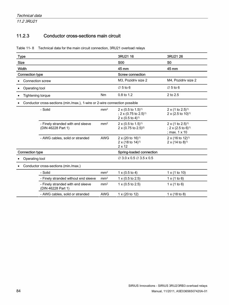
Technical data 11.2 3RU21
SIRIUS Innovations - SIRIUS 3RU2/3RB3 overload relays
84 Manual, 11/2011, A5E03656507420A-01
11.2.3 Conductor cross-sections main circuit
Table 11- 8 Technical data for the main circuit connection, 3RU21 overload relays
Type 3RU21 16 3RU21 26 Size S00 S0
Width 45 mm 45 mm Connection type Screw connection
• Connection screw M3, Pozidriv size 2 M4, Pozidriv size 2
• Operating tool ∅ 5 to 6 ∅ 5 to 6
• Tightening torque Nm 0.8 to 1.2 2 to 2.5
• Conductor cross-sections (min./max.), 1-wire or 2-wire connection possible
- Solid mm2 2 x (0.5 to 1.5)1) ; 2 x (0.75 to 2.5)1) 2 x (0.5 to 4)1)
2 x (1 to 2.5)1) 2 x (2.5 to 10)1)
- Finely stranded with end sleeve (DIN 46228 Part 1)
mm2 2 x (0.5 to 1.5)1) 2 x (0.75 to 2.5)2)
2 x (1 to 2.5)1) ; 2 x (2.5 to 6)1)
; max. 1 x 10
- AWG cables, solid or stranded AWG 2 x (20 to 16)1) 2 x (18 to 14)1)
2 x 12
2 x (16 to 12)1)
2 x (14 to 8)1)
Connection type Spring-loaded connection
• Operating tool ∅ 3.0 x 0.5 ∅ 3.5 x 0.5
• Conductor cross-sections (min./max.)
- Solid mm2 1 x (0.5 to 4) 1 x (1 to 10) - Finely stranded without end sleeve mm2 1 x (0.5 to 2.5) 1 x (1 to 6) - Finely stranded with end sleeve (DIN 46228 Part 1)
mm2 1 x (0.5 to 2.5) 1 x (1 to 6)
- AWG cables, solid or stranded AWG 1 x (20 to 12) 1 x (18 to 8)
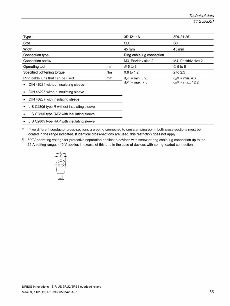
Technical data 11.2 3RU21
SIRIUS Innovations - SIRIUS 3RU2/3RB3 overload relays
Manual, 11/2011, A5E03656507420A-01 85
Type 3RU21 16 3RU21 26
Size S00 S0 Width 45 mm 45 mm Connection type Ring cable lug connection Connection screw M3, Pozidriv size 2 M4, Pozidriv size 2 Operating tool mm ∅ 5 to 6 ∅ 5 to 6 Specified tightening torque Nm 0.8 to 1.2 2 to 2.5 Ring cable lugs that can be used mm
• DIN 46234 without insulating sleeve
• DIN 46225 without insulating sleeve
• DIN 46237 with insulating sleeve
• JIS C2805 type R without insulating sleeve
• JIS C2805 type RAV with insulating sleeve
• JIS C2805 type RAP with insulating sleeve
d22) = min. 3.2, d32) = max. 7.5
d22) = min. 4.3, d32) = max. 12.2
1) If two different conductor cross-sections are being connected to one clamping point, both cross-sections must be located in the range indicated. If identical cross-sections are used, this restriction does not apply.
2) 690V operating voltage for protective separation applies to devices with screw or ring cable lug connection up to the 25 A setting range. 440 V applies in excess of this and in the case of devices with spring-loaded connection.
d2d3
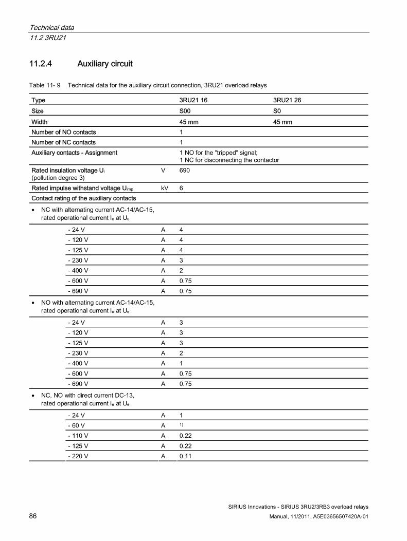
Technical data 11.2 3RU21
SIRIUS Innovations - SIRIUS 3RU2/3RB3 overload relays
86 Manual, 11/2011, A5E03656507420A-01
11.2.4 Auxiliary circuit
Table 11- 9 Technical data for the auxiliary circuit connection, 3RU21 overload relays
Type 3RU21 16 3RU21 26 Size S00 S0
Width 45 mm 45 mm Number of NO contacts 1 Number of NC contacts 1 Auxiliary contacts - Assignment 1 NO for the "tripped" signal;
1 NC for disconnecting the contactor Rated insulation voltage Ui (pollution degree 3)
V 690
Rated impulse withstand voltage Uimp kV 6 Contact rating of the auxiliary contacts
• NC with alternating current AC-14/AC-15, rated operational current Ie at Ue
- 24 V A 4 - 120 V A 4 - 125 V A 4 - 230 V A 3 - 400 V A 2 - 600 V A 0.75
- 690 V A 0.75
• NO with alternating current AC-14/AC-15, rated operational current Ie at Ue
- 24 V A 3 - 120 V A 3 - 125 V A 3 - 230 V A 2 - 400 V A 1 - 600 V A 0.75
- 690 V A 0.75
• NC, NO with direct current DC-13, rated operational current Ie at Ue
- 24 V A 1 - 60 V A 1) - 110 V A 0.22 - 125 V A 0.22
- 220 V A 0.11
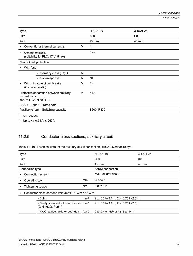
Technical data 11.2 3RU21
SIRIUS Innovations - SIRIUS 3RU2/3RB3 overload relays
Manual, 11/2011, A5E03656507420A-01 87
Type 3RU21 16 3RU21 26
Size S00 S0 Width 45 mm 45 mm
• Conventional thermal current Ith A 6
• Contact reliability (suitability for PLC, 17 V, 5 mA)
Yes
Short-circuit protection
• With fuse
- Operating class gL/gG A 6 - Quick-response A 10
• With miniature circuit breaker (C characteristic)
A 62)
Protective separation between auxiliary current paths acc. to IEC/EN 60947-1
V 440
CSA, UL, and UR rated data Auxiliary circuit – Switching capacity B600, R300
1) On request 2) Up to Ik≤ 0.5 kA; ≤ 260 V
11.2.5 Conductor cross sections, auxiliary circuit
Table 11- 10 Technical data for the auxiliary circuit connection, 3RU21 overload relays
Type 3RU21 16 3RU21 26 Size S00 S0
Width 45 mm 45 mm Connection type Screw connection
• Connection screw M3, Pozidriv size 2
• Operating tool mm ∅ 5 to 6
• Tightening torque Nm 0.8 to 1.2
• Conductor cross-sections (min./max.), 1-wire or 2-wire
- Solid mm2 2 x (0.5 to 1.5)1); 2 x (0.75 to 2.5)1) - Finely stranded with end sleeve (DIN 46228 Part 1)
mm2 2 x (0.5 to 1.5)1); 2 x (0.75 to 2.5)1)
- AWG cables, solid or stranded AWG 2 x (20 to 16)1), 2 x (18 to 14)1)
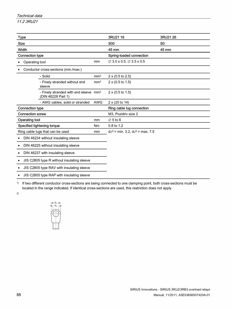
Technical data 11.2 3RU21
SIRIUS Innovations - SIRIUS 3RU2/3RB3 overload relays
88 Manual, 11/2011, A5E03656507420A-01
Type 3RU21 16 3RU21 26
Size S00 S0 Width 45 mm 45 mm Connection type Spring-loaded connection
• Operating tool mm ∅ 3.0 x 0.5. ∅ 3.5 x 0.5
• Conductor cross-sections (min./max.)
- Solid mm2 2 x (0.5 to 2.5) - Finely stranded without end sleeve
mm2 2 x (0.5 to 1.5)
- Finely stranded with end sleeve (DIN 46228 Part 1)
mm2 2 x (0.5 to 1.5)
- AWG cables, solid or stranded AWG 2 x (20 to 14) Connection type Ring cable lug connection Connection screw M3, Pozidriv size 2 Operating tool mm ∅ 5 to 6 Specified tightening torque Nm 0.8 to 1.2 Ring cable lugs that can be used mm
• DIN 46234 without insulating sleeve
• DIN 46225 without insulating sleeve
• DIN 46237 with insulating sleeve
• JIS C2805 type R without insulating sleeve
• JIS C2805 type RAV with insulating sleeve
• JIS C2805 type RAP with insulating sleeve
d22) = min. 3.2, d32) = max. 7.5
1) If two different conductor cross-sections are being connected to one clamping point, both cross-sections must be located in the range indicated. If identical cross-sections are used, this restriction does not apply.
2)
d2d3
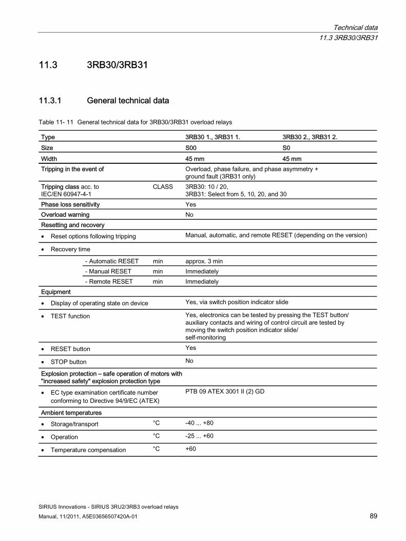
Technical data 11.3 3RB30/3RB31
SIRIUS Innovations - SIRIUS 3RU2/3RB3 overload relays
Manual, 11/2011, A5E03656507420A-01 89
11.3 3RB30/3RB31
11.3.1 General technical data
Table 11- 11 General technical data for 3RB30/3RB31 overload relays
Type 3RB30 1., 3RB31 1. 3RB30 2., 3RB31 2. Size S00 S0
Width 45 mm 45 mm Tripping in the event of Overload, phase failure, and phase asymmetry +
ground fault (3RB31 only) Tripping class acc. to IEC/EN 60947-4-1
CLASS 3RB30: 10 / 20, 3RB31: Select from 5, 10, 20, and 30
Phase loss sensitivity Yes Overload warning No Resetting and recovery
• Reset options following tripping Manual, automatic, and remote RESET (depending on the version)
• Recovery time
- Automatic RESET min approx. 3 min - Manual RESET min Immediately
- Remote RESET min Immediately Equipment
• Display of operating state on device Yes, via switch position indicator slide
• TEST function Yes, electronics can be tested by pressing the TEST button/ auxiliary contacts and wiring of control circuit are tested by moving the switch position indicator slide/ self-monitoring
• RESET button Yes
• STOP button No
Explosion protection – safe operation of motors with "increased safety" explosion protection type
• EC type examination certificate number conforming to Directive 94/9/EC (ATEX)
PTB 09 ATEX 3001 II (2) GD
Ambient temperatures
• Storage/transport °C -40 ... +80
• Operation °C -25 ... +60
• Temperature compensation °C +60
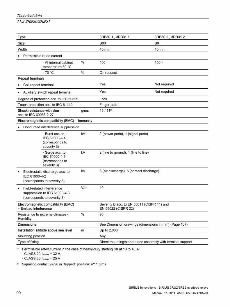
Technical data 11.3 3RB30/3RB31
SIRIUS Innovations - SIRIUS 3RU2/3RB3 overload relays
90 Manual, 11/2011, A5E03656507420A-01
Type 3RB30 1., 3RB31 1. 3RB30 2., 3RB31 2.
Size S00 S0 Width 45 mm 45 mm
• Permissible rated current
- At internal cabinet temperature 60 °C
% 100 1001)
- 70 °C % On request Repeat terminals
• Coil repeat terminal Yes Not required
• Auxiliary switch repeat terminal Yes Not required
Degree of protection acc. to IEC 60529 IP20 Touch protection acc. to IEC 61140 Finger-safe Shock resistance with sine acc. to IEC 60068-2-27
g/ms 15 / 112)
Electromagnetic compatibility (EMC) - Immunity
• Conducted interference suppression
- Burst acc. to IEC 61000-4-4 (corresponds to severity 3)
kV 2 (power ports), 1 (signal ports)
- Surge acc. to IEC 61000-4-5 (corresponds to severity 3)
kV 2 (line to ground), 1 (line to line)
• Electrostatic discharge acc. to IEC 61000-4-2 (corresponds to severity 3)
kV 8 (air discharge), 6 (contact discharge)
• Field-related interference suppression to IEC 61000-4-3 (corresponds to severity 3)
V/m 10
Electromagnetic compatibility (EMC) – Emitted interference
Severity B acc. to EN 55011 (CISPR 11) and EN 55022 (CISPR 22)
Resistance to extreme climates - Humidity
% 95
Dimensions See Dimension drawings (dimensions in mm) (Page 107) Installation altitude above sea level m Up to 2,000 Mounting position Any Type of fixing Direct mounting/stand-alone assembly with terminal support
1) Permissible rated current in the case of heavy-duty starting S0 at 10 to 40 A: - CLASS 20, Iemax = 32 A, - CLASS 30, Iemax = 25 A
2) Signaling contact 97/98 in "tripped" position: 4/11 g/ms
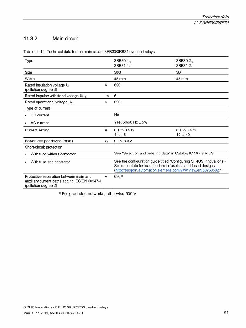
Technical data 11.3 3RB30/3RB31
SIRIUS Innovations - SIRIUS 3RU2/3RB3 overload relays
Manual, 11/2011, A5E03656507420A-01 91
11.3.2 Main circuit
Table 11- 12 Technical data for the main circuit, 3RB30/3RB31 overload relays
Type 3RB30 1., 3RB31 1.
3RB30 2., 3RB31 2.
Size S00 S0
Width 45 mm 45 mm Rated insulation voltage Ui (pollution degree 3)
V 690
Rated impulse withstand voltage Uimp kV 6 Rated operational voltage Ue V 690 Type of current
• DC current No
• AC current Yes, 50/60 Hz ± 5%
Current setting A 0.1 to 0.4 to 4 to 16
0.1 to 0.4 to 10 to 40
Power loss per device (max.) W 0.05 to 0.2 Short-circuit protection
• With fuse without contactor See "Selection and ordering data" in Catalog IC 10 - SIRIUS
• With fuse and contactor See the configuration guide titled "Configuring SIRIUS Innovations - Selection data for load feeders in fuseless and fused designs (http://support.automation.siemens.com/WW/view/en/50250592)".
Protective separation between main and auxiliary current paths acc. to IEC/EN 60947-1 (pollution degree 2)
V 6901)
1) For grounded networks, otherwise 600 V
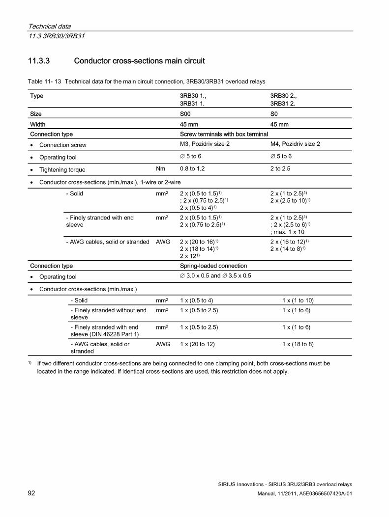
Technical data 11.3 3RB30/3RB31
SIRIUS Innovations - SIRIUS 3RU2/3RB3 overload relays
92 Manual, 11/2011, A5E03656507420A-01
11.3.3 Conductor cross-sections main circuit
Table 11- 13 Technical data for the main circuit connection, 3RB30/3RB31 overload relays
Type 3RB30 1., 3RB31 1.
3RB30 2., 3RB31 2.
Size S00 S0
Width 45 mm 45 mm Connection type Screw terminals with box terminal
• Connection screw M3, Pozidriv size 2 M4, Pozidriv size 2
• Operating tool ∅ 5 to 6 ∅ 5 to 6
• Tightening torque Nm 0.8 to 1.2 2 to 2.5
• Conductor cross-sections (min./max.), 1-wire or 2-wire
- Solid mm2 2 x (0.5 to 1.5)1) ; 2 x (0.75 to 2.5)1)
2 x (0.5 to 4)1)
2 x (1 to 2.5)1) 2 x (2.5 to 10)1)
- Finely stranded with end sleeve
mm2 2 x (0.5 to 1.5)1) 2 x (0.75 to 2.5)1)
2 x (1 to 2.5)1) ; 2 x (2.5 to 6)1)
; max. 1 x 10
- AWG cables, solid or stranded AWG 2 x (20 to 16)1) 2 x (18 to 14)1) 2 x 121)
2 x (16 to 12)1)
2 x (14 to 8)1)
Connection type Spring-loaded connection
• Operating tool ∅ 3.0 x 0.5 and ∅ 3.5 x 0.5
• Conductor cross-sections (min./max.)
- Solid mm2 1 x (0.5 to 4) 1 x (1 to 10) - Finely stranded without end sleeve
mm2 1 x (0.5 to 2.5) 1 x (1 to 6)
- Finely stranded with end sleeve (DIN 46228 Part 1)
mm2 1 x (0.5 to 2.5) 1 x (1 to 6)
- AWG cables, solid or stranded
AWG 1 x (20 to 12) 1 x (18 to 8)
1) If two different conductor cross-sections are being connected to one clamping point, both cross-sections must be located in the range indicated. If identical cross-sections are used, this restriction does not apply.
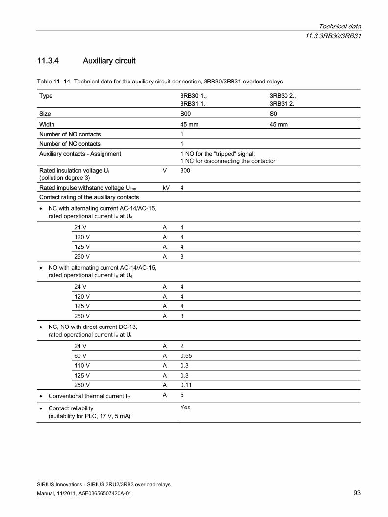
Technical data 11.3 3RB30/3RB31
SIRIUS Innovations - SIRIUS 3RU2/3RB3 overload relays
Manual, 11/2011, A5E03656507420A-01 93
11.3.4 Auxiliary circuit
Table 11- 14 Technical data for the auxiliary circuit connection, 3RB30/3RB31 overload relays
Type 3RB30 1., 3RB31 1.
3RB30 2., 3RB31 2.
Size S00 S0
Width 45 mm 45 mm Number of NO contacts 1 Number of NC contacts 1 Auxiliary contacts - Assignment 1 NO for the "tripped" signal;
1 NC for disconnecting the contactor Rated insulation voltage Ui (pollution degree 3)
V 300
Rated impulse withstand voltage Uimp kV 4 Contact rating of the auxiliary contacts
• NC with alternating current AC-14/AC-15, rated operational current Ie at Ue
24 V A 4 120 V A 4 125 V A 4
250 V A 3
• NO with alternating current AC-14/AC-15, rated operational current Ie at Ue
24 V A 4 120 V A 4 125 V A 4
250 V A 3
• NC, NO with direct current DC-13, rated operational current Ie at Ue
24 V A 2 60 V A 0.55 110 V A 0.3 125 V A 0.3
250 V A 0.11
• Conventional thermal current Ith A 5
• Contact reliability (suitability for PLC, 17 V, 5 mA)
Yes
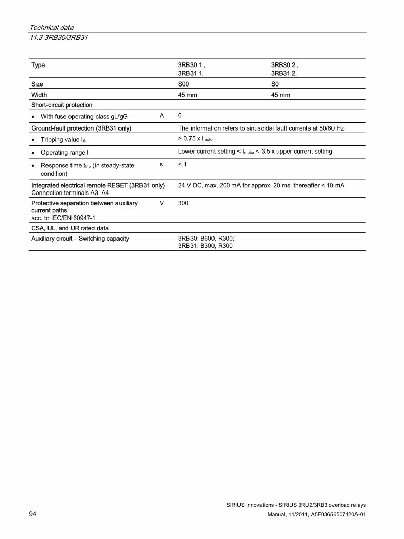
Technical data 11.3 3RB30/3RB31
SIRIUS Innovations - SIRIUS 3RU2/3RB3 overload relays
94 Manual, 11/2011, A5E03656507420A-01
Type 3RB30 1., 3RB31 1.
3RB30 2., 3RB31 2.
Size S00 S0 Width 45 mm 45 mm Short-circuit protection
• With fuse operating class gL/gG A 6
Ground-fault protection (3RB31 only) The information refers to sinusoidal fault currents at 50/60 Hz
• Tripping value IΔ > 0.75 x Imotor
• Operating range I Lower current setting < Imotor < 3.5 x upper current setting
• Response time ttrip (in steady-state condition)
s < 1
Integrated electrical remote RESET (3RB31 only) Connection terminals A3, A4
24 V DC, max. 200 mA for approx. 20 ms, thereafter < 10 mA
Protective separation between auxiliary current paths acc. to IEC/EN 60947-1
V 300
CSA, UL, and UR rated data Auxiliary circuit – Switching capacity 3RB30: B600, R300;
3RB31: B300, R300
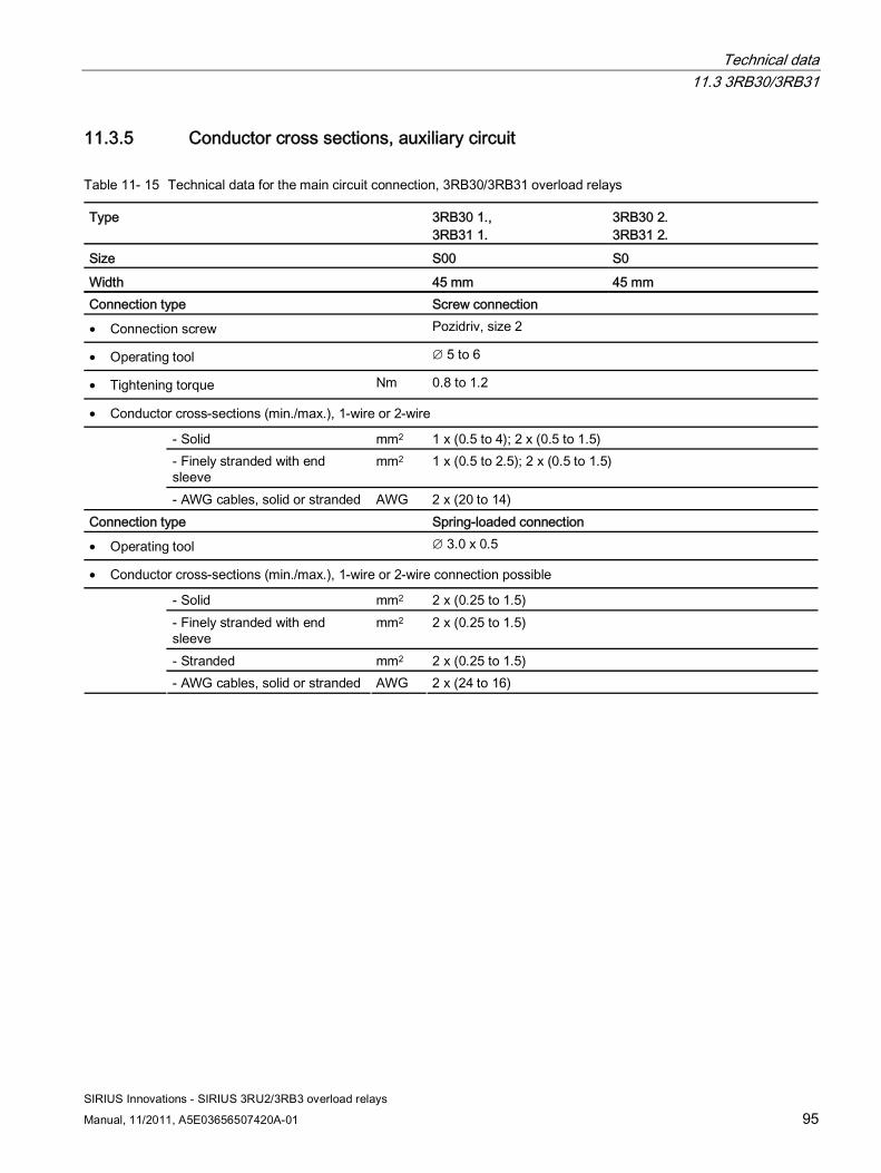
Technical data 11.3 3RB30/3RB31
SIRIUS Innovations - SIRIUS 3RU2/3RB3 overload relays
Manual, 11/2011, A5E03656507420A-01 95
11.3.5 Conductor cross sections, auxiliary circuit
Table 11- 15 Technical data for the main circuit connection, 3RB30/3RB31 overload relays
Type 3RB30 1., 3RB31 1.
3RB30 2. 3RB31 2.
Size S00 S0
Width 45 mm 45 mm Connection type Screw connection
• Connection screw Pozidriv, size 2
• Operating tool ∅ 5 to 6
• Tightening torque Nm 0.8 to 1.2
• Conductor cross-sections (min./max.), 1-wire or 2-wire
- Solid mm2 1 x (0.5 to 4); 2 x (0.5 to 1.5) - Finely stranded with end sleeve
mm2 1 x (0.5 to 2.5); 2 x (0.5 to 1.5)
- AWG cables, solid or stranded AWG 2 x (20 to 14) Connection type Spring-loaded connection
• Operating tool ∅ 3.0 x 0.5
• Conductor cross-sections (min./max.), 1-wire or 2-wire connection possible
- Solid mm2 2 x (0.25 to 1.5) - Finely stranded with end sleeve
mm2 2 x (0.25 to 1.5)
- Stranded mm2 2 x (0.25 to 1.5)
- AWG cables, solid or stranded AWG 2 x (24 to 16)

Technical data 11.3 3RB30/3RB31
SIRIUS Innovations - SIRIUS 3RU2/3RB3 overload relays
96 Manual, 11/2011, A5E03656507420A-01
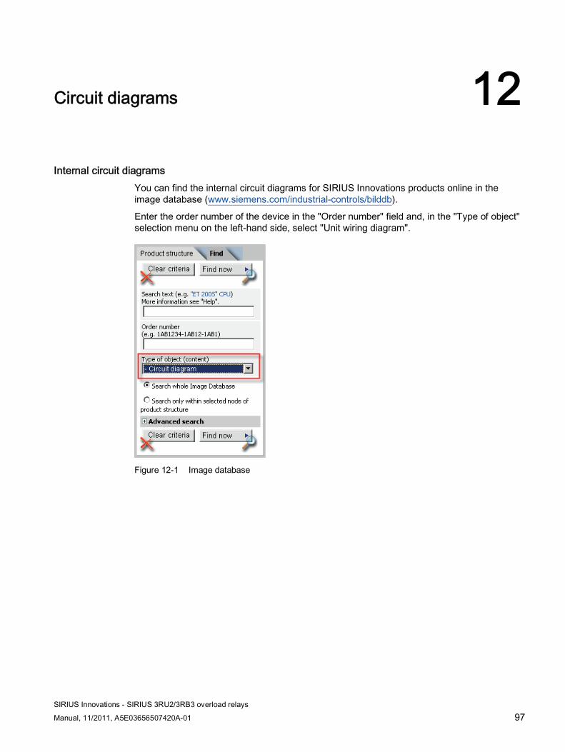
SIRIUS Innovations - SIRIUS 3RU2/3RB3 overload relays
Manual, 11/2011, A5E03656507420A-01 97
Circuit diagrams 12
Internal circuit diagrams You can find the internal circuit diagrams for SIRIUS Innovations products online in the image database (www.siemens.com/industrial-controls/bilddb).
Enter the order number of the device in the "Order number" field and, in the "Type of object" selection menu on the left-hand side, select "Unit wiring diagram".
Figure 12-1 Image database
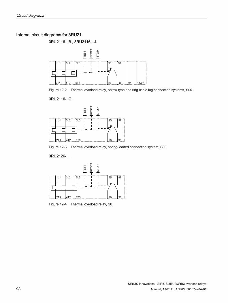
Circuit diagrams
SIRIUS Innovations - SIRIUS 3RU2/3RB3 overload relays
98 Manual, 11/2011, A5E03656507420A-01
Internal circuit diagrams for 3RU21 3RU2116-..B., 3RU2116-..J.
Figure 12-2 Thermal overload relay, screw-type and ring cable lug connection systems, S00
3RU2116-..C.
Figure 12-3 Thermal overload relay, spring-loaded connection system, S00
3RU2126-....
Figure 12-4 Thermal overload relay, S0
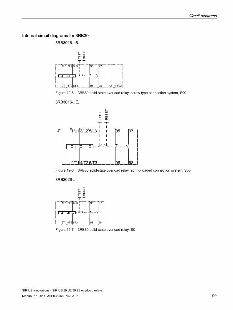
Circuit diagrams
SIRIUS Innovations - SIRIUS 3RU2/3RB3 overload relays
Manual, 11/2011, A5E03656507420A-01 99
Internal circuit diagrams for 3RB30 3RB3016-..B.
Figure 12-5 3RB30 solid-state overload relay, screw-type connection system, S00
3RB3016-..E.
Figure 12-6 3RB30 solid-state overload relay, spring-loaded connection system, S00
3RB3026-....
Figure 12-7 3RB30 solid-state overload relay, S0
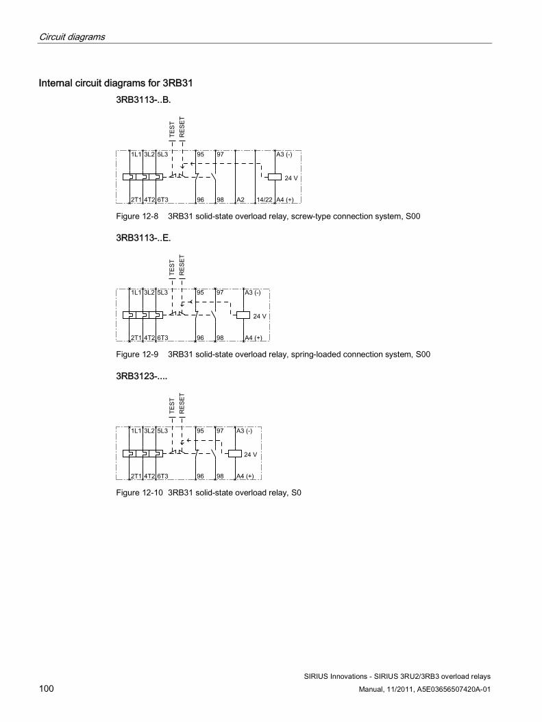
Circuit diagrams
SIRIUS Innovations - SIRIUS 3RU2/3RB3 overload relays
100 Manual, 11/2011, A5E03656507420A-01
Internal circuit diagrams for 3RB31 3RB3113-..B.
Figure 12-8 3RB31 solid-state overload relay, screw-type connection system, S00
3RB3113-..E.
Figure 12-9 3RB31 solid-state overload relay, spring-loaded connection system, S00
3RB3123-....
Figure 12-10 3RB31 solid-state overload relay, S0
SIRIUS Innovations - SIRIUS 3RU2/3RB3 overload relays
Manual, 11/2011, A5E03656507420A-01 101
Types of coordination A
Types of coordination Standard DIN EN 60947-4-1 (VDE 0660 Part 102) or IEC 60947-4-1 distinguishes between two types of coordination (type of coordination), which are referred to as coordination type "1" and coordination type "2". The short circuit that needs to be dealt with is cleared reliably and safely with both types of coordination; the only differences are in the extent of the damage sustained by the device following a short circuit.
Type of coordination 1 It is permissible for the fuseless load feeder to be incapable of functioning after each short-circuit disconnection. Damage to the contactor and the overload release is also permissible. For 3RA2, the motor starter protector alone always achieves type of coordination "2".
Type of coordination 2 After short-circuit disconnection, there must be no damage to the overload release or to any other part. The 3RA2 fuseless load feeder can resume operation without any parts having to be repaired or replaced. Welding of the contactor contacts only is permitted if these can be separated easily without significant deformation.

Types of coordination
SIRIUS Innovations - SIRIUS 3RU2/3RB3 overload relays
102 Manual, 11/2011, A5E03656507420A-01
SIRIUS Innovations - SIRIUS 3RU2/3RB3 overload relays
Manual, 11/2011, A5E03656507420A-01 103
References BB.1 References
Further references You will find further information on the 3RU2/3RB3 overload relays Hotspot-Text (http://support.automation.siemens.com/WW/view/en/20357459/133300) on the Internet.
In addition to this manual, please refer to the operating instructions and manuals for any accessories. You can download the relevant documentation from the Internet (www.siemens.com/industrial-controls/manuals). Simply enter the order number of the relevant item into the search field.
Operating instructions Title Order number S00/S0 (3RU2116... and 3RU2126...) SIRIUS overload relays 3ZX1012-0RU21-1AA1 S00/S0 (3RB30 and 3RB31) SIRIUS solid-state overload relay 3ZX1012-0RB30-1AA1
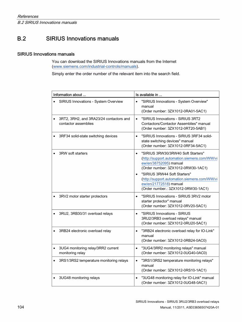
References B.2 SIRIUS Innovations manuals
SIRIUS Innovations - SIRIUS 3RU2/3RB3 overload relays
104 Manual, 11/2011, A5E03656507420A-01
B.2 SIRIUS Innovations manuals
SIRIUS Innovations manuals You can download the SIRIUS Innovations manuals from the Internet (www.siemens.com/industrial-controls/manuals).
Simply enter the order number of the relevant item into the search field.
Information about ... Is available in ...
• SIRIUS Innovations - System Overview • "SIRIUS Innovations - System Overview" manual (Order number: 3ZX1012-0RA01-5AC1)
• 3RT2, 3RH2, and 3RA23/24 contactors and contactor assemblies
• "SIRIUS Innovations - SIRIUS 3RT2 Contactors/Contactor Assemblies" manual (Order number: 3ZX1012-0RT20-5AB1)
• 3RF34 solid-state switching devices • "SIRIUS Innovations - SIRIUS 3RF34 solid-state switching devices" manual (Order number: 3ZX1012-0RF34-5AC1)
• 3RW soft starters • "SIRIUS 3RW30/3RW40 Soft Starters" (http://support.automation.siemens.com/WW/view/en/38752095) manual (Order number: 3ZX1012-0RW30-1AC1)
• "SIRIUS 3RW44 Soft Starters" (http://support.automation.siemens.com/WW/view/en/21772518) manual (Order number.: 3ZX1012-0RW30-1AC1)
• 3RV2 motor starter protectors • "SIRIUS Innovations - SIRIUS 3RV2 motor starter protector" manual (Order number: 3ZX1012-0RV20-5AC1)
• 3RU2, 3RB30/31 overload relays • "SIRIUS Innovations - SIRIUS 3RU2/3RB3 overload relays" manual (Order number: 3ZX1012-0RU20-5AC1)
• 3RB24 electronic overload relay • "3RB24 electronic overload relay for IO-Link" manual (Order number: 3ZX1012-0RB24-0AC0)
• 3UG4 monitoring relay/3RR2 current monitoring relay
• "3UG4/3RR2 monitoring relays" manual (Order number: 3ZX1012-0UG40-0AC0)
• 3RS1/3RS2 temperature monitoring relays • "3RS1/3RS2 temperature monitoring relays" manual (Order number: 3ZX1012-0RS10-1AC1)
• 3UG48 monitoring relays • "3UG48 monitoring relay for IO-Link" manual (Order number: 3ZX1012-0UG48-0AC1)
References B.2 SIRIUS Innovations manuals
SIRIUS Innovations - SIRIUS 3RU2/3RB3 overload relays
Manual, 11/2011, A5E03656507420A-01 105
Information about ... Is available in ...
• 3RS14/3RS15 temperature monitoring relays • "3RS14/3RS15 temperature monitoring relay for IO-Link" manual (Order number: 3ZX1012-0RS14-0AC0)
• 3RA21/22 load feeders • "SIRIUS Innovations - SIRIUS 3RA21/3RA22 load feeders" manual (Order number: 3ZX1012-0RA21-5AC1)
• 3RA6 compact starters • "SIRIUS 3RA6 Compact Starter" (http://support.automation.siemens.com/WW/view/en/27865747) manual (order number: 3RA6992-0A)
• 3RA28 function modules for mounting on contactors
• "SIRIUS Innovations - SIRIUS 3RA28 function modules for mounting on 3RT2 contactors" (Order number: 3ZX1012-0RA28-5AC1)
• 3RA27 function modules for connection to the higher-level control
• "Function Modules for AS-Interface" (http://support.automation.siemens.com/WW/view/en/39318922) manual (order number: 3ZX1012-0RA27-0AC0)
• "Function Modules for IO-Link" (http://support.automation.siemens.com/WW/view/en/39319600) manual (order number: 3ZX1012-0RA27-1AC1)
• 4SI SIRIUS electronic module (3RK1005-0LB00-0AA0)"
• "4SI SIRIUS electronic module (3RK1005-0LB00-0AA0)" manual (Order number:3ZX1012-0LB00-0AA1)

References B.3 More information
SIRIUS Innovations - SIRIUS 3RU2/3RB3 overload relays
106 Manual, 11/2011, A5E03656507420A-01
B.3 More information
More information More information is available from Siemens on the Internet via the following links.
● Product documentation You will find a list of manuals/operating instructions, characteristic curves, and certificates on the Internet (www.siemens.com/industrial-controls/support).
● Product information Catalogs and other informative documents can be obtained from the Information Center and Download Center (www.siemens.com/industrial-controls/infomaterial).
● Online ordering system You will find the online ordering system with all the latest data on the ordering and information platform (www.siemens.com/industrial-controls/mall).
● Technical Assistance Siemens supports you with all technical product and system enquiries – both before and after delivery. You can access our Service & Support Portal on the Internet (www.siemens.com/industrial-controls/technical-assistance). You can also submit your question directly to a technical consultant using our support request service.
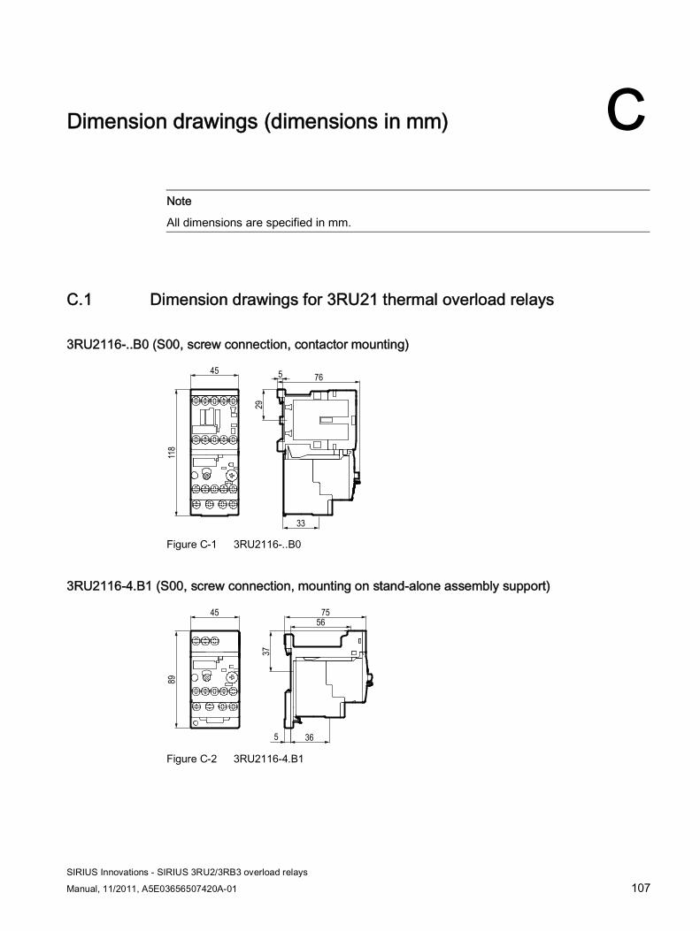
SIRIUS Innovations - SIRIUS 3RU2/3RB3 overload relays
Manual, 11/2011, A5E03656507420A-01 107
Dimension drawings (dimensions in mm) C
Note
All dimensions are specified in mm.
C.1 Dimension drawings for 3RU21 thermal overload relays
3RU2116-..B0 (S00, screw connection, contactor mounting)
765
29
33
45
118
Figure C-1 3RU2116-..B0
3RU2116-4.B1 (S00, screw connection, mounting on stand-alone assembly support)
75
5
37
56
36
45
89
Figure C-2 3RU2116-4.B1

Dimension drawings (dimensions in mm) C.1 Dimension drawings for 3RU21 thermal overload relays
SIRIUS Innovations - SIRIUS 3RU2/3RB3 overload relays
108 Manual, 11/2011, A5E03656507420A-01
3RU2116-..C0 (S00, spring-loaded connection, contactor mounting)
94
355
64
45
140
Figure C-3 3RU2116-..C0
3RU2116-..C1 (S00, spring-loaded connection, mounting on stand-alone assembly support)
80
51
5
60
56
45
102
Figure C-4 3RU2116-..C1
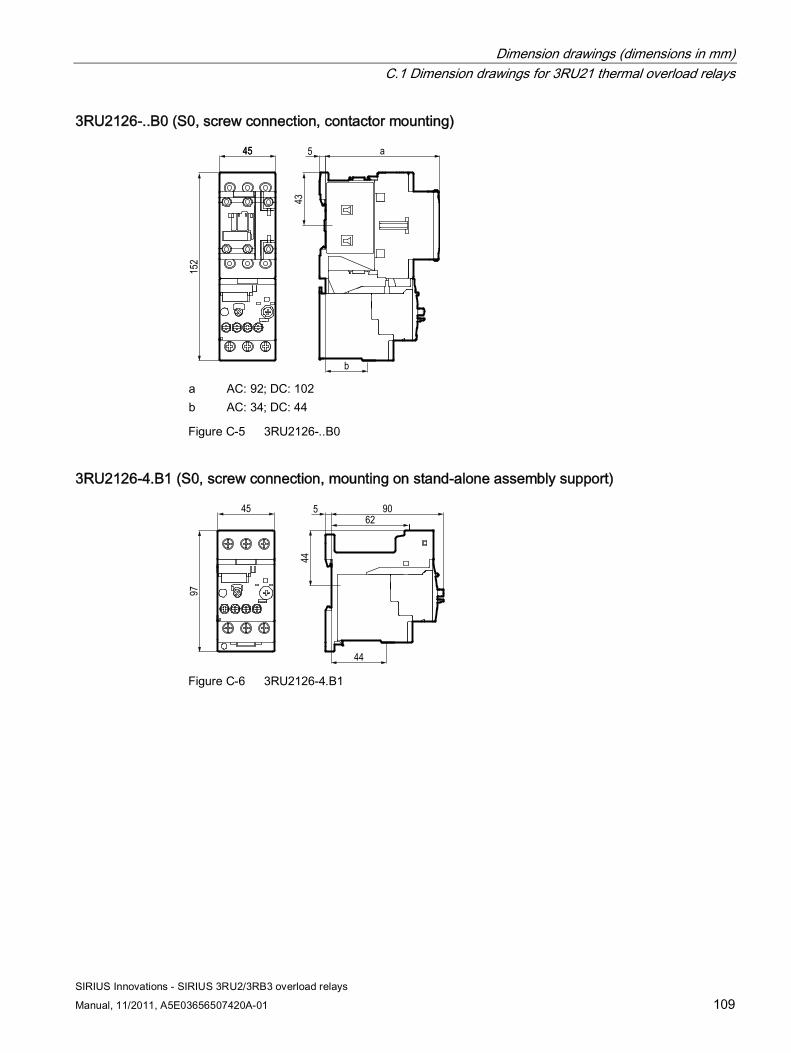
Dimension drawings (dimensions in mm) C.1 Dimension drawings for 3RU21 thermal overload relays
SIRIUS Innovations - SIRIUS 3RU2/3RB3 overload relays
Manual, 11/2011, A5E03656507420A-01 109
3RU2126-..B0 (S0, screw connection, contactor mounting)
43
5 a
152
4545
b a AC: 92; DC: 102 b AC: 34; DC: 44
Figure C-5 3RU2126-..B0
3RU2126-4.B1 (S0, screw connection, mounting on stand-alone assembly support)
44
5 90
97
4562
44 Figure C-6 3RU2126-4.B1
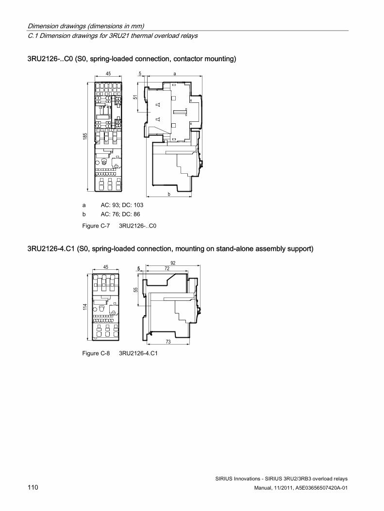
Dimension drawings (dimensions in mm) C.1 Dimension drawings for 3RU21 thermal overload relays
SIRIUS Innovations - SIRIUS 3RU2/3RB3 overload relays
110 Manual, 11/2011, A5E03656507420A-01
3RU2126-..C0 (S0, spring-loaded connection, contactor mounting)
5
51
185
45 a
b a AC: 93; DC: 103 b AC: 76; DC: 86
Figure C-7 3RU2126-..C0
3RU2126-4.C1 (S0, spring-loaded connection, mounting on stand-alone assembly support)
55
5592
114
45 72
73 Figure C-8 3RU2126-4.C1
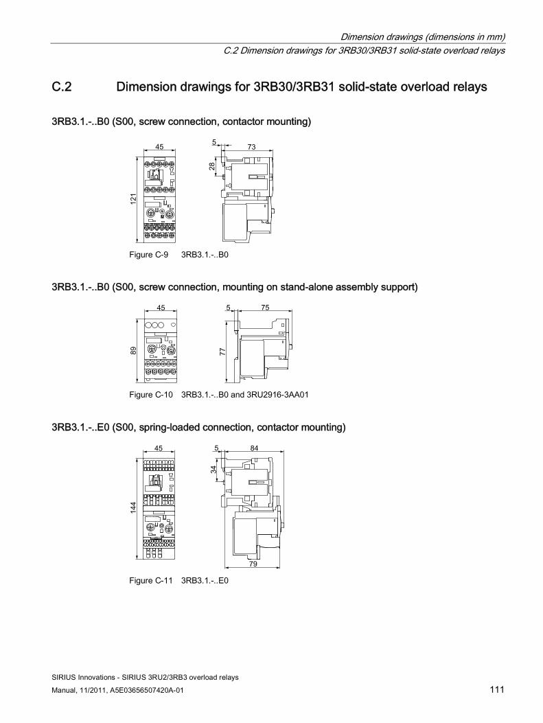
Dimension drawings (dimensions in mm) C.2 Dimension drawings for 3RB30/3RB31 solid-state overload relays
SIRIUS Innovations - SIRIUS 3RU2/3RB3 overload relays
Manual, 11/2011, A5E03656507420A-01 111
C.2 Dimension drawings for 3RB30/3RB31 solid-state overload relays
3RB3.1.-..B0 (S00, screw connection, contactor mounting)
Figure C-9 3RB3.1.-..B0
3RB3.1.-..B0 (S00, screw connection, mounting on stand-alone assembly support)
Figure C-10 3RB3.1.-..B0 and 3RU2916-3AA01
3RB3.1.-..E0 (S00, spring-loaded connection, contactor mounting)
Figure C-11 3RB3.1.-..E0
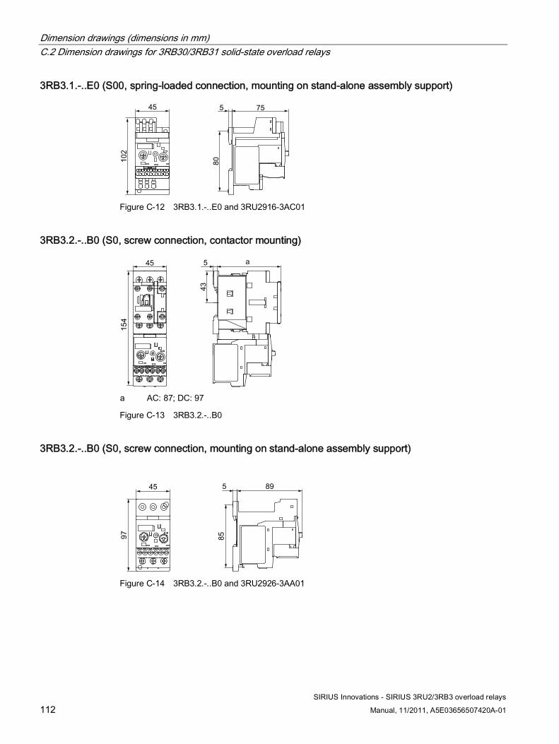
Dimension drawings (dimensions in mm) C.2 Dimension drawings for 3RB30/3RB31 solid-state overload relays
SIRIUS Innovations - SIRIUS 3RU2/3RB3 overload relays
112 Manual, 11/2011, A5E03656507420A-01
3RB3.1.-..E0 (S00, spring-loaded connection, mounting on stand-alone assembly support)
Figure C-12 3RB3.1.-..E0 and 3RU2916-3AC01
3RB3.2.-..B0 (S0, screw connection, contactor mounting)
a AC: 87; DC: 97
Figure C-13 3RB3.2.-..B0
3RB3.2.-..B0 (S0, screw connection, mounting on stand-alone assembly support)
Figure C-14 3RB3.2.-..B0 and 3RU2926-3AA01
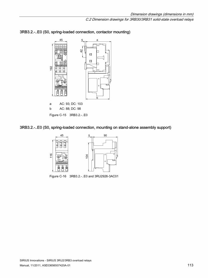
Dimension drawings (dimensions in mm) C.2 Dimension drawings for 3RB30/3RB31 solid-state overload relays
SIRIUS Innovations - SIRIUS 3RU2/3RB3 overload relays
Manual, 11/2011, A5E03656507420A-01 113
3RB3.2.-..E0 (S0, spring-loaded connection, contactor mounting)
a AC: 93; DC: 103 b AC: 88; DC: 98
Figure C-15 3RB3.2.-..E0
3RB3.2.-..E0 (S0, spring-loaded connection, mounting on stand-alone assembly support)
Figure C-16 3RB3.2.-..E0 and 3RU2926-3AC01

Dimension drawings (dimensions in mm) C.2 Dimension drawings for 3RB30/3RB31 solid-state overload relays
SIRIUS Innovations - SIRIUS 3RU2/3RB3 overload relays
114 Manual, 11/2011, A5E03656507420A-01

SIRIUS Innovations - SIRIUS 3RU2/3RB3 overload relays
Manual, 11/2011, A5E03656507420A-01 115
Correction sheet D
Correction sheet Have you noticed any errors while reading this manual? If so, please use this form to tell us about them. We welcome comments and suggestions for improvement.
Fax response
From (please complete): To SIEMENS AG I IA CE MK&ST 3 92220 Amberg/Germany
Name Company/Department Address
_________________________________________________________________________________
Fax: +49 (0)9621-80-3337
Manual title:
Table D- 1 Errors, comments, and suggestions for improvements

Correction sheet
SIRIUS Innovations - SIRIUS 3RU2/3RB3 overload relays
116 Manual, 11/2011, A5E03656507420A-01

SIRIUS Innovations - SIRIUS 3RU2/3RB3 overload relays
Manual, 11/2011, A5E03656507420A-01 117
Index
A Accessories
Overload relay, 65 Accessories - Overload relays
Cable release, 70, 71 Cover for ring cable lug, 76 Mechanical remote RESET, 68, 69, 70, 71 Module for electrical remote RESET, 72, 73 Release slide, 68, 69 Sealable cover, 74, 75 Terminal support for stand-alone assembly, 65, 66
Advantages Overload relay, 18
Ambient temperature Overload relay, 40, 40
Applications Overload relay, 17
Auxiliary contacts (overload relay), 63 Auxiliary switch
Overload relay, 31, 47
B Basic knowledge, 10
C Cable release
Overload relay, 70, 71 Coil terminal
Overload relay, 47 Connection systems
Overload relay, 16, 47 Contactor assemblies for star-delta (wye-delta) start
Overload relay, 30, 38 Correction sheet, 115 Corrections, 11 Cover for ring cable lug
Overload relay, 76
D DC loads
Overload relay, 25 Derating
Overload relay, 40 Device versions
Overload relay, 16 Disposal, 10
E Equipment features
Overload relay, 19, 21 Explosion protection
Overload relay, 39
F Finger-safety
Overload relay, 76 Frequency converter
Overload relay, 38
G Ground fault
Overload relay, 30, 32, 38
H Heavy-duty starting
Overload relay, 26, 37
I Innovations, 104 Internal circuit diagrams, 97
Overload relay, 98, 99, 100
Index
SIRIUS Innovations - SIRIUS 3RU2/3RB3 overload relays
118 Manual, 11/2011, A5E03656507420A-01
M Mechanical remote RESET
Overload relay, 68, 69, 70, 71 Minimum clearance
Overload relay, 41 Module for electrical remote RESET
Overload relay, 72, 73 Motor feeder (overload relay)
Design, 36 Mounting position
Overload relay, 41
N Normal starting
Overload relay, 26, 37
O Operating instructions, 103 Overload
Overload relay, 26, 32
P Phase asymmetry
Overload relay, 29, 32 Phase failure
Overload relay, 26, 32
R Recovery time
Overload relay, 59 Recycling, 10 References, 103 Release slide
Overload relay, 68, 69 RESET
Overload relay, 33, 59, 60 Ring cable lug connection system, 54
S Scope of validity
Manual, 10 Screw mounting
Overload relay, 44
Screw-type connection system, 50 Sealable cover
Overload relay, 74, 75 Setting ground-fault detection
Overload relay, 58 Setting the tripping class
Overload relay, 58 Short-circuit protection
Overload relay, 39 Single-phase load
Overload relay, 25 SIRIUS Innovations system configurator, 35 Snap-on mounting
Overload relay, 44 Spring-loaded connection system, 52 Standards
Overload relay, 13
T Technical Assistance, 11 Terminal designations
Overload relay, 48, 49 Terminal support for stand-alone assembly
Overload relay, 65, 66 Test function
Overload relay, 33, 61, 62 Three-phase current loads
Overload relay, 36 Touch protection
Overload relay, 47 Tripping characteristics
Overload relay, 28, 29 Tripping classes
Overload relay, 26 Types of coordination, 101
Overload relay, 37, 39

www.siemens.com/automation
Subject to change without prior noticeOrder No.: 3ZX1012-0RU20-5AC1
© Siemens AG 2011
Siemens AGIndustry SectorPostfach 23 5590713 FUERTHGERMANY
Service & Support
Download catalogs and information material:www.siemens.com/industrial-controls/catalogs
Newsletter - always up to date:www.siemens.com/industrial-controls/newsletter
E-Business in the Industry Mall:www.siemens.com/industrial-controls/mall
Online-Support:www.siemens.com/industrial-controls/support
Contact for all technical information:Technical AssistanceTel.: +49 (911) 895-5900e-mail: [email protected]/industrial-controls/technical-assistance