Embed Size (px)
Citation preview
Mr Downie 2014 1

Mr Downie 2014 2
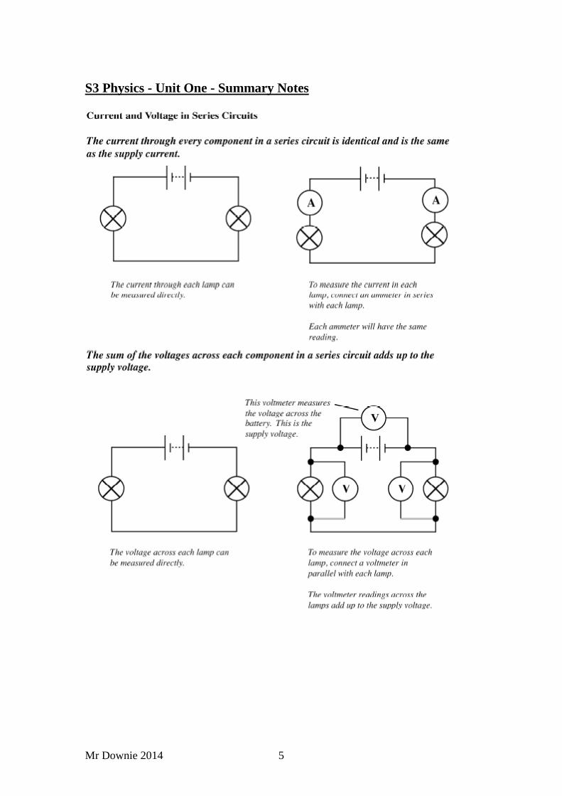
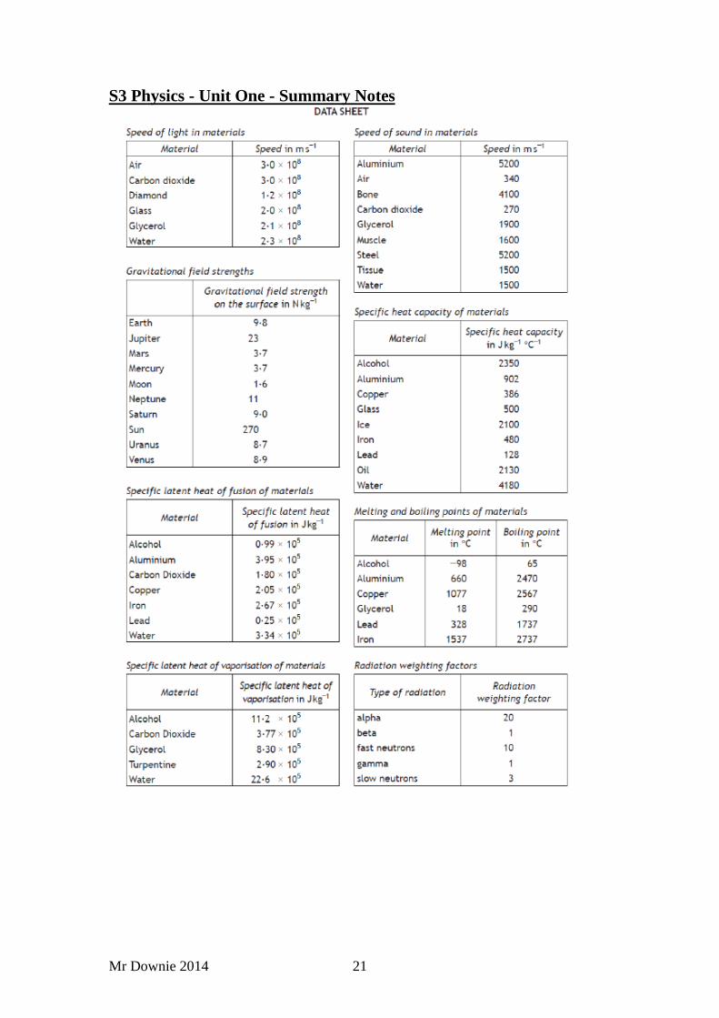
S3 Physics - Unit One - Summary Notes
Mr Downie 2014 3
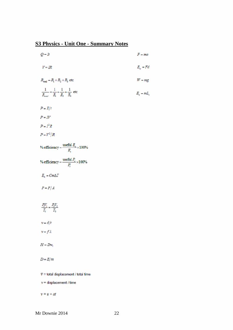
S3 Physics - Unit One - Summary Notes
Current Electric current is due to the flow of electrons.
Electrons are negative charges which are found in an atom.
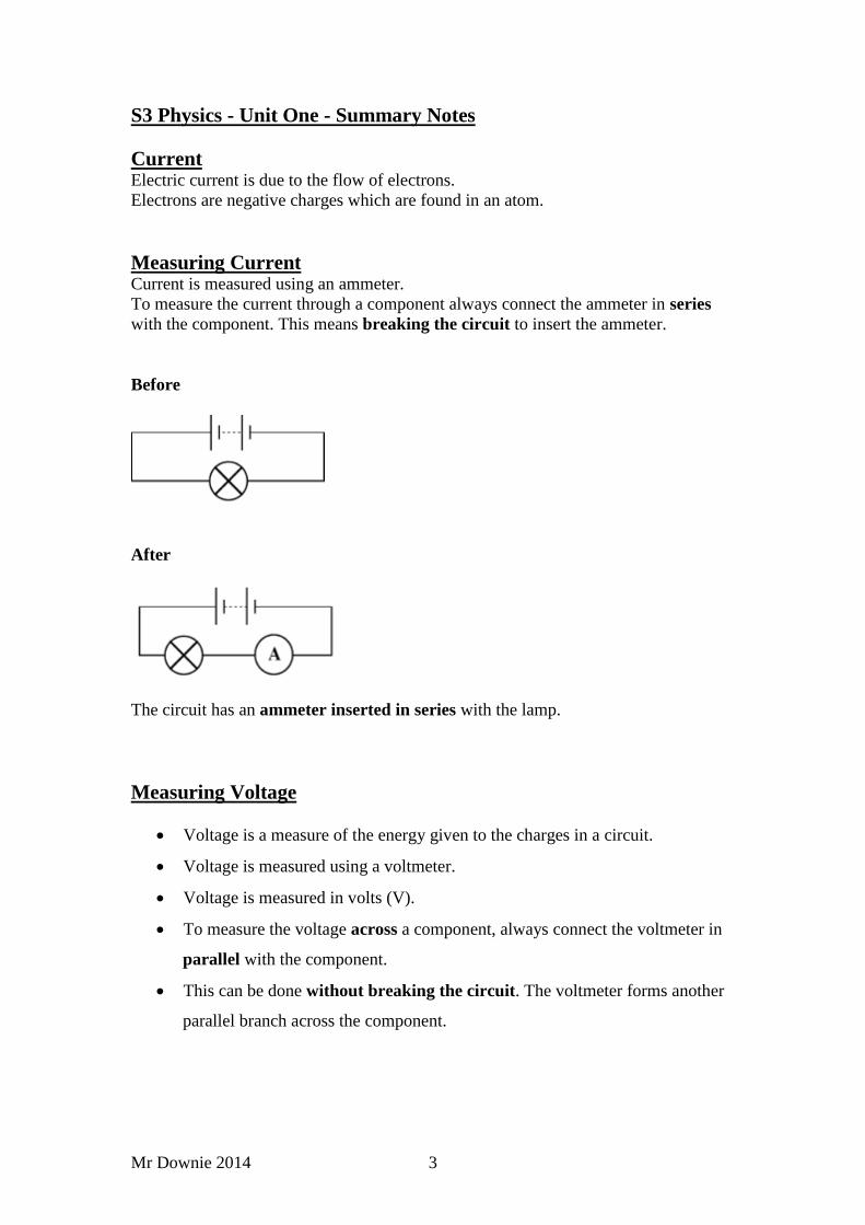
Measuring Current Current is measured using an ammeter.
To measure the current through a component always connect the ammeter in series
with the component. This means breaking the circuit to insert the ammeter.
Before
After
The circuit has an ammeter inserted in series with the lamp.
Measuring Voltage
Voltage is a measure of the energy given to the charges in a circuit.
Voltage is measured using a voltmeter.
Voltage is measured in volts (V).
To measure the voltage across a component, always connect the voltmeter in
parallel with the component.
This can be done without breaking the circuit. The voltmeter forms another
parallel branch across the component.
Mr Downie 2014 4
S3 Physics - Unit One - Summary Notes
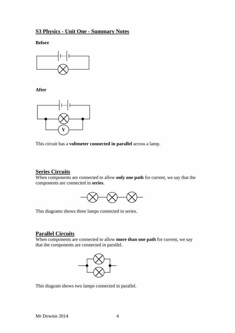
Before
After
This circuit has a voltmeter connected in parallel across a lamp.
Series Circuits When components are connected to allow only one path for current, we say that the
components are connected in series.
This diagrams shows three lamps connected in series.
Parallel Circuits When components are connected to allow more than one path for current, we say
that the components are connected in parallel.
This diagram shows two lamps connected in parallel.
Mr Downie 2014 5
S3 Physics - Unit One - Summary Notes
Mr Downie 2014 6
S3 Physics - Unit One - Summary Notes
Resistance Materials oppose the flow of current and some materials oppose the flow by more
than others. The opposition to the flow of current is called resistance. An increase in
resistance will cause a decrease in the current.
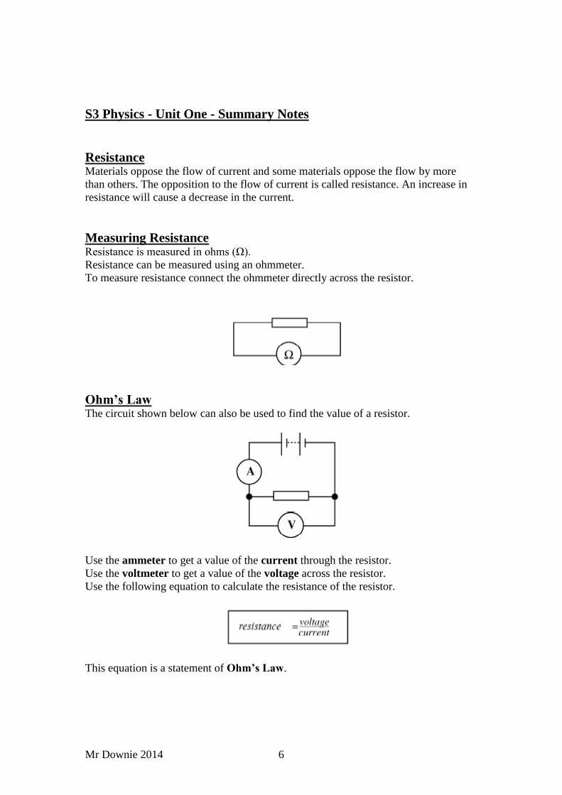
Measuring Resistance Resistance is measured in ohms (Ω).
Resistance can be measured using an ohmmeter.
To measure resistance connect the ohmmeter directly across the resistor.
Ohm’s Law The circuit shown below can also be used to find the value of a resistor.
Use the ammeter to get a value of the current through the resistor.
Use the voltmeter to get a value of the voltage across the resistor.
Use the following equation to calculate the resistance of the resistor.
This equation is a statement of Ohm’s Law.

Mr Downie 2014 7
S3 Physics - Unit One - Summary Notes
Ohm’s Law
Ohm’s Law can also be written using symbols as:-
V = I x R
Where,
Voltage is represented by the symbol – V
Current is represented by the symbol – I
Resistance is represented by the symbol – R
Example One
The current through a resistor is 0.1amperes when the voltage across it is 12volts.
Calculate the resistance.
Current = 0.1amperes
Voltage = 12volts
Resistance =?
Example Two What is the value of the voltage across a 6Ω resistor when a current of 2amperes is
flowing through the resistor?
R = 6Ω I = 2A V =?
V = I x R
V = 2 x 6
V = 12V
Example Three A 24V battery is connected to an 8Ω resistor. What is the value of the current that
flows through the resistor?
V = 24V R = 8Ω I =?
V = I x R
24 = I x 8
I = 24 / 8
I = 3A
Mr Downie 2014 8
S3 Physics - Unit One - Summary Notes
Electronics Every electronic system can be divided into three parts – input, process and output.
The input part detects a type of energy and then changes it into electrical energy.
The process part is used to process the electrical energy.
The output part changes the electrical energy into a useful type of energy.
Electronic systems are often shown as block diagrams.
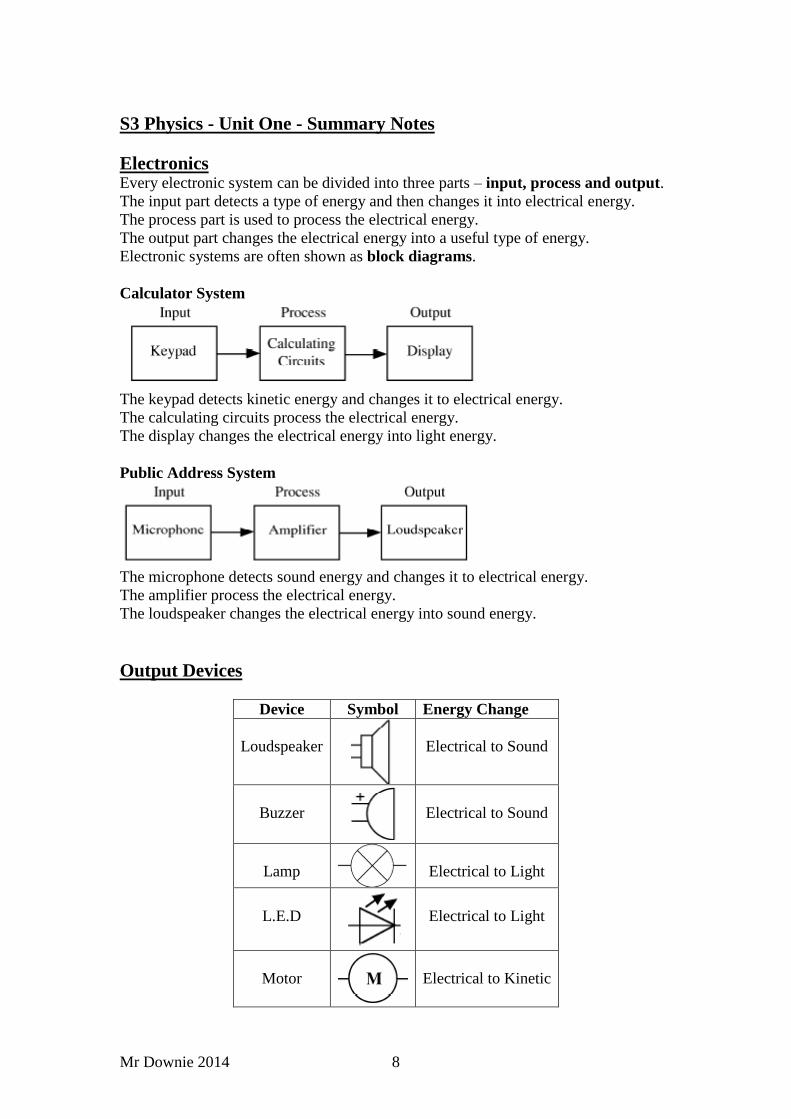
Calculator System
The keypad detects kinetic energy and changes it to electrical energy.
The calculating circuits process the electrical energy.
The display changes the electrical energy into light energy.
Public Address System
The microphone detects sound energy and changes it to electrical energy.
The amplifier process the electrical energy.
The loudspeaker changes the electrical energy into sound energy.
Output Devices
Device Symbol Energy Change
Loudspeaker
Electrical to Sound
Buzzer
Electrical to Sound
Lamp
Electrical to Light
L.E.D
Electrical to Light
Motor
Electrical to Kinetic
Mr Downie 2014 9
S3 Physics - Unit One - Summary Notes
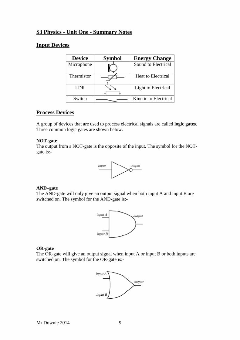
Input Devices
Device Symbol Energy Change Microphone
Sound to Electrical
Thermistor
Heat to Electrical
LDR
Light to Electrical
Switch Kinetic to Electrical
Process Devices
A group of devices that are used to process electrical signals are called logic gates.
Three common logic gates are shown below.
NOT-gate
The output from a NOT-gate is the opposite of the input. The symbol for the NOT-
gate is:-
AND–gate
The AND-gate will only give an output signal when both input A and input B are
switched on. The symbol for the AND-gate is:-
OR-gate
The OR-gate will give an output signal when input A or input B or both inputs are
switched on. The symbol for the OR-gate is:-
Mr Downie 2014 10
S3 Physics - Unit One - Summary Notes
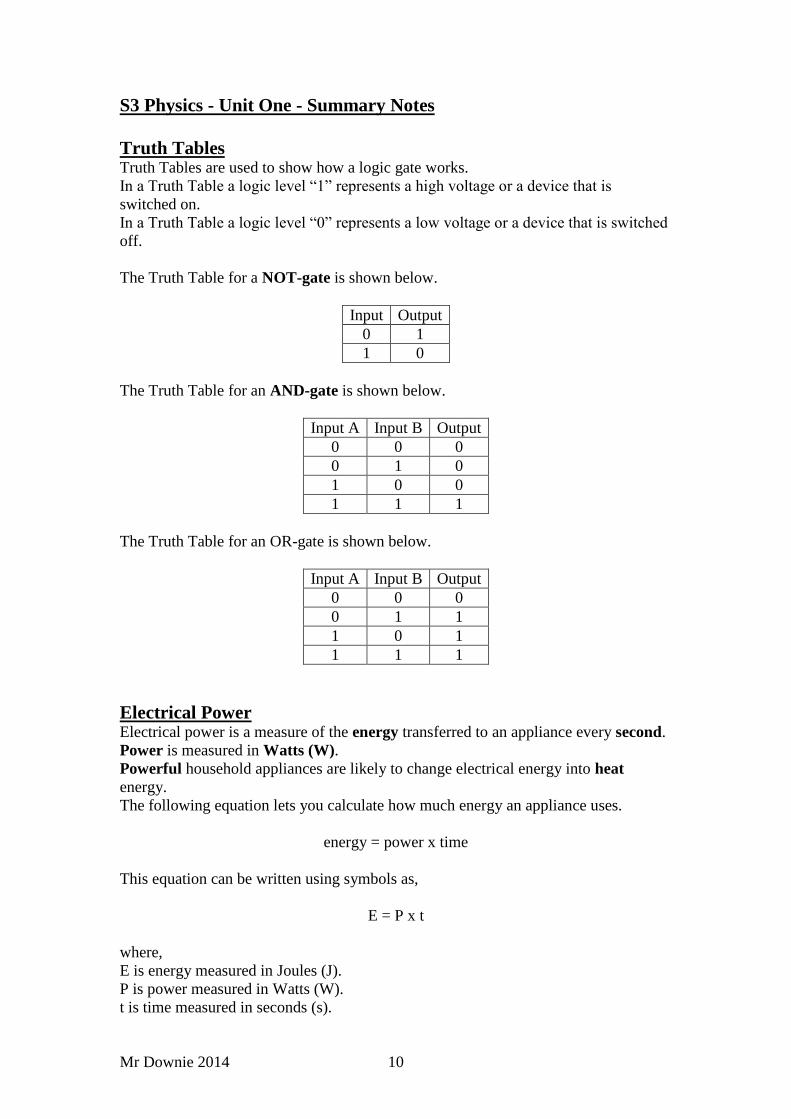
Truth Tables Truth Tables are used to show how a logic gate works.
In a Truth Table a logic level “1” represents a high voltage or a device that is
switched on.
In a Truth Table a logic level “0” represents a low voltage or a device that is switched
off.
The Truth Table for a NOT-gate is shown below.
Input Output
0 1
1 0
The Truth Table for an AND-gate is shown below.
Input A Input B Output
0 0 0
0 1 0
1 0 0
1 1 1
The Truth Table for an OR-gate is shown below.
Input A Input B Output
0 0 0
0 1 1
1 0 1
1 1 1
Electrical Power Electrical power is a measure of the energy transferred to an appliance every second.
Power is measured in Watts (W).
Powerful household appliances are likely to change electrical energy into heat
energy.
The following equation lets you calculate how much energy an appliance uses.
energy = power x time
This equation can be written using symbols as,
E = P x t
where,
E is energy measured in Joules (J).
P is power measured in Watts (W).
t is time measured in seconds (s).
Mr Downie 2014 11
S3 Physics - Unit One - Summary Notes
This equation shows that electrical energy costs will increase when,
the time of use increases
the power of the appliance increases
To save energy and money, always switch off appliances after use.
Example One
How much energy is used by a 3kW kettle that is switched on for five minutes?
P = 3kW = 3000W t = 5minutes = 5 x 60 = 300s E =?
E = P x t
E = 3000 x 300
E = 900,000J
Example Two
How much energy is used by a 5W computer screen which is switched on for 4hours?
P = 5W t = 4hours = 4 x 60 x 60 = 14,400s E =?
E = P x t
E = 5 x 14400
E = 72,000J
Electrical Power and Current When an appliance has a high power rating, the greater the value of current that flows
in the appliance.
For household appliances the current that flows to them is controlled by a fuse in the
plug. The symbol for a fuse is shown below.
In the UK the two most common values of fuse are 3amperes (3A) and 13amperes
(13A).
As a general rule if the power rating is 700W or more, a 13A fuse must be used. If the
power rating is less than 700W, a 3A fuse must be used.
Some other important information on the rating plates of household appliances is:-
the value of the mains voltage, which is 230V for the UK.
the double insulation symbol (shown below), which indicates that the
appliance does not need an Earth wire.

Mr Downie 2014 12
S3 Physics - Unit One - Summary Notes
Efficiency
There are main occasions when we want to change energy from one type into another,
for example electrical energy to light energy in a lamp. Unfortunately, appliances
often produce unwanted types of energy, like heat in a light bulb or sound from an
electric motor.
Efficiency is a measure of how much useful energy (or power) an appliance can
produce. Efficiency is usually quoted as a percentage and can be calculated using the
following equation.
Example
When the total energy input to a microwave is 4000J the useful energy output is
2400J. What is the efficiency of the microwave?
Electromagnetism
A permanent magnet (e.g. a fridge magnet) has a permanent magnet field around it.
We cannot see the magnetic field but we can see how it affects objects, e.g.
iron based objects are attracted to the permanent magnet
a compass needle will change direction in the magnetic field around a
permanent magnet
The magnetic field around a permanent magnet can be drawn by using magnetic field
lines. This is shown below.
All permanent magnets have a fixed North-pole (N in the diagram) and a fixed South-
pole (S in the diagram).
The arrows on the field lines always point towards the South-pole.
When the field lines are close together this means the magnetic field is strong.
Mr Downie 2014 13
S3 Physics - Unit One - Summary Notes
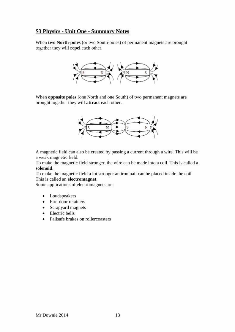
When two North-poles (or two South-poles) of permanent magnets are brought
together they will repel each other.
When opposite poles (one North and one South) of two permanent magnets are
brought together they will attract each other.
A magnetic field can also be created by passing a current through a wire. This will be
a weak magnetic field.
To make the magnetic field stronger, the wire can be made into a coil. This is called a
solenoid.
To make the magnetic field a lot stronger an iron nail can be placed inside the coil.
This is called an electromagnet.
Some applications of electromagnets are:
Loudspeakers
Fire-door retainers
Scrapyard magnets
Electric bells
Failsafe brakes on rollercoasters
Mr Downie 2014 14
S3 Physics - Unit One - Summary Notes
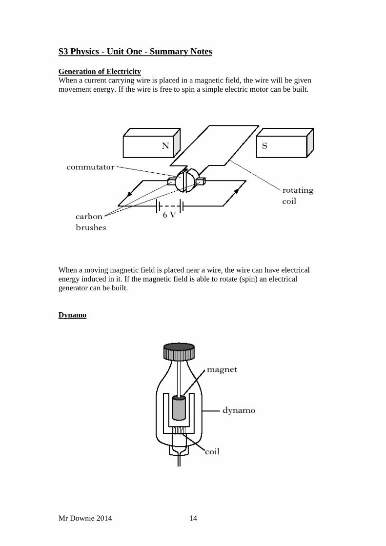
Generation of Electricity
When a current carrying wire is placed in a magnetic field, the wire will be given
movement energy. If the wire is free to spin a simple electric motor can be built.
When a moving magnetic field is placed near a wire, the wire can have electrical
energy induced in it. If the magnetic field is able to rotate (spin) an electrical
generator can be built.
Dynamo
Mr Downie 2014 15
S3 Physics - Unit One - Summary Notes
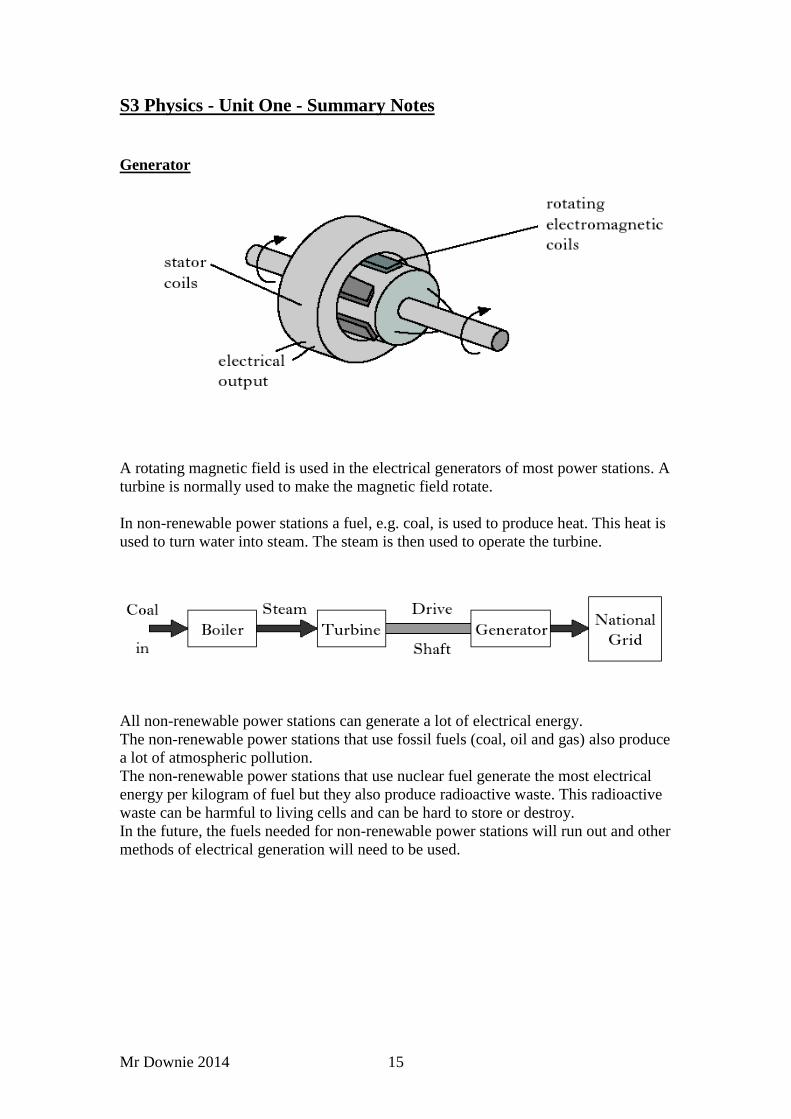
Generator
A rotating magnetic field is used in the electrical generators of most power stations. A
turbine is normally used to make the magnetic field rotate.
In non-renewable power stations a fuel, e.g. coal, is used to produce heat. This heat is
used to turn water into steam. The steam is then used to operate the turbine.
All non-renewable power stations can generate a lot of electrical energy.
The non-renewable power stations that use fossil fuels (coal, oil and gas) also produce
a lot of atmospheric pollution.
The non-renewable power stations that use nuclear fuel generate the most electrical
energy per kilogram of fuel but they also produce radioactive waste. This radioactive
waste can be harmful to living cells and can be hard to store or destroy.
In the future, the fuels needed for non-renewable power stations will run out and other
methods of electrical generation will need to be used.
Mr Downie 2014 16
S3 Physics - Unit One - Summary Notes
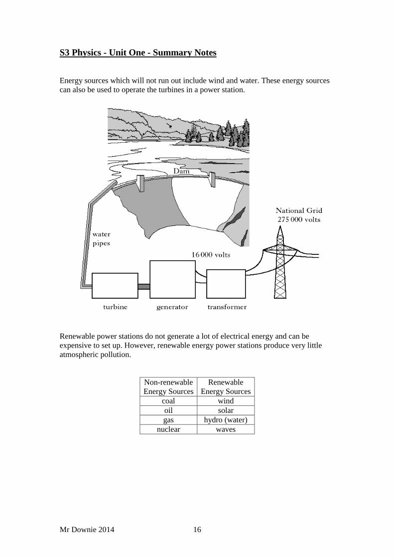
Energy sources which will not run out include wind and water. These energy sources
can also be used to operate the turbines in a power station.
Renewable power stations do not generate a lot of electrical energy and can be
expensive to set up. However, renewable energy power stations produce very little
atmospheric pollution.
Non-renewable
Energy Sources
Renewable
Energy Sources
coal wind
oil solar
gas hydro (water)
nuclear waves
Mr Downie 2014 17
S3 Physics - Unit One - Summary Notes
You might also be able to carry out calculations to find the value of current using the
following equation.
where,
I = electric current measured in amperes, A.
Q = electric charge measured in coulombs, C.
t = time measured in seconds, s.
Example
Calculate the electric current in a circuit if 3C of charge pass appoint in a time of one
minute.
I = ? Q =3C t = one minute = 60s
I = Q / t
I = 3 / 60
I = 0.05A
You might also be able to find current and voltage values by applying series and
parallel circuit rules.
Examples
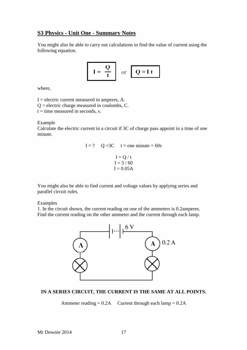
1. In the circuit shown, the current reading on one of the ammeters is 0.2amperes.
Find the current reading on the other ammeter and the current through each lamp.
IN A SERIES CIRCUIT, THE CURRENT IS THE SAME AT ALL POINTS.
Ammeter reading = 0.2A Current through each lamp = 0.2A
Mr Downie 2014 18
S3 Physics - Unit One - Summary Notes
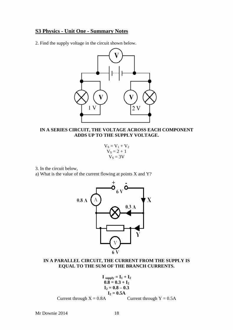
2. Find the supply voltage in the circuit shown below.
IN A SERIES CIRCUIT, THE VOLTAGE ACROSS EACH COMPONENT
ADDS UP TO THE SUPPLY VOLTAGE.
VS = V1 + V2
VS = 2 + 1
VS = 3V
3. In the circuit below,
a) What is the value of the current flowing at points X and Y?
IN A PARALLEL CIRCUIT, THE CURRENT FROM THE SUPPLY IS
EQUAL TO THE SUM OF THE BRANCH CURRENTS.
I supply = I1 + I2
0.8 = 0.3 + I2
I2 = 0.8 – 0.3
I2 = 0.5A
Current through X = 0.8A Current through Y = 0.5A

Mr Downie 2014 19
S3 Physics - Unit One - Summary Notes
b) What is the voltage across the lamp?
IN A PARALLEL CIRCUIT THE VOLTAGE ACROSS THE SUPPLY IS
EQUAL TO THE VOLTAGE ACROSS EVERY BRANCH.
If the supply voltage is 0.6V, then the voltage across the lamp must be 0.6V
POWER CALCULATIONS
You might also be able to calculate the value of a fuse for an appliance by using the
following equation.
Power =Current x Voltage
This equation can also be written using symbols: -
P = I x V
where,
P is the power measured in Watts
I is the current measured in Amperes
V is the voltage measured in Volts
Example
If the mains voltage is 230V, should a 3A or a 13A fuse be used in an 1840W hair-
dryer?
P = 1840W I = ? V = 230V
P = I x V
1840 = I x 230
I = 1840 / 230
I = 8A
As 8A is greater than 3A you should use a 13A fuse.
Mr Downie 2014 20
S3 Physics - Unit One - Summary Notes
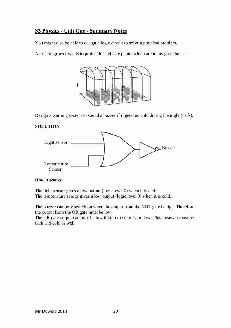
You might also be able to design a logic circuit to solve a practical problem.
A tomato grower wants to protect his delicate plants which are in his greenhouse.
Design a warning system to sound a buzzer if it gets too cold during the night (dark).
SOLUTION
Light sensor
Buzzer
Temperature
Sensor
How it works
The light sensor gives a low output (logic level 0) when it is dark.
The temperature sensor gives a low output (logic level 0) when it is cold.
The buzzer can only switch on when the output from the NOT gate is high. Therefore
the output from the OR gate must be low.
The OR gate output can only be low if both the inputs are low. This means it must be
dark and cold as well.
Mr Downie 2014 21
S3 Physics - Unit One - Summary Notes
Mr Downie 2014 22
S3 Physics - Unit One - Summary Notes
Mr Downie 2014 23
S3 Physics - Unit One - Summary Notes


![National 5 Dynamics and Space Summary Notes€¦ · National 5 – Dynamics and Space – Summary Notes [Type here] Mr Downie 2019 Average Speed (Revision from Level 4 and N4) To](https://img.pdfslide.us/doc/110x75/5e8dd88db57a2261bd651fa6/national-5-dynamics-and-space-summary-notes-national-5-a-dynamics-and-space-a.jpg)