Embed Size (px)
Citation preview
Reduction of elements to be assembled that lead to following benefits:- Reduction of assembly cost- Risk reduction of assembly operation mistakes- More safety in severe working conditions- Easier maintenence and replacement operations
Definitely improved resistance against oil leakage Risk elimination of unscrewing troubles in the field Design solution available for most common Q-Safe series
MQS-DHI PRODUCT RANGE
& ™
FIELD APPLICATIONS
KEY FEATURES AND BENEFITS
Construction & earth moving
Forestry Agriculture
mm inch dash MPa PSI L/min. PSI MPa PSI N lb. cc. cubic inch. MPa PSI MPa PSI MPa PSI 10 3/8” -06 25 3625 23 6,1 0,08 11,6 130 289 0,007 0,0004 140 20300 110 15950 140 20300 Not allowed
12,5 1/2” -08 25 3625 45 11,9 0,05 7,3 140 311 0,008 0,0005 100 14500 120 17400 150 21750 Not allowed
SIZE WORKINGPRESSURE(Dynamic)
RATED FLOW
PRESSURE DROP
by rated fl owCONNECTION
EFFORTOIL SPILLAGEConnection/
Disconnection
MINIMUM BURST PRESSURE (MPa)
CONNECTION /DISCONNECTION UNDER PRESSURE
NMPa
Male Female M+F
mm inch dash MPa PSI L/min. PSI MPa PSI N lb. cc. cubic inch. MPa PSI MPa PSI MPa PSI 12,5 1/2” -08 30 4350 45 11,9 0,09 13,1 80 178 1,8 0,110 125 18125 160 23200 160 23200 Not allowed
SIZE WORKINGPRESSURE(Dynamic)
RATED FLOW
PRESSURE DROP
by rated fl owCONNECTION
EFFORTOIL SPILLAGEConnection/
Disconnection
MINIMUM BURST PRESSURE (MPa)
CONNECTION /DISCONNECTION UNDER PRESSURE
NMPa
Male Female M+F
63
90
49MQS-DHI
Quick coupling > fi tting
Quick coupling > adaptor > fi tting
SIZE PART NUMBER TAIL DIMENSIONS mm
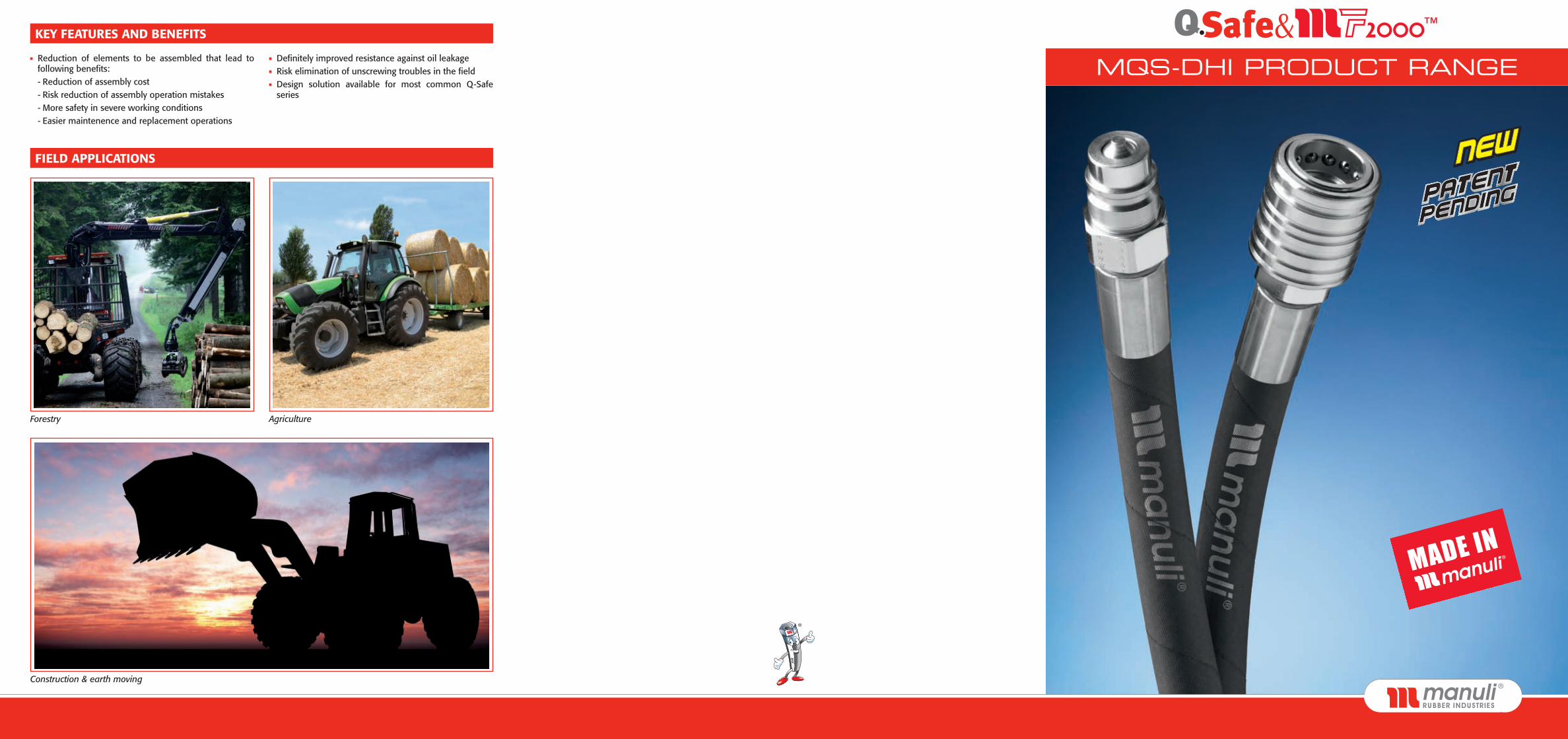
mm inch dash Female Coupling Male Coupling A B C D E F
10 3/8” -06Q34111MF1A-06-06 Q33911MF1A-06-06 3/8” MF2000 69,7 58,3 A+B-15,9 ø32 ch. 27 ch. 27Q34111MF1A-06-08 Q33911MF1A-06-08 1/2” MF2000 69,7 56,7 A+B-15,9 ø32 ch. 27 ch. 27
12,5 1/2” -08Q34111MF1A-08-08 Q33911MF1A-08-08 1/2” MF2000 78,8 66,7 A+B-17,1 ø38 ch. 34 ch. 34Q34111MF1A-08-12 Q33911MF1A-08-12 3/4” MF2000 75,7 65,1 A+B-17,1 ø38 ch. 34 ch. 34
SIZE PART NUMBER TAIL DIMENSIONS mm
mm inch dash Male Coupling A B
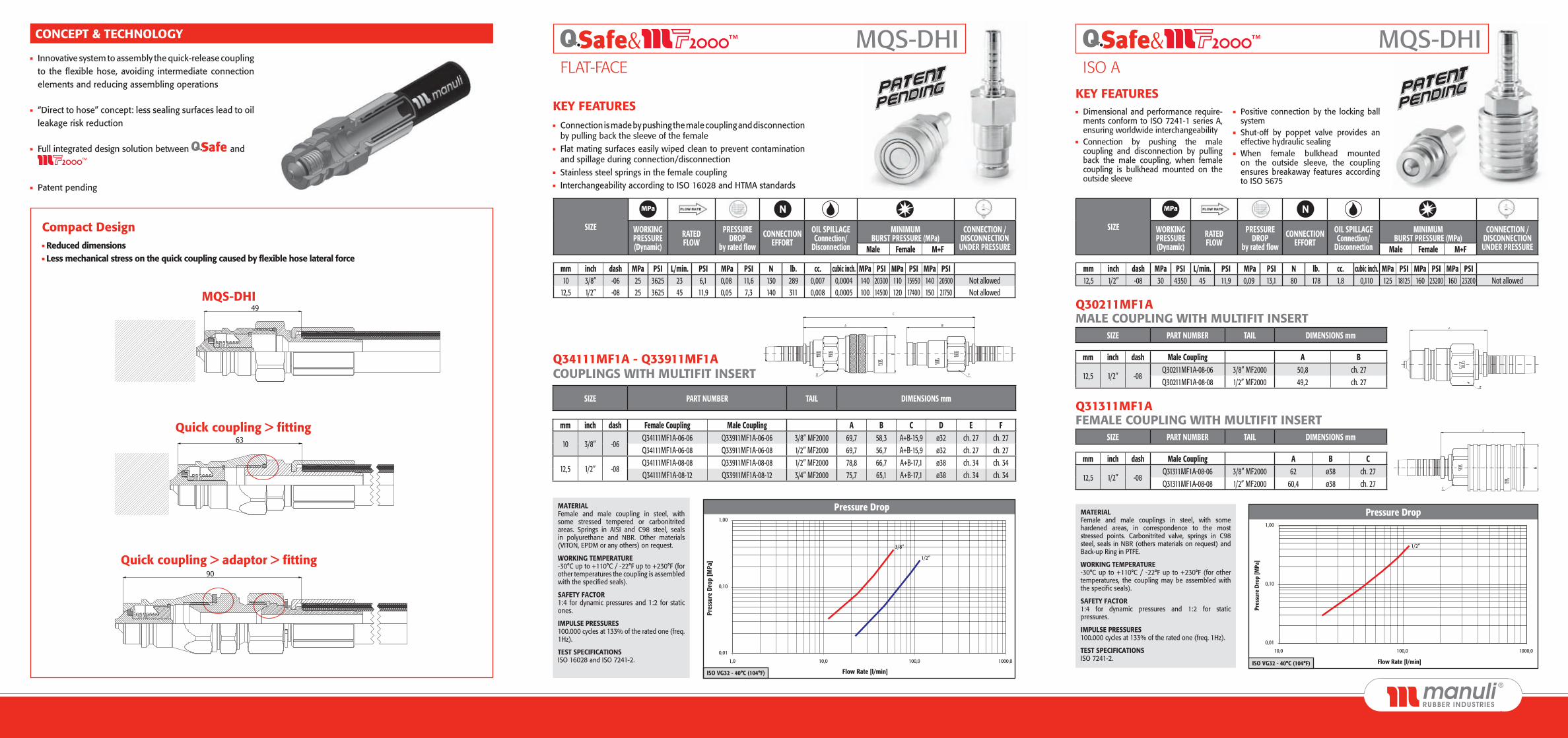
12,5 1/2” -08Q30211MF1A-08-06 3/8” MF2000 50,8 ch. 27Q30211MF1A-08-08 1/2” MF2000 49,2 ch. 27
SIZE PART NUMBER TAIL DIMENSIONS mm
mm inch dash Male Coupling A B C
12,5 1/2” -08Q31311MF1A-08-06 3/8” MF2000 62 ø38 ch. 27Q31311MF1A-08-08 1/2” MF2000 60,4 ø38 ch. 27
Innovative system to assembly the quick-release coupling to the flexible hose, avoiding intermediate connection elements and reducing assembling operations
“Direct to hose” concept: less sealing surfaces lead to oil leakage risk reduction
Full integrated design solution between and ™
Patent pending
Pressure Drop
0,01
0,10
1,00
1,0 10,0 100,0
3/8”
1/2”
1000,0
Flow Rate [l/min]ISO VG32 - 40°C (104°F)
Pres
sure
Dro
p [M
Pa]
Pressure Drop
0,01
0,10
1,00
10,0 100,0 1000,0
Pres
sure
Dro
p [M
Pa]
Flow Rate [l/min]
1/2”
ISO VG32 - 40°C (104°F)
Compact Design Reduced dimensions Less mechanical stress on the quick coupling caused by flexible hose lateral force
CONCEPT & TECHNOLOGY & ™ MQS-DHIFLAT-FACE
& ™ MQS-DHIISO A
Q34111MF1A - Q33911MF1A COUPLINGS WITH MULTIFIT INSERT
Q31311MF1A FEMALE COUPLING WITH MULTIFIT INSERT
Q30211MF1A MALE COUPLING WITH MULTIFIT INSERT
MATERIAL Female and male coupling in steel, with some stressed tempered or carbonitrited areas. Springs in AISI and C98 steel, seals in polyurethane and NBR. Other materials (VITON, EPDM or any others) on request.
WORKING TEMPERATURE -30°C up to +110°C / -22°F up to +230°F (for other temperatures the coupling is assembled with the specified seals).
SAFETY FACTOR 1:4 for dynamic pressures and 1:2 for static ones.
IMPULSE PRESSURES 100.000 cycles at 133% of the rated one (freq. 1Hz).
TEST SPECIFICATIONS ISO 16028 and ISO 7241-2.
KEY FEATURES Connection is made by pushing the male coupling and disconnection
by pulling back the sleeve of the female Flat mating surfaces easily wiped clean to prevent contamination
and spillage during connection/disconnection Stainless steel springs in the female coupling Interchangeability according to ISO 16028 and HTMA standards
KEY FEATURES Dimensional and performance require-
ments conform to ISO 7241-1 series A, ensuring worldwide interchangeability
Connection by pushing the male coupling and disconnection by pulling back the male coupling, when female coupling is bulkhead mounted on the outside sleeve
Positive connection by the locking ball system
Shut-off by poppet valve provides an effective hydraulic sealing
When female bulkhead mounted on the outside sleeve, the coupling ensures breakaway features according to ISO 5675
MATERIAL Female and male couplings in steel, with some hardened areas, in correspondence to the most stressed points. Carbonitrited valve, springs in C98 steel, seals in NBR (others materials on request) and Back-up Ring in PTFE.
WORKING TEMPERATURE -30°C up to +110°C / -22°F up to +230°F (for other temperatures, the coupling may be assembled with the specific seals).
SAFETY FACTOR 1:4 for dynamic pressures and 1:2 for static pressures.
IMPULSE PRESSURES 100.000 cycles at 133% of the rated one (freq. 1Hz).
TEST SPECIFICATIONS ISO 7241-2.


![INDEX [] · iso 5675 push pull coupling ( with bulkhead) push pull agri series 71 8 iso 5675 breakaway coupling breakaway series 73 iso 5675 breakaway coupling (with male end ) breakaway](https://img.pdfslide.us/doc/110x75/5c168d0809d3f29f108cc8b6/index-iso-5675-push-pull-coupling-with-bulkhead-push-pull-agri-series.jpg)