Embed Size (px)
Citation preview
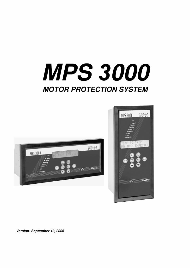
MPS 3000
MOTOR PROTECTION SYSTEM
Version: September 12, 2006
CHANGES FROM MPC2000 TO MPS3000
Page 2 of 67
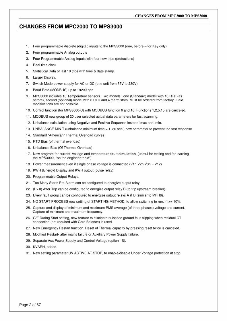
CHANGES FROM MPC2000 TO MPS3000
1. Four programmable discrete (digital) inputs to the MPS3000 (one, before – for Key only).
2. Four programmable Analog outputs
3. Four Programmable Analog Inputs with four new trips (protections)
4. Real time clock.
5. Statistical Data of last 10 trips with time & date stamp.
6. Larger Display.
7. Switch Mode power supply for AC or DC (one unit from 85V to 230V)
8. Baud Rate (MODBUS) up to 19200 bps.
9. MPS3000 includes 10 Temperature sensors. Two models: one (Standard) model with 10 RTD (as before), second (optional) model with 6 RTD and 4 thermistors. Must be ordered from factory. Field modifications are not possible.
10. Control function (for MPS3000-C) with MODBUS function 6 and 16. Functions 1,2,5,15 are canceled.
11. MODBUS new group of 20 user selected actual data parameters for fast scanning.
12. Unbalance calculation using Negative and Positive Sequence instead Imax and Imin.
13. UNBALANCE MIN T (unbalance minimum time = 1..30 sec.) new parameter to prevent too fast response.
14. Standard “American” Thermal Overload curves
15. RTD Bias (of thermal overload)
16. Unbalance Bias (Of Thermal Overload)
17. New program for current, voltage and temperature fault simulation. (useful for testing and for learning the MPS3000, "on the engineer table")
18. Power measurement even if single phase voltage is connected (V1n,V2n,V3n = V12)
19. KWH (Energy) Display and KWH output (pulse relay)
20. Programmable Output Relays.
21. Too Many Starts Pre Alarm can be configured to energize output relay.
22. (I > 0) After Trip can be configured to energize output relay B (to trip upstream breaker).
23. Every fault group can be configured to energize output relays A & B (similar to MPR6).
24. NO START PROCESS new setting of STARTING METHOD, to allow switching to run, if I>= 10%.
25. Capture and display of minimum and maximum RMS average (of three phases) voltage and current. Capture of minimum and maximum frequency.
26. G/F During Start setting, new feature to eliminate nuisance ground fault tripping when residual CT connection (not required with Core Balance) is used.
27. New Emergency Restart function. Reset of Thermal capacity by pressing reset twice is canceled.
28. Modified Restart- after mains failure or Auxiliary Power Supply failure.
29. Separate Aux Power Supply and Control Voltage (option –S).
30. KVARH, added.
31. New setting parameter UV ACTIVE AT STOP, to enable/disable Under Voltage protection at stop.
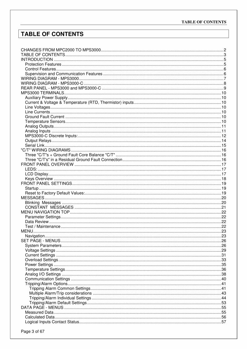
TABLE OF CONTENTS
Page 3 of 67
TABLE OF CONTENTS CHANGES FROM MPC2000 TO MPS3000...........................................................................................................2 TABLE OF CONTENTS..........................................................................................................................................3 INTRODUCTION ....................................................................................................................................................5
Protection Features .............................................................................................................................................5 Control Features..................................................................................................................................................6 Supervision and Communication Features .........................................................................................................6
WIRING DIAGRAM - MPS3000..............................................................................................................................7 WIRING DIAGRAM - MPS3000-C..........................................................................................................................8 REAR PANEL - MPS3000 and MPS3000-C ..........................................................................................................9 MPS3000 TERMINALS.........................................................................................................................................10
Auxiliary Power Supply......................................................................................................................................10 Current & Voltage & Temperature (RTD, Thermistor) inputs............................................................................10 Line Voltages.....................................................................................................................................................10 Line Currents .....................................................................................................................................................10 Ground Fault Current ........................................................................................................................................10 Temperature Sensors........................................................................................................................................10 Analog Outputs..................................................................................................................................................11 Analog Inputs ....................................................................................................................................................11 MPS3000-C Discrete Inputs:.............................................................................................................................12 Output Relays....................................................................................................................................................14 Serial Link..........................................................................................................................................................15
"C/T" WIRING DIAGRAMS ...................................................................................................................................16 Three "C/T"s + Ground Fault Core Balance "C/T" ............................................................................................16 Three "C/T's" in a Residual Ground Fault Connection......................................................................................16
FRONT PANEL OVERVIEW ................................................................................................................................17 LEDS: ................................................................................................................................................................17 LCD Display.......................................................................................................................................................17 Keys Overview ..................................................................................................................................................18
FRONT PANEL SETTINGS..................................................................................................................................19 Startup ...............................................................................................................................................................19 Reset to Factory Default Values:.......................................................................................................................19
MESSAGES..........................................................................................................................................................20 Blinking Messages ...........................................................................................................................................20 CONSTANT MESSAGES ................................................................................................................................21
MENU NAVIGATION TOP....................................................................................................................................22 Parameter Settings............................................................................................................................................22 Data Review ......................................................................................................................................................22 Test / Maintenance............................................................................................................................................22
MENU....................................................................................................................................................................23 Navigation..........................................................................................................................................................23
SET PAGE - MENUS............................................................................................................................................26 System Parameters...........................................................................................................................................26 Voltage Settings ................................................................................................................................................29 Current Settings ................................................................................................................................................31 Overload Settings..............................................................................................................................................33 Power Settings ..................................................................................................................................................35 Temperature Settings........................................................................................................................................36 Analog I/O Settings ...........................................................................................................................................38 Communication Settings ...................................................................................................................................40 Tripping/Alarm Options......................................................................................................................................41
Tripping Alarm Common Settings..................................................................................................................41 Multiple Alarm/Trip considerations ................................................................................................................43 Tripping/Alarm Individual Settings .................................................................................................................44 Tripping/Alarm Default Settings.....................................................................................................................53
DATA PAGE - MENUS .........................................................................................................................................55 Measured Data..................................................................................................................................................55 Calculated Data.................................................................................................................................................56 Logical Inputs Contact Status............................................................................................................................57
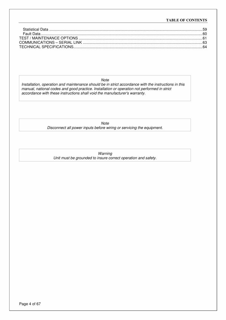
TABLE OF CONTENTS
Page 4 of 67
Statistical Data ..................................................................................................................................................59 Fault Data ..........................................................................................................................................................60
TEST / MAINTENANCE OPTIONS ......................................................................................................................61 COMMUNICATIONS – SERIAL LINK ..................................................................................................................63 TECHNICAL SPECIFICATIONS...........................................................................................................................64
Note
Installation, operation and maintenance should be in strict accordance with the instructions in this manual, national codes and good practice. Installation or operation not performed in strict accordance with these instructions shall void the manufacturer's warranty.
Note
Disconnect all power inputs before wiring or servicing the equipment.
Warning
Unit must be grounded to insure correct operation and safety.
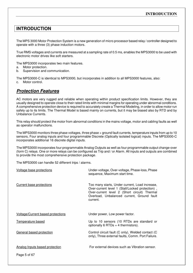
INTRODUCTION
Page 5 of 67
INTRODUCTION The MPS 3000 Motor Protection System is a new generation of micro processor based relay / controller designed to operate with a three (3) phase induction motors. True RMS voltages and currents are measured at a sampling rate of 0.5 ms, enables the MPS3000 to be used with electronic motor drives like soft starters. The MPS3000 incorporates two main features. a. Motor protection. b. Supervision and communication. The MPS3000-C is identical to MPS3000, but incorporates in addition to all MPS3000 features, also: c. Motor control.
Protection Features AC motors are very rugged and reliable when operating within product specification limits. However, they are usually designed to operate close to their rated limits with minimal margins for operating under abnormal conditions. A comprehensive protection device is required to accurately create a Thermal Modeling, in order to allow motor run safely up to its limits. The Thermal Model is based mainly on currents, but it may be biased also by RTD and by Unbalance Currents. This relay should protect the motor from abnormal conditions in the mains voltage, motor and cabling faults as well as operator malfunctions. The MPS3000 monitors three phase voltages, three phase + ground fault currents, temperature inputs from up to 10 sensors, Four analog inputs and four programmable Discrete (Optically isolated logical) inputs. The MPS3000-C incorporates additional 16 discrete digital inputs. The MPS3000 incorporates four programmable Analog Outputs as well as four programmable output change-over (form C) relays. One or more relays can be configured as Trip and / or Alarm. All inputs and outputs are combined to provide the most comprehensive protection package. The MPS3000 can handle 52 different trips / alarms. Voltage base protections Under-voltage, Over-voltage, Phase-loss, Phase
sequence, Maximum start time.
Current base protections Too many starts, Under current, Load increase, Over-current level 1 (Stall/Locked protection) , Over-current level 2 (Short circuit) Thermal Overload, Unbalanced current, Ground fault current.
Voltage/Current based protections Under power, Low power factor.
Temperature based Up to 10 sensors (10 RTDs are standard or optionally 6 RTDs + 4 thermistors).
General based protection Control circuit fault (C only), Welded contact (C only), Three external faults, Comm. Port Failure.
Analog Inputs based protection For external devices such as Vibration sensor.
INTRODUCTION
Page 6 of 67
Two levels for most faults Usually used for Alarm and Trip. Protection levels and time delay settings are individually configured using the key pad on the front panel or through communication. Unique Tripping / Alarm options make it possible to program any fault as an Alarm, Trip, both or none. This unique facility also enables controlled fault Reset possibilities. Authorized key, extends the reset possibilities. A unique calculated "Time to Trip" feature allows the operator or host computer to take corrective actions before tripping.
Control Features The MPS3000-C has the same functionality as the MPS3000 and also incorporates also control capabilities. It can control various starting methods like Direct Online, Star Delta, Soft Starters, Reversing and Two Speeds. Twenty optically isolated logic inputs are used to enable many types of control: Local, remote (for PLC without serial link) or through RS485 serial link. Two or three relays may be used to control DOL (direct online), Star/Delta, Soft-starters, Two Speed and Reversing -starting. Throughout the entire document MPS3000–C information is written over a gray background. Please ignore this information for the MPS3000.
Supervision and Communication Features A Liquid Crystal Display (LCD), together with a keypad and LEDs enables user friendly interface, accurate digital parameters setting, actual parameters readings, and detailed trip and alarm message displays. Unauthorized setting changes can easily be prevented by the correct use of the Authorized key input terminals. Measured data Phase and line voltages, Phase currents, Ground fault current, Power, Reactive
Power, Power factor, RTD temperatures (thermistor resistances) and Analog Inputs. Calculated data Motor load in % of FLC, Equivalent motor current, Unbalance current, Thermal
Capacity, Time to trip, Time to start. Logic inputs status Individual status of all input contacts. Statistical data Motors running hours, Total number of starts, Total number of trips, Last start time,
last start peak current, Total Energy, minimum and maximum values of voltage, current and frequency.
Fault data Last Trip, Last Alarm, Phase currents at time of trip, Ground fault current at time of trip, Phase voltages at time of trip, last 10 faults with time and date stamp.
Fault Simulation – Special Test / Maintenance page allows simulation (only during first 10 hours from auxiliary supply power up) by setting voltages currents and temperature “actual” values. The Simulation mode can be used for periodic testing of the relay. It can be used also for getting familiar with the MPS3000 modes of operation and features.
RS485 serial link (with MODBUS RTU communication protocol), operating at baud rate of 1200 to 38400 bps enables monitoring of both the "set page" and actual parameters. Changes of the "set page" parameters through the serial link make it very easy to enter user’s set points in place of the factory default parameters. The serial link enables remote control of both the MPS3000 and the motor. RS485 enables 32 MPS3000 units to be connected on the same link to the host computer. When a need for more than 32 units arises, using MMI & Data highway equipment non limited number of MPS3000's can be connected to a host computer.
WIRING DIAGRAM - MPS3000
Page 7 of 67
WIRING DIAGRAM - MPS3000
WIRING DIAGRAM - MPS3000-C
Page 8 of 67
WIRING DIAGRAM - MPS3000-C
REAR PANEL - MPS3000 and MPS3000-C
Page 9 of 67
REAR PANEL - MPS3000 and MPS3000-C
MPS3000 TERMINALS
Page 10 of 67
MPS3000 TERMINALS
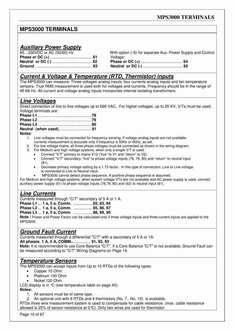
Auxiliary Power Supply 85…230VDC or AC (50/60) Hz With option (-S) for separate Aux. Power Supply and Control Phase or DC (+) ...................................... 61 Voltage: Neutral or DC (-) .................................... 62 Phase or DC (+) ...................................... 64 Ground .................................................... 63 Neutral or DC (-) .................................... 65
Current & Voltage & Temperature (RTD, Thermistor) inputs The MPS3000 can measure: Three voltages analog inputs, four currents analog inputs and ten temperature sensors. True RMS measurement is used both for voltages and currents. Frequency should be in the range of 45-66 Hz. All current and voltage analog inputs incorporate internal isolating transformers.
Line Voltages Direct connection of line to line voltages up to 690 VAC. For higher voltages, up to 25 KV, V/Ts must be used. Voltage terminals are: Phase L1 .................................................78 Phase L2 .................................................79 Phase L3 .................................................80 Neutral (when used)….......................... 81 Notes:
1. Line voltages must be connected for frequency sensing. If voltage analog inputs are not available, currents measurement is accurate only if frequency is 50Hz or 60Hz, as set.
2. For low voltage mains, all three phase voltages must be connected as shown in the wiring diagram. 3. For Medium and high voltage systems, when only a single V/T is used:
• Connect "V/T" primary to mains V12 (“live” to V1 and “return” to V2).
• Connect "V/T" secondary: “live” to phase voltage inputs (78, 79, 80) and “return” to neutral input (81).
• Decrease primary voltage setting by a 1.73 factor. In this type of connection, Line to Line voltage is connected to Line to Neutral input.
• MPS3000 cannot detect phase sequence. A positive phase sequence is assumed. For Medium and high voltage systems, when system voltage VTs are not available and AC power supply is used, connect auxiliary power supply (61) to phase voltage inputs (78,79, 80) and (62) to neutral input (81).
Line Currents Currents measured through "C/T" secondary of 5 A or 1 A. Phase L1 ... 1 a, 5 a, Comm. ................. 82, 83, 84 Phase L2 ... 1 a, 5 a, Comm. ................. 85, 86, 87 Phase L3 ... 1 a, 5 a, Comm. ................. 88, 89, 90 Note : Power and Power Factor can be calculated only if three voltage inputs and three current inputs are applied to the
MPS3000.
Ground Fault Current Currents measured through a differential "C/T" with a secondary of 5 A or 1A. All phases..1 A, 5 A, COMM.................. 91, 92, 93 Note: It is recommended to use Core Balance "C/T". If a Core Balance "C/T" is not available, Ground Fault can be measured according to "C/T" Wiring Diagrams on Page 14.
Temperature Sensors The MPS3000 can accept inputs from Up to 10 RTDs of the following types:
• Copper 10 Ohm
• Platinum 100 Ohm
• Nickel 120 Ohm LCD display is in °C (see temperature table on page 40). Notes:
1. All sensors must be of same type. 2. An optional unit with 6 RTDs and 4 thermistors (No. 7...No. 10) is available.
RTDs three wire measurement system is used to compensate for cable resistance. (max. cable resistance allowed is 25% of sensor resistance at 0°C). Only two wires are used for thermistor.
MPS3000 TERMINALS
Page 11 of 67
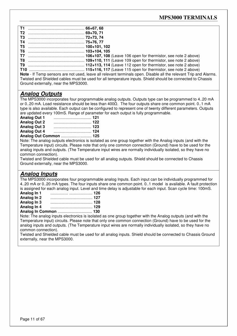
T1 ................................................... 66+67, 68 T2 ................................................... 69+70, 71 T3 ................................................... 72+73, 74 T4 ................................................... 75+76, 77 T5 ................................................... 100+101, 102 T6 ................................................... 103+104, 105 T7 ................................................... 106+107, 108 (Leave 106 open for thermistor, see note 2 above) T8 ................................................... 109+110, 111 (Leave 109 open for thermistor, see note 2 above) T9 ................................................... 112+113, 114 (Leave 112 open for thermistor, see note 2 above) T10 .................................................. 115+116, 117 (Leave 115 open for thermistor, see note 2 above) Note - If Temp sensors are not used, leave all relevant terminals open. Disable all the relevant Trip and Alarms. Twisted and Shielded cables must be used for all temperature inputs. Shield should be connected to Chassis Ground externally, near the MPS3000.
Analog Outputs The MPS3000 incorporates four programmable analog outputs. Outputs type can be programmed to 4..20 mA or 0..20 mA. Load resistance should be less than 400Ω. The four outputs share one common point. 0..1 mA type is also available. Each output can be configured to represent one of twenty different parameters. Outputs are updated every 100mS. Range of parameter for each output is fully programmable. Analog Out 1 .................................. 121 Analog Out 2 .................................. 122 Analog Out 3 .................................. 123 Analog Out 4 .................................. 124 Analog Out Common ..............….......... 125 Note: The analog outputs electronics is isolated as one group together with the Analog inputs (and with the Temperature input) circuits. Please note that only one common connection (Ground) have to be used for the analog inputs and outputs. (The Temperature input wires are normally individually isolated, so they have no common connection). Twisted and Shielded cable must be used for all analog outputs. Shield should be connected to Chassis Ground externally, near the MPS3000.
Analog Inputs The MPS3000 incorporates four programmable analog Inputs. Each input can be individually programmed for 4..20 mA or 0..20 mA types. The four inputs share one common point. 0..1 model is available. A fault protection is assigned for each analog input. Level and time delay is adjustable for each input. Scan cycle time: 100mS. Analog In 1 ................ ..................... 126 Analog In 2 ...................................... 127 Analog In 3 ...................................... 128 Analog In 4 ...................................... 129 Analog In Common ............................... 130 Note: The analog inputs electronics is isolated as one group together with the Analog outputs (and with the Temperature input) circuits. Please note that only one common connection (Ground) have to be used for the analog inputs and outputs. (The Temperature input wires are normally individually isolated, so they have no common connection). Twisted and Shielded cable must be used for all analog inputs. Shield should be connected to Chassis Ground externally, near the MPS3000.
MPS3000 TERMINALS
Page 12 of 67
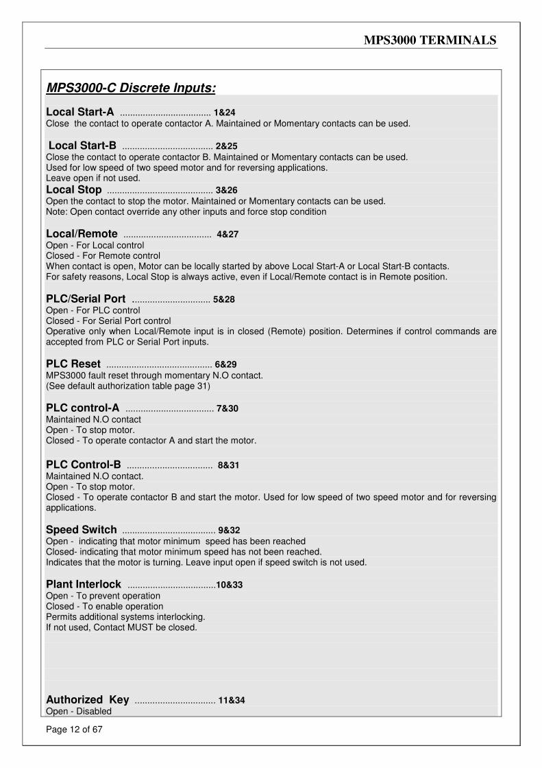
MPS3000-C Discrete Inputs:
Local Start-A .................................... 1&24
Close the contact to operate contactor A. Maintained or Momentary contacts can be used.
Local Start-B .................................... 2&25
Close the contact to operate contactor B. Maintained or Momentary contacts can be used. Used for low speed of two speed motor and for reversing applications. Leave open if not used.
Local Stop .......................................... 3&26
Open the contact to stop the motor. Maintained or Momentary contacts can be used. Note: Open contact override any other inputs and force stop condition
Local/Remote ................................... 4&27
Open - For Local control Closed - For Remote control When contact is open, Motor can be locally started by above Local Start-A or Local Start-B contacts. For safety reasons, Local Stop is always active, even if Local/Remote contact is in Remote position.
PLC/Serial Port ............................... 5&28
Open - For PLC control Closed - For Serial Port control Operative only when Local/Remote input is in closed (Remote) position. Determines if control commands are accepted from PLC or Serial Port inputs.
PLC Reset .......................................... 6&29
MPS3000 fault reset through momentary N.O contact. (See default authorization table page 31)
PLC control-A ................................... 7&30
Maintained N.O contact Open - To stop motor. Closed - To operate contactor A and start the motor.
PLC Control-B .................................. 8&31
Maintained N.O contact. Open - To stop motor. Closed - To operate contactor B and start the motor. Used for low speed of two speed motor and for reversing applications.
Speed Switch ..................................... 9&32
Open - indicating that motor minimum speed has been reached Closed- indicating that motor minimum speed has not been reached. Indicates that the motor is turning. Leave input open if speed switch is not used.
Plant Interlock ...................................10&33
Open - To prevent operation Closed - To enable operation Permits additional systems interlocking. If not used, Contact MUST be closed.
Authorized Key ................................ 11&34
Open - Disabled
MPS3000 TERMINALS
Page 13 of 67
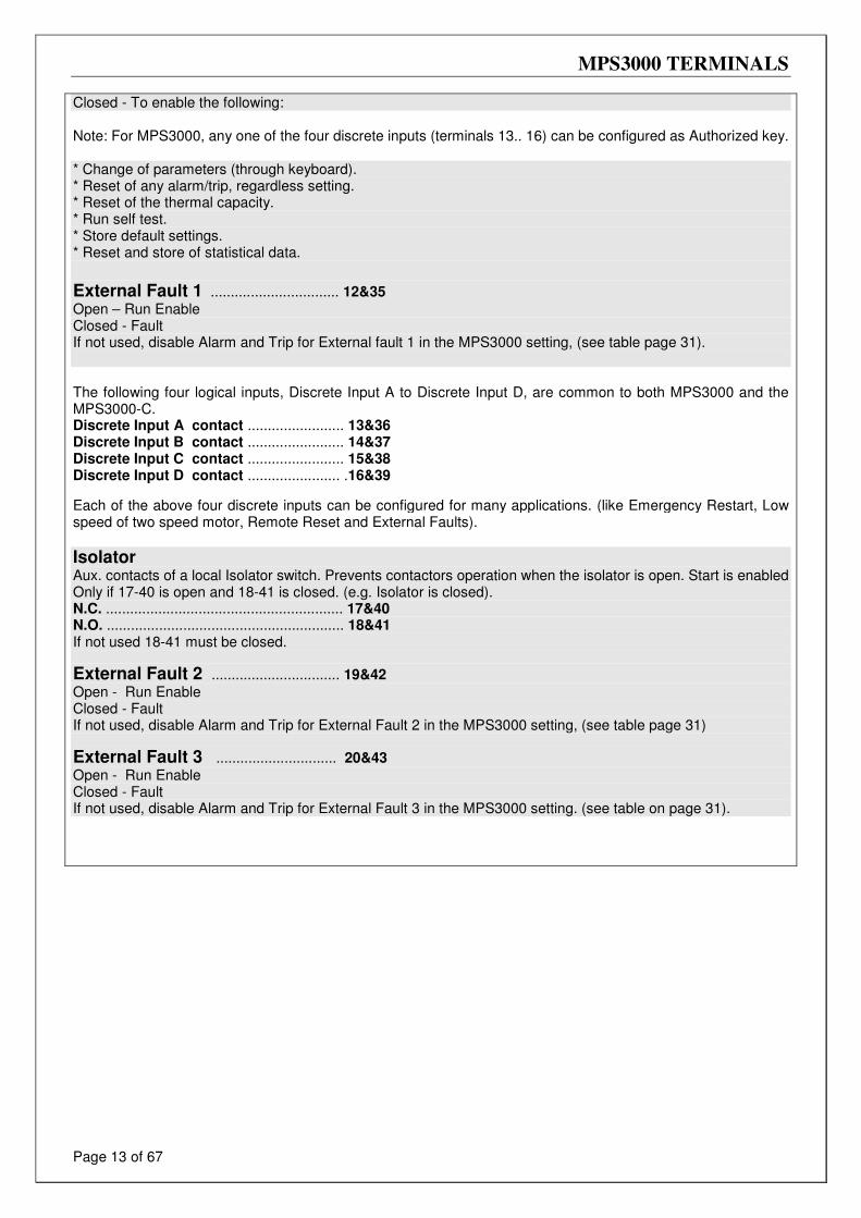
Closed - To enable the following: Note: For MPS3000, any one of the four discrete inputs (terminals 13.. 16) can be configured as Authorized key. * Change of parameters (through keyboard). * Reset of any alarm/trip, regardless setting. * Reset of the thermal capacity. * Run self test. * Store default settings. * Reset and store of statistical data.
External Fault 1 ................................ 12&35
Open – Run Enable Closed - Fault If not used, disable Alarm and Trip for External fault 1 in the MPS3000 setting, (see table page 31). The following four logical inputs, Discrete Input A to Discrete Input D, are common to both MPS3000 and the MPS3000-C. Discrete Input A contact ........................ 13&36 Discrete Input B contact ........................ 14&37 Discrete Input C contact ........................ 15&38 Discrete Input D contact ....................... .16&39
Each of the above four discrete inputs can be configured for many applications. (like Emergency Restart, Low speed of two speed motor, Remote Reset and External Faults).
Isolator Aux. contacts of a local Isolator switch. Prevents contactors operation when the isolator is open. Start is enabled Only if 17-40 is open and 18-41 is closed. (e.g. Isolator is closed). N.C. ........................................................... 17&40 N.O. ........................................................... 18&41 If not used 18-41 must be closed.
External Fault 2 ................................ 19&42
Open - Run Enable Closed - Fault If not used, disable Alarm and Trip for External Fault 2 in the MPS3000 setting, (see table page 31)
External Fault 3 .............................. 20&43
Open - Run Enable Closed - Fault If not used, disable Alarm and Trip for External Fault 3 in the MPS3000 setting. (see table on page 31).
MPS3000 TERMINALS
Page 14 of 67
Output Relays The MPS3000 incorporates four output relays. Each has a C/O contact, rated 8 A / 250 VAC resistive, 2000 VA inductive. The four relays can be configured for alarm, alarm fail-safe, trip, trip fail-safe, overload, earth (Ground) Fault, KWH pulses and also for external contactors control required for the MPS3000-C. Note: When a relay is configured as an alarm Fail-Safe or trip Fail-Safe, the relay is immediately energized when the auxiliary power supply is connected to terminals 61 & 62. The following N.O and N.C. terminals are given for Non-Energized relays.
Output Relay A: N.C .......................................................... 44&45 N.O .......................................................... 44&46 Relay A can be configured as an Alarm, Alarm Fail-Safe, Tripping / Alarm (where it can be set for any group of faults), # Of Starts Pre Alarm (can be used to prevent start which will cause Too Many Starts fault) , U/V start prevent or KWH pulse relay. See later for additional control functions used with the MPS3000-C. Output Relay B: N.C .......................................................... 47&48 N.O .......................................................... 47&49
Relay B can be configured as Trip, Trip Fail-Safe, Tripping / Alarm (where it can be set for any group of faults) or # Of Starts Pre Alarm, u/v Start Prevent or (I > 0) After Trip relay. See later for additional control functions used with the MPS3000-C. When configured as (I > 0) After Trip, it can be used to trip upstream breaker if current still flows After the MPS3000 has issued a Trip signal.
Output Relay C: N.C .......................................................... 50&51 N.O ...........................................................50&52 Relay C can be configured as Alarm Fail-Safe, Alarm, Contactor A/B status, Start/Run and Running indication. See later for additional control functions used with the MPS3000-C.
Output Relay D: N.C .......................................................... 53&54 N.O ...........................................................53&55
Relay D can be configured as a Trip, Trip Fail Safe or Ready relay. The relays can be configured to receive two isolated alarm signals and two isolated trip signals.
Note: When a relay is configured for Fail Safe operation, relay is energized when MPS3000 is powered and de-energized upon fault. Relay C is designed mainly to be used as an alarm fail-safe, to alarm constantly when the unit is not powered.
MPS3000 TERMINALS
Page 15 of 67
MPS3000-C special use: The relays can be configured with contactors control functions which may be required, according to the control application. Output A Relay: Can be configured as one of: * DOL starting * Star period of Star-Delta starting * Forward of a forward-reverse motor * High speed of two-speed motor Output B Relay: Can be configured (by parameter setting) as one of the following functions: * Delta period of Star/Delta starting * Reverse of a forward-reverse motor * Low speed of two-speed motor Output C Relay: Can be configured (by parameter setting) as one of the following functions: * Contactor A status. * Contactor B status. * Start/Run - controls line contactor in Star-Delta starters.
Serial Link Standard RS485 Half Duplex, with MODBUS protocol. Twisted shielded pair should be used for wiring. Shield should be connected to Chassis Ground externally,
near the MPS3000. Acceptable baud rates: 1200, 2400, 4800, 9600 and 19200 BPS. Serial Port (+) .........................................23 Serial Port (-) ......................................... 22 Serial Port (shield) ................................. 63 Notes:
1. Auxiliary Power Supply must power-cycled after changing communication's settings (e.g. baud-rate).
2. Connect 120 Ohm resistors between (+) and (-) at the end and at the beginning of the line.
"C/T" WIRING DIAGRAMS
Page 16 of 67
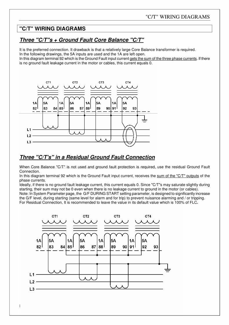
"C/T" WIRING DIAGRAMS
Three "C/T"s + Ground Fault Core Balance "C/T" It is the preferred connection. It drawback is that a relatively large Core Balance transformer is required. In the following drawings, the 5A inputs are used and the 1A are left open. In this diagram terminal 92 which is the Ground Fault input current gets the sum of the three phase currents. If there is no ground fault leakage current in the motor or cables, this current equals 0.
Three "C/T's" in a Residual Ground Fault Connection When Core Balance "C/T" is not used and ground fault protection is required, use the residual Ground Fault Connection. In this diagram terminal 92 which is the Ground Fault input current, receives the sum of the "C/T" outputs of the phase currents. Ideally, if there is no ground fault leakage current, this current equals 0. Since "C/T"s may saturate slightly during starting, their sum may not be 0 even when there is no leakage current to ground in the motor (or cables). Note: In System Parameter page, the G/F DURING START setting parameter, is designed to significantly increase the G/F level, during starting (same level for alarm and for trip) to prevent nuisance alarming and / or tripping. For Residual Connection, It is recommended to leave the value in its default value which is 100% of FLC.
FRONT PANEL OVERVIEW
Page 17 of 67
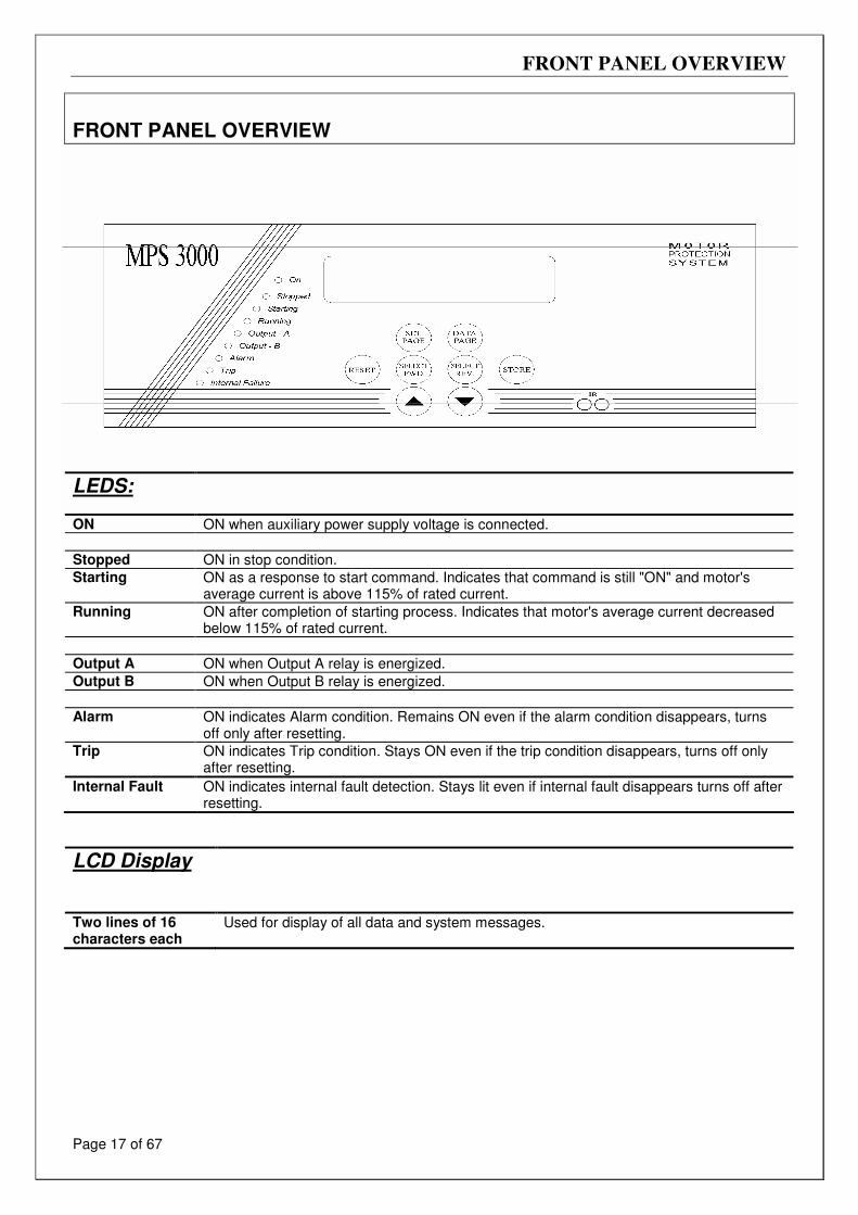
FRONT PANEL OVERVIEW
LCD Display
Two lines of 16 characters each
Used for display of all data and system messages.
LEDS:
ON ON when auxiliary power supply voltage is connected.
Stopped ON in stop condition.
Starting ON as a response to start command. Indicates that command is still "ON" and motor's average current is above 115% of rated current.
Running ON after completion of starting process. Indicates that motor's average current decreased below 115% of rated current.
Output A ON when Output A relay is energized.
Output B ON when Output B relay is energized.
Alarm ON indicates Alarm condition. Remains ON even if the alarm condition disappears, turns off only after resetting.
Trip ON indicates Trip condition. Stays ON even if the trip condition disappears, turns off only after resetting.
Internal Fault ON indicates internal fault detection. Stays lit even if internal fault disappears turns off after resetting.
FRONT PANEL OVERVIEW
Page 18 of 67
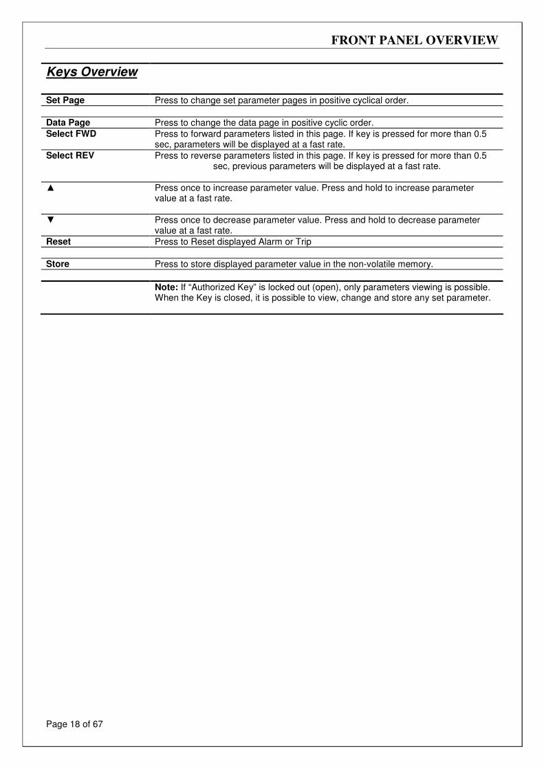
Keys Overview
Set Page Press to change set parameter pages in positive cyclical order.
Data Page Press to change the data page in positive cyclic order.
Select FWD Press to forward parameters listed in this page. If key is pressed for more than 0.5 sec, parameters will be displayed at a fast rate.
Select REV Press to reverse parameters listed in this page. If key is pressed for more than 0.5 sec, previous parameters will be displayed at a fast rate.
Press once to increase parameter value. Press and hold to increase parameter value at a fast rate.
Press once to decrease parameter value. Press and hold to decrease parameter value at a fast rate.
Reset Press to Reset displayed Alarm or Trip
Store Press to store displayed parameter value in the non-volatile memory.
Note: If “Authorized Key” is locked out (open), only parameters viewing is possible. When the Key is closed, it is possible to view, change and store any set parameter.
FRONT PANEL OVERVIEW
Page 19 of 67
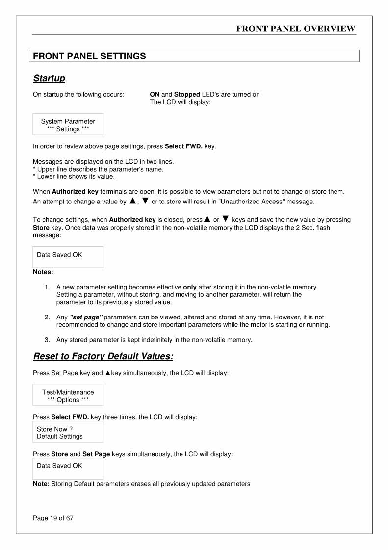
FRONT PANEL SETTINGS
Startup On startup the following occurs: ON and Stopped LED's are turned on The LCD will display:
System Parameter
*** Settings ***
In order to review above page settings, press Select FWD. key. Messages are displayed on the LCD in two lines. * Upper line describes the parameter's name. * Lower line shows its value. When Authorized key terminals are open, it is possible to view parameters but not to change or store them.
An attempt to change a value by , or to store will result in "Unauthorized Access" message.
To change settings, when Authorized key is closed, press or keys and save the new value by pressing
Store key. Once data was properly stored in the non-volatile memory the LCD displays the 2 Sec. flash message:
Data Saved OK
Notes:
1. A new parameter setting becomes effective only after storing it in the non-volatile memory. Setting a parameter, without storing, and moving to another parameter, will return the parameter to its previously stored value.
2. Any "set page" parameters can be viewed, altered and stored at any time. However, it is not
recommended to change and store important parameters while the motor is starting or running.
3. Any stored parameter is kept indefinitely in the non-volatile memory.
Reset to Factory Default Values: Press Set Page key and key simultaneously, the LCD will display:
Test/Maintenance
*** Options ***
Press Select FWD. key three times, the LCD will display:
Store Now ? Default Settings
Press Store and Set Page keys simultaneously, the LCD will display:
Data Saved OK
Note: Storing Default parameters erases all previously updated parameters
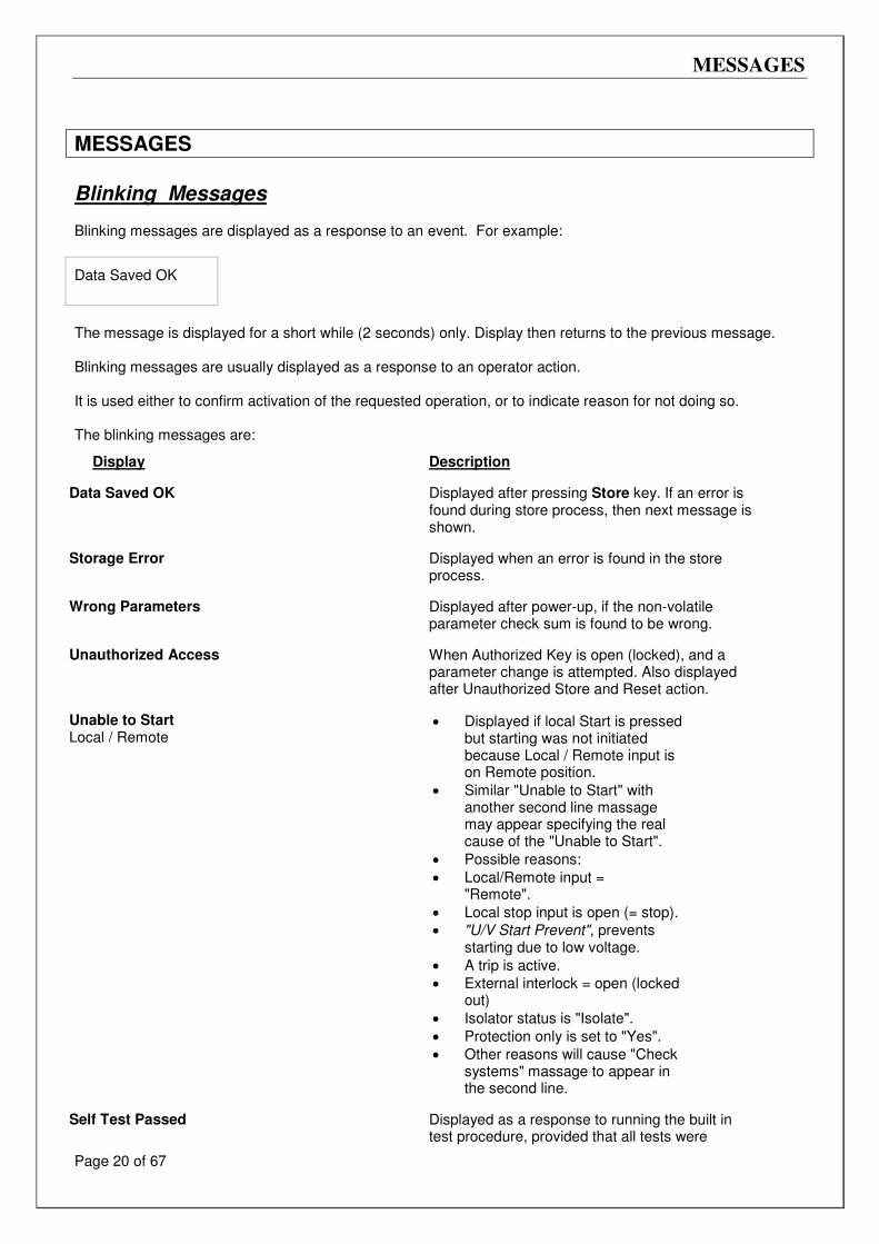
MESSAGES
Page 20 of 67
MESSAGES
Blinking Messages Blinking messages are displayed as a response to an event. For example:
The message is displayed for a short while (2 seconds) only. Display then returns to the previous message. Blinking messages are usually displayed as a response to an operator action. It is used either to confirm activation of the requested operation, or to indicate reason for not doing so. The blinking messages are:
Display
Description
Data Saved OK
Displayed after pressing Store key. If an error is found during store process, then next message is shown.
Storage Error
Displayed when an error is found in the store process.
Wrong Parameters
Displayed after power-up, if the non-volatile parameter check sum is found to be wrong.
Unauthorized Access
When Authorized Key is open (locked), and a parameter change is attempted. Also displayed after Unauthorized Store and Reset action.
Unable to Start Local / Remote
• Displayed if local Start is pressed
but starting was not initiated because Local / Remote input is on Remote position.
• Similar "Unable to Start" with another second line massage may appear specifying the real cause of the "Unable to Start".
• Possible reasons:
• Local/Remote input = "Remote".
• Local stop input is open (= stop).
• "U/V Start Prevent", prevents starting due to low voltage.
• A trip is active.
• External interlock = open (locked out)
• Isolator status is "Isolate".
• Protection only is set to "Yes".
• Other reasons will cause "Check systems" massage to appear in the second line.
Self Test Passed
Displayed as a response to running the built in test procedure, provided that all tests were
Data Saved OK
MESSAGES
Page 21 of 67
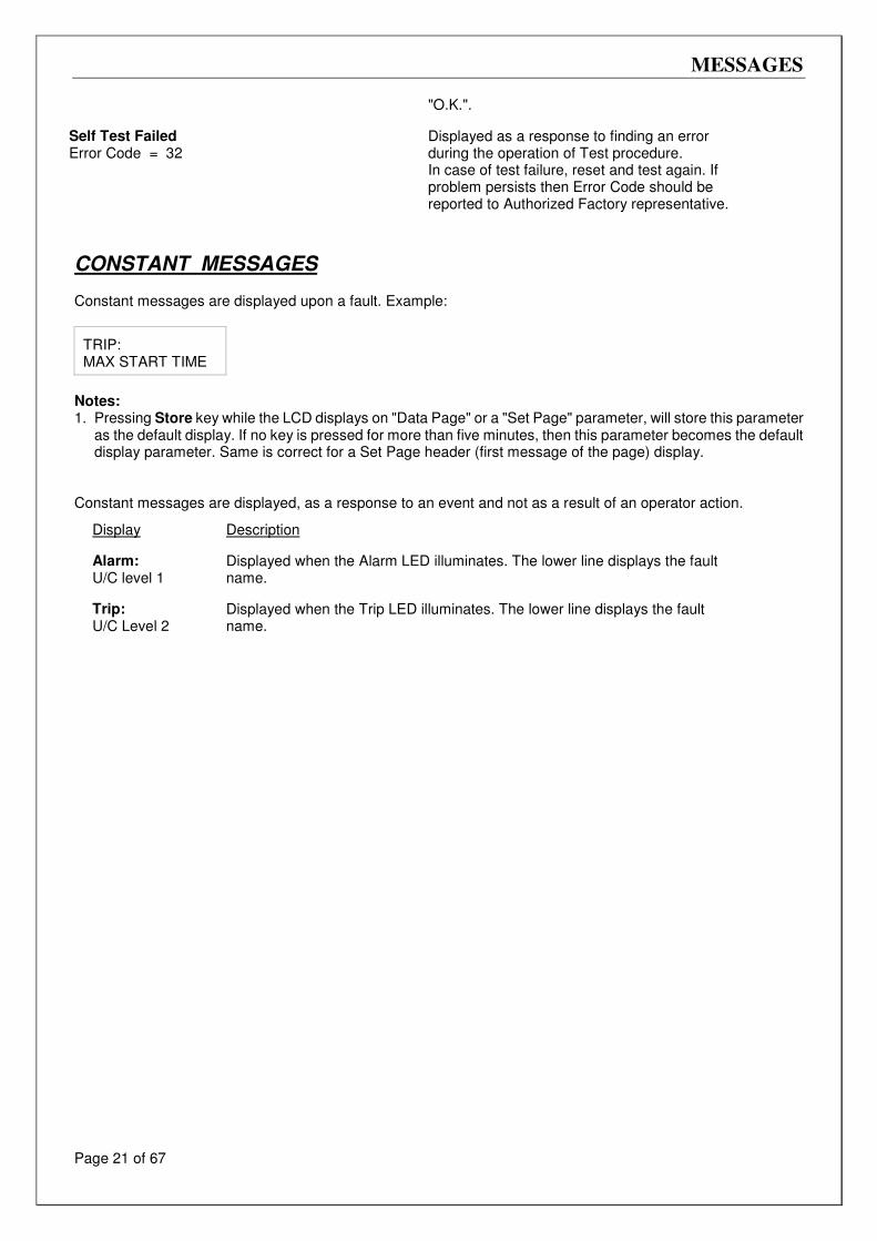
"O.K.". Self Test Failed Error Code = 32
Displayed as a response to finding an error during the operation of Test procedure. In case of test failure, reset and test again. If problem persists then Error Code should be reported to Authorized Factory representative.
CONSTANT MESSAGES Constant messages are displayed upon a fault. Example:
TRIP: MAX START TIME
Notes: 1. Pressing Store key while the LCD displays on "Data Page" or a "Set Page" parameter, will store this parameter
as the default display. If no key is pressed for more than five minutes, then this parameter becomes the default display parameter. Same is correct for a Set Page header (first message of the page) display.
Constant messages are displayed, as a response to an event and not as a result of an operator action.
Display
Description
Alarm: U/C level 1
Displayed when the Alarm LED illuminates. The lower line displays the fault name.
Trip: U/C Level 2
Displayed when the Trip LED illuminates. The lower line displays the fault name.
MENU NAVIGATION TOP
Page 22 of 67
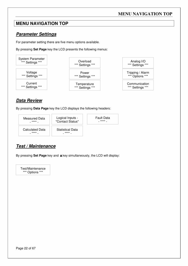
MENU NAVIGATION TOP
Parameter Settings For parameter setting there are five menu options available. By pressing Set Page key the LCD presents the following menus:
System Parameter
*** Settings ***
Overload
*** Settings ***
Analog I/O
*** Settings ***
Voltage
*** Settings ***
Power *** Settings ***
Tripping / Alarm *** Options ***
Current *** Settings ***
Temperature *** Settings ***
Communication *** Settings ***
Data Review By pressing Data Page key the LCD displays the following headers:
Measured Data
- **** -
Logical Inputs - *Contact Status*
Fault Data - **** -
Calculated Data - **** -
Statistical Data - **** -
Test / Maintenance By pressing Set Page key and key simultaneously, the LCD will display:
Test/Maintenance
*** Options ***
MENU NAVIGATION TOP
Page 23 of 67
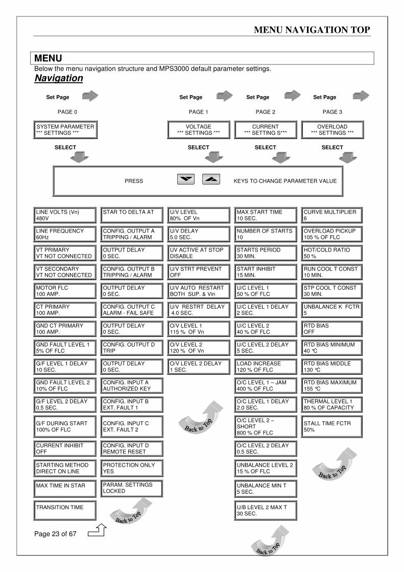
MENU Below the menu navigation structure and MPS3000 default parameter settings.
Navigation
Set Page Set Page Set Page Set Page
PAGE 0 PAGE 1 PAGE 2 PAGE 3
SYSTEM PARAMETER *** SETTINGS ***
VOLTAGE
*** SETTINGS ***
CURRENT *** SETTING S***
OVERLOAD
*** SETTINGS ***
SELECT SELECT SELECT SELECT
PRESS KEYS TO CHANGE PARAMETER VALUE
LINE VOLTS (Vn) 480V
STAR TO DELTA AT
U/V LEVEL 80% OF Vn
MAX START TIME 10 SEC.
CURVE MULTIPLIER 6
LINE FREQUENCY 60Hz
CONFIG. OUTPUT A TRIPPING / ALARM
U/V DELAY 5.0 SEC.
NUMBER OF STARTS 10
OVERLOAD PICKUP 105 % OF FLC
VT PRIMARY VT NOT CONNECTED
OUTPUT DELAY 0 SEC.
UV ACTIVE AT STOP DISABLE
STARTS PERIOD 30 MIN.
HOT/COLD RATIO 50 %
VT SECONDARY VT NOT CONNECTED
CONFIG. OUTPUT B TRIPPING / ALARM
U/V STRT PREVENT OFF
START INHIBIT 15 MIN.
RUN COOL T CONST 10 MIN.
MOTOR FLC 100 AMP.
OUTPUT DELAY 0 SEC.
U/V AUTO RESTART BOTH SUP. & Vin
U/C LEVEL 1 50 % OF FLC
STP COOL T CONST 30 MIN.
CT PRIMARY 100 AMP.
CONFIG. OUTPUT C ALARM - FAIL SAFE
U/V RESTRT DELAY 4.0 SEC.
U/C LEVEL 1 DELAY 2 SEC.
UNBALANCE K FCTR 5
GND CT PRIMARY 100 AMP.
OUTPUT DELAY 0 SEC.
O/V LEVEL 1 115 % OF Vn
U/C LEVEL 2 40 % OF FLC
RTD BIAS OFF
GND FAULT LEVEL 1 5% OF FLC
CONFIG. OUTPUT D TRIP
O/V LEVEL 2 120 % OF Vn
U/C LEVEL 2 DELAY 5 SEC.
RTD BIAS MINIMUM 40 °C
G/F LEVEL 1 DELAY 10 SEC.
OUTPUT DELAY 0 SEC.
O/V LEVEL 2 DELAY 1 SEC.
LOAD INCREASE 120 % OF FLC
RTD BIAS MIDDLE 130 °C
GND FAULT LEVEL 2 10% OF FLC
CONFIG. INPUT A AUTHORIZED KEY
O/C LEVEL 1 – JAM 400 % OF FLC
RTD BIAS MAXIMUM 155 °C
G/F LEVEL 2 DELAY 0.5 SEC.
CONFIG. INPUT B EXT. FAULT 1
O/C LEVEL 1 DELAY 2.0 SEC.
THERMAL LEVEL 1 80 % OF CAPACITY
G/F DURING START 100% OF FLC
CONFIG. INPUT C EXT. FAULT 2
O/C LEVEL 2 – SHORT 800 % OF FLC
STALL TIME FCTR 50%
CURRENT INHIBIT OFF
CONFIG. INPUT D REMOTE RESET
O/C LEVEL 2 DELAY 0.5 SEC.
STARTING METHOD DIRECT ON LINE
PROTECTION ONLY YES
UNBALANCE LEVEL 2 15 % OF FLC
MAX TIME IN STAR
PARAM. SETTINGS LOCKED
UNBALANCE MIN T 5 SEC.
TRANSITION TIME
U/B LEVEL 2 MAX T 30 SEC.
MENU
Page 24 of 67
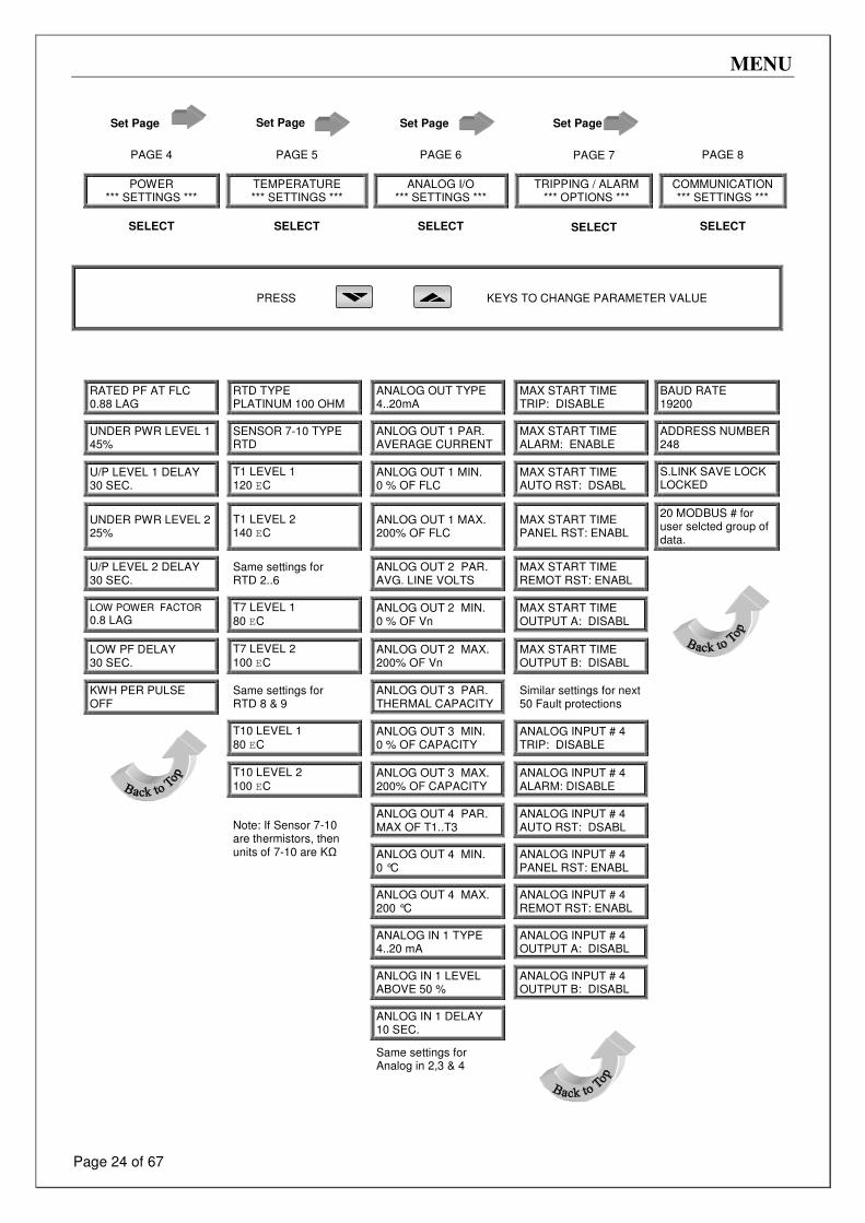
Set Page Set Page Set Page Set Page
PAGE 4 PAGE 5 PAGE 6
PAGE 7
PAGE 8
POWER
*** SETTINGS ***
TEMPERATURE *** SETTINGS ***
ANALOG I/O
*** SETTINGS ***
TRIPPING / ALARM *** OPTIONS ***
COMMUNICATION *** SETTINGS ***
SELECT SELECT SELECT SELECT
SELECT
PRESS KEYS TO CHANGE PARAMETER VALUE
RATED PF AT FLC 0.88 LAG
RTD TYPE PLATINUM 100 OHM
ANALOG OUT TYPE 4..20mA
MAX START TIME TRIP: DISABLE
BAUD RATE 19200
UNDER PWR LEVEL 1 45%
SENSOR 7-10 TYPE RTD
ANLOG OUT 1 PAR. AVERAGE CURRENT
MAX START TIME ALARM: ENABLE
ADDRESS NUMBER 248
U/P LEVEL 1 DELAY 30 SEC.
T1 LEVEL 1 120 EC
ANLOG OUT 1 MIN. 0 % OF FLC
MAX START TIME AUTO RST: DSABL
S.LINK SAVE LOCK LOCKED
UNDER PWR LEVEL 2 25%
T1 LEVEL 2 140 EC
ANLOG OUT 1 MAX. 200% OF FLC
MAX START TIME PANEL RST: ENABL
20 MODBUS # for user selcted group of data.
U/P LEVEL 2 DELAY 30 SEC.
Same settings for RTD 2..6
ANLOG OUT 2 PAR. AVG. LINE VOLTS
MAX START TIME REMOT RST: ENABL
LOW POWER FACTOR
0.8 LAG
T7 LEVEL 1 80 EC
ANLOG OUT 2 MIN. 0 % OF Vn
MAX START TIME OUTPUT A: DISABL
LOW PF DELAY 30 SEC.
T7 LEVEL 2 100 EC
ANLOG OUT 2 MAX. 200% OF Vn
MAX START TIME OUTPUT B: DISABL
KWH PER PULSE OFF
Same settings for RTD 8 & 9
ANLOG OUT 3 PAR. THERMAL CAPACITY
Similar settings for next 50 Fault protections
T10 LEVEL 1 80 EC
ANLOG OUT 3 MIN. 0 % OF CAPACITY
ANALOG INPUT # 4 TRIP: DISABLE
T10 LEVEL 2 100 EC
ANLOG OUT 3 MAX. 200% OF CAPACITY
ANALOG INPUT # 4 ALARM: DISABLE
ANLOG OUT 4 PAR. MAX OF T1..T3
ANALOG INPUT # 4 AUTO RST: DSABL
Note: If Sensor 7-10 are thermistors, then units of 7-10 are KΩ
ANLOG OUT 4 MIN. 0 °C
ANALOG INPUT # 4 PANEL RST: ENABL
ANLOG OUT 4 MAX. 200 °C
ANALOG INPUT # 4 REMOT RST: ENABL
ANALOG IN 1 TYPE 4..20 mA
ANALOG INPUT # 4 OUTPUT A: DISABL
ANLOG IN 1 LEVEL ABOVE 50 %
ANALOG INPUT # 4 OUTPUT B: DISABL
ANLOG IN 1 DELAY 10 SEC.
Same settings for Analog in 2,3 & 4
MENU
Page 25 of 67
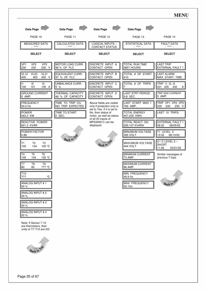
Data Page Data Page Data Page Data Page
PAGE 10 PAGE 11 PAGE 12
PAGE 13 PAGE 14
MEASURED DATA
- **** -
CALCULATED DATA - **** -
LOGICAL INPUTS – CONTACT STATUS
STATISTICAL DATA
- **** - FAULT DATA
- **** -
SELECT SELECT SELECT SELECT SELECT
VP1 VP2 VP3 230 230 230 V
MOTOR LOAD CURR. 96 % OF FLC
DISCRETE INPUT A CONTACT OPEN
TOTAL RUN TIME 9857 HOURS
LAST TRIP EXTERNAL FAULT 1
VL12 VL23 VL31 400 400 400 V
EQUIVALENT CURR. 97 % OF FLC
DISCRETE INPUT B CONTACT OPEN
TOTAL # OF START 410
LAST ALARM MAX START TIME
I1 I2 I3 100 101 100 A
UNBALANCE CURR. 5 %
DISCRETE INPUT C CONTACT OPEN
TOTAL # OF TRIPS 7
TRIP I1, I2, I3 431 435 432 A
GROUND CURRENT 0 AMP.
THERMAL CAPACITY 48 % OF CAPACITY
DISCRETE INPUT D CONTACT OPEN
LAST STRT PERIOD 9.8 SEC.
TRIP GND CURRENT
0 AMP.
FREQUENCY 50.0 Hz
TIME TO TRIP O/L NO TRIP EXPECTED
LAST START MAX I 760 AMP.
TRIP VP1, VP2, VP3 230 230 230 V
POWER 563.2 KW
TIME TO START 0 SEC.
TOTAL ENERGY 457,235 KWH
LAST 10 TRIPS:
REACTIVE POWER 601.3 KVAR
Above fields are visible only if protection only is set to Yes. If it is set to No, then status of motor, as well as status of all 20 inputs of MPS3000-C can be displayed.
TOTAL REACT. EN. 265,107 KVARH
EXTERNAL FAULT 1 08:32 08/05/02
POWER FACTOR 0.88
MINUMUM VOLTAGE 395 VOLT
T1 LEVEL 2 13:33 06/13/02
T1 T2 T3 105 104 105 °C
MAXUMUM VOLTAGE 404 VOLT
O / C LEVEL 2 –SHORT 11:26 03/21/02
T4 T5 T6 105 104 105 °C
MINIMUM CURRENT 73 AMP.
Similar messages of previous 7 trips.
T7 T8 T9 80 85 ??? °C
MAXIMUM CURRENT 86 AMP.
T10 ??? °C
MIN. FREQUENCY 49.9 Hz
ANALOG INPUT # 1 20 %
MAX. FREQUENCY 50.1Hz
ANALOG INPUT # 2 20 %
ANALOG INPUT # 3 20 %
ANALOG INPUT # 4 20 %
Note: If Sensor 7-10 are thermistors, then units of T7-T10 are KΩ
SET PAGE - MENUS
Page 26 of 67
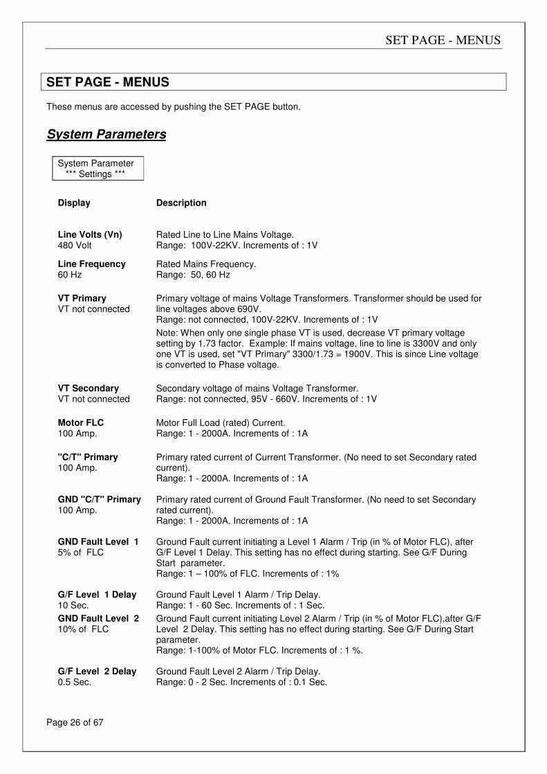
SET PAGE - MENUS These menus are accessed by pushing the SET PAGE button.
System Parameters
System Parameter *** Settings ***
Display
Description
Line Volts (Vn) 480 Volt
Rated Line to Line Mains Voltage. Range: 100V-22KV. Increments of : 1V
Line Frequency 60 Hz
Rated Mains Frequency. Range: 50, 60 Hz
VT Primary VT not connected
Primary voltage of mains Voltage Transformers. Transformer should be used for line voltages above 690V. Range: not connected, 100V-22KV. Increments of : 1V
Note: When only one single phase VT is used, decrease VT primary voltage setting by 1.73 factor. Example: If mains voltage, line to line is 3300V and only one VT is used, set "VT Primary" 3300/1.73 = 1900V. This is since Line voltage is converted to Phase voltage.
VT Secondary VT not connected
Secondary voltage of mains Voltage Transformer. Range: not connected, 95V - 660V. Increments of : 1V
Motor FLC 100 Amp.
Motor Full Load (rated) Current. Range: 1 - 2000A. Increments of : 1A
"C/T" Primary 100 Amp.
Primary rated current of Current Transformer. (No need to set Secondary rated current). Range: 1 - 2000A. Increments of : 1A
GND "C/T" Primary 100 Amp.
Primary rated current of Ground Fault Transformer. (No need to set Secondary rated current). Range: 1 - 2000A. Increments of : 1A
GND Fault Level 1 5% of FLC
Ground Fault current initiating a Level 1 Alarm / Trip (in % of Motor FLC), after G/F Level 1 Delay. This setting has no effect during starting. See G/F During Start parameter. Range: 1 – 100% of FLC. Increments of : 1%
G/F Level 1 Delay 10 Sec.
Ground Fault Level 1 Alarm / Trip Delay. Range: 1 - 60 Sec. Increments of : 1 Sec.
GND Fault Level 2 10% of FLC
Ground Fault current initiating Level 2 Alarm / Trip (in % of Motor FLC),after G/F Level 2 Delay. This setting has no effect during starting. See G/F During Start parameter. Range: 1-100% of Motor FLC. Increments of : 1 %.
G/F Level 2 Delay 0.5 Sec.
Ground Fault Level 2 Alarm / Trip Delay. Range: 0 - 2 Sec. Increments of : 0.1 Sec.
SET PAGE - MENUS
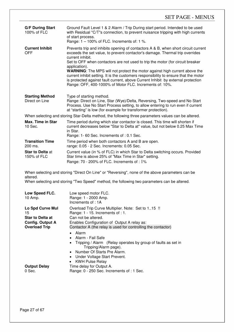
Page 27 of 67
G/F During Start 100% of FLC
Ground Fault Level 1 & 2 Alarm / Trip During start period. Intended to be used with Residual "C/T"s connection, to prevent nuisance tripping with high currents of start process. Range: 1 – 100% of FLC. Increments of: 1 %.
Current Inhibit OFF
Prevents trip and inhibits opening of contactors A & B, when short circuit current exceeds the set value, to prevent contactor's damage. Thermal trip overrides current inhibit. Set to OFF when contactors are not used to trip the motor (for circuit breaker application). WARNING: The MPS will not protect the motor against high current above the current inhibit setting. It is the customers responsibility to ensure that the motor is protected against fault current, above Current Inhibit by external protection Range: OFF, 400-1000% of Motor FLC. Increments of: 10%.
Starting Method Direct on Line
Type of starting method. Range: Direct on Line, Star (Wye)/Delta, Reversing, Two-speed and No Start Process. Use No Start Process setting, to allow entering to run even if current at “starting” is low (for example for transformer protection).
When selecting and storing Star-Delta method, the following three parameters values can be altered.
Max. Time in Star 10 Sec.
Time period during which star contactor is closed. This time will shorten if current decreases below "Star to Delta at" value, but not below 0.25 Max Time in Star. Range: 1- 60 Sec. Increments of : 0.1 Sec.
Transition Time 200 ms.
Time period when both contactors A and B are open. range: 0.05 - 2 Sec. Increments: 0.05 Sec.
Star to Delta at 150% of FLC
Current value (in % of FLC) in which Star to Delta switching occurs. Provided Star time is above 25% of "Max Time in Star" setting.
Range: 70 - 200% of FLC. Increments of : 1%
When selecting and storing "Direct On Line" or "Reversing", none of the above parameters can be altered. When selecting and storing "Two Speed" method, the following two parameters can be altered.
Low Speed FLC. 10 Amp.
Low speed motor FLC. Range: 1 - 2000 Amp. Increments of : 1A
Lo Spd Curve Mul 15
Overload Trip Curve Multiplier. Note: Set to 1..15 !! Range: 1 - 15. Increments of : 1.
Star to Delta at Can not be altered.
Config. Output A Overload Trip
Enables Configuration of Output A relay as: Contactor A (the relay is used for controlling the contactor)
• Alarm
• Alarm - Fail Safe
• Tripping / Alarm (Relay operates by group of faults as set in Tripping/Alarm page).
• Number Of Starts Pre Alarm.
• Under Voltage Start Prevent.
• KWH Pulse Relay
Output Delay 0 Sec.
Time delay for Output A. Range: 0 - 250 Sec. Increments of : 1 Sec.
SET PAGE - MENUS
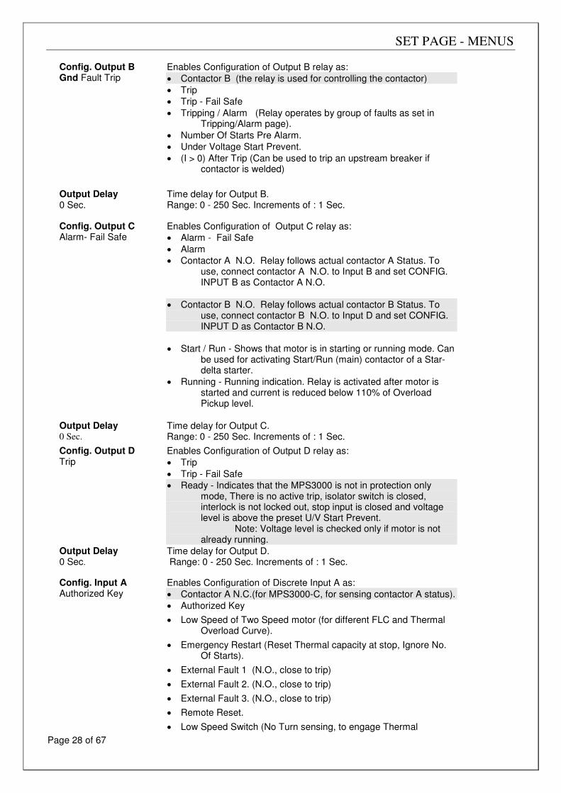
Page 28 of 67
Config. Output B Gnd Fault Trip
Enables Configuration of Output B relay as:
• Contactor B (the relay is used for controlling the contactor)
• Trip
• Trip - Fail Safe
• Tripping / Alarm (Relay operates by group of faults as set in Tripping/Alarm page).
• Number Of Starts Pre Alarm.
• Under Voltage Start Prevent.
• (I > 0) After Trip (Can be used to trip an upstream breaker if contactor is welded)
Output Delay 0 Sec.
Time delay for Output B. Range: 0 - 250 Sec. Increments of : 1 Sec.
Config. Output C
Alarm- Fail Safe
Enables Configuration of Output C relay as:
• Alarm - Fail Safe
• Alarm
• Contactor A N.O. Relay follows actual contactor A Status. To use, connect contactor A N.O. to Input B and set CONFIG. INPUT B as Contactor A N.O.
• Contactor B N.O. Relay follows actual contactor B Status. To use, connect contactor B N.O. to Input D and set CONFIG. INPUT D as Contactor B N.O.
• Start / Run - Shows that motor is in starting or running mode. Can be used for activating Start/Run (main) contactor of a Star-delta starter.
• Running - Running indication. Relay is activated after motor is started and current is reduced below 110% of Overload Pickup level.
Output Delay 0 Sec.
Time delay for Output C. Range: 0 - 250 Sec. Increments of : 1 Sec.
Config. Output D Trip
Enables Configuration of Output D relay as:
• Trip
• Trip - Fail Safe
• Ready - Indicates that the MPS3000 is not in protection only mode, There is no active trip, isolator switch is closed, interlock is not locked out, stop input is closed and voltage level is above the preset U/V Start Prevent. Note: Voltage level is checked only if motor is not already running.
Output Delay 0 Sec.
Time delay for Output D. Range: 0 - 250 Sec. Increments of : 1 Sec.
Config. Input A
Authorized Key
Enables Configuration of Discrete Input A as:
• Contactor A N.C.(for MPS3000-C, for sensing contactor A status).
• Authorized Key
• Low Speed of Two Speed motor (for different FLC and Thermal Overload Curve).
• Emergency Restart (Reset Thermal capacity at stop, Ignore No. Of Starts).
• External Fault 1 (N.O., close to trip)
• External Fault 2. (N.O., close to trip)
• External Fault 3. (N.O., close to trip)
• Remote Reset.
• Low Speed Switch (No Turn sensing, to engage Thermal
SET PAGE - MENUS
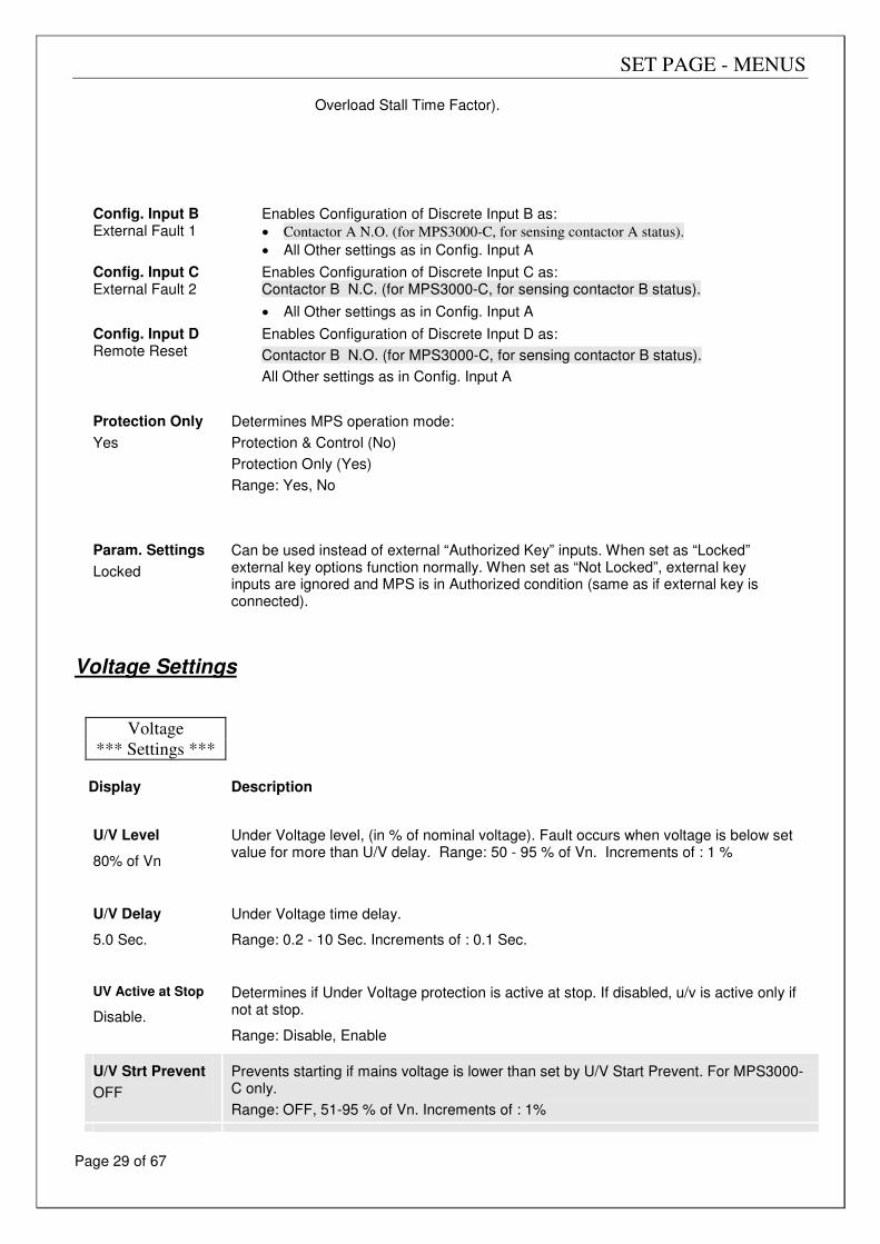
Page 29 of 67
Overload Stall Time Factor).
Config. Input B
External Fault 1
Enables Configuration of Discrete Input B as:
• Contactor A N.O. (for MPS3000-C, for sensing contactor A status).
• All Other settings as in Config. Input A
Config. Input C External Fault 2
Enables Configuration of Discrete Input C as: Contactor B N.C. (for MPS3000-C, for sensing contactor B status).
• All Other settings as in Config. Input A
Config. Input D Remote Reset
Enables Configuration of Discrete Input D as:
Contactor B N.O. (for MPS3000-C, for sensing contactor B status).
All Other settings as in Config. Input A
Protection Only
Yes
Determines MPS operation mode:
Protection & Control (No)
Protection Only (Yes)
Range: Yes, No
Param. Settings
Locked
Can be used instead of external “Authorized Key” inputs. When set as “Locked” external key options function normally. When set as “Not Locked”, external key inputs are ignored and MPS is in Authorized condition (same as if external key is connected).
Voltage Settings
Voltage
*** Settings ***
Display Description
U/V Level
80% of Vn
Under Voltage level, (in % of nominal voltage). Fault occurs when voltage is below set value for more than U/V delay. Range: 50 - 95 % of Vn. Increments of : 1 %
U/V Delay
5.0 Sec.
Under Voltage time delay.
Range: 0.2 - 10 Sec. Increments of : 0.1 Sec.
UV Active at Stop
Disable.
Determines if Under Voltage protection is active at stop. If disabled, u/v is active only if not at stop.
Range: Disable, Enable
U/V Strt Prevent
OFF
Prevents starting if mains voltage is lower than set by U/V Start Prevent. For MPS3000-C only.
Range: OFF, 51-95 % of Vn. Increments of : 1%
SET PAGE - MENUS
Page 30 of 67
U/V Auto Restart
Disable
Enables / Disables the auto Restart features.
• Set to “Disable”, if Restart is not required.
• Set to “Measured Voltage”, if control power supply (19-20) is stable during mains failure (powered from UPS or DC). Mains Failure is detected and causes motor stop, when voltage decreases below 65% of rated voltage. Mains restoration is detected when voltage increases to above 85% of rated voltage.
• Set to “Both Sup & Vin” for normal AC mains (both measured voltage (35,37) and control power supply (19,20) turn off during mains failure).
Note: Setting as “Auxiliary Supply” may not cause restart, for mains failure duration of less than 0.5sec.
Restart occurs only if:
• Motor was Starting/Running before mains failure
• Turn off time is 0.1 - 4 sec. (±25%)
Range: Disable, Auxiliary Supply, Measured Voltage, Both Sup. & Vin U/V Restart Delay
4 Sec.
Time delay for the auto Restart feature, counted from mains (auxiliary supply or measured voltage, as set on u/v Start Prevent) restoration
Range: 0.4 – 25 Sec. O/V Level 1 115% of Vn
Over Voltage Level 1. Fault occurs when voltage is above set value for more than 1 second (fixed delay). Range: 100 - 120 % of Un. Increments of : 1%
O/V Level 2
120% of Vn
Over Voltage Level 2. Fault occurs when voltage is above set value for more than O/V LEVEL 2 Delay. Range: 100 - 120 % of Un. Increments of : 1%
O/V Level 2 Delay
1 Sec.
Over Voltage Level 2 delays.
Range: 1 - 100 Sec. Increments of : 1Sec.
SET PAGE - MENUS
Page 31 of 67
Current Settings
Current
*** Settings ***
Display
Description
Max Start Time
10 Sec.
Maximum Permitted starting time until current is reduced to 110% of Overload Pickup setting parameter. Protects the motor against too long starting.
Range: 1 – 250 Sec. Increments of : 1 Sec.
Number of Starts
10
Maximum Permitted number of starts during "Starts Period".
Range: 1 – 10. Increments of : 1
Starts Period
30 min.
Time period during which the number of starts is counted.
Range: 1 - 60 min. Increments of : 1 min.
Start Inhibit
15 min.
Time period after which auto reset is prevented (even if enabled) after "Too Many Starts" trip.
Range: 1 - 60 min. Increments of: 1 min.
U/C Level 1
50% of FLC
Under Current Level 1. Fault occurs when current is below the set parameter for more than U/C Level 1 Delay.
Range: 10 - 90 % of Motor FLC. Increments of : 1%
U/C Level 1 Delay
2 Sec.
Under Current Level 1 Delay.
Range: 1 - 60 Sec. Increments of : 1 Sec.
U/C Level 2
40% of FLC
Under Current Level 2.
Range: 10 - 90 % of Motor FLC. Increments of : 1%
U/C Level 2 Delay
5 Sec.
Under Current Level 2 Delay.
Range: 1 - 60 Sec. Increments of : 1 Sec.
Load Increase
120% of FLC
Load Increase. Fault occurs when current is above the set parameter for more than fixed time period of 5 seconds. Range: 60 - 150% of Motor FLC. Increments of : 1%
O/C Level 1- Jam
400 % of FLC
Over Current Level 1- Jam (stall) protection. Operative after start process ended. Indicates that current exceeded set value for more than O/C Level 1 Delay.
Range: 100 - 500 % of Motor FLC. Increments of : 10%
O/C Level 1 Delay
2.0 Sec.
Time delay for O/C Level 1.
Range: 0.5 - 10 Sec. Increments of : 0.1 Sec.
O/C Level 2- Short
800 % of FLC
Over Current Level 2- Short circuit protection. Operative during starting and running. Indicates that current exceeded set value for more than O/C Level 2 Delay.
Range: 400 - 1200 % of Motor FLC. Increments of : 10%
SET PAGE - MENUS
Page 32 of 67
O/C Level 2 Delay
0.5 Sec.
Time delay for Over Current Level 2
Note: When set to 0, actual delay is less than 70mSec.
Range: 0 - 4 Sec. Increments of : 0.1 Sec.
Unbalance Level 2
15 % of FLC
Unbalance Current. Fault occurs only if actual Unbalance is greater than the set value. See Figure 6 for time delay.
Note - Unbalance Current level 1 will be activated when Unbalance Current exceeds 50% of the Unbalance Level 2 for more than 1 second (fixed time period).
Range: 10 - 40 % of Motor FLC. Increments of : 1%
Unbalance Min T
5 Sec.
Unbalance Minimum response time for both Alarm and Trip.
Range: 1 - 30 Sec. Increments of : 1 Sec.
U/B Level 2 Max T
30 Sec.
Unbalance curve selection. see p37
Time delay at 10% of Unbalance. Fault time is inversely related to the actual unbalance (See page 37).
Range: 20 - 120 Sec. Increments of : 1 Sec.

SET PAGE - MENUS
Page 33 of 67
Overload Settings
OVERLOAD
*** SETTINGS ***
Display Description
Curve Multiplier
6
Overload Curve Multiplier. Shifts the entire Overload Curve.
Range: 1 - 15. Increments of : 1.
Overload Pickup 105% of FLC
Lower threshold for O/L protection. Below this threshold, O/L fault cannot occur.
Range: 60 - 130 % of Motor FLC. Increments of : 1%
Hot/Cold Ratio
50%
The ratio between thermal Capacity available for starting a hot motor and thermal capacity available for starting a cold motor. (A higher setting allows for a longer starting time of hot motor before tripping).
Range: 20- 100% of Thermal Capacity. Increments of: 1%.
Run Cool T Const
10 min.
Cooling Time Constant while motor is running. When Current is smaller than Overload Pickup, Thermal Capacity is exponentially reduced to simulate motor cooling to (100-Hot/Cold ratio)
Range: 1 – 240 min. Increments of: 1min.
Stp Cool T Const
30 min.
Cooling Time Constant while motor is stopped. This time constant is normally significantly longer than the Cooling Time Constant of a running motor.
Range: 1 – 240 min. Increments of: 1min.
Unbalance K Fctr
5
Unbalance K Factor. Used to increase the motor’s equivalent current as a result of Unbalance currents. The Unbalance currents cause a negative Sequence Currents. The MPS3000 measures the Negative as well as positive sequence currents and uses their values to calculate the equivalent current, given by:
LEQ = I% * √ (1 + K * (IN/IP)² )
Where:
I% - Motor RMS (average of the three phases) current
IN – Negative sequence Current
IP – Positive Sequence current
Range: 0 – 15. Increments of: 1
RTD Bias
OFF
RTD Bias allows to disable RTD Bias, to use max of RTD1..3 or to use max of RTD1..6 for the temperature bias.
Note that when enabled, the RTD BIAS can only increase the Thermal Capacity value. It can never decrease it.
Range: OFF, T1..T3, T1..T6
RTD Bias Minimum
40 °C
RTD Minimum is the minimum bias temperature. Below this temperature, the RTD bias has no effect on the thermal model.
Range: 10°C..RTD Bias Middle. Increment of: 1°C.
RTD Bias Middle
130 °C
Set RTD Middle to the normal expected working temperature with 100% load. At this point, the thermal capacity (at steady state) should be 100 – Hot/Cold ratio.
Range: RTD Minimum…RTD Maximum. Increment of: 1°C.
RTD Bias
Set RTD Max to the maximum allowed working temperature. At this point, the thermal
SET PAGE - MENUS
Page 34 of 67
maximum
155 °C
capacity should be 100%.
Range: RTD Middle…250°C. Increment of: 1°C.
Thermal Level 1 80% of Capacity
Thermal Capacity level 1. Normally used for alarm indication.
Range: 50 - 99 % of maximum thermal capacity. Increments of : 1%
Stall Time Fact
50%
Stall Time Factor. The ratio between motor thermal time constant when speed switch is closed (indicating slow speed) to thermal time constant with open speed switch - (indicating high speed). Operative when speed switch is used.
Range: 20 - 100 %. Increments of: 1%
SET PAGE - MENUS
Page 35 of 67
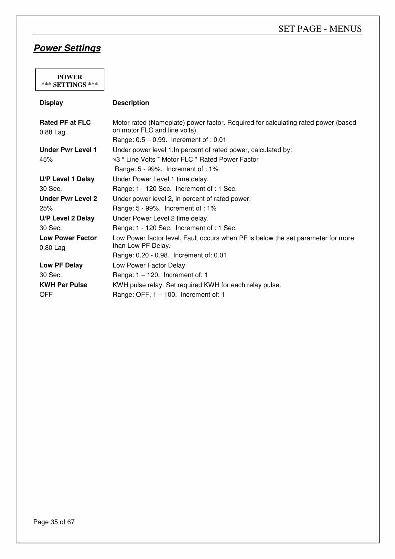
Power Settings
POWER
*** SETTINGS ***
Display Description
Rated PF at FLC
0.88 Lag
Motor rated (Nameplate) power factor. Required for calculating rated power (based on motor FLC and line volts).
Range: 0.5 – 0.99. Increment of : 0.01
Under Pwr Level 1
45%
Under power level 1.In percent of rated power, calculated by:
√3 * Line Volts * Motor FLC * Rated Power Factor
Range: 5 - 99%. Increment of : 1%
U/P Level 1 Delay
30 Sec.
Under Power Level 1 time delay.
Range: 1 - 120 Sec. Increment of : 1 Sec.
Under Pwr Level 2
25%
Under power level 2, in percent of rated power.
Range: 5 - 99%. Increment of : 1%
U/P Level 2 Delay
30 Sec.
Under Power Level 2 time delay.
Range: 1 - 120 Sec. Increment of : 1 Sec.
Low Power Factor
0.80 Lag
Low Power factor level. Fault occurs when PF is below the set parameter for more than Low PF Delay.
Range: 0.20 - 0.98. Increment of: 0.01
Low PF Delay
30 Sec.
Low Power Factor Delay
Range: 1 – 120. Increment of: 1
KWH Per Pulse
OFF
KWH pulse relay. Set required KWH for each relay pulse.
Range: OFF, 1 – 100. Increment of: 1
SET PAGE - MENUS
Page 36 of 67
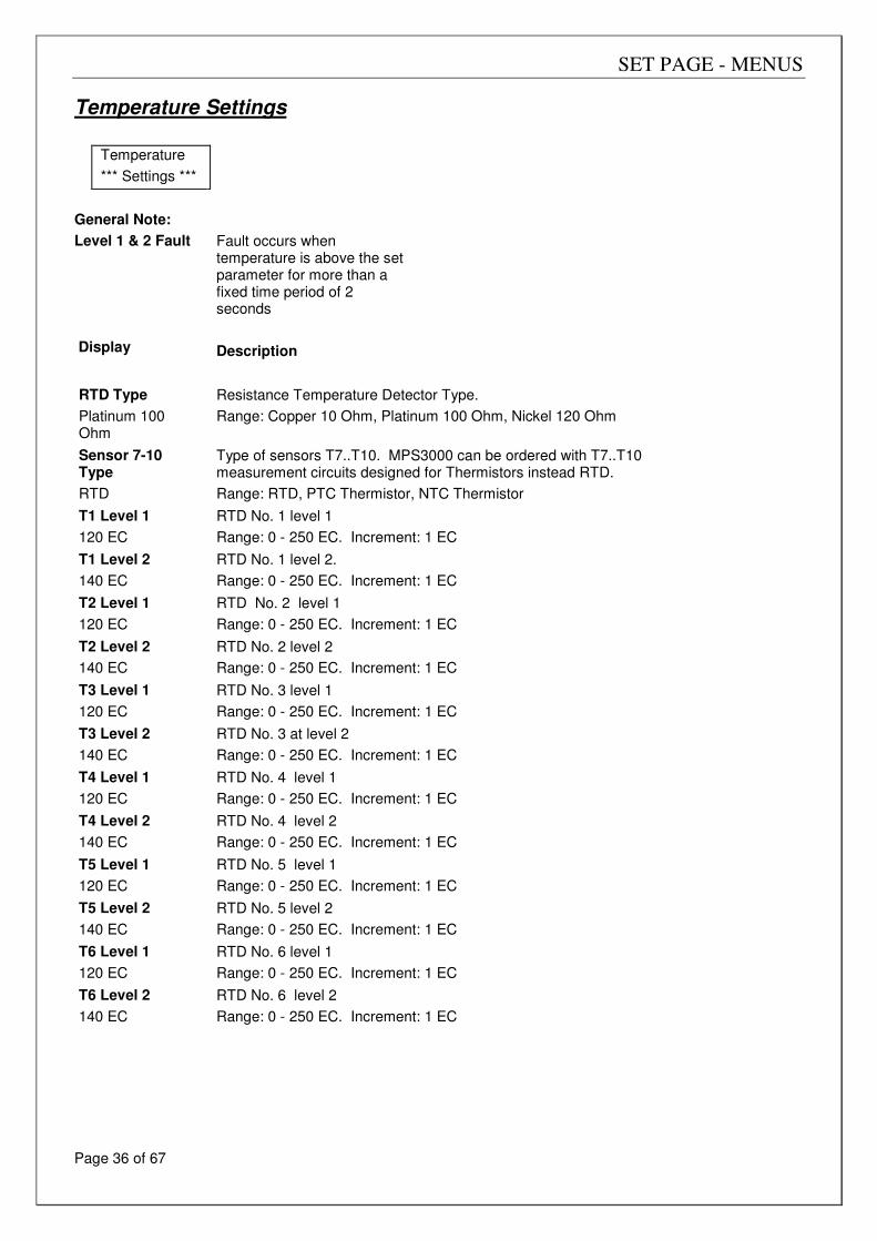
Temperature Settings
Temperature
*** Settings ***
General Note:
Level 1 & 2 Fault
Display
Fault occurs when temperature is above the set parameter for more than a fixed time period of 2 seconds
Description
RTD Type
Platinum 100 Ohm
Resistance Temperature Detector Type.
Range: Copper 10 Ohm, Platinum 100 Ohm, Nickel 120 Ohm
Sensor 7-10 Type
RTD
Type of sensors T7..T10. MPS3000 can be ordered with T7..T10 measurement circuits designed for Thermistors instead RTD.
Range: RTD, PTC Thermistor, NTC Thermistor
T1 Level 1
120 EC
RTD No. 1 level 1
Range: 0 - 250 EC. Increment: 1 EC
T1 Level 2
140 EC
RTD No. 1 level 2.
Range: 0 - 250 EC. Increment: 1 EC
T2 Level 1
120 EC
RTD No. 2 level 1
Range: 0 - 250 EC. Increment: 1 EC
T2 Level 2
140 EC
RTD No. 2 level 2
Range: 0 - 250 EC. Increment: 1 EC
T3 Level 1
120 EC
RTD No. 3 level 1
Range: 0 - 250 EC. Increment: 1 EC
T3 Level 2
140 EC
RTD No. 3 at level 2
Range: 0 - 250 EC. Increment: 1 EC
T4 Level 1
120 EC
RTD No. 4 level 1
Range: 0 - 250 EC. Increment: 1 EC
T4 Level 2
140 EC
RTD No. 4 level 2
Range: 0 - 250 EC. Increment: 1 EC
T5 Level 1
120 EC
RTD No. 5 level 1
Range: 0 - 250 EC. Increment: 1 EC
T5 Level 2
140 EC
RTD No. 5 level 2
Range: 0 - 250 EC. Increment: 1 EC
T6 Level 1
120 EC
RTD No. 6 level 1
Range: 0 - 250 EC. Increment: 1 EC
T6 Level 2
140 EC
RTD No. 6 level 2
Range: 0 - 250 EC. Increment: 1 EC
SET PAGE - MENUS
Page 37 of 67
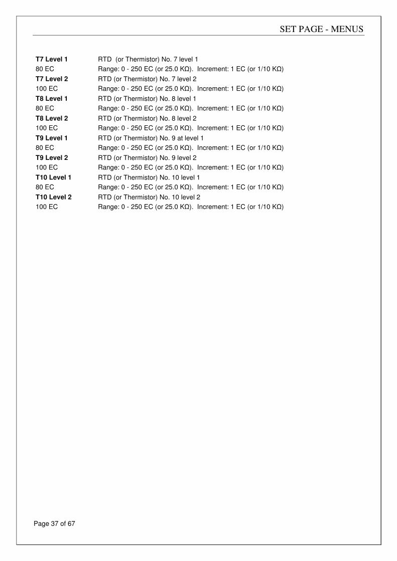
T7 Level 1
80 EC
RTD (or Thermistor) No. 7 level 1
Range: 0 - 250 EC (or 25.0 KΩ). Increment: 1 EC (or 1/10 KΩ)
T7 Level 2
100 EC
RTD (or Thermistor) No. 7 level 2
Range: 0 - 250 EC (or 25.0 KΩ). Increment: 1 EC (or 1/10 KΩ)
T8 Level 1
80 EC
RTD (or Thermistor) No. 8 level 1
Range: 0 - 250 EC (or 25.0 KΩ). Increment: 1 EC (or 1/10 KΩ)
T8 Level 2
100 EC
RTD (or Thermistor) No. 8 level 2
Range: 0 - 250 EC (or 25.0 KΩ). Increment: 1 EC (or 1/10 KΩ)
T9 Level 1
80 EC
RTD (or Thermistor) No. 9 at level 1
Range: 0 - 250 EC (or 25.0 KΩ). Increment: 1 EC (or 1/10 KΩ)
T9 Level 2
100 EC
RTD (or Thermistor) No. 9 level 2
Range: 0 - 250 EC (or 25.0 KΩ). Increment: 1 EC (or 1/10 KΩ)
T10 Level 1
80 EC
RTD (or Thermistor) No. 10 level 1
Range: 0 - 250 EC (or 25.0 KΩ). Increment: 1 EC (or 1/10 KΩ)
T10 Level 2
100 EC
RTD (or Thermistor) No. 10 level 2
Range: 0 - 250 EC (or 25.0 KΩ). Increment: 1 EC (or 1/10 KΩ)
SET PAGE - MENUS
Page 38 of 67
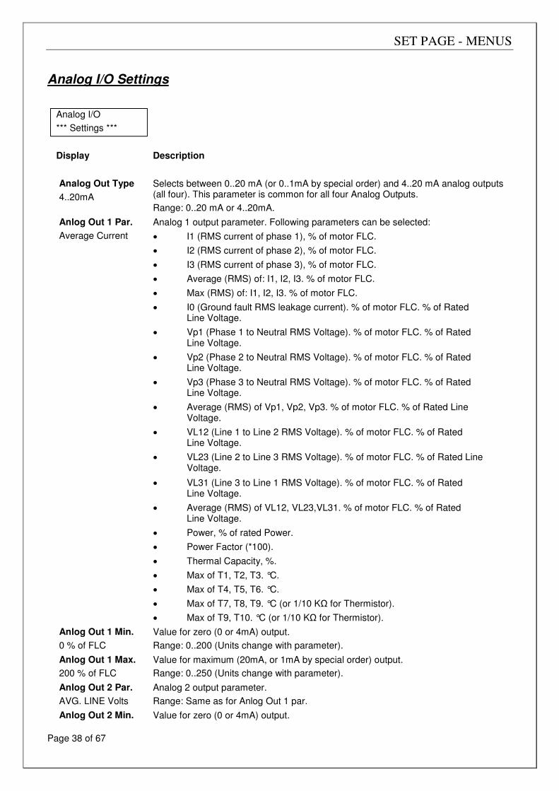
Analog I/O Settings
Analog I/O
*** Settings ***
Display
Description
Analog Out Type
4..20mA
Selects between 0..20 mA (or 0..1mA by special order) and 4..20 mA analog outputs (all four). This parameter is common for all four Analog Outputs.
Range: 0..20 mA or 4..20mA.
Anlog Out 1 Par.
Average Current
Analog 1 output parameter. Following parameters can be selected:
• I1 (RMS current of phase 1), % of motor FLC.
• I2 (RMS current of phase 2), % of motor FLC.
• I3 (RMS current of phase 3), % of motor FLC.
• Average (RMS) of: I1, I2, I3. % of motor FLC.
• Max (RMS) of: I1, I2, I3. % of motor FLC.
• I0 (Ground fault RMS leakage current). % of motor FLC. % of Rated Line Voltage.
• Vp1 (Phase 1 to Neutral RMS Voltage). % of motor FLC. % of Rated Line Voltage.
• Vp2 (Phase 2 to Neutral RMS Voltage). % of motor FLC. % of Rated Line Voltage.
• Vp3 (Phase 3 to Neutral RMS Voltage). % of motor FLC. % of Rated Line Voltage.
• Average (RMS) of Vp1, Vp2, Vp3. % of motor FLC. % of Rated Line Voltage.
• VL12 (Line 1 to Line 2 RMS Voltage). % of motor FLC. % of Rated Line Voltage.
• VL23 (Line 2 to Line 3 RMS Voltage). % of motor FLC. % of Rated Line Voltage.
• VL31 (Line 3 to Line 1 RMS Voltage). % of motor FLC. % of Rated Line Voltage.
• Average (RMS) of VL12, VL23,VL31. % of motor FLC. % of Rated Line Voltage.
• Power, % of rated Power.
• Power Factor (*100).
• Thermal Capacity, %.
• Max of T1, T2, T3. °C.
• Max of T4, T5, T6. °C.
• Max of T7, T8, T9. °C (or 1/10 KΩ for Thermistor).
• Max of T9, T10. °C (or 1/10 KΩ for Thermistor).
Anlog Out 1 Min.
0 % of FLC
Value for zero (0 or 4mA) output.
Range: 0..200 (Units change with parameter).
Anlog Out 1 Max.
200 % of FLC
Value for maximum (20mA, or 1mA by special order) output.
Range: 0..250 (Units change with parameter).
Anlog Out 2 Par.
AVG. LINE Volts
Analog 2 output parameter.
Range: Same as for Anlog Out 1 par.
Anlog Out 2 Min. Value for zero (0 or 4mA) output.
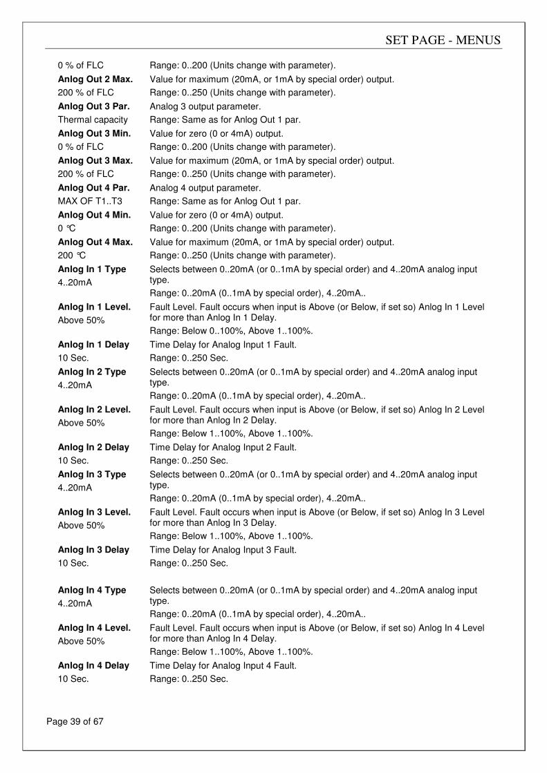
SET PAGE - MENUS
Page 39 of 67
0 % of FLC Range: 0..200 (Units change with parameter).
Anlog Out 2 Max.
200 % of FLC
Value for maximum (20mA, or 1mA by special order) output.
Range: 0..250 (Units change with parameter).
Anlog Out 3 Par.
Thermal capacity
Analog 3 output parameter.
Range: Same as for Anlog Out 1 par.
Anlog Out 3 Min.
0 % of FLC
Value for zero (0 or 4mA) output.
Range: 0..200 (Units change with parameter).
Anlog Out 3 Max.
200 % of FLC
Value for maximum (20mA, or 1mA by special order) output.
Range: 0..250 (Units change with parameter).
Anlog Out 4 Par.
MAX OF T1..T3
Analog 4 output parameter.
Range: Same as for Anlog Out 1 par.
Anlog Out 4 Min.
0 °C
Value for zero (0 or 4mA) output.
Range: 0..200 (Units change with parameter).
Anlog Out 4 Max.
200 °C
Value for maximum (20mA, or 1mA by special order) output.
Range: 0..250 (Units change with parameter).
Anlog In 1 Type
4..20mA
Selects between 0..20mA (or 0..1mA by special order) and 4..20mA analog input type.
Range: 0..20mA (0..1mA by special order), 4..20mA..
Anlog In 1 Level.
Above 50%
Fault Level. Fault occurs when input is Above (or Below, if set so) Anlog In 1 Level for more than Anlog In 1 Delay.
Range: Below 0..100%, Above 1..100%.
Anlog In 1 Delay
10 Sec.
Time Delay for Analog Input 1 Fault.
Range: 0..250 Sec.
Anlog In 2 Type
4..20mA
Selects between 0..20mA (or 0..1mA by special order) and 4..20mA analog input type.
Range: 0..20mA (0..1mA by special order), 4..20mA..
Anlog In 2 Level.
Above 50%
Fault Level. Fault occurs when input is Above (or Below, if set so) Anlog In 2 Level for more than Anlog In 2 Delay.
Range: Below 1..100%, Above 1..100%.
Anlog In 2 Delay
10 Sec.
Time Delay for Analog Input 2 Fault.
Range: 0..250 Sec.
Anlog In 3 Type
4..20mA
Selects between 0..20mA (or 0..1mA by special order) and 4..20mA analog input type.
Range: 0..20mA (0..1mA by special order), 4..20mA..
Anlog In 3 Level.
Above 50%
Fault Level. Fault occurs when input is Above (or Below, if set so) Anlog In 3 Level for more than Anlog In 3 Delay.
Range: Below 1..100%, Above 1..100%.
Anlog In 3 Delay
10 Sec.
Time Delay for Analog Input 3 Fault.
Range: 0..250 Sec.
Anlog In 4 Type
4..20mA
Selects between 0..20mA (or 0..1mA by special order) and 4..20mA analog input type.
Range: 0..20mA (0..1mA by special order), 4..20mA..
Anlog In 4 Level.
Above 50%
Fault Level. Fault occurs when input is Above (or Below, if set so) Anlog In 4 Level for more than Anlog In 4 Delay.
Range: Below 1..100%, Above 1..100%.
Anlog In 4 Delay
10 Sec.
Time Delay for Analog Input 4 Fault.
Range: 0..250 Sec.
SET PAGE - MENUS
Page 40 of 67
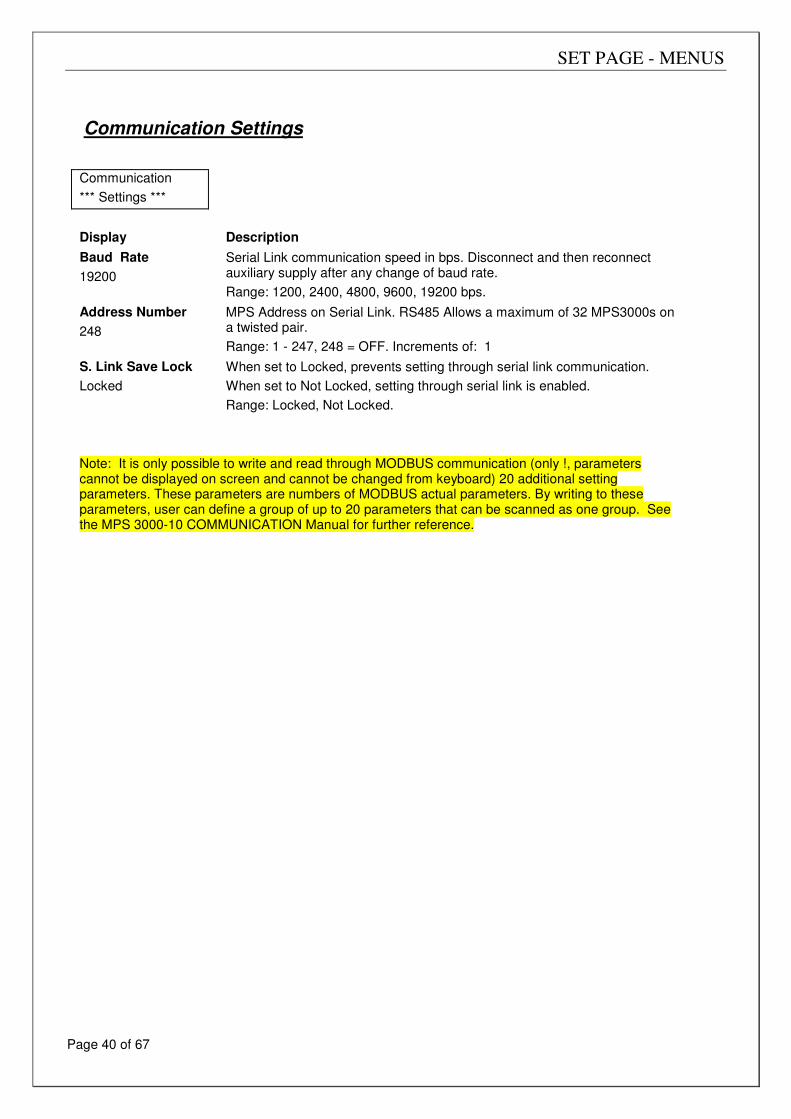
Communication Settings
Communication
*** Settings ***
Display Description
Baud Rate
19200
Serial Link communication speed in bps. Disconnect and then reconnect auxiliary supply after any change of baud rate.
Range: 1200, 2400, 4800, 9600, 19200 bps.
Address Number
248
MPS Address on Serial Link. RS485 Allows a maximum of 32 MPS3000s on a twisted pair.
Range: 1 - 247, 248 = OFF. Increments of: 1
S. Link Save Lock
Locked
When set to Locked, prevents setting through serial link communication.
When set to Not Locked, setting through serial link is enabled.
Range: Locked, Not Locked.
Note: It is only possible to write and read through MODBUS communication (only !, parameters cannot be displayed on screen and cannot be changed from keyboard) 20 additional setting parameters. These parameters are numbers of MODBUS actual parameters. By writing to these parameters, user can define a group of up to 20 parameters that can be scanned as one group. See the MPS 3000-10 COMMUNICATION Manual for further reference.
SET PAGE - MENUS
Page 41 of 67
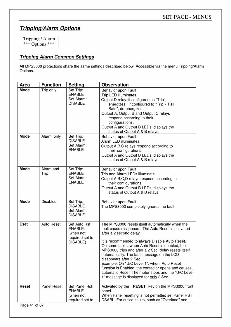
Tripping/Alarm Options
Tripping / Alarm
*** Options ***
Tripping Alarm Common Settings All MPS3000 protections share the same settings described below. Accessible via the menu Tripping/Alarm Options.
Area Function Setting Observation Mode Trip only Set Trip:
ENABLE Set Alarm: DISABLE
Behavior upon Fault
Trip LED illuminates.
Output D relay: if configured as "Trip", energizes. If configured to "Trip - Fail Safe", de-energizes.
Output A, Output B and Output C relays respond according to their configurations.
Output A and Output B LEDs, displays the status of Output A & B relays.
Mode Alarm only Set Trip: DISABLE Set Alarm: ENABLE
Behavior upon Fault
Alarm LED illuminates.
Output A,B,C relays respond according to their configurations,
Output A and Output B LEDs, displays the status of Output A & B relays.
Mode Alarm and Trip
Set Trip: ENABLE Set Alarm: ENABLE
Behavior upon Fault
Trip and Alarm LEDs illuminate.
Output A,B,C,D relays respond according to their configurations,
Output A and Output B LEDs, displays the status of Output A & B relays.
Mode Disabled Set Trip: DISABLE Set Alarm: DISABLE
Behavior upon Fault
The MPS3000 completely ignores the fault.
Eset Auto Reset
Set Auto Rst: ENABLE. (when not required set to DISABLE)
The MPS3000 resets itself automatically when the fault cause disappears. The Auto Reset is activated after a 2 second delay.
It is recommended to always Disable Auto Reset. On some faults, when Auto Reset is enabled, the MPS3000 trips and after a 2 Sec. delay resets itself automatically. The fault message on the LCD disappears after 2 Sec. Example: On "U/C Level 1", when Auto Reset function is Enabled, the contactor opens and causes automatic Reset. The motor stops and the "U/C Level 1" message is displayed for only 2 Sec.
Reset Panel Reset Set Panel Rst: ENABLE. (when not required set to
Activated by the RESET key on the MPS3000 front panel. When Panel resetting is not permitted set Panel RST: DSABL. For critical faults, such as "Overload" and
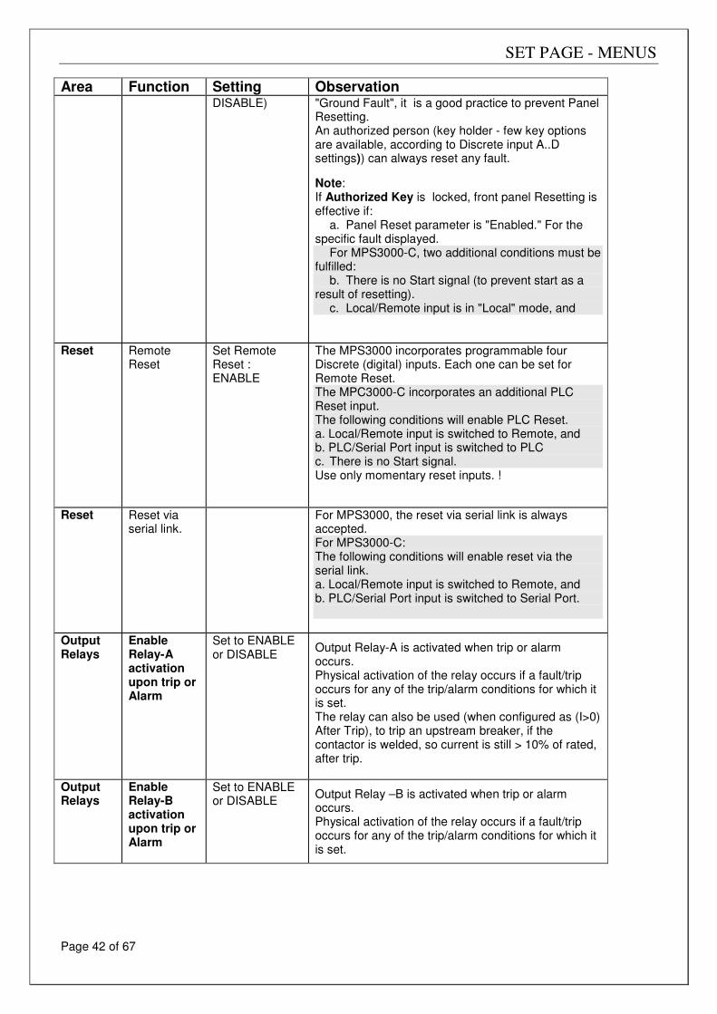
SET PAGE - MENUS
Page 42 of 67
Area Function Setting Observation DISABLE) "Ground Fault", it is a good practice to prevent Panel
Resetting. An authorized person (key holder - few key options are available, according to Discrete input A..D settings)) can always reset any fault.
Note: If Authorized Key is locked, front panel Resetting is effective if:
a. Panel Reset parameter is "Enabled." For the specific fault displayed.
For MPS3000-C, two additional conditions must be fulfilled:
b. There is no Start signal (to prevent start as a result of resetting).
c. Local/Remote input is in "Local" mode, and
Reset Remote Reset
Set Remote Reset : ENABLE
The MPS3000 incorporates programmable four Discrete (digital) inputs. Each one can be set for Remote Reset. The MPC3000-C incorporates an additional PLC Reset input. The following conditions will enable PLC Reset. a. Local/Remote input is switched to Remote, and b. PLC/Serial Port input is switched to PLC c. There is no Start signal. Use only momentary reset inputs. !
Reset Reset via serial link.
For MPS3000, the reset via serial link is always accepted. For MPS3000-C: The following conditions will enable reset via the serial link. a. Local/Remote input is switched to Remote, and b. PLC/Serial Port input is switched to Serial Port.
Output Relays
Enable Relay-A activation upon trip or Alarm
Set to ENABLE or DISABLE
Output Relay-A is activated when trip or alarm occurs. Physical activation of the relay occurs if a fault/trip occurs for any of the trip/alarm conditions for which it is set. The relay can also be used (when configured as (I>0) After Trip), to trip an upstream breaker, if the contactor is welded, so current is still > 10% of rated, after trip.
Output Relays
Enable Relay-B activation upon trip or Alarm
Set to ENABLE or DISABLE
Output Relay –B is activated when trip or alarm occurs. Physical activation of the relay occurs if a fault/trip occurs for any of the trip/alarm conditions for which it is set.
SET PAGE - MENUS
Page 43 of 67
Multiple Alarm/Trip considerations The MPS3000 is designed to accept and store the first alarm it detects. If this alarm has not been reset and an additional alarm occurs, the MPS3000 will not display the second alarm on the LCD nor assign it to the Fault Data page. Example: If "Unbalance Alarm" occurs and then a "Thermal Pre-alarm" occurs, the MPS3000 will continue displaying "Unbalance Alarm" message on both, LCD and Fault Data page. This is to assist the user in establishing the cause of the alarm. In case a trip occurs after an alarm, the trip message will override the alarm message.
The following table summarizes the five factory default settings for each of the faults, and describes when is each fault active. Notes: Prior to modifying this table, make a photocopy and do not mark on the original. Mark your settings in the empty space available for each value. For operation in "Protection Only" mode, disable all PLC Reset faults.
SET PAGE - MENUS
Page 44 of 67
Tripping/Alarm Individual Settings
Maximum Start Time Fault occurs when starting time is longer then "Maximum Start Time" setting. The MPS3000 assumes end of starting process, when motor current decreases below 110% of the "Overload Pickup" value. For a default value of 105%, end of starting process is detected at 115% of Motor Full Load Current (FLC).
Note: The following description presents the previous mentioned five setting options (Trip, Alarm, Auto Reset, Panel Reset, PLC Reset) available for Max Start Time. In order to keep the text brief we avoided repeating this description for each of the remaining 51 protection functions. Max. Start Time Trip: DISABLE
When Enabled, if starting time exceeds "Max Start Time" setting, the MPS3000 trips. If Output A and Output B relays are configured as contactors A & B (common setting for MPS3000-C), then internal relays A and B will open, opening motor contactors. If "Config. Output D" parameter is set to Trip, output D relay energizes. If "Config. Output D" parameter is set to Trip - Fail Safe, output D relay de-energizes. Trip condition is latched. Range: DISABLE, ENABLE
Max. Start Time Alarm: ENABLE
When Enabled, and in case starting time exceeds Max Start Time setting, If Config. Output C parameter was set to Alarm Fail Safe, output C relay de-energizes. If set to Alarm, output C relay energizes. Alarm condition is latched. Range: DISABLE, ENABLE
Max Start Time Auto RST: Dsabl.
When Enabled, Automatically resets Max Start Time fault after motor stops. Range: DISABLE, ENABLE.
Max. Start Time Panel Rst.:Enabl
When Enabled, allows Front panel resetting Range: DISABLE, ENABLE.
Max. Start Time PLC Reset:Enabl
When Enabled, allows PLC (Remote) resetting. Range: DISABLE, ENABLE.
Max. Start Time Output A.:Disabl
When Enabled, causes output A relay to energize upon Max Start Time fault. Range: DISABLE, ENABLE.
Max. Start Time Output B: Disabl
When Enabled, causes output B relay to energize upon Max Start Time fault. Range: DISABLE, ENABLE.
Too Many Starts Fault occurs when the number of starts exceeds the "Number of Starts" setting during "Starts Period" time. Auto Reset, when Enabled, occurs after "Start Inhibit" time elapsed. If one of the Discrete inputs A, B, C or D is configured as an Emergency Restart input and if this input (the Emergency Switch) is closed, then all starts performed are ignored. So, Too Many Starts fault is automatically disabled. Note: Each output relay (A and B), can be configured as “# of Strts Pre Alrm” (Number Of Starts Pre Alarm). In this mode the relay is energized if motor is stopped, as long as a new start would cause Too Many Starts fault. It can be used to prevent the next start as long as it is not allowed, simply by connecting the output relay (A or B) in series with the mains contactor.
Under Current Level 1 For a running motor, fault occurs when current decreases below "U/C Level 1" setting, for a time longer than "U/C Level 1 Delay" setting. Auto reset, when Enabled, occurs when current is above "U/C Level 1", or when motor stops or trips.
Under Current Level 2 For a running motor, fault occurs, when current decreases below U/C Level 2 setting for a time longer than U/C Level 2 Delay setting. Auto reset, when Enabled, occurs when the current increases above U/C level 2, or when the motor stops or trips.
Load Increased Active only after start process ended (after current decreased to below 110% of Overload Pickup value). Fault occurs when motor average current is above "Load Increase" setting for more than 5 seconds. Auto reset, when Enabled, occurs when current decreases to below the Load Increase setting, or when motor stops or trips.
SET PAGE - MENUS
Page 45 of 67
Over Current Level 1- Jam This identifies a jam condition for a "running" motor. Fault occurs if after start process has ended, motor average current increases above O/C Level 1 setting value for more than O/C LEVEL 1 Delay. Auto reset, when Enabled, occurs when current decreases below O/C Level 1, or when motor stops or trips.
Over Current Level 2 - Short This identifies short circuit condition. Fault occurs when any of the motor's line currents exceeds O/C LEVEL 2- Short value, for more than O/C LEVEL 2 Delay time. Auto reset, when Enabled, occurs when current decreases to below the O/C Level 2- Short value, or when trips motor. Notes: 1. True RMS line currents are measured, disregarding the average "DC" value. It is designed to prevent
nuisance tripping at the very beginning of the starting process (during which DC decaying current is superimposed on the AC Current).
2. Minimum setting of "O/C Level 2 Delay" is 0. At 0 setting, the actual time delay is less than 70 ms. 3. O/C Level 2- Short is prevented when the highest of any of the line currents exceeds Current Inhibit setting.
It is designed to prevent opening of motor contactor under high short circuit conditions to protect its contacts from being damaged. Fault display: "O/C Level 2- Short".
4. Thermal level 2 (Overload) overrides "Current Inhibit" setting.
Thermal Level 1 and 2 The MPS3000 simulates the thermal condition of the motor and stores it in a thermal register. The content of the thermal register is called "Thermal Capacity". It simulates the motor temperature. Thermal capacity of 100% is equivalent to a motor running at the absolute maximum allowed temperature. At this point the motor must be tripped. The following parameters are used to calculate the Thermal Capacity. Curve Multiplier This is a multiplier of the basic standard curve. It enables to shift the entire overload curve. For example, when Curve Multiplier is set to 1, time to trip of a cold motor at 2*In is 29.1 Sec. If Curve Multiplier is set to 10, time to trip of a cold motor at 2*In is 291 Sec. Overload Pickup Thermal Level 2 is not active for currents below the "Overload Pickup" value. For a standard motor, leave Overload Pickup at its default value of 105%. When current increases above this value a fault will occur after a given time. This time depends on the present value of the "Thermal Capacity", on the current level and on "Curve Multiplier" parameter. Hot/Cold Ratio This parameter, determines the ratio of the available "Thermal Capacity" for a Hot Motor and for a Cold Motor. The "Thermal Capacity" of a Hot motor, is (100 - Hot/Cold Ratio). Cold Condition - When the motor is stopped for a long time, its "Thermal Capacity" is zero. Therefore, for a cold motor, all the 100% of "Thermal Capacity" are available for heating (before a trip occurs). Hot Condition - When a motor is running, its temperature increases, and after it has been running for a long time at a current, slightly below the Overload Pickup value, a "Hot Condition" has been created. Now, less than 100% of the "Thermal Capacity" is available. Example: If Hot/Cold Ratio is set to 60%, then for a "Hot" motor, 40% of the "Thermal Capacity" was used, leaving 60% for additional heating. For a motor, running for a prolonged time, at lower than "Overload Pickup" current value, the "Thermal Capacity" is related to the value of the current. For Example, if motor current is only ½ of the Overload Pickup level, then (K=(½)*40%=20%) only 20% of the "Thermal Capacity" has been used, leaving 80% for additional heating.
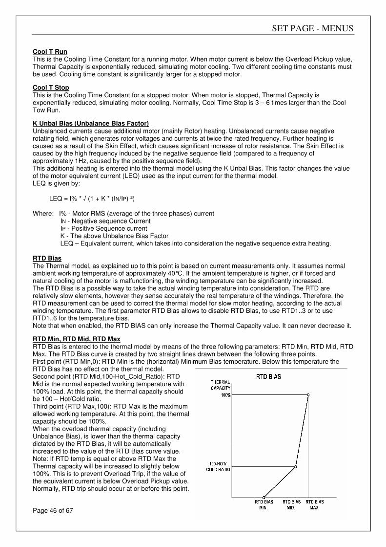
SET PAGE - MENUS
Page 46 of 67
Cool T Run This is the Cooling Time Constant for a running motor. When motor current is below the Overload Pickup value, Thermal Capacity is exponentially reduced, simulating motor cooling. Two different cooling time constants must be used. Cooling time constant is significantly larger for a stopped motor.
Cool T Stop This is the Cooling Time Constant for a stopped motor. When motor is stopped, Thermal Capacity is exponentially reduced, simulating motor cooling. Normally, Cool Time Stop is 3 – 6 times larger than the Cool Tow Run.
K Unbal Bias (Unbalance Bias Factor) Unbalanced currents cause additional motor (mainly Rotor) heating. Unbalanced currents cause negative rotating field, which generates rotor voltages and currents at twice the rated frequency. Further heating is caused as a result of the Skin Effect, which causes significant increase of rotor resistance. The Skin Effect is caused by the high frequency induced by the negative sequence field (compared to a frequency of approximately 1Hz, caused by the positive sequence field). This additional heating is entered into the thermal model using the K Unbal Bias. This factor changes the value of the motor equivalent current (LEQ) used as the input current for the thermal model. LEQ is given by:
LEQ = I% * √ (1 + K * (IN/IP) ²) Where: I% - Motor RMS (average of the three phases) current
IN - Negative sequence Current IP - Positive Sequence current K - The above Unbalance Bias Factor LEQ – Equivalent current, which takes into consideration the negative sequence extra heating.
RTD Bias The Thermal model, as explained up to this point is based on current measurements only. It assumes normal ambient working temperature of approximately 40°C. If the ambient temperature is higher, or if forced and natural cooling of the motor is malfunctioning, the winding temperature can be significantly increased. The RTD Bias is a possible way to take the actual winding temperature into consideration. The RTD are relatively slow elements, however they sense accurately the real temperature of the windings. Therefore, the RTD measurement can be used to correct the thermal model for slow motor heating, according to the actual winding temperature. The first parameter RTD Bias allows to disable RTD Bias, to use RTD1..3 or to use RTD1..6 for the temperature bias. Note that when enabled, the RTD BIAS can only increase the Thermal Capacity value. It can never decrease it.
RTD Min, RTD Mid, RTD Max RTD Bias is entered to the thermal model by means of the three following parameters: RTD Min, RTD Mid, RTD Max. The RTD Bias curve is created by two straight lines drawn between the following three points. First point (RTD Min,0): RTD Min is the (horizontal) Minimum Bias temperature. Below this temperature the RTD Bias has no effect on the thermal model. Second point (RTD Mid,100-Hot_Cold_Ratio): RTD Mid is the normal expected working temperature with 100% load. At this point, the thermal capacity should be 100 – Hot/Cold ratio. Third point (RTD Max,100): RTD Max is the maximum allowed working temperature. At this point, the thermal capacity should be 100%. When the overload thermal capacity (including Unbalance Bias), is lower than the thermal capacity dictated by the RTD Bias, it will be automatically increased to the value of the RTD Bias curve value. Note: If RTD temp is equal or above RTD Max the Thermal capacity will be increased to slightly below 100%. This is to prevent Overload Trip, if the value of the equivalent current is below Overload Pickup value. Normally, RTD trip should occur at or before this point.
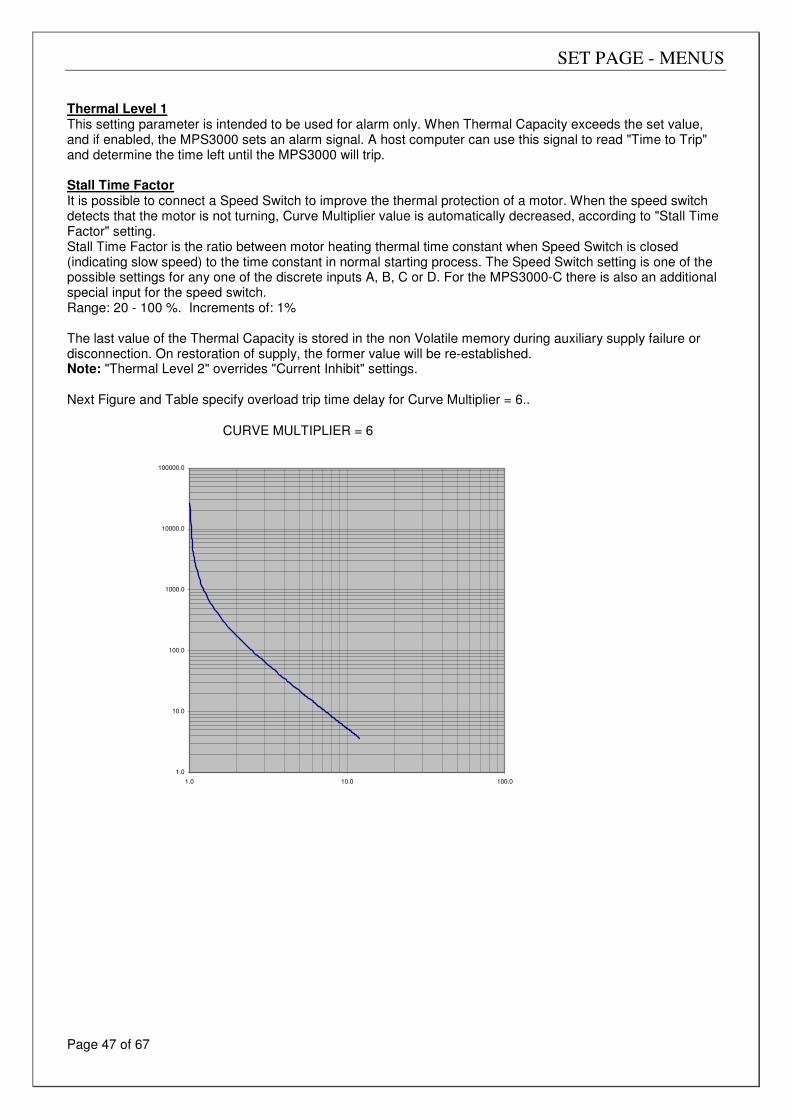
SET PAGE - MENUS
Page 47 of 67
Thermal Level 1 This setting parameter is intended to be used for alarm only. When Thermal Capacity exceeds the set value, and if enabled, the MPS3000 sets an alarm signal. A host computer can use this signal to read "Time to Trip" and determine the time left until the MPS3000 will trip. Stall Time Factor It is possible to connect a Speed Switch to improve the thermal protection of a motor. When the speed switch detects that the motor is not turning, Curve Multiplier value is automatically decreased, according to "Stall Time Factor" setting. Stall Time Factor is the ratio between motor heating thermal time constant when Speed Switch is closed (indicating slow speed) to the time constant in normal starting process. The Speed Switch setting is one of the possible settings for any one of the discrete inputs A, B, C or D. For the MPS3000-C there is also an additional special input for the speed switch. Range: 20 - 100 %. Increments of: 1% The last value of the Thermal Capacity is stored in the non Volatile memory during auxiliary supply failure or disconnection. On restoration of supply, the former value will be re-established. Note: "Thermal Level 2" overrides "Current Inhibit" settings. Next Figure and Table specify overload trip time delay for Curve Multiplier = 6..
CURVE MULTIPLIER = 6
1.0
10.0
100.0
1000.0
10000.0
100000.0
1.0 10.0 100.0
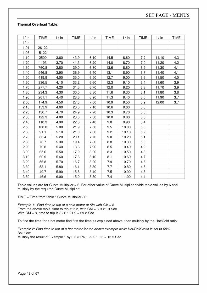
SET PAGE - MENUS
Page 48 of 67
Thermal Overload Table:
I / In TIME I / In TIME I / In TIME I / In TIME I / In TIME
I / In
1.01 26122
1.05 5122
1.10 2500 3.60 43.9 6.10 14.5 8.60 7.2 11.10 4.3
1.20 1193 3.70 41.3 6.20 14.0 8.70 7.0 11.20 4.2
1.30 760.8 3.80 39.0 6.30 13.6 8.80 6.9 11.30 4.1
1.40 546.8 3.90 36.9 6.40 13.1 8.90 6.7 11.40 4.1
1.50 419.9 4.00 35.0 6.50 12.7 9.00 6.6 11.50 4.0
1.60 336.5 4.10 33.2 6.60 12.3 9.10 6.4 11.60 3.9
1.70 277.7 4.20 31.5 6.70 12.0 9.20 6.3 11.70 3.9
1.80 234.3 4.30 30.0 6.80 11.6 9.30 6.1 11.80 3.8
1.90 201.1 4.40 28.6 6.90 11.3 9.40 6.0 11.90 3.7
2.00 174.9 4.50 27.3 7.00 10.9 9.50 5.9 12.00 3.7
2.10 153.9 4.60 26.0 7.10 10.6 9.60 5.8
2.20 136.7 4.70 24.9 7.20 10.3 9.70 5.6
2.30 122.3 4.80 23.8 7.30 10.0 9.80 5.5
2.40 110.3 4.90 22.8 7.40 9.8 9.90 5.4
2.50 100.0 5.00 21.9 7.50 9.5 10.00 5.3
2.60 91.1 5.10 21.0 7.60 9.2 10.10 5.2
2.70 83.4 5.20 20.1 7.70 9.0 10.20 5.1
2.80 76.7 5.30 19.4 7.80 8.8 10.30 5.0
2.90 70.8 5.40 18.6 7.90 8.5 10.40 4.9
3.00 65.6 5.50 17.9 8.00 8.3 10.50 4.8
3.10 60.9 5.60 17.3 8.10 8.1 10.60 4.7
3.20 56.8 5.70 16.7 8.20 7.9 10.70 4.6
3.30 53.1 5.80 16.1 8.30 7.7 10.80 4.5
3.40 49.7 5.90 15.5 8.40 7.5 10.90 4.5
3.50 46.6 6.00 15.0 8.50 7.4 11.00 4.4 Table values are for Curve Multiplier = 6. For other value of Curve Multiplier divide table values by 6 and multiply by the required Curve Multiplier: TIME = Time from table * Curve Multiplier / 6. Example 1: Find time to trip of a cold motor at 5In with CM = 8 From the above table, time to trip at 5In, with CM = 6 is 21.9 Sec. With CM = 8, time to trip is 8 / 6 * 21.9 = 29.2 Sec. To find the time for a hot motor find first the time as explained above, then multiply by the Hot/Cold ratio. Example 2: Find time to trip of a hot motor for the above example while Hot/Cold ratio is set to 60%. Solution: Multiply the result of Example 1 by 0.6 (60%). 29.2 * 0.6 = 15.5 Sec.
SET PAGE - MENUS
Page 49 of 67
Thermal Capacity Reset Method It is not possible to reset (to empty) the thermal capacity. Reset, of "Thermal Level 2", is prevented until "Thermal Capacity "cools down" bellow 50%. Therefore, even for a “Key Holder” reset of Thermal Level 2 trip is not possible for a cooling down period of time. Emergency Restart If one of the Discrete inputs A,B,C or D is configured as an Emergency Restart input and if this input (Emergency Restart Switch) is closed, then the Thermal Capacity automatically resets to 0 every time the motor is stopped. It is done to allow immediate restarting even if motor is hot. Closing the Emergency Restart switch while motor is already stopped causes also an immediate reset of the thermal capacity. As long as motor is running, the Emergency Restart switch has no effect. Therefore the MPS3000 can still trip for Thermal Level 2 even if the Emergency Restart switch is closed. Note: If an Emergency Restart input is used, RTD Bias should be set to OFF to ensure resetting of the Thermal capacity while motor is stopped. Warning: Use only for emergency case. Open switch immediately after Emergency is ended.
Unbalance Level 1 (Unbalance Level 1) Current unbalance is the Ratio between motor’s Negative Sequence current to its Positive Sequence current. Unbalance = IN / IP (Limited to: Unbalance <= 100%) If Motor average RMS current is less than the rated Motor FLC, then the Unbalance value is decreased by the factor Iavg / FLC, where Iavg is the RMS average of the three phase currents. Unbalance = (IN / IP) * (Iavg / FLC) This method prevents nuisance alarming at low currents. The MPS3000 initiates an alarm, UNBALANCE MIN T seconds after the actual unbalance value increases above 50% of Unbalance Level 2 setting. Auto reset, when Enabled, occurs when the actual unbalance decreases to below 50% of "Unbalance Level 2" setting, or when motor stops or trips.
Unbalance Level 2 (Unbalance Level 2) Unbalance Level 2 setting, determines the minimum value of actual unbalance for Unbalance level 2 fault. If the actual unbalance exceeds Unbalance Level 2 setting, a time delay is initiated. The time delay is related to Unbal. Max. Time parameter, and to the inverse of the square of the actual unbalance (smaller delay for larger unbalance). Minimum value of the time delay is UNBALANCE MIN T seconds. Auto reset, when enabled, occurs when the actual unbalance decreases to below Unbal. Level 2 setting, or when motor stops or trips. See next figure to select the required trip time for any unbalance value.
Note: Mains phase sequence (positive or negative) is used while calculating positive and negative sequence currents. Mains phase sequence is determined, using to the mains (three phase) voltages. If the MAINS (all three phases) is not connected to the MPS3000, positive MAINS sequence is assumed. If currents negative sequence is present, Unbalance Trip (if enabled) as well as wrong K factor (Unbalance Bias for Thermal Overload) influence is expected.
SET PAGE - MENUS
Page 50 of 67
Unbalance Protection Notes: 1. Select the required trip/alarm time on the vertical axis (at 10% unbalance).
2. Draw an horizontal line at the selected point (for example, 5 Sec.). 3. Select an unbalance point (for example 40%). 4. Draw a vertical line at the selected point (the two lines intersect). 5. Draw a parallel line to the diagonal lines at the intersection point. 6. Insert the value of the time at the intersection point (from 5) into parameter U/B LEVEL 2 MAX T
(for example 80 sec).
Undervoltage Active only after the start signal. Fault occurs when the average of the three line to line voltages decreases below "U/V Level", for more than "U/V Delay" setting. It is possible to connect single phase voltage to the line voltage inputs (terminals 78, 79, 80) and link them together (see page 6 - Line Voltage). Auto reset, when ENABLED, occurs when average line voltage increases above the U/V Setting value, or when motor trips. Note: If U/V fault is required even when motor is stopped, option 1 (U/V active in stop condition) should be ordered. MPS3000-P detects Start / Run / Stop conditions according to the level of current. If, during normal operation (mains is connected and motor is running), mains is disconnected and under voltage fault is required use option 1.
Over Voltage Level 1 (O/V Level 1) This is active only after the start signal. Fault occurs when the average of three line to line voltages increases above "O/V Level 1" setting, for more than 1 second. Auto reset, when Enabled, occurs when average line voltage decreases below "O/V Level 1" value, or when the motor trips.
Over Voltage Level 2 This is active only after the start signal. Fault occurs when the average line to line voltage increases above "Overvoltage Level 2" setting, for more than "O/V Level 2 Delay" setting. Auto reset, when Enabled, occurs when average line voltage decreases to below O/V Level 2 value, or when the motor trips.
Phase Loss The MPS3000 calculates voltage unbalance according to the difference between maximum and minimum values of the line to line voltages, related to the "Line Volts" setting. Fault occurs when the unbalance level exceeds 20% for more than 2 seconds Auto reset, when enabled, occurs when the actual Unbalance decreases below 20%. Note: Set Trip and Alarm to DISABLE, if three phase voltage is not measured.
Phase Sequence Always Active. Fault occurs when the phase sequence is reversed for more than 2 seconds. Disable Phase Sequence both for Trip and for Alarm, if only a single phase is connected to the voltage input terminals. Auto reset, when Enabled, occurs when a correct phase sequence is detected. Note: Set Trip and Alarm to DISABLE, if three phase voltage is not measured.
Ground Fault Level 1 (GND Fault Level 1) Fault occurs when Ground current exceeds "GND Fault Level 1" setting for more than the "G/F Level 1 Delay" setting. Auto reset, when Enabled, occurs when Ground current decreases below "GND Fault Level 1" setting. While starting, G/F During Start setting parameter overrides G/F Level 1. Designed to eliminate nuisance alarming during start process (with high currents) when residual "C/T" connection is used.
SET PAGE - MENUS
Page 51 of 67
Ground Fault Level 2 (GND Fault Level 2) Fault occurs when Ground current exceeds "GND Fault Level 2" setting for more than "G/F Level 2 Delay" setting. Minimum setting of "G/F Level 2 Delay" is 0. At 0 setting, the actual time delay is less than 70 ms. Auto reset, when Enabled, occurs when Ground current decreases below "GND Fault Level 2" setting. While starting, G/F During Start setting parameter overrides G/F Level 2. Designed to eliminate nuisance tripping during start process (with high currents) when residual "C/T" connection is used. Note: GND Fault Level 2 fault is prevented when the highest of any of the line currents Exceeds "Current Inhibit" value. It is designed to prevent opening of motor contactor under high short circuit conditions, to protect its contacts from being damaged.
Communication Port Failed (Comm. Port Failed) Fault occurs when the MPS3000 detects three consecutive transmissions from the host computer, in which a parity bit, and/or the CRC word are wrong. Auto reset, when Enabled, occurs when a transmission from the host computer is received properly.
Internal Failure The MPS3000 incorporates a Built In Test program. Operating the self test program is done from a special "Test/Maintenance Options" page. "Self Test Passed" message, after completion of the built in test, indicates that the MPS3000 functions properly. "Self Test Failed", together with an error code (for factory use only) and Internal Fault Led "ON" indicates a fault condition. Auto reset, when Enabled, occurs when a successful test was performed and its result is "Self Test Passed" message. Note: Most of the MPS3000 self test programs are running continuously (much slower then the main program) in the "background".
Control Circuit Open and Welded Contactor (Control Cir. Open), (Welded Contactor) The MPS3000-C determines if the motor contactors are open or closed by checking the position of their auxiliary contacts. Any change in the position of the internal relays A and B (controlling the contactors) is followed by checking their contacts position. Please note that the Control Open / Welded contactor protections for contactor A are operative only if Config. Input A and B are set to Contactor A N.C. and N.O. respectively. Same is correct for contactor B and Config. Input C and D. Control Circuit Open: Fault occurs, if a change in the contactor's auxiliary contacts is not recognized after energizing the internal relays A or B. Such a situation usually indicates, an "Control Circuit Open" fault.
Welded Contactor: Fault occurs, if a change in the contactor's auxiliary contacts is not recognized after de-energizing the internal relays A or B. Such a situation usually indicates a "Welded Contactor" fault. Auto reset, when Enabled, occurs when motor contactors properly follow the MPS3000-C commands. Note: If motor contactors auxiliary contacts are not connected to the MPS3000-C Inputs, both the alarm and trip of "Control Circuit Open" and "Welded Contactor" faults must be disabled. Note: When "Control Cir. Open" and "Welded Contactor" faults are disabled, "Hard-wired Start" and "Hard-Wired Stop" which receive information from the contactors auxiliary contacts are inoperative.
External Fault 1 / 2 / 3 External Fault 1, 2 or 3 occurs when the MPS3000 detects closed contact between the "External Fault 1", "External Fault 2" or "External Fault 3" input terminals respectively. These inputs can be used for any external faults.
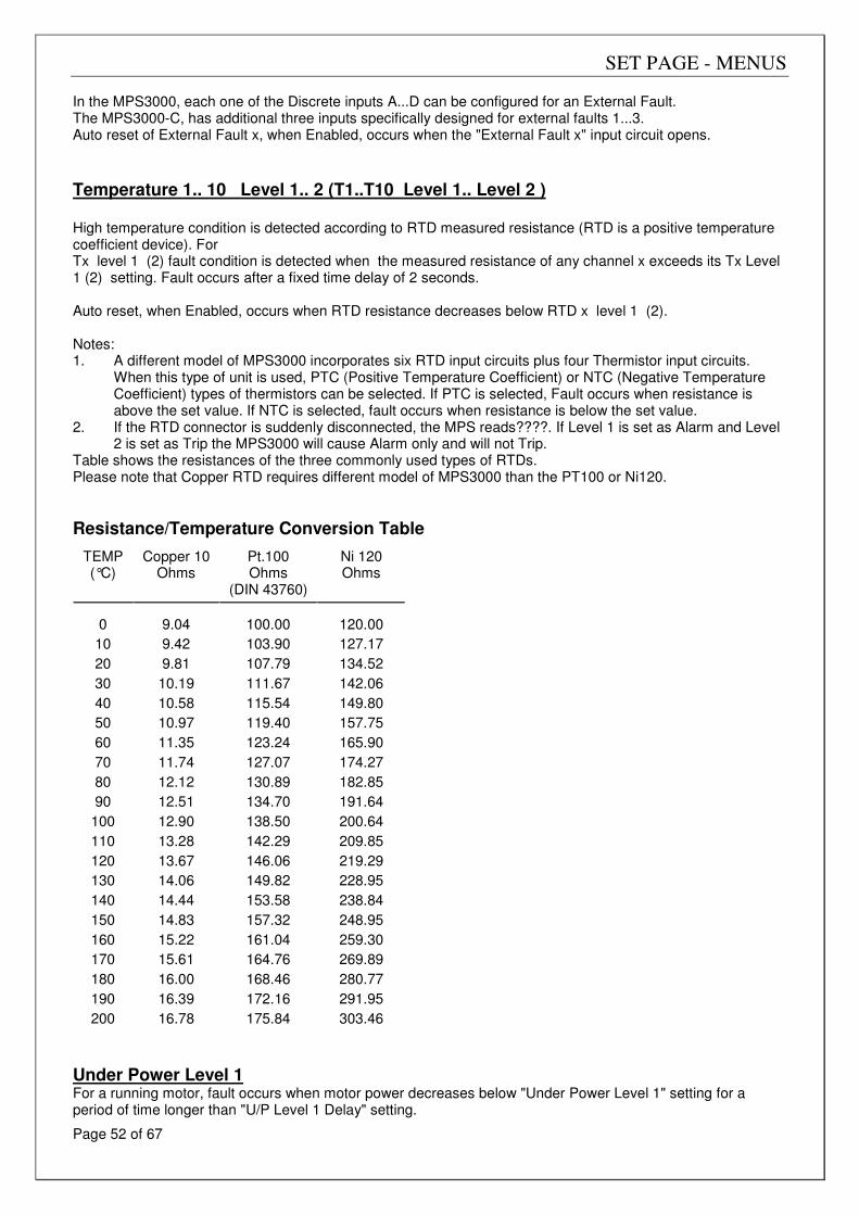
SET PAGE - MENUS
Page 52 of 67
In the MPS3000, each one of the Discrete inputs A...D can be configured for an External Fault. The MPS3000-C, has additional three inputs specifically designed for external faults 1...3. Auto reset of External Fault x, when Enabled, occurs when the "External Fault x" input circuit opens.
Temperature 1.. 10 Level 1.. 2 (T1..T10 Level 1.. Level 2 ) High temperature condition is detected according to RTD measured resistance (RTD is a positive temperature coefficient device). For Tx level 1 (2) fault condition is detected when the measured resistance of any channel x exceeds its Tx Level 1 (2) setting. Fault occurs after a fixed time delay of 2 seconds. Auto reset, when Enabled, occurs when RTD resistance decreases below RTD x level 1 (2). Notes: 1. A different model of MPS3000 incorporates six RTD input circuits plus four Thermistor input circuits.
When this type of unit is used, PTC (Positive Temperature Coefficient) or NTC (Negative Temperature Coefficient) types of thermistors can be selected. If PTC is selected, Fault occurs when resistance is above the set value. If NTC is selected, fault occurs when resistance is below the set value.
2. If the RTD connector is suddenly disconnected, the MPS reads????. If Level 1 is set as Alarm and Level 2 is set as Trip the MPS3000 will cause Alarm only and will not Trip.
Table shows the resistances of the three commonly used types of RTDs. Please note that Copper RTD requires different model of MPS3000 than the PT100 or Ni120.
Resistance/Temperature Conversion Table TEMP (°C)
Copper 10
Ohms
Pt.100 Ohms
(DIN 43760)
Ni 120 Ohms
0
9.04
100.00
120.00
10 9.42 103.90 127.17
20 9.81 107.79 134.52
30 10.19 111.67 142.06
40 10.58 115.54 149.80
50 10.97 119.40 157.75
60 11.35 123.24 165.90
70 11.74 127.07 174.27
80 12.12 130.89 182.85
90 12.51 134.70 191.64
100 12.90 138.50 200.64
110 13.28 142.29 209.85
120 13.67 146.06 219.29
130 14.06 149.82 228.95
140 14.44 153.58 238.84
150 14.83 157.32 248.95
160 15.22 161.04 259.30
170 15.61 164.76 269.89
180 16.00 168.46 280.77
190 16.39 172.16 291.95
200 16.78 175.84 303.46
Under Power Level 1 For a running motor, fault occurs when motor power decreases below "Under Power Level 1" setting for a period of time longer than "U/P Level 1 Delay" setting.
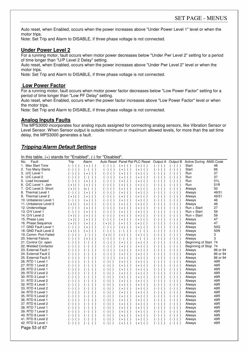
SET PAGE - MENUS
Page 53 of 67
Auto reset, when Enabled, occurs when the power increases above "Under Power Level 1" level or when the motor trips. Note: Set Trip and Alarm to DISABLE, if three phase voltage is not connected.
Under Power Level 2 For a running motor, fault occurs when motor power decreases below "Under Pwr Level 2" setting for a period of time longer than "U/P Level 2 Delay" setting. Auto reset, when Enabled, occurs when the power increases above "Under Pwr Level 2" level or when the motor trips. Note: Set Trip and Alarm to DISABLE, if three phase voltage is not connected.
Low Power Factor For a running motor, fault occurs when motor power factor decreases below "Low Power Factor" setting for a period of time longer than "Low PF Delay" setting. Auto reset, when Enabled, occurs when the power factor increases above "Low Power Factor" level or when the motor trips. Note: Set Trip and Alarm to DISABLE, if three phase voltage is not connected.
Analog Inputs Faults The MPS3000 incorporates four analog inputs assigned for connecting analog sensors, like Vibration Sensor or Level Sensor. When Sensor output is outside minimum or maximum allowed levels, for more than the set time delay, the MPS3000 generates a fault.
Tripping/Alarm Default Settings In this table, (+) stands for "Enabled", (-) for "Disabled". No. Fault Trip Alarm Auto Reset Panel Rst PLC Reset Output A Output B Active During ANSI Code 1. Max Start Time ( - ) ( ) ( + ) ( ) ( - ) ( ) ( + ) ( ) ( + ) ( ) ( - ) ( ) ( - ) ( ) Start 48 2. Too Many Starts ( - ) ( ) ( - ) ( ) ( - ) ( ) ( + ) ( ) ( + ) ( ) ( - ) ( ) ( - ) ( ) Start 66 3. U/C Level 1 ( - ) ( ) ( + ) ( ) ( - ) ( ) ( + ) ( ) ( + ) ( ) ( - ) ( ) ( - ) ( ) Run 37 4. U/C Level 2 ( - ) ( ) ( - ) ( ) ( - ) ( ) ( + ) ( ) ( + ) ( ) ( - ) ( ) ( - ) ( ) Run 37 5. Load Increased ( - ) ( ) ( + ) ( ) ( - ) ( ) ( + ) ( ) ( + ) ( ) ( - ) ( ) ( - ) ( ) Run 51L 6. O/C Level 1- Jam ( + ) ( ) ( + ) ( ) ( - ) ( ) ( + ) ( ) ( + ) ( ) ( - ) ( ) ( - ) ( ) Run 51R 7. O/C Level 2- Short ( + ) ( ) (+ ) ( ) ( - ) ( ) ( + ) ( ) ( + ) ( ) ( - ) ( ) ( - ) ( ) Always 50 8. Thermal Level 1 ( - ) ( ) ( + ) ( ) ( - ) ( ) ( + ) ( ) ( + ) ( ) ( - ) ( ) ( - ) ( ) Always 49/51 9. Thermal Level 2 ( + ) ( ) ( + ) ( ) ( - ) ( ) ( + ) ( ) ( + ) ( ) ( - ) ( ) ( - ) ( ) Always 49/51 10. Unbalance Level 1 ( - ) ( ) ( + ) ( ) ( - ) ( ) ( + ) ( ) ( + ) ( ) ( - ) ( ) ( - ) ( ) Always 46 11. Unbalance Level 2 ( + ) ( ) ( + ) ( ) ( - ) ( ) ( + ) ( ) ( + ) ( ) ( - ) ( ) ( - ) ( ) Always 46 12. Undervoltage ( - ) ( ) ( + ) ( ) ( - ) ( ) ( + ) ( ) ( + ) ( ) ( - ) ( ) ( - ) ( ) Run + Start 27 13. O/V Level 1 ( - ) ( ) ( + ) ( ) ( - ) ( ) ( + ) ( ) ( + ) ( ) ( - ) ( ) ( - ) ( ) Run + Start 59 14. O/V Level 2 ( + ) ( ) ( + ) ( ) ( - ) ( ) ( + ) ( ) ( + ) ( ) ( - ) ( ) ( - ) ( ) Run + Start 59 15. Phase Loss ( + ) ( ) ( + ) ( ) ( - ) ( ) ( + ) ( ) ( + ) ( ) ( - ) ( ) ( - ) ( ) Always 47 16. Phase Sequence ( + ) ( ) ( + ) ( ) ( + ) ( ) ( + ) ( ) ( + ) ( ) ( - ) ( ) ( - ) ( ) Always 47 17. GND Fault Level 1 ( - ) ( ) ( + ) ( ) ( - ) ( ) ( + ) ( ) ( + ) ( ) ( - ) ( ) ( - ) ( ) Always 50G 18. GND Fault Level 2 ( + ) ( ) ( + ) ( ) ( - ) ( ) ( - ) ( ) ( - ) ( ) ( - ) ( ) ( - ) ( ) Always 50N 19. Comm. Port Failed ( - ) ( ) ( - ) ( ) ( + ) ( ) ( + ) ( ) ( + ) ( ) ( - ) ( ) ( - ) ( ) Always 3 20. Internal Failure ( - ) ( ) ( + ) ( ) ( - ) ( ) ( - ) ( ) ( - ) ( ) ( - ) ( ) ( - ) ( ) Always 3 21. Control Cir. open ( - ) ( ) ( - ) ( ) ( - ) ( ) ( + ) ( ) ( + ) ( ) ( - ) ( ) ( - ) ( ) Beginning of Start 74 22. Welded Contactor ( - ) ( ) ( - ) ( ) ( - ) ( ) ( + ) ( ) ( + ) ( ) ( - ) ( ) ( - ) ( ) Beginning of Stop 74 23. External Fault 1 ( - ) ( ) ( - ) ( ) ( - ) ( ) ( + ) ( ) ( + ) ( ) ( - ) ( ) ( - ) ( ) Always 86 or 94 24. External Fault 2 ( - ) ( ) ( - ) ( ) ( - ) ( ) ( + ) ( ) ( + ) ( ) ( - ) ( ) ( - ) ( ) Always 86 or 94 25. External Fault 3 ( - ) ( ) ( - ) ( ) ( - ) ( ) ( + ) ( ) ( + ) ( ) ( - ) ( ) ( - ) ( ) Always 86 or 94 26. RTD 1 Level 1 ( - ) ( ) ( - ) ( ) ( - ) ( ) ( + ) ( ) ( + ) ( ) ( - ) ( ) ( - ) ( ) Always 49R 27. RTD 1 Level 2 ( - ) ( ) ( - ) ( ) ( - ) ( ) ( + ) ( ) ( + ) ( ) ( - ) ( ) ( - ) ( ) Always 49R 28. RTD 2 Level 1 ( - ) ( ) ( - ) ( ) ( - ) ( ) ( + ) ( ) ( + ) ( ) ( - ) ( ) ( - ) ( ) Always 49R 29. RTD 2 Level 2 ( - ) ( ) ( - ) ( ) ( - ) ( ) ( + ) ( ) ( + ) ( ) ( - ) ( ) ( - ) ( ) Always 49R 30. RTD 3 Level 1 ( - ) ( ) ( - ) ( ) ( - ) ( ) ( + ) ( ) ( + ) ( ) ( - ) ( ) ( - ) ( ) Always 49R 31. RTD 3 Level 2 ( - ) ( ) ( - ) ( ) ( - ) ( ) ( + ) ( ) ( + ) ( ) ( - ) ( ) ( - ) ( ) Always 49R 32. RTD 4 Level 1 ( - ) ( ) ( - ) ( ) ( - ) ( ) ( + ) ( ) ( + ) ( ) ( - ) ( ) ( - ) ( ) Always 49R 33. RTD 4 Level 2 ( - ) ( ) ( - ) ( ) ( - ) ( ) ( + ) ( ) ( + ) ( ) ( - ) ( ) ( - ) ( ) Always 49R 34. RTD 5 Level 1 ( - ) ( ) ( - ) ( ) ( - ) ( ) ( + ) ( ) ( + ) ( ) ( - ) ( ) ( - ) ( ) Always 49R 35. RTD 5 Level 2 ( - ) ( ) ( - ) ( ) ( - ) ( ) ( + ) ( ) ( + ) ( ) ( - ) ( ) ( - ) ( ) Always 49R 36. RTD 6 Level 1 ( - ) ( ) ( - ) ( ) ( - ) ( ) ( + ) ( ) ( + ) ( ) ( - ) ( ) ( - ) ( ) Always 49R 37. RTD 6 Level 2 ( - ) ( ) ( - ) ( ) ( - ) ( ) ( + ) ( ) ( + ) ( ) ( - ) ( ) ( - ) ( ) Always 49R 38. RTD 7 Level 1 ( - ) ( ) ( - ) ( ) ( - ) ( ) ( + ) ( ) ( + ) ( ) ( - ) ( ) ( - ) ( ) Always 49R 39. RTD 7 Level 2 ( - ) ( ) ( - ) ( ) ( - ) ( ) ( + ) ( ) ( + ) ( ) ( - ) ( ) ( - ) ( ) Always 49R 40. RTD 8 Level 1 ( - ) ( ) ( - ) ( ) ( - ) ( ) ( + ) ( ) ( + ) ( ) ( - ) ( ) ( - ) ( ) Always 49R 41. RTD 8 Level 2 ( - ) ( ) ( - ) ( ) ( - ) ( ) ( + ) ( ) ( + ) ( ) ( - ) ( ) ( - ) ( ) Always 49R 42. RTD 9 Level 1 ( - ) ( ) ( - ) ( ) ( - ) ( ) ( + ) ( ) ( + ) ( ) ( - ) ( ) ( - ) ( ) Always 49R
SET PAGE - MENUS
Page 54 of 67
43. RTD 9 Level 2 ( - ) ( ) ( - ) ( ) ( - ) ( ) ( + ) ( ) ( + ) ( ) ( - ) ( ) ( - ) ( ) Always 49R 44. RTD 10 Level 1 ( - ) ( ) ( - ) ( ) ( - ) ( ) ( + ) ( ) ( + ) ( ) ( - ) ( ) ( - ) ( ) Always 49R 45. RTD 10 Level 2 ( - ) ( ) ( - ) ( ) ( - ) ( ) ( + ) ( ) ( + ) ( ) ( - ) ( ) ( - ) ( ) Always 49R 46. Under Pwr Level 1 ( - ) ( ) ( - ) ( ) ( - ) ( ) ( + ) ( ) ( + ) ( ) ( - ) ( ) ( - ) ( ) Run 32L 47. Under Pwr Level 2 ( - ) ( ) ( - ) ( ) ( - ) ( ) ( + ) ( ) ( + ) ( ) ( - ) ( ) ( - ) ( ) Run 32L 48. Low Power Factor ( - ) ( ) ( - ) ( ) ( - ) ( ) ( + ) ( ) ( + ) ( ) ( - ) ( ) ( - ) ( ) Run 55 49. Analog Input # 1 ( - ) ( ) ( - ) ( ) ( - ) ( ) ( + ) ( ) ( + ) ( ) ( - ) ( ) ( - ) ( ) Always ?? 50. Analog Input # 2 ( - ) ( ) ( - ) ( ) ( - ) ( ) ( + ) ( ) ( + ) ( ) ( - ) ( ) ( - ) ( ) Always ?? 51. Analog Input # 3 ( - ) ( ) ( - ) ( ) ( - ) ( ) ( + ) ( ) ( + ) ( ) ( - ) ( ) ( - ) ( ) Always ?? 52. Analog Input # 4 ( - ) ( ) ( - ) ( ) ( - ) ( ) ( + ) ( ) ( + ) ( ) ( - ) ( ) ( - ) ( ) Always ??
Added options available in the MPS3000 which correspond to ANSI codes Speed Switch Input (No Rotation detector) 14 Lock-Out on thermal Trip 86 RTD Bias for Thermal Overload ?? Unbalance Bias for Thermal Overload ?? Low Speed switch of Two-Speed motor ?? Emergency switch effect on Thermal Overload (reset of thermal capacity when stopped) ?? Emergency switch effect on Too Many Starts (not recording starts while in emergency) ?? Fault Simulation (of Voltages, currents, temperature)
??
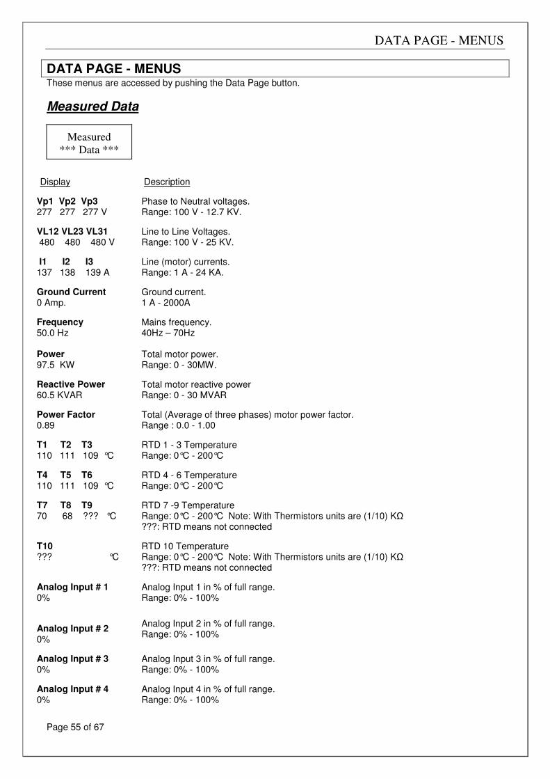
DATA PAGE - MENUS
Page 55 of 67
DATA PAGE - MENUS These menus are accessed by pushing the Data Page button.
Measured Data
Measured
*** Data ***
Display Description
Vp1 Vp2 Vp3 277 277 277 V
Phase to Neutral voltages. Range: 100 V - 12.7 KV.
VL12 VL23 VL31 480 480 480 V
Line to Line Voltages. Range: 100 V - 25 KV.
I1 I2 I3 137 138 139 A
Line (motor) currents. Range: 1 A - 24 KA.
Ground Current 0 Amp.
Ground current. 1 A - 2000A
Frequency 50.0 Hz Power 97.5 KW
Mains frequency. 40Hz – 70Hz Total motor power. Range: 0 - 30MW.
Reactive Power 60.5 KVAR
Total motor reactive power Range: 0 - 30 MVAR
Power Factor 0.89
Total (Average of three phases) motor power factor. Range : 0.0 - 1.00
T1 T2 T3 110 111 109 °C
RTD 1 - 3 Temperature Range: 0°C - 200°C
T4 T5 T6 110 111 109 °C
RTD 4 - 6 Temperature Range: 0°C - 200°C
T7 T8 T9 70 68 ??? °C
RTD 7 -9 Temperature Range: 0°C - 200°C Note: With Thermistors units are (1/10) KΩ ???: RTD means not connected
T10 ??? °C
RTD 10 Temperature Range: 0°C - 200°C Note: With Thermistors units are (1/10) KΩ ???: RTD means not connected
Analog Input # 1 0%
Analog Input 1 in % of full range. Range: 0% - 100%
Analog Input # 2 0%
Analog Input 2 in % of full range. Range: 0% - 100%
Analog Input # 3 0%
Analog Input 3 in % of full range. Range: 0% - 100%
Analog Input # 4 0%
Analog Input 4 in % of full range. Range: 0% - 100%
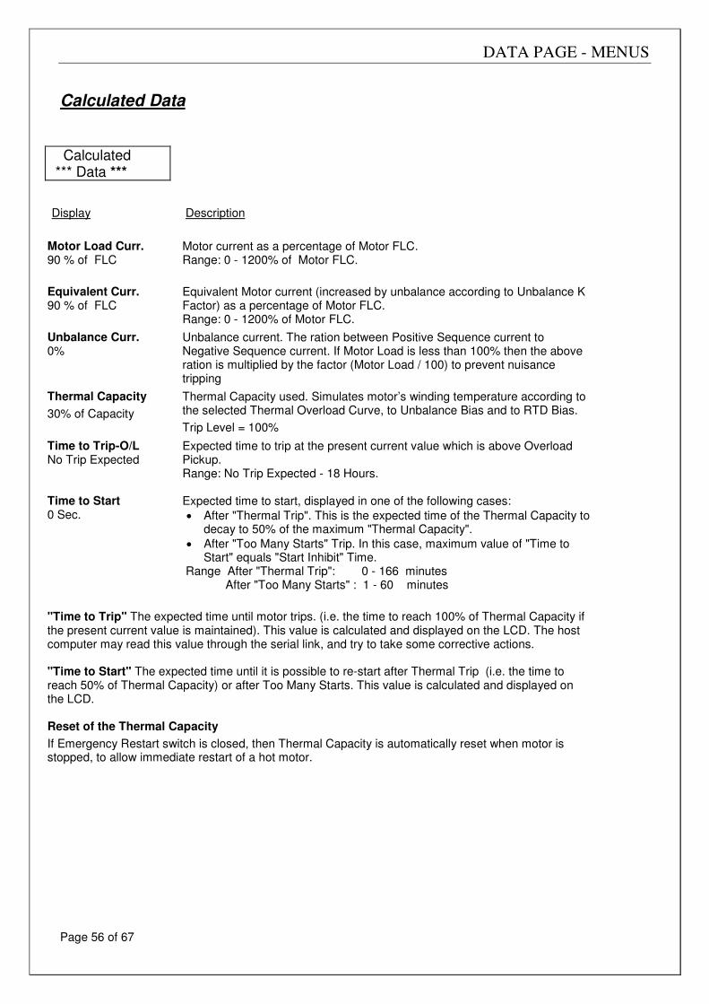
DATA PAGE - MENUS
Page 56 of 67
Calculated Data
Calculated *** Data ***
Display
Description
Motor Load Curr. 90 % of FLC
Motor current as a percentage of Motor FLC. Range: 0 - 1200% of Motor FLC.
Equivalent Curr. 90 % of FLC
Equivalent Motor current (increased by unbalance according to Unbalance K Factor) as a percentage of Motor FLC. Range: 0 - 1200% of Motor FLC.
Unbalance Curr. 0%
Unbalance current. The ration between Positive Sequence current to Negative Sequence current. If Motor Load is less than 100% then the above ration is multiplied by the factor (Motor Load / 100) to prevent nuisance tripping
Thermal Capacity
30% of Capacity
Thermal Capacity used. Simulates motor’s winding temperature according to the selected Thermal Overload Curve, to Unbalance Bias and to RTD Bias.
Trip Level = 100%
Time to Trip-O/L No Trip Expected Time to Start 0 Sec.
Expected time to trip at the present current value which is above Overload Pickup. Range: No Trip Expected - 18 Hours. Expected time to start, displayed in one of the following cases:
• After "Thermal Trip". This is the expected time of the Thermal Capacity to decay to 50% of the maximum "Thermal Capacity".
• After "Too Many Starts" Trip. In this case, maximum value of "Time to Start" equals "Start Inhibit" Time.
Range After "Thermal Trip": 0 - 166 minutes After "Too Many Starts" : 1 - 60 minutes
"Time to Trip" The expected time until motor trips. (i.e. the time to reach 100% of Thermal Capacity if the present current value is maintained). This value is calculated and displayed on the LCD. The host computer may read this value through the serial link, and try to take some corrective actions. "Time to Start" The expected time until it is possible to re-start after Thermal Trip (i.e. the time to reach 50% of Thermal Capacity) or after Too Many Starts. This value is calculated and displayed on the LCD. Reset of the Thermal Capacity
If Emergency Restart switch is closed, then Thermal Capacity is automatically reset when motor is stopped, to allow immediate restart of a hot motor.
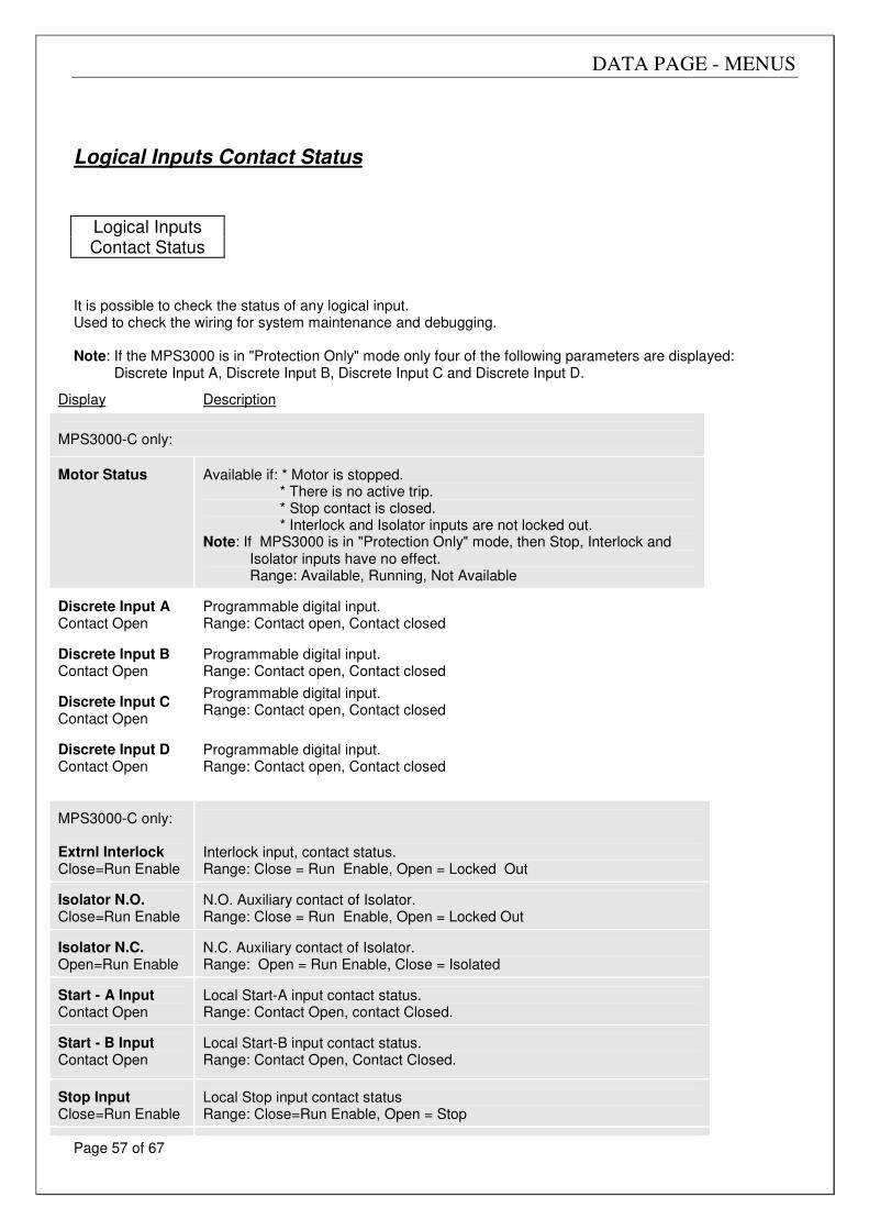
DATA PAGE - MENUS
Page 57 of 67
Logical Inputs Contact Status
It is possible to check the status of any logical input. Used to check the wiring for system maintenance and debugging. Note: If the MPS3000 is in "Protection Only" mode only four of the following parameters are displayed: Discrete Input A, Discrete Input B, Discrete Input C and Discrete Input D.
Display
Description
MPS3000-C only: Motor Status
Available if: * Motor is stopped.
* There is no active trip. * Stop contact is closed. * Interlock and Isolator inputs are not locked out.
Note: If MPS3000 is in "Protection Only" mode, then Stop, Interlock and Isolator inputs have no effect. Range: Available, Running, Not Available
Discrete Input A Contact Open
Programmable digital input. Range: Contact open, Contact closed
Discrete Input B Contact Open
Programmable digital input. Range: Contact open, Contact closed
Discrete Input C Contact Open
Programmable digital input. Range: Contact open, Contact closed
Discrete Input D Contact Open
Programmable digital input. Range: Contact open, Contact closed
MPS3000-C only: Extrnl Interlock Close=Run Enable
Interlock input, contact status. Range: Close = Run Enable, Open = Locked Out
Isolator N.O. Close=Run Enable
N.O. Auxiliary contact of Isolator. Range: Close = Run Enable, Open = Locked Out
Isolator N.C. Open=Run Enable
N.C. Auxiliary contact of Isolator. Range: Open = Run Enable, Close = Isolated
Start - A Input Contact Open
Local Start-A input contact status. Range: Contact Open, contact Closed.
Start - B Input Contact Open
Local Start-B input contact status. Range: Contact Open, Contact Closed.
Stop Input Close=Run Enable
Local Stop input contact status Range: Close=Run Enable, Open = Stop
Logical Inputs Contact Status
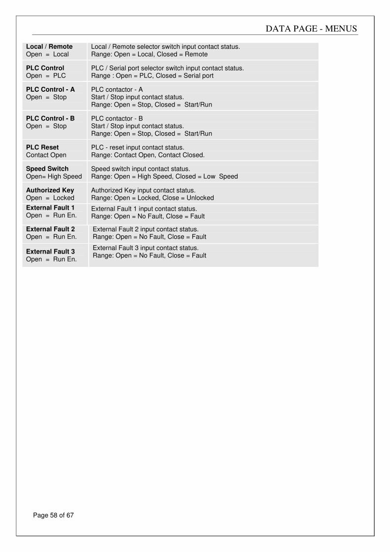
DATA PAGE - MENUS
Page 58 of 67
Local / Remote Open = Local
Local / Remote selector switch input contact status. Range: Open = Local, Closed = Remote
PLC Control Open = PLC
PLC / Serial port selector switch input contact status. Range : Open = PLC, Closed = Serial port
PLC Control - A Open = Stop
PLC contactor - A Start / Stop input contact status. Range: Open = Stop, Closed = Start/Run
PLC Control - B Open = Stop
PLC contactor - B Start / Stop input contact status. Range: Open = Stop, Closed = Start/Run
PLC Reset Contact Open
PLC - reset input contact status. Range: Contact Open, Contact Closed.
Speed Switch Open= High Speed
Speed switch input contact status. Range: Open = High Speed, Closed = Low Speed
Authorized Key Open = Locked
Authorized Key input contact status. Range: Open = Locked, Close = Unlocked
External Fault 1 Open = Run En.
External Fault 1 input contact status. Range: Open = No Fault, Close = Fault
External Fault 2 Open = Run En.
External Fault 2 input contact status. Range: Open = No Fault, Close = Fault
External Fault 3 Open = Run En.
External Fault 3 input contact status. Range: Open = No Fault, Close = Fault
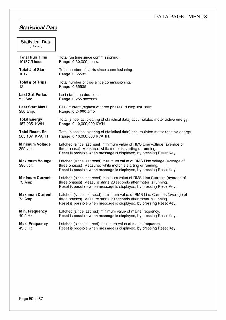
DATA PAGE - MENUS
Page 59 of 67
Statistical Data
Total Run Time 10137.5 hours
Total run time since commissioning. Range: 0-30,000 hours.
Total # of Start 1017
Total number of starts since commissioning. Range: 0-65535
Total # of Trips 12
Total number of trips since commissioning. Range: 0-65535
Last Strt Period 5.2 Sec.
Last start time duration. Range: 0-255 seconds.
Last Start Max I 350 amp.
Peak current (highest of three phases) during last start. Range: 0-24000 amp.
Total Energy 457,235 KWH
Total (since last clearing of statistical data) accumulated motor active energy. Range: 0-10,000,000 KWH.
Total React. En. 265,107 KVARH
Total (since last clearing of statistical data) accumulated motor reactive energy. Range: 0-10,000,000 KVARH.
Minimum Voltage 395 volt
Latched (since last reset) minimum value of RMS Line voltage (average of three phase). Measured while motor is starting or running. Reset is possible when message is displayed, by pressing Reset Key.
Maximum Voltage 395 volt
Latched (since last reset) maximum value of RMS Line voltage (average of three phases). Measured while motor is starting or running. Reset is possible when message is displayed, by pressing Reset Key.
Minimum Current 73 Amp.
Latched (since last reset) minimum value of RMS Line Currents (average of three phases), Measure starts 20 seconds after motor is running. Reset is possible when message is displayed, by pressing Reset Key.
Maximum Current 73 Amp.
Latched (since last reset) maximum value of RMS Line Currents (average of three phases), Measure starts 20 seconds after motor is running. Reset is possible when message is displayed, by pressing Reset Key.
Min. Frequency 49.9 Hz
Latched (since last rest) minimum value of mains frequency. Reset is possible when message is displayed, by pressing Reset Key.
Max. Frequency 49.9 Hz
Latched (since last rest) maximum value of mains frequency. Reset is possible when message is displayed, by pressing Reset Key.
Statistical Data - **** -
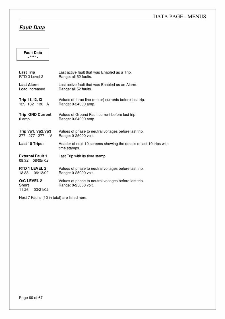
DATA PAGE - MENUS
Page 60 of 67
Fault Data
Fault Data
- **** -
Last Trip RTD 3 Level 2
Last active fault that was Enabled as a Trip. Range: all 52 faults.
Last Alarm Load Increased
Last active fault that was Enabled as an Alarm. Range: all 52 faults.
Trip I1, I2, I3 129 132 130 A
Values of three line (motor) currents before last trip. Range: 0-24000 amp.
Trip GND Current 0 amp.
Values of Ground Fault current before last trip. Range: 0-24000 amp.
Trip Vp1, Vp2,Vp3 277 277 277 V
Values of phase to neutral voltages before last trip. Range: 0-25000 volt.
Last 10 Trips:
Header of next 10 screens showing the details of last 10 trips with time stamps.
External Fault 1 08:32 08/05/ 02
Last Trip with its time stamp.
RTD 1 LEVEL 2 13:33 06/13/02
Values of phase to neutral voltages before last trip. Range: 0-25000 volt.
O/C LEVEL 2 - Short 11:26 03/21/02
Values of phase to neutral voltages before last trip. Range: 0-25000 volt.
Next 7 Faults (10 in total) are listed here.
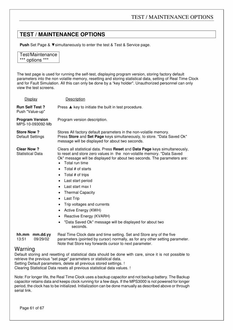
TEST / MAINTENANCE OPTIONS
Page 61 of 67
TEST / MAINTENANCE OPTIONS Push Set Page & simultaneously to enter the test & Test & Service page.
Test/Maintenance *** options ***
The test page is used for running the self-test, displaying program version, storing factory default parameters into the non volatile memory, resetting and storing statistical data, setting of Real Time Clock and for Fault Simulation. All this can only be done by a “key holder". Unauthorized personnel can only view the test screens.
Display
Description
Run Self Test ? Push "Value-up"
Press key to initiate the built in test procedure.
Program Version MPS-10-093092-Mb
Program version description.
Store Now ? Default Settings
Stores All factory default parameters in the non-volatile memory. Press Store and Set Page keys simultaneously, to store. "Data Saved Ok" message will be displayed for about two seconds.
Clear Now ? Statistical Data
Clears all statistical data. Press Reset and Data Page keys simultaneously, to reset and store zero values in the non-volatile memory. "Data Saved Ok" message will be displayed for about two seconds. The parameters are:
• Total run time
• Total # of starts
• Total # of trips
• Last start period
• Last start max I
• Thermal Capacity
• Last Trip
• Trip voltages and currents
• Active Energy (KWH)
• Reactive Energy (KVARH)
• "Data Saved Ok" message will be displayed for about two seconds.
hh.mm mm.dd.yy 13:51 09/29/02
Real Time Clock date and time setting. Set and Store any of the five parameters (pointed by cursor) normally, as for any other setting parameter. Note that Store key forwards cursor to next parameter.
Warning Default storing and resetting of statistical data should be done with care, since it is not possible to retrieve the previous "set page" parameters or statistical data. Setting Default parameters, delete all previous stored settings. ! Clearing Statistical Data resets all previous statistical data values. ! Note: For longer life, the Real Time Clock uses a backup capacitor and not backup battery. The Backup capacitor retains data and keeps clock running for a few days. If the MPS3000 is not powered for longer period, the clock has to be initialized. Initialization can be done manually as described above or through serial link.
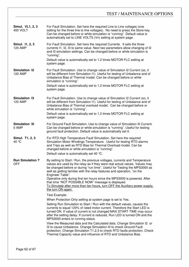
TEST / MAINTENANCE OPTIONS
Page 62 of 67
Simul. VL1, 2, 3 400 VOLT
For Fault Simulation. Set here the required Line to Line voltages (one setting for the three line to line voltages). No need to press the Store key. Can be changed before or while simulation is “running”. Default value is automatically set to LINE VOLTS (Vn) setting at system page.
Simul. I1, 2, 3 120 AMP
For Fault Simulation. Set here the required Currents. It sets the three currents I1, I2, I3 to same value. Next two parameters allow changing of I2 and I3 simulation settings. Can be changed before or while simulation is “running”.
Default value is automatically set to 1.2 times MOTOR FLC setting at system page.
Simulation I2 120 AMP
For Fault Simulation. Use to change value of Simulation I2 Current (so, it will be different from Simulation I1). Useful for testing of Unbalance and of Unbalance Bias of Thermal model. Can be changed before or while simulation is “running”.
Default value is automatically set to 1.2 times MOTOR FLC setting at system page.
Simulation I3 120 AMP
For Fault Simulation. Use to change value of Simulation I2 Current (so, it will be different from Simulation I1). Useful for testing of Unbalance and of Unbalance Bias of Thermal overload model. Can be changed before or while simulation is “running”.
Default value is automatically set to 1.2 times MOTOR FLC setting at system page.
Simulation I0 0 AMP
For Ground Fault Simulation. Use to change value of Simulation I0 Current. Can be changed before or while simulation is “running”. Useful for testing ground fault protection. Default value is automatically set 0.
Simul. T1, 2, 3 40 °C
For RTD High Temperature Fault Simulation. Set here the required Simulation Motor Windings Temperature. Useful for testing RTD alarms and Trips as well as RTD Bias for Thermal Overload model. Can be changed before or while simulation is “running”.
Default value is automatically set 40 °C. Run Simulation ? OFF
By setting to Start / Run, the previous voltages, currents and Temperature values are used by the relay as if they were real actual values. Values may be changed before or during “run time”. Useful for Testing the MPS3000 as well as getting familiar with the relay features and operation, “on the Engineer Table”. Operative only during first ten hours since the MPS3000 is powered. After that time “NOT POSSIBLE NOW” message is displayed. To Simulate after more than ten hours, turn OFF the Auxiliary power supply, the turn ON again.
Test Example:
When Protection Only setting at system page is set to Yes.
Setting Run Simulation to Start / Run with the default values, causes the currents to equal 120% of rated motor current. Therefore the Start LED is turned ON. If value of current is not changed MAX START TIME may occur after the setting delay. If current is reduced, Run LED is turned ON and the MPS3000 enters to running status.
View the Measured data and the Calculated data. Change Simulation I2 or I3 to cause Unbalance. Change Simulation I0 to check Ground Fault protection. Change Simulation T1,2,3 to check RTD faults protection. Check Thermal Capacity value and influence of RTD and Unbalance Bias.
TECHNICAL SPECIFICATIONSCOMMUNICATIONS – SERIAL LINK
Page 63 of 67
COMMUNICATIONS – SERIAL LINK The MPS3000 is equipped with a powerful data communication system, operating beyond a motor protection controller into the realm of a complete motor management system. This communication system is unmatched in its reliability, flexibility and ease of use providing the ideal basis for the design of a modern motor management system. The MPS3000 incorporates RS485 serial link and uses a MODBUS RTU protocol (The protocol is not included in this document) to provides high speed data acquisition to supervisory computers. Data formats have been carefully structured to provide fast notification of alarms and continuous updates of performance parameters. Load control can be performed from host computers or by PLCs. The following information and control can be accessed through the communication.
• All Actual data values
• All MPS3000 Parameter Settings (Read & Write)
• All the control commands for the MPS3000-C (such as Start A, Start B, Stop)
• Reset See MPS3000 Communication instruction manual. The MPS3000 system is user expandable. No special engineering skills or tools are required. For small systems, the Host computer can communicate directly with the MPS3000 via a twisted shielded pair. For larger systems a Data Highway enables multiple MPS3000 connection. Up to 32 MPS3000s can be added on each twisted pair of the Host serial link with full access to all MPS3000's. The system also performs high speed data acquisition Users therefore have a simple and friendly means of building a fully integrated monitoring and control systems. System reliability is exceptionally high, meeting the highest standards of reliable communication in the industry. Included in each message is a 16 bit CRC. Note: Protocols other than MODBUS RTU available upon consultation. Note: Terminate serial link cable with 120 Ohm resistors at both ends.
TECHNICAL SPECIFICATIONS
Page 64 of 67
TECHNICAL SPECIFICATIONS Auxiliary Power Supply
AC /DC Power Supply:
Standard voltage version: 85 - 250 V (for 110V or 220V AC or DC) Low voltage version: 19 - 60 V (for 24V or 48V AC or DC) Frequency: DC, 45 to 65 Hz. Power consumption: Less than 20 VA
Phase Current Inputs (three current) Method : True RMS, sample time 0.5 ms. Range: 0.05 to 12 * phase "C/T" Primary amps setting. Full scale: 12 * phase "C/T" Primary amps setting. Accuracy: ± 1.5% , for 0.9 to 1.5 * "C/T" Primary amps setting.
± 5% above 1.5 * "C/T" Primary ± (3% + 0.02 * "C/T" Primary) below 0.9 * "C/T" Primary
Power consumption: ≤ 0.1 VA per 1 A at 1 A. input, (Input impedance ≤ 100 mΩ) ≤ 1.0 VA per 5 A at 5 A. input, (Input impedance ≤ 20 mΩ)
Ground Fault Current Inputs (one current) Method : True RMS, sample time 0.5 ms. Range: 0.05 to 1.0 * G/F "C/T" Primary amps setting. Full scale: 1.0 * G/F "C/T" Primary amps setting. Accuracy: ± 3% of full scale. Power consumption: ≤ 0.1 VA per 1 A at 1 A. input, (Input impedance ≤ 100 mΩ)
≤ 0.5 VA per 5 A at 5 A. input, (Input impedance ≤ 20 mΩ)
Line Voltage Inputs (three voltages, with or without neutral) Method : True RMS, sample 0.5 ms. Power consumption: ≤ 0.2 VA Without VT transformer: Range: 50 - 750 volts. Full scale: 750 volts. Accuracy: ± 1.0% of full scale. With VT transformer: Range: 50 - 750 volts * (VT Primary / VT Secondary), limited to 25 KV. Full scale: 750 volts * (VT Primary / VT Secondary), limited to 25 KV. Accuracy: ± 1.0% of full scale.
Temperature Inputs (Ten RTDs - three wires or Six RTDs plus Four Thermistors) Time delay: 2 Sec. Range: Copper 10, PT100, Ni120: 0°C - 200°C PTC or NTC thermistor Model: 0 – 25.0 KΩ Accuracy: ± 3% of resistance. Max wire resistance: 25% of Sensor resistance at 10°C
Analog Inputs and Outputs: Range: 0 – 1mA or 0-20mA (different types). 0-20mA type can be set to 0-20mA or 4-20mA. Accuracy: 2% of Full Scale + 3% of input.
Overload Alarm and Trip Curves (both heating and cooling) Fault time accuracy: ± 1 second up to 10 seconds.
± 1 second +/- 2% above 10 seconds.
Threshold current level: Overload Pickup ± 1.5%. RTD Bias, Unbalance Bias.
TECHNICAL SPECIFICATIONS
Page 65 of 67
Total Run Time
Accuracy: ±2%.
Current Unbalance Alarm and Trip
Method: Unbalance = 100 * (Negative Sequence Current / Positive Sequence Current) [%] If Motor Load < 100% then multiply by * (Motor Load / 100)
This is to prevent nuisance tripping at low current levels. Level 1 Threshold Unbalance Level 1: 50% of Unbal Current setting ± 2%. Alarm (fixed) time delay: 1.0 ± 0.5 Sec. Level 2 Curves Threshold Unbalance Level 2: Unbal Current setting ± 2%. Trip time accuracy: ± 1 second up to 10 seconds. ± 1 second +/- 2% above 10 seconds.
Fault Time Delays
Accuracy: ±0.5 Sec. or ±2% of time, which ever is greater, for all but the above mentioned faults and the following exceptions: * Overcurrent Level 2: When adjusted to 0 >>> 60 ms +/- 20 ms. -0.1/+0.2 Sec. up to 1 Sec. * Ground fault trip: -0.1/+0.2 Sec. for less than 1 Sec. delay.
Relays Contacts
Rated load: 8A/250 VAC 1800VA. Maximum voltage: 250VAC.
Dielectric Strength
1500 VAC, for 1 minute, Between Ground (terminal 63) and: * Current inputs. * Auxiliary power supply inputs * Voltage inputs. * Control terminals
Power and Reactive Power Measurements
Method: True RMS over three phase voltages and currents. Range : 0.1 KW - 30MW (0.1 KVAR - 30 MVAR) Full Scale : 30MW (30 MVAR) Resolution : 0.1 KW below 1 MW, 0.01 MW above 1 MW. Accuracy : For V ≥ 90 * VT Primary / VT Secondary & Power factor ≥ 0.5, with three phase voltages. Two Ranges : 1. For (10% < I ≤ 150%) of "C/T" primary, accuracy is :
± (2% + 0.01 * "C/T" Primary/ Motor FLC.) of motor rated Power 2. For ( I ≥ 150%) of "C/T" primary, accuracy is :
± 7% of the display reading
Power Factor
Method: Ratio between total power (P) to total apparent power (VA). Range : 0.0 - 1.0 leading / lagging. Resolution : 0.001 Accuracy : For V ≥ 90 * VT Primary / VT Secondary & I ≥ 50% of "C/T" Primary & Power factor ≥ 0.7
it is ± 0.03
Ambient Temperature 0°C to +50°C
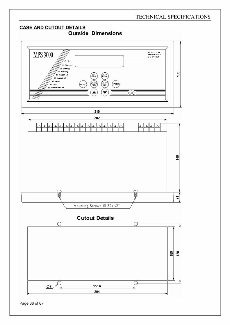
TECHNICAL SPECIFICATIONS
Page 66 of 67
CASE AND CUTOUT DETAILS
TECHNICAL SPECIFICATIONS
Page 67 of 67
Acronyms Description
V/Ta Voltage Transformer
C/T Current Transformer
DOL Direct online