Embed Size (px)
Citation preview

MPLS Mobile Backhaul Evolution – 4G LTE and Beyond
MR-305 Approval Date: 15 October 2012
Publication Date: 16 October 2012
Ambassador name Broadband Forum Ambassador/Title
Company

2
Agenda
1. Introduction to the Broadband Forum
2. Mobile Market Overview
3. Ethernet and IP VPN Backhaul Architecture
4. Timing and Synchronization
5. Quality of Service (QoS) Requirements
6. Resiliency, Protection and Performance
7. IPv6 Considerations
8. Energy Efficiency
9. Relationship to MEF 22.1
10. Deployment Examples
11. BBF Mobile Backhaul Work Plan – 2012
12. Summary

3
MPLS Mobile Backhaul Evolution Tutorial Contributors
Rao Cherukuri – Juniper Networks
Dave Christophe – Alcatel-Lucent
Bruno De Troch - Juniper Networks
Sharam Hakimi - EXFO
Richard Gough - Ericsson
Drew Rexrode – Verizon
Dave Sinicrope – Ericsson
Konstantinos Samdanis – NEC
Rami Yaron – DragonWave

Broadband Forum
Insert slides from current approved
Ambassador slide deck
4

Mobile Market Overview
Issues, trends and enablers of the
transition to IP/MPLS in evolving backhaul
architectures

6
State of the Market
Voice, text messages and data consumption drive majority of
current revenue
– Price competition
– Reduction or flattening of growth in
minutes per subscriber in markets
such as North America
– Subscribers granted ability to customize phones
LTE Deployments
– Significantly expand data capacity to enable new devices,
services and applications ARPU growth
– Initial LTE deployments focus on data services
– Focus on enhancing throughput and reducing cost per bit
– Increased services for more demanding applications and smart
devices
Declining average
revenue per user
(ARPU)

7
Requirement:
DL: 100 Mbps
UL: 50 Mbps
DL: 153 kbps
UL: 153 kbps DL: 2.4 Mbps
UL: 153 kbps
DL: 3.1 Mbps
UL: 1.8 Mbps
DL: 3.1-73 Mbps
UL: 1.8-27 Mbps
Evolution to LTE is all about Services
CDMA2000
1X EV-DO Rev A
EV-DO Rev B
CDMA2000
1xEV-DO
Broadband data VOD, MOD High-speed
Internet Enterprise
applications
Voice High-speed data
Picture/Video Email
Web browsing
Real-time apps Video
telephony, VoIP,PTx,
Interactive gaming,
Multimedia
Broadband Real-time
Applications
Multimedia,
VoIP, Video Delivery,
Advanced IMS
DL: 114 kbps
UL: 114 kbps DL: 384 kbps
UL: 384 kbps
DL: 1.8-7.2 Mbps
UL: 384Kbps
GSM
GPRS HSDPA
Rel 5
UMTS (W-CDMA)
R99
DL: 384 kbps
UL: 384 kbps
EDGE
DL: 7.2 Mbps
UL: 5.2 Mbps
HSUPA
Rel 6
Target:
DL: 40 Mbps
UL: 10 Mbps
LTE HSPA+
Rel 7 Phase 2
HSPA+
Rel 8 Phase 1
CDMA
WCDMA
Services
IP/Ethernet TDM (SONET/SDH, PDH) FR, HDLC, ATM/IMA
TRANSPORT
Requirement:
DL: 100 Mbps
UL: 50 Mbps
LTE
2001 2002 2003 2004 2005 2006 2007 2008 2009 2010 2011,12
Unified
IP Centric
Service
Delivery

8
LTE: All-IP, simplified network architecture
Evolved Packet Core = end-to-end IP transformation of mobile core
New, all-IP mobile core network introduced with LTE End-to-end IP
Clear delineation of control plane and data plane
Simplified architecture: flat-IP architecture with a single core
What is EPC ?
LTE+EPC
eNode B (eNB)
IP channel Evolved Packet Core (EPC)
IP Network
Transport (backhaul and backbone)
Broadband Forum focus areas for backhaul

Smart Mobile Devices: Diversity, Explosion
9
Source: IDC, 2012
9

10
Revenue by Technology
• Most cell sites will support multiple wireless technologies

Traffic Growth — Ethernet to the Rescue
• Costs of traffic drive operators to IP/Ethernet backhaul
– The “new Ethernet wireline” (Ethernet over fiber or copper, DSL, PON, cable) costs
significantly less per bit than TDM
• Capacities and charges reflect current planning for HSPA+ and LTE Source: Infonetics Research: Mobile Backhaul Equipment and Services, Market Size, Share, and Forecasts, March 2012
PDH vs Ethernet: Annual Mobile Backhaul Service Charges per
Connection
$0
$10,000
$20,000
$30,000
$40,000
$50,000
CY08 CY09 CY10 CY11 CY12 CY13 CY14 CY15 CY16
PDH and ATM over PDH Ethernet wireline
Worldwide Average Bandwidth per Installed Connection
(Mbps)
0
10
20
30
40
50
60
70
80
90
100
CY08 CY09 CY10 CY11 CY12 CY13 CY14 CY15 CY16Avera
ge B
W p
er
Insta
lled
Co
nn
ecti
on
(M
bp
s)
New Ethernet wireline PDH and ATM over PDH
SONET/SDH and WDM
…or move to
Ethernet
Stay on TDM
11

Virtually all New Connections are IP Ethernet
IP/Ethernet and LTE mobile backhaul are intertwined Source: Infonetics Research: Mobile Backhaul Equipment and Services, Market Size, Share, and Forecasts, March 2012
-400
-200
0
200
400
600
800
1,000
1,200
1,400
1,600
CY08 CY09 CY10 CY11 CY12 CY13 CY14 CY15 CY16
Nu
mb
er
of
New
Co
nn
ecti
on
s (
K)
Ethernet TDM Other
12

13
Packet Based Backhaul Adoption
Source: Heavy Reading, June 2012

$0
$1
$2
$3
$4
$5
$6
$7
$8
$9
CY08 CY09 CY10 CY11 CY12 CY13 CY14 CY15 CY16
Reven
ue (
US
$ B
illi
on
s)
0%
10%
20%
30%
40%
50%
60%
70%
80%
90%
100%
IP/Ethernet Equipment Other Equipment Ethernet % of total
IP/Ethernet is 94% of 2012 MBH Equipment Spending — Must Support LTE
Global 2012 MBH
equipment spend will be
$7.3 billion
– Surge of Ethernet MBH
routers in China caused part
of the 2011 bump; return to
normal in 2012
Steady growth after 2012
– $8.3B in 2016
– Cumulative $39B over 5 years
This is very healthy
growth, especially for a
market in the billions of
dollars
Source: Infonetics Research: Mobile Backhaul Equipment and Services, Market Size, Share, and Forecasts, March 2012
14

15
Business and Technical Drivers for Mobile Backhaul Evolution
Mobile backhaul expense is a sizable portion of
overall Mobile operator OPEX”
4G/LTE capacity and performance is determined
by the size and performance of backhaul network
4G/LTE and small cells impose new requirements
on backhaul network
Solution needs to support 4G/LTE with the co-
existence of 2G and 3G technologies
Backhaul has to address network challenges:
synchronization, delay, and resiliency

16
LTE Deployment Requires Evolution of Backhaul Transport
LTE is built on an all-IP architecture – compared to 3G and previous generations of mobile technology, it has:
– A more direct data and control path between the mobile user and the core network
– Base stations (called eNBs) with additional functionality – including direct communication of client data and control plane traffic between eNBs
Transport Implications
– Favors more flexible backhaul mesh technology, such as architectures that do not need to transverse the aggregation points
– To support transport of latency-sensitive traffic between eNBs, need a backhaul architecture that minimizes latency
– MPLS at the aggregation points is one of the likely solutions to these challenges
LTE+EPC
eNB
IP channel Evolved Packet Core (EPC)
IP Network
Transport (backhaul and backbone)
eNB

17
LTE Deployment Requires Evolution of Backhaul Transport (continued)
Flatter IP architecture requires smooth interworking between previously separate mobile backhaul and backbone transport networks
– VPN scaling: LTE enabled eNB user plane connects directly to packet-Core
– Scope of E2E network planning, traffic engineering, transport SLA monitoring increases (e.g. high availability, stringent E2E QoS is no longer broken up into segments with mobile NEs between each)
LTE+EPC
eNB
IP channel Evolved Packet Core (EPC)
IP Network
Transport (backhaul and backbone)
eNB
18
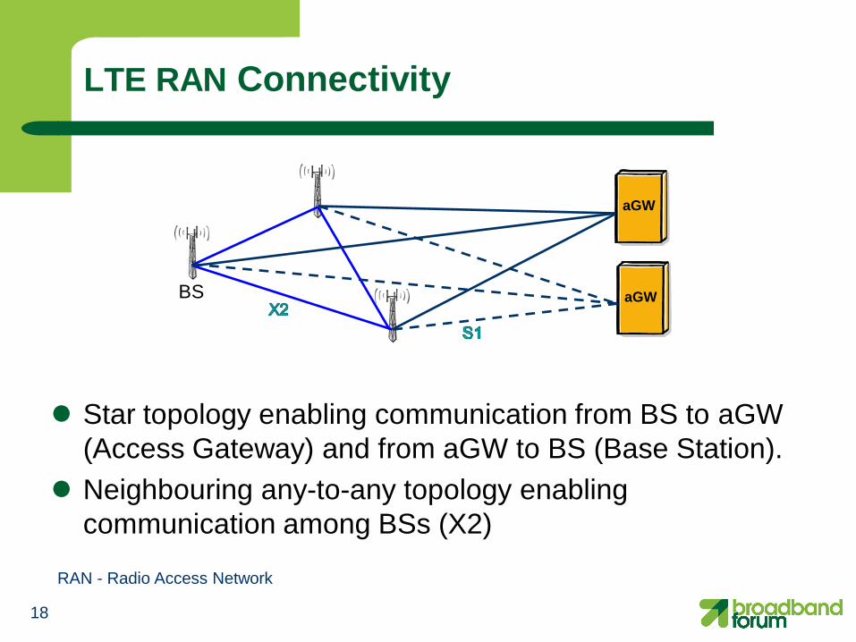
LTE RAN Connectivity
Star topology enabling communication from BS to aGW
(Access Gateway) and from aGW to BS (Base Station).
Neighbouring any-to-any topology enabling
communication among BSs (X2)
aGW
aGW
RAN - Radio Access Network
BS

19
MPLS is THE unifying technology for various backhaul
types
MPLS is proven in Service Provider deployments
globally – it delivers on its promises
MPLS adds carrier-grade capabilities – Scalability - millions of users/end points
– Resiliency - high availability including rapid restoration
– Manageability – ease of troubleshooting & provisioning
– Traffic Engineering plus QoS – predictable network behavior
– Multiservice – support for 2G (TDM), 3G (ATM, PPP/HDLC and IP),
and LTE (IP) and co-existence with other types of traffic e.g.
residential
– Virtualization – VPNs to ensure separation of OAM from
signaling / bearer planes, partitioning of multi-operator traffic
Why MPLS?

20
Backhaul requires co-existence of multiple transport options – MPLS is a proven mechanism to support ATM, TDM, Ethernet, Frame Relay
emulation (Pseudo-wires)
– Allows legacy RAN equipment to continue to be utilized (CAPEX protection) while leveraging the advantages of new packet transport networks
Packet Backhaul needs to support multi-media traffic – Voice/VoIP, Video/Multimedia, SMS, Data – MPLS –TE enables advanced QoS capability – Improved network utilization, Better ROI
Reliability is critical – MPLS offers faster convergence and interoperable mechanisms for failure
detection and recovery
Backhaul is increasingly becoming a strategic asset – MPLS at cell site enabled carriers to offer new revenue generating services
(i.e. L2/L3 VPNs)
Why IP/MPLS in Mobile Backhaul?
Scalability
IP/MPLS
Resiliency Multi-Service Manageability TE/QOS
21
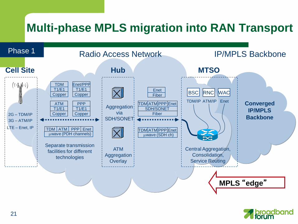
IP/MPLS Backbone Radio Access Network
Multi-phase MPLS migration into RAN Transport
Hub Cell Site
2G – TDM/IP
3G – ATM/IP
Phase 1
MPLS “edge”
MTSO
Converged
IP/MPLS
Backbone
TDM/IP ATM/IP Enet
BSC RNC WAC
TDM ATM PPP Enet wave (PDH channels)
Separate transmission
facilities for different
technologies
ATM
T1/E1
Copper
PPP
T1/E1
Copper
TDM
T1/E1
Copper
Enet/PPP
T1/E1
Copper
Central Aggregation,
Consolidation,
Service Routing
LTE – Enet, IP
Aggregation
via
SDH/SONET
ATM
Aggregation
Overlay
TDM PPP
SDH/SONET
Fiber
ATM Enet
TDM PPP ATM Enet wave (SDH ch)
Enet
Fiber

22
IP/MPLS Backbone Radio Access Network
Multi-phase MPLS migration into RAN Transport
Hub Cell Site
2G – TDM/IP
3G – ATM/IP
Phase 2
MPLS
Aggregation
for all
Technologies
MPLS
Ethernet ch
wave
MPLS
Ethernet
fiber
MPLS “edge”
MTSO
Converged
IP/MPLS
Backbone
TDM/IP ATM/IP Enet
BSC RNC WAC
MPLS
SDH/SONET
fiber
TDM ATM PPP Enet wave (PDH channels)
Separate transmission
facilities for different
technologies Common facility for
all traffic
TDM PPP ATM Enet
TDM PPP ATM Enet
TDM PPP ATM Enet
ATM
T1/E1
Copper
PPP
T1/E1
Copper
TDM
T1/E1
Copper
Enet/PPP
T1/E1
Copper
Central Aggregation,
Consolidation,
Service Routing
LTE – Enet, IP

23
IP/MPLS Backbone Radio Access Network
Multi-phase MPLS migration into RAN Transport
Hub Cell Site
2G – TDM/IP 3G – ATM/IP
Phase 3
MPLS “edge”
MTSO
Converged
IP/MPLS
Backbone
TDM/IP ATM/IP Enet
BSC RNC WAC
Router
TDM ATM
MPLS
Ethernet ch
wave
Enet
TDM ATM
MPLS
Ethernet
fiber
Enet
TDM ATM
MPLS
SDH/SONET
fiber
Enet
Common facility for
all traffic
TDM MPLS
Ethernet ch
wave
Enet
TDM
MPLS
Ethernet
fiber
Enet
TDM
MPLS
SDH/SONET
fiber
Enet
Common facility for
all traffic
IP
IP
ATM
ATM
IP ATM
MPLS
Aggregation
for all
Technologies
MPLS
Aggregation
for all
Technologies
MPLS is agnostic to transmission techniques in Access
LTE – Enet, IP

24 24
Mobile Backhaul Standards Landscape
3GPP
– RAN definition and specification – definition of the RAN and its interfaces
Broadband Forum
– TR-221 – architecture of mobile backhaul transport support with MPLS
– TR-221 Amd-1 (work in progress) – scaling and resiliency of the mobile backhaul network (for example small cell deployment)
– WT-145 – next generation broadband network architecture to support mobile backhaul
– Certification – certification of MPLS technologies to support mobile backhaul transport
– Tutorials – education on MPLS in mobile backhaul transport
MEF
– MEF-22.1 – Metro Ethernet services and interfaces required to support mobile backhaul
– Mobile Backhaul Whitepapers and Tutorial
ITU-T SG 15
– Specification for Clock Synchronization over packet network

What is MMBI? MPLS in Mobile Backhaul (MMBI)
MPLS in Mobile Backhaul (MMBI) is a technical initiative started in
2007 by the IP/MPLS Forum and adopted by the Broadband
Forum
The initiative currently consists of
– Architecture and nodal requirements specifications
– Test specifications
– Certification programs related to mobile backhaul (e.g., TDM
over MPLS)
– Whitepapers
– Tutorials (such as this one)
There are currently 7 specifications
More specifications are in progress to address mobile backhaul of
LTE and beyond.
25

26
What MMBI aims to address?
Faster mobile broadband deployment
– HSPA/HSPA+/LTE/LTE-A
Supporting 4G/LTE-Advanced features
Enhanced experience for mobile users with new data
services and application, along with voice
– Location based service, VoIP, gaming, etc
Future-proof investments
Improve mobile operator’s bottom line and simplify
operations
– Converging technology specific backhaul networks to single
multi-service packet infrastructure
– Based on proven benefits of IP/MPLS while leveraging cost-
benefits of Ethernet

27
MMBI Reference Architecture
Terminology WCDMA/
UMTS CDMA 2000/1x
LTE
Base Station Node-B BTS eNB
Base Station Controller RNC BSC -
Circuit Edge devices MSC MSC -
Packet Edge devices SGSN, GGSN PDSN S-GW / MME
HDLC TNL
HDLC TNL
Mobile Aggregation Site Gateway
IP TNL
ATM TNL
TDM TNL
IP TNL
ATM TNL
TDM TNL
Aggregation network
BS Access Aggregation
Access
network
xDSL,
microwave,
Leased
Line,
GPON,
Optical Eth
Access Node
Cell Site Gateway
Edge Node
IP/MPLS
Core
mobile network
Core
Iur
Abis A
Iub
Iub/S1
Iub
RC /
MME / S-GW
Iu-CS Iu-PS
MPLS transport network
Gb
Iu-PS
Iu-CS
A Gb Abis MSC 3G
SGSN 3G
SGSN 2G
MSC 2G
Abis Abis
Edge Node
Edge Node
Edge Node
Iub/S1
S5/S8A
MPLS PE function could be integrated into the BS (BTS/Node B/BS)/RC
PDN GW
S5/S8A
RAN

Ethernet and IP VPN Backhaul Architecture

IP TNL with L2VPN (Transport Network Layer)
VPLS - Virtual Private LAN Service
H-VPLS - Hierarchical Virtual Private LAN Service
VPWS - Virtual Private Wire Service 29

VPLS (Access & Aggregation)
Virtual Switching Instance (VSI) per Cell Site:
• Network is made up of many VPLS instances (3 nodes in each)
• LSP-based protection is mandatory (from all flavours of MPLS)
• Protection against a node failure at the switch site (PE or Router)
• VRRP runs between the switch site routers
PE
PE PE MPLS
(VPLS)
PE
Bidirectional PW
Ethernet link
VSI instance
Switch Site
S-GW
30

VPLS and Ethernet
PE
PE MPLS
(VPLS)
PE
Bidirectional PW
Ethernet link
VSI instance
Switch Site
C-VLAN S-VLAN PW LSP
C-VLAN from
cell sites
S+C VLAN in
PB domain
S-Tag is stripped at ingress
side of PE
S-Tag is put back egress
side of PE
IP S-VLAN
Ethernet
S-GW
RNC
BSC
31

VPWS (Access & Aggregation)
PW Redundancy group per Cell Site:
• Network is made up of many VPWS instances
• LSP-based protection is mandatory (from all flavours of MPLS)
• Protection against a node failure at the switch site (PE or Router)
• PW Redundancy runs in Independent mode from each Cell Site
PE
PE PE MPLS
(VPWS)
PE
Active PW
Ethernet link
Switch Site
Standby PW
S-GW
32

VPWS and Ethernet
PE
PE
MPLS
(VPWS)
PE Switch Site
C-VLAN S-VLAN PW LSP
C-VLAN from
cell sites
S+C VLAN in
PB domain
S-Tag is stripped at ingress
side of PE
S-Tag is put back egress
side of PE
IP S-VLAN
Active PW
Ethernet link
Standby PW
Ethernet
S-GW
33

IP TNL with L3VPN (Transport Network Layer)
34

L3VPN (Access & Aggregation)
Multiple VPN Routing and Forwarding (VRF) instances:
• One VRF for RAN management traffic (security)
• One VRF for all other RAN traffic (CDMA, 2G, 3G, LTE)
• Single IP address space for the RAN no further VRFs necessary
• Single or Multiple Autonomous System (AS) options for scalability
PE
PE PE MPLS
(L3VPN)
PE
VRF connectivity
Ethernet link
VRF instance
Switch Site
S-GW
35
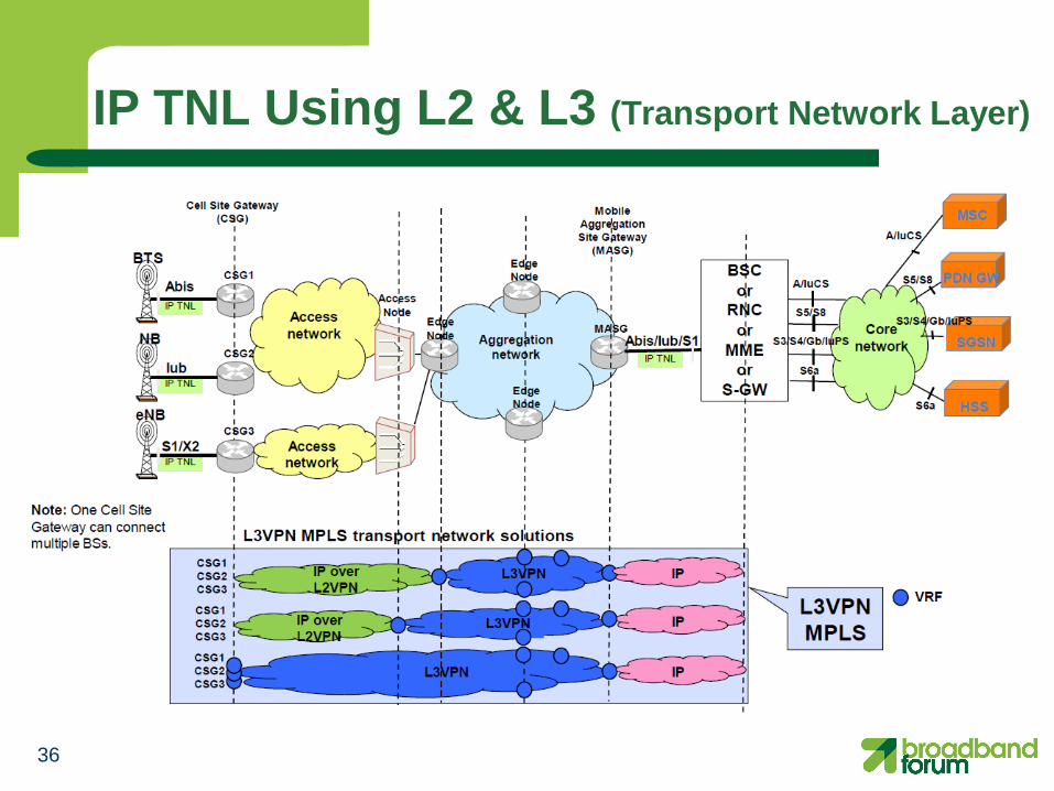
IP TNL Using L2 & L3 (Transport Network Layer)
36

L3VPN and Ethernet
PE
PE
MPLS
(L3VPN)
PE
VRF connectvity
Ethernet link
VRF instance
Switch Site
C-VLAN S-VLAN VRF LSP
C-VLAN from
cell sites
S+C VLAN in
PB domain
S-Tag is stripped at ingress
side of PE
VRF terminated in the
switch site router
IP
Ethernet
S-GW
37

Timing and Synchronization

39
The Need for Synchronization in Mobile Networks
Synchronization is vital across many elements in the mobile network
In the Radio Access Network (RAN), the need is focused in three principal areas
NodeB
NobeB
eNB or BS
eNB or BS
RNC
aGW
RNC
1: Radio Framing
Accuracy
2 : Handoff
Control 3 : Backhaul
Transport Reliability
Mobile Core
Network(s)

40
Radio Framing Accuracy
In Time Division Duplexing (TDD), the base station clocks must be
time synchronized to ensure no overlap of their transmissions within
the TDD frames
– Ensuring synchronization allows for tighter accuracies and reduced
guard-bands to ensure high bandwidth utilization
In Frequency Division Duplexing (FDD) the centre frequencies must
be accurate for receivers to lock

41
Radio Framing Accuracy
Radio Frequency Accuracy
LTE TDD/FDD: 50 ppb
LTE – A TDD/FDD: 50 ppb
Radio Phase/ToD Accuracy
LTE TDD: +/-1.5 μs
LTE-A with eICIC/CoMP: +/-1.5 - 5 μs
ToD – Time of Day
eICIC - Enhanced inter-cell interference coordination
CoMP - Coordinated multiple point
TA=1/fA
TB=1/fB
fA=fB
Frequency Synchronization
A
B t
t
TA=1/fA
TB=1/fB
fA=fB
Phase Synchronization
A
B

42
Handoff Control For Reliable Mobility Performance
Synchronization is vital to ensure service continuity
(i.e. successful handoff)
Studies have shown significant reduction in call drops when
good synchronization is in place; enhanced QoE

43
Backhaul Transport Reliability
Wander and Jitter in the Backhaul and Aggregation Network can
cause underflows and overflows
Slips in the PDH framing will cause bit errors leading to packet
rejections
Packet rejections lead to retransmissions and major perceptible
slow down in TCP windowed sessions
aGW/
RNC/
BSC
eNB/BS/
NodeB/BTS X
TCP end-to-end windowed transmission
Backhaul network

44
Timing Distribution Methods
External Timing Source – GPS
Physical layer clock – Using synchronous TDM interfaces, e.g. PDH/SDH
– Using synchronous Ethernet as per G.8261/G.8262, and G.8264 for ESMC/SSM
Physical Timing distribution over packet network – IEEE 1588-2008 / ITU G.8265
– NTP
– Adaptive Clock Recovery
– Differential Clock
Multiple methods might be deployed in a network Note: Both GPS and IEEE1588-2008 support frequency and phase, there is ITU-T work in progress on the telecom profiles for phase/Time of Day support

Quality of Service Requirements
Quality of Service (QoS) capabilities of MPLS mobile backhaul networks

Quality of Service Requirements
Supports QoS and service level agreements
Uses IETF DiffServ Architecture (RFC 2475)
Supports at least 4 CoS and associated service metrics (e.g., delay, delay variation, packet loss).
Supports Connection Admission Control to guarantee sufficient bandwidth is available to support new connections conforming to all SLAs.
SLAs are enforced using functions such as policing/shaping, marking and hierarchical scheduling.
Supports the pipe model of RFC 3270. Supports both E-LSPs and L-LSPs.
Supports mapping between the QoS of the TNL and TC bits of the LSP labels.
46

Resiliency, Protection and Performance
Operations, Administration and Management (OAM) and Resiliency

48
OAM Requirements
OAM needed for reactive & proactive network maintenance – Quick detection and localization of a defect
– Proactive connectivity verification and performance monitoring
OAM tools have a cost and revenue impact to carriers – Reduce troubleshooting time and therefore reduce
OPEX
– Enable delivery of high-margin premium services which require a short restoration time
Top level requirements – Provide/co-ordinate OAM at relevant levels in
IP/MPLS network
– Proactive and reactive mechanisms, independent at all levels
SOAM – Service OAN
VCCV - Virtual Circuit Connectivity Verification
Service Level e.g. Eth SOAM, L3 VPN
PW Level e.g. VCCV, PW status
Tunnel LSP Level e.g. LSP ping

49
Service and Transport OAM
Service and Transport OAM rely on the same set of protocols
Service OAM is a service-oriented mechanism that operate and manages end-to-end service – IP/MPLS VPN service OAM and PM
IP and VRF ping and trace route
BFD
PM based on RFC 6374
– Ethernet Service OAM and PM 802.1ag Connectivity Fault Management (CFM)
ITU-T Y.1731 PM for Ethernet services
Transport OAM is a network-oriented mechanism and manages the network infrastruture. – IP/MPLS VPN service OAM and PM (Performance
Monitoring) BFD (Bidirectional Forwarding Detection)
LSP ping and traceroute
PW – VCCV and Status

50
Service-Aware OAM Toolkit
Tool set for reactive & proactive network operation and maintenance Defect detection, proactive connectivity verification, and performance monitoring
Provide/co-ordinate OAM at relevant levels in IP/MPLS network
–Services Level: Eth SOAM, ATM OAM, IP/MPLS VPN Service OAM
–Tunnel LSP Level: LSP ping and LSP Traceroute
–Pseudowire Level: PW Status, VCCV-BFD, VCCV-Ping, mapping to Ethernet, TDM, ATM notifications
MPLS has been extended to provide additional capabilities for performance monitoring, path segment monitoring and alarm suppression
Quickly isolate and troubleshoot faults to reduce MTTR
BTS
2G
eNB, BS
4G
Node B
3G
Pseudowires
Tunnel LSP
MPLS Aggregation MPLS
Access
Hub
Cell Site
MTSO
PW Level e.g BFD, VCCV, PW status
Service Level e.g ATM OAM, SDP-Ping
Tunnel / LSP Level e.g LSP Ping & Traceroute

51
LSP Ping
LSP Ping is MPLS specific variation of traditional ICMP (Internet Control Message Protocol) ping/traceroute ad hoc tool – Ping is simple e2e loopback
– Traceroute uses TTL (Time to Live) to incrementally verify path
Ping paradigm useful for craftsperson initiated testing – TELNET/CLI
LSP Ping is augmented with a number of TLVs (Type Length Value)
processed by the receiver to extend functionality
As LSP is unidirectional, and Ping is bi-directional, LSP Ping is augmented with options for distinguishing real problems from return path problems

52
Bidirectional Forwarding Detection (BFD)
Simple, fixed-field, hello protocol – Easily implemented in hardware
– Very useful as a fault-detection mechanism
Nodes transmit BFD packets periodically over respective directions of a path
If a node stops receiving BFD packets some component of the bidirectional path is assumed to have failed
Applicable to tunnel end-points

53
Virtual Circuit Connection Verification (VCCV)
Mechanism for connectivity verification of PW
Multiple PSN tunnel types
– MPLS, GRE,…
Motivation
– One tunnel can serve many pseudo-wires
– MPLS LSP ping is sufficient to monitor the PSN tunnel (PE-PE connectivity), but not PWs inside of tunnel
Features
– Works over MPLS or IP networks
– In-band CV via control word flag or out-of-band option by inserting router alert label between tunnel and PW labels
– Works with BFD, and/or LSP ping
PE2 PE1
Attachment Circuit
Attachment Circuit
PSN
Pseudowire
4G-3G-2G
aGW/
HBSC/RNC Complex
BTS 2G
eNB, BS 4G
Node B 3G

54
PW Status Signaling
PWs have OAM capabilities to signal defect notifications:
Defect status mapped between AC and PW in the PE
PW status signaling propagates defect notifications along PW
- Extension to T-LDP signaling
PE2 PE1
Attachment Circuit
Attachment Circuit
PSN
Pseudowire
AC defect PW status: AC RX fault AC defect
4G-3G-2G
aGW/
HBSC/RNC Complex
BTS 2G
eNB, BS 4G
Node B 3G

55
PW Status Signaling: Multi-segment PWs
PW status signalling also works for MS-PWs
S-PEs:
– Transparently pass remote defect notifications
– Generate notifications of local defects
Pseudowires
S-PE T-PE Tunnel LSP
MPLS Aggregation MPLS
Access
Hub
Cell Site
MTSO
T-PE
PW Status BTS
2G
eNB, BS
4G
Node B
3G

56
Network Level Recovery
Dual-homing w/o RSTP
MPLS FRR (Fast Reroute)
MPLS Standby Secondary
Sub 50 ms restoration
End-to-end path protection
MPLS extensions to include
additional approaches
MPLS Network Reliability
Both node level and network level recovery are required
aGW/ RNC
MPLS Network
Ethernet
ATM (IMA)
active
standby
Node Level Recovery
Non-stop routing for ALL protocols (LDP,
OSPF, IS-IS, BGP, multicast, PIM-SM)
Non-Stop Service for ALL services (VPLS,
VLL, IP-VPN, IES (Internet-Enhanced
Service), multicast)
eNB, BS
4G
Node B
3G

57
Network Level Redundancy for PWs
Protects against PE and AC failures
PE configured with multiple pseudowires per service with multiple end-points
Local precedence indicates primary PW for forwarding if multiple PWs are operationally UP
PW status exchanged end-to-end to notify PEs of operational state of both PWs & ports / attachment circuits (PW Status Notification).
RFC-5718 PW Redundancy & draft-ietf-pwe3-redundancy-bit
aGW/ RNC
MPLS RAN
active
standby
AC redundancy protocol drives
forwarding state of PWs/PEs
Forwarding direction
determined by PW state
PW status
Active/standby state of
LAG sub-groups
reflected in PW status
Ethernet
ATM (IMA)
eNB, BS
4G
Node B
3G

58
MPLS Service Restoration Capabilities
Supports speedy detection and location of failure
LSP protection – End-to-end LSP protection and segment protection
– Link and Node protection with RSVP-TE FRR
– Loop-free alternate (LFA) adds fast reroute capability to IS-IS, OSPF and LDP. It is a local repair.
– Combining FRR and LFA provide deterministic service restoration
– Fast BFD
– Support graceful restart of protocols
PW protection – BFD-VCCV triggered restoration
– Redundant PW

IPv6 Considerations

IPv6 Considerations
Mobile backhaul network architectures use: – Layer 2 network (native, emulated or both)
– Layer 3 network (routed IP or IP VPN)
– Combination of both
Layer 2 – agnostic to IPv6 – IPv6 is carried transparently as payload to the mobile backhaul
network
– QoS from IPv6 should be mapped onto MPLS and layer 2 QoS
mechanisms
Layer 3 – must be v6 aware – IPVPN for v6 (“6VPE”) can be used to support a IPVPN that routes
IPv6 traffic. VPE is needed for VPN separation
– Not used today as most v6 is encapsulated in layers over IPv4 60

Energy Efficiency

Energy Efficiency
Motivation:
– Increasing energy cost and regulatory initiatives
– Increasing network infrastructure and data hungry applications
Energy Efficient Mobile Backhaul: A Holistic Approach
– Energy Efficient Network Planning (BBF Architecture)
Converged transport over MPLS architecture - Network Virtualization
– Introduce fewer “boxes”, unifies 2G/UMTS/HSDPA/LTE
– Encourages sharing
– Nodal Requirements
Energy Efficient Network Equipment
Network Based Energy Conservation
– Energy Saving Management
Main Contributions:
– RAN Technology Independent
– Align RAN and Core Network Energy
– Holistic Approach
62

Relationship to MEF 22.1 Mobile Backhaul IA

MPLS provides MEF service
64

MPLS uses MEF service
CSG - Cell Site Gateway
GIWF – Generic Interworking Function
TNL – Transport Network Layer 65
Notes:
• Ethernet CES GIWF (MEF 3, 8) not mentioned since transparent to MPLS
• The MEF cloud can be at the aggregation network, the access network, or both
Deployment Examples

67
Other Factors for Choice of Deployment
Network size (small and large)
Support legacy 2G/3G services and flexible any-to-any connectivity for LTE. The mobile network evolving to an all-IP network.
Scaling MPLS to support large number of Cell Site Gateways.
The architecture model can support large geographies and support hierarchical LSPs.
Optimized for advanced 4G requirements like IPSec and
authentication, eNodeB X2 interface communication
Operators may choice deployment scenario based on
organization, skill and service.

Security Considerations
IPsec not mandatory but likely to be used – IPsec tunnels between eNB and Security Gateway function
(control only or both)
– Some care needed to evaluate the architecture
– SeGW (Security Gateway) position and Distribution of credentials of Network Elements
Match the security architecture with the transport architecture
(logical connectivity, traffic steering)
Trade-off between performance and security
Security considerations depend on “trusted” analysis of Operator
See White Paper by the NGMN Alliance - Security in LTE backhauling http://www.ngmn.org/uploads/media/NGMN_Whitepaper_Backhaul_Security.pdf
68

69
Backhaul Deployment Scenarios
NGMN Alliance white paper on LTE backhaul provides: – Reference architecture and frame work
– LTE backhaul deployment scenarios and applicability
BBF TR-221 support all proposed NGMN deployment scenarios
Examples are based on the L2 and L3 protocols forecast – Supports both TDM and IP TNLs in the access.
– LTE is evolving to an all-IP network.
– Limited use of VPLS
Example of scenarios – Example 1: Access - PWs (Static or dynamic) + L3 VPN in
Aggregation Point-to-point MPLS Pseudowires in Access. Layer 3 VPNs in Aggregation
network.
– Example 2: MPLS PWs in both Access & Aggregation PWs (Static or dynamic) in Access network and PWs (dynamic) in
Aggregation network.
– Example 3: L3 VPNs in access and aggregation networks

LTE Deployment Example – VPWS in Access + L3 VPN in Aggregation
70
Note: One Cell Site Gateway
can connect multiple BSs.
Core
Network
(L3 VPN)
Access
Network
PWs
(Static or dynamic)
Aggregation network
(L3 VPN)
IP TNL
Mobile
Aggregation Site Gateway (MASG)
TDM TNL
BTS
Cell Site Gateway
(CSG)
Edge
Node
Edge
Node
A bis
IP TNL
CSG1
CSG2
CSG3
Access
network
NB
eNB
Edge
Node
Iub
S1/X2
MASG
Access
Node
X2
Ethernet
IP
L3 VPNMPLS PSN tunnel
Ethernet/DWDM
TDM
Controller
Ethernet
PWsStatic/Dynamic
S1

LTE Deployment Example – PW in both Access & Aggregation
71
Note: One Cell Site Gateway
can connect multiple BSs.
Core
Network
Access
Network
PWS(Static or Dynamic)
Aggregation network
PWS
(Dynamic)IP TNL
Mobile
Aggregation Site
Gateway (MASG)
TDM TNL
BTS
Cell Site Gateway
(CSG)
Edge
Node
Edge
Node
A bis
IP TNL
CSG1
CSG2
CSG3
Access
network
NB
eNB
Edge
Node
Iub
S1/X2
MASG
Access
Node
S1
Ethernet
IP
Ethernet/
DWDM
TDM
Controller
Ethernet
PW/MS-PW
Static or Dynamic
X2

LTE Deployment Example – L3 VPN in both Access & Aggregation
72
Note: One Cell Site Gateway
can connect multiple BSs.
Core
Network
(L3 VPN)
Access
Network
L3VPNAggregation network
(L3 VPN)
IP TNL
Mobile
Aggregation Site
Gateway (MASG)
IP TNL
eNB
Cell Site Gateway
(CSG)
Edge
Node
Edge
Node
S1/X2
IP TNL
CSG1
CSG2
CSG3
Access
network
NB
eNB
Edge
Node
Iub
S1/X2
MASG
Access
Node
S1
Ethernet
IP
LSP(VRF)
MPLS PSN tunnel
Ethernet/
DWDM
Ethernet
Controller
BBF Mobile Backhaul Work Plan – 2012

MMBI Work Plan - 2012
74
Update per latest
meeting

Summary
Summary of Success
Factors
76
LTE networks will co-exist with 2G/3G/4G networks
MPLS architecture is an efficient way to support IP centric LTE network traffic
MPLS backhaul delivers the performance LTE requires
(latency, synchronization, resiliency, etc) and scalability to
address traffic growth
TR-221 technical specifications provide the backhaul foundation for 2G/3G/4G and Beyond
- Simplifies operations and improves operators’ bottom line
- Flexibly supports all NGMN deployment scenarios
Summary

Thank you for attending the MPLS Mobile Backhaul Evolution – 4G LTE and
Beyond tutorial
The Broadband Forum is a non-profit
corporation organized to create guidelines for
broadband network system development and
deployment. This Broadband Forum educational
presentation has been approved by members of
the Forum. This Broadband Forum educational
presentation is not binding on the Broadband
Forum, any of its members, or any developer or
service provider. This Broadband Forum
educational presentation is subject to change,
but only with approval of members of the
Forum. This educational presentation is
copyrighted by the Broadband Forum, and all
rights are reserved. Portions of this educational
presentation may be copyrighted by Broadband
Forum members or external sources.

78
3GPP: http://www.3gpp.org
Broadband Forum: http://www.broadband-forum.org
IEEE: http://www.ieee.org
IETF: http://www.ietf.org
ITU-T SG 15: http://www.itu.int/ITU-T/studygroups/com15/index.asp
Metro Ethernet Forum (MEF): http://metroethernetforum.org
Next Generation Mobile Network Initiative (NGMN): http://www.ngmn.org
Related Standards Organizations & Consortiums

79
Abbreviations
MASG – Mobile aggregation site gateway
MGW – Message gateway
MMBI – MPLS in mobile backhaul initiative
MME – Mobility management entity
MPLS – Multiprotocol label switching
MPLS-TP – MPLS Transport Profile
MSC – Mobile switching center
MTSO – Mobile telephone switching office
Node B – Base station transceiver with UMTS/WCDMA
PCRF – Policy and charging function
PDN – Packet data network
PDSN – Packet data serving node
PM – Performance Monitoring
P-GW – PDN gateway
PS – Packet switched
PW – Pseudowire
RAN – Radio access network
RNC – Radio network controller
RSVP – Resource reservation protocol
SeGW - Security Gateway
SGSN – Serving GPRS support node
S-GW – Serving gateway
SOAM – Service OAM
TE – Traffic engineering
TNL – Transport network layer
ToD – Time of Day
TLV - Type Length Value
TNL – Transport Network Layer
TTL – Time to Live
UE – User equipment
UMB – Ultra mobile broadband
UMTS – Universal mobile telecommunications system
VCCV - Virtual Circuit Connectivity Verification
VLAN – Virtual local area network
VoLTE – Voice over LTE
VPLS - Virtual Private LAN Service
VPWS - Virtual Private Wire Service
VPN – Virtual private network
2G – Second generation mobile network
3G – Third generation mobile network
4G – Fourth generation mobile network
AC – Attachment Ciruit
AG – Access gateway
aGW– Access gateway
ASN – Access service node
BFD - Bidirectional Forwarding Detection
BS – Base station
BSC – Base station controller
BTS – Base transceiver station
CDMA – Code division multiple access
CoMP - Coordinated multiple point
CS – Circuit switched
CSG – Cell site gateway
EDGE – Enhance data rates for GSM evolution
eICIC: Enhanced inter-cell interference coordination
eMBMS - evolved Multimedia Broadcast Multicast Service
eNB - – 4G/LTE base station
eNode B – 4G/LTE base station
EPC – Evolved packet core
EUTRAN – Evolved UTRAN
EV-DO – Evolution data optimized
FEC – Forwarding equivalence class
FRR – Fast Re-route
GGSN – Gateway GPRS support node
CSG - Cell Site Gateway
GIWF – Generic Interworking Function
GPRS – General packet radio service
GSM – Global system for mobile communications
GW – Gateway
HSPA – High speed packet access
HSS – Home subscriber server
H-VPLS - Hierarchical Virtual Private LAN Service
IES - Internet-Enhanced Service
ICMP - Internet Control Message Protocol
LSP – Label switched path
LTE – Long term evolution