Embed Size (px)
Citation preview
MPD 600
High-End Measurement and Analysis System for Partial Discharges
2
Partial Discharge Analysis
Partial Discharges: Weak Points in Insulation Systems
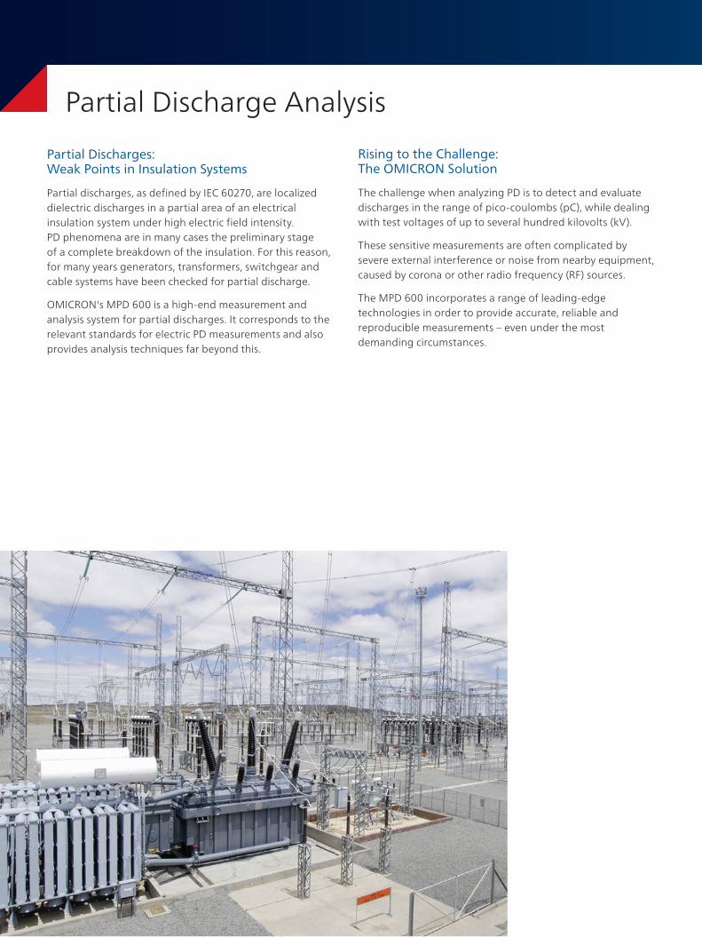
Partial discharges, as defined by IEC 60270, are localized dielectric discharges in a partial area of an electrical insulation system under high electric field intensity. PD phenomena are in many cases the preliminary stage of a complete breakdown of the insulation. For this reason, for many years generators, transformers, switchgear and cable systems have been checked for partial discharge.
OMICRON's MPD 600 is a high-end measurement and analysis system for partial discharges. It corresponds to the relevant standards for electric PD measurements and also provides analysis techniques far beyond this.
Rising to the Challenge: The OMICRON Solution
The challenge when analyzing PD is to detect and evaluate discharges in the range of pico-coulombs (pC), while dealing with test voltages of up to several hundred kilovolts (kV).
These sensitive measurements are often complicated by severe external interference or noise from nearby equipment, caused by corona or other radio frequency (RF) sources.
The MPD 600 incorporates a range of leading-edge technologies in order to provide accurate, reliable and reproducible measurements – even under the most demanding circumstances.
3
Partial Discharge Analysis
The System
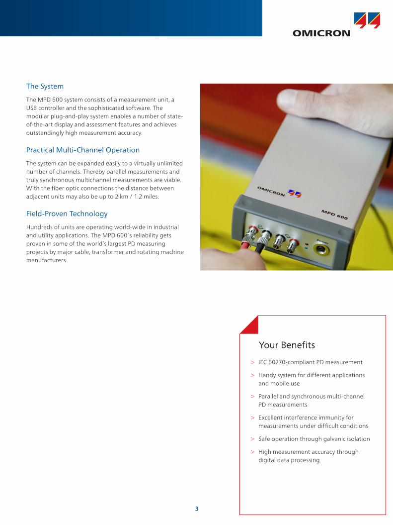
The MPD 600 system consists of a measurement unit, a USB controller and the sophisticated software. The modular plug-and-play system enables a number of state-of-the-art display and assessment features and achieves outstandingly high measurement accuracy.
Practical Multi-Channel Operation
The system can be expanded easily to a virtually unlimited number of channels. Thereby parallel measurements and truly synchronous multichannel measurements are viable. With the fiber optic connections the distance between adjacent units may also be up to 2 km / 1.2 miles.
Field-Proven Technology
Hundreds of units are operating world-wide in industrial and utility applications. The MPD 600 s reliability gets proven in some of the world’s largest PD measuring projects by major cable, transformer and rotating machine manufacturers.
Your Benefits
> IEC 60270-compliant PD measurement
> Handy system for different applications and mobile use
> Parallel and synchronous multi-channel PD measurements
> Excellent interference immunity for measurements under difficult conditions
> Safe operation through galvanic isolation
> High measurement accuracy through digital data processing
Effective Prevention of Interferences
A main problem during PD measurements is interferences caused by adjacent electrical equipment. These can make measurement, analysis and localization of PD signals very difficult or even impossible. The elimination or at least reduction of such interferences is critical for successful PD analysis.
Galvanic Isolation Through Fiber Optic Cable
The fiber optic transmission impresses with a complete galvanic isolation between the individual measuring devices and the PC controller. This minimizes ground loops, reduces interference coupling and achieves significantly higher system sensitivity through the improved signal-to-noise ratio.
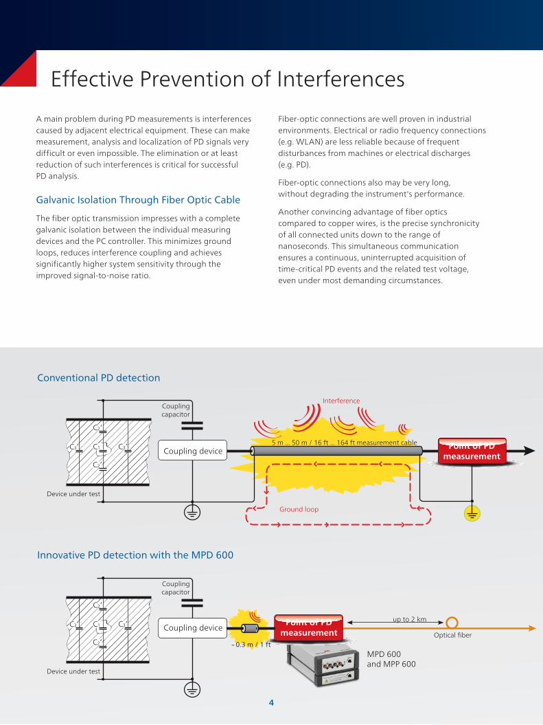
Conventional PD detection
Innovative PD detection with the MPD 600
Device under test
Coupling capacitor
Device under test
Coupling capacitor
C3’ C1
C2’
C2’
C3’
C3’ C1
C2’
C2’
C3’
Ground loop
C3’ C1
C2’
C2’
C3’
C3’ C1
C2’
C2’
C3’
Interference
Point of PD measurement
5 m ... 50 m / 16 ft ... 164 ft measurement cable
MPD 600 and MPP 600
Optical fiber
up to 2 kmPoint of PD measurement
~ 0.3 m / 1 ft
Fiber-optic connections are well proven in industrial environments. Electrical or radio frequency connections (e.g. WLAN) are less reliable because of frequent disturbances from machines or electrical discharges (e.g. PD).
Fiber-optic connections also may be very long, without degrading the instrument's performance.
Another convincing advantage of fiber optics compared to copper wires, is the precise synchronicity of all connected units down to the range of nanoseconds. This simultaneous communication ensures a continuous, uninterrupted acquisition of time-critical PD events and the related test voltage, even under most demanding circumstances.
Coupling device
Coupling device
4
Effective Prevention of Interferences
Advanced Fully Digital Filtering
From the first measuring point, MPD 600 uses a digital filter. Therefore, no aging effects or drift over time and temperature occurs, resulting in an exceptionally high degree of reproducibility to perform reliable, calibrated and traceable PD quality control.
Battery Powered Acquisition Units
During battery operation no noise from mains power supply enters the measuring circuit. This way the measurement unit can also be operated at high-voltage potential. Due to the very low power consumption, an uninterrupted battery operation of more than 20 hours is ensured.
C3’ C1
C2’
C2’
C3’
C3’ C1
C2’
C2’
C3’
C3’ C1
C2’
C2’
C3’
C3’ C1
C2’
C2’
C3’
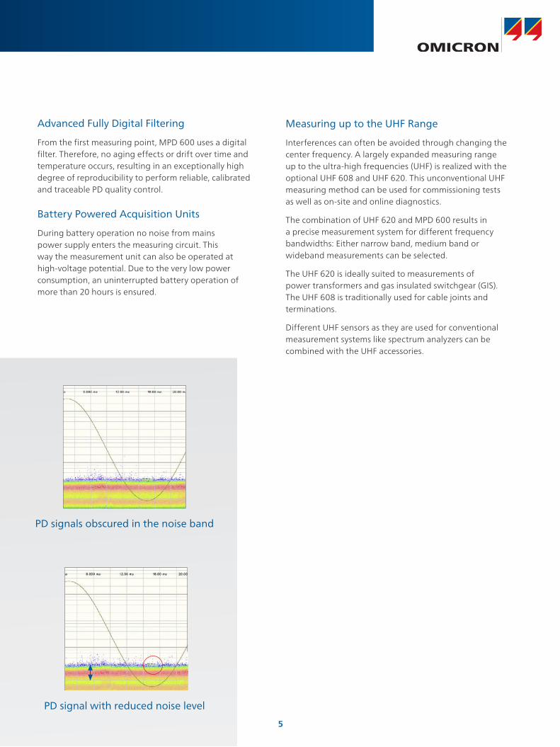
PD signals obscured in the noise band
Measuring up to the UHF Range
Interferences can often be avoided through changing the center frequency. A largely expanded measuring range up to the ultra-high frequencies (UHF) is realized with the optional UHF 608 and UHF 620. This unconventional UHF measuring method can be used for commissioning tests as well as on-site and online diagnostics.
The combination of UHF 620 and MPD 600 results in a precise measurement system for different frequency bandwidths: Either narrow band, medium band or wideband measurements can be selected.
The UHF 620 is ideally suited to measurements of power transformers and gas insulated switchgear (GIS). The UHF 608 is traditionally used for cable joints and terminations.
Different UHF sensors as they are used for conventional measurement systems like spectrum analyzers can be combined with the UHF accessories.
PD signal with reduced noise level
5
6
Basic Mode – Results by Mouse Click
In Basic Mode, most parameters and settings are automatically determined by the software, so the user can focus on performing the PD measurement.
> Highly responsive real-time display (> 20 frames /sec)
> Configurable real-time oscilloscope view for PD and V input
> Flexible PD event visualization, including the phase resolved histogram view, ellipse and real-time view
> Ellipse view for reproduction of a classical analog feel
Tailored MPD Software
Cable Mode – Guided Measurement
The Cable mode is an intuitive three-step interface for testing high-voltage cables. This module is used for quality assurance in the factory as well as fault localization on site.
The user is guided through the entire measurement. The detection of partial discharge faults in high-voltage cables, which is accurate to the meter, is thus particularly effective and precise.
2
6
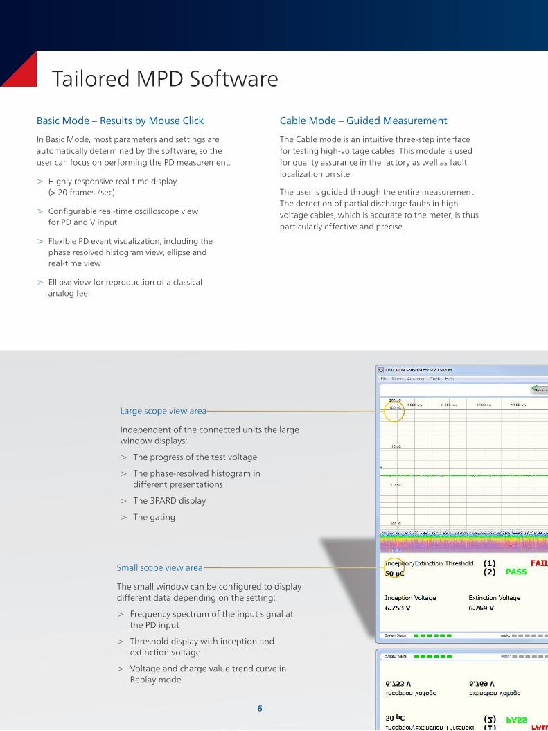
Small scope view area
The small window can be configured to display different data depending on the setting:
> Frequency spectrum of the input signal at the PD input
> Threshold display with inception and extinction voltage
> Voltage and charge value trend curve in Replay mode
Large scope view area
Independent of the connected units the large window displays:
> The progress of the test voltage
> The phase-resolved histogram in different presentations
> The 3PARD display
> The gating
Tailored MPD Software
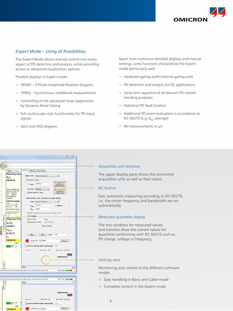
Measured quantities display
The two windows for measured values and statistics show the current values for quantities conforming with IEC 60270 such as: PD charge, voltage or frequency
Apart from numerous detailed displays and manual settings, some functions characterize the Expert mode particularly well:
> Hardware gating (with external gating unit)
> PD detection and analysis for DC applications
> Long-term aquistion of all relevant PD related trending purposes
> Statistical PD fault location
> Additional PD event evaluation in accordance to IEC 60270 (e.g. QIEC average)
> RIV measurements in μV
Expert Mode – Using all Possibilities
The Expert Mode allows manual control over every aspect of PD detection and analysis, while providing access to advanced visualization options.
Possible displays in Expert mode:
> 3PARD – 3-Phase Amplitude Relation Diagram
> 3FREQ – Synchronous multiband measurements
> Controlling of the advanced noise suppression by Dynamic Noise Gating
> Full oscilloscope style functionality for PD input signals
> Q(U) and H(Q) diagram
Acquisition unit selection
The upper display pane shows the connected acquisition units as well as their status
IEC button
Fast, automatic measuring according to IEC 60270, i.e., the center frequency and bandwidth are set automatically
7
Settings area
Monitoring and control of the different software modes:
> Easy handling in Basic and Cable mode
> Complete control in the Expert mode
8
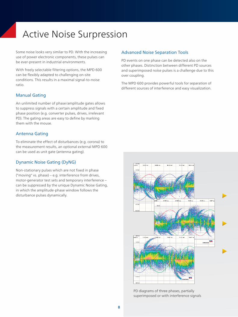
PD diagrams of three phases, partially superimposed or with interference signals
Active Noise Surpression
Some noise looks very similar to PD. With the increasing use of power electronic components, these pulses can be ever-present in industrial environments.
With freely selectable filtering options, the MPD 600 can be flexibly adapted to challenging on-site conditions. This results in a maximal signal-to-noise ratio.
Manual Gating
An unlimited number of phase/amplitude gates allows to suppress signals with a certain amplitude and fixed phase position (e.g. converter pulses, drives, irrelevant PD). The gating areas are easy to define by marking them with the mouse.
Antenna Gating
To eliminate the effect of disturbances (e.g. corona) to the measurement results, an optional external MPD 600 can be used as unit gate (antenna gating).
Dynamic Noise Gating (DyNG)
Non-stationary pulses which are not fixed in phase ("moving" vs. phase) – e.g. interference from drives, motor-generator test sets and temporary interference – can be suppressed by the unique Dynamic Noise Gating, in which the amplitude-phase window follows the disturbance pulses dynamically.
Advanced Noise Separation Tools
PD events on one phase can be detected also on the other phases. Distinction between different PD sources and superimposed noise pulses is a challenge due to this over coupling.
The MPD 600 provides powerful tools for separation of different sources of interference and easy visualization.
8
9
Active Noise Surpression
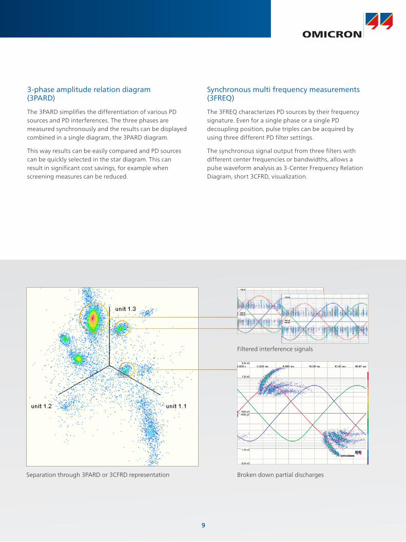
Synchronous multi frequency measurements (3FREQ)
The 3FREQ characterizes PD sources by their frequency signature. Even for a single phase or a single PD decoupling position, pulse triples can be acquired by using three different PD filter settings.
The synchronous signal output from three filters with different center frequencies or bandwidths, allows a pulse waveform analysis as 3-Center Frequency Relation Diagram, short 3CFRD, visualization.
Separation through 3PARD or 3CFRD representation Broken down partial discharges
Filtered interference signals
3-phase amplitude relation diagram (3PARD)
The 3PARD simplifies the differentiation of various PD sources and PD interferences. The three phases are measured synchronously and the results can be displayed combined in a single diagram, the 3PARD diagram.
This way results can be easily compared and PD sources can be quickly selected in the star diagram. This can result in significant cost savings, for example when screening measures can be reduced.
9

10
Post Processing of Realtime Data
In many cases there is insufficient time for further detailed analysis of the PD patterns or the changes which occurred during testing.
The MPD 600 can store PD events with very high sampling rate during testing. In addition, the test voltages and all other relevant system settings are also stored.
This creates a growing database, which can be used as reference for the interpretation of future measurement results.
Numerous functions are integrated into the MPD 600 system for safe and easy handling of the measured data.
Replay Function
By storing the measured data as unprocessed raw data, these can still be analyzed subsequently. The full set of analysis functions and the different tools like 3PARD or gating can be used for this - just as if the measurement was performed once again.
Streaming Function
The recorded measured data, so-called streams, can be cut individually, i.e. to focus on relevant PD events. As the playback speed can also be freely selected, some sections can be played back more slowly and thus be analyzed in greater detail.
Export Function
Recordings can also be stored as video in .avi format. With the compressed file size the videos are easier to handle, need less storage space and can be sent to experts as email attachment. In addition, the videos can also be played back without installed MPD software.
11
Post Processing of Realtime Data
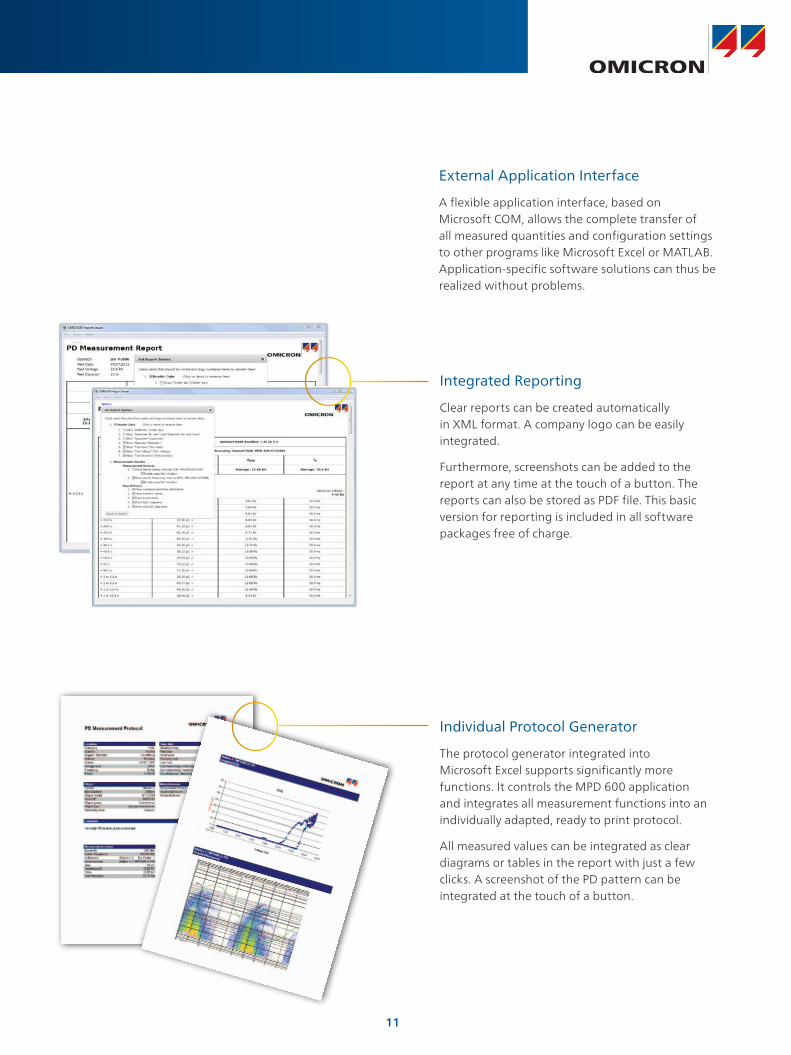
External Application Interface
A flexible application interface, based on Microsoft COM, allows the complete transfer of all measured quantities and configuration settings to other programs like Microsoft Excel or MATLAB. Application-specific software solutions can thus be realized without problems.
Integrated Reporting
Clear reports can be created automatically in XML format. A company logo can be easily integrated.
Furthermore, screenshots can be added to the report at any time at the touch of a button. The reports can also be stored as PDF file. This basic version for reporting is included in all software packages free of charge.
Individual Protocol Generator
The protocol generator integrated into Microsoft Excel supports significantly more functions. It controls the MPD 600 application and integrates all measurement functions into an individually adapted, ready to print protocol.
All measured values can be integrated as clear diagrams or tables in the report with just a few clicks. A screenshot of the PD pattern can be integrated at the touch of a button.

12
Applications and Software Packages
Multi-channel Measurements of Power Transformers
The MPD 600 enables the user to quickly measure all of the relevant quantities for a reliable PD measurement of power transformers. No matter whether the transformer is single or three-phase.
Localizing PD Failures Accurate to a Meter
Fault-finding in cables with the MPD 600 provides accuracy better than 0.2 % of the total cable length. PD faults can thus be localized with meter to centimeter precision. Therefore, during commissioning the focus is on quality control of cable accessories, such as joints and terminations.
Reliable Assessment of Rotating Machines
Rotating machines, industrial drives and railway transportation must be assessed offline or in operation. With the help of the MPD 600 and its unique functions, the difficulties of nearby interfering fields can be overcome much easier than other systems.
M/G
Precise Assessment in Factories and Laboratories
In shielded laboratories, PD measurements on high-voltage components are carried out using coupling capacitors and measuring impedances. After calibration, the MPD shows the apparent charge according to IEC 60270. PD analysis is supported by graphical tools such as the PRPD pattern.
PD Measurements on Gas-insulated Switchgear (GIS)
PD measurements within the ultra-high frequency range are very sensitive and therefore are used for PD detection in a long while. In new plants, UHF sensors are more and more integrated – alternatively, mobile and external sensors can be used. The combination of MPD 600 and OMICRON’s UHF 620 allows fast and easy PD measuring up to the UHF range and provides therefore different frequency bandwidths.
13
Applications and Software Packages
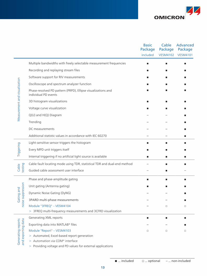
Basic Package
Cable Package
Advanced Package
included VESM4102 VESM4101
Mea
sure
men
t an
d v
isua
lizat
ion
Multiple bandwidths with freely selectable measurement frequencies
Recording and replaying stream files
Software support for RIV measurements
Oscilloscope and spectrum analyzer function
Phase-resolved PD pattern (PRPD), Ellipse visualizations and individual PD events
3D histogram visualizations
Voltage curve visualization
Q(U) and H(Q) Diagram – –
Trending – –
DC measurements – –
Additional statistic values in accordance with IEC 60270 – –
Trig
geri
ng Light-sensitive sensor triggers the histogram
Every MPD unit triggers itself
Internal triggering if no artificial light source is available
Cab
le
test
ing Cable fault locating mode using TDR, statistical TDR and dual-end method –
Guided cable assessment user interface – –
Gat
ing
and
no
ise
sup
pre
ssio
n
Phase and phase-amplitude gating
Unit gating (Antenna gating)
Dynamic Noise Gating (DyNG) – –
3PARD multi-phase measurements – –
Module "3FREQ" – VESM4104
> 3FREQ multi-frequency measurements and 3CFRD visualization
–
Gen
erat
ing
rep
orts
an
d e
xpor
ting
dat
a Generating XML reports
Exporting data into MATLAB® files – –
Module "Report" – VESM4103
> Automated, Excel-based report generation
> Automation via COM® interface
> Providing voltage and PD values for external applications
... included ... optional – ... non-included
14
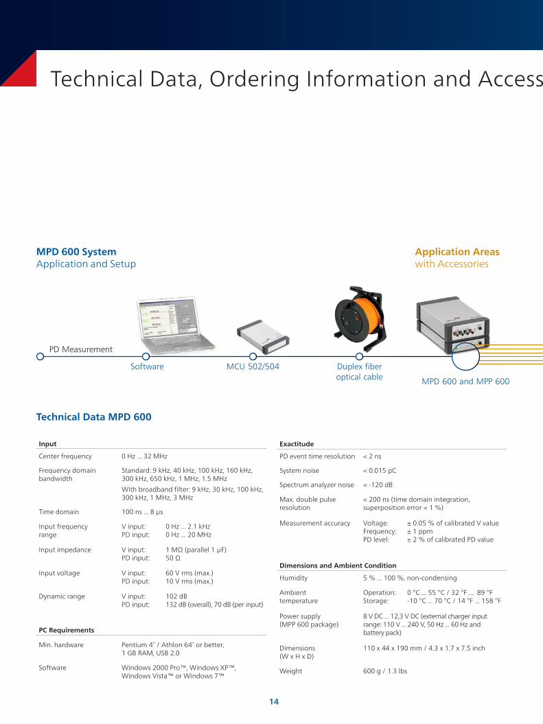
Technical Data, Ordering Information and Accessories
Input
Center frequency 0 Hz ... 32 MHz
Frequency domain bandwidth
Standard: 9 kHz, 40 kHz, 100 kHz, 160 kHz, 300 kHz, 650 kHz, 1 MHz, 1.5 MHz
With broadband filter: 9 kHz, 30 kHz, 100 kHz, 300 kHz, 1 MHz, 3 MHz
Time domain 100 ns ... 8 μs
Input frequency range
V input: 0 Hz ... 2.1 kHz PD input: 0 Hz ... 20 MHz
Input impedance V input: 1 MΩ (parallel 1 µF) PD input: 50 Ω
Input voltage V input: 60 V rms (max.) PD input: 10 V rms (max.)
Dynamic range V input: 102 dB PD input: 132 dB (overall), 70 dB (per input)
PC Requirements
Min. hardware Pentium 4® / Athlon 64® or better, 1 GB RAM, USB 2.0
Software Windows 2000 Pro™, Windows XP™, Windows Vista™ or Windows 7™
Exactitude
PD event time resolution < 2 ns
System noise < 0.015 pC
Spectrum analyzer noise < -120 dB
Max. double pulse resolution
< 200 ns (time domain integration, superposition error < 1 %)
Measurement accuracy
Voltage: ± 0.05 % of calibrated V value Frequency: ± 1 ppm PD level: ± 2 % of calibrated PD value
Dimensions and Ambient Condition
Humidity 5 % ... 100 %, non-condensing
Ambient temperature
Operation: 0 °C ... 55 °C / 32 °F ... 89 °F Storage: -10 °C ... 70 °C / 14 °F ... 158 °F
Power supply (MPP 600 package)
8 V DC ... 12,3 V DC (external charger input range: 110 V ... 240 V, 50 Hz ... 60 Hz and battery pack)
Dimensions (W x H x D)
110 x 44 x 190 mm / 4.3 x 1.7 x 7.5 inch
Weight 600 g / 1.3 lbs
Technical Data MPD 600
MPD 600 and MPP 600
Duplex fiber optical cable
MCU 502/504Software
PD Measurement
MPD 600 SystemApplication and Setup
Application Areaswith Accessories
15
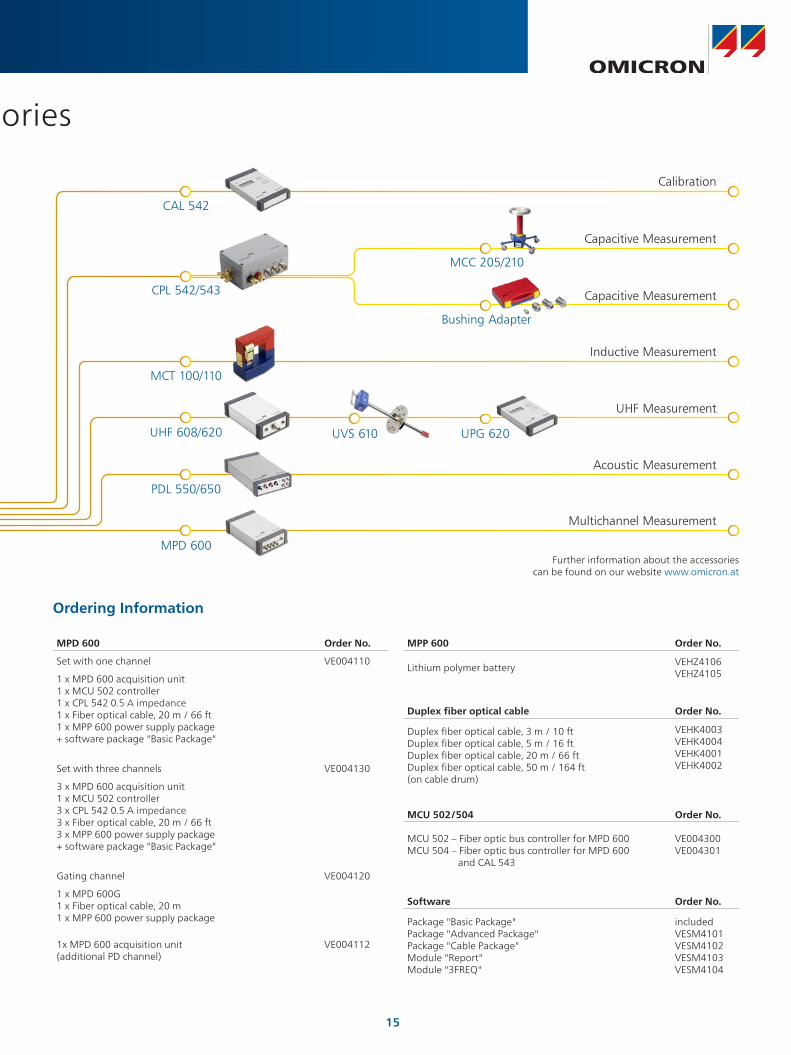
Technical Data, Ordering Information and Accessories
Capacitive Measurement
Capacitive Measurement
UHF Measurement
Inductive Measurement
Acoustic Measurement
Multichannel Measurement
CAL 542
MCT 100/110
UHF 608/620
PDL 550/650
MPD 600
Application Areaswith Accessories
UVS 610 UPG 620
MPD 600 Order No.
Set with one channel VE004110
1 x MPD 600 acquisition unit 1 x MCU 502 controller 1 x CPL 542 0.5 A impedance 1 x Fiber optical cable, 20 m / 66 ft 1 x MPP 600 power supply package + software package "Basic Package"
Set with three channels VE004130
3 x MPD 600 acquisition unit 1 x MCU 502 controller 3 x CPL 542 0.5 A impedance 3 x Fiber optical cable, 20 m / 66 ft 3 x MPP 600 power supply package + software package "Basic Package"
Gating channel VE004120
1 x MPD 600G 1 x Fiber optical cable, 20 m 1 x MPP 600 power supply package
1x MPD 600 acquisition unit (additional PD channel)
VE004112
MPP 600 Order No.
Lithium polymer batteryVEHZ4106 VEHZ4105
Duplex fiber optical cable Order No.
Duplex fiber optical cable, 3 m / 10 ft Duplex fiber optical cable, 5 m / 16 ft Duplex fiber optical cable, 20 m / 66 ft Duplex fiber optical cable, 50 m / 164 ft (on cable drum)
VEHK4003 VEHK4004 VEHK4001 VEHK4002
MCU 502/504 Order No.
MCU 502 – Fiber optic bus controller for MPD 600 MCU 504 – Fiber optic bus controller for MPD 600 and CAL 543
VE004300 VE004301
Software Order No.
Package "Basic Package" Package "Advanced Package" Package "Cable Package" Module "Report" Module "3FREQ"
included VESM4101 VESM4102 VESM4103 VESM4104
Ordering Information
Further information about the accessories can be found on our website www.omicron.at
Calibration
Bushing Adapter
MCC 205/210
CPL 542/543

AmericasOMICRON electronics Corp. USA3550 Willowbend BlvdHouston, TX 77054, USAPhone: +1 713 830-4660 +1 800-OMICRONFax: +1 713 [email protected]
© OMICRON L2069, November 2012Subject to change without notice
Asia-PacificOMICRON electronics Asia LimitedSuite 2006, 20/F, Tower 2The Gateway, Harbour CityKowloon, Hong Kong S.A.R.Phone: +852 3767 5500Fax: +852 3767 [email protected]
Europe, Middle East, AfricaOMICRON electronics GmbHOberes Ried 16833 Klaus, AustriaPhone: +43 5523 507-0Fax: +43 5523 [email protected]
www.omicron.at • www.omicronusa.com
MPD 500 Brochure
PDL 650 Brochure
MI 600 Brochure
The following publications provide further information on the solutions described in this brochure:
For a complete list of available literature please visit our website.
OMICRON is an international company serving the electrical power industry with innovative testing and diagnostic solutions. The application of OMICRON products allows users to assess the condition of the primary and secondary equipment on their systems with complete confidence. Services offered in the area of consulting, commissioning, testing, diagnosis and training make the product range complete.
Customers in more than 140 countries rely on the company’s ability to supply leading edge technology of excellent quality. Service centers on all continents provide a broad base of knowledge and extraordinary customer support. All of this together with our strong network of sales partners is what has made our company a market leader in the electrical power industry.