Embed Size (px)
Citation preview
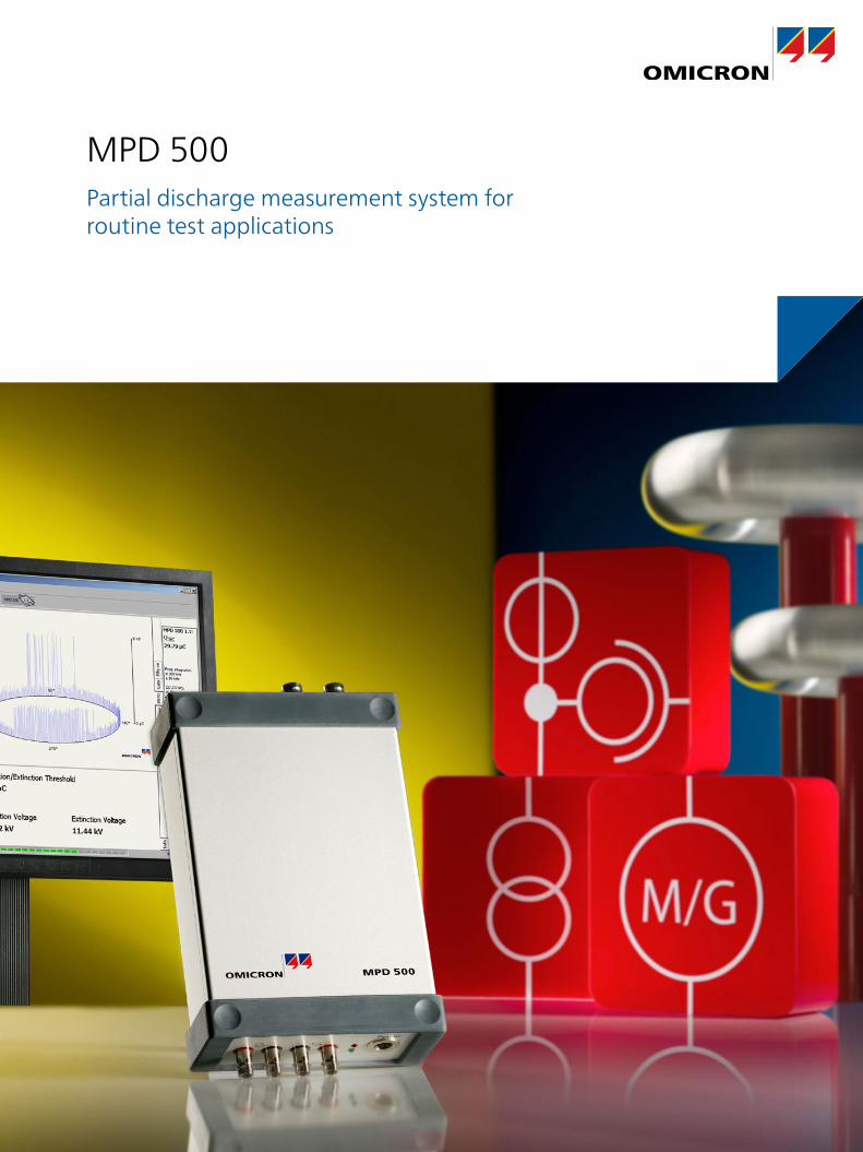
MPD 500Partial discharge measurement system for routine test applications
2
Reliable evaluation of insulating systems
Partial discharges (PD) are defined as localized electrical discharge that only partially bridge the insulation between conductors, often preceding an insulation breakdown. Therefore, PD measurements are well established and widely accepted for quality assurance and factory testing of medium- and high-voltage assets in a variety of power and industrial segments.
Modern PD measurement systems based on apparent charge [pC], in accordance with IEC 60270, reveals faulty spots in electrical insulations with a high degree of sensitivity.
Radio Influence Voltage (RIV) measurements express partial discharge activities as a voltage that appears on conductors of electric equipment. The RIV value is displayed in µV according to CISPR 16-1-1 and the still referenced NEMA 107-1987.
The most convenient way to measure PD
The MPD 500 benefits from the experience of hundreds of MPD 600 units in daily use by major cable-, transformer-, and rotating machine manufacturers worldwide.
By incorporating a wide range of leading-edge technologies, highly sensitive and accurate results can be obtained by the MPD 500 as easily as operating a voltmeter. The user-friendly software provides full remote control of the measurement devices and delivers very easy automated reporting of PD / RIV measurements. The MPD 500 also holds simultaneous multi-channel abilities, without the need for a multiplexer.
Partial discharge testing
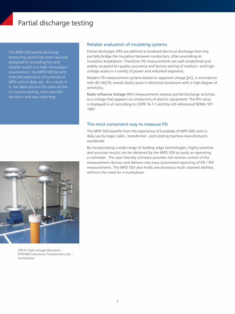
300 kV high-voltage laboratory PFIFFNER Instrument Transformers Ltd. / Switzerland
The MPD 500 partial discharge measuring system has been specially designed for providing fast and reliable results in a high-throughput environment. The MPD 500 benefits from the experience of hundreds of MPD units in daily use. As a result, it is the ideal solution for state-of-the-art routine testing, clear pass/fail decisions and easy reporting.
3
Results at one glance
Advantages of the intuitive MPD 500 software:
> Concise visualization of single as well as multi-channel measurements
> User-friendly “pass / fail” functionality
> Detailed diagrams for in-depth analysis
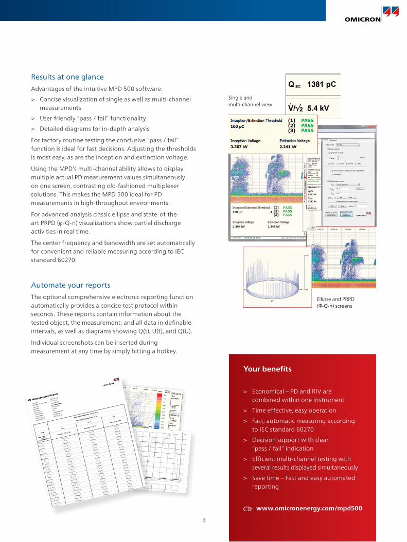
For factory routine testing the conclusive “pass / fail” function is ideal for fast decisions. Adjusting the thresholds is most easy, as are the inception and extinction voltage.
Using the MPD’s multi-channel ability allows to display multiple actual PD measurement values simultaneously on one screen, contrasting old-fashioned multiplexer solutions. This makes the MPD 500 ideal for PD measurements in high-throughput environments.
For advanced analysis classic ellipse and state-of-the-art PRPD (ϕ-Q-n) visualizations show partial discharge activities in real time.
The center frequency and bandwidth are set automatically for convenient and reliable measuring according to IEC standard 60270.
Partial discharge testing
Automate your reports
The optional comprehensive electronic reporting function automatically provides a concise test protocol within seconds. These reports contain information about the tested object, the measurement, and all data in definable intervals, as well as diagrams showing Q(t), U(t), and Q(U).
Individual screenshots can be inserted during measurement at any time by simply hitting a hotkey.
Ellipse and PRPD (Φ-Q-n) screens
Single and multi-channel view
Your benefits
> Economical – PD and RIV are combined within one instrument
> Time effective, easy operation
> Fast, automatic measuring according to IEC standard 60270
> Decision support with clear “pass / fail” indication
> Efficient multi-channel testing with several results displayed simultaneously
> Save time – Fast and easy automated reporting
www.omicronenergy.com/mpd500
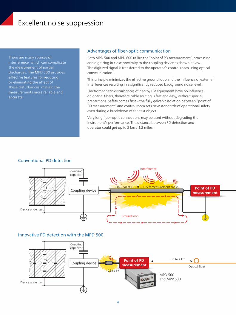
Excellent noise suppression
Advantages of fiber-optic communication
Both MPD 500 and MPD 600 utilize the “point of PD measurement”, processing and digitizing in close proximity to the coupling device as shown below. The digitized signal is transferred to the operator’s control room using optical communication.
This principle minimizes the effective ground loop and the influence of external interferences resulting in a significantly reduced background noise level.
Electromagnetic disturbances of nearby HV equipment have no influence on optical fibers, therefore cable routing is fast and easy, without special precautions. Safety comes first – the fully galvanic isolation between “point of PD measurement” and control room sets new standards of operational safety even during a breakdown of the test object.
Very long fiber-optic connections may be used without degrading the instrument’s performance. The distance between PD detection and operator could get up to 2 km / 1.2 miles.
There are many sources of interference, which can complicate the measurement of partial discharges. The MPD 500 provides effective features for reducing or eliminating the effect of these disturbances, making the measurements more reliable and accurate.
4
C3’ C1
C2’
C2’
C3’
C3’ C1
C2’
C2’
C3’
C3’ C1
C2’
C2’
C3’
C3’ C1
C2’
C2’
C3’
Conventional PD detection
Innovative PD detection with the MPD 500
Device under test
Coupling capacitor
Device under test
Coupling capacitor
Ground loop
Interference
Point of PD measurement
5 m ... 50 m / 16 ft ... 165 ft measurement cable
MPD 500 and MPP 600
Optical fiber
up to 2 kmPoint of PD measurement
~ 0.3 m / 1 ft
Coupling device
Coupling device
Routine factory testing
Routine PD measurements become easy with the integrated “pass / fail” functionality. Set the MPD 500 to the desired PD threshold level for the device under test. When this level is exceeded, it is clearly displayed in the main window.
For further investigations the MPD 500 provides advanced visualization and diagnosis tools such as ellipse and PRPD (ϕ-Q-n), typically only found in high-end PD measurement systems.
Wide range of applications
Upgrade your testing facility to the latest technical bench-mark in partial discharge measurements. The MPD 500 is ideal for examining PD faults in electrical insulations of transformers, bushings, generators, motors, and other types of electrical equipment in screened factory routine-testing environments, testing laboratories and industrial areas.
Adaptable to 19” format, the MPD 500 fills in for outdated built-in instruments. This drop-in boosts control rooms to state-of-the-art PD measuring abilities, with all benefits of a contemporary PD system. Each replacement gets optimized to the individual demands. Contact your OMICRON sales representative for further details.
Let the equipment grow with your needs
If necessary the MPD 500 can be upgraded to OMICRON’s well-established high-end MPD 600 PD measurement and analysis system at any time, even after several years in operation. This makes the MPD 500 the only risk-free choice for PD measurements, even if your demands grow.
Excellent noise suppression
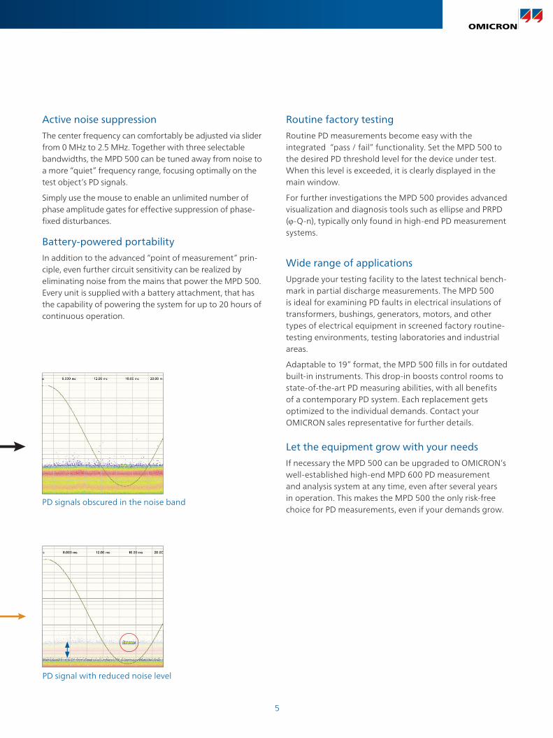
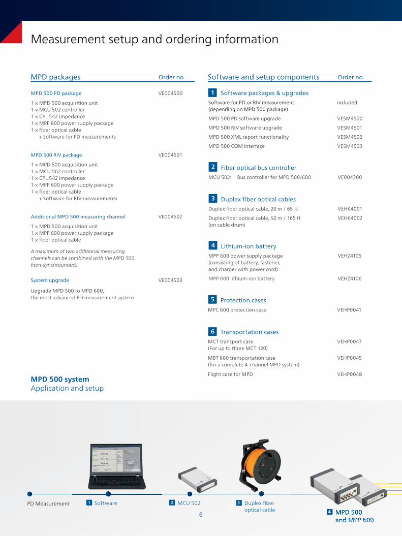
Active noise suppression
The center frequency can comfortably be adjusted via slider from 0 MHz to 2.5 MHz. Together with three selectable bandwidths, the MPD 500 can be tuned away from noise to a more “quiet” frequency range, focusing optimally on the test object’s PD signals.
Simply use the mouse to enable an unlimited number of phase amplitude gates for effective suppression of phase-fixed disturbances.
5
Battery-powered portability
In addition to the advanced “point of measurement” prin-ciple, even further circuit sensitivity can be realized by eliminating noise from the mains that power the MPD 500. Every unit is supplied with a battery attachment, that has the capability of powering the system for up to 20 hours of continuous operation.
C3’ C1
C2’
C2’
C3’
C3’ C1
C2’
C2’
C3’
C3’ C1
C2’
C2’
C3’
C3’ C1
C2’
C2’
C3’
PD signals obscured in the noise band
PD signal with reduced noise level
66
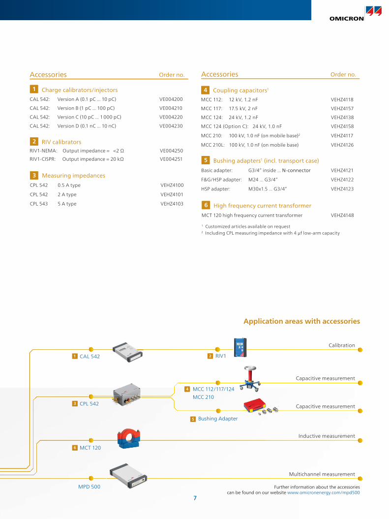
PD Measurement
Measurement setup and ordering information
Duplex fiber optical cable
MPD 500 systemApplication and setup
MPD 500and MPP 600
Software1 MCU 5022 3
4 MPD 500and MPP 600
4 MPD 500
MPD packages Software and setup components
MPD 500 PD package
1 × MPD 500 acquisition unit1 × MCU 502 controller1 × CPL 542 impedance1 × MPP 600 power supply package1 × fiber optical cable + Software for PD measurements
VE004500
MPD 500 RIV package
1 × MPD 500 acquisition unit1 × MCU 502 controller1 × CPL 542 impedance1 × MPP 600 power supply package1 × fiber optical cable + Software for RIV measurements
VE004501
Additional MPD 500 measuring channel
1 × MPD 500 acquisition unit1 × MPP 600 power supply package1 × fiber optical cable
VE004502
A maximum of two additional measuring channels can be combined with the MPD 500(non-synchrounous).
System upgrade
Upgrade MPD 500 to MPD 600, the most advanced PD measurement system
VE004503
Order no.Order no.
Duplex fiber optical cables
Duplex fiber optical cable, 20 m / 65 ft VEHK4001
Duplex fiber optical cable, 50 m / 165 ft (on cable drum)
VEHK4002
3
Lithium-ion battery
MPP 600 power supply package (consisting of battery, fastener, and charger with power cord)
VEHZ4105
MPP 600 lithium-ion battery VEHZ4106
4
2 Fiber optical bus controller
MCU 502: Bus controller for MPD 500/600 VE004300
Software packages & upgrades
Software for PD or RIV measurement(depending on MPD 500 package)
included
MPD 500 PD software upgrade VESM4500
MPD 500 RIV software upgrade VESM4501
MPD 500 XML report functionality VESM4502
MPD 500 COM interface VESM4503
1
Transportation cases
MCT transport case(For up to three MCT 120)
VEHP0047
MBT 600 transportation case(for a complete 4-channel MPD system)
VEHP0045
Flight case for MPD VEHP0048
6
Protection cases
MPC 600 protection case VEHP0041
5
77
Application areas with accessories
Further information about the accessories can be found on our website www.omicronenergy.com/mpd500
Capacitive measurement
Capacitive measurement
Inductive measurement
MCC 112/117/124
MCC 210
4
Bushing Adapter5
Calibration
Multichannel measurement
Accessories
Coupling capacitors1
MCC 112: 12 kV, 1.2 nF VEHZ4118
MCC 117: 17.5 kV, 2 nF VEHZ4157
MCC 124: 24 kV, 1.2 nF VEHZ4138
MCC 124 (Option C): 24 kV, 1.0 nF VEHZ4158
MCC 210: 100 kV, 1.0 nF (on mobile base)2 VEHZ4117
MCC 210L: 100 kV, 1.0 nF (on mobile base) VEHZ4126
4
Measuring impedances
CPL 542 0.5 A type VEHZ4100
CPL 542 2 A type VEHZ4101
CPL 543 5 A type VEHZ4103
3
Order no.
Charge calibrators/injectors
CAL 542: Version A (0.1 pC ... 10 pC) VE004200
CAL 542: Version B (1 pC ... 100 pC) VE004210
CAL 542: Version C (10 pC ... 1 000 pC) VE004220
CAL 542: Version D (0.1 nC ... 10 nC) VE004230
1
High frequency current transformer
MCT 120 high frequency current transformer VEHZ4148
6
Bushing adapters1 (incl. transport case)
Basic adapter: G3/4” inside ... N-connector VEHZ4121
F&G/HSP adapter: M24 ... G3/4” VEHZ4122
HSP adapter: M30x1.5 ... G3/4” VEHZ4123
5
1 Customized articles available on request2 Including CPL measuring impedance with 4 µf low-arm capacity
Accessories Order no.
CPL 542
CAL 542
3
1
MCT 1206
MPD 500
RIV12
RIV calibratorsRIV1-NEMA: Output impedance = <2 Ω VE004250
RIV1-CISPR: Output impedance = 20 kΩ VE004251
2
8
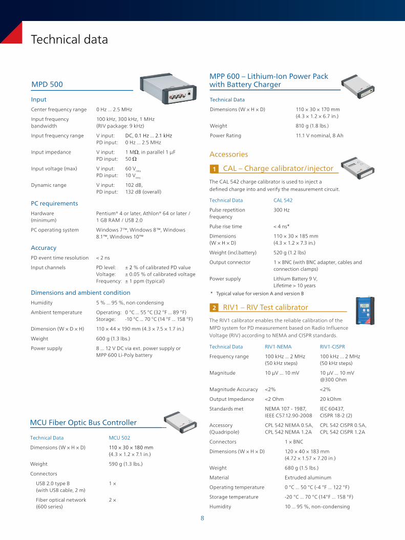
MPP 600 – Lithium-Ion Power Pack with Battery Charger
Technical Data
Dimensions (W × H × D) 110 × 30 × 170 mm(4.3 × 1.2 × 6.7 in.)
Weight 810 g (1.8 lbs.)
Power Rating 11.1 V nominal, 8 Ah
Technical data
CAL – Charge calibrator/injector1
The CAL 542 charge calibrator is used to inject a defined charge into and verify the measurement circuit.
Technical Data CAL 542
Pulse repetition frequency
300 Hz
Pulse rise time < 4 ns*
Dimensions (W × H × D)
110 × 30 × 185 mm (4.3 × 1.2 × 7.3 in.)
Weight (incl.battery) 520 g (1.2 lbs)
Output connector 1 × BNC (with BNC adapter, cables and connection clamps)
Power supply Lithium Battery 9 V,Lifetime > 10 years
MCU Fiber Optic Bus Controller
Technical Data MCU 502
Dimensions (W × H × D) 110 × 30 × 180 mm (4.3 × 1.2 × 7.1 in.)
Weight 590 g (1.3 lbs.)
Connectors
USB 2.0 type B(with USB cable, 2 m)
1 ×
Fiber optical network (600 series)
2 ×
Input
Center frequency range 0 Hz ... 2.5 MHz
Input frequency bandwidth
100 kHz, 300 kHz, 1 MHz(RIV package: 9 kHz)
Input frequency range V input: DC, 0.1 Hz ... 2.1 kHz PD input: 0 Hz ... 2.5 MHz
Input impedance V input: 1 MΩ, in parallel 1 µFPD input: 50 Ω
Input voltage (max) V input: 60 Vrms PD input: 10 Vrms
Dynamic range V input: 102 dB, PD input: 132 dB (overall)
PC requirements
Hardware (minimum)
Pentium® 4 or later, Athlon® 64 or later /1 GB RAM / USB 2.0
PC operating system Windows 7™, Windows 8™, Windows 8.1™, Windows 10™
Accuracy
PD event time resolution < 2 ns
Input channels PD level: ± 2 % of calibrated PD value Voltage: ± 0.05 % of calibrated voltage Frequency: ± 1 ppm (typical)
Dimensions and ambient condition
Humidity 5 % ... 95 %, non condensing
Ambient temperature Operating: 0 °C ... 55 °C (32 °F ... 89 °F)Storage: -10 °C ... 70 °C (14 °F ... 158 °F)
Dimension (W × D × H) 110 × 44 × 190 mm (4.3 × 7.5 × 1.7 in.)
Weight 600 g (1.3 lbs.)
Power supply 8 ... 12 V DC via ext. power supply or MPP 600 Li-Poly battery
MPD 500
Accessories
RIV1 – RIV Test calibrator2
The RIV1 calibrator enables the reliable calibration of the MPD system for PD measurement based on Radio Influence Voltage (RIV) according to NEMA and CISPR standards.
Technical Data RIV1-NEMA RIV1-CISPR
Frequency range 100 kHz ... 2 MHz (50 kHz steps)
100 kHz ... 2 MHz (50 kHz steps)
Magnitude 10 µV ... 10 mV 10 µV ... 10 mV @300 Ohm
Magnitude Accuracy <2% <2%
Output Impedance <2 Ohm 20 kOhm
Standards met NEMA 107 - 1987,IEEE C57.12.90-2008
IEC 60437, CISPR 18-2 (2)
Accessory(Quadripole)
CPL 542 NEMA 0.5A, CPL 542 NEMA 1.2A
CPL 542 CISPR 0.5A, CPL 542 CISPR 1.2A
Connectors 1 × BNC
Dimensions (W × H × D) 120 × 40 × 183 mm (4.72 × 1.57 × 7.20 in.)
Weight 680 g (1.5 lbs.)
Material Extruded aluminum
Operating temperature 0 °C ... 50 °C (-4 °F ... 122 °F)
Storage temperature -20 °C ... 70 °C (14°F ... 158 °F)
Humidity 10 ... 95 %, non-condensing
* Typical value for version A and version B

9
Technical Data CPL 542 CPL 543
Max. currents 0.5 A or 2 A 5 A
Frequency range (PD output)
20 kHz ... 5 MHz 29 kHz ... 5 MHz
Low-arm capacitance 30 μF (for 0.5 A version)120 μF (for 2 A version)
272 μF
Input connectors 2 × 4 mm terminals5
1 × GND2 × 4 mm terminals5
1 × GND
Output connectors 2 × BNC (PD & V),1 × BNC (TTL signal)
2 × BNC (PD & V)
Dimensions (W × H × D)
150 × 60 × 100 mm (5.9 × 2.4 × 4.0 in.)
150 × 60 × 100 mm (5.9 × 2.4 × 4.0 in.)
Weight 700 g (1.5 lbs.) 700 g (1.5 lbs.)
CPL – Measuring impedance3
The CPL quadripoles are an external measuring impedance for PD measurements. Both include an integrated 90 VPeak overvoltage protection device.
5 For connecting coupling capacitor
Technical Data Basic Adapter M24-F&G M30-HSP
Bushing manufacturer
Micafil / ABB F&G, HSP HSP (new types)
Measurement tap side(thread / connector)
G 3/4" insidefemale 4 mm / 0,2 in
M 24 insidemale4 mm / 0,2 in
M 30 × 1.5female 4 mm / 0,2 in
Diagnosis system side
N-Type female (incl. BNC adapter)
Connects to basic adapter
Connects to basic adapter
Surge arrester included – –
Bushing adapters5
A selection of combinable adapters for secure connections to bushings, delivered in a handy case.
Technical Data
Frequency Range (-6 dB) 80 kHz ... 40 MHz (0 mm gap)
Inner hole dimensions ø ~53.5 mm (2.11 in.)
Outer dimensions 114 × 154 × 62 mm(4.49 × 6.07 × 2.45 in.)
Ferrite core Split
Connector BNC, 50 Ohm, female
Weight 1.2 kg (2.65 lbs.)
Operating temperature -20 °C ... 55 °C (-4 °F ... 130 °F)
MCT 120 – High frequency CT6
The MCT 120 is a high-frequency current transformer (HFCT), which picks up partial discharge signals in moderate heights and at a safe distance from high-voltage.
MCC – Coupling capacitor4
The coupling capacitor connects the MPD 500/600 to the high-voltage test object. Different MCC coupling capacitors are available for various voltage levels. The MCC 112 and MCC 124 are designed for direct connection to the MPD 500/600. The MCC 210 is designed with a built-in quadripole measuring impedance with 4 µf low-arm capacity. Without the quadripole, it is available as MCC 210-L.
Technical Data MCC 112 MCC 117 MCC 124 MCC 210 / MCC 210-L
Upr8 (phase-to-ground) 12 kV 17.5 kV 24 kV 100 kV
CNominal 1.2 nF (± 20%) 2 nF (+/- 15 %) 1.2 nF (+/- 20%)Option C: 1.0 nF (+/- 15%)
1.0 nF (± 10%)
Withstand Voltage (1 min) 28 kV 38 kV 50 kV 120 kV
QPD < 2 pC @ 13.2kV < 2 pC @ 20.7 kV < 2 pC @ 26.4 kV < 1 pC @ 100 kV
Weight 4.5 kg / 9.9 lb 2.3 kg / 5.1 lb 6 kg / 13.2 lbOption C: 3.2 kg / 7.05 lb
10 kg / 22.1 lb
Dimensions (W × H × D) 182 × 158 × 182 mm /7.2 × 6.2 × 7.2 in
104 × 150 × 165 mm /4.1 × 5.9 × 6.5 in
182 × 238 × 182 mm /7.2 × 9.4 × 7.2 inOption C:150 × 219 × 150 mm /5.9 × 8.6 × 5.9 in
450 × 766 × 450 mm /17.5 × 30.15 × 17.5 in
Scope of delivery Adapter (TNC to BNC)BNC connection cable
Adapter (TNC to BNC)BNC connection cable
Adapter (TNC to BNC)BNC connection cable
BNC connection cable
1010
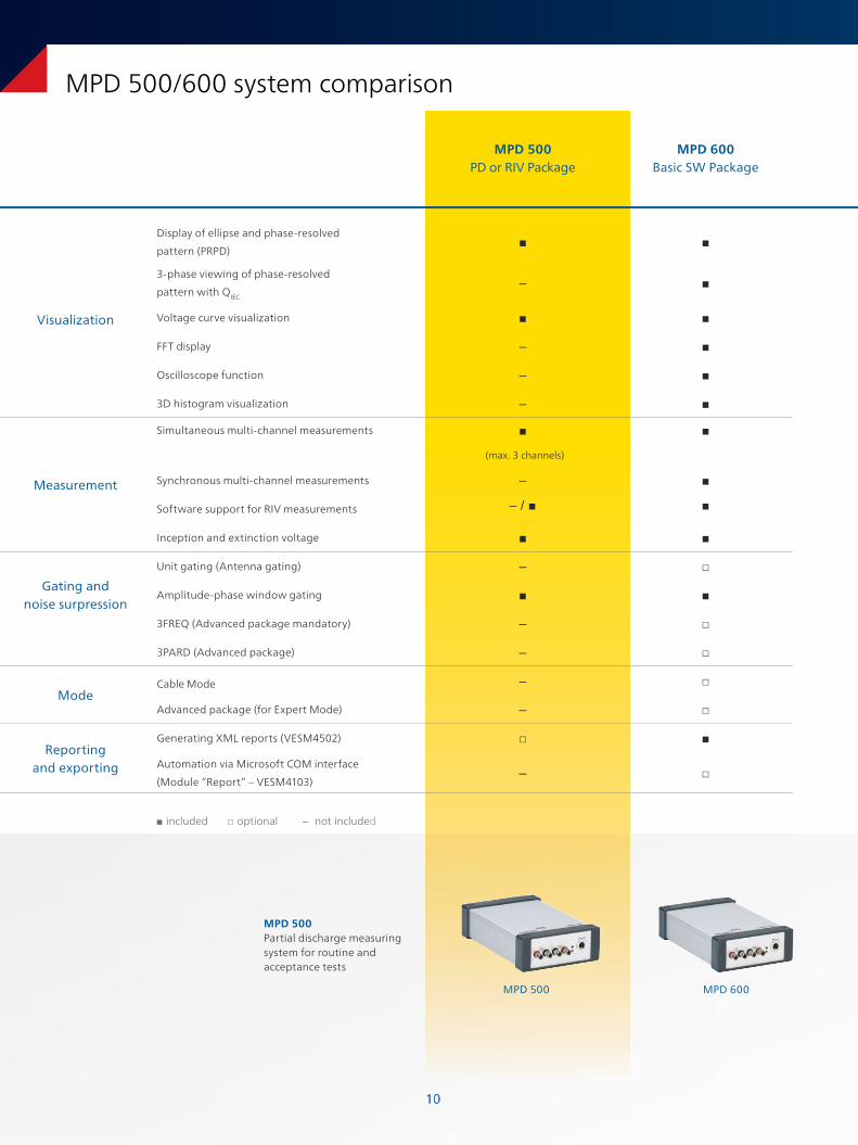
MPD 500/600 system comparison
MPD 500PD or RIV Package
MPD 600Basic SW Package
Visualization
Display of ellipse and phase-resolved
pattern (PRPD)
3-phase viewing of phase-resolved
pattern with QIEC
–
Voltage curve visualization
FFT display –
Oscilloscope function –
3D histogram visualization –
Measurement
Simultaneous multi-channel measurements
(max. 3 channels)
Synchronous multi-channel measurements –
Software support for RIV measurements – /
Inception and extinction voltage
Gating and noise surpression
Unit gating (Antenna gating) –
Amplitude-phase window gating
3FREQ (Advanced package mandatory) –
3PARD (Advanced package) –
ModeCable Mode –
Advanced package (for Expert Mode) –
Reporting and exporting
Generating XML reports (VESM4502)
Automation via Microsoft COM interface
(Module “Report” – VESM4103)–
included optional – not included
MPD 500Partial discharge measuring system for routine and acceptance tests
MPD 500 MPD 600
1111
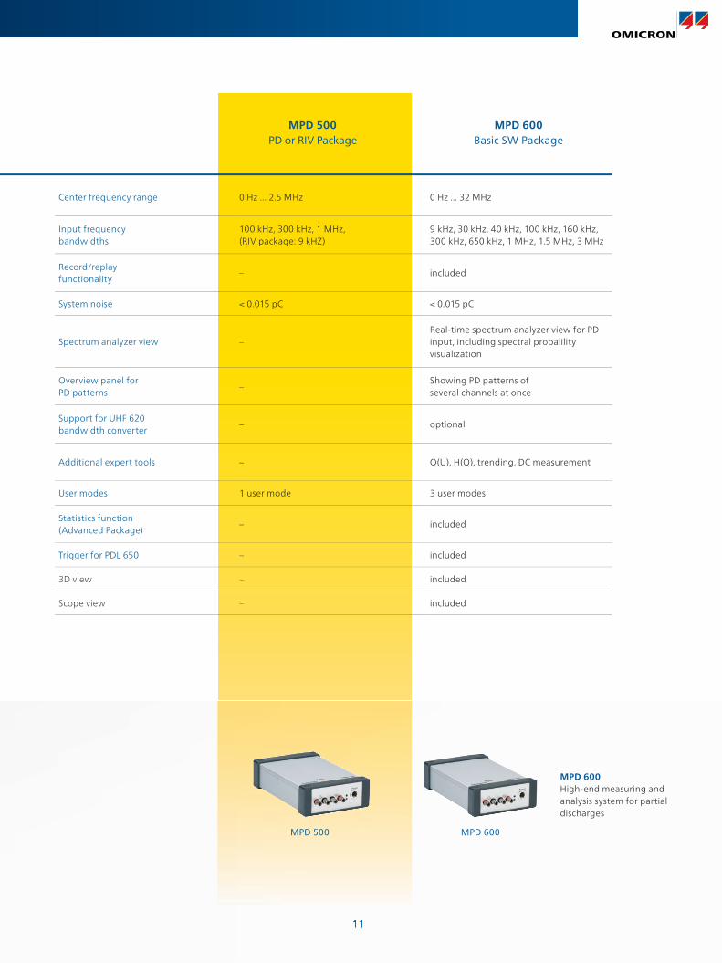
MPD 500 PD or RIV Package
MPD 600Basic SW Package
Center frequency range 0 Hz ... 2.5 MHz 0 Hz ... 32 MHz
Input frequency bandwidths
100 kHz, 300 kHz, 1 MHz,(RIV package: 9 kHZ)
9 kHz, 30 kHz, 40 kHz, 100 kHz, 160 kHz, 300 kHz, 650 kHz, 1 MHz, 1.5 MHz, 3 MHz
Record/replay functionality
– included
System noise < 0.015 pC < 0.015 pC
Spectrum analyzer view –Real-time spectrum analyzer view for PD input, including spectral probalility visualization
Overview panel for PD patterns
–Showing PD patterns of several channels at once
Support for UHF 620 bandwidth converter
– optional
Additional expert tools – Q(U), H(Q), trending, DC measurement
User modes 1 user mode 3 user modes
Statistics function (Advanced Package)
– included
Trigger for PDL 650 – included
3D view – included
Scope view – included
MPD 600High-end measuring and analysis system for partial discharges
MPD 600MPD 500

www.omicronenergy.com
The following publications provide further information on the solutions described in this brochure:
For more information, additional literature, and detailed contact information of our worldwide offices please visit our website.
MPD 600 Brochure
MPD 600High-end measurement and analysis system for partial discharges
OMICRON is an international company serving the electrical power industry with innovative testing and diagnostic solutions. The application of OMICRON products allows users to assess the condition of the primary and secondary equipment on their systems with complete confidence. Services offered in the area of consulting, commissioning, testing, diagnosis and training make the product range complete.
Customers in more than 150 countries rely on the company’s ability to supply leading-edge technology of excellent quality. Service centers on all continents provide a broad base of knowledge and extraordinary customer support. All of this together with our strong network of sales partners is what has made our company a market leader in the electrical power industry.
Subject to change without notice.© OMICRON L2669, December 2016