Embed Size (px)
Citation preview

MP Committee Meeting – April 12th, 2018 Agenda 1:00 PM at MCST
1. Brief review of Open Meetings Act 2. MP Process for Birth to Approval
a. Our Internal Process 3. Concrete MPs are in the process of being Reviewed by FHWA
a. MP 601.03.50 b. MP 603.02.10 c. MP 603.10.40 d. MP 604.02.40 e. MP 700.10.01 f. MP 709.04.40 g. MP 711.03.23 h. MP 714.03.30
4. MPs for Review: Kim Hoover: MP 688.02.20 - 3rd presentation to Committee. MP 688.03.20 - 3rd presentation to Committee. MP 700.00.00 - 1st presentation to Committee. Paul Farley / Steve Boggs: MP 307.00.50– (Edit possibly already resolved). Travis Walbeck/Vince Allison/John Crane: MPs that relate to PWL: MP 401.02.31 QC & Acceptance MP 401.07.20 Sampling Loose Asphalt Pavement Mixtures MP 401.07.21 Sampling Compacted Asphalt MP 401.07.22 Thickness of Asphalt Concrete Using Cores MP 401.07.23 Bond Strength MP 401.07.24 Pavement Macrotexture MP 401.07.25 Evaluation of Asphalt Pavements MP 401.13.50 Determination of PWL MP 700.00.05 Coring MP for Writing MPs MP 700.00.00 - PREPARING MATERIALS PROCEDURES Kelly Chapman/ Mike Mance MP 601.03.50

MP 688.02.20 ORIGINAL ISSUANCE: JANUARY 1979
3rd REVISION: MARCH 2017
WEST VIRGINIA DEPARTMENT OF TRANSPORTATION DIVISION OF HIGHWAYS MATERIALS CONTROL, SOILS AND TESTING DIVISION
MATERIALS PROCEDURE
GUIDE FOR CONTRACTOR'S AND FABRICATOR'S QUALITY CONTROL PLAN FOR PAINTING
1.0 SCOPE
1.1 This materials procedure shall serve as a guide for the design of the Contractor’s or Fabricator’s Quality Control Plan for surface preparation, application of coatings, and inspection procedures.
1.1.1 This procedure is applicable to structures that are being fabricated, erected, fully repainted, and/or zone painted.
2.0 REFERENCED DOCUMENTS
2.1 Reference to standard specifications and other standard procedures shall be the latest edition of the published document.
2.1.1 West Virginia Department of Transportation, Division of Highways Standard Specifications Road and Bridges 2017
a. 107-Legal Relations and Responsibility to Public b. 601-Structural Concrete c. 685-Bridge Cleaning d. 688-Field Painting of Metal Structures
2.1.2 Society for Protective Coatings (SSPC)
a. Monitoring and Controlling Ambient Conditions during Coating Operations. b. PA 1-Shop, Field and Maintenance Coating of Metals c. PA-2Procedure for Determining Conformance to Dry Coating Thickness
Requirements d. PA 17-Procedure for Determining Conformance to Steel Profile/Surface
Roughness/Peak Count Requirements. e. SP 13-Surface Preparation of Concrete f. SP 14-Industrial Blast Cleaning g. The Fundamentals of Cleaning and Coating Concrete 2001 h. Technology Guide 6: Guide for Containing Debris Generated During Paint
Removal Operations. i. Technology Guide 7: Guide to the Disposal of Lead-Contaminated Surface
Preparation Debris j. Technology Guide 16: Guide to Specifying and Selecting Dust Collectors

MP 688.02.20 ORIGINAL ISSUANCE: JANUARY 1979
3rd REVISION: MARCH 2017
2.1.3 International Organization for Standardization a. 8501- Preparation of Steel Substrates before Application of Paints and Related
Products - Visual Assessment of Surface Cleanliness. 2.2 Other SSPC, ASTM, ISO, or WV DOH Documents that may be applicable to the
application, surface preparation or inspection of applied coatings on any substrate, concrete or steel, not mentioned above.
3.0 REQUIREMENTS AND GUIDELINES
3.1 General Requirements 3.1.1 The Contractor or Fabricator shall provide and maintain a Quality Control System that
will give reasonable assurance that the paints have been applied in accordance with the specification requirements.
3.1.2 The Contractor or Fabricator shall conduct or have conducted inspections and tests required to substantiate that the paints have been applied in accordance with the specification requirements.
3.1.3 The Contractor's or Fabricator's Quality Control inspections and testing shall be documented and made available for review by the Engineer for the life of the contract.
3.2 Quality Control Plan
3.2.1 As stated in Specification 688, Section 688.2.5-Submittals, a Quality Control Plan shall be designed by the Contractor or Fabricator and submitted for acceptance/approval to the Engineer prior to commencement of the subject work. The plan shall clearly describe the methods by which the Quality Control Program will be conducted. Electronic submittals will be accepted. As a minimum, an acceptable plan should include the following:
a. Name of the company official responsible for Quality Control and for liaison with Division personnel.
b. Name of person(s) conducting the inspection.
c. Type of paint, name and address of the paint supplier, and the type and amount of thinner, if necessary, to thin or adjust the solvent balance of the paint as recommended by the manufacturer. Include a product data sheet for each product listed.
3.3 Surface Preparation 3.3.1 Appearance of the surface after blast cleaning shall correspond with the pictorial standard
as specified in the contract. Specify the instrument used for determining the height of the profile of the anchor pattern produced on the surface.
3.3.2 Specify the methods for determining the relative humidity, ambient temperature, temperature of the steel, and dew point.
3.4 Applied Coatings 3.4.1 Visually inspect the applied film for runs, sags, and other flaws.
3.4.2 Inspect for bubbles and pinholes by eight power (8x) magnification.

MP 688.02.20 ORIGINAL ISSUANCE: JANUARY 1979
3rd REVISION: MARCH 2017
3.4.3 Measure the dry film thickness of each coat of paint and, the accumulated total dry film thickness of the paint system. These measurements shall be taken and documented in accordance with SSPC PA-2.
3.5 A detailed plan of action regarding correction of flaws in the painted surface shall be included.
4.0 ENVIRONMENTAL CONDITIONS
4.1 The field Contractor shall submit to the Engineer his procedure for equipment cleanup, as well as his plan of action for any cleanup in the event of paint spillage.
5.0 FORMAT
5.1 The Quality Control Plan for Painting shall be submitted in the format shown in Attachment # 1.

MP 688.02.20 ORIGINAL ISSUANCE: JANUARY 1979
3rd REVISION: MARCH 2017 ATTACHMENT # 1
PROJECT INFORMATION State/Federal Project Number: Bridge Name/Number: District: County:
CONTRACTOR INORMATION Name: Address: Contact Person: Official responsible for Quality Control: Liaison with Division of Highways personnel:
COATING INFORMATION Areas to be coated: Name and address of coating supplier: Estimated quantity of material (in gallons) for each type of coating: Type and amount of thinner for each type of coating: Documentation that material has been approved by the Division of Highways, MCS&T:
INSPECTION Person(s) conducting the inspection: Areas to be inspected: Appearance of surface after blast cleaning: Instrument for measuring the height of the profile of the anchor pattern: Method for determining relative humidity: Ambient temperature: Temperature of the steel: Dew point: Magnification inspection: Wet film thickness gauge/Dry film thickness gauge: Dry film thickness measurement documentation:
CORRRECTIVE ACTIONS AND CLEAN UP Action regarding correction of coating flaws: Procedure for equipment cleanup Procedure for spillage cleanup:

MP 688.03.20 ORIGINAL ISSUANCE: JANUARY 1979
REISSUED: MARCH 2017
WEST VIRGINIA DEPARTMENT OF TRANSPORTATION DIVISION OF HIGHWAYS MATERIALS CONTROL, SOILS AND TESTING DIVISION
MATERIALS PROCEDURE
GUIDE FOR DEVELOPMENT OF THE CONTRACTOR'S ENVIRONMENTAL CONTROL PLAN FOR SPENT MATERIAL PRIOR TO PAINTING EXISTING STRUCTURES
1.0 SCOPE 1.1 This materials procedure shall be used as guidance for the development of the
Contractor's Environmental Control Plan for "Spent Material" prior to painting existing structures. This procedure is applicable for all structures having a coating system removed prior to field painting.
1.2 Spent Material”: This shall include material generated by surface preparation operations and shall be sampled and tested in accordance with the current revision of SSPC Guide 7, Guide to the Disposal of Lead-Contaminated Surface Preparation Debris. The Contractor shall, at the Contractor’s expense, select a laboratory that will sample and analyze the “Spent Materials”. The laboratory must be certified by the WVDEP, EPA, or by another state’s DEP-equivalent. Certification will be provided to the Engineer prior to the beginning of work. The waste transporter for both hazardous and non-hazardous waste will be listed on the Contractor’s Environmental Control Plan. The hazardous waste transporter named within the plan shall have a US EPA Identification Number.
2.0 REFERENCED DOCUMENTS
2.1 Reference to standard specifications and other standard procedures shall be the latest edition of the published document.
2.1.1 West Virginia Department of Transportation, Division of Highways Standard Specifications Road and Bridges
a. 107-Legal Relations and Responsibility to Public b. 601-Structural Concrete c. 685-Bridge Cleaning d. 688-Field Painting of Metal Structures
2.1.2 Society for Protective Coatings (SSPC) Technology Guides a. Technology Guide 6: Guide for Containing Debris Generated During Paint
Removal Operations. b. SSPC Technology Guide 7: Guide to the Disposal of Lead-Contaminated Surface
Preparation Debris c. SSPC Technology Guide 16: Guide to Specifying and Selecting Dust Collectors
2.2 Any SSPC, ASTM, ISO, AASHTO or WVDOH documents that may be applicable, not previously mentioned.

MP 688.03.20 ORIGINAL ISSUANCE: JANUARY 1979
REISSUED: MARCH 2017
3.0 ENVIRONMENTAL CONTROL PLAN
3.1 As stated in Specification 688, Section 688.2.5-Submittals, a Quality Control Plan shall be designed by the Contractor and submitted for acceptance/approval by the Engineer prior to commencement of the subject work. The plan shall clearly describe the methods by which the Contractor's Environmental Control Plan will be implemented. Electronic submittals will be accepted. As a minimum, an acceptable plan should include the following:
3.2 Name of the company employee who has been designated as the "Competent Person" for the project. A "Competent Person" shall be as defined in 29 CFR 1926.62. A "Competent Person" means one who is capable of identifying existing and predictable lead hazards in the surroundings or working conditions and who has authorization to take prompt corrective measures to eliminate them.
3.3 Level of containment and monitoring methods required by the project plans/specifications.
3.4 Name, type, size, and manufacturer of the abrasive to be used.
3.5 Name, type, manufacturer, and percentage of any additive included with the abrasive. 3.6 Specifics of the pollution control system proposed for the containment, collection,
storage, transport and disposal of the spent materials.
4.0 FORMAT
4.1 The Contractor is encouraged to explain in detail all items noted on Attachment # l. Additional information may be provided on separate documents attached to the Environmental Control Plan.
Hoover, Kimberly D� 9/1/17 9:22 AMComment [1]: Ron, do we want to add in a signature requirement for these docs?? Hoover, Kimberly D� 8/14/17 10:58 AMDeleted: .

MP 688.03.20 ORIGINAL ISSUANCE: JANUARY 1979
REISSUED: MARCH 2017
ATTACHMENT # 1
PROJECT INFORMATION State/Federal Project Number: Bridge Number/Name: District: County:
CONTRACTOR INFORMATION:
Name: Address: Contact: Contractor’s “Competent Person”:
ENVIRONMENTAL CONTROLS
Environmental containment level as per plans: Environmental containment monitoring methods:
ABRASIVES
Trade Name: Company: Recyclable: Size: Abrasive Additives: Trade Name: Company:
HAZARDOUS/NON-HAZARDOUS DISPOSAL
Waste Disposal Company: Address: Contact Person: Waste Transporter Company: Address; Contact person: Waste Disposal Site:
Non-Hazardous Material: Company: Address: Contact Person: Hazardous Material: Company: Address: Contact Person

MP 700.00.00 ISSUED: MAY 1965
REVISED: AUGUST 1974 REVISED: MARCH 2017
WEST VIRGINIA DEPARTMENT OF TRANSPORTATION DIVISION OF HIGHWAYS MATERIALS CONTROL, SOILS AND TESTING DIVISION
MATERIALS PROCEDURE
PREPARING A MATERIAL PROCEDURE
1.0 SCOPE
1.1 This procedure was established to illustrate a standard method, consistent and structured for creating, naming, indexing, and approval of Material Procedures (MPs).
2.0 REFERENCED DOCUMENTS
2.1 AASHTO § Standard Specifications for Transportation Materials, 35th Edition, 2015
2.2 Federal Highways Administration § Technical Advisory-March 2010
2.3 West Virginia Department of Transportation, Division of Highways, Standard Specifications Roads and Bridges 2017
3.0 NAMING MATERIAL PROCEDURES
3.1 The name and title of the MP shall give the user a clear idea of the material, test, sample, etc. that is addressed. The writer of the MP should revisit the title toward the end of the writing process to make sure that the title does in fact fit the subject.
4.0 NUMBERING AND INDEXING SYSTEM
4.1 All MP’s will conform to the numbering format described in Attachment # I. This format has been derived from AASHTO format.
4.2 The letters MP shall appear first, defining the document as a Material Procedure. 4.2.1 MP XXX.00.00
4.3 The first series of numbers corresponds with the WV DOH Standard Specifications Roads and Bridges section to which the procedure applies.
4.3.1 MP XXX.00.00 § 100– 199 General Provisions § 200– 299 Earthwork § 300– 399 Bases § 400– 499 Bituminous Pavements § 500– 599 Rigid Pavement § 600– 699 Incidental Construction § 700 – 799 Material Details
Hoover, Kimberly D� 3/17/17 9:43 AMComment [1]: These section numbers need confirmed
Hoover, Kimberly D� 4/3/18 9:15 AMComment [2]: Vince would like to change

MP 700.00.00 ISSUED: MAY 1965
REVISED: AUGUST 1974 REVISED: MARCH 2017
4.4 The second series of numbers corresponds to the WV DOH Standard Specifications Roads and Bridges sub-section to which the procedure applies.
4.4.1 MP 000.XX.00 4.5 The third series of numbers is defined by MCS&T as per the following:
4.5.1 MP 000.00.XX § 00 – 09 Field Sampling § 10 – 19 Pre-sampling (source or intermediate points § 20 – 29 Testing § 30 – 39 FUTURE § 40 – 49 Inspection § 50 – 59 Quality Assurance System § 60 – 69 Reporting (laboratory) § 70 – 79 Reporting (issuance under master control) § 80 – 89 FUTURE § 90 – 99 Miscellaneous
5.0 LAYOUT 5.1 Title
5.1.1 The title shall be concise. The title shall predict the content to the reader, and shall contain keywords that allow for easy electronic search.
5.2 Purpose 5.2.1 Section 1.0 will be Purpose. Within this section, the writer shall concisely state the
reason for the MP. Using as few words as possible and making sure that the reader is clear on why this MP exists.
5.3 Scope 5.3.1 Section 2.0 will be Scope. Within this section, the writer shall define the application of
the MP, and any categorical limits. Examples of these categorical limits include: Asphalt Mixtures, Superpave mix designs, Asphalt Mixtures with RAP, Concrete, Aggregates, Testing, and Sampling
5.4 Referenced Documents
5.4.1 Section 3.0 is for Referenced Documents. This section is intended to list technical references, standards, procedures, etc. from ASTM, AASHTO, West Virginia Division of Highways Standard Specifications, other Material Procedures, etc.
5.5 Creation of the Body of the MP
5.5.1 Sections and subsections of the MP should be carefully created. The information comprising these sections should be contemplated, discussed, and reviewed prior to approval and implementation.
Hoover, Kimberly D� 3/17/17 9:47 AMComment [3]: These numbers need confirmed
Hoover, Kimberly D� 3/20/17 11:30 AMComment [4]: Does this sentence need to stay??

MP 700.00.00 ISSUED: MAY 1965
REVISED: AUGUST 1974 REVISED: MARCH 2017
5.5.2 Typical sections and subsections may include topics such as: § General Information pertaining to the type of material. § Terminology/Definitions § Sampling/Field sampling § Testing methods/procedures § Equipment/testing apparatus § Documenting results and analysis § Calculations § Safety § Storage and Handling § Proper shipping
5.6 Testing Requirements
5.6.1 Calculations should cite technical references to document their origin. Cross referencing of specifications, special provisions, and other MPs is encouraged.
5.6.2 Tables, lists, and charts are encouraged and should be in a neat, orderly format. 5.6.3 Writing technique should be of a technical nature not narrative. Be concise using as few
words as possible to describe the procedure or method. Verboseness may lead to contradictions and opens the document to interpretation by the reader.
6.0 APPROVAL PROCESS Preliminary approval Process
The creating/approval process is as follows: The originator(s) create, edit, review and document the MP
The Group Supervisor reviews the MP
7.0 FINAL APPROVAL PROCESS
Once the MP has been reviewed and accepted within the MCS&T Division: The MP is submitted to the MCS&T Director for final review and approval.
The MP is then submitted to the WVDOH Deputy State Highway Engineer for review approval. The Deputy State Highway Engineer submits the MP to the Division Administrator at the Federal Highway Administration (FHWA) for review and approval. Once the FHWA has approved and returned the MP, it is signed by the MCS&T Director, and then given to the Administrative Secretary to be processed into the document management system and made available for distribution and use.
Hoover, Kimberly D� 3/20/17 11:35 AMComment [5]: Greg Bradford needs to review and then this doc will be edited for this section.

MP 700.00.00 ISSUED: MAY 1965
REVISED: AUGUST 1974 REVISED: MARCH 2017
Development and Review of Specifications Specification Review Checklist
Issue Yes No N/A Comments
Continuity of Thought and Logic
Are sentences and paragraphs limited to single ideas?
Is there an orderly arrangement of ideas throughout the specification?
Do requirements follow the natural sequence of the work?
Method of Presentation and Overall Organization
Is the five-part format (or agency equivalent) used?
Is the specification structured so that all information is easily accessible?
Are headings used to make it easier for readers to find information?
Language and Style
Is the language of the specification free of vague and ambiguous words and phrases?
Does the specification correctly use active voice and imperative mood?
Does the specification use shall and will correctly?
Is formatting consistent?
Is capitalization consistent (e.g., work vs. Work, engineer vs. Engineer)?
Is word choice consistent (e.g., pipe vs. conduit, select fill vs. gravel, reinforcing steel vs. rebar)?
Measurable Standards
Does the specification provide a clear description of what is to be measured for payment and the method of measurement?
Does the specification identify where and when the measurements will be made?
Can the inspector, using the specification as the standard of performance, determine whether the Contractor has complied with all of the specified work requirements?
Have escape clauses been avoided (e.g., requirements involving the "opinion of the Engineer")?
Sampling and Testing Requirements: Does the specification describe how acceptance will be determined? Are the specified tests necessary, or will product certification suffice?
Submittals: Does the specification describe the necessary submittal requirements? Are the submittal requirements realistic (i.e., are shop drawings really necessary or is catalog information sufficient)?
Coordinating Information and Requirements
Has the specification been closely examined for redundancies, contradiction, ambiguities, duplication, and overlap?
Are the specifications and drawings compatible?
Are drawings used where needed to amplify the work requirements?
PS&E Submittals
Are the current FHWA required standard provisions included as required by 23 CFR 633 Subpart A (i.e. FHWA-1273)?
Are the DBE participation goals identified (49 CFR Section 26)?
Are Buy America Act provisions included (23 CFR 635.410)?
Are the standard clauses on differing site conditions, suspensions of work, and significant changes in the character of the work included?
Do specifications satisfy all state, county, and local requirements and permit conditions?
Are the current Department of Labor Minimum Wage Rates included?
Are all proprietary products acceptable (ie. has a "finding in the public’s interest" been documented per 23 CFR 635.411)?
For any materials to be provided by the State or from sources designated by the State, has a public interest finding been obtained? Do the bidding documents identify the location and any other conditions to be met for the contractor to secure the materials?

MP 700.00.00 ISSUED: MAY 1965
REVISED: AUGUST 1974 REVISED: MARCH 2017
Specification Review Checklist
Issue Yes No N/A Comments
Are guarantee or warranty clauses included? (23 CFR 635.413)
Are alternative contracting procedures included? Is SEP-14 and/or SEP-15 approval needed?
Are any experimental features included in the project? If so, do you concur with their incorporation into the project and have you coordinated with the Division’s Technology Transfer Engineer?
Are items shown as participating in fact eligible for federal funding?
Are items shown as non-participating listed separately?
Are all force account items reasonable (23 CFR 635 Subpart B)?
Are itemized quantities/costs reasonable?

MP 307.00.50. ORIGINAL ISSUANCE:
NOVEMBER 1976 REVISED: DRAFT APRIL 2010
Page 1 of 6
WEST VIRGINIA DEPARTMENT OF TRANSPORTATION DIVISION OF HIGHWAYS
MATERIALS CONTROL, SOILS AND TESTING DIVISION
MATERIALS PROCEDURE
GUIDE FOR QUALITY CONTROL AND ACCEPTANCE PLANS FOR SUBGRADE, BASE COURSE, AND AGGREGATE ITEMS
1. PURPOSE
1.1 The purpose of this Materials Procedure (MP) is to establish minimum requirements for the Contractor’s Quality Control program and the Division’s Acceptance plan. It is intended that these requirements be used as a procedural guide in detailing the inspection, sampling, and testing deemed necessary to maintain compliance with the specification requirements.
1.2 To establish procedural guidelines for approval and documentation of a Master Quality Control Plan.
2. SCOPE
2.1 This MP outlines the quality control procedures for Aggregate items used in field operations and includes procedures for approving and using a Master and/or Project Specific Quality Control (QC) Plan. This MP will also aid in documentation and retention of the QC Plan in ProjectWise.
3. REFERENCED DOCUMENTS
3.1 Material Procedures:
§ MP 300.00.51, Procedural Guidelines for Maintaining Control charts for Aggregate Gradations
§ MP 700.00.54, Procedure for Evaluating Quality Control Sample Test Results with Verification Sample Test Results
§ ML-25, Procedure for Monitoring the Activities Related to Sieve Analysis of Fine and Coarse Aggregate
§ MP 700.00.06 Aggregate Sampling Procedures

MP 307.00.50. ORIGINAL ISSUANCE:
NOVEMBER 1976 REVISED: DRAFT APRIL 2010
Page 2 of 6
4. GENERAL REQUIREMENTS
4.1 The Contractor shall provide and maintain a quality control system that will provide reasonable assurance that all materials and products submitted to the Division for acceptance will conform to the contract requirements whether manufactured or processed by the Contractor or procured from suppliers, subcontractors, or vendors. The contractor shall perform or have performed the inspections and tests required to substantiate product conformance to contract document requirements and shall also perform or have performed all inspections and tests otherwise required by the contract. The Contractor's quality control inspections and tests shall be documented and shall be available for review by the Engineer throughout the life of the contract. The Contractor shall maintain standard equipment and qualified personnel as required by the Specifications to assure conformance to contract requirements. Procedures will be subject to the review of the Division before the work is started.
5. QUALITY CONTROL PLAN
5.1 The contractor shall prepare a Quality Control Plan (QC Plan) detailing the type and frequency of inspection, sampling, and testing deemed necessary to measure and control the various properties of materials and construction governed by the Specifications. As a minimum, the sampling and testing plan should detail sampling location, sampling techniques, and test frequency to be utilized. Attachment #2 shows an example QC Plan. Quality control sampling and testing performed by the Contractor may be utilized by the Division for acceptance.
5.1.1 A QC Plan must be developed by the Contractor and submitted to the Engineer prior to the start of construction on every project. Acceptance of the QC Plan by the Engineer will be contingent upon its concurrence with these guidelines.
5.2 As work progresses, an addendum(s) may be required to a QC Plan to keep the QC program current. Personnel may be required to show proof of certification for testing.
5.3 The Quality Control Plan shall include:
5.3.1 Name: The name of the company official responsible for the quality control program. A phone number and an email address for contacting this individual shall be included in the cover letter.
5.3.2 Personnel: The company will provide a WVDOH certified Aggregate Sampler and Technician, either from the company or a consultant testing firm.
5.3.3 Items: List of Aggregate items to be controlled by QC Plan. Bradford, Greg F� 12/19/16 11:28 AM
Deleted:

MP 307.00.50. ORIGINAL ISSUANCE:
NOVEMBER 1976 REVISED: DRAFT APRIL 2010
Page 3 of 6
5.3.4 Sampling and Testing Plan: As a minimum, the sampling and testing plan should detail sampling locations, test methods, and test frequencies to be used (Attachment 1). To facilitate the Division of Highway’s monitoring activities, which are described in Section 7.1, all completed gradation samples must be retained by the Contractor until further disposition is designated by the District Materials Supervisor. The QC Plan should state where and how these samples will be maintained. Applicable sections of Materials Letter (ML) 25 should be used for guidance.
5.3.5 Testing Facility: The plan should state the specific location where the samples(s) will be tested and retained.
5.3.6 Documentation Plan: The method by which the Contractor will document and distribute test results must be described.
5.3.7 Forms and Distribution: Approved processing forms furnished by the Division will be used to record the test data. Gradation tests will be recorded on Form T300. The laboratory reference number will always start with a "C" for all quality control samples taken and tested by the Contractor. One copy of each completed form should be retained by the Contractor until the work is completed and accepted. A signed copy of the test data is to be delivered to the District Materials Supervisor. To be an effective quality control function, tests must be completed and results distributed in a regular and timely manner. The plan, therefore, must state what action will be taken in the event that testing and reporting are not completed in a reasonable period of time - preferably within 72 hours after the sample is taken.
5.3.8 Control Charts: The specifications require the plotting of gradation test results on control charts using the moving average concept as described in MP 300.00.51. The QC Plan should state where and how the charts will be maintained and made available to Division personnel. These charts are part of the Division's acceptance procedures and must be available to the Division when the project is completed or at the request of the Division personnel. At the contractor's request, the requirement of Control Charts may be waived on a per project Basis. The Contractor will submit a written request to the Division asking that the Control Charts be waived. Division will make a determination based on the size of the project and the number of gradation tests required.
5.3.9 Disposition of Non-Specification Material: A detailed plan of action providing for the immediate notification of all parties involved in the event that nonconforming situations are detected.
5.3.10 Types of QC Plans
5.3.10.1 QC Plans which are intended for use on more than one project shall be defined as Master QC Plans. Section 6.1 outlines the procedures for Master QC Plan submittal and approval.
Bradford, Greg F� 12/19/16 11:28 AMFormatted: Keep with next, Keep linestogether
Bradford, Greg F� 12/19/16 11:28 AMDeleted:

MP 307.00.50. ORIGINAL ISSUANCE:
NOVEMBER 1976 REVISED: DRAFT APRIL 2010
Page 4 of 6
5.3.10.2 QC Plans which are intended for use on a single project shall be defined as Project Specific QC Plans. Project Specific QC Plans shall contain a cover letter which includes the following: project description, Contract Identification Number (CID#), and Federal and/or State Project Number.
5.3.10.3 A contractor may submit a Master QC Plan instead of a Project Specific QC Plan.
5.3.10.4 Once any QC Plan is approved for a project, the key date shall be entered in Site Manager by the appropriate District Materials personnel. The first date entered shall be the date the Project QC Plan letter is received. The second date shall be when the district approves the QC Plan for use on the project.
6. MASTER QUALITY CONTROL PLAN
6.1 The intent of a Master QC Plan is to facilitate the approval process in a more uniform manner. Master QC Plans can be submitted to the Division by the Contractor when their work load in a given District is routinely repetitive for the year.
6.2 The Contractor shall submit a Master Aggregate Items QC Plan yearly to each District in which they have work (see Attachment #2). If the Contractor does not have work in a given District for the year, then a Master Field QC Plan shall not be submitted to that District.
6.3 The District will review the submitted Master QC Plans to see if they meet the requirements for an Aggregate Items QC Plan as per section 5.3 and assign a laboratory reference number to the Master QC Plan upon approval for future referencing. The District will acknowledge approval of each Master QC Plan to the Contractor by letter (see Attachment #3), which will include the laboratory reference number and a copy of the approved Master QC Plan. This will then be scanned and placed in ProjectWise under the appropriate District’s Org for that Contractor and/or Producer/Supplier.
6.4 Once a project has been awarded, if a Contractor elects to use the approved Master Aggregate Items QC Plan on that project, the Contractor shall submit a letter requesting to use the Master QC Plan for that project. This letter must be on the Contractor’s letterhead paper, be addressed to the District Engineer/Manager or their designee, and contain the following information: project number, CID#, project description, type of QC Plan, and the laboratory reference number for the Master QC Plan. (See attachment #4.)
6.5 The District shall review the referenced Master QC Plan to ensure it covers all items in the project. If the referenced Master QC Plan is found to be insufficient for some items on the project, the District shall request the Contractor to submit additional information for quality control of those items as an addendum on a project specific basis. When the District is satisfied with the QC Plan for this project, a letter shall be sent to the Contractor acknowledging approval (see Attachment #5), with the following attached: the contractor’s project QC Plan request letter and the Master QCP approval letter. This shall then be placed in the project’s incoming-mail mailbox in ProjectWise.
Bradford, Greg F� 12/19/16 11:25 AMDeleted: <#>
Bradford, Greg F� 1/23/17 3:33 PMFormatted: Normal 2
Bradford, Greg F� 12/19/16 11:26 AMDeleted:

MP 307.00.50. ORIGINAL ISSUANCE:
NOVEMBER 1976 REVISED: DRAFT APRIL 2010
Page 5 of 6
6.6 A Master QC Plan that has been approved for project use shall be good for the duration of that project.
6.7 For the use of Division Personnel, the District approval letter for this project must state the ProjectWise link to the referenced Master QC Plan for that Contractor. For example, WVDOT ORGS > District Organization #> Materials > Year>Master QC Plans, etc.
6.8 The Master Aggregate items QC Plan shall be valid for the duration of one calendar year beginning on January 1st and ending on December 31st.
7. ACCEPTANCE PLAN
7.1 The specifications state that acceptance (verification) sampling and testing is the responsibility of the Division. Quality Control tests are the responsibility of the Contractor. Acceptance activities (sampled and tested at the frequency given in Section 7.1.2) may be accomplished by conducting verification sampling and testing completely independent of the Contractor and, in some cases, by witnessing tests performed by the Contractor, or by a combination of the two. The following guidelines provide a system which should result in sufficient confidence in the Contractor's documentation of his Quality Control operations to permit acceptance of the material in accordance with the procedure set forth in the Specifications.
7.1.1 Review all information supplied by the Contractor on the Quality Control Plan. Note in particular the qualifications of the sampler, tester, the location, and other qualifying statements about the testing facility. In the event the testing facility is such that little qualifying information is supplied or known, this facility should be visited prior to the work and reviewed relative to the availability, type, and suitability (including applicable calibration checks) of the testing equipment. This information should be documented and kept available at the District Materials Section.
7.1.2 Sample and test for applicable items completely independent of the Contractor at a frequency equal to or greater than ten (10) percent of the frequency for testing given in the approved Quality Control Plan. Witnessing the Contractor's sampling and testing activities may also be a part of the acceptance procedure, but only to the extent that such tests are considered "in addition to" the ten (10) percent independent tests.
7.1.3 Plot the results of gradation tests performed by the Division on the Contractor's quality control charts with a red circle, but do not include these values in the moving average. When the Contractor's tests are witnessed, circle the Contractor's test result on the control chart with red. These values are used in the moving average calculations. The laboratory number will always start with an "M" for all acceptance (verification) samples taken and tested in this manner by the Division, and will always start with a "0" for all of the Contractor's tests which are witnessed by the Division. Evaluate the results of acceptance (verification) tests, whether performed or witnessed by the Division, in accordance with MP 700.00.54.
7.1.4 If the evaluation indicates similarity with the quality control test, the control chart will be considered acceptable to that point.
Bradford, Greg F� 12/19/16 11:26 AMDeleted: Page Break
Bradford, Greg F� 12/19/16 11:26 AMDeleted: ... [1]

MP 307.00.50. ORIGINAL ISSUANCE:
NOVEMBER 1976 REVISED: DRAFT APRIL 2010
Page 6 of 6
7.1.5 If dissimilarity is determined, an immediate investigation will be conducted in an effort to determine the cause. Until the situation is resolved, any samples held in accordance with ML 25 will be retained and may be used in whatever manner deemed appropriate during the investigation.
7.2 Implement ML-25 for aggregate gradations.
Ronald L. Stanevich, PE Director Materials Control, Soils & Testing Division
RLS : Fm Attachments

MP 307.00.50. ORIGINAL ISSUANCE:
NOVEMBER 1976 REVISED: DRAFT APRIL 2010
ATTACHMENT #1 Page 1 of 2
GUIDELINES FOR CONTRACTOR’S QUALITY CONTROL
Item Description Property Minimum Frequency
207 Subgrade
Gradation One (1) sample per day of placement. Note 1
Atterburg Limits
From an approved aggregate source: one (1) test at the beginning of placement and then each 10,000 tons. Not from an approved aggregate source a minimum of one (1) test per 6 days placement.
212 Select Material for Backfill Gradation Minimum of one (1) sample
per day of Placement. Note 1
307 Crushed Aggregate
Gradation One (1) sample per each one-half (1/2) day placement. Note 1
Atterburg limits One(1) test at the beginning of placement and then each 10,000 tons thereafter
Other tests as requested by the Division or required by
the contract documents: percent crushed particles,
unit weight, etc.
As requested by the Division or required by the contract documents.
307 aggregate Shoulder Course for Resurfacing Projects
Gradation One (1) sample per day of placement. Note 1
Atterburg limits One(1) test at the beginning of placement and then each 10,000 tons thereafter
Other tests as requested by the Division or required by
the contract documents: percent crushed particles,
unit weight, etc.
As requested by the Division or required by the contract documents.

MP 307.00.50. ORIGINAL ISSUANCE:
NOVEMBER 1976 REVISED: DRAFT APRIL 2010
ATTACHMENT #1 Page 2 of 2
GUIDELINES FOR CONTRACTOR’S QUALITY CONTROL
604 Class 1 Aggregate Gradation Minimum of one (1) sample
per day of placement. Note 1 606 Aggregate for
Underdrain Gradation Minimum of one (1) sample per day of placement. Note 1
609 Bed Course Material Gradation Minimum of one(1) sample per
day of placement. Note 1
626 Aggregate
Gradation Minimum of one (1) sample per day of placement. Note 1
Atterburg Limits
From an approved aggregate source: one (1) test at the beginning of placement and then each 10,000 tons. Not from an approved aggregate source a minimum of one (1) test per 6 days placement.
636 Aggregate
Gradation One (1) sample per each one-half (1/2) day of placement. Note 1: Note 2
Atterburg Limits One (1) test at beginning of placement and then each 10,000 tons thereafter. Note 2
Note 1: In the event project activities are such that relatively small quantities of material are being placed per placement date, and to prevent over sampling, the Engineer may approve the following alternate sampling method : A minimum of One (1) sample per six (6) consecutive days shall be taken to represent up to each 170 cubic yards(250 tons). Sampling is to be done on the first day of aggregate placement. In this case the sample shall be taken at a random time and place Note 2: When Aggregate for maintaining traffic is not to be part of any succeeding base or pavement course, the appropriate aggregate size shall be determined by the Engineer. If the aggregate is from an approved source, then it shall be accepted by visual inspection. If the Contractor elects to use aggregate from an unapproved source, test results shall be provided to show that the liquid limit and plasticity index meet the requirements in Table 704.6.2B

MP 307.00.50. ORIGINAL ISSUANCE: NOVEMBER 1976 REVISED: DRAFT APRIL 2010 ATTACHMENT #2 Page 1 of 2
*** EXAMPLE GUIDE FOR AGGREGATE ITEMS QUALITY CONTROL PLAN ***
The Acme Company 20 First St. Somewhere, WV XXXXX
Mr/./Ms/Mrs. _______________________ WV Department of Highways District ___ Engineer/Manager __________, WV RE: “year” Master Aggregate Items QC Plan DISTRICT: _____ Dear Mr./Ms/Mrs. ___________________ We are submitting our Master QC Plan for Aggregate Items, developed in accordance with the (year) WVDOH Standards and Specifications, (year) WVDOH Supplemental specifications, MP300.00.51, MP 700.00.54, ML-25, and AASHTO Testing standards.
The Quality Control Program is under the direction of __________________ . He/She can be contacted by telephone number _____________, email __________________ and/or in person. 1.) All testing will be performed by qualified personnel as per WVDOH Specification Section 106 Control of Materials. Proof of personnel certification shall be provided to WVDOH inspectors upon request. 2.) Specify items to be controlled and the methods by which each item will be tested (For example: 207, 307…etc) Attachment #1 summarizes the different materials, minimum frequencies, and the appropriate test procedure or method for controlling each material. - 207 Items - 212 Items -307 Crushed Aggregate Items - ETC>>>>> 3.) List the location (address) and lab where testing will be performed. 4.) State the method and means by which that Contractor will document and distribute test results. 5.) State what forms will be used for tests the time frame for completing testing and distributing of test information to District Materials.

MP 307.00.50. ORIGINAL ISSUANCE: NOVEMBER 1976 REVISED: DRAFT APRIL 2010 ATTACHMENT #2 Page 2 of 2
6.) Specify in the QC Plan where and how the charts will be maintained and made available to Division/District personnel. Control Charts will use the moving average concept as described in MP 300.00.51. 7.) Specify a plan of action providing for immediate notification of all parties involved in the event that nonconforming material situations are detected.
Yours Truly,
_____________________________ Company Representative, Title

MP 307.00.50. ORIGINAL ISSUANCE: NOVEMBER 1976 REVISED: DRAFT APRIL 2010 ATTACHMENT #3 Page 1 of 1
******** WVDOH LETTERHEAD ********
ACME Company 20 First St. SOMEWHERE, WV ##### RE: Aggregate Items Master QC Plan Description: (Year) Construction Season Dear Sir/Madam,
Your Master Aggregate Quality Control Plan (M#-#####) for _________________has been reviewed and found to be acceptable for the following items:
- 207 Aggregate Items - 212 Aggregate Items - 307 Aggregate Items - ETC As work progresses throughout the season, an addendum(s) may be required
to this QCP to keep the QC program current. Also note that personnel may be required to show proof of certification for testing. Please use Lab Reference # M#-###### when corresponding about this QC plan. Please make sure that all appropriate personnel have a copy of this plan in their possession.
Very Truly Yours,
_____________________ Title

MP 307.00.50. ORIGINAL ISSUANCE: NOVEMBER 1976 REVISED: DRAFT APRIL 2010 ATTACHMENT #4 Page 1 of 1
******** EXAMPLE ********
THE ACME COMPANY INC. 20 First St. Somewhere, WV XXXXX
Mr./Ms/Mrs _______________________ WV Department of Highways District ___ Engineer/Manager __________, WV Subject: Aggregate Items QC plan For project Fed. Project No _____________________________ State Project No. __________________________ Contract ID No. __________________________ Description _____________________________ Dear Mr./Ms/Mrs. _____________________, We would like to use our approved Aggregate Items Master Quality Control Plan, reference number ______________ for the project referenced above. We feel that all items on the referenced project are covered by the Master Quality Control Plan for Aggregate Items. The QC Plan is under the direction of ___________________________________, ________________(title), and will be the Company’s contact representative to the Department of Highways District Materials and Construction Departments. He/She can be contacted in person at the project, by telephone ________________________________ or at email account _________________.
Very Truly yours, ______________________ Company Representative

MP 307.00.50. ORIGINAL ISSUANCE: NOVEMBER 1976 REVISED: DRAFT APRIL 2010 ATTACHMENT #5 Page 1 of 1
*************** WVDOH LETTERHEAD **************
THE ACME COMPANY INC. 20 First St. Somewhere, WV XXXXX RE: _____ Aggregate Items QC Plan Project CID#: ######## Fed/State Project #: ####- ## - ####.## Description: Falling Slide County: XXXXXXX Dear Sir/Madam, Your request to use your Master Aggregate Items Quality Control Plan (M# - ######) for Aggregate Items on the project referenced above, has been reviewed and found to be acceptable for the following items:
- 207 Aggregate Items - 212 Aggregate Items - 307 Aggregate Items - ETC As work progresses throughout this project an addendum(s) may be required
to this QCP to keep the QC program current. Please use M# - ###### when corresponding about this QC plan. Also note that personnel may be required to show proof of certification for testing. Please make sure that all appropriate personnel have a copy of this plan in their possession.
For Division/District use
The Master Quality Control Plan can be reviewed in ProjectWise at this Link: WVDOT ORG>D0#>year>MASTER QC PLANS>Contractors or Plant>Contractor Name>Name of Quality Control Plan
Very Truly Yours, ________________________________ Whoever

MP 401.02.31 JANUARY 2015 PAGE: 1 OF 11
WEST VIRGINIA DEPARTMENT OF TRANSPORTATION
DIVISION OF HIGHWAYS MATERIALS CONTROL, SOILS AND TESTING DIVISION
MATERIALS PROCEDURE
___________________________________________________________________________
GUIDE FOR QUALITY CONTROL AND ACCEPTANCE REQUIREMENTS FOR ASPHALT MIXTURES ON SPECIFIED INTERSTATE AND EXPRESSWAY PROJECTS
___________________________________________________________________________ 1. PURPOSE 1.1 Provide a method for daily monitoring and quality assurance of Superpave and
Marshall asphalt mixtures.
1.2 Provide guidelines for adequate acceptance plans.
1.3 Provide plant personnel with criteria upon which to base decisions of continuing or ceasing plant production.
1.4 Provide field personnel with criteria upon which to base decisions of accepting or rejecting of material.
1.5 Provide an equitable and uniform method for determining compliance or non-compliance with project specifications, and calculating corresponding price adjustments.
2. SCOPE
2.1 This acceptance procedure shall be applicable to all large quantity Superpave and Marshall asphalt mixture types relative to compliance with Job Mix Formula (JMF) acceptance limits as specified in the governing specifications.
3. DEFINITIONS
3.1 Job Mix Formula – The specification for a single mix produced at a single plant. This mix may be used on a single project or on multiple projects if the basic design criteria (design compaction level and PG Binder grade) are the same.
3.2 Lot – The amount of material that is to be judged acceptable or unacceptable on the basis of a sample comprised of the specified number of test results. For acceptance decisions in this materials procedure a normal Lot size is 2,500 tons (2270 Mg) unless operational conditions or project size dictate otherwise.
3.3 Sublot – Equal subdivisions of the Lot used for stratified random sampling and testing. For this materials procedure a normal Sublot size is 500 tons (450 Mg) unless operational conditions or project size dictate otherwise.
3.4 Field Design Verification Samples and Tests - Those samples taken and tests performed by the contractor to verify that a mix design can be produced within the

MP 401.02.31 JANUARY 2015 PAGE 2 OF 11
____________________________________________________________________________
limits of the criteria set forth by this Materials Procedure. These samples are taken during the initial use of each mix design or whenever circumstances described in this MP require a new field design reverification. These samples should not be confused with the Division verification samples that are used for acceptance purposes.
3.5 Quality Control Samples and Tests - Those samples taken and tests performed by the Producer/Contractor to monitor and control the production of this product.
3.6 Verification Samples and Tests - Those samples taken and tests performed by the Division to determine specification compliance of the contractor’s quality control testing.
3.7 Acceptance Samples and Tests – Those samples taken and tests performed by the Division that are used to determine whether or not a price adjustment is required on a Lot of asphalt pavement.
4. DOCUMENTATION
4.1 The Contractor shall maintain adequate records of all testing and records of any production changes required to control their product. The records shall indicate the nature and number of observations made, the number and type of deficiencies found, and the nature of corrective action taken. The Contractor’s documentation procedures will be subject to the review and approval of the Division at any time during the progress of the work being performed.
4.1.1 All asphalt mixture component materials shipped to the plant must have proper documentation which identifies the type and source of each material. This information shall be made accessible to the Division for review at any time.
4.2 Forms and Distribution: All test data shall be documented on forms provided by the Division. The original copy of the form shall be delivered to the District Materials Supervisor. One copy of each completed form is to be retained by the contractor until the project is completed. Testing shall be conducted using only the approved test methods listed in Section 401.5 of the Standard Specification unless specified otherwise in this MP or other contract documents. Asphalt content and gradation test results shall be recorded on form T417. Mix design property test results shall be recorded on form T419 for Superpave mixtures and form T406 for Marshall mixtures.
4.3 When the Contractor produces materials or products that do not conform to the requirements of the contract documents, the Contractor shall take prompt action to correct the resulting conditions, and to prevent undesirable conditions that may result. The Contractor shall establish a detailed plan of action regarding the disposition of non-specification material.
4.3.1 In the event that non-specification material is incorporated into the project, the Contractor shall notify the Division immediately and shall supply to the Division a detailed description of the non-specification materials and where they were placed.

MP 401.02.31 JANUARY 2015 PAGE 3 OF 11
____________________________________________________________________________
The Division shall then evaluate the effects of inclusion of the non-specification material and act accordingly. Refer to MP 401.07.25 for additional guidance.
4.3.2 All applicable QA/QC forms and worksheets can be found on the MCS&T web page at the following link:
http://www.transportation.wv.gov/highways/mcst
5. JOB MIX FORMULA FIELD DESIGN VERIFICATION
5.1 For each paving season, during the initial production of each JMF, a field design verification shall be conducted during the first days of plant production for the purpose of demonstrating that the mix can be produced within the specified tolerances set forth in this MP.
5.2 This field design verification shall consist of a randomly selected asphalt mixture sample taken in accordance with the AASHTO T168 truckbed sampling method for each 750 tons (680 Mg) delivered to the project with a maximum of three samples in one day. A minimum of three samples are required for verification, however, up to three additional samples are required if none of the first three individual samples and the average of the three samples are completely within the tolerance limits of Table-A.
5.2.1 If the Contractor desires, field design verification sampling can be moved to the roadway to coincide with the Division’s sampling rate as long as samples are taken at the same time and location as the Division’s verification samples are taken as described in the sampling materials procedure, MP 401.07.20. When roadway samples are taken for field design verification they will be taken at a rate of one sample for every 500 ton (450 Mg) delivered to the project with a maximum of four samples (if needed) in one day. If the roadway samples are only used for percent asphalt and gradation analysis then a separate sample taken at the same production rate shall be taken from the truckbed at the plant for volumetric testing. If the roadway sampling method is used skip to Section 5.5.
5.3 Use a random number table or calculator that generates random numbers to select
the tonnage at which to sample. Do not take a sample within the first 100 tons (90 Mg) of production during the day unless it consists of mixture that remained in the storage silo in accordance with WVDOH specification from the previous production day. For all new production material for the day take the first sample from the first loaded truck following the truck containing the 100th ton (90th Mg) produced.
5.3.1 Example sampling calculations: 750 tons x random number = tonnage to sample
First Sublot Sample = 750 x .215 (random number) = 161
First sample would be taken from the truck that contains the 161st ton of mixture produced for the day.
Second Sublot Sample = 750 x .521 (random number) = 391

MP 401.02.31 JANUARY 2015 PAGE 4 OF 11
____________________________________________________________________________
Second sample would be taken from the truck that contains the 391st ton from this second Sublot after the first 750 tons; therefore the tonnage would be 750 + 391 = 1141.
5.4 When a Sublot is going to represent less than 750 ton (680Mg) but at least 200 tons (180 Mg) estimate the tonnage to determine the random sample tonnage.
5.5 Do not conduct field design verification testing on a sample that represents less than 200 tons (180 Mg). Wait until the next production day to take the next sample, and proceed as described in Section 5.8.
5.6 Samples used for gradation analysis during the verification process shall be obtained from the asphalt ignition oven samples (AASHTO T308). For each mix design, an asphalt content correction factor and any required gradation correction factors (due to aggregate breakdown) shall be determined in accordance with AASHTO T-308. This correction information, along with the ignition oven model and identification number, shall be submitted to the District Materials Section on Form T416 prior to beginning the verification process each year and anytime thereafter that new correction factors are determined.
5.7 The maximum specific gravity of each test sample shall be calculated and the average value of the test samples for each day shall be presented to the DOH for use as the target maximum density of the mixture for determining the density of the project cores taken on the same day. In the event that both QC testing and field design verification are performed during the same day, use the average of all maximum specific gravity test results.
5.8 In the event that less than 200 tons (180 Mg) of mixture are produced then field design verification testing shall not be conducted on that day. In such cases a single sample shall be taken to determine the asphalt content and gradation analysis of the mixture and the results shall be compared to the single sample requirements of Table-A. This sample will not count toward verification of the mixture.
5.9 The quality control and field design verification requirements are listed in Table-A. Field design verification test results shall be documented on Form T408 for Marshall mixtures and Form T419 for Superpave mixtures. Gradation results for all sieve listed in the JMF design gradation tables shall be documented on Form T421.
5.10 After each of the field design verification samples is tested, the results shall be evaluated to determine conformance to the requirements of Table-A. If any test results fall outside the allowable tolerance limits then steps must be taken to make production adjustments to bring the mix back to within specification limits. During this verification process, the target asphalt content of the mixture may be adjusted by no more than ± 0.2% from the approved JMF value. During this verification process, the target percent passing the 75 µm (No. 200) sieve of the mixture may be adjusted by no more than ±1.0% from the approve JMF value. Any final adjustment made to the target asphalt content or the percent passing the 75µm (No. 200) sieve after field design verification is completed shall remain the new target until a new verification is performed.

MP 401.02.31 JANUARY 2015 PAGE 5 OF 11
____________________________________________________________________________
5.10.1 The contractor will be allowed to adjust the asphalt content used at the plant within ± 0.3% of the target asphalt content in order to achieve the desired target asphalt content for the JMF as determined from the field acceptance samples. At the same time, all of the requirements of Table-A must still be met during field design verification and quality control testing.
5.10.2 The maximum allowable aggregate blend change for a mix design shall be ±10%
from the original approved design quantity on any individual aggregate component with the two exceptions as follows:
(1) The maximum allowable increase of natural sand shall be 5% on Marshall mixes designed for 3 million ESALs or greater
(2) The amount of RAP used in a mix design shall not be increased from the original approved value.
5.10.3 When an aggregate blend change of more than 5% on any single aggregate component is required, the Contractor shall evaluate the mix to determine whether or not the volumetric properties, the FA ratio, and gradation are adversely affected by the change in blended aggregates. Also, for Superpave mixtures, the coarse and fine aggregate angularities must be determined. When available, current individual stockpile angularity results may be used to calculate the angularity of the aggregates.
5.10.4 Since the VMA of the mix may also be affected by this blend change, a new blended aggregate bulk specific gravity shall be calculated from the latest available specific gravity test data of the individual component aggregates. The calculations used in this evaluation shall be provided to the District. The District will review and verify the results of this evaluation. If the District determines that any of the above mentioned properties are adversely affected by the blend adjustment then they may revoke the change in the JMF. If the JMF gradation tolerances and volumetric properties cannot be maintained with or without these aggregate blend changes, then the contractor will be required to provide a new mix design.
5.10.5 Under no circumstances shall a blend change be allowed that will cause the target
gradation to fall outside of the allowable tolerances of the approved mix design. 5.11 If, after three samples the design criteria and gradation requirements of at least one
of the samples plus the average of the three samples is within all of the allowable tolerance limits of Table-A then verification of the design is complete. If the criteria are not met, then up to an additional three samples shall be tested. If the fourth, fifth, or sixth sample plus the average meet all testing requirements, then field design verification is complete. If, after six samples, the Division determines that the mix cannot be produced within specification limits, then production of this mix design shall be discontinued and a new mix design will be required.

MP 401.02.31 JANUARY 2015 PAGE 6 OF 11
____________________________________________________________________________
5.12 When determining the moving average, the initial average shall be based on three samples, then four samples, and finally five samples. When the sixth sample is taken, the test values of the first sample are dropped and the average shall consist of the results for the second thru sixth samples.
5.13 If the initial field verification procedure is successful for a mix design then the
approved mix design may be used on other paving projects during the year without reverification. In addition, any mix design that has been verified using the standard Section 401 Specification requirements may be used on these special provision projects as long as it can be shown that all criteria from Table-A of this MP has been met.
5.14 During the JMF field verification process, mixture acceptance by the Division shall be in accordance with the acceptance procedures described in Section 7 of this MP.
5.15 All approved mix designs shall be reverified on the first project on which they are used in any subsequent years as long as there are no changes to the design specifications that would require a new mix design. The original mix design percent asphalt and aggregate blend percentages shall remain the starting point for making any allowable mix adjustments. In addition, stockpile aggregate specific gravities shall be performed and the blended aggregate bulk specific gravity shall be determined before reverification begins.

MP 401.02.31 JANUARY 2015 PAGE 7 OF 11
____________________________________________________________________________
TABLE-A Mix Property Field Design Verification and
Quality Control Requirements Note-1
Test Property
Single Sample Tolerances
Multiple Sample Tolerance (3 to 5
samples with 5 sample moving average)
Asphalt Content (%) for 25 mm, 37.5 mm, & Base-1 mixtures
JMF ± 0.7 % JMF ± 0.5 %
Asphalt Content (%) for all other standard mix types JMF ± 0.6 % JMF ± 0.4 %
Air Voids (%) JMF ± 1.8 % JMF ± 1.5 %
Voids in Mineral Aggregate (VMA) % JMF ± 2.0 % JMF ± 1.5 %
Stability (Newtons) Note-2 Minimum Design Criteria Minimum Design Criteria
Flow (0.25 mm) Note-2 Limits of Design Criteria Limits of Design Criteria
Percent Passing the Nominal Maximum Sieve for the Design
JMF Lower Target Limit - 2 % JMF Target Range
Percent Passing the Sieve Below the NMS for the Design Note-3, Note-4 and Note-5
92 % Max 90 % Max
Percent Passing 2.36 mm (No. 8) Sieve Note-6 JMF Target Range ± 2 % JMF Target Range
Percent Passing the 75 µm (No. 200) Sieve JMF Target ± 3.0 % JMF Target ± 2.0 %
Note-1: Targets established on T400 or T400 SP. Note-2: Marshall mixtures only. Note-3: For a 4.75 mm mixture the single sample tolerance for the sieve above
the nominal maximum sieve shall be the JMF Lower Target Limit - 2 % and the multiple sample tolerance shall be the JMF Target Range.
Note-4: For Wearing-I mixtures the single sample tolerance shall be 82 % Max and the multiple sample tolerance shall be 80 % Max.
Note-5: For Wearing-IV and 19 mm surface mixtures the single sample tolerance shall be 45 % Min and the multiple sample tolerance shall be 47 % Min.
Note-6: These same criteria shall apply to the 1.18 mm (No. 16) sieve on 4.75 mm and Wearing-III mixtures.

MP 401.02.31 JANUARY 2015 PAGE 8 OF 11
____________________________________________________________________________
6. QUALITY CONTROL REQUIREMENTS
6.1 After the field design verification has been successfully completed, quality control sampling and testing shall continue on the mixture in accordance with the guidelines of this section. Begin sampling on the same day the verification is completed if the estimated remaining quantity delivered to the project is over 200 tons. Daily quality control testing shall consist of a randomly selected asphalt mixture sample taken in accordance with the AASHTO T168 truck bed sampling method for each 1000 tons (900 Mg) delivered to the project with a minimum of one sample per day. The material produced shall conform to the single and multiple sample production tolerances of Table-A. If a new target asphalt content for the design was established in accordance with Section 5.10 of the field design verification procedure then a new moving average for all test requirements of Table-A shall begin with the quality control samples. If the target asphalt content was not changed then the moving average shall continue from the last design verification sample.
6.2 Use a random number table or calculator that generates random numbers to select the tonnage at which to sample. See the examples in Section 5.3.1, but change the Sublot size to 1000 tons (900 Mg). Do not take a sample within the first 100 tons (90 Mg) of production during the day unless it consists of mixture that remained in the storage silo in accordance with WVDOH specification from the previous production day. For all new production material for the day take the first sample from the first loaded truck following the truck containing the 100th ton (90th Mg) produced.
6.3 When a Sublot is going to represent less than 1000 ton (900 Mg) but at least 200 tons (180 Mg) estimate the tonnage to determine the random sample tonnage. When a Sublot represents less than 200 tons (180 Mg) add it to the previous Sublot.
6.3.1 If the Contractor desires, quality control sampling can be moved to the roadway to coincide with the Division’s sampling rate as long as samples are taken at the same time and location as the Division’s verification samples are taken as described in the sampling materials procedure, MP 401.07.20.
6.4 The maximum specific gravity of each test sample shall be calculated and the
average daily value of the test samples shall be presented to the DOH for use as the target maximum density of the mixture for determining the density of the project cores taken on the same day. In the event that both QC testing and field design verification are performed during the same day, use the average of all test results.
6.5 If any quality control test results fall outside the allowable tolerance limits of Table-
A then steps must be taken to make any necessary production adjustments to bring the mix back to within the specification limits.
6.5.1 Adjustments to the accepted JMF aggregate proportions shall be made only for the purpose of maintaining the test tolerances of Table-A. The maximum allowable adjustment shall be as indicated in Section 5.10.2.

MP 401.02.31 JANUARY 2015 PAGE 9 OF 11
____________________________________________________________________________
6.5.2 For blend adjustments of over 5%, after corrective action is taken, sample the mixture within 200 tons of production. If a scheduled 1000 ton Sublot sample has already been taken, then this sample will be considered an additional sample. If a Sublot sample has not been taken then this sample may be used as the Sublot sample. For blend adjustments of 5% or less, regularly scheduled Sublot testing may be used. The first sample taken after the adjustment shall be compared to the test results to Table-A for single sample tolerances and (if at least three samples have been tested) multiple sample tolerances.
6.5.3 If the sample does not meet both the single and multiple tolerances then suspend
production and shipping to the project and determine the cause of the problem. Provide a written explanation of the problem and a proposed solution to the Division. After the Division reviews the proposal and authorizes production to continue, resume production and perform a new JMF field design verification in accordance with Section 5 of this MP. A new moving average shall begin with the third field design verification sample.
6.6 The Contractor shall maintain control charts for percent asphalt, percent air voids,
percent VMA, and percent passing the 75 µm (No. 200) sieve. These control charts shall be prepared in accordance with the guidelines of MP 300.00.51. As an alternative method, the control charts may be prepared with a personal computer using software that can generate such charts and provide a distinct graphic representation of all data points. Data points required on the control charts are the daily individual Contractor quality control tests, district verification sample tests, and the moving average of the first three, four, and then five Contractor quality control tests followed by a moving average of five samples. Data points shall be calculated to the nearest 0.1% for all test properties.
6.7 For hand drawn charts, the quality control test data points shall be represented by a small blue circle symbol “Ο” and connected by a dashed line. The moving average data points shall be represented by a small red square symbol “” and connected by a solid line. District verification sample test data points shall be represented by a small red circle symbol “Ο”, but shall not be connected. The upper and lower tolerance limits of the test properties which were established through the field design verification described in Section 5 shall be represented by solid horizontal lines.
6.8 If the computer generated control chart cannot be produced using the symbols and lines described above, then a graph legend shall be included which shall indicate the graphic symbols used to represent the required data points and lines.
6.9 The quality control charts shall be kept up to date and placed in a location that is easily accessible to the Division for review at any time.
7. DIVISION ACCEPTANCE AND VERIFICATION SAMPLNG AND TESTING 7.1 Testing for acceptance is the responsibility of the Division. It shall be based on
samples taken at the roadway behind the paver in accordance with MP 401.07.20

MP 401.02.31 JANUARY 2015 PAGE 10 OF 11
____________________________________________________________________________
using a 2500 ton (2270 Mg) Lot size established in Section 401.7 of the Special Provision.
7.2 The Division will obtain a sample from each 500 ton (450 Mg) Sublot and test each
sample for asphalt content (AASHTO T 308) and gradation analysis (AASHTO T 30).
7.2.1 For each mix design, the Division shall determine the asphalt content correction
factor for their ignition ovens and determine if any gradation correction factors (due to aggregate breakdown) are required in accordance with AASHTO T 308.
7.2.2 At least two weeks prior to the start of the project the Contractor shall submit to the
Division four properly sized laboratory blended samples (samples shall be individually mixed to insure accuracy) containing the target asphalt content for each mix design used on the project. These samples will be used for determining the correction factor for the asphalt content of the mixture. In addition, the Contractor shall submit one laboratory blended blank aggregate sample representing each mix design. This sample shall be used to determine whether or not any aggregate gradation correction factors are required for the mixture. When more than one laboratory ignition oven will be used by the Division then duplicate calibration samples will be required for each. The Division shall inform the Contractor when duplicate samples are needed.
7.2.3 These mixture correction factors may be applied to other projects during the paving
season, but the Division may request additional blended samples at any time that it is considered necessary to assure accurate test results on the loose mix samples. In all cases, new correction factors must be established each paving season.
7.3 Using the average of the Sublot test results for percent asphalt and percent passing
the 75 µm (# 200 sieve), the Division will pay on a Lot-by-Lot basis at the contract unit price, adjusted based on the percent within limits in accordance with MP 401.13.50, using the upper and lower specification limits in Table-B, and the corresponding payment factor percentages as specified in Table 401.13.3.1 in the Section 401 Special Provision.

MP 401.02.31 JANUARY 2015 PAGE 11 OF 11
____________________________________________________________________________
Table-B Upper and Lower Specification Limits For Calculating Percent Within Limits
Testing Criteria
Mixture Type Lower Specification Limit (L)
Upper Specification Limit (U)
Asphalt Content (%) 25 mm, 37.5 mm
& Base-1 JMF - 0.5 JMF + 0.5
All Other Mix Types JMF - 0.4 JMF + 0.4
Percent Passing the 75 µm (No. 200) Sieve
All Mix Types JMF – 2.0 JMF + 2.0
7.4 In addition to acceptance testing of asphalt mixtures for asphalt content and
gradation analysis, the Division will perform verification testing on each mixture used on the project for percent air voids, percent VMA, and maximum specific gravity. This shall be accomplished by sampling and testing the mixture at a minimum frequency of one test per every ten Contractor quality control tests with a minimum of one sample per project for any mixture in which at least 500 tons (450 Mg) is placed. This shall be done completely independent of the Contractor’s quality control activities.
7.4.1 These samples shall be taken at the plant from a truckbed and may be obtained at any time during the period that the Contractor is testing ten consecutive samples or during the period that the Contractor is producing at least 500 tons of mixture.
7.4.2 The percent air voids, percent VMA, and maximum specific gravity from these
verification samples taken by the Division will be statistically evaluated for similarity to the Contractors quality control tests in accordance with the guidelines of MP 700.00.54. If the evaluation indicates that the Division’s test results are similar to the Contractor’s test results, then the material represented by this evaluation will be considered acceptable.
7.4.3 If dissimilarity is detected, an immediate investigation will be conducted to
determine the cause. The intent of the investigation is to define and correct any testing deficiencies that may cause a misrepresentation of the tested material.
Aaron C. Gillispie, P.E. Director Materials Control, Soils And Testing Division
MP 401.07.20 JANUARY 2015
WEST VIRGINIA DEPARTMENT OF TRANSPORTATION DIVISION OF HIGHWAYS
MATERIALS CONTROL, SOILS AND TESTING DIVISION
MATERIALS PROCEDURE ____________________________________________________________________
SAMPLING LOOSE ASPHALTIC MIXTURES FROM THE ROADWAY ____________________________________________________________________
1. PURPOSE
1.1 This procedure has been written to provide a means for sampling loose asphaltic mixtures from the roadway.
2. SCOPE
2.1 This method covers the procedure for sampling of loose asphaltic paving mixtures taken from the freshly placed paving mat. The samples are to be obtained for determination of the characteristics of the mixture for acceptance purposes. Samples shall be taken directly behind the paver from un-compacted material.
2.1.1 Similar samples may be taken by the contractor for quality control purposes if desired.
2.2 Samples obtained using this method will be collected and can be evaluated for the following:
• Determination of liquid asphalt content.
• Determination of aggregate gradation.
• Determination of volumetric properties. 3. REFERENCED DOCUMENTS
3.1 Special Provisions
• Special Provision Section 401, Asphaltic Base, Wearing, and Patching and Leveling Courses, original issuance February 2013
3.2 Materials Procedures
• MP 401.02.31, Quality Control and Acceptance of Asphalt Mixtures
• MP 401.07.21, Sampling Compacted Asphalt Concrete Mixtures from the Roadway
• MP 401.13.50, Determination of Percent Within Limits
3.3 AASHTO Procedures
• AASHTO T30, Mechanical Analysis of Extracted Aggregate

MP 401.07.20 JANUARY 2015 PAGE 2 OF 11
____________________________________________________________________
• AASHTO T 308, Determining the Asphalt Binder Content of Hot-Mix Asphalt by the Ignition Method
• AASHTO T 166, Bulk Specific Gravity (Gmb) of Compacted Hot Mix Asphalt (HMA) Using Saturated Surface-Dry Specimens
• AASHTO T 168, Sampling Bituminous Paving Mixtures
• AASHTO T 209, Theoretical Maximum Specific Gravity (Gmm) and Density of Hot Mix Asphalt (HMA)
• AASHTO T245, Resistance to Plastic Flow of Mixtures Using Marshall Apparatus
• AASHTO T 269, Percent Air Voids in Compacted Dense and Open Asphalt Mixtures
• AASHTO T 312, Preparing and Determining the Density of Hot Mix Asphalt (HMA) Specimens by Means of the Superpave Gyratory Compactor
4. EQUIPMENT AND TOOLS
4.1 A flat-bottom, high sided scoop.
4.2 Plate sampling apparatus, sized appropriately for testing sample size with attached retrieving cables long enough to reach outside the paving width.
4.3 Sample Containers, sized appropriately for testing sample size
4.4 Putty knife(s) for scraping fines from sampling equipment
4.5 Permanent marker
4.6 Other incidental materials and equipment.
5. ROADWAY SAMPLES
5.1 At the Pre-Paving Meeting, WVDOH and Contractor personnel shall confer and agree on the sequence of the paving operation in order for a layout plan to be developed jointly by the Division and the Contractor. This layout plan will then be developed into a sampling plan by the Division. The plan shall begin at the intended starting point and progress continuously until the end of the paving operation. Following the paving plan keeps the lots running with the plant production which reduces the potential of isolated problems from effecting more than one lot. Lots for mainline travel lanes should not be extended onto outside shoulders. As paving progresses onto the outside shoulders, new lots shall be established along the shoulders.
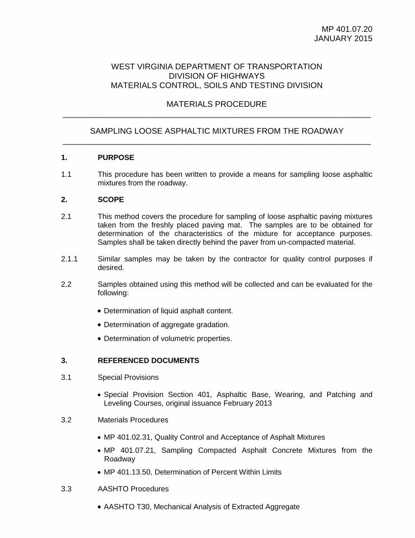
5.2 Acceptance of the asphaltic mixture from the roadway shall be on the basis of test results from loose samples for each Lot. One random sample shall be taken from each Sublot. Samples are to be selected by means of a random sampling plan.

MP 401.07.20 JANUARY 2015 PAGE 3 OF 11
____________________________________________________________________
5.2.1 Random numbers used shall be generated from a calculator or from the Random Number Table attached to this MP. All random numbers shall be recorded and maintained in order to verify the means of sample locations.
5.3 All lots shall be calculated and laid out based on converting 2500 tons to square yardage using the project plan lift thickness and a project theoretical yield. The theoretical yield shall be based on 94% of the design maximum theoretical density from the approved JMF (Form T-400) for asphaltic mixture designs. The lots shall be laid out using the full width of placement for each pull. Partial lots shall be laid out and either considered separate lots or combined with the previous lots as per Table 401.7.1 in the Special Provision for 401.
NOTE: If a lot is laid out that does not end prior to the end of the project, it should wrap around to the next paved lane. If the widths of the two pulls differ, then it will be necessary to calculate the area on the side of the median where the lot is started, then use the remaining area for the lot to determine the length of the remaining portion of the lot on the other pull.
5.3.1 The testable width shall exclude the shoulder adjacent to the median (if included in a single pull) and/or the first foot of any edge of a paving width.
5.3.2 Sample locations determined using random numbers should be rounded to the
nearest foot for both length and offset
5.3.3 Samples determined to fall at the same location as a sample removed from an underlying paving lift should be recalculated using a new random number for either width or length.
5.3.4 Refer to the Illustrative Example included in this MP for examples of how to select samples using a random sampling plan for pavement courses. Loose mix acceptance samples should be cross referenced to the corresponding mat density and bond strength samples as per MP 401.07.21.
5.3.5 For purposes of identification, the sampling ID shall be consistent for projects. Along with the pertinent project identification data (as indicated in Section 401.7.1 of the Special Provision) that is needed for processing test results, it will be necessary to discern all samples on the project by lot, sublot, and type of sample. Samples obtained should be labeled according to the following convention shown below.
Layer/Lot Designation
Lot # Sub Lot # Type of Sample Example Sample ID
B – Base I – Intermediate
S – Surface/Wearing J – Joint Density Core
2 5
M – Mat B – Bond Core
D – Density Core
B2-5M
J2-5

MP 401.07.20 JANUARY 2015 PAGE 4 OF 11
____________________________________________________________________
6. GENERAL SAMPLING PROCEDURE
6.1 Either by Contractor’s personnel in the presence of Division Personnel, or by Division Personnel, loose asphaltic mixture samples shall be lifted at pre-determined random locations, directly from the un-compacted mixture placed by the paving equipment. Samples should be collected using one of the following methods:
6.1.1 Scoop Method: Using a flat bottom, high-sided scoop, the scoop shall pass completely through the entire depth of the lift of material being sampled. When transferring the mixture into a clean cardboard sample box, any fines sticking to the INSIDE of the scoop shall be scraped and included with the sample.
6.1.2 Plate Method: Using a single plate, placed in front of the paver, using cables
remove the sample from the uncompacted mat. Adjacent to the paving operation, remove the outer edges of the material to remove possibly disturbed mix, quarter the material on the plate and retain opposite quarters of the sample. The contractor may retain the remainder of the sample for mirror testing. Divide any remaining fines from the tools and plates between samples.
6.2 After removing the sample material from the un-compacted mat and prior to compactive effort being performed by the rolling operation, each sample location should be immediately backfilled with loose material from the paver.
6.3 In a timely manner the Division should deliver samples to the appropriate Laboratory in which they will be tested.

MP 401.07.20 JANUARY 2015 PAGE 5 OF 11
____________________________________________________________________
Illustrative Example – Project and Lot Layout An exactly four mile long project is to commence paving within the next couple of weeks along an interstate roadway. The division has contacted the contractor to determine the paving sequence and has confirmed that the approved JMF maximum theoretical density is 2501 kg/m3. For theoretical yield on the project, 94% of 2501 kg/m3 is 2351 kg/m3. Dividing by 1000 and then multiplying by 62.4 pcf, the corresponding density in English units is 146.7 pcf. Table 1 - Conversion of Design Bulk Density to Theoretical Application Rate
Project Design Thickness (inches) Conversion for Application Rate (psy) 1.00 0.750 1.25 0.938 1.50 1.125 1.75 1.313 2.00 1.500 2.25 1.688 2.50 1.875 2.75 2.063 3.00 2.250
Using the value for bulk density value, and selecting the proper conversion factor from Table 1 above, the corresponding theoretical application rate per square yard at 1.5 inches thick is determined as follows:
• (Use English units) 146.7 pcf x 1.125 cf/SY = 165 psy (nearest pound) The corresponding lot area for placement of the material in square yards is then calculated as follows:
• (2500 tons x 2000 pounds per ton)/165 psy = 30,303 sy (nearest sy)
Work will begin on the inside fast lane next to the median. The first pull will be 16’ wide. The length of the lot, length per sublot and total area per sublot is calculated as follows:
• 30,303 SY x 9 = 272,727 sf • 272,727 sf/16 = 17,045’ Total lot length (nearest linear foot)
• 17,045/5 = 3409’ length per sublot
• 30,303/5 = 6,061 sy per sublot (nearest sy)
These values will be used to lay out the station for the beginning of each sublot, and also to keep track of the breakdown of a sublot that begins on one side of median and then continues on the other side in an opposite direction. The area for each sublot is used when the situation above occurs and there is a change within the sublot to a pull of a different width.
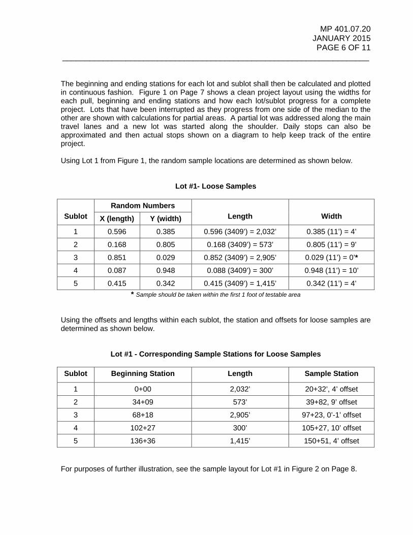
MP 401.07.20 JANUARY 2015 PAGE 6 OF 11
____________________________________________________________________
The beginning and ending stations for each lot and sublot shall then be calculated and plotted in continuous fashion. Figure 1 on Page 7 shows a clean project layout using the widths for each pull, beginning and ending stations and how each lot/sublot progress for a complete project. Lots that have been interrupted as they progress from one side of the median to the other are shown with calculations for partial areas. A partial lot was addressed along the main travel lanes and a new lot was started along the shoulder. Daily stops can also be approximated and then actual stops shown on a diagram to help keep track of the entire project. Using Lot 1 from Figure 1, the random sample locations are determined as shown below.
Lot #1- Loose Samples
Sublot
Random Numbers Length
Width X (length) Y (width)
1 0.596 0.385 0.596 (3409’) = 2,032’ 0.385 (11’) = 4’
2 0.168 0.805 0.168 (3409’) = 573’ 0.805 (11’) = 9’
3 0.851 0.029 0.852 (3409’) = 2,905’ 0.029 (11’) = 0’* 4 0.087 0.948 0.088 (3409’) = 300’ 0.948 (11’) = 10’
5 0.415 0.342 0.415 (3409’) = 1,415’ 0.342 (11’) = 4’ * Sample should be taken within the first 1 foot of testable area
Using the offsets and lengths within each sublot, the station and offsets for loose samples are determined as shown below.
Lot #1 - Corresponding Sample Stations for Loose Samples
Sublot Beginning Station Length Sample Station
1 0+00 2,032’ 20+32’, 4’ offset
2 34+09 573’ 39+82, 9’ offset
3 68+18 2,905’ 97+23, 0’-1’ offset
4 102+27 300’ 105+27, 10’ offset
5 136+36 1,415’ 150+51, 4’ offset
For purposes of further illustration, see the sample layout for Lot #1 in Figure 2 on Page 8.

MP 401.07.20 JANUARY 2015 PAGE 7 OF 11
____________________________________________________________________
Figure 1
Lot 5/ Sublot 5 Lot 2 / Sublot 3
End Mainline Paving
Start Mainline Paving
Start Shoulder Paving
End Shoulder Paving
149+65
95+10
40+55
Lot 6/ Sublot 2500 Ton
Lot 6/ Sublot 3372 Ton
Paved Day 8
54+55
109+10
Begin Project
140 + 00Lot 2 / Sublot 4 136+36
500 Ton
Lot 6/ Sublot 1 Paved Day 1
Lot 4 / Sublot 3 500 Ton
163+65
204+20
Lot 5/ Sublot 1500 Ton
Paved Day 6
Lot 5/ Sublot 2500 Ton
359 Ton Day 6141 Ton Day 7
Lot 5/ Sublot 3500 Ton
Paved Day 7
500 TonPaved Day 7
500 Ton Paved Day 2 200 + 00 Lot 4 / Sublot 218 Ton Day 4 Lot 2 / Sublot 1
183+76 180 + 00
220 + 00
211+20 - EOP 211+20 211+20 211+20 210 + 00
Lot 2 / Sublot 2 204+54 209+50
500 Ton Lot 5/ Sublot 4482 Ton Day 5 500 Ton Paved Day 4
190 + 00 Paved Day 2
Lot 1 / Sublot 5Lot 4 / Sublot 4 160 + 00 500 Ton
500 Ton 100 Ton Day 1 Lot 4 / Sublot 1
500 Ton 500 Ton 170+45Paved Day 7 Paved Day 2 170 + 00
167+45 164+05
Paved Day 5 400 Ton Day 2 500 Ton
150 + 00 Paved Day 4149+67
120 + 00 118+60Paved Day 7
50 Ton Day 2 130 + 00 Lot 1 / Sublot 4450 Ton Day 3 500 Ton
Lot 4 / Sublot 5 115+58500 Ton 110 + 00 Lot 3 / Sublot 5
265 Ton Day 5 Lot 2 / Sublot 5
500 Ton 122+00
500 Ton
90 + 00 Paved Day 1
500 Ton235 Ton Day 6 500 Ton 102+27 Paved Day 4
Paved Day 3 100 + 00Lot 1 / Sublot 3
500 Ton 70 + 00 68+1859 Ton Day 7 Lot 4 / Sublot 6 Paved Day 3 Lot 3 / Sublot 4
81+49 80 + 00
76+55 Lot 3 / Sublot 1 73+15
20 + 00 Paved Day 1
441 Ton Day 8 500 Ton 500 TonPaved Day 6 60 + 00 Lot 1 / Sublot 2 Paved Day 4
500 TonPaved Day 1
0 + 000+00
305 Ton Day 413+31 10 + 00
Project Layout By Area - With Estimated Daily Paving Stops
500 TonPaved Day 6 195 Ton Day 3
31+10 30 + 00 27+70Lot 1 / Sublot 1
Lot 4 / Sublot 7 500 Ton Lot 3 / Sublot 3
50 + 00
47+40Lot 3 / Sublot 2 40 + 00
500 Ton 34+09Paved Day 3
342 Ton
227 sy
Project Median
Proj
ectM
edia
n
Proj
ectM
edia
n4'
Sho
ulde
r
4' S
houl
der
10' S
houl
der
10' S
houl
der
4147 sy3695 sy
5834 sy5283 sy
778 sy 1184 sy
4877 sy
4506 sy
MP 401.07.20 JANUARY 2015 PAGE 8 OF 11
____________________________________________________________________
All locations for loose samples, mat density cores, and bond strength cores are shown in Figure 2 below. Refer to MP 401.07.21 for more information on sampling cores for density and bond strength.
Figure 2 – Lot #1 Sample Layout
Using the same methodology and following the continuous lots in correspondence to paving sequence, the entire project layout for sampling can be completed as shown in Figure 3. After Figure 3, a summary is shown to help quantify the daily and total sampling efforts for the project.

MP 401.07.20 JANUARY 2015 PAGE 9 OF 11
____________________________________________________________________
Figure 3
= Joint Cores= Bond Cores= Compaction Cores= Loose Asphalt Samples
500 Ton 200 + 00
Project Layout with Sampling Plan - Density and Bond Cores, Loose Mix Samples
500 Ton
54+55
109+10
500 Ton
190 + 00
Lot 6/ Sublot 2500 Ton
Lot 6/ Sublot 1500 Ton
Lot 5/ Sublot 3500 Ton
211+20
209+50 500 Ton
164+05Lot 1 / Sublot 5
160 + 00
500 Ton
204+20
Lot 5/ Sublot 5
149+65
95+10
40+55
163+65
220 + 00
211+20 - EOP 211+20 211+20 210 + 00
Lot 4 / Sublot 3 Lot 2 / Sublot 2 204+54
Lot 5/ Sublot 4
Lot 4 / Sublot 4500 Ton 500 Ton
500 Ton 170+45 170 + 00
167+45
183+76
500 Ton Lot 4 / Sublot 1
Lot 2 / Sublot 1 Lot 4 / Sublot 2500 Ton
500 Ton 102+27
100 + 00
150 + 00149+67
140 + 00Lot 2 / Sublot 4 136+36
500 Ton
Lot 2 / Sublot 5 500 Ton
130 + 00 Lot 1 / Sublot 4500 Ton
180 + 00Lot 2 / Sublot 3
122+00 120 + 00 118+60
Lot 3 / Sublot 1 73+15
Lot 1 / Sublot 3
90 + 00 500 Ton
Lot 4 / Sublot 5 115+58500 Ton 110 + 00 Lot 3 / Sublot 5
Lot 5/ Sublot 2500 Ton
Lot 4 / Sublot 6 500 Ton 70 + 00 68+18Lot 3 / Sublot 4
81+49 80 + 00
76+55
500 Ton500 Ton
47+40Lot 3 / Sublot 2 40 + 00
500 Ton 34+09
500 Ton
60 + 00 Lot 1 / Sublot 2
Lot 5/ Sublot 1500 Ton
20 + 00 Lot 3 / Sublot 3
50 + 00
Start Mainline Paving
Lot 6/ Sublot 3372 Ton
Begin Project
13+31 10 + 00
0 + 000+00End Mainline
PavingEnd Shoulder
Paving
500 Ton
31+10 30 + 00 27+70Lot 1 / Sublot 1
Lot 4 / Sublot 7 500 Ton
342 Ton
Start Shoulder Paving
Proj
ectM
edia
n
Proj
ectM
edia
n
4' S
houl
der
4' S
houl
der
10' S
houl
der
10' S
houl
der
Joint Lot 1
Joint Lot 2
Joint Lot 3
Joint Lot 5
Joint Lot 6
Joint Lot 4
Joint Lot 7
Joint Lot 8
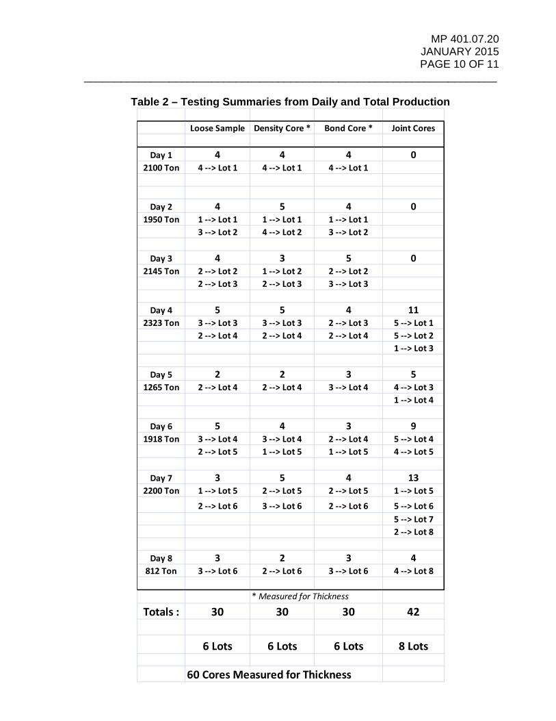
MP 401.07.20 JANUARY 2015 PAGE 10 OF 11
____________________________________________________________________
Table 2 – Testing Summaries from Daily and Total Production
Loose Sample Density Core * Bond Core * Joint Cores
Day 1 4 4 4 02100 Ton 4 --> Lot 1 4 --> Lot 1 4 --> Lot 1
Day 2 4 5 4 01950 Ton 1 --> Lot 1 1 --> Lot 1 1 --> Lot 1
3 --> Lot 2 4 --> Lot 2 3 --> Lot 2
Day 3 4 3 5 02145 Ton 2 --> Lot 2 1 --> Lot 2 2 --> Lot 2
2 --> Lot 3 2 --> Lot 3 3 --> Lot 3
Day 4 5 5 4 112323 Ton 3 --> Lot 3 3 --> Lot 3 2 --> Lot 3 5 --> Lot 1
2 --> Lot 4 2 --> Lot 4 2 --> Lot 4 5 --> Lot 21 --> Lot 3
Day 5 2 2 3 51265 Ton 2 --> Lot 4 2 --> Lot 4 3 --> Lot 4 4 --> Lot 3
1 --> Lot 4
Day 6 5 4 3 91918 Ton 3 --> Lot 4 3 --> Lot 4 2 --> Lot 4 5 --> Lot 4
2 --> Lot 5 1 --> Lot 5 1 --> Lot 5 4 --> Lot 5
Day 7 3 5 4 132200 Ton 1 --> Lot 5 2 --> Lot 5 2 --> Lot 5 1 --> Lot 5
2 --> Lot 6 3 --> Lot 6 2 --> Lot 6 5 --> Lot 65 --> Lot 72 --> Lot 8
Day 8 3 2 3 4812 Ton 3 --> Lot 6 2 --> Lot 6 3 --> Lot 6 4 --> Lot 8
* Measured for Thickness
Totals : 30 30 30 42
6 Lots 6 Lots 6 Lots 8 Lots
60 Cores Measured for Thickness

MP 401.07.20 JANUARY 2015 PAGE 11 OF 11
____________________________________________________________________
Table 3 - Random Numbers
.858 .082 .886 .125 .263 .176 .551 .711 .355 .698
.576 .417 .242 .316 .960 .819 .444 .323 .331 .179
.687 .288 .835 .636 .596 .174 .866 .685 .066 .170
.068 .391 .739 .002 .159 .423 .629 .631 .979 .399
.140 .324 .215 .358 .663 .193 .215 .667 .627 .595
.574 .601 .623 .855 .339 .486 .065 .627 .458 .137
.966 .529 .757 .308 .025 .836 .200 .055 .510 .656
.608 .910 .944 .281 .539 .371 .217 .882 .324 .284
.215 .355 .645 .460 .719 .057 .237 .146 .135 .903
.761 .883 .771 .388 .928 .654 .815 .570 .539 .600
.869 .222 .115 .447 .658 .989 .921 .924 .560 .447
.562 .036 .302 .673 .911 .512 .972 .576 .838 .014
.481 .791 .454 .731 .770 .500 .980 .183 .385 .012
.599 .966 .356 .183 .797 .503 .180 .657 .077 .165
.464 .747 .299 .530 .675 .646 .385 .109 .780 .699
.675 .654 .221 .777 .172 .738 .324 .669 .079 .587
.279 .707 .372 .486 .340 .680 .928 .397 .337 .564
.338 .917 .942 .985 .838 .805 .278 .898 .906 .939
.316 .935 .403 .629 .130 .575 .195 .887 .142 .488
.011 .283 .762 .988 .102 .068 .902 .850 .569 .977
.683 .441 .572 .486 .732 .721 .275 .023 .088 .402
.493 .155 .530 .125 .841 .171 .794 .850 .797 .367
.059 .502 .963 .055 .128 .655 .043 .293 .792 .739
.996 .729 .370 .139 .306 .858 .183 .464 .457 .863
.240 .972 .495 .696 .350 .642 .188 .135 .470 .765

MP 401.07.21 JANUARY 2015
WEST VIRGINIA DEPARTMENT OF TRANSPORTATION DIVISION OF HIGHWAYS
MATERIALS CONTROL, SOILS AND TESTING DIVISION
MATERIALS PROCEDURE ____________________________________________________________________
SAMPLING COMPACTED ASPHALTIC MIXTURES FROM THE ROADWAY ____________________________________________________________________
1. PURPOSE
1.1 This procedure has been written to provide a means for sampling compacted roadway asphaltic mixtures.
2. SCOPE
2.1 This method covers the procedure for sampling of asphaltic paving mixtures taken from the finished pavement for determination of the characteristics of the compacted mixture. Alternative methods of sampling may be found in AASHTO T-230.
2.2 Samples obtained using this method will be collected for several reasons including but not limited to the following:
2.2.1 Visual examination.
2.2.2 Measurement for layer thickness.
2.2.3 Determination of bulk specific gravity, air voids, and other volumetric properties.
2.2.4 Determination of bond strength between constructed layers.
3. REFERENCED DOCUMENTS
3.1 Special Provisions
• Special Provision Section 401, Asphaltic Base, Wearing, and Patching and Leveling Courses, original issuance February 2013
3.2 Materials Procedures
• MP 401.02.31, Quality Control and Acceptance of Asphalt Mixtures
• MP 401.07.20, Sampling Loose Asphaltic Mixtures
• MP 401.07.22, Measurement for Thickness of Asphalt Pavement Using Drilled Cores
• MP 401.07.23, Interface Bond Shear Strength of Multi-layered Asphalt Pavement Specimens
• MP 401.13.50, Determination of Percent Within Limits

MP 401.07.21 JANUARY 2015 PAGE 2 OF 13
____________________________________________________________________
3.3 AASHTO Procedures
• AASHTO T-331, Bulk Specific Gravity and Density of Compacted Hot Mix Asphalt (HMA) Using Automatic Vacuum Sealing Method
4. EQUIPMENT AND TOOLS
4.1 Powered core drill, water cooled, equipped to core cylindrical samples.
4.2 Diamond drill bit of six (6) inch inside diameter size.
4.3 Incidental materials and equipment.
4.4 Hand-held core sample extraction tool capable of grasping and removing a drilled cylindrical pavement core sample from the pavement without damage to the core sample.
Note: Worn drill bits of the same size as those used for coring have been successfully used by cutting slots vertically along the side of the casing to allow for expansion.
4.5 An ice cooler large enough to hold the sample without distortion after it is removed from the pavement.
Note: Large ice coolers (approximately 150 quart) have been used successfully to store and transport multiple pavement cores.
4.6 Small plastic bags for core specimens
4.7 Masking tape
4.8 A marking pencil, lumber crayon or other means suitable for labeling cores.
4.9 Markers for labeling the plastic bags.
5. MAT DENSITY, BOND STRENGTH, AND THICKNESS CORE SAMPLES
5.1 Density acceptance of the asphaltic mixture from the roadway shall be determined on the basis of test results from core samples for each Lot. One sample shall be taken from each Sublot. Samples are to be selected by means of a random sampling plan.
5.1.1 Random numbers used shall be generated from a calculator or from the Random Number Table attached to this MP. All random numbers shall be recorded and maintained in order to verify the means of sample locations.
5.2 At the Pre-Paving Meeting, WVDOH and Contractor personnel shall confer and agree on the sequence and widths of the paving operation in order for a sampling plan to be developed by the Division. The plan shall begin at the intended starting

MP 401.07.21 JANUARY 2015 PAGE 3 OF 13
____________________________________________________________________
point and progress continuously until the end of the paving operation. Lots for mainline travel lanes should not be extended onto outside shoulders. As paving progresses onto the outside shoulders, new lots shall be established along the shoulders.
5.3 All lots shall be calculated and laid out based on converting 2500 tons to square yardage using the project plan lift thickness and a project theoretical yield. The theoretical yield shall be based on 94% of the design maximum theoretical density from the approved JMF (Form T-400) for asphaltic mixture designs. The lots shall be laid out using the full width of placement for each pull. However, no samples shall be taken from the inside shoulder adjacent to the median (generally four feet in width), or the outside 12 inches (one foot) of the unsupported or supported edge of a paving mat. The remaining dimension of width shall be considered testable and used to determine the random location of each sample. Partial lots shall be laid out and either considered separate lots or combined with the previous lots as per Table 401.7.1 in the Special Provision for 401.
5.3.1 Sample locations determined using random numbers shall be rounded to the nearest 1ft for both length and offset. If it is determined that the offset is zero or the maximum dimension in the testable width, the samples should be taken within either the first or last one foot respectively of material at each side of the testable width. Additionally, samples determined to fall at the same location as a sample removed from an underlying paving lift should be recalculated using a new random number for either width or length.
NOTE: It is likely that some lots will be laid out in the field beginning with a mat that is a different dimension than that where the lot ends. Such would be the case for a lot that starts within a mat being pulled along the median where the fast lane and inside shoulder are being pulled simultaneously (approximately 16’), but ends along the outside or slow lane (approximately 12’) on the other side of the median. In such a case, it will be necessary to calculate the area on the side of the median where the lot is started, then use the remaining area for the lot to determine the length of the remaining portion of the lot on the other side of the median.
5.4 Refer to the Illustrative Example included in this MP for examples of how to select samples using a random sampling plan for pavement courses. Density acceptance samples and bond strength samples should be cross referenced to a corresponding mixture acceptance sample as per MP 401.07.20.
5.4.1 For purposes of identification, the sampling ID shall be consistent for projects. Along with the pertinent project identification data (as indicated in Section 401.7.1 of the Special Provision) that is needed for processing test results, it will be necessary to discern all samples on the project by lot, sublot, and type of sample. For mat density and bond strength samples obtained from the mat, and for joint density samples obtained from the longitudinal joint, they should follow the convention shown below. Please note that mat density and bond strength samples will be also measured for thickness.

MP 401.07.21 JANUARY 2015 PAGE 4 OF 13
____________________________________________________________________
Layer/Lot Designation
Lot # Sub Lot # Type of Sample Example Sample ID
B – Base I – Intermediate
S – Surface/Wearing J – Joint Density Core
2 5
M – Mat B – Bond Core
D – Density Core
B2-5M
J2-5 5.5 Samples for mat density shall be used to determine the percent compaction of the
finished mat by first determining the bulk specific gravity of each specimen as per AASHTO T-331, and then by dividing by the corresponding daily theoretical maximum density of the paving mixture.
6. LONGITUDINAL JOINT DENSITY CORE SAMPLES
6.1 Samples shall be taken on the basis of a random sampling plan established for each lot. Lots shall be established as specified in Special Provision 401, Section 401.7 - Acceptance Testing and will consist of 10,000’ of constructed longitudinal joint. Each lot will be further divided into sublots consisting of 2,000’. Partial lots shall be addressed as described within Section 401.7.1.2 of the Special Provision. Lots along constructed joints between travel lanes shall not extend onto the constructed joint adjacent to the outside shoulders. New lots shall begin with the constructed adjacent to the outside shoulders.
6.2 One sample shall be taken from each sublot. Refer to Illustrative Example No. 3 in the Appendix of this MP for an example of how to select samples using a random sampling plan.
6.3 A core sample taken from a longitudinal vertical joint shall be centered on the line where the joint between the two adjacent lifts abut at the surface as illustrated in Figure 1 below. The center of all vertical joint cores shall be within one (1) inch of this joint line.
6.4 When the two lanes forming the longitudinal joint have daily theoretical maximum specific gravity values differing by more than 0.050, particular attention should be paid to these core locations. Examine each longitudinal joint core sample to ensure that approximately one-half of the longitudinal joint core sample is from each lane. If the materials in the longitudinal joint core are unbalanced, take a replacement sample at a location within twelve (12) inches longitudinally of the original sample location and adjust the location of the core drill relative to the joint line to ensure approximately equal material on each side of the joint will be obtained in the core sample.

MP 401.07.21 JANUARY 2015 PAGE 5 OF 13
____________________________________________________________________
Figure 1 – Cross-sectional View, Position of Core Along Longitudinal Joint
6.5 Samples for joint density shall be used to determine the percent compaction of the
finished mat by first determining the bulk specific gravity of each specimen as per AASHTO T-331, and then by dividing by the corresponding daily theoretical maximum density of the paving mixture.
7. GENERAL CORING AND SAMPLING PROCEDURE
7.1 In the presence of the Engineer’s representative, the contractor shall core and identify the density acceptance samples as specified in Special Provision 401.
7.2 Efforts should be taken to cool the pavement with ice or other suitable means prior to coring. Using the powered core drill, drill core samples to the specified diameter and to a depth sufficiently below the depth of the pavement course to be sampled. Ensure sufficient water is dispersed through the core bit during drilling to keep the drill bit and core sample cool enough in order to allow cutting through the pavement without damaging the sample and the core bit. Carefully and slowly lower the drill bit to the surface of the pavement course at the start of drilling to prevent the drill bit from moving and to obtain a smooth clean initial drill cut at the surface of the core sample. After drilling to a sufficient depth, carefully raise the core drill bit to prevent any damage to the core sample.
7.2.1 Additional care should be taken when laying out and drilling samples for bond strength testing. Prior to drilling the sample, mark the pavement within the area to be cored using a lumber crayon or other suitable means in order to indicate the direction of traffic. Also, efforts need to be taken to ensure that the core drill bit is plumb so that a sample is not skewed after removal. Skewed samples will likely not be suitable for testing in the shear testing apparatus.
7.3 Carefully dislodge or break the core sample away from the underlying pavement layer. Do not distort, bend, crack, damage or physically change the physical condition of the core sample during this operation.

MP 401.07.21 JANUARY 2015 PAGE 6 OF 13
____________________________________________________________________
7.4 Using a hand-held core sample extraction tool, carefully grasp and remove the core sample from the pavement. Do not distort, bend, crack, damage or physically change the physical condition of the core sample during removal from the pavement.
7.5 Immediately after removing the core sample from the pavement, wash off the core sample with water to remove the fine material generated from the drilling operation. Air dry or towel dry the core sample sufficiently to allow identification of the Lot and sublot number on each core sample by using a paint pen, or other suitable means.
7.6 If a core sample includes materials other than the material or pavement course to be tested, clearly show and mark with a paint pen the section(s) of each core sample to be discarded. Core samples suspected of including more than one material and not clearly showing the section to test, and the section(s) to discard, will be considered non-conforming samples and will not be tested until the section to test is identified.
7.7 Once the core sample has been obtained and identified, the Division will take immediate possession of the core sample and store it in a proper environment. Overheating or impact can damage core samples and prevent accurate test results.
7.8 Samples should be placed in separate small plastic bags and stored out of direct sunlight and/or placed in a cooler with enough ice to prevent them from warming up. The sample bags can be marked ahead of time to further help identify individual samples once transported to the lab. Core samples should then be laid in the cooler with the top surface (flat) down on the bottom of the cooler to prevent movement.
7.9 During the same work shift for placement of the sampled asphalt concrete mix, each core hole location should be backfilled with compacted mixture of the same material being used for paving, or other preapproved method. Efforts should be taken to clean the hole of loose debris and any standing water should be removed.
7.10 After the Lot is completed or has been terminated, or at the end of each days placement, the Division personnel will transport the core samples from each day’s production to the District Materials Laboratory or Materials Control, Soils & Testing Division for additional processing and evaluation.

MP 401.07.21 JANUARY 2015 PAGE 7 OF 13
____________________________________________________________________
Illustrative Example – Project and Lot Layout An exactly four mile long project is to commence paving within the next couple of weeks along an interstate roadway. The division has contacted the contractor to determine the paving sequence and widths, and has confirmed that the approved JMF maximum theoretical density is 2501 kg/m3. For theoretical yield on the project, 94% of 2501 kg/m3 is 2351 kg/m3. Dividing by 1000 and then multiplying by 62.4 pcf, the corresponding density in English units is 146.7 pcf. Using this value, and selecting the proper conversion factor from Table 1 below, the corresponding application rate per square yard at 1.5 inches thick is determined as follows: Table 1 - Conversion of Design Bulk Density to In-Situ Application Rate
Project Design Thickness (inches) Conversion for Application Rate (psy) 1.00 0.750 1.25 0.938 1.50 1.125 1.75 1.313 2.00 1.500 2.25 1.688 2.50 1.875 2.75 2.063 3.00 2.250
• (Use English units) 146.7 pcf x 1.125 cf/SY = 165 psy (nearest pound)
The corresponding lot area for placement of the material in square yards is then calculated as follows:
• (2500 tons x 2000 pounds per ton)/165 psy = 30,303 sy (nearest sy)
Work will begin on the inside fast lane next to the median. The first pull will be 16’ wide. The length of the lot, length per sublot and total area per sublot is calculated as follows:
• 30,303 SY x 9 = 272,727 sf
• 272,727 sf/16 = 17,045’ Total lot length (nearest linear foot)
• 17,045/5 = 3409’ length per sublot
• 30,303/5 = 6,061 sy per sublot (nearest sy)
These values will be used to lay out the station for the beginning of each sublot, and also to keep track of the breakdown of a sublot that begins on one side of median and then continues on the other side in an opposite direction. The area for each sublot is used when the situation above occurs and there is a change within the sublot to a pull of a different width. The beginning and ending stations for each lot and sublot shall then be calculated and plotted in continuous fashion. Figure 2 shows a clean project layout using the widths for each pull, beginning and ending stations and how each lot/sublot progress for a complete project. Daily stops can also be approximated and then actual stops shown on a diagram to help keep track of the entire project. Partial mat and joint lots were addressed along the main travel lanes and new lots were started along the shoulder.

MP 401.07.21 JANUARY 2015 PAGE 8 OF 13
____________________________________________________________________
Figure 2
Lot 5/ Sublot 5 Lot 2 / Sublot 3
End Mainline Paving
Start Mainline Paving
Start Shoulder Paving
End Shoulder Paving
149+65
95+10
40+55
Lot 6/ Sublot 2500 Ton
Lot 6/ Sublot 3372 Ton
Paved Day 8
54+55
109+10
Begin Project
140 + 00Lot 2 / Sublot 4 136+36
500 Ton
Lot 6/ Sublot 1 Paved Day 1
Lot 4 / Sublot 3 500 Ton
163+65
204+20
Lot 5/ Sublot 1500 Ton
Paved Day 6
Lot 5/ Sublot 2500 Ton
359 Ton Day 6141 Ton Day 7
Lot 5/ Sublot 3500 Ton
Paved Day 7
500 TonPaved Day 7
500 Ton Paved Day 2 200 + 00 Lot 4 / Sublot 218 Ton Day 4 Lot 2 / Sublot 1
183+76 180 + 00
220 + 00
211+20 - EOP 211+20 211+20 211+20 210 + 00
Lot 2 / Sublot 2 204+54 209+50
500 Ton Lot 5/ Sublot 4482 Ton Day 5 500 Ton Paved Day 4
190 + 00 Paved Day 2
Lot 1 / Sublot 5Lot 4 / Sublot 4 160 + 00 500 Ton
500 Ton 100 Ton Day 1 Lot 4 / Sublot 1
500 Ton 500 Ton 170+45Paved Day 7 Paved Day 2 170 + 00
167+45 164+05
Paved Day 5 400 Ton Day 2 500 Ton
150 + 00 Paved Day 4149+67
120 + 00 118+60Paved Day 7
50 Ton Day 2 130 + 00 Lot 1 / Sublot 4450 Ton Day 3 500 Ton
Lot 4 / Sublot 5 115+58500 Ton 110 + 00 Lot 3 / Sublot 5
265 Ton Day 5 Lot 2 / Sublot 5
500 Ton 122+00
500 Ton
90 + 00 Paved Day 1
500 Ton235 Ton Day 6 500 Ton 102+27 Paved Day 4
Paved Day 3 100 + 00Lot 1 / Sublot 3
500 Ton 70 + 00 68+1859 Ton Day 7 Lot 4 / Sublot 6 Paved Day 3 Lot 3 / Sublot 4
81+49 80 + 00
76+55 Lot 3 / Sublot 1 73+15
20 + 00 Paved Day 1
441 Ton Day 8 500 Ton 500 TonPaved Day 6 60 + 00 Lot 1 / Sublot 2 Paved Day 4
500 TonPaved Day 1
0 + 000+00
305 Ton Day 413+31 10 + 00
Project Layout By Area - With Estimated Daily Paving Stops
500 TonPaved Day 6 195 Ton Day 3
31+10 30 + 00 27+70Lot 1 / Sublot 1
Lot 4 / Sublot 7 500 Ton Lot 3 / Sublot 3
50 + 00
47+40Lot 3 / Sublot 2 40 + 00
500 Ton 34+09Paved Day 3
342 Ton
227 sy
Project MedianPr
ojec
tMed
ian
Proj
ectM
edia
n4'
Sho
ulde
r
4' S
houl
der
10' S
houl
der
10' S
houl
der
4147 sy3695 sy
5834 sy5283 sy
778 sy 1184 sy
4877 sy
4506 sy

MP 401.07.21 JANUARY 2015 PAGE 9 OF 13
____________________________________________________________________
Using Lot 1 from Figure 2, the random sample locations are determined as shown below:
Lot #1-Density Cores
Sublot
Random Numbers Length
Width X (length) Y (width)
1 0.632 0.287 0.632 (3409’) = 2,155’ 0.287 (11’) = 3’
2 0.534 0.264 0.534 (3409’) = 1,820’ 0.264 (11’) = 3’
3 0.871 0.159 0.871 (3409’) = 2,969’ 0.159 (11’) = 2’
4 0.753 0.177 0.753 (3409’) = 2,567’ 0.177 (11’) = 2’
5 0.277 0.530 0.277 (3409’) = 944’ 0.530 (11’) = 6’
Lot #1- Bond Strength Cores
Sublot Random Numbers
Length
Width X (length) Y (width)
1 0.149 0.155 0.149 (3409’) = 508’ 0.155 (11’) = 2’
2 0.239 0.992 0.239 (3409’) = 815’ 0.992 (11’) = 11’*
3 0.295 0.480 0.295 (3409’) = 1,006’ 0.480 (11’) = 5’
4 0.517 0.473 0.517 (3409’) = 1,762’ 0.473 (11’) = 5’
5 0.805 0.741 0.805 (3409’) = 2,744 0.741 (11’) = 8’ * Sample should be taken between 10’-11’ offset
Using the offsets and lengths within each sublot, the stations and offsets for Mat Density and Bond Strength Core samples are determined as shown below.
Lot #1 - Corresponding Sample Stations for Mat Density –
Sublot Beginning Station Length Sample Station
1 0+00 2,155 21+55, 3’ offset
2 34+09 1,820’ 52+29’, 3 offset
3 68+18 2,969’ 97+87, 2’ offset
4 102+27 2,567’ 127+94, 2’ offset
5 136+36 944’ 145+80, 6’ offset

MP 401.07.21 JANUARY 2015 PAGE 10 OF 13
____________________________________________________________________
Lot #1 - Corresponding Sample Stations for Bond Strength
Sublot Beginning Station Length Sample Station
1 0+00 508’ 5+08, 2’ offset
2 34+09 815’ 42+24, 10’ offset
3 68+18 1,006’ 78+24, 5’ offset
4 102+27 1,762’ 119+89, 5’ offset
5 136+36 2,744’ 163+80, 8’ offset
For purposes of illustration, all locations for loose samples, mat density cores, and bond strength cores are shown in Figure 3 below. Refer to MP 401.07.20 for more information on obtaining loose samples of asphaltic mixture for determination of asphalt content and gradation.
Figure 3
Using the same methodology and following the continuous lots in correspondence to paving sequence, the entire project layout for sampling can be completed as shown in Figure 4. Longitudinal joint lots begin at Station 0+00 between the fast and slow lanes and Joint Lot 1 ends at 10+00. Joint Lot 3 begins at Sta. 20+00 and continues to the other side of the median and extends the amount of the lot remaining. After Figure 4, a summary is shown to help quantify the daily and total sampling efforts for the project.
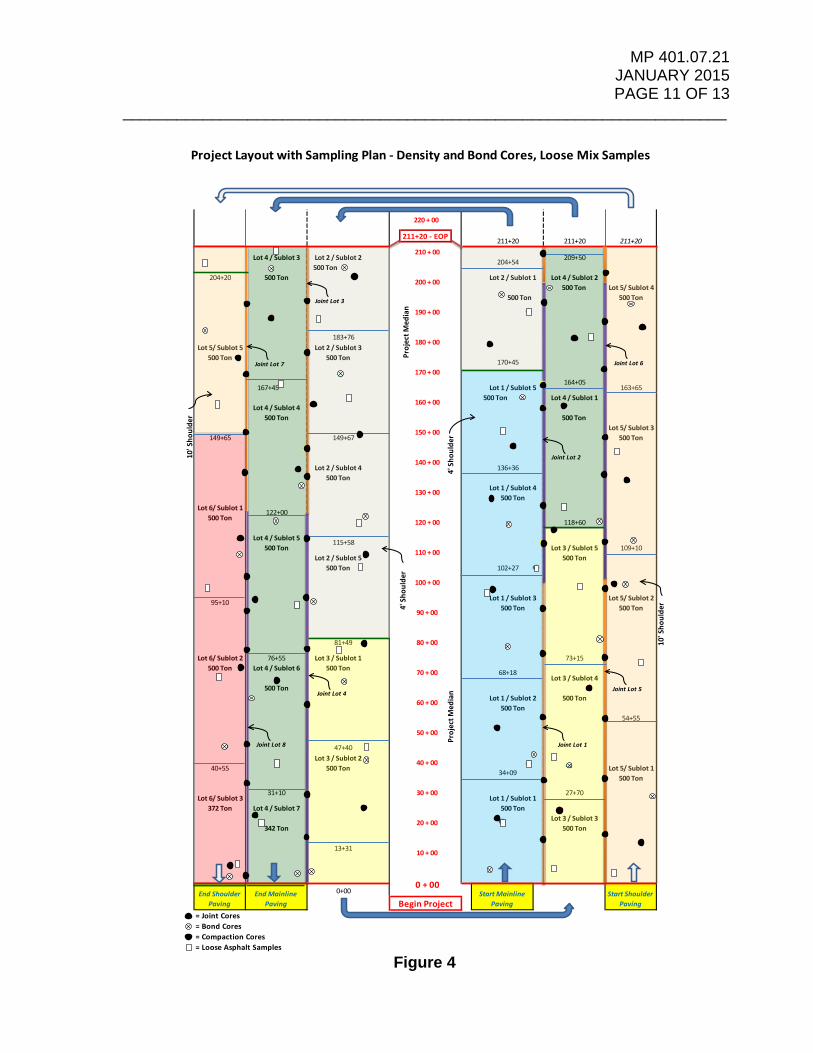
MP 401.07.21 JANUARY 2015 PAGE 11 OF 13
____________________________________________________________________
Figure 4
= Joint Cores= Bond Cores= Compaction Cores= Loose Asphalt Samples
500 Ton 200 + 00
Project Layout with Sampling Plan - Density and Bond Cores, Loose Mix Samples
500 Ton
54+55
109+10
500 Ton
190 + 00
Lot 6/ Sublot 2500 Ton
Lot 6/ Sublot 1500 Ton
Lot 5/ Sublot 3500 Ton
211+20
209+50 500 Ton
164+05Lot 1 / Sublot 5
160 + 00
500 Ton
204+20
Lot 5/ Sublot 5
149+65
95+10
40+55
163+65
220 + 00
211+20 - EOP 211+20 211+20 210 + 00
Lot 4 / Sublot 3 Lot 2 / Sublot 2 204+54
Lot 5/ Sublot 4
Lot 4 / Sublot 4500 Ton 500 Ton
500 Ton 170+45 170 + 00
167+45
183+76
500 Ton Lot 4 / Sublot 1
Lot 2 / Sublot 1 Lot 4 / Sublot 2500 Ton
500 Ton 102+27
100 + 00
150 + 00149+67
140 + 00Lot 2 / Sublot 4 136+36
500 Ton
Lot 2 / Sublot 5 500 Ton
130 + 00 Lot 1 / Sublot 4500 Ton
180 + 00Lot 2 / Sublot 3
122+00 120 + 00 118+60
Lot 3 / Sublot 1 73+15
Lot 1 / Sublot 3
90 + 00 500 Ton
Lot 4 / Sublot 5 115+58500 Ton 110 + 00 Lot 3 / Sublot 5
Lot 5/ Sublot 2500 Ton
Lot 4 / Sublot 6 500 Ton 70 + 00 68+18Lot 3 / Sublot 4
81+49 80 + 00
76+55
500 Ton500 Ton
47+40Lot 3 / Sublot 2 40 + 00
500 Ton 34+09
500 Ton
60 + 00 Lot 1 / Sublot 2
Lot 5/ Sublot 1500 Ton
20 + 00 Lot 3 / Sublot 3
50 + 00
Start Mainline Paving
Lot 6/ Sublot 3372 Ton
Begin Project
13+31 10 + 00
0 + 000+00End Mainline
PavingEnd Shoulder
Paving
500 Ton
31+10 30 + 00 27+70Lot 1 / Sublot 1
Lot 4 / Sublot 7 500 Ton
342 Ton
Start Shoulder Paving
Proj
ectM
edia
n
Proj
ectM
edia
n
4' S
houl
der
4' S
houl
der
10' S
houl
der
10' S
houl
der
Joint Lot 1
Joint Lot 2
Joint Lot 3
Joint Lot 5
Joint Lot 6
Joint Lot 4
Joint Lot 7
Joint Lot 8

MP 401.07.21 JANUARY 2015 PAGE 12 OF 13
____________________________________________________________________
Table 2 – Testing Summaries from Daily and Total Production
Loose Sample Density Core * Bond Core * Joint Cores
Day 1 4 4 4 02100 Ton 4 --> Lot 1 4 --> Lot 1 4 --> Lot 1
Day 2 4 5 4 01950 Ton 1 --> Lot 1 1 --> Lot 1 1 --> Lot 1
3 --> Lot 2 4 --> Lot 2 3 --> Lot 2
Day 3 4 3 5 02145 Ton 2 --> Lot 2 1 --> Lot 2 2 --> Lot 2
2 --> Lot 3 2 --> Lot 3 3 --> Lot 3
Day 4 5 5 4 112323 Ton 3 --> Lot 3 3 --> Lot 3 2 --> Lot 3 5 --> Lot 1
2 --> Lot 4 2 --> Lot 4 2 --> Lot 4 5 --> Lot 21 --> Lot 3
Day 5 2 2 3 51265 Ton 2 --> Lot 4 2 --> Lot 4 3 --> Lot 4 4 --> Lot 3
1 --> Lot 4
Day 6 5 4 3 91918 Ton 3 --> Lot 4 3 --> Lot 4 2 --> Lot 4 5 --> Lot 4
2 --> Lot 5 1 --> Lot 5 1 --> Lot 5 4 --> Lot 5
Day 7 3 5 4 132200 Ton 1 --> Lot 5 2 --> Lot 5 2 --> Lot 5 1 --> Lot 5
2 --> Lot 6 3 --> Lot 6 2 --> Lot 6 5 --> Lot 65 --> Lot 72 --> Lot 8
Day 8 3 2 3 4812 Ton 3 --> Lot 6 2 --> Lot 6 3 --> Lot 6 4 --> Lot 8
* Measured for Thickness
Totals : 30 30 30 42
6 Lots 6 Lots 6 Lots 8 Lots
60 Cores Measured for Thickness
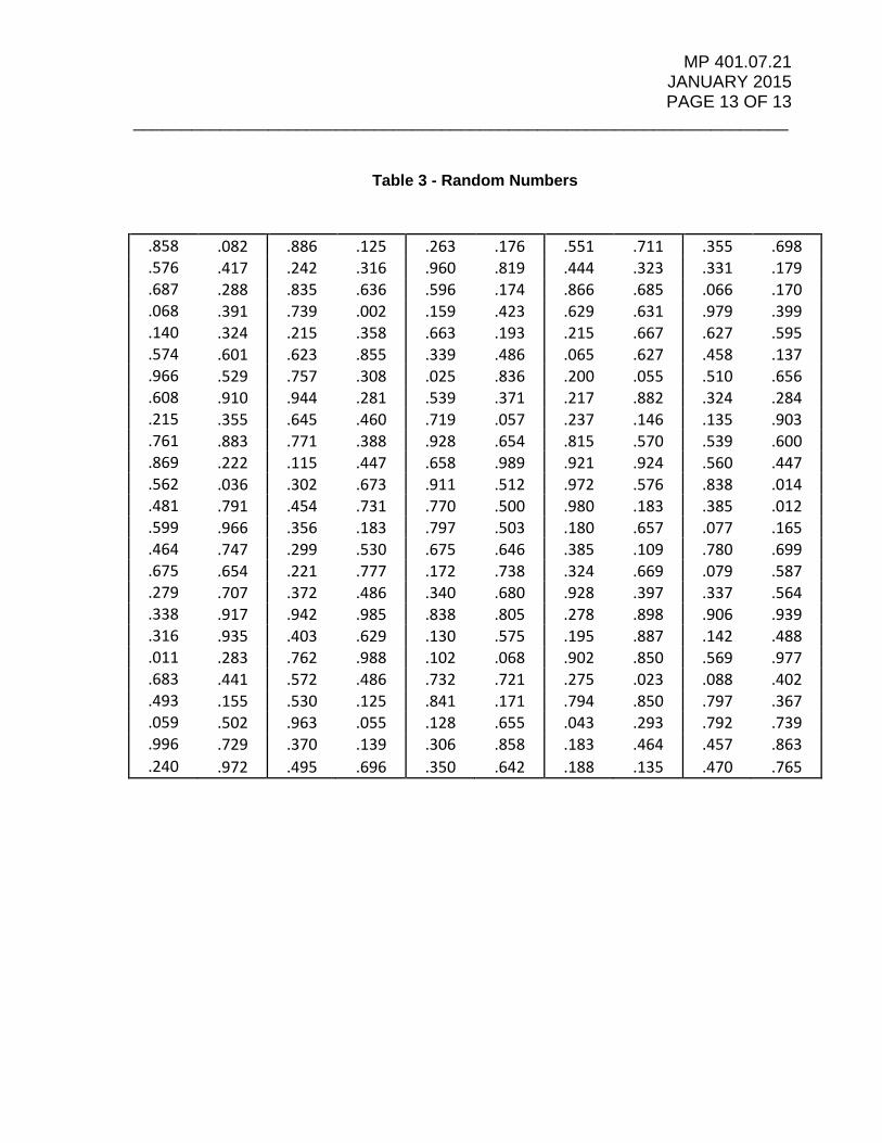
MP 401.07.21 JANUARY 2015 PAGE 13 OF 13
____________________________________________________________________
Table 3 - Random Numbers
.858 .082 .886 .125 .263 .176 .551 .711 .355 .698
.576 .417 .242 .316 .960 .819 .444 .323 .331 .179
.687 .288 .835 .636 .596 .174 .866 .685 .066 .170
.068 .391 .739 .002 .159 .423 .629 .631 .979 .399
.140 .324 .215 .358 .663 .193 .215 .667 .627 .595
.574 .601 .623 .855 .339 .486 .065 .627 .458 .137
.966 .529 .757 .308 .025 .836 .200 .055 .510 .656
.608 .910 .944 .281 .539 .371 .217 .882 .324 .284
.215 .355 .645 .460 .719 .057 .237 .146 .135 .903
.761 .883 .771 .388 .928 .654 .815 .570 .539 .600
.869 .222 .115 .447 .658 .989 .921 .924 .560 .447
.562 .036 .302 .673 .911 .512 .972 .576 .838 .014
.481 .791 .454 .731 .770 .500 .980 .183 .385 .012
.599 .966 .356 .183 .797 .503 .180 .657 .077 .165
.464 .747 .299 .530 .675 .646 .385 .109 .780 .699
.675 .654 .221 .777 .172 .738 .324 .669 .079 .587
.279 .707 .372 .486 .340 .680 .928 .397 .337 .564
.338 .917 .942 .985 .838 .805 .278 .898 .906 .939
.316 .935 .403 .629 .130 .575 .195 .887 .142 .488
.011 .283 .762 .988 .102 .068 .902 .850 .569 .977
.683 .441 .572 .486 .732 .721 .275 .023 .088 .402
.493 .155 .530 .125 .841 .171 .794 .850 .797 .367
.059 .502 .963 .055 .128 .655 .043 .293 .792 .739
.996 .729 .370 .139 .306 .858 .183 .464 .457 .863
.240 .972 .495 .696 .350 .642 .188 .135 .470 .765
MP 401.07.22 JANUARY 2015
WEST VIRGINIA DEPARTMENT OF TRANSPORTATION DIVISION OF HIGHWAYS
MATERIALS CONTROL, SOILS AND TESTING DIVISION
MATERIALS PROCEDURE ______________________________________________________________________
STANDARD METHOD OF MEASUREMENT FOR THICKNESS OF ASPHALT PAVEMENT USING DRILLED CORES
1. PURPOSE
1.1 Establish a test method for accurately measuring Asphalt Pavement cores for the determination of constructed lift thickness
2. SCOPE
2.1 This procedure shall be applicable to all Marshall and Superpave mix base layers and wearing courses.
3. REFERENCED DOCUMENTS
3.1 Special Provision Section 401, Asphalt Base, Wearing, and Patching and Leveling Courses, original issuance February 2013.
3.2 MP 401.07.21 Sampling Compacted Asphalt Mixtures in the Field 3.3 MP 401.13.50 Determination of Percent Within Limits 3.4 MP 109.01.01 Rounding of Numbers 3.5 Section 401 of the Standard Specifications Roads and Bridges 3.6 MP 700.00.05 Guide for Scheduling Pavement Coring for Evaluation and Investigation 4. EQUIPMENT
4.1 A steel rule of at least 12 inches or 305 mm in length, graduated in millimeters. Ensure that the ruler used is of sufficient length to measure from the top surface to the layer(s) of interest.
5. MEASUREMENT PROCEDURE
5.1 Measure and record the thickness of the pavement layer to be evaluated to the nearest whole millimeter. The measurement shall be taken from the surface to the bottom of the layer of interest.

MP 401.07.22 JANUARY 2015
Page 2 of 2 5.2 The layer thickness should be measured and recorded a total of 4 times around the core
circumference, with each measurement approximately 90 degrees apart. 5.3 The four individual values should then be averaged and rounded to the nearest 0.01
millimeters. Then convert the average to inches by dividing by 25.4, and then round to the nearest 0.01 inches for the purposes of evaluation with project design lift thickness requirements and/or possible determination of Percent Within Limits (PWL).
6. EXAMPLE CALCUALTION
• A pavement core from a new asphalt overlay has been transported to the lab and
consists of a new wearing course on top of existing pavement. Four separate measurements are taken from the top of the surface to the bottom of the new layer and recorded. The average of the four measurements is then calculated as shown below:
Core Thickness (mm) 1 38 2 40 3 39 4 40
Average 39.25
𝐴𝐴𝐴𝐴𝑒𝑒𝑟𝑟𝑟𝑟𝑟𝑟𝑒𝑒 =38 + 40 + 39 + 40
4
= 39.25 𝑚𝑚𝑚𝑚
• The average value in millimeters is then converted to inches as shown below:
39.2525.4
= 1.5453 𝑖𝑖𝑖𝑖𝑖𝑖ℎ𝑒𝑒𝑒𝑒
• The reported thickness for this layer on the measured core is 1.55 inches

MP 401.07.23 JANUARY 2015
WEST VIRGINIA DEPARTMENT OF TRANSPORTATION DIVISION OF HIGHWAYS
MATERIALS CONTROL, SOILS AND TESTING DIVISION MATERIALS PROCEDURE
GUIDE TO DETERMINING INTERFACE BOND SHEAR STRENGTH OF MULTI-LAYERED ASPHALT PAVEMENT SPECIMENS
1. PURPOSE
1.1 To establish an approved method for determining the interface bond shear strength between layers of asphalt concrete pavement in cored samples taken from the roadway.
2. SCOPE
2.1 This test method covers the determination of the interface bond shear strength between layers of asphalt concrete pavement in cored samples of both Marshall and Superpave mixes.
2.2 This test method is applicable for cores obtained from both newly constructed and previously existing asphalt concrete pavements. It could also be used to determine the interface bond strength between asphalt concrete and Portland cement concrete.
2.2 This test is applicable on six-inch diameter cores that are not less than two inches thick.
3. REFERENCED DOCUMENTS
3.1 AASHTO Standards: T-168, Standard Practice for Sampling Hot-Mix Asphalt Paving Mixtures T-245, Standard Method of Test for Resistance to Plastic Flow of Bituminous
Mixtures Using Marshall Apparatus
3.2 ASTM Standards D 5581, Resistance to Plastic Flow of Bituminous Mixtures Using Marshall
Apparatus (6 inch- Diameter Specimen)
4. APPARATUS
4.1 Bond Test Device – The device used for the bond shear test shall be designed to accommodate six-inch diameter test specimens. The device shall have a metal cylindrical specimen holder (reaction frame) and a movable specimen holder (shearing frame). The reaction frame shall have the capabilities to tightly hold samples slightly smaller than six-inches. The shearing frame shall move freely through the use of friction reducing bearings. The shearing frame shall have a spherical loading head. The gap between the reaction frame and the shearing frame shall be ¼ inch + 1/32 inch.
4.2 Loading Machine – The loading machine shall produce a uniform vertical movement of two inches per minute. The Marshall Stability test apparatus or other mechanical or

MP 401.07.23 JANUARY 2015
Page 2 of 4
hydraulic testing machine may be used provided the rate of movement is maintained at two inches per minute while the load is being applied.
4.3 Wet masonry saw.
4.4 White or silver paint (See 6.3) 4.5 Infrared temperature gun (capable of measuring to 0.1 °F )
4.6 Supply of MP 401.07.23 data sheets
5. ROUNDING OF DATA 5.1 Test data and calculations are rounded to the following nearest significant digit. Station Number 1ft (not on data sheet) Diameter 0.05 in Thickness of Overlay 0.05 in Thickness of Existing HMA 0.05 in Max Load Applied 1 lb Cross Section Area 1 in2
Bond Shear Strength 1 psi Average Bond Shear Strength 1 psi Standard Deviation 0.1 psi Internal Temperature 0.1 °F 6. PREPARATION OF TEST SPECIMENS
6.1 Number of Test Specimens – a single test procedure shall consist of at least three
specimens. 6.2 Each roadway core specimen shall be six inches in diameter with the entire surface of
the perimeter perpendicular to the top surface of the core within ¼ inch. If the height of the core above or below the interface being tested is greater than three inches, it shall be trimmed with a wet masonry saw to a height of approximately three inches.
6.3 Identify the location of the interface layer with white or silver paint with three equally
spaced marks approximately one inch long around the perimeter of each core.
7. PROCEDURE 7.1 Specimen dimensions – measure the diameter of the core and the thickness of the
overlay and existing HMA layer to the nearest 0.05 inch. Measure the diameter in at least three locations and average the readings.
7.2 Specimen conditioning – allow the specimens to stabilize at the test temperature of
75±5°F (24±2°C) in a water bath or oven, this stabilizing process should take a minimum of 120 minutes.

MP 401.07.23 JANUARY 2015
Page 3 of 4
7.3 Specimen positioning – orient the core in the bond strength device so that the direction of traffic marked on the core is vertically pointing upward and the marked interface is centered between the edge of the reaction frame and the edge of the shearing frame.
7.3.1 Align the loading head adjacent to the bonded interface. The loading head shall rest parallel to the bonded interface on the asphalt overlay portion of the specimen. Sample positioning and loading is shown in Figure 1.
Note: Thinner layer of the sample should be placed in the loading side of the frame.
7.4 Rate of displacement – Apply the displacement continuously and without shock at a constant strain rate of two inches per minute until failure occurs. Record the maximum load in pounds, PMAX, carried by the specimen during the test. 7.5 Immediately following the shearing of the sample, measure and record the temperature
of the sample at the interface using the infrared temperature gun. 8. CALCULATION
Calculate the bond shear strength, SB, as follows: SB = PMAX / A Where: SB = bond shear strength, pounds per square inch (psi) PMAX = maximum load applied to the specimen, pounds-force (lbf) A = cross sectional area of test specimen, square inches (in2) And: A = 𝞹𝞹D2/4 Where:

MP 401.07.23 JANUARY 2015
Page 4 of 4
A = cross-sectional area of test specimen, square inches (in2) D = average diameter of test specimen, inches (in)
9. REPORT 9.1 Record each core number or identification, sampling date, and test date. 9.2 Failure surface. Identify if failures occurred at the interface, in the existing layer, or in the overlay of each core. 9.3 Note the appearance of the interface including any contaminants, milling striations, stripping, tack coat streaks, or other observations. 9.4 Record the test results for each core. 9.4.1 Specimen dimensions – including thickness of the overlay asphalt, thickness of the
existing layer, the average diameter, and the cross-sectional area. 9.4.2 Maximum load applied. 9.4.3 Temperature of the sample interface, recorded to the nearest 0.1 °F. 9.4.4 Bond shear strength, rounded to the nearest psi. 9.5 Calculate and record the mean and standard deviation of the bond strength for the set of cores.

MP 401.07.24 JANUARY 2015
WEST VIRGINIA DEPARTMENT OF TRANSPORTATION
DIVISION OF HIGHWAYS MATERIALS CONTROL, SOILS AND TESTING DIVISION
MATERIALS PROCEDURE
____________________________________________________________________________
STANDARD TEST METHOD FOR MEASURING PAVEMENT MACROTEXTURE DEPTH USING A
VOLUMETRIC TECHNIQUE ___________________________________________________________________________
1. PURPOSE 1.1. This procedure was created in order to aid in the determination of the degree of
segregated or flushed asphaltic pavements. It is directly applicable to Special Provision 401, Sections 7.3 and 7.4.
2. SCOPE
2.1. This test method describes a procedure for determining the average depth of pavement surface macrotexture by careful application of a known volume of material (typically glass beads) on the surface and subsequent measurement of the total area and calculation of the average depth between the bottom of the pavement surface voids and the tops of surface aggregate particles. The technique is designed to provide an average depth value of only the pavement macrotexture and is considered insensitive to pavement microtexture characteristics.
2.2 The results obtained using this procedure to determine average pavement
macrotexture depths do not necessarily agree or correlate directly with those obtained by other pavement macrotexture measuring methods.
2.3 This standard does not purport to address all of the safety concerns, if any, associated with its use. It is the responsibility of the user of this standard to establish appropriate safety and health practices and determine the applicability of regulatory limitations prior to use.
3.0 MATERIALS AND EQUIPMENT 3.1 The essential elements of the testing apparatus are shown in Fig. 1 and
generally consist of the material and equipment discussed below. 3.1.1 Material - Solid glass spheres meeting the requirements for a Type 1 pavement
marking bead as per AASHTO M-247, Standard Specification for Glass Beads Used in Pavement Markings.

MP 401.07.24 JANUARY 2015
PAGE 2 OF 4 ____________________________________________________________________________
3.1.2 Sample Container - A cylindrical metal or plastic container with a
predetermined internal volume of at least 1.5 cubic in. (25 000 mm3) shall be used to determine the volume of sand spread.
3.1.3 Spreader Tool - A flat, hard disc approximately 1 in. (25 mm) thick and 2.5 to
3.0 in. (60 to 75 mm) in diameter shall be used to spread the material. The bottom surface or face of the disc shall be covered with a hard rubber material and a suitable handle may be attached to the top surface of the disc.
NOTE – A standard ice hockey puck is considered suitable for use as the spreader tool in this test method.
3.1.4 Brushes - A stiff wire brush and a soft bristle brush shall be used to clean the
pavement surface thoroughly prior to application of the material sample. Compressed air may be used as an option for cleaning the surface.
3.1.5 Wind Screen - A suitable screen or shield shall be placed on the pavement
surface to protect the material sample from the wind and turbulence created by traffic.
3.1.6 Length Measuring Scale - A standard measuring scale 18 in. (458-mm) or
greater in length and having 1/16-in. or 1-mm divisions should be used. For better accuracy, measurements in units of the nearest mm are preferred.
3.1.7 Form – The Form T-434 is available to record the measurements observed. A
digital copy of this form is available to also perform the calculations.
Figure 1 Typical Apparatus for Measuring Surface Macrotexture Depth
Wind Screen
Sample Container
Spreading Tool Cleaning Brushes
Length Measuring Scale
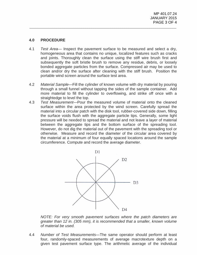
MP 401.07.24 JANUARY 2015
PAGE 3 OF 4 ____________________________________________________________________________
4.0 PROCEDURE 4.1 Test Area— Inspect the pavement surface to be measured and select a dry,
homogeneous area that contains no unique, localized features such as cracks and joints. Thoroughly clean the surface using the stiff wire brush first and subsequently the soft bristle brush to remove any residue, debris, or loosely bonded aggregate particles from the surface. Compressed air may be used to clean and/or dry the surface after cleaning with the stiff brush. Position the portable wind screen around the surface test area.
4.2 Material Sample—Fill the cylinder of known volume with dry material by pouring
through a small funnel without tapping the sides of the sample container. Add more material to fill the cylinder to overflowing, and strike off once with a straightedge to level the top.
4.3 Test Measurement—Pour the measured volume of material onto the cleaned surface within the area protected by the wind screen. Carefully spread the material into a circular patch with the disk tool, rubber-covered side down, filling the surface voids flush with the aggregate particle tips. Generally, some light pressure will be needed to spread the material and not leave a layer of material between the aggregate tips and the bottom surface of the spreading tool. However, do not dig the material out of the pavement with the spreading tool or otherwise. Measure and record the diameter of the circular area covered by the material at a minimum of four equally spaced locations around the sample circumference. Compute and record the average diameter.
NOTE: For very smooth pavement surfaces where the patch diameters are greater than 12 in. (305 mm), it is recommended that a smaller, known volume of material be used.
4.4 Number of Test Measurements—The same operator should perform at least
four, randomly-spaced measurements of average macrotexture depth on a given test pavement surface type. The arithmetic average of the individual

MP 401.07.24 JANUARY 2015
PAGE 4 OF 4 ____________________________________________________________________________
macrotexture depth values shall be considered to be the average macrotexture depth of the test pavement surface.
5.0 CALCULATION 5.1 Cylinder Volume—Calculate the internal volume of the sample cylinder as
follows:
V = 𝞹𝞹d 2 h 4
where:
V = internal cylinder volume, in.3 (mm3), d = internal cylinder diameter, in. (mm), and h = cylinder height, in. (mm).
5.2 Average Pavement Macrotexture Depth—Calculate the average pavement
macrotexture depth using the following equation:
AMTD = 4V 𝞹𝞹D2
where: AMTD = average texture depth of pavement macrotexture, in. (mm), V = sample volume, in.3 (mm3), and D = average diameter of the area covered by the material, in. (mm).
6.0 REPORT 6.1 The report for each pavement test surface shall contain data on the following
items: 6.1.1 Location and identification of test pavement surface. 6.1.2 Date. 6.1.3 Volume of material used for each test measurement, in.3 (mm3). 6.1.4 Number of test measurements. 6.1.5 Average diameter of the area covered by the material, in. (mm), for each test. 6.1.6 Average texture depth, in. (mm), for each test. 6.1.7 Average texture depth, in. (mm), for total pavement test surface.

MP 401.07.25 JANUARY 2015
WEST VIRGINIA DEPARTMENT OF TRANSPORTATION
DIVISION OF HIGHWAYS MATERIALS CONTROL, SOILS AND TESTING DIVISION
MATERIALS PROCEDURE
____________________________________________________________________
GUIDE FOR EVALUATION OF ASPHALT PAVEMENTS WITH SUBSTANDARD PROPERTIES
___________________________________________________________________________
1. PURPOSE
1.1 Provide a consistent approach and checklist for use by construction project personnel when evaluating asphalt pavement with substandard properties and aid in any subsequent decision.
1.2 Identify pavement factors and characteristics most critical to satisfactory performance.
1.3 Validate, if it is appropriate, the removal of the pavement in question.
2. SCOPE
2.1 This procedure shall be applicable to all newly placed Marshall and Superpave mix base layers and wearing courses.
2.2 All facets of construction including quality control, quality assurance, and independent
assurance sampling and testing, along with construction practices and methods, and observable distresses and defects in the finished mat should be considered when determining any action required to remediate the newly placed asphalt course(s). It is generally necessary to consider all facets when trying to determine the cause of substandard properties and observed distresses, and then decide on remedial action that needs to be executed.
3. REFERENCED DOCUMENTS
3.1 Special Provision Section 401, Asphaltic Base, Wearing, and Patching and Leveling Courses, original issuance February 2013.
3.2 Hot-Mix Asphalt Paving Handbook 2000 3.3 WVDOT/DOH Asphalt Field Technician Handbook
3.4 WVDOT/DOH Construction Manual
4.0 REVIEW OF PROJECT DOCUMENTATION 4.1 Procedures and guidelines for testing, recording data and calculating pay deductions
or otherwise are documented in our Standard Specifications and Materials Procedures. These steps are generally followed and in most cases done correctly.

MP 401.07.25 JANUARY 2015 PAGE 2 OF 11
____________________________________________________________________________
However, prior to deciding to remove and replace a particular section of asphalt pavement, the raw data yielding the substandard mixture properties should be examined. All applicable data, including sample/specimen mass and aggregate specific gravity, should be evaluated for obvious errors.
4.2 Quality Control Data 4.2.1 As per the requirements of the Division’s Standard Specifications and applicable
materials procedures, the contractor perform quality control testing to ensure the quality of the asphalt mixture produced. Depending on the particular timing and frequency, some quality control tests may fall near an acceptance test whose results revealed substandard mixture properties. In these cases, the results from the quality control test should be compared to the results from the acceptance test. While it is possible that materials or plant operations may change between quality control and acceptance tests, resulting in different mixture properties, the examination of quality control data may prove valuable in validating questionable property values.
4.3 Quality Assurance Testing 4.3.1 Depending on whether or not the same testing equipment was utilized, the similarity in
results between the contractor’s quality control tests and the Department’s verification or acceptance tests may vary. However, provided the results compare within the tolerances from the specifications, any substandard mixture properties from the acceptance test should be considered valid.
4.4 Independent Assurance Testing 4.4.1 For particular projects on the National Highway System, using a dedicated sample for
this purpose, Division personnel are required to compare results obtained with the sampling procedure and testing equipment used for the contractor’s quality control test. It is further required that Division personnel utilize different testing equipment than that used when testing for acceptance.
Depending on the sample selected for the comparison, some independent assurance tests may compare directly with, or fall near, an acceptance test whose results revealed substandard mixture properties. In these cases, the results from the independent assurance test should be compared to the results from the acceptance test. In most circumstances, the testing equipment will differ between the independent assurance test and the comparison test. However, for the sake of validating the questionable acceptance results, this comparison may prove helpful. Provided the results from the acceptance test and the independent assurance test are similar, comparing within the tolerances from the Standard Specifications, any substandard mixture properties from the acceptance test should be considered valid.
5.0 REVIEW OF PREVIOUS CONSTRUCTION LOTS 5.1 While it is possible that ingredient materials or plant operations may vary between
sublots of production and result in somewhat different mixture properties, the examination of test data or pavement performance for previously produced mixtures may prove useful in validating questionable property values. However, when performing such a comparison, it is extremely important to evaluate the component

MP 401.07.25 JANUARY 2015 PAGE 3 OF 11
____________________________________________________________________________
materials to ensure that the two mixtures, the previously produced material and the material with substandard properties under evaluation, are comprised of essentially the same ingredients and proportions.
5.2 When the similarity between the previously produced material and the material with
substandard properties has been verified, obvious errors in test results should become apparent. For example, if adjoining sections of pavement with similar levels of air voids (VTM) are performing in a significantly different manner, then one of the VTM test results from the two periods of production is likely incorrect. General instructions on reviews such as these are very difficult; performing such comparisons requires considerable experience and should be performed on a case-by-case basis. Familiarity with a particular aggregate, mixture, or mixing plant is invaluable in these instances.
6.0 REVIEW AND OBSERVATION OF TESTING PERSONNEL
6.1 The practices of the individuals responsible for the performance of the test and
documentation of the data that resulted in the substandard mixture properties may be observed. Although Asphalt Plant or Field Technicians are considered to be qualified to perform the corresponding quality-control, acceptance, or verification testing that identified the questionable material, an informal review of the procedures employed by the involved technicians may reveal an important deviation.
6.2 Also, as part of a continuing evaluation, it is often beneficial to routinely review the practices of all testing personnel to ensure that the proper sampling and testing techniques are being routinely utilized. The purpose of this exercise is to verify the continued competency of the involved technicians and thereby eliminate all doubt in this regard.
7. RE-EXAMINATION OF RETAINED MIXTURE SAMPLES
7.1 Loose asphalt mixture (Gmm samples) - Prior to deciding to remove and replace a particular section of asphalt pavement, all available mixture samples from the affected production should be analyzed. These samples include the loose asphalt mixture obtained for theoretical maximum specific gravity (Gmm) determination. The Gmm of an asphalt mixture is a very important property. This value influences asphalt binder content (AC) when “back-calculation from the Gmm” is selected as the method for AC determination. The Gmm value also affects the VTM and determines the daily target density which is used with roadway cores to determine the level of compaction achieved. It is critically important that the correct Gmm value be identified before deciding to remove and replace any pavement.
7.2. Superpave gyratory compactor (SGC) or Marshall compacted specimens - As stated
previously, it is absolutely necessary that all available mixture samples from the applicable period of asphalt mixture production be scrutinized prior to removing and replacing any questionable asphalt pavement. In addition to the Gmm samples, the bulk specific gravity (Gmb), determined from the compacted specimens, affects both the VTM and voids-in-the mineral aggregate (VMA). As with the Gmm determination, it is equally important that the correct Gmb value be identified before deciding to remove and replace any asphalt pavement.
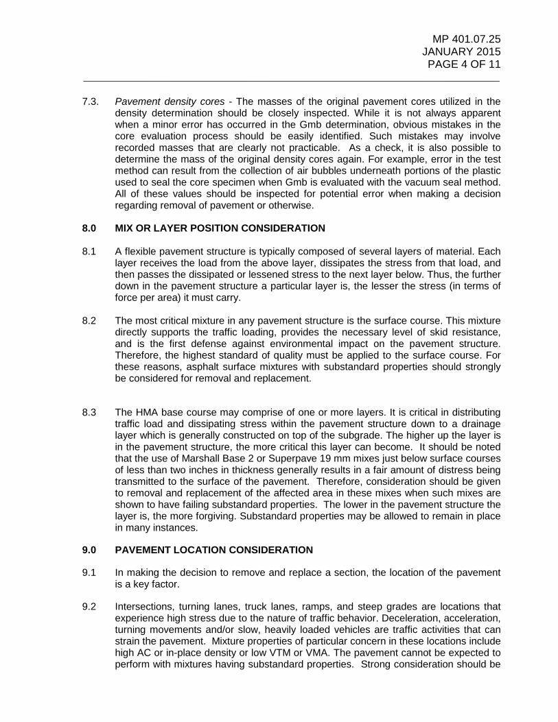
MP 401.07.25 JANUARY 2015 PAGE 4 OF 11
____________________________________________________________________________
7.3. Pavement density cores - The masses of the original pavement cores utilized in the density determination should be closely inspected. While it is not always apparent when a minor error has occurred in the Gmb determination, obvious mistakes in the core evaluation process should be easily identified. Such mistakes may involve recorded masses that are clearly not practicable. As a check, it is also possible to determine the mass of the original density cores again. For example, error in the test method can result from the collection of air bubbles underneath portions of the plastic used to seal the core specimen when Gmb is evaluated with the vacuum seal method. All of these values should be inspected for potential error when making a decision regarding removal of pavement or otherwise.
8.0 MIX OR LAYER POSITION CONSIDERATION
8.1 A flexible pavement structure is typically composed of several layers of material. Each
layer receives the load from the above layer, dissipates the stress from that load, and then passes the dissipated or lessened stress to the next layer below. Thus, the further down in the pavement structure a particular layer is, the lesser the stress (in terms of force per area) it must carry.
8.2 The most critical mixture in any pavement structure is the surface course. This mixture
directly supports the traffic loading, provides the necessary level of skid resistance, and is the first defense against environmental impact on the pavement structure. Therefore, the highest standard of quality must be applied to the surface course. For these reasons, asphalt surface mixtures with substandard properties should strongly be considered for removal and replacement.
8.3 The HMA base course may comprise of one or more layers. It is critical in distributing traffic load and dissipating stress within the pavement structure down to a drainage layer which is generally constructed on top of the subgrade. The higher up the layer is in the pavement structure, the more critical this layer can become. It should be noted that the use of Marshall Base 2 or Superpave 19 mm mixes just below surface courses of less than two inches in thickness generally results in a fair amount of distress being transmitted to the surface of the pavement. Therefore, consideration should be given to removal and replacement of the affected area in these mixes when such mixes are shown to have failing substandard properties. The lower in the pavement structure the layer is, the more forgiving. Substandard properties may be allowed to remain in place in many instances.
9.0 PAVEMENT LOCATION CONSIDERATION
9.1 In making the decision to remove and replace a section, the location of the pavement is a key factor.
9.2 Intersections, turning lanes, truck lanes, ramps, and steep grades are locations that experience high stress due to the nature of traffic behavior. Deceleration, acceleration, turning movements and/or slow, heavily loaded vehicles are traffic activities that can strain the pavement. Mixture properties of particular concern in these locations include high AC or in-place density or low VTM or VMA. The pavement cannot be expected to perform with mixtures having substandard properties. Strong consideration should be

MP 401.07.25 JANUARY 2015 PAGE 5 OF 11
____________________________________________________________________________
given to removal and replacement on high-speed facilities with heavy amounts of traffic loading.
10.0 PAVEMENT SURFACE APPEARANCE DEFECT CONSIDERATIONS
10.1 Flushing and Bleeding occur when the liquid asphalt cement comes to the top of the mix surface generally under traffic loading and are usually in the form of long streaks or strips along the wheel paths within the mat. Fat Spots are more isolated areas where liquid asphalt comes to the surface of the mix, but are not necessarily concentrated in the wheel paths. They can occur anywhere across the mat and generally occur during the laydown and compaction process, and in many cases result in very thick patches of free liquid asphalt on the surface of the mat. These characteristics may result from a high AC or in-place density, low VTM or VMA, or an excessively fine gradation. These types of distresses are serious in nature and not easily addressed with remedial treatments. Pavements in this condition often eventually rut, shove, and can present numerous safety concerns.
See the photos below for examples of flushing, bleeding, and fat spots.
Excessive Bleeding and Flushing along wheel paths in new asphalt pavement.

MP 401.07.25 JANUARY 2015 PAGE 6 OF 11
____________________________________________________________________________
Excessive Fat Spot in new asphalt pavement.
Additional guidance on the evaluation of and severity of flushing can be found in Special Provision for Section 401, Part 401.7.3 and use of MP 401.07.24.
10.1.1 The above defects are all indications of excess binder in the mix and should be considered for removal and replacement if the areas are large enough, occur in a pattern and affect a significant portion of the mix. Specifically, any flushing that extends more than about 30 feet in length and occurs in multiple locations as opposed to an isolated area is a cause for concern. Fat spots that are relatively small (less than approximately 12 inches in diameter) and occur only occasionally are not generally a concern. However, large fat spots (greater than 12 inches in diameter) and/or fat spots prevalent throughout the mat are a concern. The best action is to remove and replace the affected area.
10.2 Locations of rutting or shoving often occur corresponding to areas exhibiting flushing and bleeding. Again, these types of distresses are serious and present numerous safety concerns. Excessively deep pavement ruts can be a significant hazard to drivers. Along with a likely decreased skid resistance to begin with, water can pond in ruts and create a potential for vehicular hydroplaning and excessive spray, which can obscure a driver’s vision. Ponded water may also freeze in cold temperatures and result in the formation of ice.
10.2.1 Therefore, rutting that occurs within the first three months of service life and exceeds
¼ inch may be an indication of further rutting and should be monitored further. Additionally, rutting that occurs within the first three months of service life and exceeds ½ inch is considered a safety hazard and remediation is required. The best action is to remove and replace the affected area.

MP 401.07.25 JANUARY 2015 PAGE 7 OF 11
____________________________________________________________________________
Excessive rutting and shoving in new asphalt pavement. Note the displacement of the road lettering. Also note the presence of corresponding flushing of liquid asphalt.
10.3 A segregated mat can result from a number of factors ranging from the aggregate stockpiles at the asphalt mixing plant to the paving equipment at the project site. If segregation is widespread over several hundred feet of continuous pavement, removal and replacement of the affected area is probably the best option. When the segregated areas are discontinuous or “spotty,” removing and replacing various areas introduces a number of new construction joints. This scenario may often be less desirable than the original, segregated mat. In these cases, a fine-textured seal course is an option to consider for the affected locations.
Segregation in new asphalt pavement, Superpave 9.5 mm mix.

MP 401.07.25 JANUARY 2015 PAGE 8 OF 11
____________________________________________________________________________
Additional guidance on the evaluation of and severity of segregation can be found in Special Provision for Section 401, Part 401.7.3 and use of MP 401.07.24.
10.4 Raveling generally begins with the loss of surface fines or smaller aggregates, and then progresses to include larger aggregates sizes. It often occurs within a segregated mat after exposure to traffic and climate. For this reason, raveling is considered serious because some amount of coated aggregate has already been lost at the pavement surface, presenting more opportunity for moisture infiltration or premature oxidation.
Photo shows excessive raveling of pavement within an area of segregation during first year of service – 12.5 mm Superpave mix.
Photo showing close view of raveling from photo above.

MP 401.07.25 JANUARY 2015 PAGE 9 OF 11
____________________________________________________________________________
Photo shows advanced raveling and segregation of a Superpave 12.5 mm mix.
As with segregation, if the raveling is widespread and generally continuous, removal and replacement of the affected area is probably the best option. Excessive raveling and segregation can result in premature cracking of the asphalt pavement. However, when the raveled areas are discontinuous, removing and replacing various unconnected areas introduces a number of new construction joints. This scenario may often be less desirable than the original pavement. In these cases, a fine-textured seal course or micro surfacing may be an option to consider for the affected locations.
10.5 Tearing or pulling is another defect that can be found in newly placed mat. The mat can be torn or pulled by a paver that is traveling too fast, a paver with a screed that is worn or not heated properly, compacted by a roller that is traveling too fast or rolling a tender mix. The areas affected will have reduced density and are more susceptible to raveling and to the adverse effects of moisture. Depending on the severity of the tears, it may become a safety concern. The best option is to remove and replace the affected area.
Tear in new asphalt pavement. Note water stains along cracks. Area had been marked for repair.
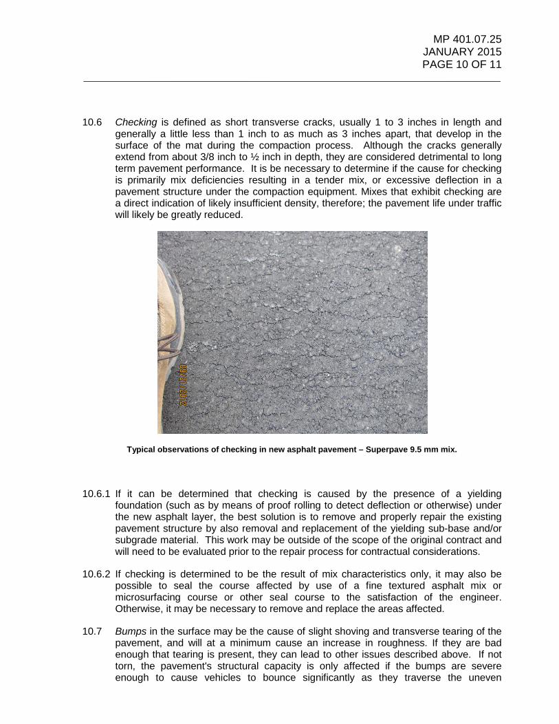
MP 401.07.25 JANUARY 2015 PAGE 10 OF 11
____________________________________________________________________________
10.6 Checking is defined as short transverse cracks, usually 1 to 3 inches in length and generally a little less than 1 inch to as much as 3 inches apart, that develop in the surface of the mat during the compaction process. Although the cracks generally extend from about 3/8 inch to ½ inch in depth, they are considered detrimental to long term pavement performance. It is be necessary to determine if the cause for checking is primarily mix deficiencies resulting in a tender mix, or excessive deflection in a pavement structure under the compaction equipment. Mixes that exhibit checking are a direct indication of likely insufficient density, therefore; the pavement life under traffic will likely be greatly reduced.
Typical observations of checking in new asphalt pavement – Superpave 9.5 mm mix.
10.6.1 If it can be determined that checking is caused by the presence of a yielding foundation (such as by means of proof rolling to detect deflection or otherwise) under the new asphalt layer, the best solution is to remove and properly repair the existing pavement structure by also removal and replacement of the yielding sub-base and/or subgrade material. This work may be outside of the scope of the original contract and will need to be evaluated prior to the repair process for contractual considerations.
10.6.2 If checking is determined to be the result of mix characteristics only, it may also be possible to seal the course affected by use of a fine textured asphalt mix or microsurfacing course or other seal course to the satisfaction of the engineer. Otherwise, it may be necessary to remove and replace the areas affected.
10.7 Bumps in the surface may be the cause of slight shoving and transverse tearing of the pavement, and will at a minimum cause an increase in roughness. If they are bad enough that tearing is present, they can lead to other issues described above. If not torn, the pavement's structural capacity is only affected if the bumps are severe enough to cause vehicles to bounce significantly as they traverse the uneven

MP 401.07.25 JANUARY 2015 PAGE 11 OF 11
____________________________________________________________________________
pavement. This would increase impact loading and thus increase the overall loading to which the pavement is subjected. In such severe cases, the likely best action is removal and replacement of the affected area.
Photo showing excessive transverse bumps and associated transverse tearing as well. This photo also shows longitudinal cracking in the center of the mat.

MP 401.13.50 JANUARY 2015
WEST VIRGINIA DEPARTMENT OF TRANSPORTATION DIVISION OF HIGHWAYS
MATERIALS CONTROL, SOILS AND TESTING DIVISION
MATERIALS PROCEDURE _________________________________________________________________________
GUIDE TO STATISTICAL ANALYSIS OF MATERIAL USING QUALITY LEVEL ANALYSIS-PERCENT WITHIN LIMITS
1.0 PURPOSE
1.1 The procedure described herein was developed in order to evaluate a set of test results and determine the Percent Within Limits (PWL) of the test results in accordance with Specification requirements.
2.0 SCOPE
2.1 This procedure is directly applicable to the Special Provision for Section 401 of the Standard Specifications, and the intent is to help determine pay factors for Asphaltic Pavement material as per the Special Provision. Please note that the resulting values for PWL determined with this procedure are affected by shifts in the arithmetic mean and by the sample standard deviation.
2.2 The resulting PWL values determined using this procedure are to be used to calculate pay factors as per the corresponding parts within Special Provision 401, Section 401.13 – Basis of Payment.
3.0 PROCEDURE
3.1 All sampling and testing shall be performed as specified in the appropriate AASHTO, ASTM, and WVDOH Materials Procedures as required. The PWL can be calculated when evaluating test results within a specification containing both upper and lower target values, or when evaluating test results within a specification containing a single target value. Calculations will done in accordance with the procedures outlined within AASHTO R-9, Standard Practice for Acceptance Sampling Plans for Highway Construction using Excel workbooks prepared by MCS&T and used for laboratory analysis and documentation of test results.

MP 401.13.50 JANUARY 2015
Page 2 of 9
4.0 CALCULATIONS
All rounding is to occur in the final PL and PU calculations. Sample rounding precision is listed in the table below.
4.1 Determine the arithmetic mean (X�) of the test results
𝑋𝑋 = Σ𝑥𝑥𝑛𝑛
Where:
𝑋𝑋 = arithmetic mean of test results Σx = sum of test results 𝑥𝑥 = individual test value, and 𝑛𝑛 = total number of test values.
4.2 Compute the sample standard deviation(s):
𝑠𝑠 = �𝑛𝑛Σ(𝑥𝑥2)−(Σ𝑥𝑥)2 𝑛𝑛(𝑛𝑛−1)
𝑠𝑠 = ((𝑛𝑛Σ(𝑥𝑥2) − (Σ𝑥𝑥)2)/(𝑛𝑛(𝑛𝑛 − 1)))1/2
Where:
𝑠𝑠 = sample standard deviation

MP 401.13.50 JANUARY 2015
Page 3 of 9
4.3 Compute the upper quality index (Qu):
Qu = 𝑈𝑈𝑈𝑈𝑈𝑈− 𝑋𝑋𝑠𝑠
Where:
Qu = upper quality index, and 𝑈𝑈𝑈𝑈𝑈𝑈R = upper specification limit
Mix or Pavement Criteria Rounding Precision
Upper Specification Limit (USL)
Mat Density (%) 0.00 97.0
Asphalt Binder Content (%) - mixes with NMAS 19 mm (3/4”) or less
0.00 Mix design target value + 0.4
Asphalt Binder Content (%) - mixes with NMAS 25 mm (1”) or greater.
0.00 Mix design target value + 0.5
Gradation Minus #200 (%) 0.0 Mix design target + 2.0.
Bond Strength (psi) 0. Min 100. psi

MP 401.13.50 JANUARY 2015
Page 4 of 9
4.4 Compute the lower quality index (QL):
QL = 𝑋𝑋−𝑈𝑈𝑈𝑈𝑈𝑈
𝑠𝑠
Where:
QL = lower quality index, and 𝑈𝑈𝑈𝑈𝑈𝑈R = lower specification limit = target value * minus allowable deviation on a low side.
Mix or Pavement Criteria Lower Specification Limit (LSL)
Mat Density (%) 91.5
Joint Density (%) 89.0
Bond Strength (psi) 100
Asphalt Binder Content (%) - mixes with NMAS 19 mm (3/4”) or less
Mix design target value - 0.4
Asphalt Binder Content (%) - mixes with NMAS 25 mm (1”) or greater.
Mix design target value - 0.5
Gradation Minus #200 (%) Mix design target - 2.0.
4.5 Compute the quality level:
𝑃𝑃𝑃𝑃𝑈𝑈 = (𝑃𝑃𝑢𝑢 + 𝑃𝑃𝑈𝑈) − 100
Where:
𝑃𝑃𝑃𝑃𝑈𝑈 = Percent Within Limit. 𝑃𝑃𝑢𝑢 = percent within the upper specification limit which corresponds to a given Qu from Table 1. 𝑃𝑃𝑈𝑈 = percent within the lower specification limit which corresponds to a given QL from Table 1.
Note: When a USL is not specified, Pu shall be 100, and when a LSL is not specified, PL shall be 100.
Round PWL to whole number

MP 401.13.50 JANUARY 2015
Page 5 of 9

MP 401.13.50 JANUARY 2015
Page 6 of 9
The following examples are shown for illustrative purposes only. All rounding shown below will not apply to formal calculations for project pay factors.
EXAMPLE 1 – Mat Density Evaluation
2,500 tons of asphaltic pavement are placed, and five equal sublots of material have been laid out in the field as per MP 401.07.21. A core for density analysis is removed from locations determined randomly and the resulting compaction percentage is determined for each individual sample. The individual values are shown below.
X1 = 91.10 X2 = 92.00 X3 = 92.80 X4 = 95.20 X5 = 96.00
• The sample average for the lot and the standard deviation are calculated as follows:
Xavg = (91.10 + 92.00 + 92.80 + 95.20 + 96.00)/5 = 93.40
Sample size, n = 5
S = 2.10
• Calculate the Quality Index values:
For mat density, USL = 97.00 and LSL = 91.50 QU = (97 – 93.4)/2.10 = 1.71 PU = 100 (From Table 1) QL = (93.4 – 91.5)/2.10 = 0.91 PL = 81 (From Table 1)
• Calculate PWL: PWL = (Pu + Pl) – 100 PWL = (100 + 81) – 100 = 81 • Pay Factor : As per Table 401.13.3.1, Pay factor = 0.5(PWL)+55
Pay Factor = 0.5(81)+55 = 95.5%
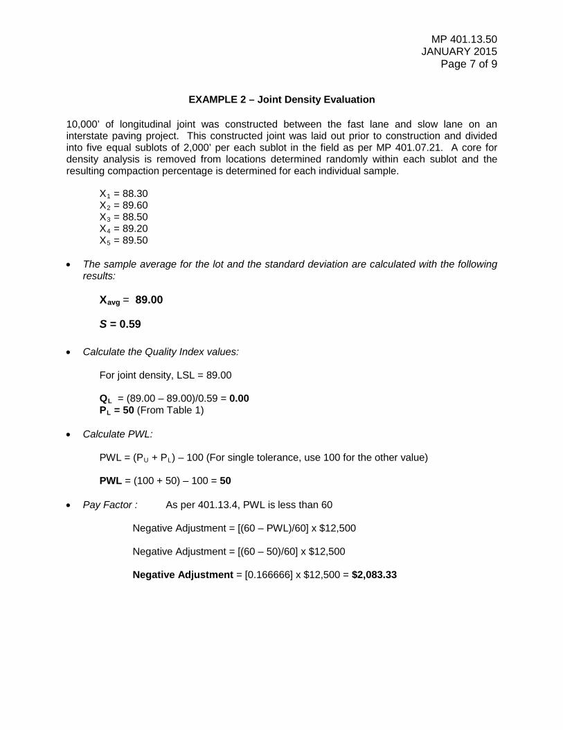
MP 401.13.50 JANUARY 2015
Page 7 of 9
EXAMPLE 2 – Joint Density Evaluation
10,000’ of longitudinal joint was constructed between the fast lane and slow lane on an interstate paving project. This constructed joint was laid out prior to construction and divided into five equal sublots of 2,000’ per each sublot in the field as per MP 401.07.21. A core for density analysis is removed from locations determined randomly within each sublot and the resulting compaction percentage is determined for each individual sample.
X1 = 88.30 X2 = 89.60 X3 = 88.50 X4 = 89.20 X5 = 89.50
• The sample average for the lot and the standard deviation are calculated with the following results:
Xavg = 89.00 S = 0.59
• Calculate the Quality Index values:
For joint density, LSL = 89.00 QL = (89.00 – 89.00)/0.59 = 0.00 PL = 50 (From Table 1)
• Calculate PWL: PWL = (PU + PL) – 100 (For single tolerance, use 100 for the other value) PWL = (100 + 50) – 100 = 50 • Pay Factor : As per 401.13.4, PWL is less than 60
Negative Adjustment = [(60 – PWL)/60] x $12,500 Negative Adjustment = [(60 – 50)/60] x $12,500 Negative Adjustment = [0.166666] x $12,500 = $2,083.33

MP 401.13.50 JANUARY 2015
Page 8 of 9
EXAMPLE 3 – Asphalt Content
2,500 tons of asphaltic pavement are placed, and five equal sublots of material have been laid out in the field as per MP 401.07.20. The mix being placed is a Superpave 9.5 mm mix with a design target of 6.5% AC. A loose sample for determination of asphalt binder content is removed from locations within each sublot and the resulting asphalt binder content is determined for each individual sample. The individual values are shown below.
X1 = 6.70 X2 = 6.90 X3 = 6.70 X4 = 6.90 X5 = 7.00
• The sample average for the lot and the standard deviation are calculated as follows:
Xavg = 6.84
Sample size, n = 5
S = 0.13
• Calculate the Quality Index values:
For AC, USL = 6.9 and LSL = 6.1 QU = (6.9 – 6.84)/0.13 = 0.46 PU = 67 (From Table 1) QL = (6.84 – 6.1)/0.13 = 5.69 PL = 100 (From Table 1)
• Calculate PWL: PWL = (Pu + Pl) – 100 PWL = (67 + 100) – 100 = 67 • Pay Factor : As per Table 401.13.3.2
Pay Factor = 55%

MP 401.13.50 JANUARY 2015
Page 9 of 9
EXAMPLE 4 - Gradation
2,500 tons of asphaltic pavement are placed, and five equal sublots of material have been laid out in the field as per MP 401.07.20. The mix being placed is a Superpave 9.5 mm mix with a design target of 6.4% on the #200 sieve. A loose sample for gradation is removed from locations within each sublot and the results for material finer than the #200 sieve are shown below.
X1 = 4.4 X2 = 5.3 X3 = 5.6 X4 = 5.9 X5 = 6.4
• The sample average for the lot and the standard deviation are calculated as follows:
Xavg = 5.52
Sample size, n = 5
S = 0.75
• Calculate the Quality Index values:
For #200 sieve, USL = 8.4 and LSL = 4.4 QU = (8.4 – 5.52)/0.75 = 3.84 PU = 100 (From Table 1) QL = (5.52 – 4.4)/0.75 = 1.49 PL = 96 (From Table 1)
• Calculate PWL: PWL = (Pu + Pl) – 100 PWL = (100 + 96) – 100 = 96 • Pay Factor : As per Table 401.13.3.2
Pay Factor = 96%
MP 700.00.05 ISSUED: APRIL 2014
WEST VIRGINIA DEPARTMENT OF TRANSPORTATION
DIVISION OF HIGHWAYS
MATERIALS CONTROL, SOILS AND TESTING DIVISION
MATERIALS PROCEDURE
GUIDE FOR SCHEDULING PAVEMENT
CORING FOR EVALUATION AND INVESTIGATION
1. PURPOSE
1.1 To establish a procedure to schedule pavement coring of new or existing pavement for the purpose of evaluation/investigation for West Virginia Division of Highways (WVDOH) projects.
2. SCOPE
2.1 This procedure shall apply to all Divisions and Districts of the WVDOH and Consultants that request pavement investigations for WVDOH projects.
3. REFERENCED DOCUMENTS
3.1 West Virginia Division of Highways, Standard Specifications Roads and Bridges
Section 401.7.4 – Thickness (Hot-Mix Asphalt Base, Wearing, and Patching and Leveling Courses)
Section 501.19 – Tolerance in Pavement Thickness (Portland Cement Concrete Pavement)
3.2 Materials Procedures
MP 401.07.21 – Sampling Compacted Asphaltic Mixtures from the Roadway
MP 401.07.22 – Standard Method of Measurement for Thickness of Asphalt Pavement Using Drilled Cores
MP 401.05.20 – Compaction Testing of Hot-Mix Asphalt Pavement
MP 721.21.26 – Procedure for Determining the Random Location Of Compaction Tests
3.3 Other Standard Documents

MP 700.00.05 ISSUED: April 2014
PAGE 2 OF 7 ____________________________________________________________________________
ASTM C42/C42M – Obtaining and Testing Drilled Cores […] of Concrete
4. PAVEMENT CORING REQUEST
4.1 The Requesting Engineer must provide to the Subsurface Investigation Group Supervisor and Pavement Engineer of Materials Control, Soils & Testing Division (MCS&T) the following information:
4.1.1 A current authorization number. Pavement coring will not commence until an authorization number is provided.
4.1.2 If it is determined that insufficient funds are available under the submitted authorization number, a formal request in writing must be submitted to the Director of MCS&T for pavement coring operations to commence.
4.1.3 A general description and overview of the requested project. This information must include the total number of cores with their locations and specified depths. Additionally, it must include the length of the project, width of mainline, shoulders, ramps, etc. the accessibility to water, and any features that could potentially require additional planning and equipment
4.1.4 When coring is to be performed on ongoing or new construction projects, sample locations are be in determined in accordance with MP 401.05.20 or MP 721.21.26 as well as specifications and regulations in line with the ongoing construction.
4.1.5 Specific sampling requests, including but not limited to; number of layers of pavement to be cored, desired core depth, and the type of testing required.
4.1.6 A detailed site map or project plans with detailed location markers including mile posts, stationing markers, bridge locations, and terminus.
4.1.7 Detailed project contact information, including Requesting Engineer and Project Supervisor phone number, and email.
4.1.8 Potential environmental concerns and special environmental instructions.
4.1.9 Specific instructions regarding project reclamation, if required.
4.1.10 A projected timeline in which the coring operations should be performed.
5. INTERAGENCY COORDINATION
5.1 The responsibility of the Requesting Engineer shall include:

MP 700.00.05 ISSUED: April 2014
PAGE 3 OF 7 ____________________________________________________________________________
5.1.1 Provide on-site coring locations. Project stationing should be marked at
intervals not to exceed 200 feet. All coring locations shall be clearly marked with high visibility paint. All coring locations shall be clearly labeled with the correct coring number and corresponding station\offset.
5.1.2 Appoint an inspector prior to layout of the on-site locations. The inspector will be responsible for verifying the onsite locations and observing the asphalt coring process. The inspector must also remain in contact with the Requesting Engineer throughout the coring process.
5.1.3 Obtain any required special permitting from local, state, or federal agencies.
5.1.4 Notify independent consultants and other agencies of the date of pavement coring commencement, as needed.
5.1.5 Complete list of requested laboratory testing on an MCS&T Form T-100.
5.1.6 In the case of expedited projects, scheduling and providing all necessary traffic control.
5.1.7 Coordination with the paving and/or general contractor for coring of ongoing construction projects.
5.2 The responsibility of the MCS&T Subsurface Investigation Group Supervisor shall include:
5.2.1 Schedule and provide all necessary traffic control. In the case of expedited projects, the Requesting Engineer will be responsible to schedule and provide traffic control.
5.2.2 Notify the Requesting Engineer of the date that pavement coring will commence.
5.2.3 Deliver the cores to the MCS&T laboratory for testing.
5.3 The responsibility of the MCS&T Pavement Engineer shall include:
5.3.1 Receive, store, and monitor all pavement cores delivered to the MCS&T Facility.
5.3.2 Contact the Requesting Engineer to review all pavement cores received at the MCS&T Laboratory.
5.3.3 Forward all laboratory test documentation to the Requesting Engineer.

MP 700.00.05 ISSUED: April 2014
PAGE 4 OF 7 ____________________________________________________________________________
6. PAVEMENT CORING PROCEDURE AND LABELING
6.1 Pavement Coring shall be performed in accordance with the following:
§ MP 401.07.21 § ASTM C42/C42M
6.2 All pavement cores and/or core bag samples will be clearly labeled with the
following information:
§ Project Number (Federal and State) § Project Authorization Number § Project Name § Driller’s Name § Date § Assigned core number § Location – Station, Offset
7. PAVEMENT CORE SAMPLE DELIVERY
7.1 The MCS&T Drilling Services will deliver all pavement core samples to the MCS&T Laboratory unless otherwise directed by the Requesting Engineer
8. PAVEMENT CORE SAMPLE RECEIVING
8.1 Upon delivery to the MCS&T Laboratory, the MCS&T Subsurface Investigation Group Supervisor will complete a Chain of Custody form (included in this MP) and submit the form to the MCS&T Pavement Engineer, or their representative for signature verifying custody and delivery of the cores.
8.2 Once the cores have been accepted into the correct laboratory, either the Pavement Engineer or the appropriate laboratory staff with complete the T100 testing request form or Site Manager Basic Sample Data Sheet and obtain a laboratory number (Sample ID) in accordance with the current procedures.
8.3 In the event that the pavement core samples are requested by the Engineer to be delivered to an alternate location, the Chain of Custody form will be forwarded to and signed by the Requesting Engineer. The pavement core samples from this time will be the responsibility of the Requesting Engineer. The signed Chain of Custody form will then be submitted to the MCS&T Pavement Engineer to verify custody transfer.

MP 700.00.05 ISSUED: April 2014
PAGE 5 OF 7 ____________________________________________________________________________
9. PAVEMENT CORE SAMPLE STORAGE
9.1 All pavement core samples delivered to the MCS&T Laboratory will be stored in an environmentally controlled facility to protect against excessive temperatures and moisture changes. All cores and/or core bag samples are to be labeled in accordance with Section 5.2 of this MP, in order to facilitate future identification for testing purposes. All samples will remain in storage until the samples have been reviewed by the Requesting Engineer and all laboratory testing has been completed.
10. PAVING CORE SAMPLE DISPOSAL
10.1 All paving core samples will be retained by the MCS&T Laboratory for a period of six months after the completion of laboratory testing and transmittal of a final report, unless other arrangements have been made. After six months MCS&T may dispose of the paving core samples unless otherwise requested in writing by the Requesting Engineer.
11. CONSULTANT SELECTION
11.1 In the event that the MCS&T Subsurface Investigation Group Supervisor determines that for any reason the MCS&T Drilling services cannot perform the pavement coring for the requested project, a consultant may be selected and used for drilling in accordance with the current consultant contract guidelines.
11.2 At the completion of project services, the Consultant will provide MCS&T with the following:
§ All cores and/or core bag samples that were collected, labeled in accordance with Section 5.2 of this MP
§ Any core logs and/or field reports § All test reports, if applicable
11.3 MCS&T will forward all project documentation to the Requesting Engineer for
final approval.
Aaron C. Gillispie, P.E. Director Materials Control Soils & Testing Division

MP 700.00.05 ISSUED: April 2014
PAGE 6 OF 7 ____________________________________________________________________________
WEST VIRGINIA DEPARTMENT OF TRANSPORTATION
DIVISION OF HIGHWAYS
MATERIALS CONTROL, SOILS AND TESTING DIVISION
____________________________________________________________________________
ASPHALT PAVEMENT CORING REQUEST FORM
Location of Project:
Please include the following Information:
□ Project Contact Information □ Detailed site drawings
□ Core Location Marked □ Traffic Control Coordinated Comments: Requesting District Approval Signature: Title: Date:
Project # Project Name
Authorization # Date Submitted
Requested By Project Contact (include phone #)
Project Details
Resurfacing or New
Construction
Design Thickness of pavement to be cored (Note if multiple lifts
are to be cored)
# of Cores required (As per 401.07.04)
Date Coring can commence
Latest date coring can be
completed

MP 700.00.05 ISSUED: April 2014
PAGE 7 OF 7 ____________________________________________________________________________
WEST VIRGINIA DEPARTMENT OF TRANSPORTATION
DIVISION OF HIGHWAYS
MATERIALS CONTROL, SOILS AND TESTING DIVISION
PAVEMENT CORING CHAIN OF CUSTODY
Notes:
Subsurface Investigation Group Supervisor:
Received By:
Project Number
Authorization Number
Project Name
Number of Cores
Number of Bag Samples
Driller
Date Drilled
Date Received

MP 601.03.50 ORIGINAL ISSUANCE: NOVEMBER 1976
REVISED: FEBRUARY 2018
WEST VIRGINIA DEPARTMENT OF TRANSPORTATION DIVISION OF HIGHWAYS
MATERIALS CONTROL, SOILS AND TESTING DIVISION
MATERIALS PROCEDURE
GUIDE FOR QUALITY CONTROL AND ACCEPTANCE REQUIREMENTS FOR PORTLAND CEMENT CONCRETE
1. PURPOSE
1.1 To establish minimum requirements for Contractor's Quality Control (QC) system and the Division's Acceptance Plan. It is intended that these minimum requirements be followed in detailing the inspection, sampling, and testing deemed necessary to maintain compliance with all specification requirements.
2. SCOPE
2.1 This Materials Procedure (MP) is applicable to all Portland Cement Concrete (PCC) items, and it outlines the quality control procedures for both plant and field operations and includes procedures for approving and using Master and/or Project Specific QC Plans. This procedure also aids in documentation and retention of QC Plans in ProjectWise.
3. GENERAL REQUIREMENTS
3.1 The Contractor shall provide and maintain a quality control system that will provide reasonable assurance that all materials and products submitted to the Division for acceptance will conform to the contract requirements whether manufactured or processed by the Contractor or procured from suppliers, subcontractors, or vendors. The contractor shall perform or have performed the inspections and tests required to substantiate product conformance to contract document requirements and shall also perform or have performed all inspections and tests otherwise required by the contract. The Contractor's quality control inspections and tests shall be documented and shall be available for review by the Engineer throughout the life of the contract. The Contractor shall maintain standard equipment and qualified personnel as required by the Specifications to assure conformance to contract requirements. Procedures will be subject to the review of the Division before the work is started.
4. QUALITY CONTROL PLAN
4.1 The contractor shall prepare a QC Plan detailing the type and frequency of inspection, sampling, and testing deemed necessary to measure and control the various properties of materials and construction governed by the Specifications. As a minimum, the

MP 601.03.50 ORIGINAL ISSUANCE: NOVEMBER 1976
REVISED: FEBRUARY 2018 PAGE 2 OF 9
sampling and testing plan should detail sampling location, sampling techniques, and test frequency to be utilized. Quality control sampling and testing performed by the Contractor may be utilized by the Division for acceptance.
A QC Plan must be developed by the Contractor and submitted to the Engineer prior 4.1.1to the start of construction on every project. Acceptance of the QC Plan by the Engineer will be contingent upon its concurrence with these guidelines.
As work progresses, an addendum(s) may be required to a QC Plan to keep the QC 4.1.2
program current. Personnel may be required to show proof of certification for testing. 4.2 Quality Control Plan Guidelines
The Plan shall identify the personnel responsible for the Contractor's quality control. 4.2.1This should include the company official who will act as the liaison with Division personnel, as well as the Certified Portland Cement Concrete Technician who will direct the inspection program at the plant or in the field depending if it is a plant or field QC Plan. Their phone number and email address must also be included as a means for contact by the Division personnel.
All classes of concrete and corresponding mix design numbers, which may be used, 4.2.2shall be listed on Plant QC Plan. All classes of concrete, which may be used, shall be listed on the Field QC Plan.
Process control sampling, testing, and inspection should be an integral part of the 4.2.3contractor's quality control system. In addition to the above requirements, the Contractor's QC Plan should document the process control requirements shown in Table 1 of Attachment 1. The process control activities shown in Table 1 are considered to be normal activities necessary to control the production and placing of a given product or material at an acceptable quality level. To facilitate the Division's activities, the Contractor, as per ML-25, shall retain all completed gradation samples until further disposition is designated by the Division.
All sampling and testing shall be in accordance with the methods and procedures 4.2.4required by the Specifications. Measuring and testing equipment shall be standard and properly calibrated as per the specified test procedures. If alternative sampling methods, procedures, and inspection equipment are to be used, they shall be detailed in the QC Plan.
4.2.4.1 Any individual who samples or tests either plastic or hardened concrete for quality control purposes shall be certified as a WVDOH PCC Inspector.
4.2.4.2 Any Laboratory which tests the hardened concrete for the Contractor, for quality control purposes, shall be listed in the Contractor’s QC Plan for field operations. This Laboratory shall provide evidence that it meets all of the applicable requirements in

MP 601.03.50 ORIGINAL ISSUANCE: NOVEMBER 1976
REVISED: FEBRUARY 2018 PAGE 3 OF 9
ASTM C1077 for a concrete testing laboratory, including curing facilities, testing equipment, technician proficiency, and recordkeeping. Each Laboratory shall be inspected and verified by either the Cement and Concrete Reference Laboratory (CCRL) or the applicable WVDOH District, and subsequent documentation shall be provided showing that the subject Laboratory and personnel meet the applicable requirements of ASTM C1077 for a concrete laboratory.
When calculating the compressive strength of concrete cylinders in accordance with 4.2.5AASHTO T22, the following procedure shall be used:
CS = ML 0.25 x π x D2
Where:
CS = Compressive Strength of the specimen ML = Maximum load carried by the specimen during the test π = Mathematical constant PI D = Diameter of the cylinder being tested (in accordance with AASTO T 22) Note: The calculation for CS shall be performed in one continuous step (without any
rounding), either by the testing machine, or by calculating device, and only the final value (CS) is permitted to be rounded (to the accuracy specified in AASHTO T 22). The value for π shall be the manufacturer’s pre-programmed value in a calculating device or the testing machine.
Miscellaneous Concrete: 4.2.6
The contractor is not required to perform the process control testing required by Part C of Table 1 of Attachment on miscellaneous concrete (as defined in section 4.2.6.1), provided that the concrete in question is being supplied by an A1 or A2 plant (as defined in IM-18), and provided that the requirements of section 4.2.6.2 are met for each project on which the reduced testing of miscellaneous concrete is applied.
4.2.6.1 Miscellaneous concrete shall be defined as relatively small quantities, not exceeding 25 yd3 (19 m3) per day, incorporated into items that will not adversely affect the traffic carrying capacity of a completed facility. Such items would not include any concrete intended for major structures, permanent mainline or ramp pavements, or any other structurally critical items.
The following items are suggested as a guideline in establishing items that may be categorized as miscellaneous concrete: Note: Concrete testing for certain items below is waived, in some cases, by the referenced section of the specifications.

MP 601.03.50 ORIGINAL ISSUANCE: NOVEMBER 1976
REVISED: FEBRUARY 2018 PAGE 4 OF 9
1 Sidewalks 2. Curb and Gutter 3. Slope walls for under drain outlet pipes 4. Temporary pavements and pipe crossings 5. Building floors 6. Slope paving and headers 7. Paved ditch or gutter 8. Guardrail anchorages (See section 715.12) 9. Metal pile shells (See section 614.5) 10. Small (less than 36" diameter) culvert headwalls 11. Fence posts (See section 715.12) 12. Catch basins, manhole bases, inlets, and junction boxes (and adjustments
of such items) not located in the roadway 13. Foundations for breakaway supports 14. Thrust blocks 15. Utility trench fills 16. Cast-in-place survey markers
4.2.6.2 One sample per two days of production (for the same project) shall be tested (beginning on the first day of production) for compressive strength, air content, and consistency. On a minimum of ten percent of the samples outlined above, the Division will observe the batching operation at the plant (that is producing the concrete to be sampled) and check the operational control.
4.2.6.3 When placing miscellaneous concrete and no testing is required, an Approved Source Sample will be generated in Site Manager. The C###### representing the test from the previous day of production shall be entered in the intended use field. Miscellaneous Concrete will be entered in remarks. Miscellaneous Concrete will be written on all batch tickets for which testing is not required, per the miscellaneous concrete provisions of this MP, prior to scanning and placing in ProjectWise.
Documentation: 4.2.7
The Contractor shall maintain adequate records of all inspections and tests. The records shall indicate the nature and number of observations made, the number and type of deficiencies found, the quantities approved and rejected, and the nature of corrective action taken as appropriate. The Contractor's documentation procedures will be subject to the review and approval of the Division prior to the start of the work and to compliance checks during the progress of the work.
Charts and Forms: 4.2.8
Chapman, Kelly A� 4/5/18 7:00 AMDeleted: Laboratory Reference Number 1345635 shall be used by the Division for documentation and acceptance purposes for quantities of concrete designated as miscellaneous concrete.
Mance, Michael A� 4/5/18 7:58 AMDeleted: c
Mance, Michael A� 4/5/18 7:58 AMDeleted: Laboratory Reference Number
Mance, Michael A� 4/5/18 7:24 AMComment [1]: Can’t “Miscellaneous Concrete” just be entered into the remarks instead of “Miscellaneous concrete Laboratory Reference Number”?
Mance, Michael A� 4/5/18 7:58 AMDeleted: Small Quantity
Chapman, Kelly A� 4/5/18 7:01 AMDeleted: The number 1345635
Mance, Michael A� 4/5/18 7:58 AMDeleted:
Mance, Michael A� 4/5/18 7:20 AMComment [2]: Can “Miscellaneous Concrete” be written on the first ticket instead of “Small Quantity”. The term “Small Quantity” may cause confusion, as that’s often associated with A-bar in concrete.
Mance, Michael A� 4/5/18 8:02 AMDeleted: the first

MP 601.03.50 ORIGINAL ISSUANCE: NOVEMBER 1976
REVISED: FEBRUARY 2018 PAGE 5 OF 9
All conforming and non-conforming inspections and test results shall be kept complete and shall be available at all times to the Division during the performance work. Forms shall be on a computer-acceptable medium where required. Batch ticket data shall be documented in accordance with the applicable section of MP 601.03.50, with a copy to be submitted to the District Materials Section within 72 hours of the concrete placement. Gradation data shall be documented on WVDOH form T300 using the material codes listed in the online computer systems user guide. The original gradation data shall be submitted to the District Materials Section within 72 hours of obtaining the gradation sample. Test data for Portland cement concrete shall be charted in accordance with the applicable requirements of MP 601.03.52. Gradation test data shall be plotted in accordance with the applicable requirements of MP 300.00.51. The Contractor may use other types of control charts as deemed appropriate by the Division. It is normally expected that testing and charting will be completed within 48 hours after sampling. The Contractor shall also ensure that all Material Suppliers prepare and submit the HL-441 form (weekly supplier report) in a timely manner
4.2.8.1 All charts and records documenting the Contractor's quality control inspections and tests shall become property of the Division upon completing of the work.
Batch Tickets 4.2.9
Each batch of Structural Concrete, including miscellaneous concrete (as defined in section 4.2.6.1), delivered at the project shall be accompanied by one batch ticket with all of the items of information listed in section 4.2.9.1 pre-printed on the ticket. In the case of Portland Cement Concrete Pavement, each batch of concrete delivered at the project on which a test in accordance with Table 1 of Attachment 1 is to be performed shall be accompanied by a batch ticket. This batch ticket shall have all of the items listed in section 4.2.9.1 pre-printed on the ticket unless non-agitator trucks or truck agitators are used. In this case, the batch ticket shall have all of the items listed in section 4.2.9.2 pre-printed on the ticket.
4.2.9.1 All batch tickets for Structural Concrete and Portland Cement Concrete Pavement Concrete transported by truck mixers shall have all of the following items pre- printed on the ticket: Producer/Supplier Code, Producer/Supplier Name, Producer/Supplier Location, Mix Design Laboratory Reference Number, Date, Sequence Number, Volume (yd3/m3), Time Batched, Time Unloaded, Contract Identification Number (CID #), Federal and/or State Project Number, Material Code, Material Name, Water Allowed (Gallon/Liter), Water at Plant (Gallon/Liter), Weight of Ice at Plant (lb/kg), Water at Job (Gallon/Liter), Weight of Cement (lb/kg), Weight(s) of Pozzolan(s) (lb/kg), Weight of Fine Aggregate (lb/kg), Weight of Coarse Aggregate (lb/kg), Admixture Name(s) and Weight(s) (ounces), Temperature (oF/oC), Cylinder I.D., Initial Counter, Final Counter, Target Consistency (in/mm), Actual Consistency (in/mm), Target Air (%), Actual Air (%), Truck Number.
Mance, Michael A� 4/5/18 7:33 AMDeleted: and
Mance, Michael A� 4/5/18 7:33 AMDeleted: (lbs)
Mance, Michael A� 4/5/18 7:35 AMDeleted: O
Mance, Michael A� 4/5/18 7:35 AMDeleted: (0.1)
Mance, Michael A� 4/5/18 7:37 AMDeleted: Ice (lbs),

MP 601.03.50 ORIGINAL ISSUANCE: NOVEMBER 1976
REVISED: FEBRUARY 2018 PAGE 6 OF 9
4.2.9.2 All batch tickets for concrete delivered by means of nonagitator trucks or truck
agitators shall have all of the following items pre-printed on the ticket: Producer/Supplier Name, Mix Design Laboratory Reference Number, Date, Sequence Number, Volume (yd3/m3), Time Batched, Time Unloaded, CID#, Federal and/or State Project Number, Material Code, Material Name, Water Allowed (Gallon/Liter), Water at Plant (Gallon/Liter), Weight of Ice at Plant (lb/kg), Weight of Cement (lb/kg), Weight of Pozzolan (lb/kg), Weight of Fine Aggregate (lb/kg), Weight of Coarse Aggregate (lb/kg), Admixture Name(s) and Weight(s) (ounces), Temperature (oF/oC), Target Consistency (in/mm), Actual Consistency (in/mm), Target Air (%), Actual Air (%), Truck Number.
4.2.9.3 The batch ticket in the case of either type of concrete shall be a pre-printed batch ticket prepared by the plant. This ticket may be either computer generated or a standard pre-printed form with blank spaces provided in which all of the required data shall be recorded. The data items listed above that are completed in the field (such as Time Unloaded, Actual Consistency, etc.) must have a space on the batch ticket for completion. Volume is to be reported to the nearest 0.01 yd3 (0.01 m3). Consistencies are to be reported to the nearest 0.25 inch (6 mm). Target and Actual Air are to be reported to the nearest 0.1% (to the nearest 0.25% if the volumetric method is used).
Corrective Action: 4.2.10
The Contractor shall take prompt action to correct conditions, which have resulted, or could result, in the submission to the Division of materials and products, which do not conform to the requirements of the Contract documents.
Non-Conforming Materials: 4.2.11
4.2.11.1 The contractor shall establish and maintain an effective and positive system for controlling non-conforming material, including procedures for its identification, isolation and disposition. Reclaiming or reworking of non-conforming materials shall be in accordance with procedures acceptable to the Division. All non- conforming materials and products shall be positively identified to prevent use, shipment, and intermingling with conforming materials and products. Holding areas, mutually agreeable to the Division and the Contractor shall be provided by the Contractor.
Types of QC Plans: 4.2.12
4.2.12.1 QC Plans which are intended for use on more than one project shall be defined as Master QC Plans. Section 4.3 outlines the procedures for Master QC Plan submittal and approval.
Mance, Michael A� 4/5/18 7:54 AMDeleted: and
Mance, Michael A� 4/5/18 7:54 AMDeleted: s
Mance, Michael A� 4/5/18 7:55 AMDeleted: O
Mance, Michael A� 4/5/18 7:55 AMDeleted: (0.1
Mance, Michael A� 4/5/18 7:55 AMDeleted: , Ice (lbs)

MP 601.03.50 ORIGINAL ISSUANCE: NOVEMBER 1976
REVISED: FEBRUARY 2018 PAGE 7 OF 9
4.2.12.2 QC Plans which are intended for use on a single project shall be defined as Project
Specific QC Plans. Project Specific QC Plans shall contain a cover letter which includes the following: project description, CID#, Federal and/or State Project Number.
4.2.12.3 A contractor may submit a Master QC Plan for Plant and/or Field operations instead of a Project Specific QC Plan.
4.2.12.4 Once any QC Plan is approved for a project, the key date shall be entered in Site Manager by the appropriate District Materials personnel. The first date entered shall be the date the Project QC Plan letter is received. The second date shall be when the district approves the QC Plan for use on the project.
4.3 Master QC Plan
The intent of Master QC Plans is to facilitate the approval process in a more uniform 4.3.1manner. Master QC Plans can be submitted to the Division by the Contractor when their workload in a given District is routinely repetitive for the year.
The Contractor shall submit a Master Field QC Plan yearly to each District in 4.3.2which they have work (see Attachment 2). If the Contractor does not have work in a given District for the year, then a Master Field QC Plan shall not be submitted to that District.
The Producer/Supplier shall submit a Master Plant QC Plan at the beginning of each 4.3.3
year to the District in which their plant is located (see Attachment 3).
The District will review the submitted Master QC Plans to see if they meet the 4.3.4applicable requirements of Sections 4.2 thru 4.2.11.1 and assign a Laboratory Reference Number to each QC Plan upon approval, for future referencing. The District will acknowledge approval of each Master QC Plan to the Contractor and/or Producer/Supplier by letter (see Attachment 4), which will include the Laboratory Reference Number and a copy of the approved Master QC Plan. This will then be scanned and placed in ProjectWise under the appropriate District’s Org for that Contractor and/or Producer/Supplier.
Once a project has been awarded, if a contractor elects to use the approved Master 4.3.5Plant and Master Field QC Plans on that project, the Contractor shall submit a letter requesting to use the Master QC Plans for that project. This letter must be on the Contractor’s letterhead paper, be addressed to the District Engineer/Manager or their designee, and contain the following information: project number, CID#, project description, type of Quality Control Plan and the laboratory reference number for the Master QC Plan. See Attachment 5 for an example of a plant letter and Attachment 6 for an example of a field letter.
MP 601.03.50 ORIGINAL ISSUANCE: NOVEMBER 1976
REVISED: FEBRUARY 2018 PAGE 8 OF 9
4.3.5.1 The District shall review the referenced Master QC Plans to ensure they cover all
items in that project. If the referenced Master QC Plan is found to be insufficient for some items on that project, the District shall request the Contractor to submit additional information for quality control of those items as an addendum on a project specific basis. When the District is satisfied with the QC Plan for that project, a letter shall be sent to the Contractor acknowledging approval (see Attachment 7), with the following attached: the contractor’s project QC Plan request letter and the Master QC Plan approval letter. This shall then be placed in the project’s incoming-mail mailbox in ProjectWise.
4.3.5.2 A Master QC Plan that has been approved for project use shall be good for the duration of that project.
4.3.5.3 For the use of Division Personnel, the District approval letter for this project must state the ProjectWise link to the referenced Master QC Plan for that Contractor (for example: WVDOT ORGS > District Organization #> Materials > Year > Master QC Plans).
The Master Field and Plant QC Plans shall be valid for the duration of one calendar 4.3.6year beginning on January 1st and ending on December 31st. The Master Plant QC Plan will also cover maintenance purchase order concrete for the year.
5. ACCEPTANCE SAMPLING AND TESTING
5.1 Acceptance sampling and testing is the responsibility of the Division. Quality control tests by the Contractor may be used for acceptance.
5.2 The Division shall sample and test for applicable items completely independent of the contractor at a frequency equal to approximately ten (10) percent of the frequency for testing given in the approved QC Plan. Witnessing the contractor’s sampling and testing activities may also be a part of the acceptance procedure, but only to the extent that such tests are considered “in addition to” the ten (10) percent independent tests.
5.3 Results from independent tests conducted by the Division for gradation, entrained air, consistency, and strength will be plotted on the Contractor's quality control charts with a red circle, but are not to be included in the moving average. When the Contractor's tests are witnessed, the results are circled on the control chart in red, and are to be included in the moving average calculations.

MP 601.03.50 ORIGINAL ISSUANCE: NOVEMBER 1976
REVISED: FEBRUARY 2018 PAGE 9 OF 9
5.4 Results from both independent tests and witnessed tests will be evaluated in
accordance with MP 700.00.54. If a dissimilarity is detected, an investigation shall be immediately initiated to determine the cause of the dissimilarity.
Ronald L. Stanevich, P.E. Director Materials Control, Soils & Testing Division
RLS:Fm Attachments

MP 601.03.50 ORIGINAL ISSUANCE: NOVEMBER 1976
REVISED: FEBRUARY 2018 ATTACHMENT 1
PAGE 1 OF 3
TABLE 1
CONTRACTORS PROCESS CONTROL REQUIREMENTS
STRUCTURAL CONCRETE AND PORTLAND CEMENT CONCRETE PAVEMENT
Minimum frequency* A. PLANT AND TRUCKS 1. Mixer Blades Prior to Start of Job and Weekly 2. Scales a. Tared Daily b. Calibrate Prior to start of Job c. Check Calibration Weekly 3. Gauges and Meters-Plant and Truck a. Calibrate Yearly b. Check Calibration Weekly 4. Admixture Dispenser a. Calibrate Prior to Start of Job b. Check Operation and Calibration Daily B. AGGREGATES 1. Fine Aggregate a. Gradation Per section 601.3.2.4 of the Specifications b. Moisture Daily

MP 601.03.50 ORIGINAL ISSUANCE: NOVEMBER 1976
REVISED: FEBRUARY 2018 ATTACHMENT 1
PAGE 2 OF 3 2. Coarse Aggregates a. Gradation Per section 601.3.2.4 of the Specifications b. Percent passing No. 75mm Daily c. Ā for Combined Coarse Aggregates Fine Aggregates and Cement Per section 601.3.2.4 of the Specifications d. Moisture Daily C. PLASTIC CONCRETE 1. Entrained Air Content Pavement Concrete Two at the beginning of the paving
operation, per Section 501.4.2, then one per 500 yd3 (380 m3) or fraction thereof, with a minimum of two per day
Structural Concrete One per 100 yd3 (75 m3) or fraction thereof, (except Bridge Superstructure) with a minimum of one per ½ day of operation
Bridge Superstructure One per batch 2. Consistency**
Pavement Concrete One per 500 yd3 (380 m3) or fraction thereof, with a minimum of two per day
Structural Concrete One per 100 yd3 (75 m3) or fraction thereof, (except Bridge Superstructure) with a minimum of one per ½ day of operation
Bridge Superstructure One for first batch and one for every fifth
batch thereafter 3. Temperature Per Specification

MP 601.03.50 ORIGINAL ISSUANCE: NOVEMBER 1976
REVISED: FEBRUARY 2018 ATTACHMENT 1
PAGE 3 OF 3 4. Yield
Pavement Concrete Per Section 501.3 of the Specifications and one for each five days of operation after the first five days of operation
Structural Concrete Per Section 601.3.2.3 of the Specifications
and one for each ten sets of cylinders after the first ten
5. Compressive Strength***
Pavement Concrete One set of concrete cylinders for each 350 yd3 (75 m3) or fraction thereof
Structural Concrete For each class concrete delivered and placed
on a calendar day from a single supplier, one set of concrete cylinders for each 100 yd3 (75 m3) or fraction thereof
6. Permeability Pavement Concrete N/A Structural Concrete Per Section 601.4.5 of the Specifications Specialized Concrete Overlays Per Section 679.2.2 of the Specifications * Frequency for Process Control will vary with the size and type of aggregate or mixture and
the batch-to-batch variability of the item. ** When superplasticizer is added to the concrete in the field, additional consistency testing is
required as per Section 601.3.2.1 of the Specifications. *** All cylinders shall be made, cured, and shipped to the Laboratory in accordance with
AASHTO T 23 and MP 601.04.20. They shall be tested in accordance with AASHTO T 22 and the applicable section of the Standard Specifications.

MP 601.03.50 ORIGINAL ISSUANCE: NOVEMBER 1976
REVISED: FEBRUARY 2018 ATTACHMENT 2
PAGE 1 OF 2 _______________________________________________________________________________
***Example***
COMPANY LETTERHEAD
Mr./Ms./Mrs. West Virginia Department of Highways District ___ Engineer/Manager ___________, WV ##### RE: Master PCC Field QC Plan Dear ___________________,
We are submitting our PCC Field Quality Control Plan, developed in accordance with Sections 501 and 601 of the (year) WVDOH Standard Specifications, the (year) WVDOH Supplemental Specifications, and MP 601.03.50. 1. The Quality Control program is under the direction of_____________________, who can be
contacted in Field/Office, by telephone number _____________, cell#__________________, and/or e-mail address __________________________.
2. Sampling and testing will be performed by qualified personnel as per WVDOH specifications
Section 106. 3. Class(es) of Concrete to be controlled are listed as follows: - All types Class A - All types Class B - All types Class C - All types Class D - All types Class K - All types Class H
- Etc. 4. All items in this QC Plan will be sampled at a minimum frequency as specified in Table 1 of
Attachment 1. We acknowledge that additional sampling may be required by the Division in addition to the minimum frequency stated.
5. All sampling and testing will be in accordance with the methods and procedures required by the specifications. All measuring and testing equipment shall be standard and properly calibrated as per the specified test procedure. (If alternative sampling methods, procedures and inspection equipment are to be used please state in detail what they are and how they will be utilized.)

MP 601.03.50 ORIGINAL ISSUANCE: NOVEMBER 1976
REVISED: FEBRUARY 2018 ATTACHMENT 2
PAGE 2 OF 2 _______________________________________________________________________________
6. Batch ticket data shall be documented in accordance with the applicable section of MP
601.03.50, with a copy to be submitted to the District Materials Section within 72 hours of the concrete placement.
7. Calculation of the compressive strength of concrete cylinders will be done as shown in Section
4.2.5 of MP 601.03.50. 8. Testing of Miscellaneous Concrete will be as specified in Section 4.2.6 and Sub-Sections 4.2.6.1
thru 4.2.6.3 of MP 601.03.50. 9. We will maintain adequate records of all inspection and tests. The records will indicate the type
of test, number of observations made, the amount and type of deficiency’s found, the quantities approved and rejected, and the nature of corrective actions taken as appropriate. Our documentation procedures will be subject to the review and approval of the Division prior to the start of the work and to compliance checks during the progression of the work.
10. Our company will take prompt action to correct conditions, which have resulted or could result,
in the submission to the Division/District of materials and products, which do not conform to the requirements of the contract documents.
11. Non-Conforming Materials -- State how you will establish an effective and positive system
for controlling non-conforming material. This shall include the following: - procedures for non-conforming material identification - isolation and disposition of this material
Reclaiming or reworking of non-conforming materials shall be in accordance with procedures acceptable to the Division.
Our company will specify and provide holding areas, which shall be mutually agreeable by the Division and Contractor.
Very Truly Yours, ____________________________ Company Official, Title

MP 601.03.50 ORIGINAL ISSUANCE: NOVEMBER 1976
REVISED: FEBRUARY 2018 ATTACHMENT 3
PAGE 1 OF 2 _______________________________________________________________________________
***Example***
COMPANY LETTERHEAD
Mr./Ms./Mrs. West Virginia Department of Highways District ___ Engineer/Manager ___________, WV ##### RE: Master PCC Plant QC Plan Dear ___________________,
We are submitting our PCC PLANT Quality Control Plan, developed in accordance with Sections 501 and 601 of the (year) WVDOH Standard Specifications, the (year) WVDOH Supplemental Specifications, and MP 601.03.50. 1. The Quality Control program is under the direction of_____________________, who can be
contacted in Field/Office, by telephone number _____________, cell#__________________, and/or e-mail address __________________________.
2. Sampling and testing will be performed by qualified personnel as per WVDOH specifications
Section 106. 3. The PCC Mix Designs and class of concrete to be controlled are listed below: Mix Design Number Class of Concrete 1. ####### Class B 2. 3. 4. Etc. 4. All items in this QC Plan will be sampled at a minimum frequency as specified in Table 1 of
Attachment. We acknowledge that additional sampling may be required by the Division in addition to the minimum frequency stated.
5. All sampling and testing will be in accordance with the methods and procedures required by the
specifications. All measuring and testing equipment shall be standard and properly calibrated as

MP 601.03.50 ORIGINAL ISSUANCE: NOVEMBER 1976
REVISED: FEBRUARY 2018 ATTACHMENT 3
PAGE 2 OF 2 _______________________________________________________________________________
per the specified test procedure. (If alternative sampling methods, procedures and inspection equipment are to be used please state in detail what they are and how they will be utilized.)
6. Charts and forms Our Company will make sure all conforming and non-conforming inspections and test
results shall be kept complete and shall be available at all times to the Division during the performance work. Forms shall be on a computer-acceptable medium where required. Gradation data shall be documented on WVDOH form T300 using the material codes listed in the online computer systems user guide. The original gradation data shall be submitted to the District Materials Section within 72 hours of obtaining the gradation sample. Test data for Portland cement concrete shall be charted in accordance with the applicable requirements of MP 601.03.52. Gradation test data shall be plotted in accordance with the applicable requirements of MP 300.00.51. We may use other types of control charts as deemed appropriate by Division. It is normally expected that testing and charting will be completed within 48 hours after sampling. Our Company shall also ensure that all Material Suppliers prepare and submit the HL-441 form (weekly supplier report) in a timely manner. All charts and records will be turned over to the Division upon completion of work for a given project.
7. State that batch tickets will conform to requirements of MP601.03.50 Section 4.3.9 and its
applicable subsections. 8. Our company will take prompt action to correct conditions, which have resulted or could result,
in the submission to the Division of materials and products, which do not conform to the requirements of the contract documents.
9. Non-Conforming Materials - State how you will establish an effective and positive system for
controlling non-conforming material. This shall include the following: - procedures for non-conforming material identification - isolation and disposition of this material Reclaiming or reworking of non-conforming materials shall be in accordance with procedures
acceptable to the Division. Our company will specify and provide holding areas, which shall be mutually agreeable by the
Division and Contractor.
Very Truly Yours, ____________________________ Company Official, Title

MP 601.03.50 ORIGINAL ISSUANCE: NOVEMBER 1976
REVISED: FEBRUARY 2018 ATTACHMENT 4
PAGE 1 OF 1 _______________________________________________________________________________
WVDOH District Master QCP Approval Letter
*** EXAMPLE *** WVDOH LETTERHEAD
ACME Company 20 First St. Somewhere, WV ##### RE: PCC Plant or PCC Field (whichever is applicable) Master QC Plan Description: (YEAR) P/S code: (only if a plant QCP)
Dear Sir,
Your Quality Control Plan (M#-#####) for _________________has been reviewed and found to be acceptable for the following items:
- All WVDOH approved Designs for PCC Classes of Concrete controlled by the referenced QC plan.
As work progresses throughout the season an addendum(s) may be required to this
QCP to keep the QC program current. Also note that personnel may be required to show proof of certification for testing. Please use Lab Reference # M#-###### when corresponding about this QC plan. Please make sure that all appropriate personnel have a copy of this plan in their possession.
Very truly yours,
_____________________ Name, Title

MP 601.03.50 ORIGINAL ISSUANCE: NOVEMBER 1976
REVISED: FEBRUARY 2018 ATTACHMENT 5
PAGE 1 OF 1 _______________________________________________________________________________
***Example***
COMPANY LETTERHEAD
Mr./Ms./Mrs. _______________________ WV Department of Highways District ___ Engineer/Manager __________, WV ##### RE: PCC Quality Control Plan for Plant ---- Project Federal Project No. ___________________________ State Project No. ___________________________ Contract ID No. __________________________ Description _____________________________
Dear Mr./Ms./Mrs. _____________________,
We would like to use our Producer/Supplier’s name Master PCC Plant QC Plan, reference number ______________ for the project referenced above. All PCC items on the referenced project are covered by the Master PCC Plant QC Plan. (if needed state the Special Provision and that the addendum is attached for Quality Control of Special Provision Item)
The Quality Control Plan is under the direction of _____________________________, ____________________(title), and will be the company’s contact representative to the Division of Highways District Materials and Construction Departments. He/She can be contacted in person at the plant, by telephone _______________________or at e-mail at ____________________________.
Very truly yours,
_______________________
Company Representative

MP 601.03.50 ORIGINAL ISSUANCE: NOVEMBER 1976
REVISED: FEBRUARY 2018 ATTACHMENT 6
PAGE 1 OF 1 _______________________________________________________________________________
***Example***
COMPANY LETTERHEAD
Mr./Ms./Mrs. _______________________ WV Department of Highways District ___ Engineer/Manager __________, WV ##### Re: PCC Quality Control Plan for Field ---- Project Federal Project No. _____________________________ State Project No. __________________________ Contract ID No. __________________________ Description _____________________________ Dear Mr./Ms./Mrs. _____________________,
We would like to use our approved Master PCC Field QC Plan, reference number ______________ for the project referenced above. All PCC items on the referenced project are covered by the Master PCC Field QC Plan. (if needed state the Special Provision and that the addendum is attached for Quality Control of Special Provision Item)
The Quality Control Plan is under the direction of _____________________________, ____________________(title), and will be the company’s contact representative to the Division of Highways District Materials and Construction Departments. He/She can be contacted in person at the plant, by telephone _______________________or at e-mail at ____________________________.
Very truly yours,
_______________________
Company Representative

MP 601.03.50 ORIGINAL ISSUANCE: NOVEMBER 1976
REVISED: FEBRUARY 2018 ATTACHMENT 7
PAGE 1 OF 1 _______________________________________________________________________________
WVDOH District Master QCP Approval Letter
*** EXAMPLE *** WVDOH LETTERHEAD
ACME Company 20 First St. Somewhere, WV ##### RE: PCC Field or PCC Plant (whichever is applicable) QC Plan Project CID#: ######## Fed/State Project #: NHPP- ## - ####-## Description: Falling Slide County: XXXXXXX P/S Code: (If a Plant) Dear Sir,
Your request to use Master Quality Control Plan (M# - ######) for PCC Plant or PCC Field (whichever is applicable) on the project referenced above, has been reviewed and found to be acceptable for the following items:
- All WVDOH approved designs and classes of PCC controlled by this QCP listed below: - Class B - Class B modified - Class K -etc.
As work progresses throughout this project an addendum(s) may be required to this QCP
to keep the QC program current. Please use M# - ###### when corresponding about this QC Plan. Also note that personnel may be required to show proof of certification for testing. Please make sure that all appropriate personnel have a copy of this plan in their possession.
For Division Reference: The Master Quality Control Plan can be reviewed in ProjectWise at the folder shown below:
WVDOT ORG>D0#>year>MASTER QC PLANS>Contractors or Plant>Company >folder>Name of file (i.e.: 2016 04 05 M#160001 PCC Plant QCP)
Very truly yours,
________________________________ Name, Title