Embed Size (px)
Citation preview

.S>,
Ä.S>,ä
Operating Instructions EN
G... GST, GFL, GKS/GKL, GKR, GSS
Gearboxes / geared motors

Please read these instructions before you start working!
Follow the enclosed safety instructions.0Abb. 0Tab. 0

Contents i
3Lenze • BA 12.0023 • 9.0
1 About this documentation 5. . . . . . . . . . . . . . . . . . . . . . . . . . . . . . . . . . . . . . . . . . . . . . . . . . . . . .
1.1 Document history 6. . . . . . . . . . . . . . . . . . . . . . . . . . . . . . . . . . . . . . . . . . . . . . . . . . . . .
1.2 Conventions used 7. . . . . . . . . . . . . . . . . . . . . . . . . . . . . . . . . . . . . . . . . . . . . . . . . . . . . .
1.3 Terminology used 7. . . . . . . . . . . . . . . . . . . . . . . . . . . . . . . . . . . . . . . . . . . . . . . . . . . . .
1.4 Notes used 8. . . . . . . . . . . . . . . . . . . . . . . . . . . . . . . . . . . . . . . . . . . . . . . . . . . . . . . . . . .
2 Safety instructions 9. . . . . . . . . . . . . . . . . . . . . . . . . . . . . . . . . . . . . . . . . . . . . . . . . . . . . . . . . . . . .
2.1 General safety instructions for drive components 9. . . . . . . . . . . . . . . . . . . . . . . . . . .
2.2 Application as directed 12. . . . . . . . . . . . . . . . . . . . . . . . . . . . . . . . . . . . . . . . . . . . . . . .
2.3 Foreseeable misuse 12. . . . . . . . . . . . . . . . . . . . . . . . . . . . . . . . . . . . . . . . . . . . . . . . . . . .
2.4 Residual hazards 13. . . . . . . . . . . . . . . . . . . . . . . . . . . . . . . . . . . . . . . . . . . . . . . . . . . . . .
2.5 Disposal 14. . . . . . . . . . . . . . . . . . . . . . . . . . . . . . . . . . . . . . . . . . . . . . . . . . . . . . . . . . . . . .
3 Product description 15. . . . . . . . . . . . . . . . . . . . . . . . . . . . . . . . . . . . . . . . . . . . . . . . . . . . . . . . . . . . .
3.1 Identification 15. . . . . . . . . . . . . . . . . . . . . . . . . . . . . . . . . . . . . . . . . . . . . . . . . . . . . . . . .
3.2 Product features 16. . . . . . . . . . . . . . . . . . . . . . . . . . . . . . . . . . . . . . . . . . . . . . . . . . . . . . .3.2.1 Nameplate 18. . . . . . . . . . . . . . . . . . . . . . . . . . . . . . . . . . . . . . . . . . . . . . . . . . .
3.2.2 Gearbox code 21. . . . . . . . . . . . . . . . . . . . . . . . . . . . . . . . . . . . . . . . . . . . . . . . .3.2.3 Encoder code 22. . . . . . . . . . . . . . . . . . . . . . . . . . . . . . . . . . . . . . . . . . . . . . . . .
3.3 Transport weights 23. . . . . . . . . . . . . . . . . . . . . . . . . . . . . . . . . . . . . . . . . . . . . . . . . . . . .
4 Technical data 24. . . . . . . . . . . . . . . . . . . . . . . . . . . . . . . . . . . . . . . . . . . . . . . . . . . . . . . . . . . . . . . . .
4.1 General data and operating conditions 24. . . . . . . . . . . . . . . . . . . . . . . . . . . . . . . . . .
5 Mechanical installation 25. . . . . . . . . . . . . . . . . . . . . . . . . . . . . . . . . . . . . . . . . . . . . . . . . . . . . . . . .
5.1 Transport equipment for gearboxes 25. . . . . . . . . . . . . . . . . . . . . . . . . . . . . . . . . . . . . .
5.2 Storage 27. . . . . . . . . . . . . . . . . . . . . . . . . . . . . . . . . . . . . . . . . . . . . . . . . . . . . . . . . . . . . .
5.2.1 Specification of the direction of rotation 28. . . . . . . . . . . . . . . . . . . . . . . . .
5.3 Mounting 28. . . . . . . . . . . . . . . . . . . . . . . . . . . . . . . . . . . . . . . . . . . . . . . . . . . . . . . . . . . .5.3.1 Preparation 28. . . . . . . . . . . . . . . . . . . . . . . . . . . . . . . . . . . . . . . . . . . . . . . . . .
5.3.2 General information about the assembly of drive systems 29. . . . . . . . . . .
5.3.3 Assembly of transmission elements on solid shafts 29. . . . . . . . . . . . . . . . .5.3.4 Attachment of motors to gearboxes with bearing housing
(input design N) 30. . . . . . . . . . . . . . . . . . . . . . . . . . . . . . . . . . . . . . . . . . . . . .5.3.5 Coupling hubs 31. . . . . . . . . . . . . . . . . . . . . . . . . . . . . . . . . . . . . . . . . . . . . . . .
5.3.6 Attachment of gearboxes with hollow shafts and keyway 33. . . . . . . . . . .5.3.7 Mounting the shrink disc with a rotating cover 35. . . . . . . . . . . . . . . . . . . .
5.3.8 Mounting the fixed cover 39. . . . . . . . . . . . . . . . . . . . . . . . . . . . . . . . . . . . . . .
5.3.9 Mounting the hoseproof hollow shaft cover 39. . . . . . . . . . . . . . . . . . . . . .5.3.10 Gearboxes with breathers 40. . . . . . . . . . . . . . . . . . . . . . . . . . . . . . . . . . . . . .
5.3.11 Breather position, oil filling screw and drain plug 41. . . . . . . . . . . . . . . . . .5.3.12 Gearbox with compensation container for mounting position C 52. . . . . .

Contentsi
4 Lenze • BA 12.0023 • 9.0
6 Electrical installation 53. . . . . . . . . . . . . . . . . . . . . . . . . . . . . . . . . . . . . . . . . . . . . . . . . . . . . . . . . . .
6.1 Motor connection 53. . . . . . . . . . . . . . . . . . . . . . . . . . . . . . . . . . . . . . . . . . . . . . . . . . . . .
6.2 Motor options 53. . . . . . . . . . . . . . . . . . . . . . . . . . . . . . . . . . . . . . . . . . . . . . . . . . . . . . . .
7 Commissioning and operation 54. . . . . . . . . . . . . . . . . . . . . . . . . . . . . . . . . . . . . . . . . . . . . . . . . . .
7.1 Before switching on 54. . . . . . . . . . . . . . . . . . . . . . . . . . . . . . . . . . . . . . . . . . . . . . . . . . .
7.2 During operation 54. . . . . . . . . . . . . . . . . . . . . . . . . . . . . . . . . . . . . . . . . . . . . . . . . . . . . .
8 Maintenance 55. . . . . . . . . . . . . . . . . . . . . . . . . . . . . . . . . . . . . . . . . . . . . . . . . . . . . . . . . . . . . . . . . .
8.1 Maintenance intervals 55. . . . . . . . . . . . . . . . . . . . . . . . . . . . . . . . . . . . . . . . . . . . . . . . . .
8.2 Maintenance operations 57. . . . . . . . . . . . . . . . . . . . . . . . . . . . . . . . . . . . . . . . . . . . . . . .
8.2.1 Opening the condensation drain hole 57. . . . . . . . . . . . . . . . . . . . . . . . . . . .8.2.2 Lubricate roller bearings 58. . . . . . . . . . . . . . . . . . . . . . . . . . . . . . . . . . . . . . .
8.2.3 Table of lubricants 59. . . . . . . . . . . . . . . . . . . . . . . . . . . . . . . . . . . . . . . . . . . .8.2.4 Replacing the lubricant 61. . . . . . . . . . . . . . . . . . . . . . . . . . . . . . . . . . . . . . . . .
8.2.5 Lubricant quantity 62. . . . . . . . . . . . . . . . . . . . . . . . . . . . . . . . . . . . . . . . . . . . .8.2.6 Lubricant amounts for combinable mounting positions 68. . . . . . . . . . . . .
8.3 Repair 69. . . . . . . . . . . . . . . . . . . . . . . . . . . . . . . . . . . . . . . . . . . . . . . . . . . . . . . . . . . . . . .
8.7 Spare parts list for gearedmotors 70. . . . . . . . . . . . . . . . . . . . . . . . . . . . . . . . . . . . . . . .
8.8 Spare parts list for gearboxes and gearboxes with variable speed drives 71. . . . . . .
8.6 Order form 72. . . . . . . . . . . . . . . . . . . . . . . . . . . . . . . . . . . . . . . . . . . . . . . . . . . . . . . . . . .
9 Troubleshooting and fault elimination 73. . . . . . . . . . . . . . . . . . . . . . . . . . . . . . . . . . . . . . . . . . . .
About this documentation 1
5Lenze • BA 12.0023 • 9.0
1 About this documentation
Contents
• This documentation serves for safety-relevant operations on and with thegearboxes. It contains safety instructions which must be observed.
• All personnel working on and with the gearboxes must have the documentationavailable during the work and observe the information and notes relevant forthem.
• The documentation must always be complete and in a perfectly readable state.
Tip!Information and tools concerning the Lenze products can be found in thedownload area at
www.lenze.com
Validity
This documentation applies to the gearbox types:
Type NameGSTGFLGKS/GKLGKRGSS
Helical gearboxShaft-mounted helical gearboxHelical-bevel gearboxBevel gearboxHelical-worm gearbox
Target group
This documentation is directed at qualified skilled personnel according to IEC 60364.
Qualifiedskilledpersonnelarepersonswhohavetherequiredqualificationstocarryoutall activities involved in installing, mounting, commissioning, and operating theproduct.
About this documentationDocument history
1
6 Lenze • BA 12.0023 • 9.0
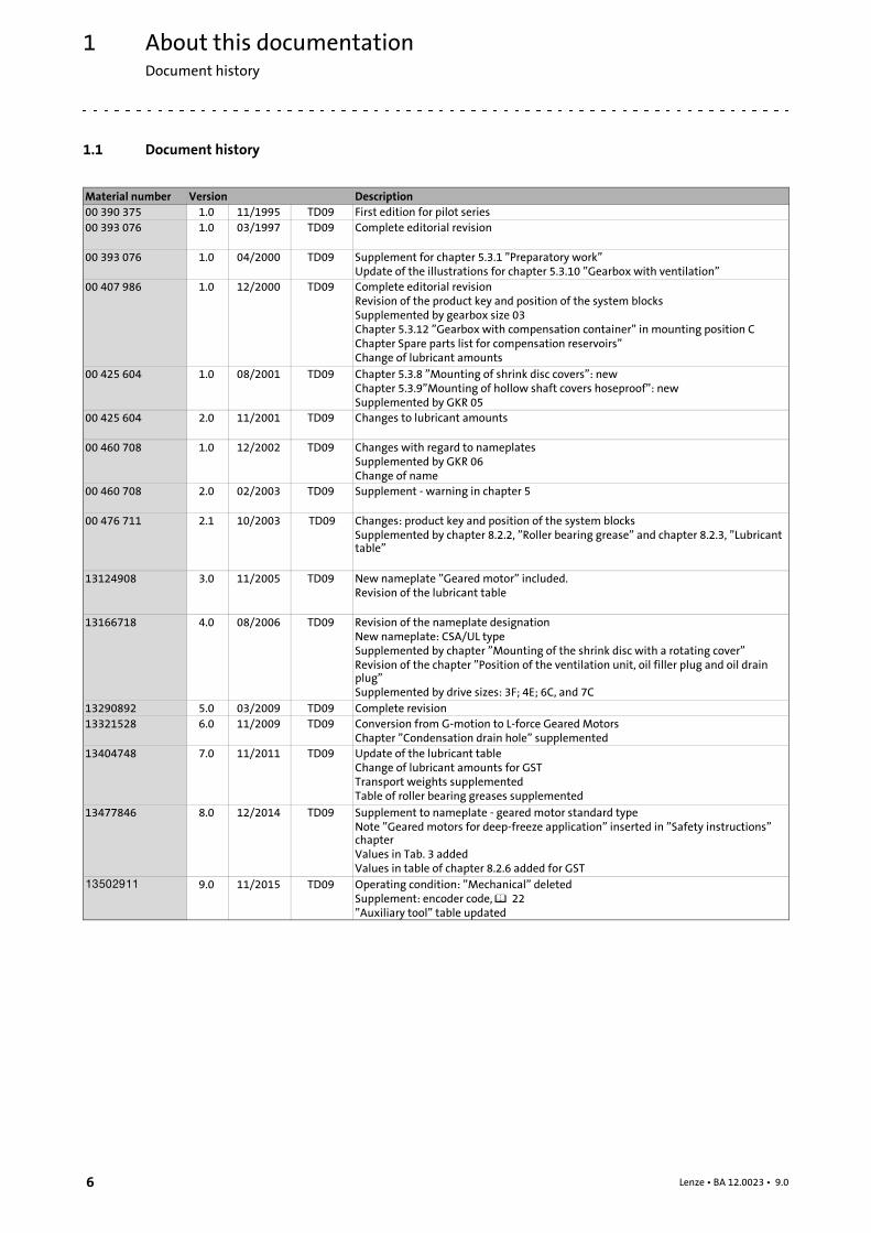
1.1 Document history
Material number Version Description00 390 375 1.0 11/1995 TD09 First edition for pilot series00 393 076 1.0 03/1997 TD09 Complete editorial revision
00 393 076 1.0 04/2000 TD09 Supplement for chapter 5.3.1 ”Preparatory work”Update of the illustrations for chapter 5.3.10 ”Gearbox with ventilation”
00 407 986 1.0 12/2000 TD09 Complete editorial revisionRevision of the product key and position of the system blocksSupplemented by gearbox size 03Chapter 5.3.12 ”Gearbox with compensation container” in mounting position CChapter Spare parts list for compensation reservoirs”Change of lubricant amounts
00 425 604 1.0 08/2001 TD09 Chapter 5.3.8 ”Mounting of shrink disc covers”: newChapter 5.3.9”Mounting of hollow shaft covers hoseproof”: newSupplemented by GKR 05
00 425 604 2.0 11/2001 TD09 Changes to lubricant amounts
00 460 708 1.0 12/2002 TD09 Changes with regard to nameplatesSupplemented by GKR 06Change of name
00 460 708 2.0 02/2003 TD09 Supplement - warning in chapter 5
00 476 711 2.1 10/2003 TD09 Changes: product key and position of the system blocksSupplemented by chapter 8.2.2, ”Roller bearing grease” and chapter 8.2.3, ”Lubricanttable”
13124908 3.0 11/2005 TD09 New nameplate ”Geared motor” included.Revision of the lubricant table
13166718 4.0 08/2006 TD09 Revision of the nameplate designationNew nameplate: CSA/UL typeSupplemented by chapter ”Mounting of the shrink disc with a rotating cover”Revision of the chapter ”Position of the ventilation unit, oil filler plug and oil drainplug”Supplemented by drive sizes: 3F; 4E; 6C, and 7C
13290892 5.0 03/2009 TD09 Complete revision13321528 6.0 11/2009 TD09 Conversion from G-motion to L-force Geared Motors
Chapter ”Condensation drain hole” supplemented13404748 7.0 11/2011 TD09 Update of the lubricant table
Change of lubricant amounts for GSTTransport weights supplementedTable of roller bearing greases supplemented
13477846 8.0 12/2014 TD09 Supplement to nameplate - geared motor standard typeNote ”Geared motors for deep-freeze application” inserted in ”Safety instructions”chapterValues in Tab. 3 addedValues in table of chapter 8.2.6 added for GST
.S>, 9.0 11/2015 TD09 Operating condition: ”Mechanical” deletedSupplement: encoder code, 22”Auxiliary tool” table updated
About this documentationConventions used
1
7Lenze • BA 12.0023 • 9.0
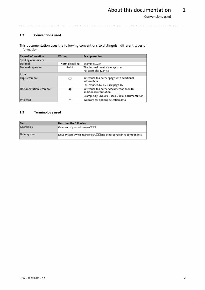
1.2 Conventions used
This documentation uses the following conventions to distinguish different types ofinformation:
Type of information Writing Example/notesSpelling of numbersDecimal Normal spelling Example: 1234Decimal separator Point The decimal point is always used.
For example: 1234.56IconsPage reference Reference to another page with additional
informationFor instance: 16 = see page 16
Documentation reference Reference to another documentation withadditional informationExample: EDKxxx = see EDKxxx documentation
Wildcard Wildcard for options, selection data
1.3 Terminology used
Term Describes the followingGearboxes Gearbox of product range G
Drive system Drive systems with gearboxes Gand other Lenze drive components
About this documentationNotes used
1
8 Lenze • BA 12.0023 • 9.0
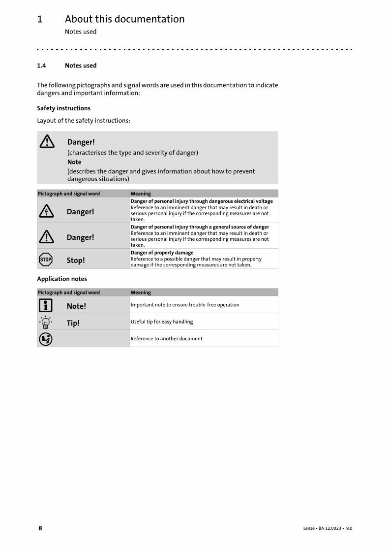
1.4 Notes used
The following pictographs and signalwords are used in this documentation to indicatedangers and important information:
Safety instructions
Layout of the safety instructions:
Danger!(characterises the type and severity of danger)
Note(describes the danger and gives information about how to preventdangerous situations)
Pictograph and signal word Meaning
Danger!
Danger of personal injury through dangerous electrical voltageReference to an imminent danger that may result in death orserious personal injury if the corresponding measures are nottaken.
Danger!
Danger of personal injury through a general source of dangerReference to an imminent danger that may result in death orserious personal injury if the corresponding measures are nottaken.
Stop!Danger of property damageReference to a possible danger that may result in propertydamage if the corresponding measures are not taken.
Application notes
Pictograph and signal word Meaning
Note! Important note to ensure trouble-free operation
Tip! Useful tip for easy handling
Reference to another document

Safety instructionsGeneral safety instructions for drive components
2
9Lenze • BA 12.0023 • 9.0
2 Safety instructions
2.1 General safety instructions for drive components
(in compliance with Low-Voltage Directive 2006/95/EC)
At the time of dispatch, the drive components are in linewith the latest state of the artand can be regarded as operationally safe.
Scope
The following general safety instructions apply to all Lenze drive and automationcomponents.
Theproduct-specific safety andapplicationnotes given in this documentationmust beobserved!
General hazards
Danger!Disregarding the following basic safety measures may lead to severepersonal injury and damage to material assets!
• Lenze drive and automation components ...
... must only be used for the intended purpose.
... must never be operated if damaged.
... must never be subjected to technical modifications.
... must never be operated unless completely assembled.
... must never be operated without the covers/guards.
... can -dependingontheirdegreeofprotection -have live,movableor rotatingpartsduring or after operation. Surfaces can be hot.
• All specifications of the corresponding enclosed documentation must beobserved.
This is vital for safe and trouble-free operation and for achieving the specifiedproduct features.
• Only qualified skilled personnel are permitted to work with or on Lenze drive andautomation components.
According to IEC 60364 or CENELEC HD 384, these are persons ...
... whoare familiarwith the installation, assembly, commissioningandoperationofthe product,
... possess the appropriate qualifications for their work,
... and are acquainted with and can apply all the accident prevent regulations,directives and laws applicable at the place of use.
Safety instructionsGeneral safety instructions for drive components
2
10 Lenze • BA 12.0023 • 9.0
Temperatures
The permissible temperature range is determined by the following:
• The lubricant specifications in connection with the expected oil temperatures inoperation (see chapter 8.1 and nameplate).
• The thermal class of the motor considering the motor temperature expectedduring operation (see nameplate and/or Operating Instructions of the motor).
The operating temperature is determined by the power loss, the ambient temperatureand the cooling system!
Stop!With mineral oil, the upper temperature limit for continuous operation is80°C, with synthetic oil and shaft sealing rings made of FP (Viton) 100°C.If these temperatures are exceeded, measures are necessary to reducethe temperature, see chapter 9.
Danger!Depending on the operating conditions, surfaces may be hot, provideprotection against accidental contact.
Ambient media
• Gearboxes are protected against dust and spray water.
• Motors according to their enclosure (see nameplate and/or Operating Instructionsfor the motor).
• Ambient media - especially chemically aggressive - can destroy shaft seals andcoatings (plastic). Abrasive media endanger shaft seals.
• The installation site of the drive must be free of shocks and vibration.
• Dirt of dust deposits impede the heat dissipation (cooling).
Transport, storage
• Transport and storage in a dry, low-vibration environment without aggressiveatmosphere; preferably in the packaging provided by the manufacturer.
– Protect against dust and impacts.
– Observe climatic conditions according to the technical data.
• Use load carrying equipment for transport! ( 25)
Before transport
• check that all component parts are safely mounted;
• check that all component parts with a loose fastening are secured or removed;
• tighten all transport aids (eye bolts or support plates).
Use an appropriate means of transport and lifting equipment! ( 25)
Safety instructionsGeneral safety instructions for drive components
2
11Lenze • BA 12.0023 • 9.0
If you do not install the motor immediately, ensure proper storage conditions.
• Up to one year:
– Shafts and uncoated surfaces are delivered in a protected against rust status.Aftertreatment is required where the corrosion protection has been damaged.
– Remove the plug for motors with condensation drain holes (special version).
• More than one year, up to two years:
– Apply a long-term corrosion preventive (e.g. Anticorit BW 366 from the Fuchscompany) to the shafts and uncoated surfaces before storing the motor away.
Corrosion protection
Lenze offers paintswith different resistance characteristics for drive systems. Since theresistancemay be reducedwhen the paint coat is damaged, defects in paint work (e.g.through transport or assembly) must be removed professionally to reach the requiredcorrosion resistance.
Mechanical installation
• Provide for careful handling and avoid mechanical overload. During handlingneither bend components, nor change the insulation distances.
Electrical installation
• Carry out the electrical installation according to the relevant regulations (e. g.cable cross-sections, fusing, connection to the PE conductor). Additional notes areincluded in the documentation.
• The Instructions contain notes concerning wiring according to EMC regulations(shielding, earthing, filters and cable routing). The compliance with limit valuesrequired by the EMC legislation is the responsibility of the manufacturer of themachine or system.
Warning:The inverters are automation componentswhich canbeused in industrialenvironment according to EN 61000-6-4. These products may cause radiointerference in residential areas. If this happens, the operator may need to takeappropriate action.
• Only plug in or remove pluggable terminals in the deenergised state!
Commissioning
• If required, you have to equip the systemwith additional monitoring andprotective devices in accordance with the respective valid safety regulations (e. g.law on technical equipment, regulations for the prevention of accidents).
• Before commissioning remove transport locking devices and keep them for latertransports.
Safety instructionsApplication as directed
2
12 Lenze • BA 12.0023 • 9.0
Geared motors for deep-freeze applications
• Geared motors for deep-freeze applications are specially optimised to operationat very low temperatures. Observe that for operation outside the temperaturerange specified (e.g. during commissioning) increased wear or even failures mayoccur.
• We recommend loading the gearbox with a maximum of 50 % of the rated outputtorque if it is outside the specified temperature range during commissioning.
2.2 Application as directed
All products which this documentation applies to are no household appliances but areexclusively intended as components for re-utilisation for commercial use orprofessional use in terms of IEC/EN 61000-3-2. They meet the requirements of theLow-VoltageDirective 2006/95/ECand the requirements of theharmonised standardsof the IEC/EN 60034 series.
Only use theproducts under the operating conditions andpower limits specified in thisdocumentation.
Donotusethebrakes installedasfail-safebrakes. It cannotberuledoutthatthebrakingtorque is reduced by disruptive factors which cannot be influenced.
• Drives
– ... must only be operated under the operating conditions and power limitsspecified in this documentation.
– ... comply with the protection requirements of the EU Low-Voltage Directive.
Any other use shall be deemed inappropriate!
2.3 Foreseeable misuse
• Do not operate the motors
– ... in explosion-protected areas
– ... in aggressive environments (acid, gas, vapour, dust, oil)
– ... in water
– ... in radiation environments
Note!Increased surface and corrosion protection can be achieved by usingadapted coating systems.
Safety instructionsResidual hazards
2
13Lenze • BA 12.0023 • 9.0
2.4 Residual hazards
Protection of persons
• Risk of burnst!
– Hot surfaces up to 140 °C during operation! Provide protection against contact.
• High-frequency voltages can be capacitively transferred to the motor housingthrough the inverter supply.
– Earth motor housing carefully.
• Risk of injury due to rotating shaft!
– Before working on the motor ensure that the motor is at standstill.
• Danger of unintentional starting or electrical shocks!
– Connections must only be made when the equipment is deenergised and themotor is at standstill.
– Installed brakes are no fail-safe brakes.
• Dangerous voltages at the power terminals, even if the plug is removed: residualvoltage >60 V!
Motor protection
• Installed thermal detectors do not offer full protection to the machine.
– If required, limit the maximum current, parameterise the inverter so that it willbe switched off after some seconds of operation with I > IN, especially if there isthe danger of blocking.
– Installed overload protection does not prevent an overload under anyconditions.
• Installed brakes are no fail-safe brakes.
– The torque can be reduced due to disruptive factors that cannot be influenced,e.g. by ingressing oil due to a defect shaft sealing ring on the A side.
• Fuses are no motor protection.
– Use current-dependent motor protection switches at an average operatingfrequency.
– Use installed thermal detectors at a high operating frequency.
• Excessive torques lead to a break of the motor shaft or demagnetisation.
– The maximum torques according to catalogue must not be exceeded.
• Lateral forces from the motor shaft may occur.
– Align shafts of motor and driving machine exactly to each other.
• If deviations from normal operation occur, e.g. increased temperature, noise,vibration, determine the cause and, if necessary, contact the manufacturer. If indoubt, switch off the motor.
• Design with plug:
– Never disconnect plug when energised! Otherwise, the plug can be destroyed.
– Switch off power supply and inhibit controller prior to disconnecting the plug.
Safety instructionsDisposal
2
14 Lenze • BA 12.0023 • 9.0
Fire protection
• Fire hazard
– Prevent contact with flammable substances.
2.5 Disposal
Sort individual parts according to their properties. Dispose of them as specified by thecurrent national regulations.
Product descriptionIdentification
3
15Lenze • BA 12.0023 • 9.0
3 Product description
• The most important technical data is given on the nameplate.
• The product catalogues contain further technical data.
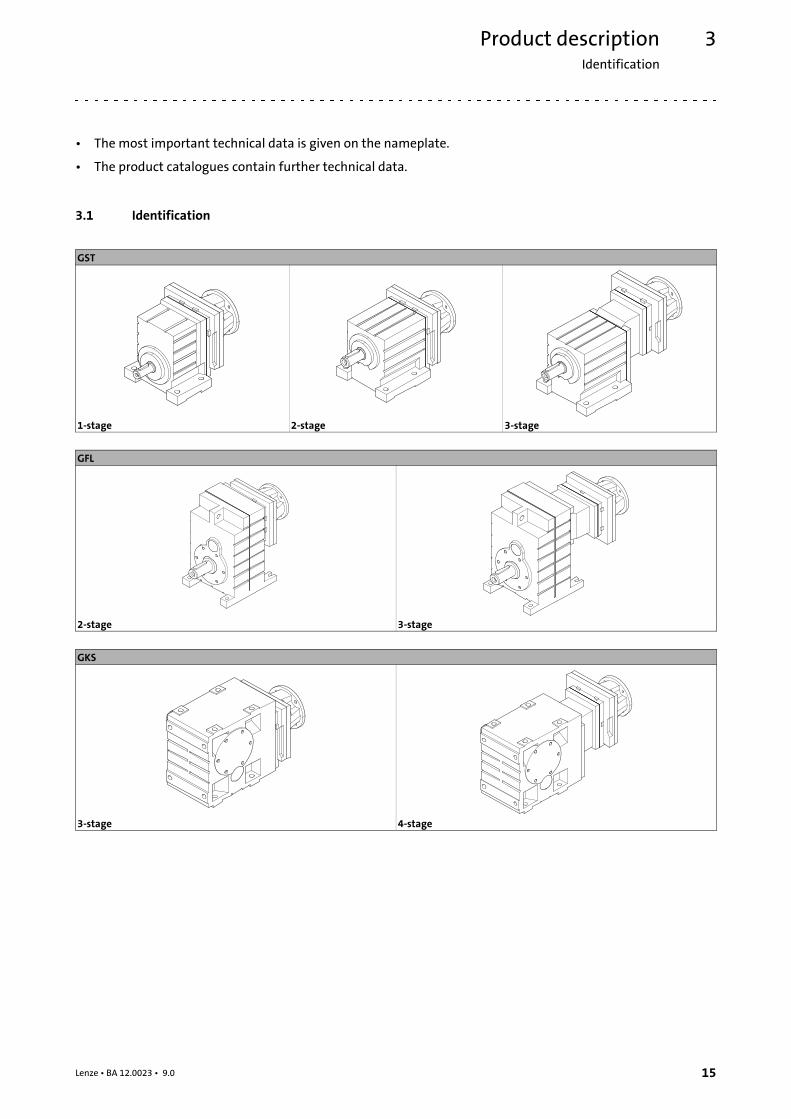
3.1 Identification
GST
1-stage 2-stage 3-stage
GFL
2-stage 3-stage
GKS
3-stage 4-stage
Product descriptionProduct features
3
16 Lenze • BA 12.0023 • 9.0
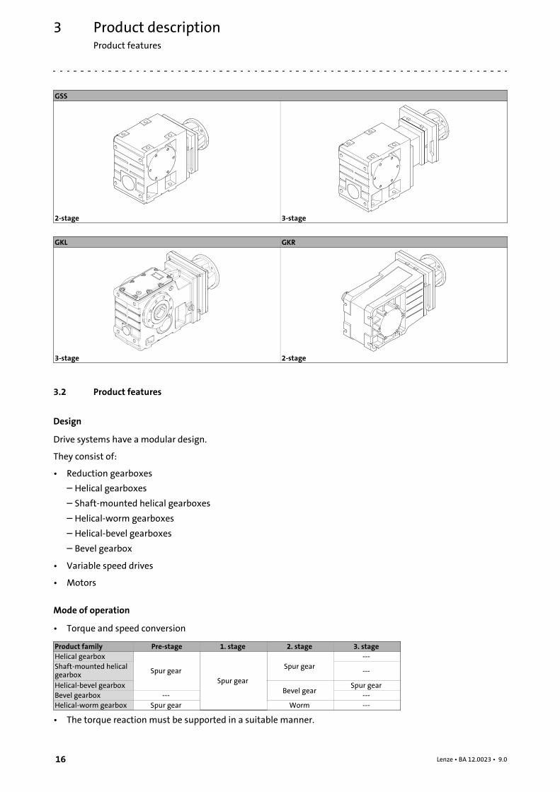
GSS
2-stage 3-stage
GKL GKR
3-stage 2-stage
3.2 Product features
Design
Drive systems have a modular design.
They consist of:
• Reduction gearboxes
– Helical gearboxes
– Shaft-mounted helical gearboxes
– Helical-worm gearboxes
– Helical-bevel gearboxes
– Bevel gearbox
• Variable speed drives
• Motors
Mode of operation
• Torque and speed conversion
Product family Pre-stage 1. stage 2. stage 3. stageHelical gearbox
Spur gearSpur gear
Spur gear---
Shaft-mounted helicalgearbox ---
Helical-bevel gearboxBevel gear
Spur gearBevel gearbox --- ---Helical-worm gearbox Spur gear Worm ---
• The torque reaction must be supported in a suitable manner.

Product descriptionProduct features
3
17Lenze • BA 12.0023 • 9.0
Mounting position (A-F) and position of systemmodules (1-6)
GST Terminal box, Motec, plug: 2, 3, 4, 5Without terminal box, Motec, plug: 0
A B C D E F
GFL Solid shaft: 6Hollow shaft: 0Hollow shaft with shrink disc: 1, 6
Foot: 3, 4Without foot: 0
Terminal box, Motec, plug: 2, 3, 4, 5Without terminal box, Motec, plug: 0
A B C D E F
GKS/GSS/GKL Solid shaft: 3, 5, 8 (3+5)Hollow shaft: 0Hollow shaft with shrink disc: 3, 5
Flange: 3, 5, 8 (3+5)Without flange: 0
Terminal box, Motec, plug: 2, 3, 4, 5Without terminal box, Motec, plug: 0
A B C D E F
GKR Solid shaft: 3, 5, 8 (3+5)Hollow shaft: 0Hollow shaft with shrink disc: 3, 5
Flange: 3, 5, 8 (3+5)Without flange: 0
Terminal box, Motec, plug: 2, 3, 4, 5Without terminal box, Motec, plug: 0
A B C D E F
Product description
Nameplate
3
18 Lenze • BA 12.0023 • 9.0
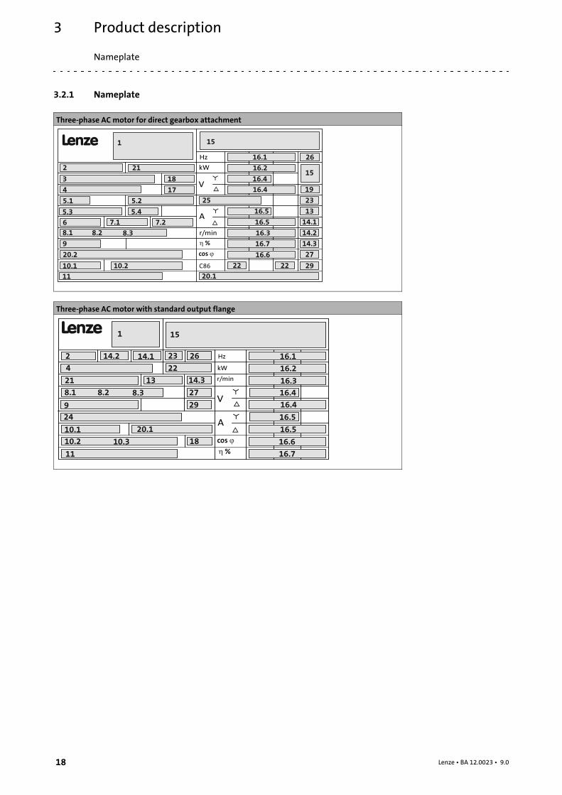
3.2.1 Nameplate
Three-phase AC motor for direct gearbox attachment
L
C86
cos �
Hz
kW
r/min
V
A
1
16.1
16.2
16.3
10.1
8.1
15
8.2 8.3
11
16.4
16.5
16.6
16.4
16.5
� %
10.2
9
2
3
4
6 7.1 7.2
5.1
5.3
5.2
5.4
18
25
27
14.3
14.2
14.1
13
23
16.7
22 22
26
19
15
29
17
21
20.2
20.1
Three-phase AC motor with standard output flange
L
� %
cos �
Hz
kW
r/min
V
A
9
2
1
4
16.1
16.2
16.3
10.1
9
22
8.1
24
18
14.2
15
21
8.2 8.3
23 2614.1
11
10.2 10.3
16.4
16.5
16.6
16.7
29
27
14.3
16.4
16.5
13
20.1
Product description
Nameplate
3
19Lenze • BA 12.0023 • 9.0
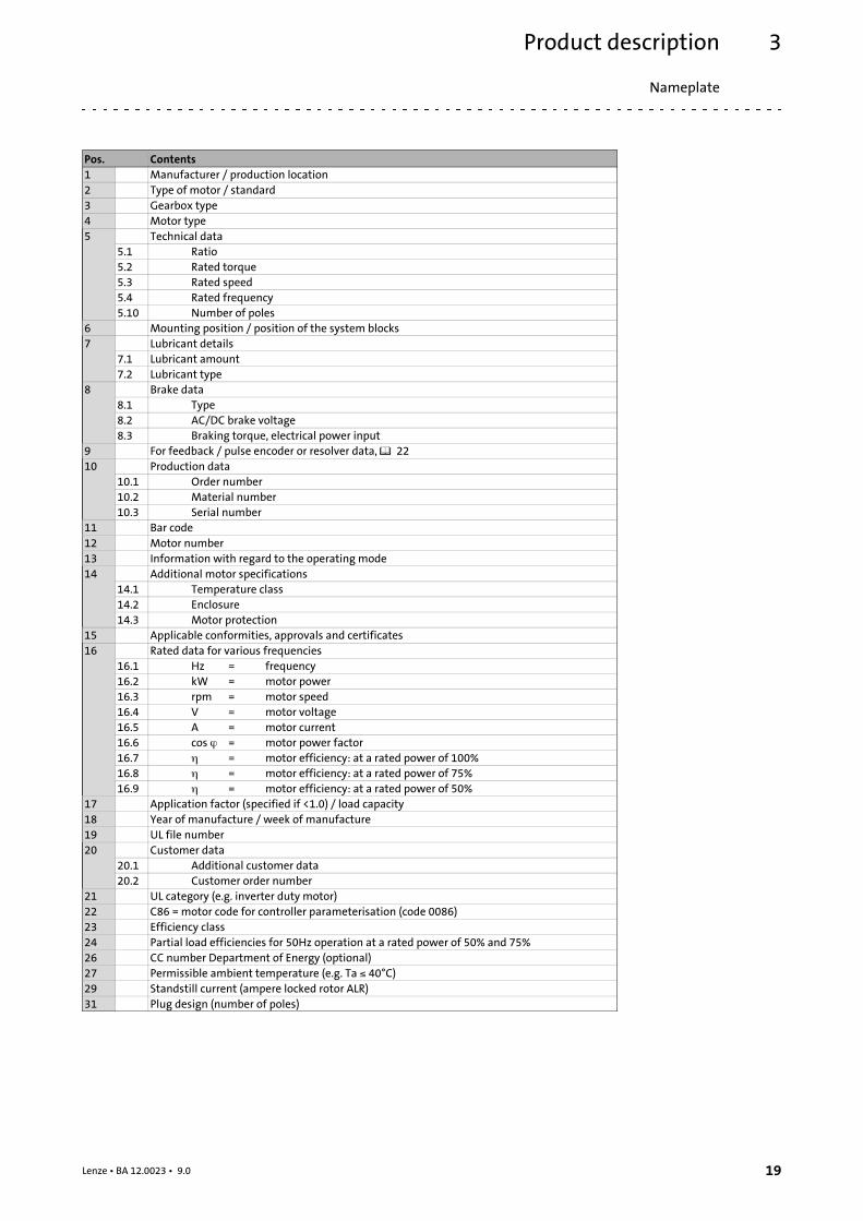
Pos. Contents1 Manufacturer / production location2 Type of motor / standard3 Gearbox type4 Motor type5 Technical data
5.1 Ratio5.2 Rated torque5.3 Rated speed5.4 Rated frequency5.10 Number of poles
6 Mounting position / position of the system blocks7 Lubricant details
7.1 Lubricant amount7.2 Lubricant type
8 Brake data8.1 Type8.2 AC/DC brake voltage8.3 Braking torque, electrical power input
9 For feedback / pulse encoder or resolver data, 2210 Production data
10.1 Order number10.2 Material number10.3 Serial number
11 Bar code12 Motor number13 Information with regard to the operating mode14 Additional motor specifications
14.1 Temperature class14.2 Enclosure14.3 Motor protection
15 Applicable conformities, approvals and certificates16 Rated data for various frequencies
16.1 Hz = frequency16.2 kW = motor power16.3 rpm = motor speed16.4 V = motor voltage16.5 A = motor current16.6 cos = motor power factor16.7 = motor efficiency: at a rated power of 100%16.8 = motor efficiency: at a rated power of 75%16.9 = motor efficiency: at a rated power of 50%
17 Application factor (specified if <1.0) / load capacity18 Year of manufacture / week of manufacture19 UL file number20 Customer data
20.1 Additional customer data20.2 Customer order number
21 UL category (e.g. inverter duty motor)22 C86 = motor code for controller parameterisation (code 0086)23 Efficiency class24 Partial load efficiencies for 50Hz operation at a rated power of 50% and 75%26 CC number Department of Energy (optional)27 Permissible ambient temperature (e.g. Ta 40°C)29 Standstill current (ampere locked rotor ALR)31 Plug design (number of poles)
Product description3
20 Lenze • BA 12.0023 • 9.0
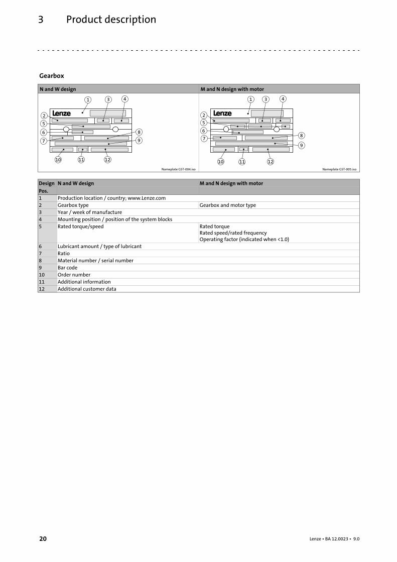
Gearbox
N andW design M and N design with motor
Nameplate GST-004.iso Nameplate GST-005.iso
Design N andW design M and N design with motorPos.1 Production location / country; www.Lenze.com2 Gearbox type Gearbox and motor type3 Year / week of manufacture4 Mounting position / position of the system blocks5 Rated torque/speed Rated torque
Rated speed/rated frequencyOperating factor (indicated when <1.0)
6 Lubricant amount / type of lubricant7 Ratio8 Material number / serial number9 Bar code10 Order number11 Additional information12 Additional customer data
Product description
Gearbox code
3
21Lenze • BA 12.0023 • 9.0
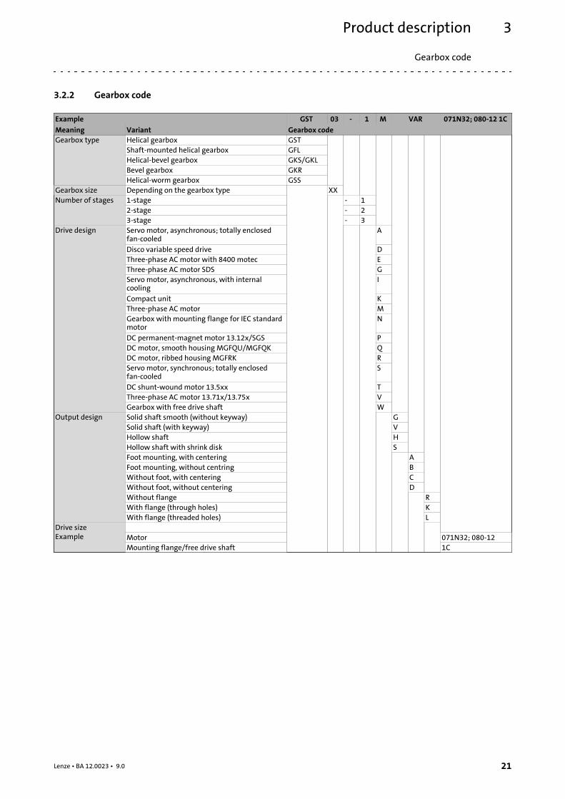
3.2.2 Gearbox code
Example GST 03 - 1 M VAR 071N32; 080-12 1C
Meaning Variant Gearbox codeGearbox type Helical gearbox GST
Shaft-mounted helical gearbox GFLHelical-bevel gearbox GKS/GKLBevel gearbox GKRHelical-worm gearbox GSS
Gearbox size Depending on the gearbox type XXNumber of stages 1-stage - 1
2-stage - 23-stage - 3
Drive design Servo motor, asynchronous; totally enclosedfan-cooled
A
Disco variable speed drive DThree-phase AC motor with 8400 motec EThree-phase AC motor SDS GServo motor, asynchronous, with internalcooling
I
Compact unit KThree-phase AC motor MGearbox with mounting flange for IEC standardmotor
N
DC permanent-magnet motor 13.12x/SGS PDC motor, smooth housing MGFQU/MGFQK QDCmotor, ribbed housing MGFRK RServo motor, synchronous; totally enclosedfan-cooled
S
DC shunt-wound motor 13.5xx TThree-phase AC motor 13.71x/13.75x VGearbox with free drive shaft W
Output design Solid shaft smooth (without keyway) GSolid shaft (with keyway) VHollow shaft HHollow shaft with shrink disk SFoot mounting, with centering AFoot mounting, without centring BWithout foot, with centering CWithout foot, without centering DWithout flange RWith flange (through holes) KWith flange (threaded holes) L
Drive sizeExample Motor 071N32; 080-12
Mounting flange/free drive shaft 1C
Product description
Encoder code
3
22 Lenze • BA 12.0023 • 9.0
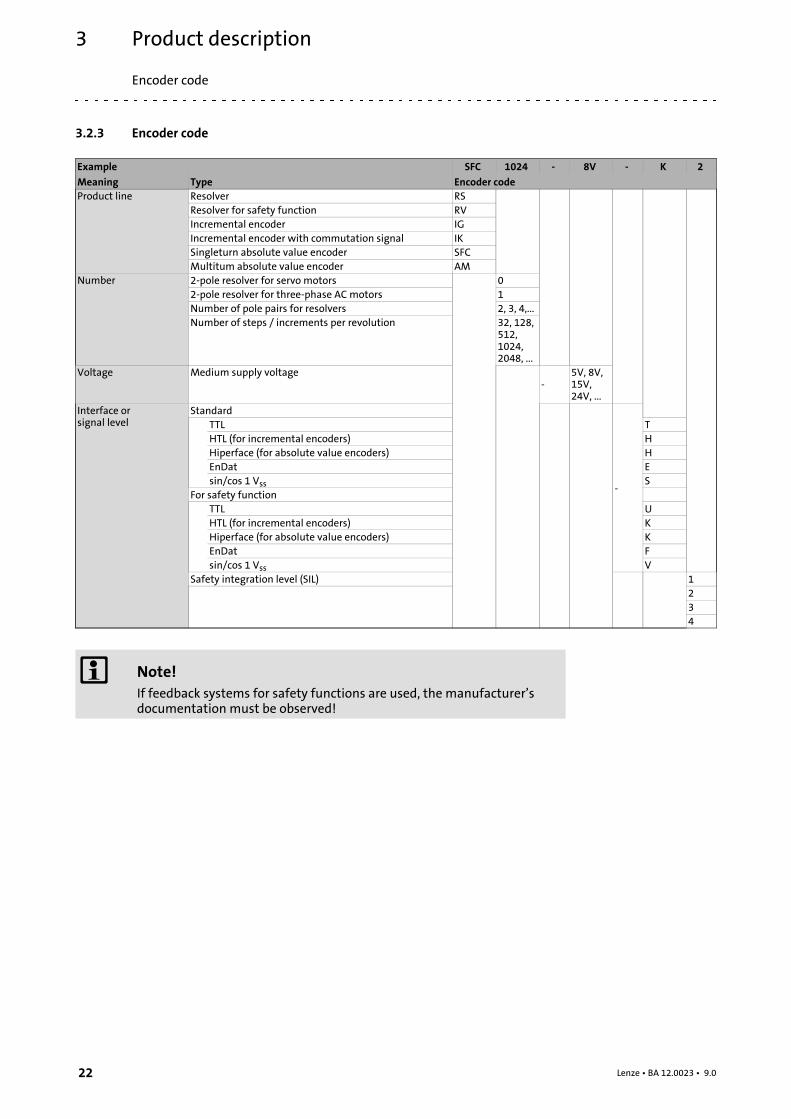
3.2.3 Encoder code
Example SFC 1024 - 8V - K 2
Meaning Type Encoder codeProduct line Resolver RS
Resolver for safety function RVIncremental encoder IGIncremental encoder with commutation signal IKSingleturn absolute value encoder SFCMultitum absolute value encoder AM
Number 2-pole resolver for servo motors 02-pole resolver for three-phase AC motors 1Number of pole pairs for resolvers 2, 3, 4,...Number of steps / increments per revolution 32, 128,
512,1024,2048, ...
Voltage Medium supply voltage-
5V, 8V,15V,24V, ...
Interface orsignal level
Standard
-
TTL THTL (for incremental encoders) HHiperface (for absolute value encoders) HEnDat Esin/cos 1 Vss S
For safety functionTTL UHTL (for incremental encoders) KHiperface (for absolute value encoders) KEnDat Fsin/cos 1 Vss V
Safety integration level (SIL) 1234
Note!If feedback systems for safety functions are used, the manufacturer’sdocumentation must be observed!
Product descriptionTransport weights
Encoder code
3
23Lenze • BA 12.0023 • 9.0
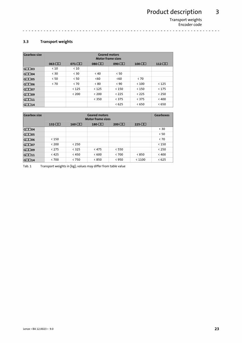
3.3 Transport weights
Gearbox size Geared motorsMotor frame sizes
063- 071- 080- 090- 100- 112-G03 < 10 < 10
G04 < 30 < 30 < 40 < 50
G05 < 50 < 50 <60 <60 < 70
G06 < 70 < 70 < 80 < 90 < 100 < 125
G07 < 125 < 125 < 150 < 150 < 175
G09 < 200 < 200 < 225 < 225 < 250
G11 < 350 < 375 < 375 < 400
G14 < 625 < 650 < 650
Gearbox size Geared motorsMotor frame sizes
Gearboxes
132- 160- 180- 200- 225-G04 < 30
G05 < 50
G06 < 150 < 70
G07 < 200 < 250 < 150
G09 < 275 < 325 < 475 < 550 < 250
G11 < 425 < 450 < 600 < 700 < 850 < 400
G14 < 700 < 750 < 850 < 950 < 1100 < 625
Tab. 1 Transport weights in [kg]; values may differ from table value
Technical dataGeneral data and operating conditions
4
24 Lenze • BA 12.0023 • 9.0
4 Technical data
4.1 General data and operating conditions
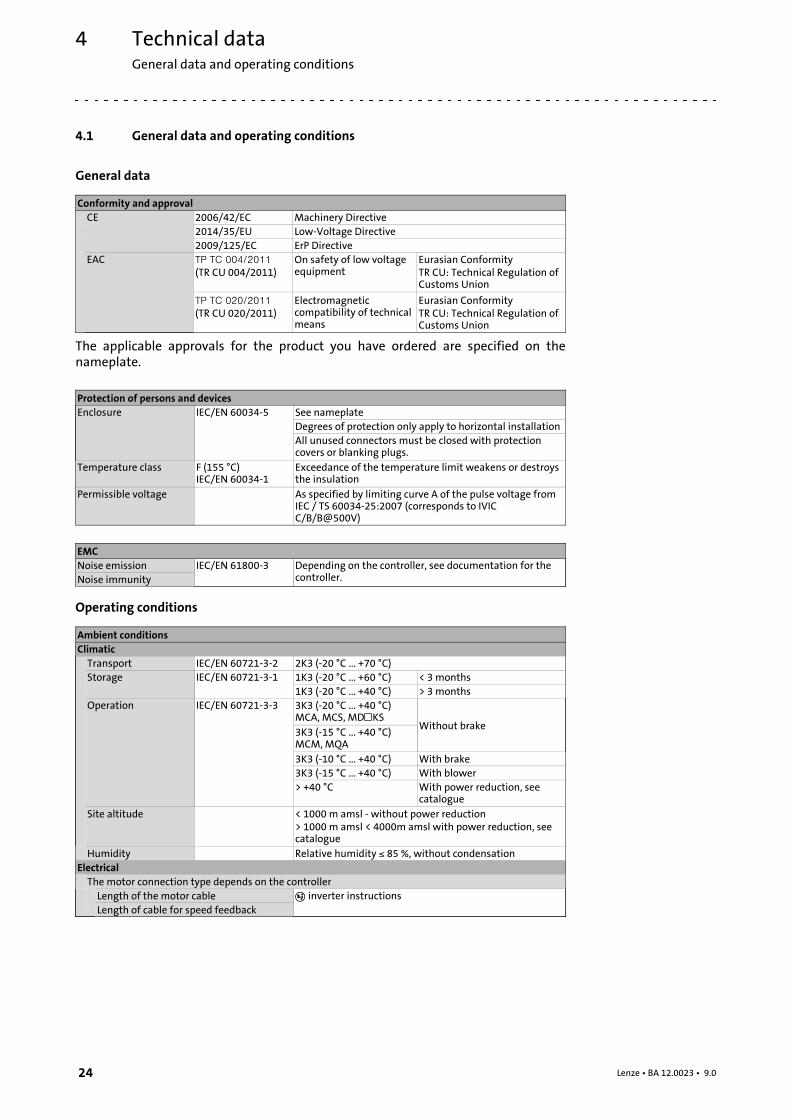
General data
Conformity and approvalCE 2006/42/EC Machinery Directive
2014/35/EU Low-Voltage Directive2009/125/EC ErP Directive
EAC
(TR CU 004/2011)On safety of low voltageequipment
Eurasian ConformityTR CU: Technical Regulation ofCustoms Union
(TR CU 020/2011)Electromagneticcompatibility of technicalmeans
Eurasian ConformityTR CU: Technical Regulation ofCustoms Union
The applicable approvals for the product you have ordered are specified on thenameplate.
Protection of persons and devicesEnclosure IEC/EN 60034-5 See nameplate
Degrees of protection only apply to horizontal installationAll unused connectors must be closed with protectioncovers or blanking plugs.
Temperature class F (155 °C)IEC/EN 60034-1
Exceedance of the temperature limit weakens or destroysthe insulation
Permissible voltage As specified by limiting curve A of the pulse voltage fromIEC / TS 60034-25:2007 (corresponds to IVICC/B/B@500V)
EMCNoise emission IEC/EN 61800-3 Depending on the controller, see documentation for the
controller.Noise immunity
Operating conditions
Ambient conditionsClimaticTransport IEC/EN 60721-3-2 2K3 (-20 °C ... +70 °C)Storage IEC/EN 60721-3-1 1K3 (-20 °C ... +60 °C) < 3 months
1K3 (-20 °C ... +40 °C) > 3 monthsOperation IEC/EN 60721-3-3 3K3 (-20 °C ... +40 °C)
MCA, MCS, MDKSWithout brake
3K3 (-15 °C ... +40 °C)MCM, MQA3K3 (-10 °C ... +40 °C) With brake3K3 (-15 °C ... +40 °C) With blower> +40 °C With power reduction, see
catalogueSite altitude < 1000 m amsl - without power reduction
> 1000 m amsl < 4000m amsl with power reduction, seecatalogue
Humidity Relative humidity 85 %, without condensationElectricalThe motor connection type depends on the controllerLength of the motor cable inverter instructionsLength of cable for speed feedback
Mechanical installationTransport equipment for gearboxes
5
25Lenze • BA 12.0023 • 9.0
5 Mechanical installation
Danger!Only transport the drive with transport equipment or hoists which aresuitable for this load ( 23). Ensure a safe fixing. Avoid shocks!
The motors attached to the gearbox are partially equipped with eyebolts.These are exclusively determined for motor/gearbox mounting anddismounting and must not be used for the complete geared motor!
5.1 Transport equipment for gearboxes
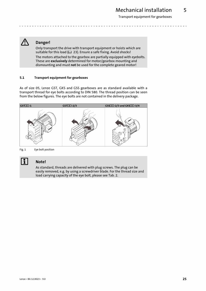
As of size 05, Lenze GST, GKS and GSS gearboxes are as standard available with atransport thread for eye bolts according to DIN 580. The thread position can be seenfrom the below figures. The eye bolts are not contained in the delivery package.
GST-1 GST-2/3 GSS-2/3 and GKS-3/4
Fig. 1 Eye bolt position
Note!As standard, threads are delivered with plug screws. The plug can beeasily removed, e.g. by using a screwdriver blade. For the thread size andload carrying capacity of the eye bolt, please see Tab. 2.
Mechanical installationTransport equipment for gearboxes
5
26 Lenze • BA 12.0023 • 9.0
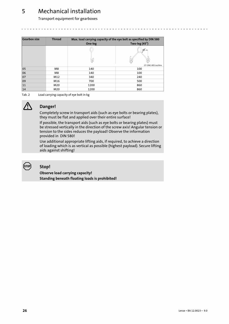
Gearbox size Thread Max. load carrying capacity of the eye bolt as specified by DIN 580One-leg Two-leg (45°)
45°
GT-GNG-005.iso/dms
05 M8 140 10006 M8 140 10007 M12 340 24009 M16 700 50011 M20 1200 86014 M20 1200 860
Tab. 2 Load carrying capacity of eye bolt in kg
Danger!Completely screw in transport aids (such as eye bolts or bearing plates),they must be flat and applied over their entire surface!
If possible, the transport aids (such as eye bolts or bearing plates) mustbe stressed vertically in the direction of the screw axis! Angular tension ortension to the sides reduces the payload! Observe the informationprovided in DIN 580!
Use additional appropriate lifting aids, if required, to achieve a directionof loading which is as vertical as possible (highest payload). Secure liftingaids against shifting!
Stop!Observe load carrying capacity!Standing beneath floating loads is prohibited!
Mechanical installationStorage
5
27Lenze • BA 12.0023 • 9.0
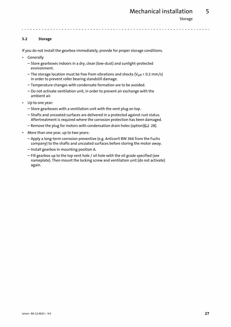
5.2 Storage
If you do not install the gearbox immediately, provide for proper storage conditions.
• Generally
– Store gearboxes indoors in a dry, clean (low-dust) and sunlight-protectedenvironment.
– The storage location must be free from vibrations and shocks (Veff < 0.2 mm/s)in order to prevent roller bearing standstill damage.
– Temperature changes with condensate formation are to be avoided.
– Do not activate ventilation unit, in order to prevent air exchange with theambient air.
• Up to one year:
– Store gearboxes with a ventilation unit with the vent plug on top.
– Shafts and uncoated surfaces are delivered in a protected against rust status.Aftertreatment is required where the corrosion protection has been damaged.
– Remove the plug for motors with condensation drain holes (option)( 28).
• More than one year, up to two years:
– Apply a long-term corrosion preventive (e.g. Anticorit BW 366 from the Fuchscompany) to the shafts and uncoated surfaces before storing the motor away.
– Install gearbox in mounting position A.
– Fill gearbox up to the top vent hole / oil hole with the oil grade specified (seenameplate). Thenmount the locking screw and ventilation unit (do not activate)again.
Mechanical installationMountingSpecification of the direction of rotation
5
28 Lenze • BA 12.0023 • 9.0
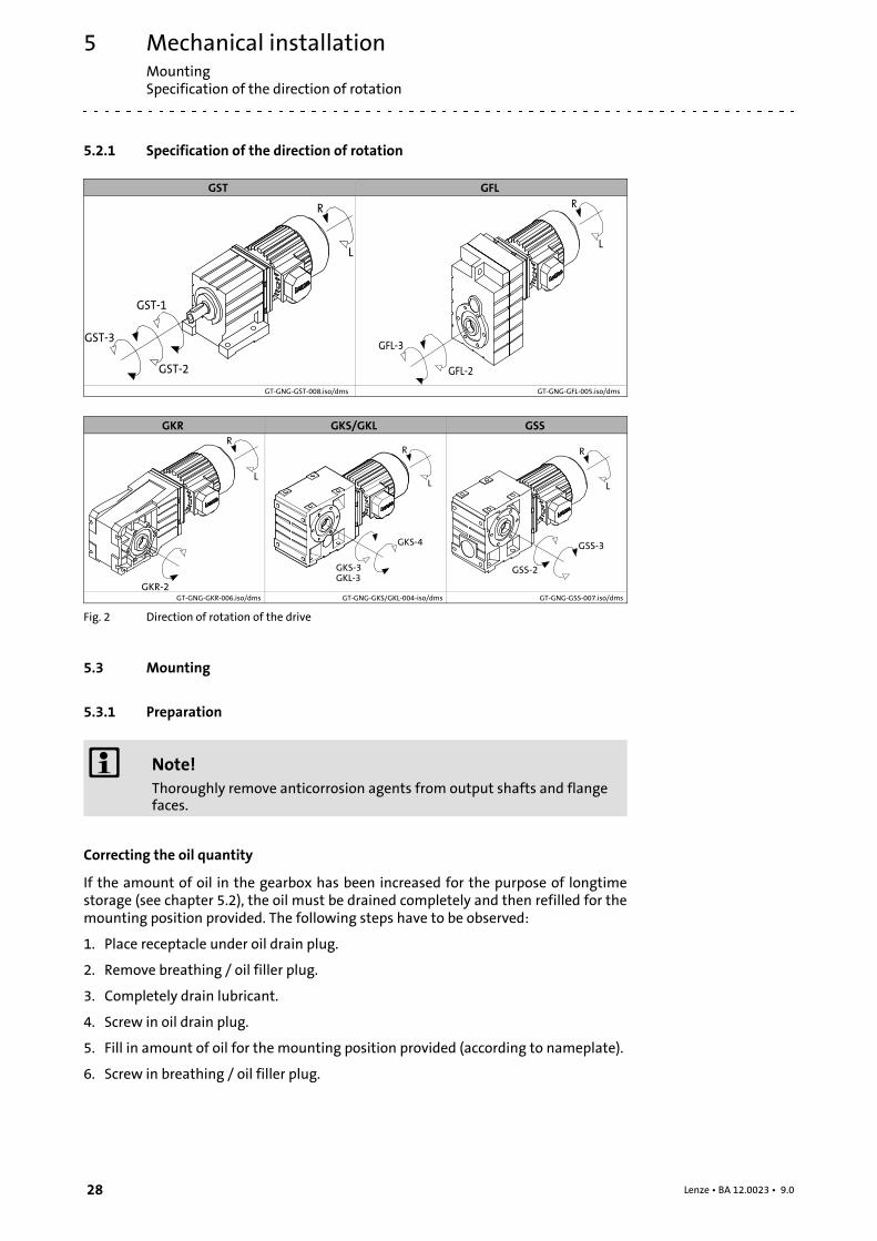
5.2.1 Specification of the direction of rotation
GST GFL
GT-GNG-GST-008.iso/dms GT-GNG-GFL-005.iso/dms
GKR GKS/GKL GSS
GT-GNG-GKR-006.iso/dms GT-GNG-GKS/GKL-004-iso/dms GT-GNG-GSS-007.iso/dms
Fig. 2 Direction of rotation of the drive
5.3 Mounting
5.3.1 Preparation
Note!Thoroughly remove anticorrosion agents from output shafts and flangefaces.
Correcting the oil quantity
If the amount of oil in the gearbox has been increased for the purpose of longtimestorage (see chapter 5.2), the oil must be drained completely and then refilled for themounting position provided. The following steps have to be observed:
1. Place receptacle under oil drain plug.
2. Remove breathing / oil filler plug.
3. Completely drain lubricant.
4. Screw in oil drain plug.
5. Fill in amount of oil for the mounting position provided (according to nameplate).
6. Screw in breathing / oil filler plug.
Mechanical installationMounting
General information about the assembly of drive systems
5
29Lenze • BA 12.0023 • 9.0
Condensation drain hole
Note!Lenze delivers motors with condensation drain holes with sealedcondensation drain holes. The holes are sealed with a plastic plug or alocking screw. This does not affect the type of protection and the motor isprotected against the ingress of foreign substances during transport andoperation. Further information, ( 57).
5.3.2 General information about the assembly of drive systems
Stop!The lubricant fill quantity of the gearboxes is matched to the mountingposition. The mounting position indicated on the nameplate must beobserved to avoid damage to the gearbox.
• Take safety measures prior to any operation:
– Disconnect the machine from the mains, ensure standstill of the drive systemand avoid any machine movement.
– Check faultless state of the drive system. Never install and commissiondamaged drive systems.
– Check drive function - machine function assignment. Check direction of( 28)rotation.
• The mounting surfaces must be plane, torsionally rigid and free from vibrations.
• Align drive system onmounting surfaces exactly with the machine shaft to bedriven.
– Be sure to carry out mounting in a manner free from distortion, in order to avoidadditional loads.
– Even out slight inaccuracies by the use of suitable flexible couplings.
• Support reaction torque by suitable measures.
• Be absolutely sure to secure fastenings of accessories and built-on accessories sothat they won’t come loose.We recommend glueing screwed connections.
5.3.3 Assembly of transmission elements on solid shafts
Draw the transmission elements onto the output shaft only by using the centeringthread.
Stop!Shocks and blows to the shafts damage the roller bearings.
Mechanical installationMountingAttachment of motors to gearboxes with bearing housing (input design N)
5
30 Lenze • BA 12.0023 • 9.0
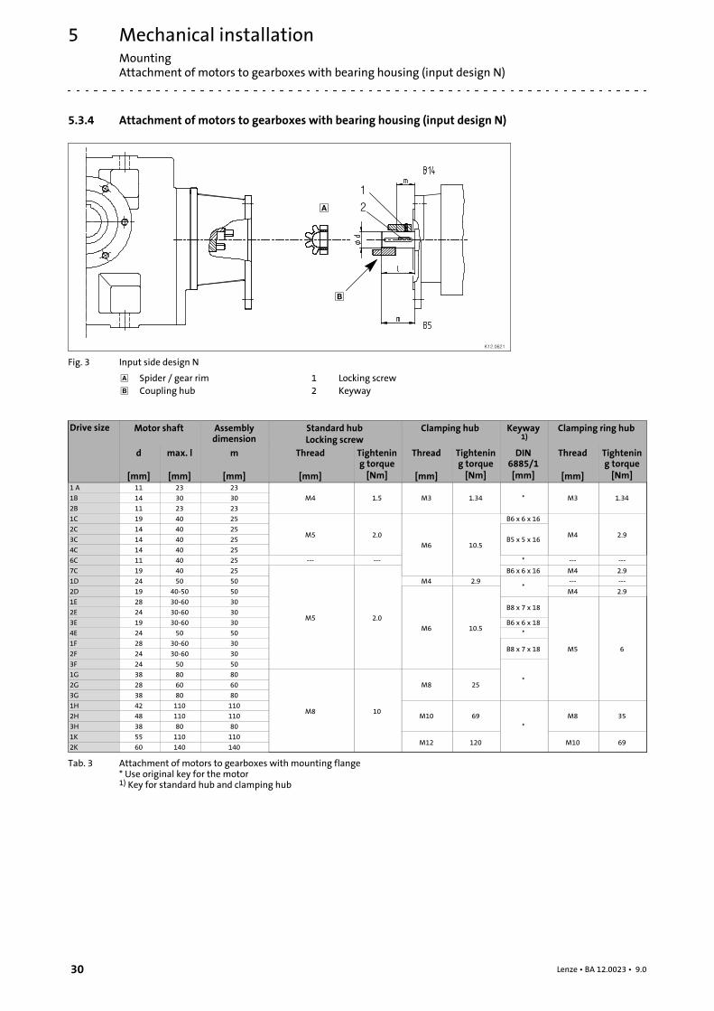
5.3.4 Attachment of motors to gearboxes with bearing housing (input design N)
12
K12.0621
Fig. 3 Input side design N
Spider / gear rim 1 Locking screw Coupling hub 2 Keyway
Drive size Motor shaft Assemblydimension
Standard hubLocking screw
Clamping hub Keyway1)
Clamping ring hub
d
[mm]
max. l
[mm]
m
[mm]
Thread
[mm]
Tightening torque[Nm]
Thread
[mm]
Tightening torque[Nm]
DIN6885/1[mm]
Thread
[mm]
Tightening torque[Nm]
1 A 11 23 23
M4 1.5 M3 1.34 * M3 1.341B 14 30 30
2B 11 23 23
1C 19 40 25
M5 2.0
M6 10.5
B6 x 6 x 16
M4 2.92C 14 40 25
B5 x 5 x 163C 14 40 25
4C 14 40 25
6C 11 40 25 --- --- * --- ---
7C 19 40 25
M5 2.0
B6 x 6 x 16 M4 2.9
1D 24 50 50 M4 2.9*
--- ---
2D 19 40-50 50
M6 10.5
M4 2.9
1E 28 30-60 30B8 x 7 x 18
M5 6
2E 24 30-60 30
3E 19 30-60 30 B6 x 6 x 18
4E 24 50 50 *
1F 28 30-60 30B8 x 7 x 18
2F 24 30-60 30
3F 24 50 50
*1G 38 80 80
M8 10
M8 252G 28 60 60
3G 38 80 80
1H 42 110 110
M10 69
*
M8 352H 48 110 110
3H 38 80 80
1K 55 110 110M12 120 M10 69
2K 60 140 140
Tab. 3 Attachment of motors to gearboxes with mounting flange* Use original key for the motor1) Key for standard hub and clamping hub
Mechanical installationMounting
Coupling hubs
5
31Lenze • BA 12.0023 • 9.0
5.3.5 Coupling hubs
General
Note!Standard hubs, clamping hubs and clamping ring hubs aremaintenance-free.We recommend checking the star-shaped spider andsystem components when inspecting the drive.
5.3.5.1 Assembly of standard hub / clamping hub
1. Fit motor key (2).
– Fit enclosed key for drive sizesC,E,F.2. Push the coupling hub over the motor shaft, mounting dimension m (see Fig. 3
and Tab. 3) must be observed.
3. Secure coupling hub against axial movement using the fixing screw or clampingscrew (1).
4. Lay spider in the coupling claw on the gearbox side.
5. Align claws of the motor-side coupling hub with its counterpart.
6. Slowly push on motor, and bolt on to the gearbox flange.
Mechanical installationMountingCoupling hubs
5
32 Lenze • BA 12.0023 • 9.0
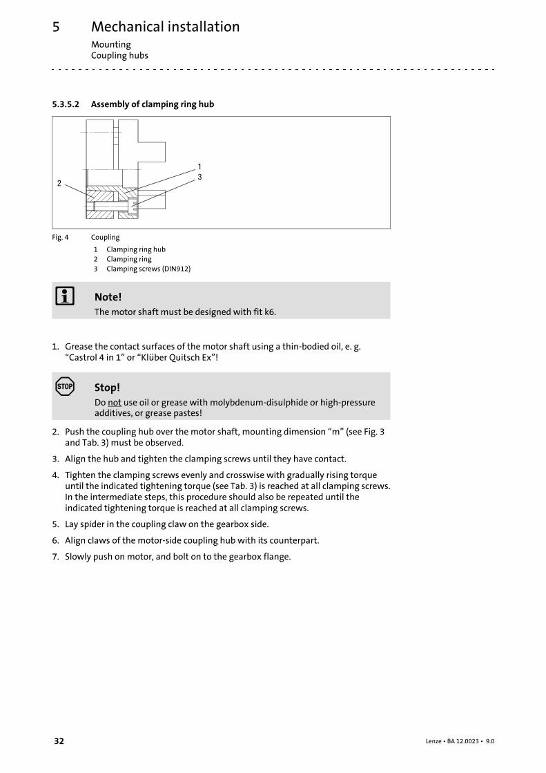
5.3.5.2 Assembly of clamping ring hub
1
23
Fig. 4 Coupling
1 Clamping ring hub2 Clamping ring3 Clamping screws (DIN912)
Note!The motor shaft must be designed with fit k6.
1. Grease the contact surfaces of the motor shaft using a thin-bodied oil, e. g.“Castrol 4 in 1” or “Klüber Quitsch Ex”!
Stop!Do not use oil or grease with molybdenum-disulphide or high-pressureadditives, or grease pastes!
2. Push the coupling hub over the motor shaft, mounting dimension “m” (see Fig. 3and Tab. 3) must be observed.
3. Align the hub and tighten the clamping screws until they have contact.
4. Tighten the clamping screws evenly and crosswise with gradually rising torqueuntil the indicated tightening torque (see Tab. 3) is reached at all clamping screws.In the intermediate steps, this procedure should also be repeated until theindicated tightening torque is reached at all clamping screws.
5. Lay spider in the coupling claw on the gearbox side.
6. Align claws of the motor-side coupling hub with its counterpart.
7. Slowly push on motor, and bolt on to the gearbox flange.
Mechanical installationMounting
Attachment of gearboxes with hollow shafts and keyway
5
33Lenze • BA 12.0023 • 9.0
5.3.5.3 Disassembly of clamping ring hub
1. Loosen the clamping screws evenly one after the other.
Stop!Each screwmust only be loosened by half a revolution per pass! Unscrewall clamping screws by 3 - 4 threads.
2. Remove the screws next to the forcing threads and screw them into the otherthreads until they have contact.
3. Tighten the screws in the forcing threads crosswise and step-by-step so that theclamping ring is loosened.
4. Clean and grease all contact surfaces including threads and head of the clampingscrews before reassembly.
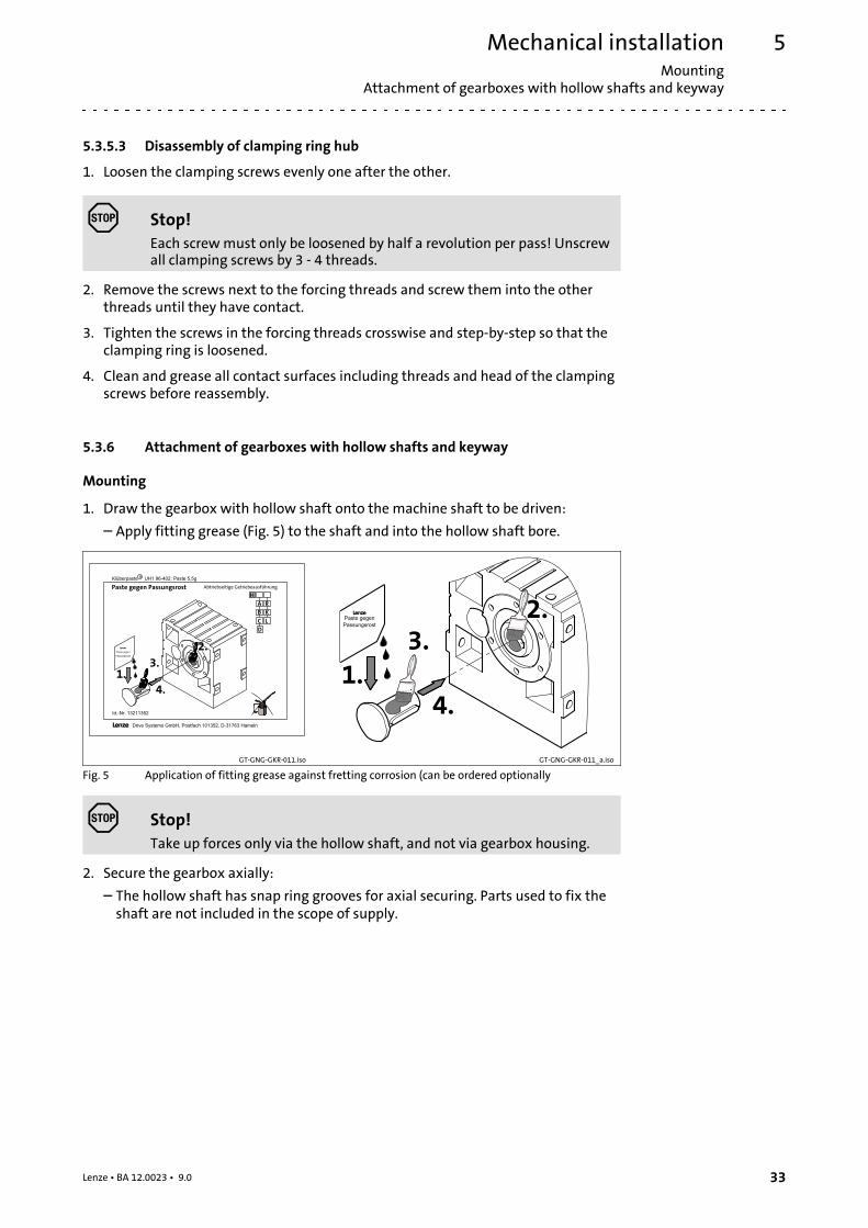
5.3.6 Attachment of gearboxes with hollow shafts and keyway
Mounting
1. Draw the gearbox with hollow shaft onto the machine shaft to be driven:
– Apply fitting grease (Fig. 5) to the shaft and into the hollow shaft bore.
GT-GNG-GKR-011.iso GT-GNG-GKR-011_a.iso
Fig. 5 Application of fitting grease against fretting corrosion (can be ordered optionally
Stop!Take up forces only via the hollow shaft, and not via gearbox housing.
2. Secure the gearbox axially:
– The hollow shaft has snap ring grooves for axial securing. Parts used to fix theshaft are not included in the scope of supply.
Mechanical installationMountingAttachment of gearboxes with hollow shafts and keyway
5
34 Lenze • BA 12.0023 • 9.0
K12.0611
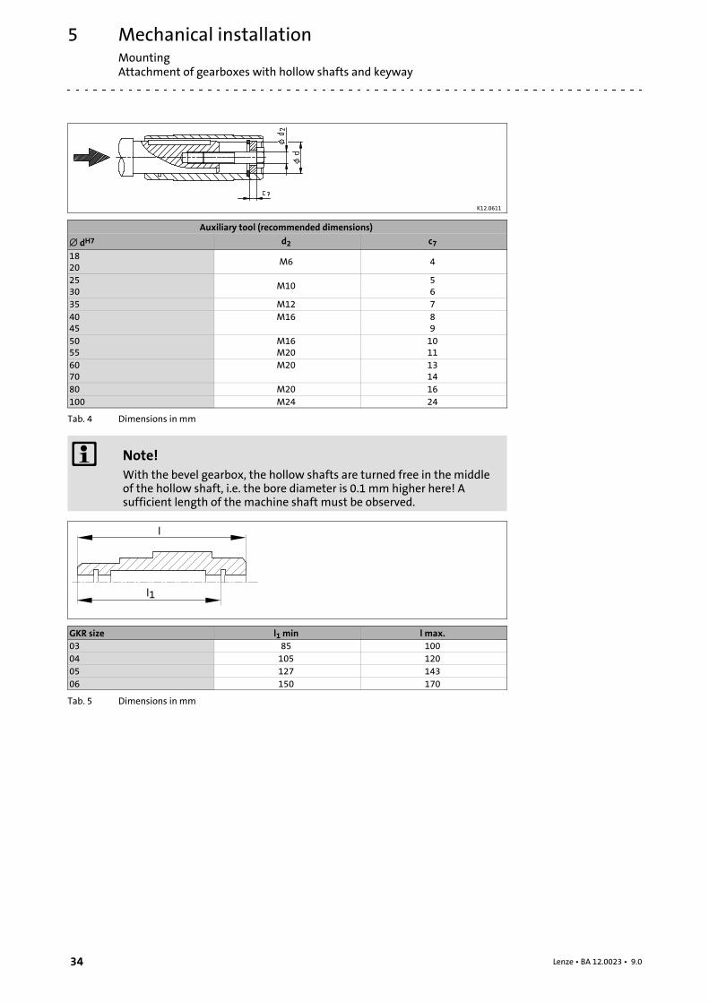
Auxiliary tool (recommended dimensions)
dH7 d2 c71820
M6 4
2530
M1056
35 M12 74045
M16 89
5055
M16M20
1011
6070
M20 1314
80 M20 16100 M24 24
Tab. 4 Dimensions in mm
Note!With the bevel gearbox, the hollow shafts are turned free in the middleof the hollow shaft, i.e. the bore diameter is 0.1 mm higher here! Asufficient length of the machine shaft must be observed.
GKR size l1 min l max.03 85 10004 105 12005 127 14306 150 170
Tab. 5 Dimensions in mm
Mechanical installationMounting
Mounting the shrink disc with a rotating cover
5
35Lenze • BA 12.0023 • 9.0
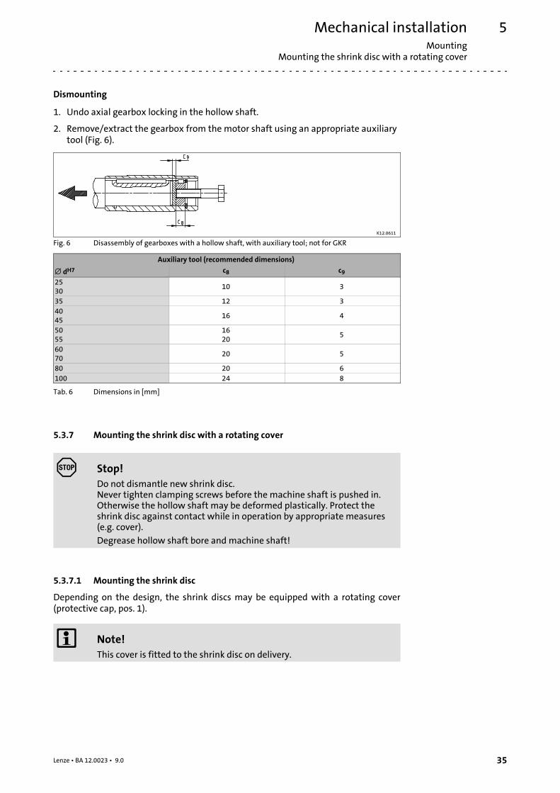
Dismounting
1. Undo axial gearbox locking in the hollow shaft.
2. Remove/extract the gearbox from the motor shaft using an appropriate auxiliarytool (Fig. 6).
K12.0611
Fig. 6 Disassembly of gearboxes with a hollow shaft, with auxiliary tool; not for GKR
Auxiliary tool (recommended dimensions)
dH7 c8 c92530
10 3
35 12 34045
16 4
5055
1620
5
6070
20 5
80 20 6100 24 8
Tab. 6 Dimensions in [mm]
5.3.7 Mounting the shrink disc with a rotating cover
Stop!Do not dismantle new shrink disc.Never tighten clamping screws before the machine shaft is pushed in.Otherwise the hollow shaft may be deformed plastically. Protect theshrink disc against contact while in operation by appropriate measures(e.g. cover).
Degrease hollow shaft bore and machine shaft!
5.3.7.1 Mounting the shrink disc
Depending on the design, the shrink discs may be equipped with a rotating cover(protective cap, pos. 1).
Note!This cover is fitted to the shrink disc on delivery.
Mechanical installationMountingMounting the shrink disc
5
36 Lenze • BA 12.0023 • 9.0
1.
5.
1
1 2
2
KL_GFL06_001-dms
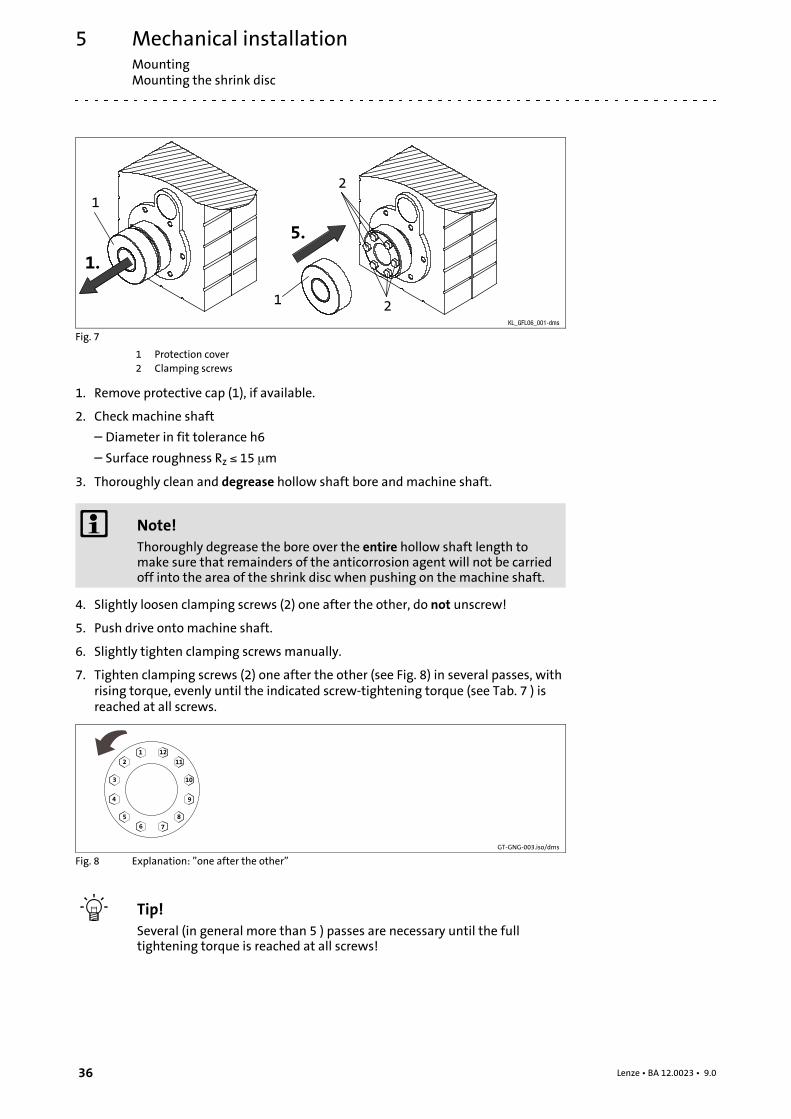
Fig. 7
1 Protection cover2 Clamping screws
1. Remove protective cap (1), if available.
2. Check machine shaft
– Diameter in fit tolerance h6
– Surface roughness Rz 15 m
3. Thoroughly clean and degrease hollow shaft bore and machine shaft.
Note!Thoroughly degrease the bore over the entire hollow shaft length tomake sure that remainders of the anticorrosion agent will not be carriedoff into the area of the shrink disc when pushing on the machine shaft.
4. Slightly loosen clamping screws (2) one after the other, do not unscrew!
5. Push drive onto machine shaft.
6. Slightly tighten clamping screws manually.
7. Tighten clamping screws (2) one after the other (see Fig. 8) in several passes, withrising torque, evenly until the indicated screw-tightening torque (see Tab. 7 ) isreached at all screws.
GT-GNG-003.iso/dms
Fig. 8 Explanation: ”one after the other”
Tip!Several (in general more than 5 ) passes are necessary until the fulltightening torque is reached at all screws!
Mechanical installationMounting
Mounting the shrink disc
5
37Lenze • BA 12.0023 • 9.0
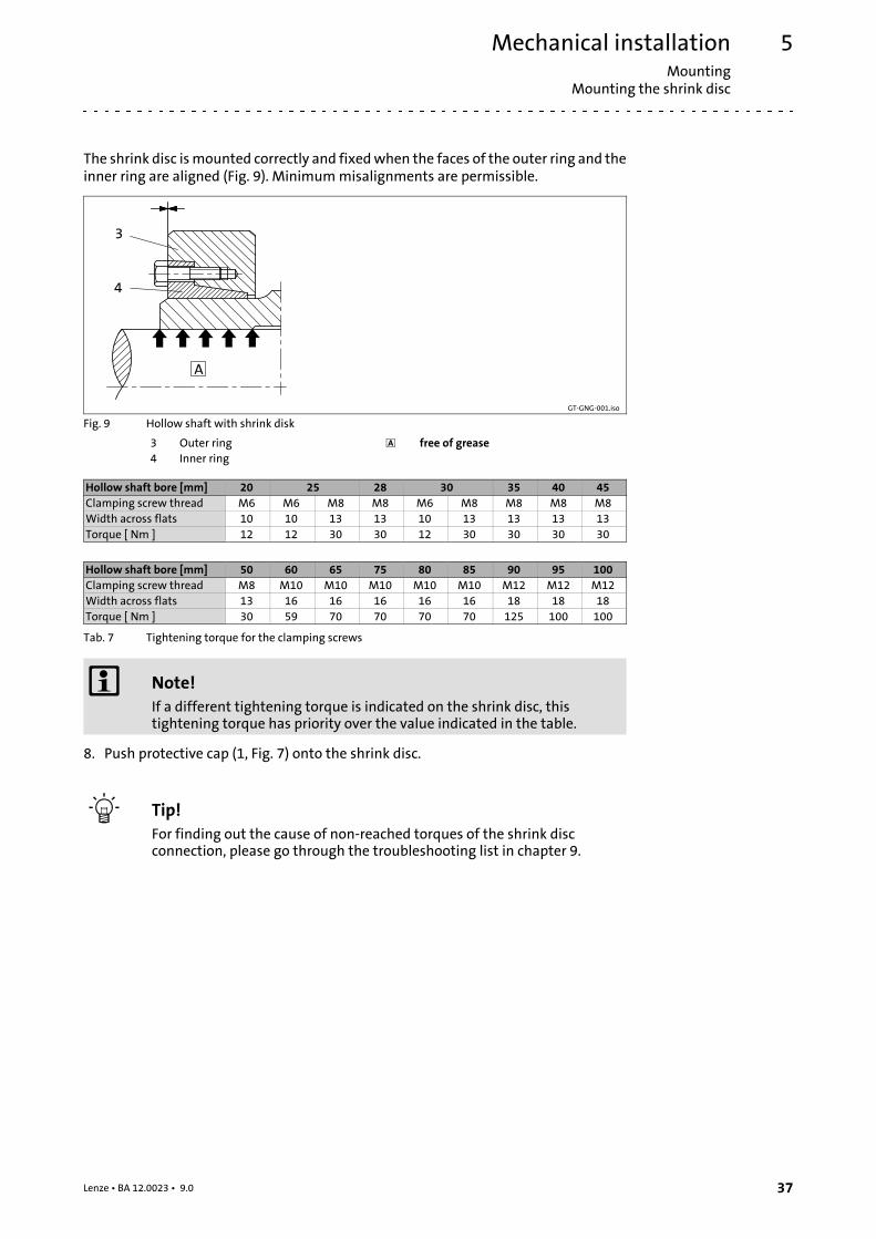
The shrink disc ismounted correctly and fixedwhen the faces of the outer ring and theinner ring are aligned (Fig. 9). Minimummisalignments are permissible.
GT-GNG-001.iso
Fig. 9 Hollow shaft with shrink disk
3 Outer ring free of grease4 Inner ring
Hollow shaft bore [mm] 20 25 28 30 35 40 45Clamping screw thread M6 M6 M8 M8 M6 M8 M8 M8 M8Width across flats 10 10 13 13 10 13 13 13 13Torque [ Nm ] 12 12 30 30 12 30 30 30 30
Hollow shaft bore [mm] 50 60 65 75 80 85 90 95 100Clamping screw thread M8 M10 M10 M10 M10 M10 M12 M12 M12Width across flats 13 16 16 16 16 16 18 18 18Torque [ Nm ] 30 59 70 70 70 70 125 100 100
Tab. 7 Tightening torque for the clamping screws
Note!If a different tightening torque is indicated on the shrink disc, thistightening torque has priority over the value indicated in the table.
8. Push protective cap (1, Fig. 7) onto the shrink disc.
Tip!For finding out the cause of non-reached torques of the shrink discconnection, please go through the troubleshooting list in chapter 9.
Mechanical installationMountingMounting the shrink disc
5
38 Lenze • BA 12.0023 • 9.0
Dismounting
Danger!Loose drive components or drive components falling downmay causeinjury to persons or damage to the machine. Secure the drivecomponents before disassembly.
1. Remove protective cap (1).
2. Loosen clamping screws (2) evenly one after the other each by ¼ revolution inseveral passes. Do not unscrew clamping screws completely to prevent accidents!
3. Press off outer ring (see Fig. 9), if necessary. For this, loosen the outer ring usingthe forcing threads and some clamping screws (number corresponding to theforcing threads in the inner ring). For loosening the outer ring, screw in the screwsevenly to prevent canting. Press off the outer ring until loosened completely.
4. Remove the drive from the machine shaft.
Stop!Dismantle the shrink disc only for cleaning purposes. Afterwards, greasebevel surfaces and screws using a solid lubricant with a friction factor of = 0.04.
• Suitable lubricants on molybdenum-disulphide lubricant (MoS2) basis are, e.g.:
– Molykote G Rapid (company Dow Corning)
– Molykote BR2 Plus (company Dow Corning)
– Molykombin UMFT1 (company Klüber Lubrication)
Usually, disassembly problems only occur if:
• the connection is spinning due to overload or a too low friction factor and frettingcorrosion has occurred,
• the shrink disc has been tightened too much leading to a plastic deformation ofcomponents,
• the components are corroded.
Mechanical installationMounting
Mounting the fixed cover
5
39Lenze • BA 12.0023 • 9.0
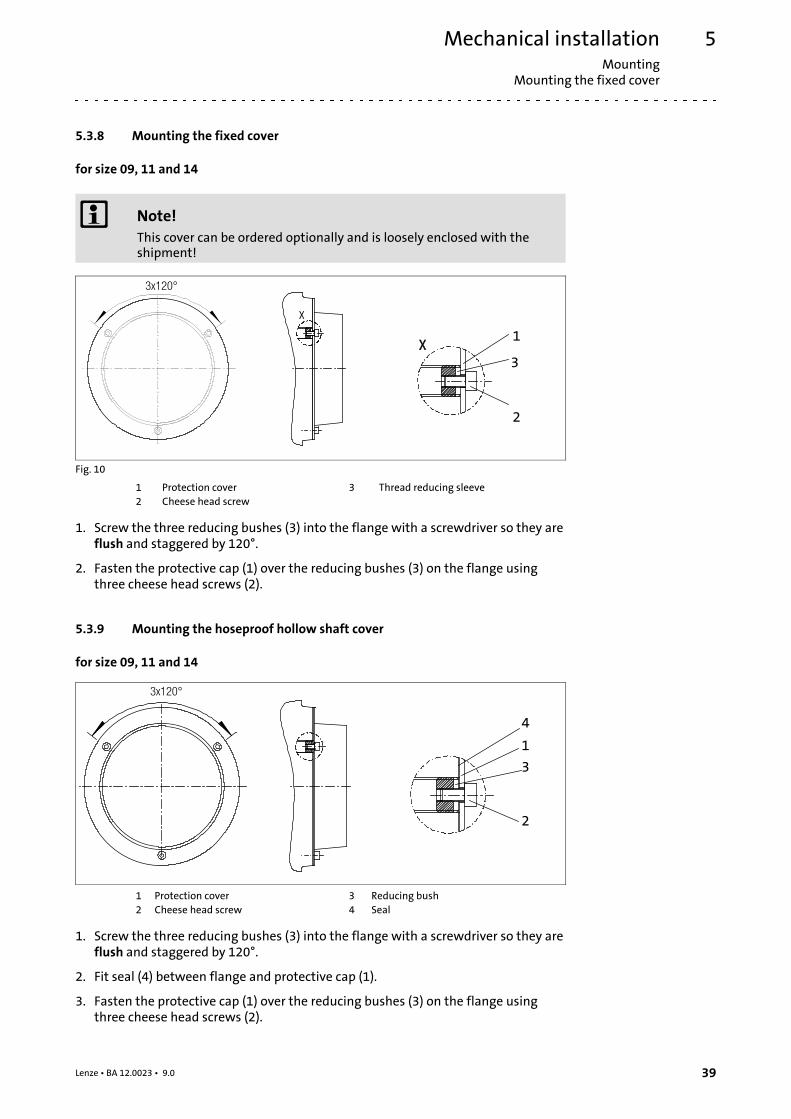
5.3.8 Mounting the fixed cover
for size 09, 11 and 14
Note!This cover can be ordered optionally and is loosely enclosed with theshipment!
2
x
x
3x120°
1
3
Fig. 10
1 Protection cover 3 Thread reducing sleeve2 Cheese head screw
1. Screw the three reducing bushes (3) into the flange with a screwdriver so they areflush and staggered by 120°.
2. Fasten the protective cap (1) over the reducing bushes (3) on the flange usingthree cheese head screws (2).
5.3.9 Mounting the hoseproof hollow shaft cover
for size 09, 11 and 14
1
3
2
4
3x120°
1 Protection cover 3 Reducing bush2 Cheese head screw 4 Seal
1. Screw the three reducing bushes (3) into the flange with a screwdriver so they areflush and staggered by 120°.
2. Fit seal (4) between flange and protective cap (1).
3. Fasten the protective cap (1) over the reducing bushes (3) on the flange usingthree cheese head screws (2).
Mechanical installationMountingGearboxes with breathers
5
40 Lenze • BA 12.0023 • 9.0
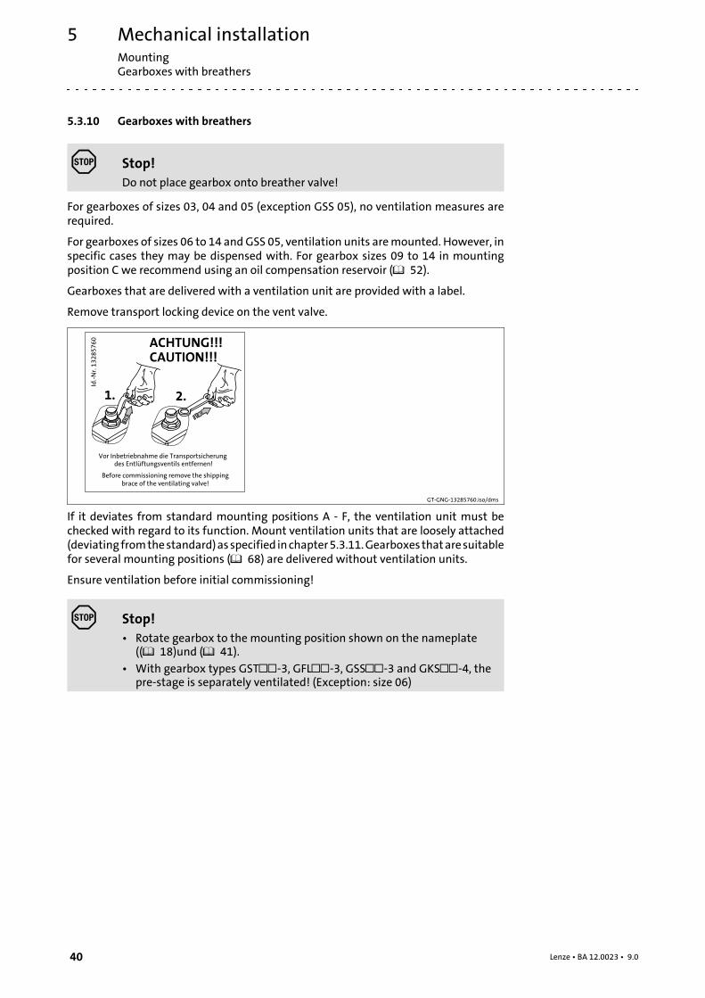
5.3.10 Gearboxes with breathers
Stop!Do not place gearbox onto breather valve!
For gearboxes of sizes 03, 04 and 05 (exception GSS 05), no ventilation measures arerequired.
For gearboxes of sizes 06 to 14 andGSS 05, ventilation units aremounted. However, inspecific cases they may be dispensed with. For gearbox sizes 09 to 14 in mountingposition C we recommend using an oil compensation reservoir ( 52).
Gearboxes that are delivered with a ventilation unit are provided with a label.
Remove transport locking device on the vent valve.
GT-GNG-13285760.iso/dms
If it deviates from standard mounting positions A - F, the ventilation unit must bechecked with regard to its function. Mount ventilation units that are loosely attached(deviatingfromthestandard)asspecified inchapter5.3.11.Gearboxesthataresuitablefor several mounting positions ( 68) are delivered without ventilation units.
Ensure ventilation before initial commissioning!
Stop!• Rotate gearbox to the mounting position shown on the nameplate
(( 18)und ( 41).
• With gearbox types GST-3, GFL-3, GSS-3 and GKS-4, thepre-stage is separately ventilated! (Exception: size 06)

Mechanical installationMounting
Breather position, oil filling screw and drain plug
5
41Lenze • BA 12.0023 • 9.0
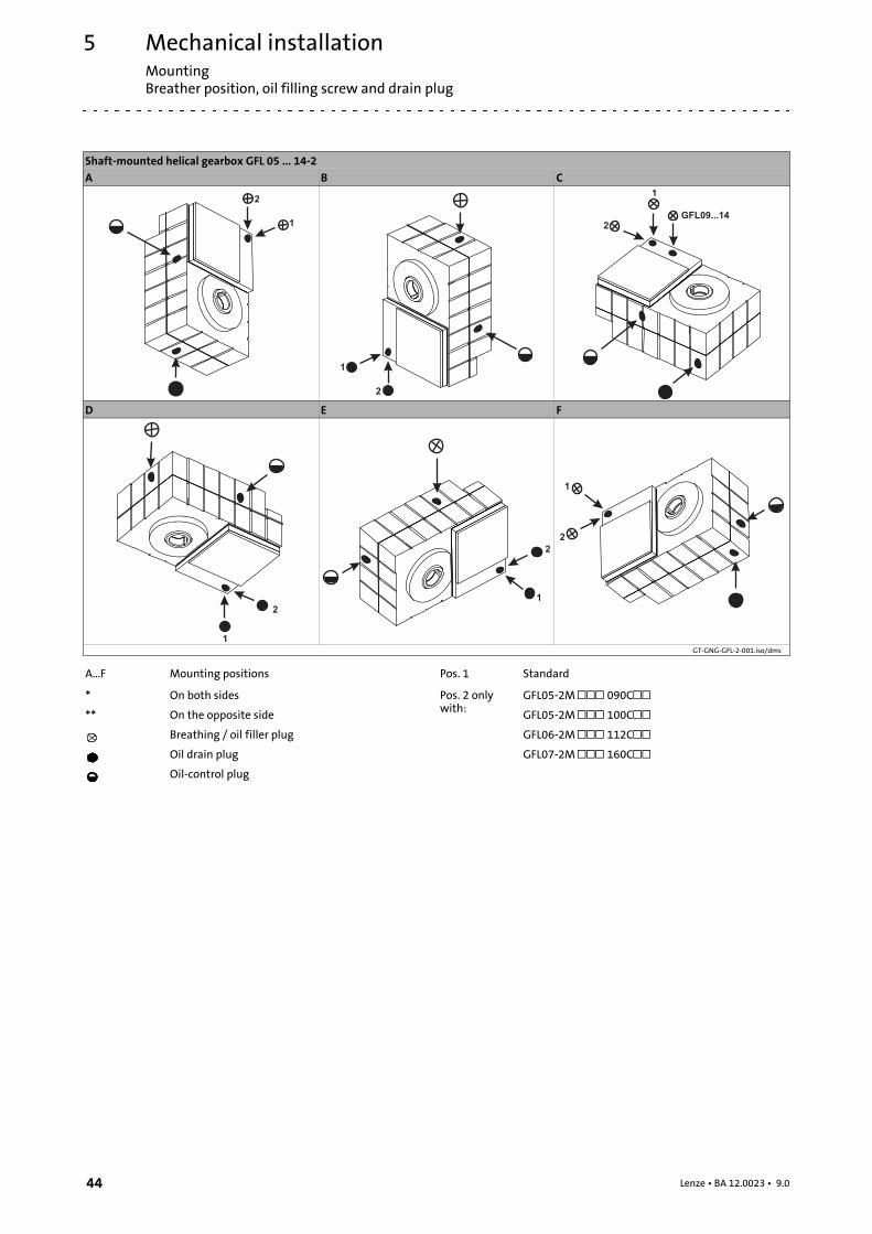
5.3.11 Breather position, oil filling screw and drain plug
Helical gearbox GST 05 ... 09-1A B
C D
E F
GT-GNG-GST-1-001_A-F.iso/dms
A...F Mounting positions Oil drain plug
* On both sides Oil-control plug
** On the opposite side Pos. 1 Standard
Breathing / oil filler plug Pos. 2 onlywith:
GST05-1A 080C22
Mechanical installationMountingBreather position, oil filling screw and drain plug
5
42 Lenze • BA 12.0023 • 9.0
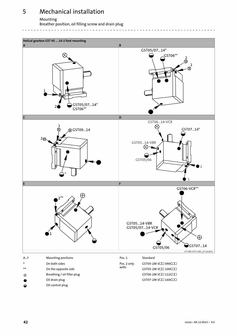
Helical gearbox GST 05 ... 14-2 foot mountingA B
C D
E F
GT-GNG-GST-2-001_A-F.iso/dms
A...F Mounting positions Pos. 1 Standard
* On both sides Pos. 2 onlywith:
GST05-2M V 090C** On the opposite side GST05-2M V 100C
Breathing / oil filler plug GST06-2M V 112COil drain plug GST07-2M V 160COil-control plug
Mechanical installationMounting
Breather position, oil filling screw and drain plug
5
43Lenze • BA 12.0023 • 9.0
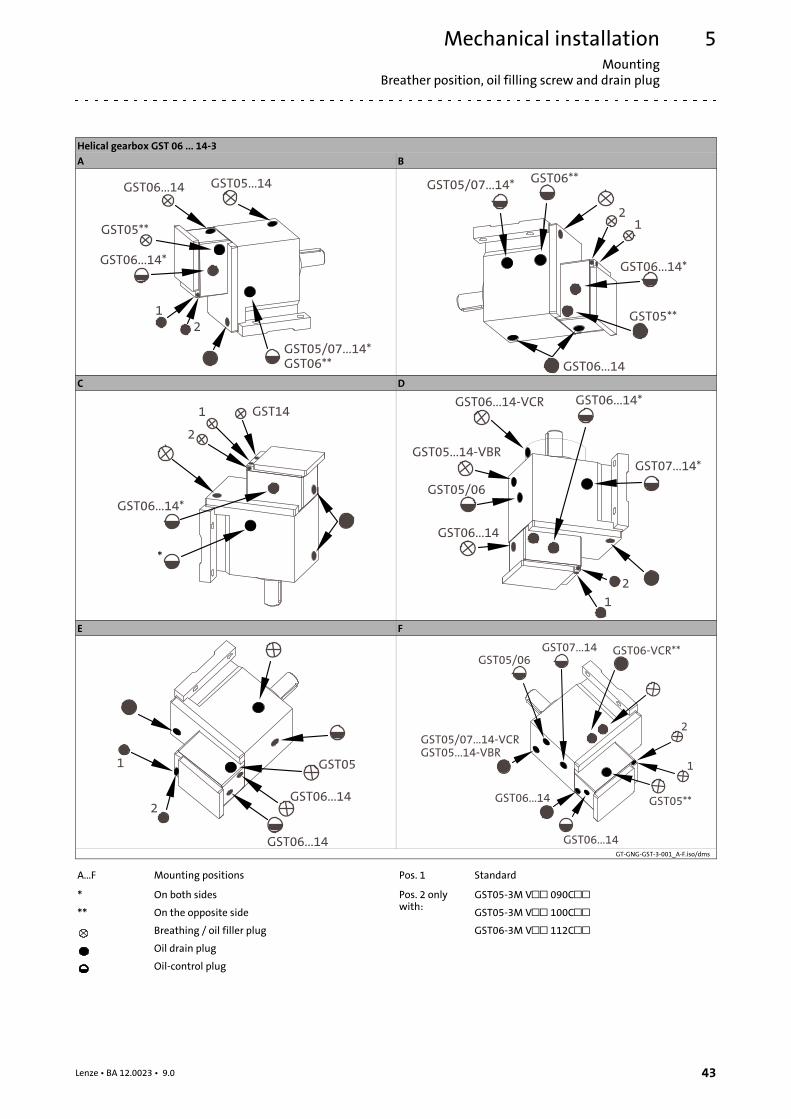
Helical gearbox GST 06 ... 14-3A B
C D
E F
GT-GNG-GST-3-001_A-F.iso/dms
A...F Mounting positions Pos. 1 Standard
* On both sides Pos. 2 onlywith:
GST05-3M V 090C** On the opposite side GST05-3M V 100C
Breathing / oil filler plug GST06-3M V 112COil drain plug
Oil-control plug
Mechanical installationMountingBreather position, oil filling screw and drain plug
5
44 Lenze • BA 12.0023 • 9.0
Shaft-mounted helical gearbox GFL 05 ... 14-2A B C
2
1
1
2
GFL09...14
1
2
D E F
1
2
1
2
1
2
GT-GNG-GFL-2-001.iso/dms
A...F Mounting positions Pos. 1 Standard
* On both sides Pos. 2 onlywith:
GFL05-2M 090C** On the opposite side GFL05-2M 100C
Breathing / oil filler plug GFL06-2M 112COil drain plug GFL07-2M 160COil-control plug
Mechanical installationMounting
Breather position, oil filling screw and drain plug
5
45Lenze • BA 12.0023 • 9.0
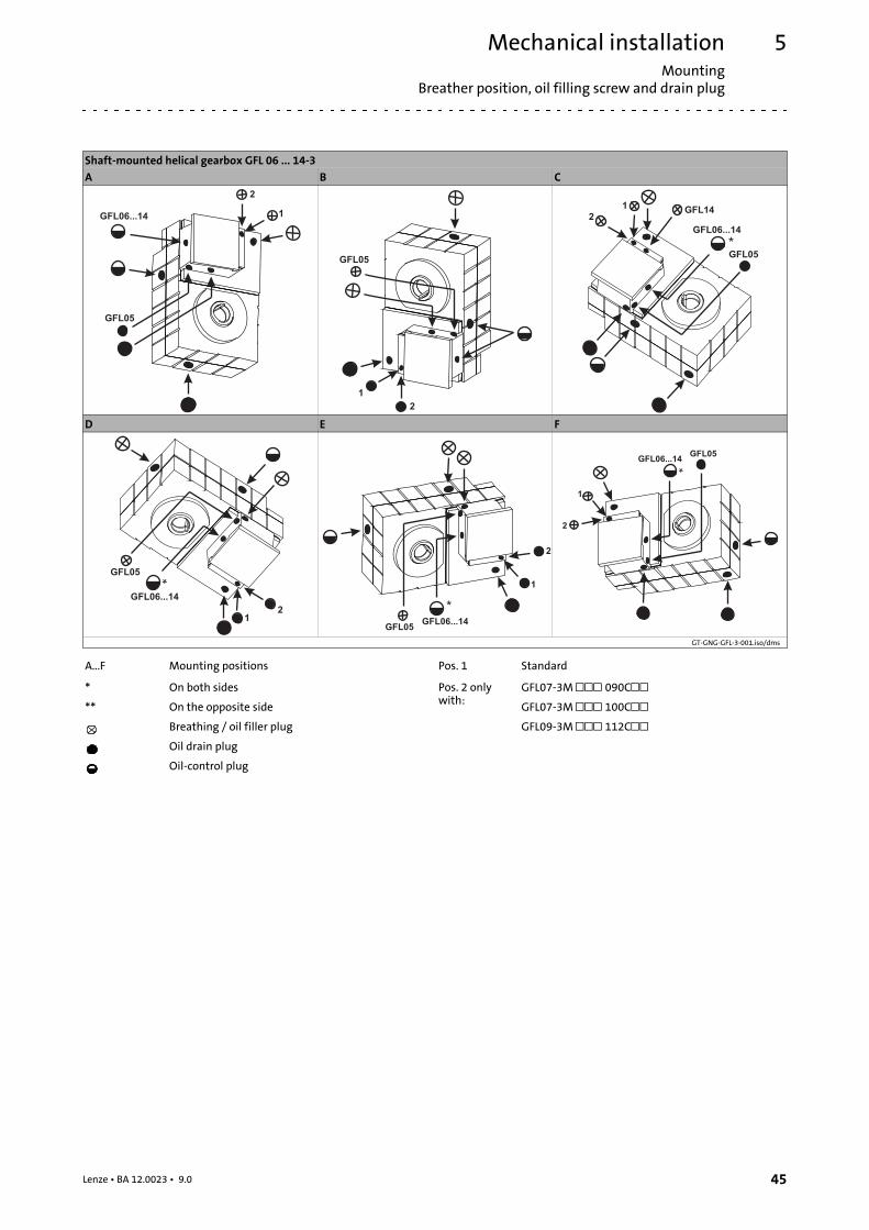
Shaft-mounted helical gearbox GFL 06 ... 14-3A B C
2
1
GFL05
GFL06...14
1
2
GFL05
1
2
*
GFL14
GFL05
GFL06...14
D E F
12
*GFL05
GFL06...14
*
1
2
GFL05GFL06...14
*
1
2
GFL05GFL06...14
GT-GNG-GFL-3-001.iso/dms
A...F Mounting positions Pos. 1 Standard
* On both sides Pos. 2 onlywith:
GFL07-3M 090C** On the opposite side GFL07-3M 100C
Breathing / oil filler plug GFL09-3M 112COil drain plug
Oil-control plug
Mechanical installationMountingBreather position, oil filling screw and drain plug
5
46 Lenze • BA 12.0023 • 9.0
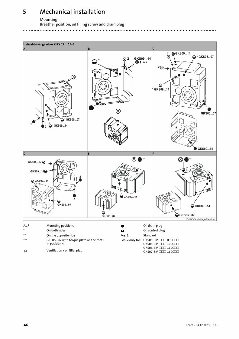
Helical-bevel gearbox GKS 05 ... 14-3A B C
1
2
* GKS05...07
* GKS09...14
1
2*
GKS09...14
***
GKS09...141
2
* GKS05...07
* GKS09...14
GKS09...14
GKS05...07
D E F
GKS09...14
1
2
GKS09...14
GKS05...07
GKS05...07
GKS05...07
GKS09...14
**
GKS09...14
GKS05...07
**
GT-GNG-GKS-3-001_A-F.iso/dms
A...F Mounting positions Oil drain plug
* On both sides Oil control plug
** On the opposite side Pos. 1 Standard
*** GKS05...07 with torque plate on the footin position 4
Pos. 2 only for: GKS05-3M 090CGKS05-3M 100CGKS06-3M 112CGKS07-3M 160CVentilation / oil filler plug
Mechanical installationMounting
Breather position, oil filling screw and drain plug
5
47Lenze • BA 12.0023 • 9.0
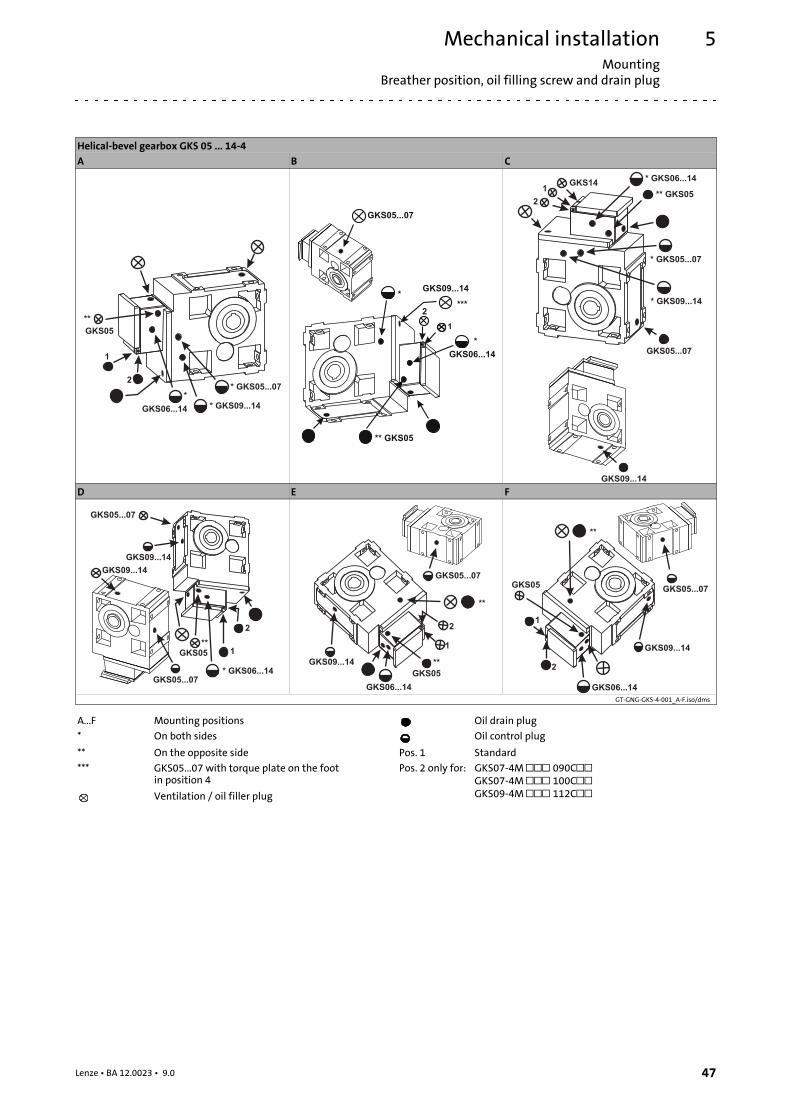
Helical-bevel gearbox GKS 05 ... 14-4A B C
1
2* GKS05...07
*
* GKS09...14
GKS05
**
GKS06...14
GKS05...07
2
*
GKS06...14
GKS09...14
1
***
*
** GKS05
GKS141
2
* GKS05...07
* GKS09...14
* GKS06...14
GKS05...07
GKS09...14
** GKS05
D E F
GKS09...14
GKS09...14
GKS05...07
* GKS06...14
GKS05...07
1
2
GKS05
**
GKS09...14
1
2
GKS05...07
**
GKS06...14
**
GKS05
GKS05...07
1
2
GKS09...14
**
GKS06...14
GKS05
GT-GNG-GKS-4-001_A-F.iso/dms
A...F Mounting positions Oil drain plug
* On both sides Oil control plug
** On the opposite side Pos. 1 Standard
*** GKS05...07 with torque plate on the footin position 4
Pos. 2 only for: GKS07-4M 090CGKS07-4M 100CGKS09-4M 112CVentilation / oil filler plug
Mechanical installationMountingBreather position, oil filling screw and drain plug
5
48 Lenze • BA 12.0023 • 9.0
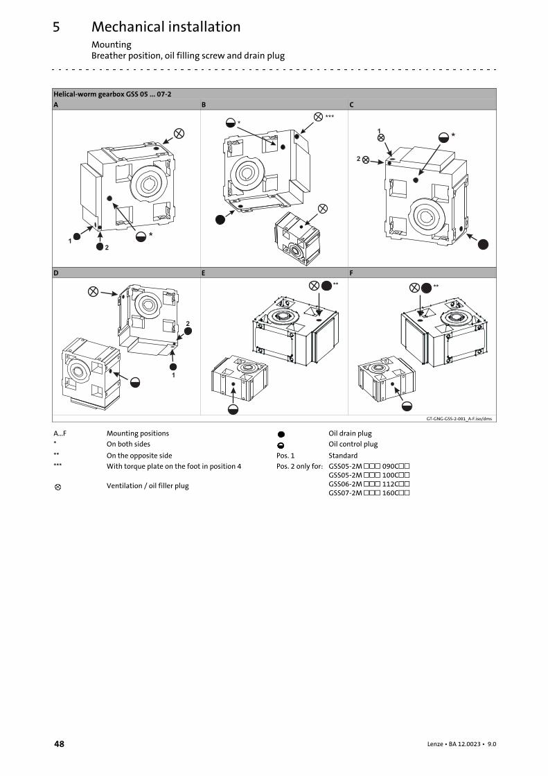
Helical-worm gearbox GSS 05 ... 07-2A B C
1
2
*
*
***
1
2
*
D E F
1
2
** **
GT-GNG-GSS-2-001_A-F.iso/dms
A...F Mounting positions Oil drain plug
* On both sides Oil control plug
** On the opposite side Pos. 1 Standard
*** With torque plate on the foot in position 4 Pos. 2 only for: GSS05-2M 090CGSS05-2M 100CGSS06-2M 112CGSS07-2M 160C
Ventilation / oil filler plug
Mechanical installationMounting
Breather position, oil filling screw and drain plug
5
49Lenze • BA 12.0023 • 9.0
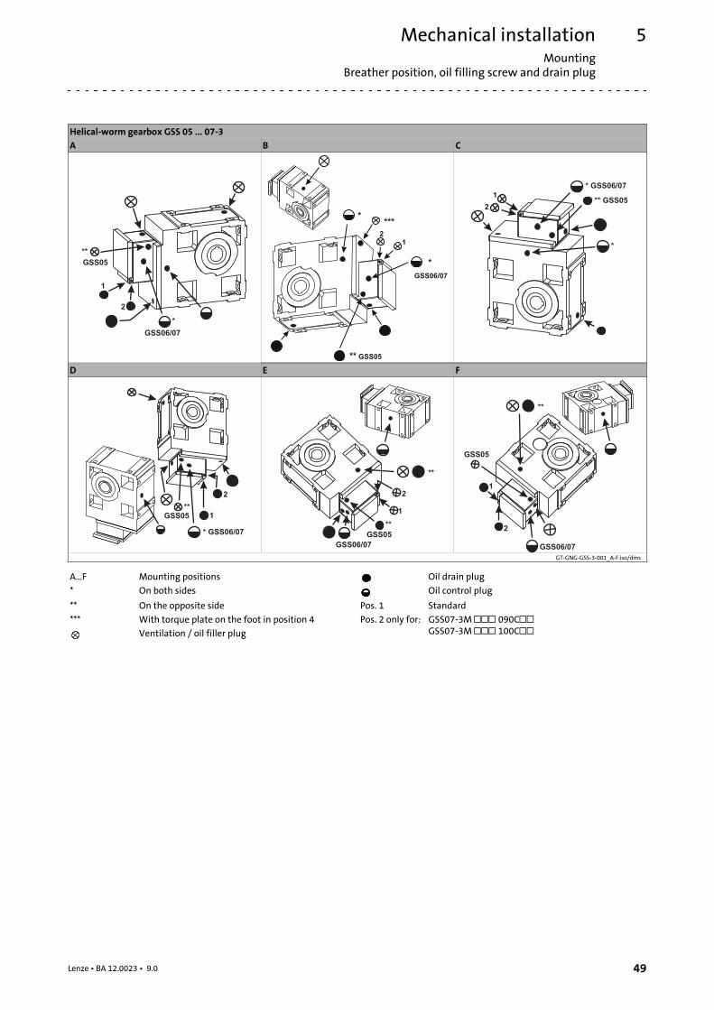
Helical-worm gearbox GSS 05 ... 07-3A B C
1
2
*
GSS06/07
GSS05
**
2
1
GSS06/07
*
*
** GSS05
***
1
2
*
* GSS06/07
** GSS05
D E F
* GSS06/07
1
2
GSS05
**1
2
**
GSS06/07
**
GSS05
1
2
**
GSS06/07
GSS05
GT-GNG-GSS-3-001_A-F.iso/dms
A...F Mounting positions Oil drain plug
* On both sides Oil control plug
** On the opposite side Pos. 1 Standard
*** With torque plate on the foot in position 4 Pos. 2 only for: GSS07-3M 090CGSS07-3M 100CVentilation / oil filler plug
Mechanical installationMountingBreather position, oil filling screw and drain plug
5
50 Lenze • BA 12.0023 • 9.0
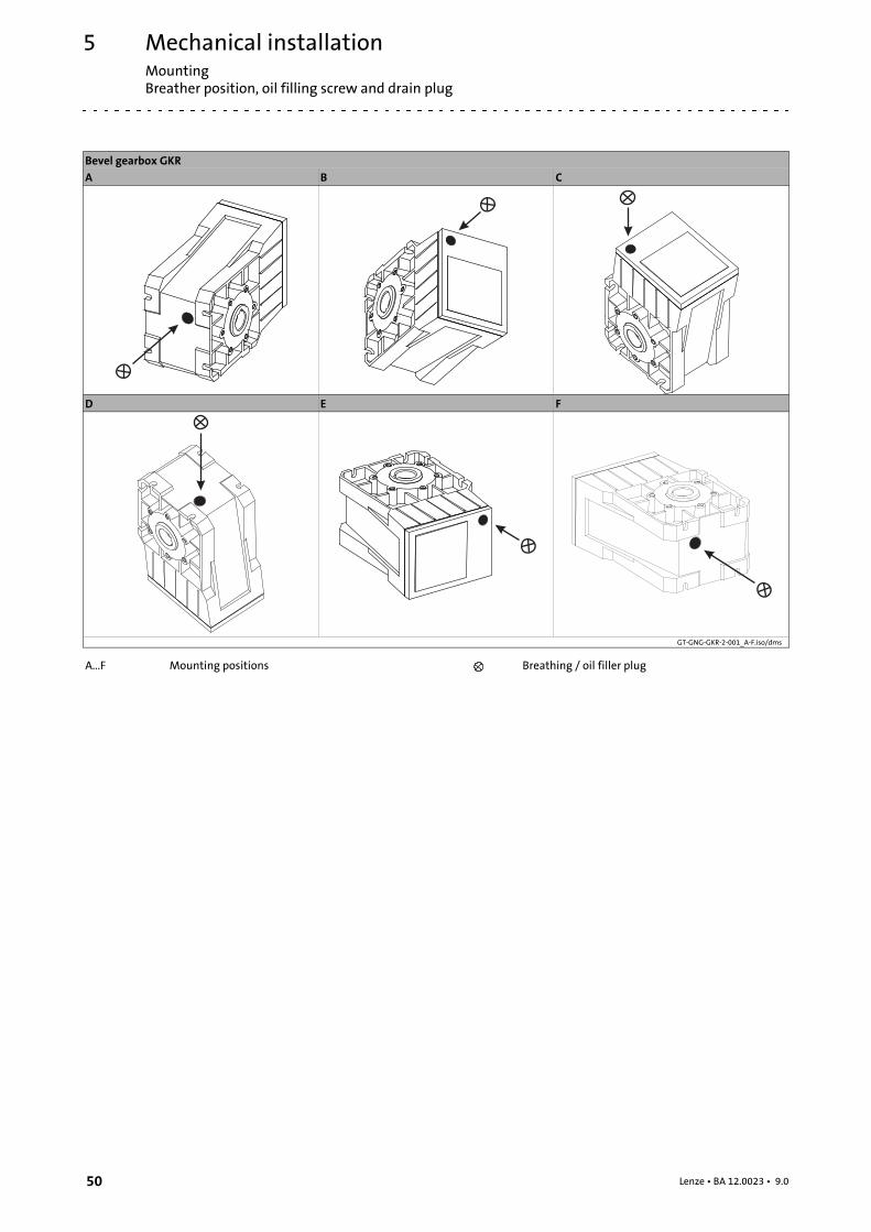
Bevel gearbox GKRA B C
D E F
GT-GNG-GKR-2-001_A-F.iso/dms
A...F Mounting positions Breathing / oil filler plug
Mechanical installationMounting
Breather position, oil filling screw and drain plug
5
51Lenze • BA 12.0023 • 9.0
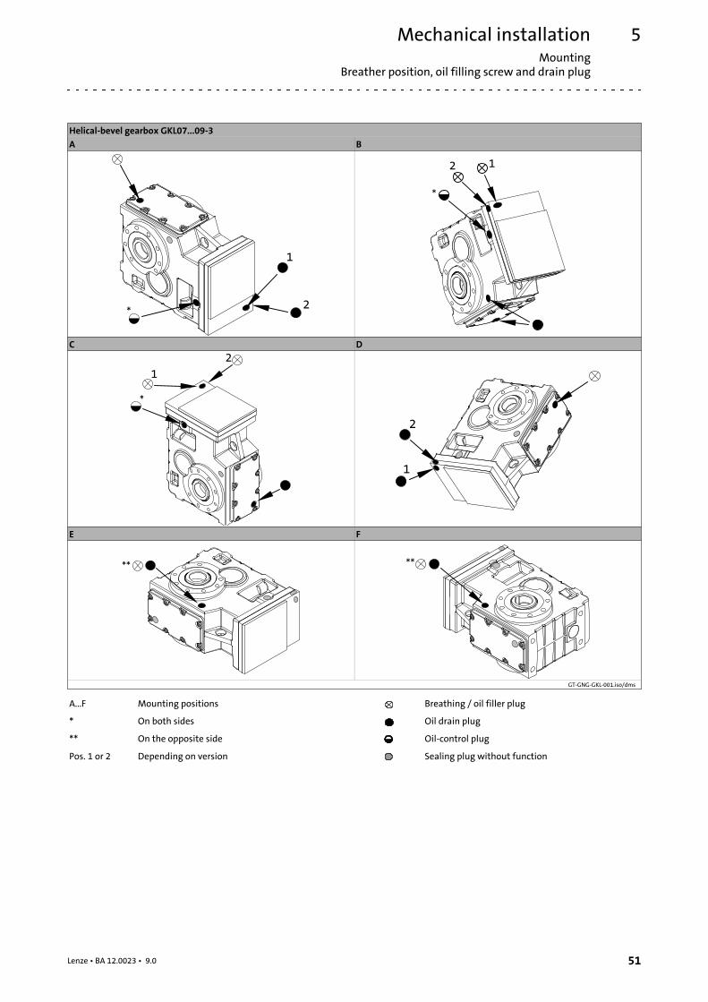
Helical-bevel gearbox GKL07...09-3A B
C D
E F
GT-GNG-GKL-001.iso/dms
A...F Mounting positions Breathing / oil filler plug
* On both sides Oil drain plug
** On the opposite side Oil-control plug
Pos. 1 or 2 Depending on version Sealing plug without function
Mechanical installationMountingGearbox with compensation container for mounting position C
5
52 Lenze • BA 12.0023 • 9.0
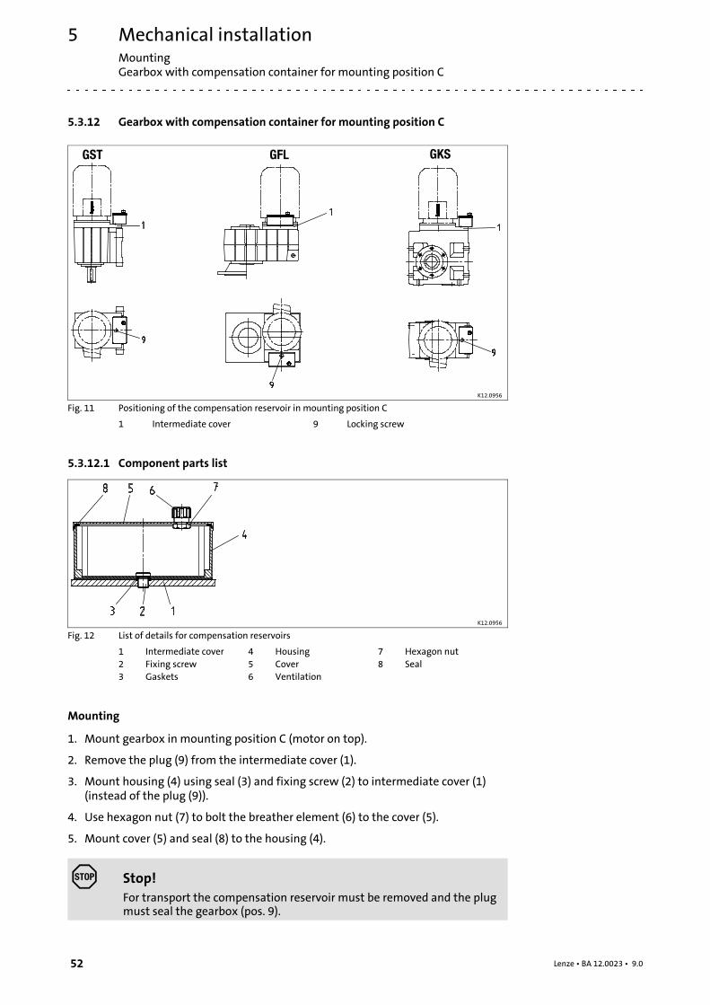
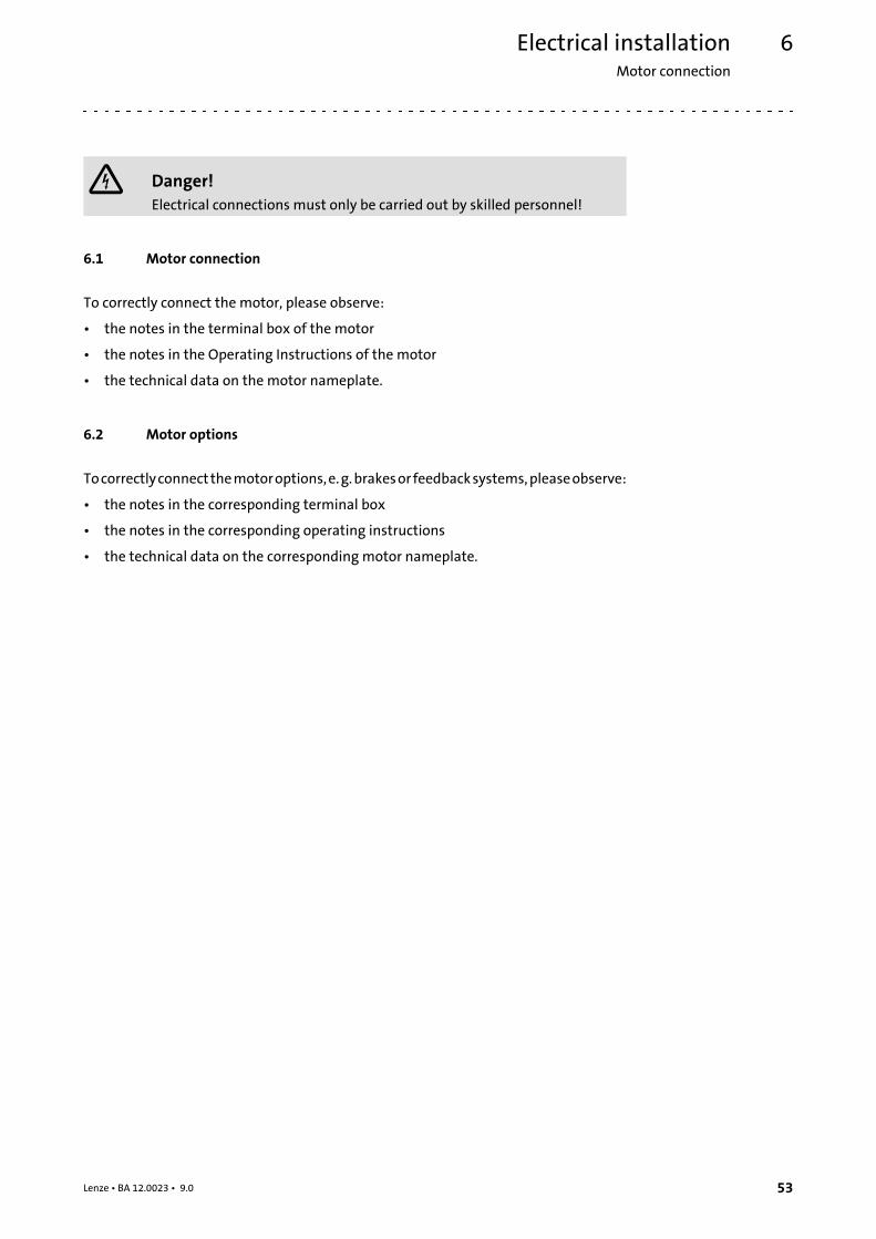
5.3.12 Gearbox with compensation container for mounting position C
GST GFL GKS
K12.0956
Fig. 11 Positioning of the compensation reservoir in mounting position C
1 Intermediate cover 9 Locking screw
5.3.12.1 Component parts list
K12.0956
Fig. 12 List of details for compensation reservoirs
1 Intermediate cover 4 Housing 7 Hexagon nut2 Fixing screw 5 Cover 8 Seal3 Gaskets 6 Ventilation
Mounting
1. Mount gearbox in mounting position C (motor on top).
2. Remove the plug (9) from the intermediate cover (1).
3. Mount housing (4) using seal (3) and fixing screw (2) to intermediate cover (1)(instead of the plug (9)).
4. Use hexagon nut (7) to bolt the breather element (6) to the cover (5).
5. Mount cover (5) and seal (8) to the housing (4).
Stop!For transport the compensation reservoir must be removed and the plugmust seal the gearbox (pos. 9).
Electrical installationMotor connection
6
53Lenze • BA 12.0023 • 9.0
6 Electrical installation
Danger!Electrical connections must only be carried out by skilled personnel!
6.1 Motor connection
To correctly connect the motor, please observe:
• the notes in the terminal box of the motor
• the notes in the Operating Instructions of the motor
• the technical data on the motor nameplate.
6.2 Motor options
Tocorrectlyconnectthemotoroptions,e.g.brakesor feedbacksystems,pleaseobserve:
• the notes in the corresponding terminal box
• the notes in the corresponding operating instructions
• the technical data on the corresponding motor nameplate.
Commissioning and operationBefore switching on
7
54 Lenze • BA 12.0023 • 9.0
7 Commissioning and operation
Stop!The drive may only be commissioned by skilled personnel!
7.1 Before switching on
Please check:
• Does the drive appear undamaged?
• Is the mechanical fixing o.k.?
• Has the electrical connection been carried out properly?
• Are all rotating parts and surfaces that may become hot protected againstcontact?
• If the oil level of the drive has been increased due to storage purposes ( 27), itmust be reduced again to the height permissible for the intended mountingposition.
• For gearboxes with breathing:
– Has the transport locking device been removed?
• For gearboxes with backstop:
– Will the motor start to rotate in the correct direction? ( 28)
7.2 During operation
Note!The helical-worm gearboxes reach their full performance only after ashort running-in period of 24...48 hours at rated torque!
During operation, check the drive periodically and take special care of:
• changes compared to normal operation, like
– unusual noise, stronger vibrations or increased temperatures,
– leakages,
– loose fixing elements,
– the condition of the electrical cables.
• In the event of faults:
– shut down the drive,
– check the troubleshooting table.
If the fault cannot be remedied, please contact the Lenze customer service.
MaintenanceMaintenance intervals
8
55Lenze • BA 12.0023 • 9.0
8 Maintenance
When theyaredelivered, Lenzegearboxesandgearedmotors are filledwithadriveandtype-specific lubricant so that they are ready for production. This initial fillingcorresponds toa lubricant fromthecolumnof the respective Lenzegearbox type.Whentheorder isplaced, themountingpositionandthedesignare thedecisive factors for thelubricant amount.
Note!Gearboxes of sizes 03 and 04 are lubricated for life. Due to the lowthermal load, no lubricant change is required.
8.1 Maintenance intervals
• The mechanical power transmission system is free of maintenance.
• Gearboxes as of size 05 (pre-stages as of size 06) require regular lubricantreplacement.
– The type of lubricant is indicated on the nameplate. Replace the lubricant onlywith the same type.
– The lubricant maintenance interval depends on the oil temperature, see Fig. 13.
• Shaft seals and roller bearings:
– The service life depends on the operating conditions.
– Replace seals in case of leakage to avoid consequential damage.
Note!When changing the lubricant, Lenze recommends also changing thegrease packing of the bearings and replacing the rotary shaft seals!
Stop!For drive systems: Also observe the maintenance intervals for the otherdrive components!
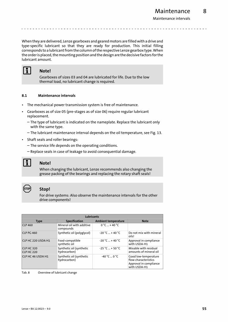
LubricantsType Specification Ambient temperature Note
CLP 460 Mineral oil with additivecompounds
0 °C ... + 40 °C
CLP PG 460 Synthetic oil (polyglycol) -20 °C ... + 40 °C Do not mix with mineraloils!
CLP HC 220 USDA H1 Food-compatiblesynthetic oil
-20 °C ... + 40 °C Approval in compliancewith USDA-H1
CLP HC 320CLP HC 220
Synthetic oil (synthetichydrocarbon)
-25 °C ... + 50 °C Mixable with residualamounts of mineral oil
CLP HC 46 USDA H1 Synthetic oil (synthetichydrocarbon)
-40 °C ... 0 °C Good low-temperatureflow characteristicsApproval in compliancewith USDA-H1
Tab. 8 Overview of lubricant change

MaintenanceMaintenance intervals
8
56 Lenze • BA 12.0023 • 9.0
Note!If ambient temperatures are <-20°C or >+40°C, please contact Lenze!
Observe increased starting torques at low temperatures!
70
80
90
100
1000 10000 100000
16000 h 25000 h
�
�
�
�
GT-GNG-002.iso/dms
Fig. 13 Lubricant diagram
Oil sump temperature [°C] Synthetic oil CLP HC/CLP PG Oil life/changing intervals [operating
hours h] Mineral oil CLP
MaintenanceMaintenance operations
Opening the condensation drain hole
8
57Lenze • BA 12.0023 • 9.0
8.2 Maintenance operations
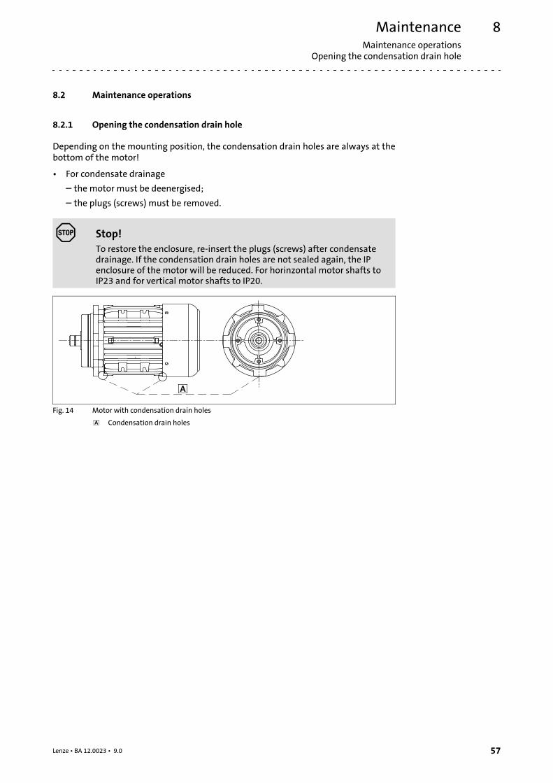
8.2.1 Opening the condensation drain hole
Depending on the mounting position, the condensation drain holes are always at thebottom of the motor!
• For condensate drainage
– the motor must be deenergised;
– the plugs (screws) must be removed.
Stop!To restore the enclosure, re-insert the plugs (screws) after condensatedrainage. If the condensation drain holes are not sealed again, the IPenclosure of the motor will be reduced. For horinzontal motor shafts toIP23 and for vertical motor shafts to IP20.
Fig. 14 Motor with condensation drain holes
Condensation drain holes
MaintenanceMaintenance operationsLubricate roller bearings
8
58 Lenze • BA 12.0023 • 9.0
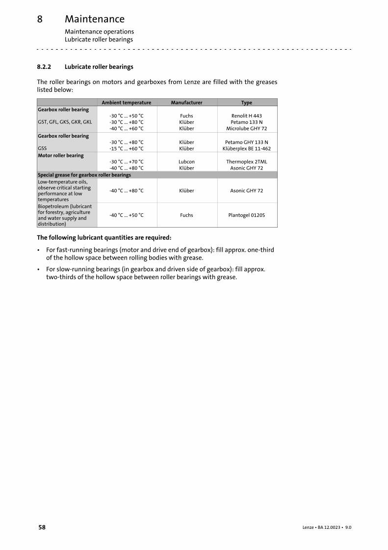
8.2.2 Lubricate roller bearings
The roller bearings on motors and gearboxes from Lenze are filled with the greaseslisted below:
Ambient temperature Manufacturer TypeGearbox roller bearing
GST, GFL, GKS, GKR, GKL-30 °C ... +50 °C-30 °C ... +80 °C-40 °C ... +60 °C
FuchsKlüberKlüber
Renolit H 443Petamo 133 N
Microlube GHY 72
Gearbox roller bearing
GSS-30 °C ... +80 °C-15 °C ... +60 °C
KlüberKlüber
Petamo GHY 133 NKlüberplex BE 11-462
Motor roller bearing-30 °C ... +70 °C-40 °C ... +80 °C
LubconKlüber
Thermoplex 2TMLAsonic GHY 72
Special grease for gearbox roller bearingsLow-temperature oils,observe critical startingperformance at lowtemperatures
-40 °C ... +80 °C Klüber Asonic GHY 72
Biopetroleum (lubricantfor forestry, agricultureand water supply anddistribution)
-40 °C ... +50 °C Fuchs Plantogel 0120S
The following lubricant quantities are required:
• For fast-running bearings (motor and drive end of gearbox): fill approx. one-thirdof the hollow space between rolling bodies with grease.
• For slow-running bearings (in gearbox and driven side of gearbox): fill approx.two-thirds of the hollow space between roller bearings with grease.

MaintenanceMaintenance operations
Table of lubricants
8
59Lenze • BA 12.0023 • 9.0
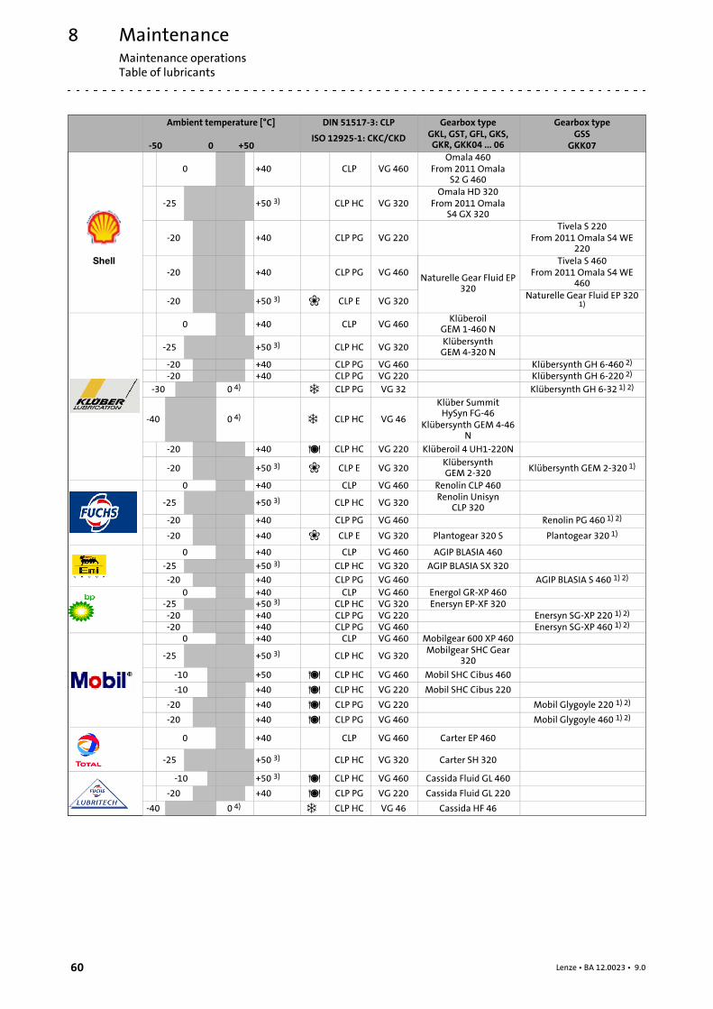
8.2.3 Table of lubricants
Note!Please note that the recommendation of a lubricant/grease or its listingin a Lenze lubricant table does not mean that Lenze is liable for theselubricants or damages resulting from incompatibilities of materials used.
For Lenze drives, the lubricants listed in the lubricant table on the following page arepermitted. Special lubricants must be used, for instance for longtime storage orspecial operating conditions. These corresponding lubricants are available at asurcharge.
For the lubricant selection observe the following legend relating to the lubricanttable!
CLP Mineral oilCLP PG Polyglycol oilCLP PAO Synthetic hydrocarbons or poly-alpha-olefin oilCLP E Diester oil (water pollution class 1)1) Currently no test results are provided yet for the efficiency of the specified
lubricants for worm gearbox lubrication. If these oils are used, the permissibletorque must be reduced to 80% of the catalogue values.
2) Polyglycol oils cannot be mixed with other types of oil3) For ambient temperatures above 40°C please consult us and specify the exact
operating conditions!4) Observe critical starting performance at low temperatures! Temperatures below
-25°C require special measures for the motor bearing and NBR shaft sealingrings!
5) Ambient temperature range
Food-grade lubricant
Biopetroleum (lubricant for forestry, agriculture and water supply anddistribution)
Low-temperature oils, observe critical starting performance at lowtemperatures!
MaintenanceMaintenance operationsTable of lubricants
8
60 Lenze • BA 12.0023 • 9.0
Ambient temperature [°C]
-50 0 +50
DIN 51517-3: CLP
ISO 12925-1: CKC/CKD
Gearbox typeGKL, GST, GFL, GKS,GKR, GKK04 ... 06
Gearbox typeGSS
GKK07
pÜÉää
0 +40 CLP VG 460Omala 460
From 2011 OmalaS2 G 460
-25 +50 3) CLP HC VG 320Omala HD 320
From 2011 OmalaS4 GX 320
-20 +40 CLP PG VG 220Tivela S 220
From 2011 Omala S4WE220
-20 +40 CLP PG VG 460Naturelle Gear Fluid EP
320
Tivela S 460From 2011 Omala S4WE
460
-20 +50 3) CLP E VG 320Naturelle Gear Fluid EP 320
1)
0 +40 CLP VG 460Klüberoil
GEM 1-460 N
-25 +50 3) CLP HC VG 320KlübersynthGEM 4-320 N
-20 +40 CLP PG VG 460 Klübersynth GH 6-460 2)
-20 +40 CLP PG VG 220 Klübersynth GH 6-220 2)
-30 0 4) CLP PG VG 32 Klübersynth GH 6-32 1) 2)
-40 0 4) CLP HC VG 46
Klüber SummitHySyn FG-46
Klübersynth GEM 4-46N
-20 +40 CLP HC VG 220 Klüberoil 4 UH1-220N
-20 +50 3) CLP E VG 320KlübersynthGEM 2-320 Klübersynth GEM 2-320 1)
0 +40 CLP VG 460 Renolin CLP 460
-25 +50 3) CLP HC VG 320Renolin Unisyn
CLP 320-20 +40 CLP PG VG 460 Renolin PG 460 1) 2)
-20 +40 CLP E VG 320 Plantogear 320 S Plantogear 320 1)
0 +40 CLP VG 460 AGIP BLASIA 460
-25 +50 3) CLP HC VG 320 AGIP BLASIA SX 320
-20 +40 CLP PG VG 460 AGIP BLASIA S 460 1) 2)
0 +40 CLP VG 460 Energol GR-XP 460-25 +50 3) CLP HC VG 320 Enersyn EP-XF 320-20 +40 CLP PG VG 220 Enersyn SG-XP 220 1) 2)
-20 +40 CLP PG VG 460 Enersyn SG-XP 460 1) 2)
0 +40 CLP VG 460 Mobilgear 600 XP 460
-25 +50 3) CLP HC VG 320Mobilgear SHC Gear
320
-10 +50 CLP HC VG 460 Mobil SHC Cibus 460
-10 +40 CLP HC VG 220 Mobil SHC Cibus 220
-20 +40 CLP PG VG 220 Mobil Glygoyle 220 1) 2)
-20 +40 CLP PG VG 460 Mobil Glygoyle 460 1) 2)
0 +40 CLP VG 460 Carter EP 460
-25 +50 3) CLP HC VG 320 Carter SH 320
-10 +50 3) CLP HC VG 460 Cassida Fluid GL 460
-20 +40 CLP PG VG 220 Cassida Fluid GL 220
-40 0 4) CLP HC VG 46 Cassida HF 46
MaintenanceMaintenance operationsReplacing the lubricant
8
61Lenze • BA 12.0023 • 9.0
Gearbox typeGSS
GKK07
Gearbox typeGKL, GST, GFL, GKS,GKR, GKK04 ... 06
DIN 51517-3: CLP
ISO 12925-1: CKC/CKD
Ambient temperature [°C]
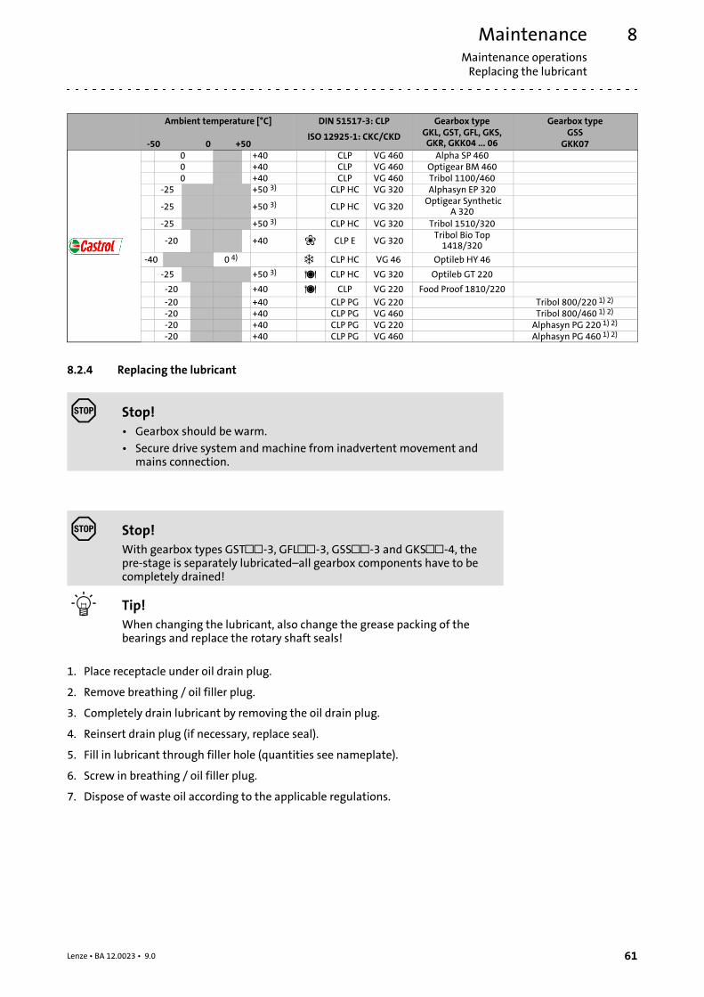
-50 0 +500 +40 CLP VG 460 Alpha SP 4600 +40 CLP VG 460 Optigear BM 4600 +40 CLP VG 460 Tribol 1100/460
-25 +50 3) CLP HC VG 320 Alphasyn EP 320
-25 +50 3) CLP HC VG 320Optigear Synthetic
A 320-25 +50 3) CLP HC VG 320 Tribol 1510/320
-20 +40 CLP E VG 320Tribol Bio Top1418/320
-40 0 4) CLP HC VG 46 Optileb HY 46
-25 +50 3) CLP HC VG 320 Optileb GT 220
-20 +40 CLP VG 220 Food Proof 1810/220-20 +40 CLP PG VG 220 Tribol 800/220 1) 2)
-20 +40 CLP PG VG 460 Tribol 800/460 1) 2)
-20 +40 CLP PG VG 220 Alphasyn PG 220 1) 2)
-20 +40 CLP PG VG 460 Alphasyn PG 460 1) 2)
8.2.4 Replacing the lubricant
Stop!• Gearbox should be warm.
• Secure drive system andmachine from inadvertent movement andmains connection.
Stop!With gearbox types GST-3, GFL-3, GSS-3 and GKS-4, thepre-stage is separately lubricated–all gearbox components have to becompletely drained!
Tip!When changing the lubricant, also change the grease packing of thebearings and replace the rotary shaft seals!
1. Place receptacle under oil drain plug.
2. Remove breathing / oil filler plug.
3. Completely drain lubricant by removing the oil drain plug.
4. Reinsert drain plug (if necessary, replace seal).
5. Fill in lubricant through filler hole (quantities see nameplate).
6. Screw in breathing / oil filler plug.
7. Dispose of waste oil according to the applicable regulations.
MaintenanceMaintenance operationsLubricant quantity
8
62 Lenze • BA 12.0023 • 9.0
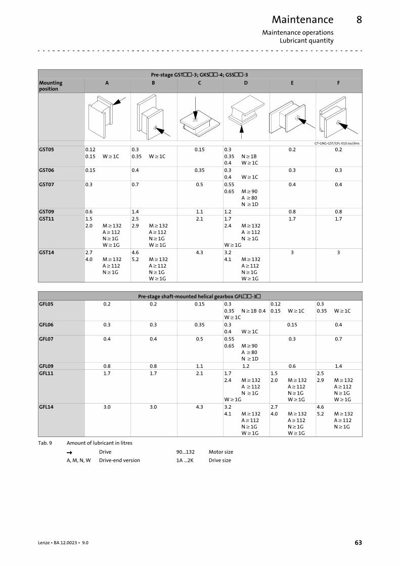
8.2.5 Lubricant quantity
Stop!At drive speeds below 200 rpm the amount of lubricant may need to beincreased. Consultation with Lenze is required.
MaintenanceMaintenance operations
Lubricant quantity
8
63Lenze • BA 12.0023 • 9.0
Pre-stage GST-3; GKS-4; GSS-3Mountingposition
A B C D E F
GT-GNG-GST/GFL-010.iso/dms
GST05 0.120.15 W≥1C
0.30.35 W≥1C
0.15 0.30.35 N≥1B0.4 W≥1C
0.2 0.2
GST06 0.15 0.4 0.35 0.30.4 W≥1C
0.3 0.3
GST07 0.3 0.7 0.5 0.550.65 M≥90
A≥80N≥1D
0.4 0.4
GST09 0.6 1.4 1.1 1.2 0.8 0.8GST11 1.5
2.0 M≥132A≥112N≥1GW≥1G
2.52.9 M≥132
A≥112N≥1GW≥1G
2.1 1.72.4 M≥132
A≥112N≥1G
W≥1G
1.7 1.7
GST14 2.74.0 M≥132
A≥112N≥1G
4.65.2 M≥132
A≥112N≥1GW≥1G
4.3 3.24.1 M≥132
A≥112N≥1GW≥1G
3 3
Pre-stage shaft-mounted helical gearbox GFL-3GFL05 0.2 0.2 0.15 0.3
0.35 N≥1B 0.4W≥1C
0.120.15 W≥1C
0.30.35 W≥1C
GFL06 0.3 0.3 0.35 0.30.4 W≥1C
0.15 0.4
GFL07 0.4 0.4 0.5 0.550.65 M≥90
A≥80N≥1D
0.3 0.7
GFL09 0.8 0.8 1.1 1.2 0.6 1.4GFL11 1.7 1.7 2.1 1.7
2.4 M≥132A≥112N≥1G
W≥1G
1.52.0 M≥132
A≥112N≥1GW≥1G
2.52.9 M≥132
A≥112N≥1GW≥1G
GFL14 3.0 3.0 4.3 3.24.1 M≥132
A≥112N≥1GW≥1G
2.74.0 M≥132
A≥112N≥1GW≥1G
4.65.2 M≥132
A≥112N≥1G
Tab. 9 Amount of lubricant in litres
Drive 90...132 Motor size
A, M, N, W Drive-end version 1A ...2K Drive size
MaintenanceMaintenance operationsLubricant quantity
8
64 Lenze • BA 12.0023 • 9.0
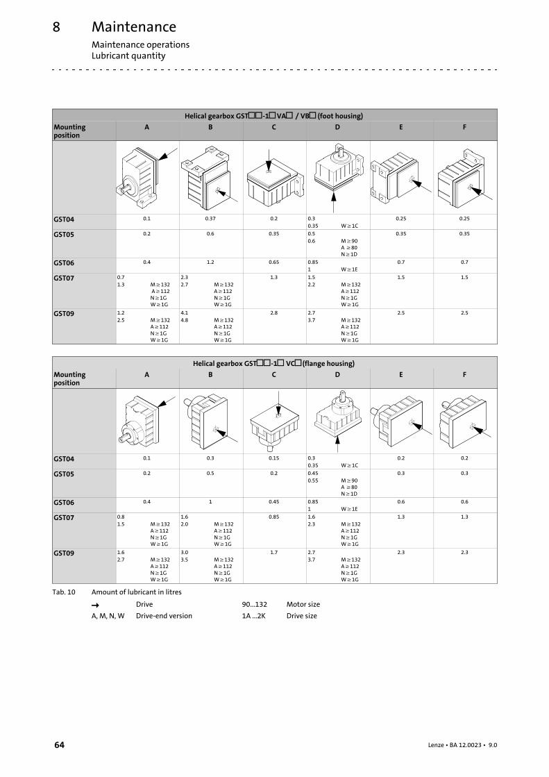
Helical gearbox GST-1VA / VB(foot housing)Mountingposition
A B C D E F
GST04 0.1 0.37 0.2 0.30.35 W≥1C
0.25 0.25
GST05 0.2 0.6 0.35 0.50.6 M≥90
A≥80N≥1D
0.35 0.35
GST06 0.4 1.2 0.65 0.851 W≥1E
0.7 0.7
GST07 0.71.3 M≥132
A≥112N≥1GW≥1G
2.32.7 M≥132
A≥112N≥1GW≥1G
1.3 1.52.2 M≥132
A≥112N≥1GW≥1G
1.5 1.5
GST09 1.22.5 M≥132
A≥112N≥1GW≥1G
4.14.8 M≥132
A≥112N≥1GW≥1G
2.8 2.73.7 M≥132
A≥112N≥1GW≥1G
2.5 2.5
Helical gearbox GST-1 VC(flange housing)Mountingposition
A B C D E F
GST04 0.1 0.3 0.15 0.30.35 W≥1C
0.2 0.2
GST05 0.2 0.5 0.2 0.450.55 M≥90
A≥80N≥1D
0.3 0.3
GST06 0.4 1 0.45 0.851 W≥1E
0.6 0.6
GST07 0.81.5 M≥132
A≥112N≥1GW≥1G
1.62.0 M≥132
A≥112N≥1GW≥1G
0.85 1.62.3 M≥132
A≥112N≥1GW≥1G
1.3 1.3
GST09 1.62.7 M≥132
A≥112N≥1GW≥1G
3.03.5 M≥132
A≥112N≥1GW≥1G
1.7 2.73.7 M≥132
A≥112N≥1GW≥1G
2.3 2.3
Tab. 10 Amount of lubricant in litres
Drive 90...132 Motor size
A, M, N, W Drive-end version 1A ...2K Drive size

MaintenanceMaintenance operations
Lubricant quantity
8
65Lenze • BA 12.0023 • 9.0
Helical gearbox GST-2; -3 VA / VB(foot housing)Mountingposition
A B C D E F
GST03 0.2 0.2 0.2 0.2 0.2 0.2
GST04 0.35 0.5 0.45 0.55 0.3 0.3
GST05 0.5 0.80 0.75 1 0.55 0.55
GST06 0.60.7 M≥132
1.11.2 M≥132
1.2 1.71.8 M≥132
1.01.1 M≥132
1.01.1 M≥132
GST07 2.22.6 M≥132
A≥112N≥1GW≥1G
2.52.9 M≥132
A≥112N≥1GW≥1G
2.6 33.7 M≥132
A≥112N≥1GW≥1G
1.72.1 M≥132
A≥112N≥1GW≥1G
1.72.1 M≥132
A≥112N≥1GW≥1G
GST09 4.24.8 M≥132
A≥112N≥1GW≥1G
5.35.9 M≥132
A≥112N≥1GW≥1G
5.4 6.17.3 M≥132
A≥112N≥1GW≥1G
3.13.7 M≥132
A≥112N≥1GW≥1G
3.13.7 M≥132
A≥112N≥1GW≥1G
GST11 8.5 9.5 10 11.5 7 7
GST14 15 18 18 20 11 11
Helical gearbox GST-2; -3VC(flange housing)Mountingposition
A B C D E F
GST03 0.17 0.17 0.17 0.17 0.17 0.17
GST04 0.35 0.45 0.3 0.6 0.3 0.3
GST05 0.45 0.7 0.6 0.95 0.45 0.45
GST06 0.50.6 M≥132
0.91.0 M≥132
1.1 1.61.7 M≥132
0.91.0 M≥132
0.91.0 M≥132
GST07 1.82.2 M≥132
A≥112N≥1GW≥1G
2.42.8 M≥132
A≥112N≥1GW≥1G
2.2 2.73.4 M≥132
A≥112N≥1GW≥1G
1.51.9 M≥132
A≥112N≥1GW≥1G
1.51.9 M≥132
A≥112N≥1GW≥1G
GST09 3.54.1 M≥132
A≥112N≥1GW≥1G
4.55.0 M≥132
A≥112N≥1GW≥1G
4.4 5.56.7 M≥132
A≥112N≥1GW≥1G
2.83.4 M≥132
A≥112N≥1GW≥1G
2.83.4 M≥132
A≥112N≥1GW≥1G
GST11 7.5 8.5 8.0 10.5 6 6
GST14 13 16 14 18 9.5 9.5
Tab. 11 Amount of lubricant in litres
Drive 90...132 Motor size
A, M, N, W Drive-end version 1A ...2K Drive size
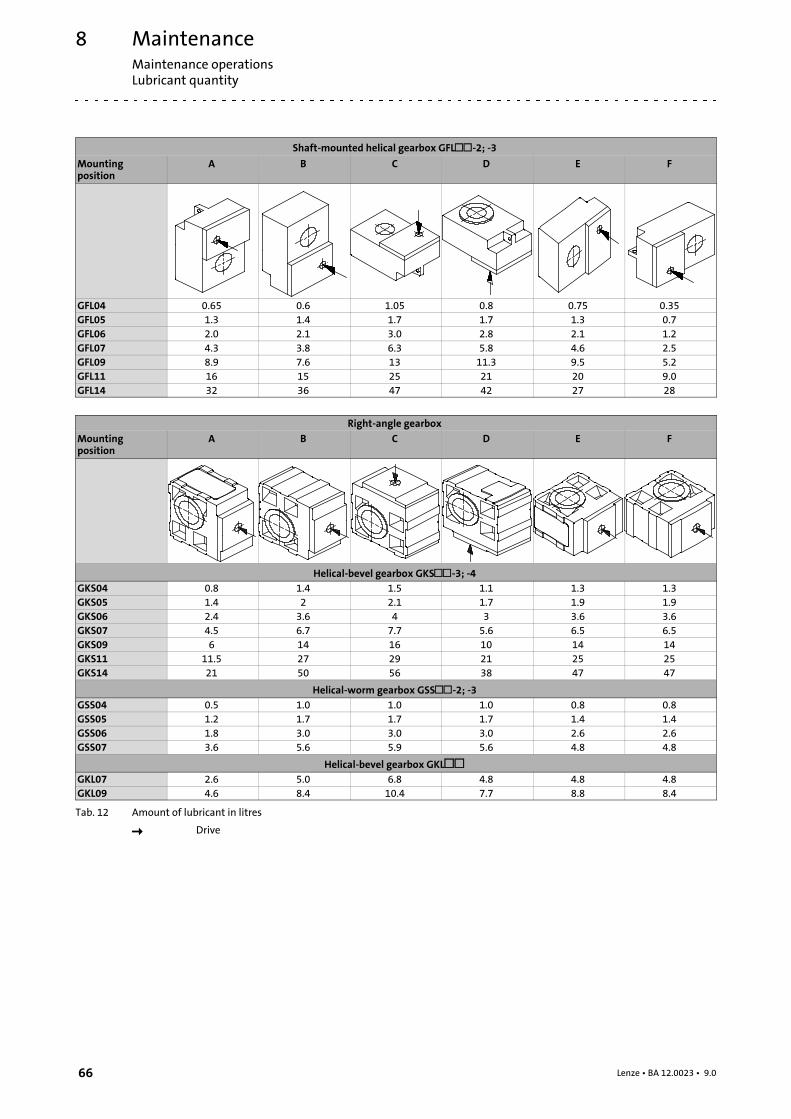
MaintenanceMaintenance operationsLubricant quantity
8
66 Lenze • BA 12.0023 • 9.0
Shaft-mounted helical gearbox GFL-2; -3Mountingposition
A B C D E F
GFL04 0.65 0.6 1.05 0.8 0.75 0.35GFL05 1.3 1.4 1.7 1.7 1.3 0.7GFL06 2.0 2.1 3.0 2.8 2.1 1.2GFL07 4.3 3.8 6.3 5.8 4.6 2.5GFL09 8.9 7.6 13 11.3 9.5 5.2GFL11 16 15 25 21 20 9.0GFL14 32 36 47 42 27 28
Right-angle gearboxMountingposition
A B C D E F
Helical-bevel gearbox GKS-3; -4GKS04 0.8 1.4 1.5 1.1 1.3 1.3GKS05 1.4 2 2.1 1.7 1.9 1.9GKS06 2.4 3.6 4 3 3.6 3.6GKS07 4.5 6.7 7.7 5.6 6.5 6.5GKS09 6 14 16 10 14 14GKS11 11.5 27 29 21 25 25GKS14 21 50 56 38 47 47
Helical-worm gearbox GSS-2; -3GSS04 0.5 1.0 1.0 1.0 0.8 0.8GSS05 1.2 1.7 1.7 1.7 1.4 1.4GSS06 1.8 3.0 3.0 3.0 2.6 2.6GSS07 3.6 5.6 5.9 5.6 4.8 4.8
Helical-bevel gearbox GKLGKL07 2.6 5.0 6.8 4.8 4.8 4.8GKL09 4.6 8.4 10.4 7.7 8.8 8.4
Tab. 12 Amount of lubricant in litres
Drive

MaintenanceMaintenance operations
Lubricant quantity
8
67Lenze • BA 12.0023 • 9.0
Bevel gearbox GKRMounting position A B C
GKR03 0.35 0.35 0.35 / 0.4 *GKR04 0.4 0.5 0.7 / 0.8 *GKR05 0.8 1.3 1.5 / 1.6 *GKR06 1.5 2.3 3.0 / 3.2 *
Mounting position D E F
GKR03 0.35 0.35 0.35GKR04 0.7 0.6 0.4GKR05 1.4 1.5 1.0GKR06 2.6 3.0 1.8
Tab. 13 Amount of lubricant in litres
* with version VK at the output end
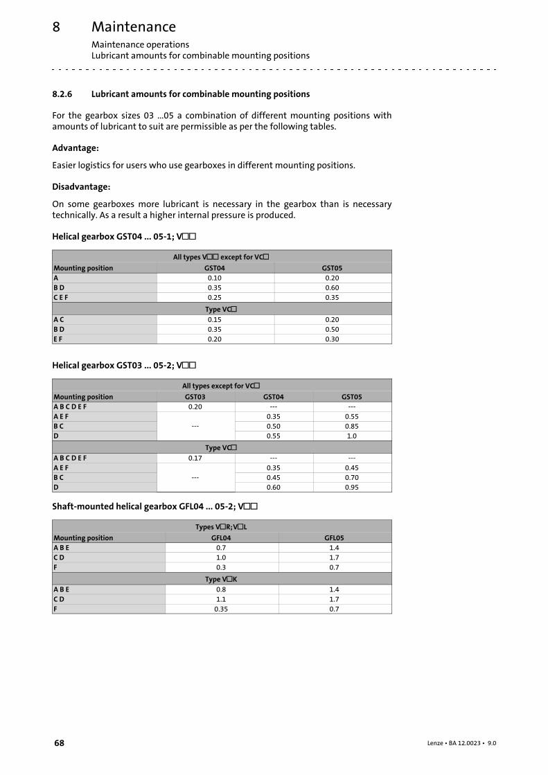
MaintenanceMaintenance operationsLubricant amounts for combinable mounting positions
8
68 Lenze • BA 12.0023 • 9.0
8.2.6 Lubricant amounts for combinable mounting positions
For the gearbox sizes 03 ...05 a combination of different mounting positions withamounts of lubricant to suit are permissible as per the following tables.
Advantage:
Easier logistics for users who use gearboxes in different mounting positions.
Disadvantage:
On some gearboxes more lubricant is necessary in the gearbox than is necessarytechnically. As a result a higher internal pressure is produced.
Helical gearbox GST04 ... 05-1; V
All types V except for VCMounting position GST04 GST05A 0.10 0.20B D 0.35 0.60C E F 0.25 0.35
Type VCA C 0.15 0.20B D 0.35 0.50E F 0.20 0.30
Helical gearbox GST03 ... 05-2; V
All types except for VCMounting position GST03 GST04 GST05A B C D E F 0.20 --- ---A E F
---0.35 0.55
B C 0.50 0.85D 0.55 1.0
Type VCA B C D E F 0.17 --- ---A E F
---0.35 0.45
B C 0.45 0.70D 0.60 0.95
Shaft-mounted helical gearbox GFL04 ... 05-2; V
Types VR;VLMounting position GFL04 GFL05A B E 0.7 1.4C D 1.0 1.7F 0.3 0.7
Type VKA B E 0.8 1.4C D 1.1 1.7F 0.35 0.7
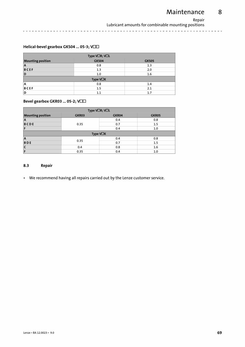
MaintenanceRepair
Lubricant amounts for combinable mounting positions
8
69Lenze • BA 12.0023 • 9.0
Helical-bevel gearbox GKS04 ... 05-3; V
Type VR; VLMounting position GKS04 GKS05A 0.8 1.3B C E F 1.3 2.0D 1.0 1.6
Type VKA 0.8 1.4B C E F 1.5 2.1D 1.1 1.7
Bevel gearbox GKR03 ... 05-2; V
Type VR; VLMounting position GKR03 GKR04 GKR05A
0.350.4 0.8
B C D E 0.7 1.5F 0.4 1.0
Type VKA
0.350.4 0.8
B D E 0.7 1.5C 0.4 0.8 1.6F 0.35 0.4 1.0
8.3 Repair
• We recommend having all repairs carried out by the Lenze customer service.
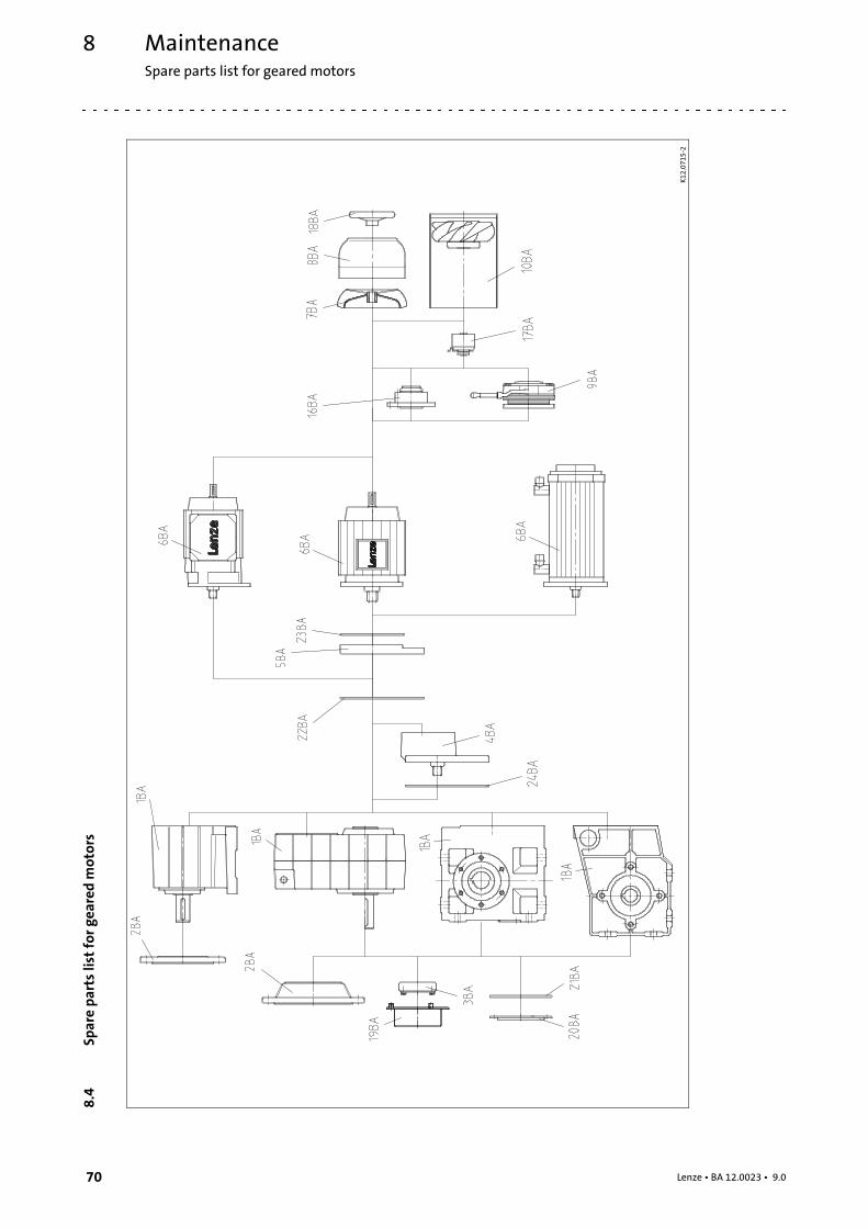
MaintenanceSpare parts list for geared motors
8
70 Lenze • BA 12.0023 • 9.0
8.4
Sparepartslistforg
earedmotors
K12
.071
5-2
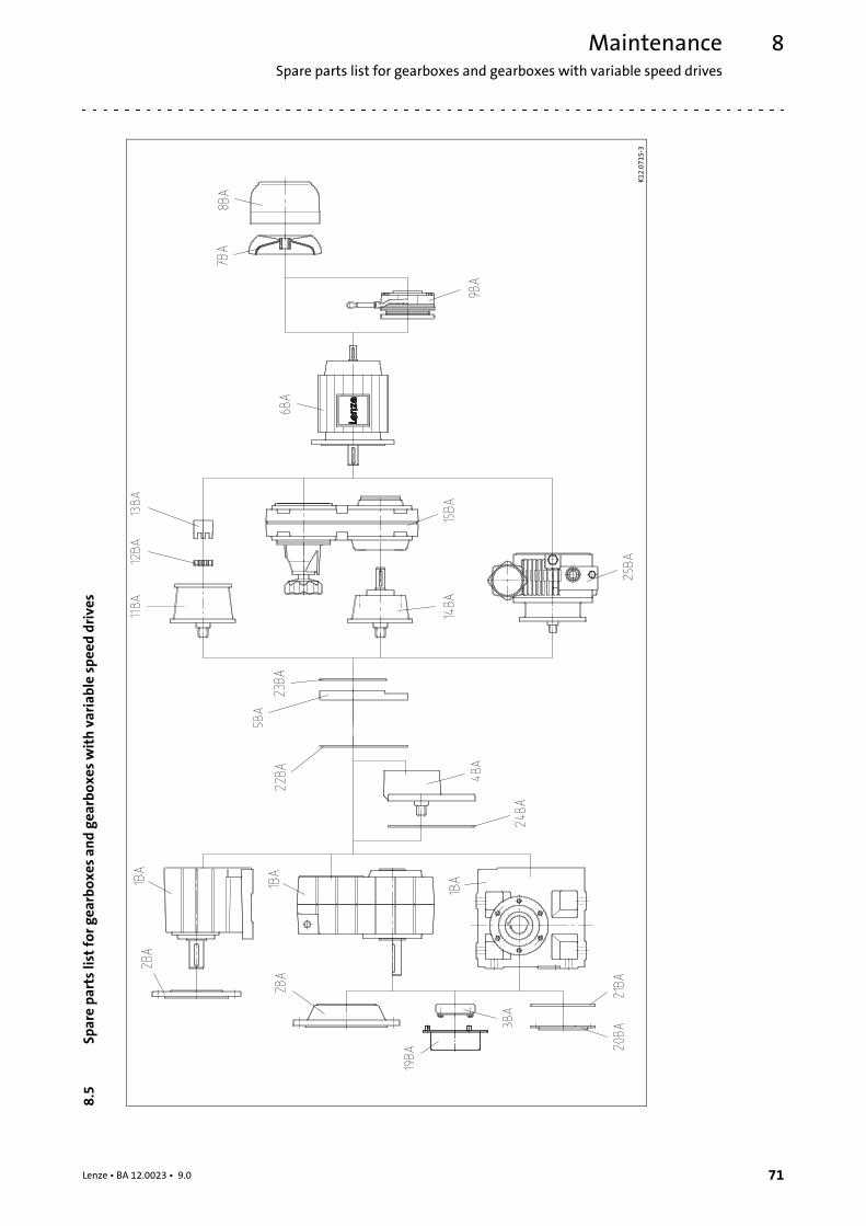
MaintenanceSpare parts list for gearboxes and gearboxes with variable speed drives
8
71Lenze • BA 12.0023 • 9.0
8.5
Sparepartslistforg
earboxes
andgearbo
xeswithvariablespeeddrives
K12
.071
5-3
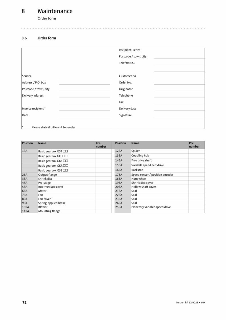
MaintenanceOrder form
8
72 Lenze • BA 12.0023 • 9.0
8.6 Order form
Recipient: Lenze
Postcode / town, city:
Telefax No.:
Sender Customer no.
Address / P.O. box Order No.
Postcode / town, city Originator
Delivery address Telephone
Fax
Invoice recipient * Delivery date
Date Signature
* Please state if different to sender
Position Name Pce.number
Position Name Pce.number
1BA Basic gearbox GST 12BA Spider
Basic gearbox GFL 13BA Coupling hub
Basic gearbox GKS 14BA Free drive shaft
Basic gearbox GKR 15BA Variable speed belt drive
Basic gearbox GSS 16BA Backstop
2BA Output flange 17BA Speed sensor / position encoder3BA Shrink disc 18BA Handwheel4BA Pre-stage 19BA Shrink disc cover5BA Intermediate cover 20BA Hollow shaft cover6BA Motor 21BA Seal7BA Fan 22BA Seal8BA Fan cover 23BA Seal9BA Spring-applied brake 24BA Seal10BA Blower 25BA Planetary variable speed drive11BA Mounting flange
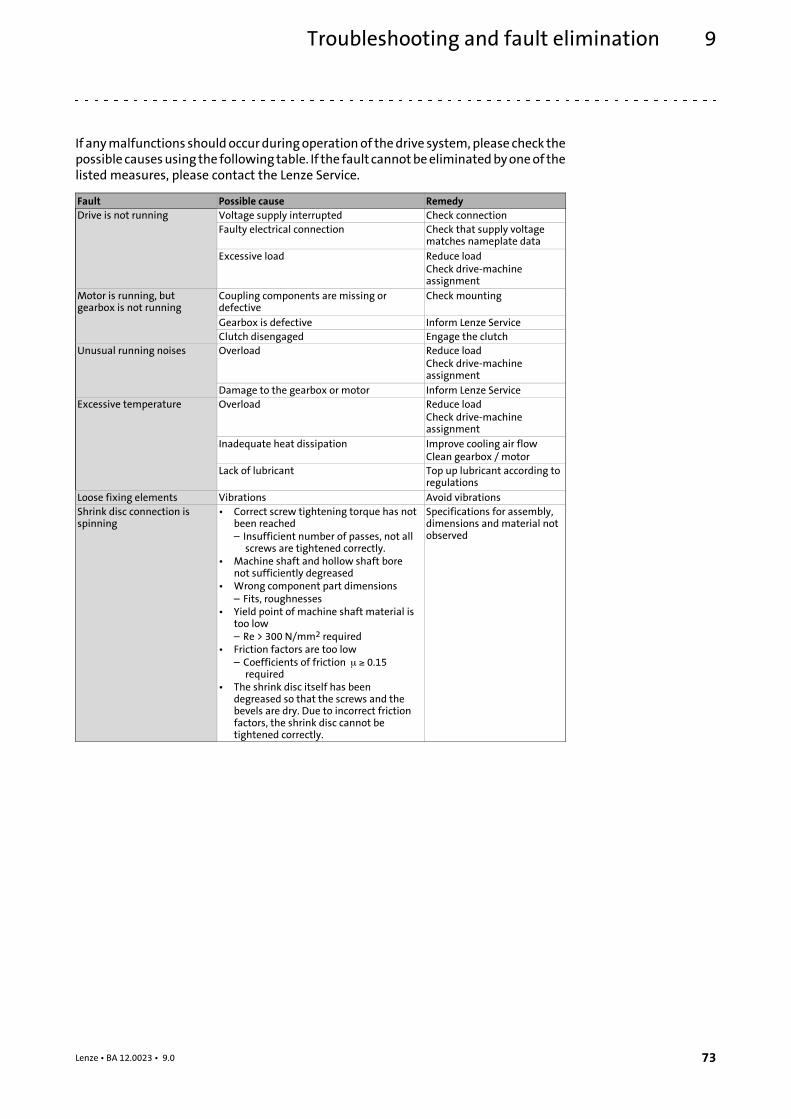
Troubleshooting and fault elimination 9
73Lenze • BA 12.0023 • 9.0
9 Troubleshooting and fault elimination
If anymalfunctions shouldoccurduringoperationof thedrive system,please check thepossible causesusing the following table. If the fault cannotbeeliminatedbyoneof thelisted measures, please contact the Lenze Service.
Fault Possible cause RemedyDrive is not running Voltage supply interrupted Check connection
Faulty electrical connection Check that supply voltagematches nameplate data
Excessive load Reduce loadCheck drive-machineassignment
Motor is running, butgearbox is not running
Coupling components are missing ordefective
Check mounting
Gearbox is defective Inform Lenze ServiceClutch disengaged Engage the clutch
Unusual running noises Overload Reduce loadCheck drive-machineassignment
Damage to the gearbox or motor Inform Lenze ServiceExcessive temperature Overload Reduce load
Check drive-machineassignment
Inadequate heat dissipation Improve cooling air flowClean gearbox / motor
Lack of lubricant Top up lubricant according toregulations
Loose fixing elements Vibrations Avoid vibrationsShrink disc connection isspinning
• Correct screw tightening torque has notbeen reached– Insufficient number of passes, not allscrews are tightened correctly.
• Machine shaft and hollow shaft borenot sufficiently degreased
• Wrong component part dimensions– Fits, roughnesses
• Yield point of machine shaft material istoo low– Re > 300 N/mm2 required
• Friction factors are too low– Coefficients of friction 0.15required
• The shrink disc itself has beendegreased so that the screws and thebevels are dry. Due to incorrect frictionfactors, the shrink disc cannot betightened correctly.
Specifications for assembly,dimensions and material notobserved

Notes
74 Lenze • BA 12.0023 • 9.0

Notes
75Lenze • BA 12.0023 • 9.0

© 11/2015 | BA 12.0023 |.S>, | 9.0 | TD09
Lenze Drives GmbHPostfach 10 13 52, 31763 HamelnBreslauer Straße 3, 32699 ExtertalGERMANYHR Lemgo B 6478
+49 5154 82-0
+49 5154 82-2800
www.lenze.com
Lenze Service GmbHBreslauer Straße 3, D-32699 Extertal
Germany
0080002446877 (24 h helpline)
+49 5154 82-1112
10 9 8 7 6 5 4 3 2 1