Embed Size (px)
Citation preview
Pneumatic PositionerType 3766
Mounting andOperating Instructions
EB 8355-1 ENEdition March 2004
Fig. 1 ⋅ Type 3766
Contents
Contents Page
1 Design and principle of operation . . . . . . . . . . . . . . . . . . . . . . 4
1.1 Versions . . . . . . . . . . . . . . . . . . . . . . . . . . . . . . . . . . . 7
1.2 Technical data . . . . . . . . . . . . . . . . . . . . . . . . . . . . . . . . 8
2 Attachment to control valve . . . . . . . . . . . . . . . . . . . . . . . . . 10
2.1 Direct attachment to Type 3277 Actuator . . . . . . . . . . . . . . . . . . . 10
2.2 Attachment according to IEC 60534-6 . . . . . . . . . . . . . . . . . . . . 152.2.1 Mounting sequence . . . . . . . . . . . . . . . . . . . . . . . . . . . . . 162.2.2 Presetting the travel . . . . . . . . . . . . . . . . . . . . . . . . . . . . . 16
2.3 Attachment to rotary actuators . . . . . . . . . . . . . . . . . . . . . . . . 192.3.1 Mounting the cam follower lever . . . . . . . . . . . . . . . . . . . . . . . 202.3.2 Mounting the intermediate piece . . . . . . . . . . . . . . . . . . . . . . . 202.3.3 Default setting of the cam disk . . . . . . . . . . . . . . . . . . . . . . . . 222.3.4 Reversing amplifier for double-acting actuators . . . . . . . . . . . . . . . . 26
3 Connections . . . . . . . . . . . . . . . . . . . . . . . . . . . . . . . . . 28
3.1 Pneumatic connections . . . . . . . . . . . . . . . . . . . . . . . . . . . . 283.1.1 Pressure gauge . . . . . . . . . . . . . . . . . . . . . . . . . . . . . . . 283.1.2 Supply pressure . . . . . . . . . . . . . . . . . . . . . . . . . . . . . . . 28
3.2 Electrical connections . . . . . . . . . . . . . . . . . . . . . . . . . . . . 293.2.1 Switching amplifiers . . . . . . . . . . . . . . . . . . . . . . . . . . . . . 30
4 Operation . . . . . . . . . . . . . . . . . . . . . . . . . . . . . . . . . . 31
4.1 Adjusting the positioner at the valve . . . . . . . . . . . . . . . . . . . . . 314.1.1 Adjusting the proportional band Xp and air delivery Q . . . . . . . . . . . . 324.1.2 Adjusting the actuator: "Actuator stem extends" . . . . . . . . . . . . . . . . 324.1.3 Adjusting the actuator: "Actuator stem retracts" . . . . . . . . . . . . . . . . 33
4.2 Changing the operating direction . . . . . . . . . . . . . . . . . . . . . . . 34
4.3 Adjusting the limit switches . . . . . . . . . . . . . . . . . . . . . . . . . . 35
4.4 Adjusting the position transmitter . . . . . . . . . . . . . . . . . . . . . . . 37
5 Converting and retrofitting the positioner . . . . . . . . . . . . . . . . . . 39
6 Dimensions in mm . . . . . . . . . . . . . . . . . . . . . . . . . . . . . . 40
Test certificates . . . . . . . . . . . . . . . . . . . . . . . . . . . . . . . 41
2 EB 8355-1 EN
Note!Positioners with model index 3766-x...x. 03 and higher are equipped with a hinged coverwithout vent connection. The required exhaust air connection is now included in the mount-ing accessories. If these positioners are mounted on older actuator models, make absolutelysure that there is a vent connection. If necessary, replace the mounting accessories as well.
Safety instructions
The positioner may only be assembled, started up or operated by trained andexperienced personnel familiar with the product. According to these mounting and operating instructions, trained personnel isreferred to as individuals who are able to judge the work they are assigned toand recognize possible dangers due to their specialized training, their knowl-edge and experience as well as their knowledge of the applicable standards.Explosion-protected versions of this positioner may only be operated by per-sonnel who have undergone special training or instructions or who are autho-rized to work on explosion-protected devices in hazardous areas.
Any hazards that could be caused in the positioner by the process medium,the operating pressure, the signal pressure or by moving parts are to beprevented by means of the appropriate measures.If inadmissible motions or forces are produced in the pneumatic actuator as aresult of the supply air pressure level, it must be restricted by means of a suit-able supply pressure reducing station.
Proper shipping and appropriate storage are assumed.
Note! Positioners with a CE marking fulfill the requirements of the directives94/9/EC (ATEX) and 89/336/EEC (EMC). The declaration of conformity canbe viewed and downloaded on the Internet at http://www.samson.de.
EB 8355-1 EN 3
1 Design and principle of operation
The pneumatic positioner is used to ensurea preselected assignment between the valvestem position (controlled variable) and thecontrol signal (reference variable). In thisprocess, the output signal from a control de-vice is compared to the travel of the controlvalve and a pneumatic signal pressure (out-put variable) is supplied to the actuator.The positioner consists of the lever for travelpick-up, the measuring diaphragm, and thepneumatic control system comprising thenozzle, diaphragm lever (flapper plate),and the booster.The positioner is designed either for directattachment to SAMSON Type 3277 Actua-tors or for attachment according to NAMUR(IEC 60534-6).The positioner can additionally be equippedwith either inductive limit switches and/or asolenoid valve or a position transmitter.The positioner operates according to theforce-balance principle. The travel, i.e. thevalve position, is transmitted to the pick-uplever (1) over the pin (1.1), determining theforce of the measuring spring (4). This force is compared to the force gener-ated by the pressure pe at the measuringdiaphragm (5). If either the control signal or the valve posi-tion changes, the diaphragm lever (3)moves, alterating the distance to thenozzle (2.1 or 2.2) depending on the setoperating direction. The air is supplied to the booster (10) andthe pressure regulator (9). The controlledsupply air flows through the Xp restric-tion (8) and the nozzle (2.1, 2.2) againstthe diaphragm lever (flapper plate).
Any change of the reference variable or thevalve stem position cause the pressure tochange upstream or downstream of thebooster.The air controlled by the booster (signalpressure pst) flows through the volume re-striction (11) to the pneumatic actuator,causing the plug stem to move to a positioncorresponding to the reference variable.The adjustable restrictions Xp (8) andQ (11) are used to optimize the positionercontrol loop.The pick-up lever (1) and measuringspring (4) must be selected to match therated valve travel and the nominal span ofthe reference variable.
Positioner with inductive limit switches
In this version, the rotary shaft of the posi-tioner carries two adjustable tags which ac-tuate the built-in proximity switches.
Positioner with solenoid valve
When the positioner is equipped with a sole-noid valve, the control valve can be movedto its fail-safe position regardless of the posi-tioner’s output signal. If a control signalcorresponding to the binary signal "0" (off)is applied to the input, the signal press-ure pst is shut off and the actuator is vented.The actuator springs move the control valveto its fail-safe position.If a control signal corresponding to the bi-nary signal "1" (on) is applied to the input,the signal pressure pst is supplied to the ac-tuator. The control valve is in control oper-ation.
4 EB 8355-1 EN
Design and principle of operation
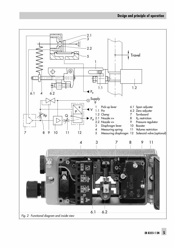
Fig. 2 ⋅ Functional diagram and inside view
7 8 9 10 11 12
6.1 4 6.2
2.13
2.2
5
1
1.1 1.2Pe
Supply 9
V
PstQXp
ep
Travel
4 3 7 8 9 11
6.1 6.2
6.1 Span adjuster6.2 Zero adjuster7 Turnboard8 Xp restriction9 Pressure regulator10 Booster11 Volume restriction12 Solenoid valve (optional)
1 Pick-up lever1.1 Pin1.2 Clamp2.1 Nozzle >>2.2 Nozzle <>3 Diaphragm lever4 Measuring spring5 Measuring diaphragm
EB 8355-1 EN 5
Design and principle of operation
Positioner with position transmitter
A positioner containing a position transmit-ter cannot be equipped with integrated limitswitches or an integrated solenoid valvesince the position transmitter requires mostof the space inside.The position transmitter is used to ensure apreselected relationship between valve posi-tion, i.e. valve travel, and a controller out-put current signal of 4 to 20 mA.The position transmitter setting allows bothvalve end positions “valve CLOSED” or“valve OPEN” as well as all intermediate po-sitions to be indicated. Since the valve posi-tion is always indicated regardless of the po-sitioner’s input signal, the position transmit-ter is a suitable device to check the currentvalve position.
6 EB 8355-1 EN
Design and principle of operation
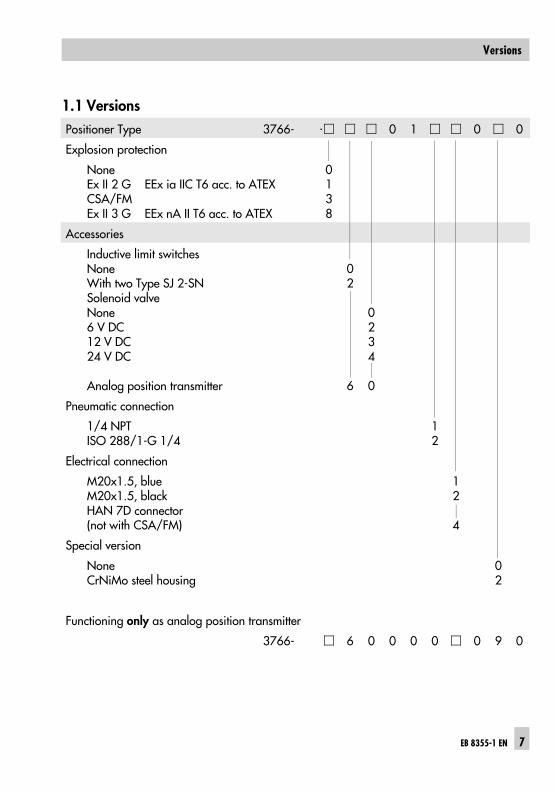
1.1 VersionsPositioner Type 3766- 0 1 0 0
Explosion protection
NoneEx II 2 G EEx ia IIC T6 acc. to ATEXCSA/FMEx II 3 G EEx nA II T6 acc. to ATEX
0138
Accessories
Inductive limit switchesNoneWith two Type SJ 2-SNSolenoid valveNone6 V DC12 V DC24 V DC
Analog position transmitter
02
6
0234
0
Pneumatic connection
1/4 NPTISO 288/1-G 1/4
12
Electrical connection
M20x1.5, blueM20x1.5, blackHAN 7D connector(not with CSA/FM)
12
4
Special version
NoneCrNiMo steel housing
02
Functioning only as analog position transmitter
3766- 6 0 0 0 0 0 9 0
EB 8355-1 EN 7
Versions
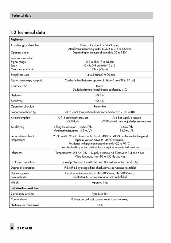
1.2 Technical dataPositioner
Travel range, adjustable
Opening angle
Direct attachment: 7.5 to 30 mm,Attachment according to IEC 60534-6: 7.5 to 120 mm
Depending on the type of cam disk: 30 to 120°
Reference variableSignal rangeSpanMax. overload limit
0.2 to 1bar (3 to 15 psi)0.4 to 0.8 bar (6 to 12 psi)
2 bar (29 psi)
Supply pressure 1.4 to 6 bar (20 to 90 psi)
Signal pressure pst (output) Can be limited between approx. 2.5 to 6.0 bar (38 to 90 psi)
Characteristic LinearDeviation from terminal-based conformity ≤1%
Hysteresis ≤0.3 %
Sensitivity ≤0.1 %
Operating direction Reversible
Proportional band Xp <1 to 2.5 % (proportional-action coefficient Kp: >100 to 40)
Air consumption At 1.4 bar supply pressure≤230 ln/h
At 6 bar supply pressure≤230 ln/h with min. adjusted press. regulator
Air delivery Filling the actuator: 3.0 mn3/h
Venting the actuator: 4.5 mn3/h
8.5 mn3/h
14.0 mn3/h
Permissible ambient temperature
–20 °C to +80 °C with plastic cable gland; –40 °C to +80 °C with metal cable gland(special version down to –45 °C available)
Positioner with position transmitter only –20 to 70 °C, See attached inspection certificates for explosion-protected versions
Influences Temperature: ≤0.3 %/10 K Supply pressure: ≤1 % between 1.4 and 6 barVibration: none from 10 to 150 Hz and 4 g
Explosion protection Type of protection EEx ia IIC T6 (see attached inspection certificate)
Degree of protection IP 54 (IP 65 by using a filter check valve, see Accessories table)
Electromagnetic compatibility
Requirements according to EN 61000-6-2, EN 61000-6-3, and NAMUR Recommendation 21 are fulfilled
Weight Approx. 1 kg
Inductive limit switches
2 proximity switches Type SJ 2-SN
Control circuit Ratings according to downstream transistor relay
Hysteresis at rated travel ≤1 %
8 EB 8355-1 EN
Technical data
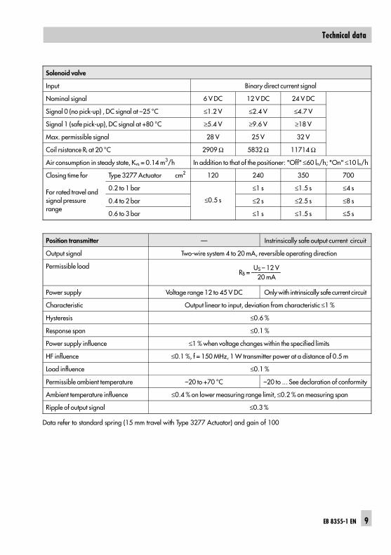
Solenoid valve
Input Binary direct current signal
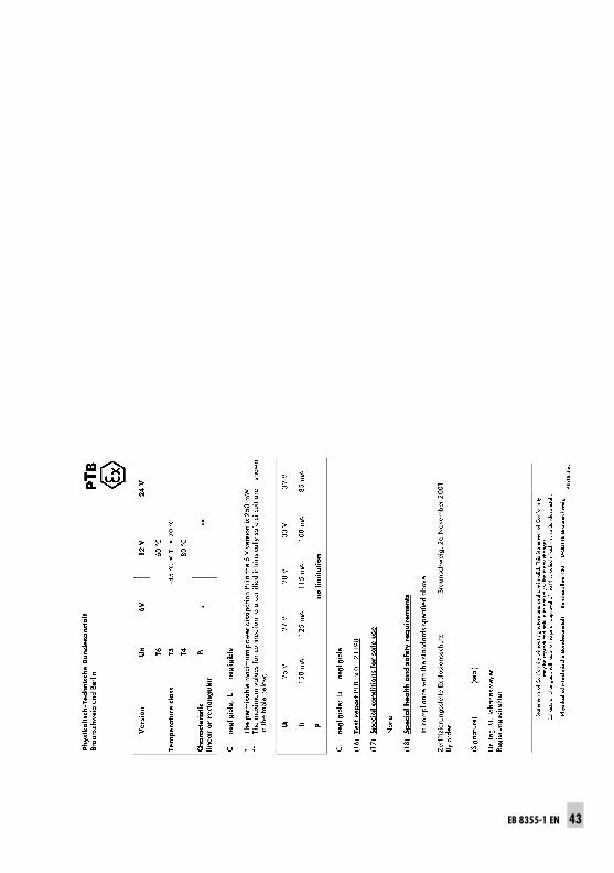
Nominal signal 6 V DC 12 V DC 24 V DC
Signal 0 (no pick-up) , DC signal at –25 °C ≤1.2 V ≤2.4 V ≤4.7 V
Signal 1 (safe pick-up), DC signal at +80 °C ≥5.4 V ≥9.6 V ≥18 V
Max. permissible signal 28 V 25 V 32 V
Coil rsistance Ri at 20 °C 2909 Ω 5832 Ω 11714 Ω
Air consumption in steady state, Kvs = 0.14 m3/h In addition to that of the positioner: "Off" ≤60 ln/h; "On" ≤10 ln/h
Closing time for
For rated travel andsignal pressurerange
Type 3277 Actuator cm2 120 240 350 700
0.2 to 1 bar
≤0.5 s
≤1 s ≤1.5 s ≤4 s
0.4 to 2 bar ≤2 s ≤2.5 s ≤8 s
0.6 to 3 bar ≤1 s ≤1.5 s ≤5 s
Position transmitter — Instrinsically safe output current circuit
Output signal Two-wire system 4 to 20 mA, reversible operating direction
Permissible load US – 12 VRB = –––––––––
20 mA
Power supply Voltage range 12 to 45 V DC Only with intrinsically safe current circuit
Characteristic Output linear to input, deviation from characteristic ≤1 %
Hysteresis ≤0.6 %
Response span ≤0.1 %
Power supply influence ≤1 % when voltage changes within the specified limits
HF influence ≤0.1 %, f = 150 MHz, 1 W transmitter power at a distance of 0.5 m
Load influence ≤0.1 %
Permissible ambient temperature –20 to +70 °C –20 to ... See declaration of conformity
Ambient temperature influence ≤0.4 % on lower measuring range limit, ≤0.2 % on measuring span
Ripple of output signal ≤0.3 %
Data refer to standard spring (15 mm travel with Type 3277 Actuator) and gain of 100
EB 8355-1 EN 9
Technical data
2 Attachment to control valve
The positioner can be attached either di-rectly to a SAMSON Type 3277 Actuatoror to valves with cast yokes or rod-typeyokes according to IEC 60534-6 (NAMUR).When combined with an intermediatepiece, the device can also be attached to ro-tary actuators as a rotary positioner.As the positioner is also available as abasic unit without accessory equipment,refer to the tables on the following pagesfor both the required mounting parts andtheir associated order numbers.Do not remove the protective cover on thepositioner’s rear side before actually start-ing to attach the positioner.
Mounting position and operating direction
The operating direction of the positioneralso determines its mounting position on theactuator as illustrated in Figs. 3, 4, and 6. The turnboard (7, Fig. 2) at the positionermust be mounted correspondingly.For an increasing input signal (referencevariable), the signal pressure pst can eitherbe increasing (direct action >>) or decreas-ing (reverse action <>). This also applies when the reference vari-able decreases: direct action >> causes thesignal pressure to decrease, reverse ac-tion <> causes the signal pressure to in-crease.On the turnboard (7), the operating direc-tion is indicated by symbols (direct >>,reverse <>). Depending on the position of the turnboard,the adjusted operating direction and the as-sociated symbol become visible.
If the required operating direction does notcorrespond to the visible symbol, or if youwant to change the operating direction,remove the fastening screw at the turn-board, turn the board by 180°, and re-fasten the turnboard with the screw. Makesure the three rubber gaskets inserted in thehousing remain in position.
Important!When any subsequent changes are made,e.g. reversing the operating direction of thepositioner control loop or changing the actu-ator from “Actuator stem extends” to “Actu-ator stem retracts” or vice versa, the posi-tioner’s mounting position must be changedaccordingly.
2.1 Direct attachment toType 3277 Actuator
Required accessories are listed in Tables 1to 4 on page 14.
The attachment of the positioner either onthe left or right side of the actuator (alwayslooking at the signal pressure connection orswitchover plate) is determined by the re-quired operating direction of the positioner,i.e. >> or <>.
10 EB 8355-1 EN
Attachment to control valve
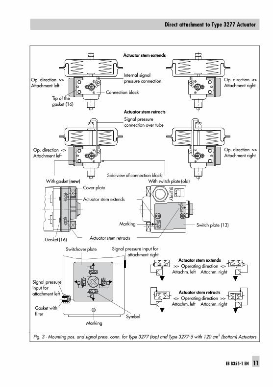
Fig. 3 ⋅ Mounting pos. and signal press. conn. for Type 3277 (top) and Type 3277-5 with 120 cm2 (bottom) Actuators
SUPPLY
Actuator stem extends
Actuator stem retracts
Signal pressureinput for attachment left
Gasket with filter
Signal pressure input for attachment right
Actuator stem extends>> Operating direction <>
Attachm. left Attachm. right
Actuator stem retracts<> Operating direction >>
Attachm. left Attachm. right
Internal signal pressure connection Op. direction <>
Attachment rightOp. direction >>Attachment left
Actuator stem extends
Op. direction <>Attachment left
Marking
Marking
Actuator stem retracts
Op. direction >>Attachment right
Symbol
Signal pressure connection over tube
Side view of connection block With gasket (new) With switch plate (old)
Connection block Tip of thegasket (16)
Cover plate
Switch plate (13)
Switchover plate
Gasket (16)
EB 8355-1 EN 11
Direct attachment to Type 3277 Actuator
1. Screw the clamp (1.2) to the actuatorstem. Make sure that the fasteningscrew is located in the groove of the ac-tuator stem.
2. Screw the associated lever D1 or D2(for 700 cm2 actuator) to the pick-uplever of the positioner.
3. Fasten the distance plate (15) with theseal pointing towards the actuator yoke.
4. Attach the positioner such that the leverD1 or D2 slides centrically over thepin (1.1) of the clamp (1.2). Screw thepositioner to the distance plate (15).
5. Mount the cover (16).6. Check whether the correct measuring
spring has been installed as listed inTable 4. Measuring spring 1 is installedby default. If necessary, replace it withspring 2 included in the accessoriesand fix it at the outer slot.
240, 350, and 700 cm2 actuators
7. Make sure that the tip of the gasket (16)projecting from the side of the connec-tion block (Fig. 3, middle) is positionedto match the actuator symbol that corre-sponds to the actuator’s fail-safe action"Actuator stem extends" or "Actuatorstem retracts".If this is not the case, remove the threefixing screws and the cover. Repositionthe gasket (16) turned by 180°. The old connection block version re-quires the switch plate (13) to be turnedsuch that the corresponding actuatorsymbol points to the marking.
8. Place the connection block with its seal-ing rings on the positioner and the actu-
ator yoke and screw tight using thefastening screw. Actuators with “Actua-tor stem retracts” require the ready-made signal pressure line to be in-stalled.
120 cm2 actuators
The signal pressure is transmitted to the dia-phragm chamber over the switchover plate(Figs. 3 and 4, bottom). 7. Remove the screw in the rear cover of
the positioner (Fig. 5) and seal the lat-eral signal pressure output “output”with the plug contained in the acces-sories kit.
8. Mount the positioner such that the borein the distance plate (15) mates with theseal in the bore of the actuator yoke.
9. Align the switchover plate with thecorresponding symbol and fasten it tothe actuator yoke.
Important! When a solenoid valve or a similar deviceis attached to the 120 cm2 actuator in addi-tion to the positioner, do not remove therear M3 screw plug. In this case, the signalpressure must be transmitted from the signalpressure output to the actuator over an addi-tional connecting plate (Table 2). The swit-chover plate (Figs. 3 and 4) is not used.
Filling the actuator with air
If the spring chamber of the actuator mustbe filled with the positioner’s exhaust air,use a tube (Table 3) to connect the springchamber (with version “Actuator stem ex-tends”) to the connection block. To do so,
12 EB 8355-1 EN
Direct attachment to Type 3277 Actuator
remove the plug from the connection block.For version “Actuator stem retracts” andType 3277-5 Actuators with an effective dia-phragm area of 120 cm2, an internal borehole ensures that the spring chamber isfilled with air.
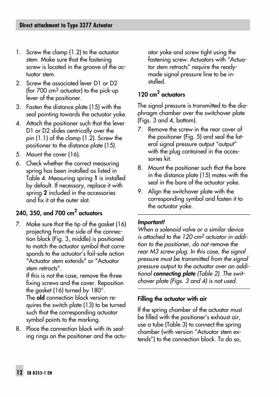
Important! When the valve is installed, the lateral coverof the actuator must be mounted such thatthe vent plug points downward.
Fig. 4 ⋅ Mounting the clamp
1.2
D2
D1
15Vent plug
Attachment left Attachment rightLooking onto the signal pressure connection
Signal pressure bore
Switchover plate
Cover
Type 3277-5with 120 cm2
Vent plug must pointdownward when valveis installedDistance plate (15)
Clamp (1.2)
Type 3277with 240, 350,and 700 cm2
EB 8355-1 EN 13
Direct attachment to Type 3277 Actuator
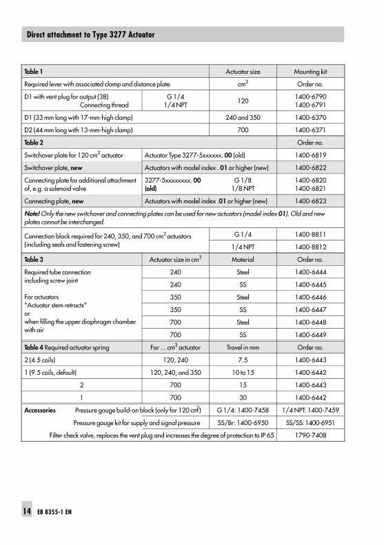
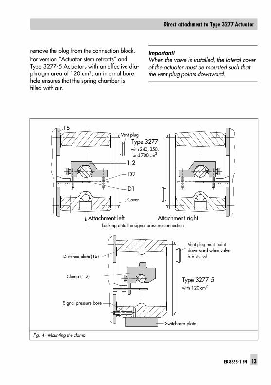
Table 1 Actuator size Mounting kit
Required lever with associated clamp and distance plate cm2 Order no.
D1 with vent plug for output (38) Connecting thread
G 1/41/4 NPT
1201400-67901400-6791
D1 (33 mm long with 17-mm-high clamp) 240 and 350 1400-6370
D2 (44 mm long with 13-mm-high clamp) 700 1400-6371
Table 2 Order no.
Switchover plate for 120 cm2 actuator Actuator Type 3277-5xxxxxx. 00 (old) 1400-6819
Switchover plate, new Actuators with model index . 01 or higher (new) 1400-6822
Connecting plate for additional attachmentof, e.g. a solenoid valve
3277-5xxxxxxxx. 00(old)
G 1/81/8 NPT
1400-68201400-6821
Connecting plate, new Actuators with model index .01 or higher (new) 1400-6823
Note! Only the new switchover and connecting plates can be used for new actuators (model index 01). Old and newplates cannot be interchanged.
Connection block required for 240, 350, and 700 cm2 actuators(including seals and fastening screw)
G 1/4 1400-8811
1/4 NPT 1400-8812
Table 3 Actuator size in cm2 Material Order no.
Required tube connection including screw joint
For actuators"Actuator stem retracts" or when filling the upper diaphragm chamberwith air
240 Steel 1400-6444
240 SS 1400-6445
350 Steel 1400-6446
350 SS 1400-6447
700 Steel 1400-6448
700 SS 1400-6449
Table 4 Required actuator spring For ... cm2 actuator Travel in mm Order no.
2 (4.5 coils) 120, 240 7.5 1400-6443
1 (9.5 coils, default) 120, 240, and 350 10 to 15 1400-6442
2 700 15 1400-6443
1 700 30 1400-6442
Accessories Pressure gauge build-on block (only for 120 cm2) G 1/4: 1400-7458 1/4 NPT: 1400-7459
Pressure gauge kit for supply and signal pressure SS/Br: 1400-6950 SS/SS: 1400-6951
Filter check valve, replaces the vent plug and increases the degree of protection to IP 65 1790-7408
14 EB 8355-1 EN
Direct attachment to Type 3277 Actuator
2.2 Attachment according toIEC 60534-6
Required mounting parts are listed inTable 5. The rated travel of the valve deter-mines which lever and measuring spring(Table 6) are required.
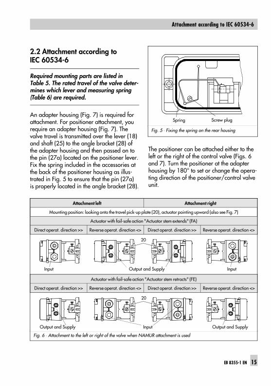
An adapter housing (Fig. 7) is required forattachment. For positioner attachment, yourequire an adapter housing (Fig. 7). Thevalve travel is transmitted over the lever (18)and shaft (25) to the angle bracket (28) ofthe adapter housing and then passed on tothe pin (27a) located on the positioner lever.Fix the spring included in the accessories atthe back of the positioner housing as illus-trated in Fig. 5 to ensure that the pin (27a)is properly located in the angle bracket (28).
The positioner can be attached either to theleft or the right of the control valve (Figs. 6and 7). Turn the positioner at the adapterhousing by 180° to set or change the opera-ting direction of the positioner/control valveunit.
Fig. 5 ⋅ Fixing the spring on the rear housing
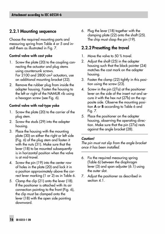
Fig. 6 ⋅ Attachment to the left or right of the valve when NAMUR attachment is used
Actuator with fail-safe action "Actuator stem retracts" (FE)
Direct operat. direction >> Reverse operat. direction <> Direct operat. direction >> Reverse operat. direction <>
Attachment left Attachment right
Mounting position: looking onto the travel pick-up plate (20), actuator pointing upward (also see Fig. 7)
Actuator with fail-safe action "Actuator stem extends" (FA)
Direct operat. direction >> Reverse operat. direction <> Direct operat. direction >> Reverse operat. direction <>
Spring Screw plug
20
Input Output and Supply Input
20
Output and Supply Input Output and Supply
EB 8355-1 EN 15
Attachment according to IEC 60534-6
2.2.1 Mounting sequence
Choose the required mounting parts andmeasuring spring from Table 4 or 5 and in-stall them as illustrated in Fig. 7.
Control valve with cast yoke
1. Screw the plate (20) to the coupling con-necting the actuator and plug stemsusing countersunk screws. For 2100 and 2800 cm2 actuators, usean additional mounting bracket (32).
2. Remove the rubber plug from inside theadapter housing. Fasten the housing tothe left or right of the NAMUR rib usinga hexagon screw (see Fig. 6).
Control valve with rod-type yoke
1. Screw the plate (20) to the carrier of theplug stem.
2. Screw the studs (29) into the adapterhousing.
3. Place the housing with the mountingplate (30) on either the right or left side(Fig. 6) of the plug stem and fasten itwith the nuts (31). Make sure that thelever (18) to be mounted subsequentlyis in horizontal position when the valveis at mid-travel.
4. Screw the pin (19) into the center rowof holes in the plate (20) and lock it ina position approximately above the cor-rect lever marking (1 or 2) as in Table 6.
5. Clamp the clip (21) onto the lever (18).If the positioner is attached with its airconnection pointing to the front (Fig. 6),the clip must be clamped onto thelever (18) with the open side pointingdownward.
6. Plug the lever (18) together with theclamping plate (22) onto the shaft (25).The chip must clasp the pin (19).
2.2.2 Presetting the travel
1. Move the valve to 50 % travel. 2. Adjust the shaft (25) in the adapter
housing such that the black pointer (24)matches the cast mark on the adapterhousing.
3. Fasten the clamp (22) tightly in this posi-tion using the screw (23).
4. Screw in the pin (27a) at the positionerlever on the side of the insert nut and se-cure it with the hex nut (27b) on the op-posite side. Observe the mounting posi-tion A or B according to Table 6 andFig. 7.
5. Place the positioner on the adapterhousing, observing the operating direc-tion. Make sure that the pin (27a) restsagainst the angle bracket (28).
Caution!The pin must not slip from the angle bracketonce it has been installed.
6. Fix the required measuring spring(Table 6) between the diaphragmlever (3) and span adjuster (6.1) usingthe outer slot.
7. Adjust the positioner as described insection 4.1.
16 EB 8355-1 EN
Attachment according to IEC 60534-6
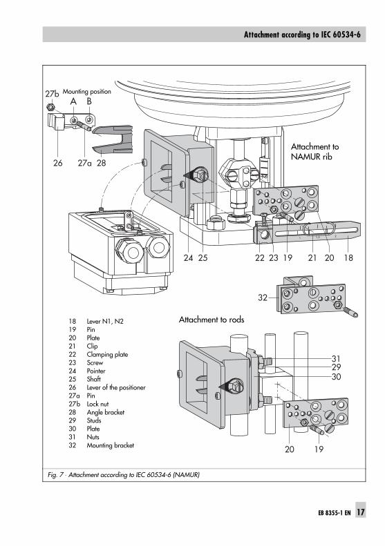
Fig. 7 ⋅ Attachment according to IEC 60534-6 (NAMUR)
21,51
24 25 22
32
31
20 19
19 21 2023 18
2930
2826
A B27b
27a
Attachment to NAMUR rib
Mounting position
Attachment to rods18 Lever N1, N219 Pin20 Plate21 Clip22 Clamping plate23 Screw24 Pointer25 Shaft26 Lever of the positioner27a Pin27b Lock nut28 Angle bracket29 Studs30 Plate31 Nuts32 Mounting bracket
EB 8355-1 EN 17
Attachment according to IEC 60534-6
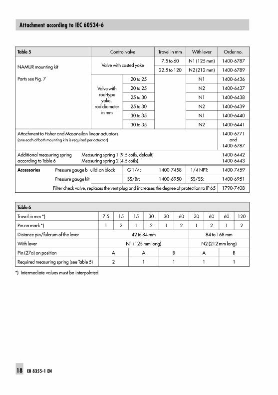
Table 5 Control valve Travel in mm With lever Order no.
NAMUR mounting kit
Parts see Fig. 7
Valve with casted yoke7.5 to 60 N1 (125 mm) 1400-6787
22.5 to 120 N2 (212 mm) 1400-6789
Valve withrod-typeyoke,
rod diameterin mm
20 to 25 N1 1400-6436
20 to 25 N2 1400-6437
25 to 30 N1 1400-6438
25 to 30 N2 1400-6439
30 to 35 N1 1400-6440
30 to 35 N2 1400-6441
Attachment to Fisher and Masoneilan linear actuators(one each of both mounting kits is required per actuator)
1400-6771and
1400-6787
Additional measuring spring Measuring spring 1 (9.5 coils, default)according to Table 6 Measuring spring 2 (4.5 coils)
1400-64421400-6443
Accessories Pressure gauge b uild-on block G 1/4: 1400-7458 1/4 NPT: 1400-7459
Pressure gauge kit SS/Br: 1400-6950 SS/SS: 1400-6951
Filter check valve, replaces the vent plug and increases the degree of protection to IP 65 1790-7408
Table 6
Travel in mm *) 7.5 15 15 30 30 60 30 60 60 120
Pin on mark *) 1 2 1 2 1 2 1 2 1 2
Distance pin/fulcrum of the lever 42 to 84 mm 84 to 168 mm
With lever N1 (125 mm long) N2 (212 mm long)
Pin (27a) on position A A B A B
Required measuring spring (see Table 5) 2 1 1 1 1
*) Intermediate values must be interpolated
18 EB 8355-1 EN
Attachment according to IEC 60534-6
2.3 Attachment to rotary actuators
The positioner can also be attached to rota-ry actuators according to VDI/VDE 3845when the mounting kits and accessorieslisted in Table 7 are used. The rotary mo-tion of these actuators is converted into a li-near motion required by the pneumatic con-trol unit of the positioner using the cam diskof the actuator shaft and a cam follower rollon the positioner lever.
Important!Use Table 7 to check whether the propermeasuring spring (1 or 2) has been in-stalled. Measuring spring 1 is installed bydefault. Measuring spring 2 is contained inthe mounting parts.
Double-acting springless actuators requirethe use of a reversing amplifier on the con-nection side of the positioner housing (seesection 2.3.4).
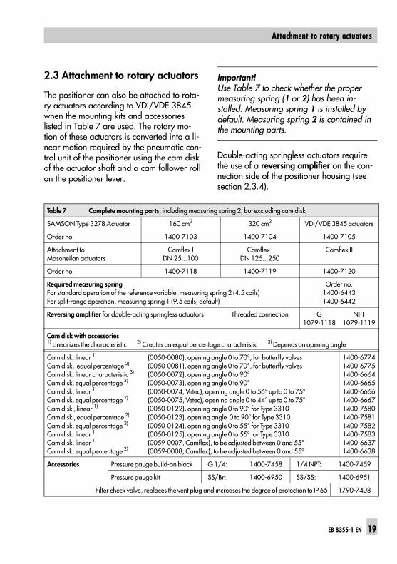
Table 7 Complete mounting parts, including measuring spring 2, but excluding cam disk
SAMSON Type 3278 Actuator 160 cm2 320 cm2 VDI/VDE 3845 actuators
Order no. 1400-7103 1400-7104 1400-7105
Attachment to Masoneilan actuators
Camflex IDN 25...100
Camflex IDN 125...250
Camflex II
Order no. 1400-7118 1400-7119 1400-7120
Required measuring springFor standard operation of the reference variable, measuring spring 2 (4.5 coils)For split-range operation, measuring spring 1 (9.5 coils, default)
Order no.1400-64431400-6442
Reversing amplifier for double-acting springless actuators Threaded connection G1079-1118
NPT1079-1119
Cam disk with accessories1) Linearizes the characteristic 2) Creates an equal percentage characteristic 3) Depends on opening angle
Cam disk, linear 1) (0050-0080), opening angle 0 to 70°, for butterfly valvesCam disk, equal percentage 2) (0050-0081), opening angle 0 to 70°, for butterfly valvesCam disk, linear characteristic 3) (0050-0072), opening angle 0 to 90°Cam disk, equal percentage 3) (0050-0073), opening angle 0 to 90°Cam disk, linear 1) (0050-0074, Vetec), opening angle 0 to 56° up to 0 to 75°Cam disk, equal percentage 2) (0050-0075, Vetec), opening angle 0 to 44° up to 0 to 75°Cam disk , linear 1) (0050-0122), opening angle 0 to 90° for Type 3310Cam disk , equal percentage 2) (0050-0123), opening angle 0 to 90° for Type 3310Cam disk, equal percentage 2) (0050-0124), opening angle 0 to 55° for Type 3310Cam disk, linear 1) (0050-0125), opening angle 0 to 55° for Type 3310 Cam disk, linear 1) (0059-0007, Camflex), to be adjusted between 0 and 55°Cam disk, equal percentage 2) (0059-0008, Camflex), to be adjusted between 0 and 55°
1400-67741400-67751400-66641400-66651400-66661400-66671400-75801400-75811400-75821400-75831400-66371400-6638
Accessories Pressure gauge build-on block G 1/4: 1400-7458 1/4 NPT: 1400-7459
Pressure gauge kit SS/Br: 1400-6950 SS/SS: 1400-6951
Filter check valve, replaces the vent plug and increases the degree of protection to IP 65 1790-7408
EB 8355-1 EN 19
Attachment to rotary actuators
When using a reversing amplifier, the press-ure regulator (9, Fig. 2) must be turnedclockwise as far as it will go (also see sec-tion 3.1.2).When attaching the positioner to the SAM-SON Type 3278 Rotary Actuator (Fig. 8,left), the actuator’s inside and the unusedreverse side of the diaphragm are filledwith the positioner’s exhaust air. Additionalpiping is not required.When attaching the positioner to other actu-ator makes (Fig. 8, right), the reverse sideof the diaphragm can be filled with air overa tube connection installed between the ac-tuator and the intermediate piece.
2.3.1 Mounting the cam followerlever
1. Place the lever with cam followerroll (35) on the side of the feedbacklever (37) opposite the insert nuts.Fasten with the supplied screws (38)and washers.
Important!To ensure a close physical contact betweenthe cam follower roll and the cam disk, fixthe spring contained in the accessories kit(order no. 1400-6660) at the rear of the po-sitioner housing (see Fig. 5)
2.3.2 Mounting the intermediatepiece
SAMSON Type 3278 Actuator
1. Screw the adapter (36) to the free endof the actuator shaft.
2. Attach the intermediate piece (34) tothe actuator housing using two screwseach. Align the intermediate piece to ensurethat the air connections of the posi-tioner point towards the diaphragmhousing.
3. Align the cam disk (40) and scale (39)as described in section 2.3.3 and fastenwith screws.
Actuators according to VDI/VDE 3845(fixing level 1)1. Place the complete intermediate piece
(34, 44, 45, and 42) onto the mountingbracket (43) that came with the actuatorand fasten with two screws.
2. Align the cam disk (40) and scale (39)as described in section 2.3.3 and fastenwith screws.
20 EB 8355-1 EN
Attachment to rotary actuators
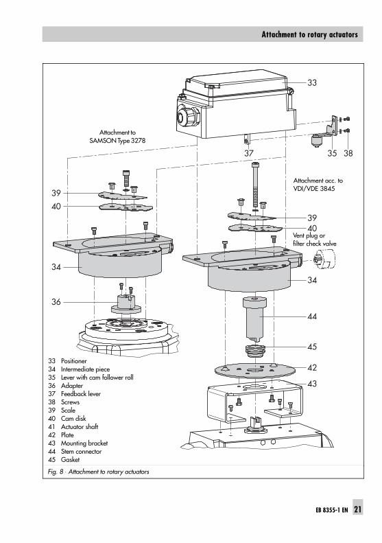
Fig. 8 ⋅ Attachment to rotary actuators
33
3835
39
39
40
34
36
40
34
44
45
42
43
37
Vent plug or filter check valve
Attachment acc. toVDI/VDE 3845
Attachment toSAMSON Type 3278
33 Positioner34 Intermediate piece35 Lever with cam follower roll36 Adapter37 Feedback lever38 Screws39 Scale40 Cam disk41 Actuator shaft42 Plate43 Mounting bracket44 Stem connector45 Gasket
EB 8355-1 EN 21
Attachment to rotary actuators
2.3.3 Default setting of the camdisk
The valve model used determines the defaultsetting of the cam disk.
Important!Cam disks tailored to the special charac-teristic of a valve cause the valve to open ina non-linear or non-equal percentage way.The visible difference between the set point(4 to 20 mA) and the actual value (openingangle) does not constitute a system devia-tion of the positioner.
Figs. 9 and 10 show linear cam disks. Fig. 9 illustrates a control valve assemblywith a spring-loaded rotary actuator thatopens counterclockwise. The arrangementof the springs in the actuator determines thefail-safe position of the valve.Fig. 10 shows how to adjust the cam diskwhen a double-acting springless rotary actu-ator is used. The direction of rotation, eithercounterclockwise or clockwise, depends onthe actuator and valve model used. The camdisk must be set when the valve is closed.Use the turnboard (7) to adjust the opera-ting direction of the positioner, i.e. whetherthe valve opens or closes when the refer-ence variable increases (direct >> orreverse <>).Each cam disk carries two cam sectionswhose starting points are indicated by smallbores. Depending on the operating direc-tion of the rotary actuator—signal pressureopens or closes the valve—the starting pointof the cam, either marked N (standard char-acteristic) or I (reverse characteristic), must
point towards the cam follower roll. Whenthe starting point is located on the back ofthe cam disk, turn over the cam disk.
Important!The starting point (bore) of the selected camsection must be aligned with the fulcrum ofthe cam disk, the 0° position of the scale,and the arrow symbol on the inspectionglass.
When aligning the cam disk, the double-sided scale disk must be clipped on the camdisk such that the value on the scale corre-sponds to the control valve’s direction of ro-tation (see Fig. 9, top left).
Important!Make sure the 0° position of the scale al-ways corresponds to closed position. For actuators with fail-safe position "valveOPEN" and for springless actuators, it istherefore necessary to apply the maximumsupply pressure to the actuator before alig-ning the cam disk.
22 EB 8355-1 EN
Attachment to rotary actuators
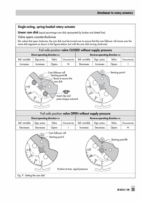
Single-acting, spring-loaded rotary actuator
Linear cam disk (equal percentage cam disk represented by broken and dotted line)
Valve opens counterclockwise(for valves that open clockwise, the cam disk must be turned over to ensure that the cam follower roll moves over thesame disk segments as shown in the figures below, but with the cam disk turning clockwise)
Fig. 9 ⋅ Setting the cam disk
Fail-safe position valve CLOSED without supply pressureDirect operating direction >> Reverse operating direction <>
Ref. variable Sign press. Valve Characteristic Ref. variable Sign. press. Valve Characteristic
Increases Increases Opens N Decreases Increases Opens I
Fail-safe position valve OPEN without supply pressureDirect operating direction >> Reverse operating direction <>
Ref. variable Sign. press. Valve Characteristic Ref. variable Sign. press. Valve Characteristic
Decreases Decreases Opens I Increases Decreases Opens N
90˚60˚
30˚ 0˚
90˚60˚
30˚ 0˚
Cam follower roll Starting point IStarting point N
Bores to secure the cam disk
Insert clip and press tongue outward
90˚60˚
30˚ 0˚
90˚60˚
30˚ 0˚
Starting point I
Cam follower roll
Starting point N
Position at max. signal pressure
EB 8355-1 EN 23
Attachment to rotary actuators
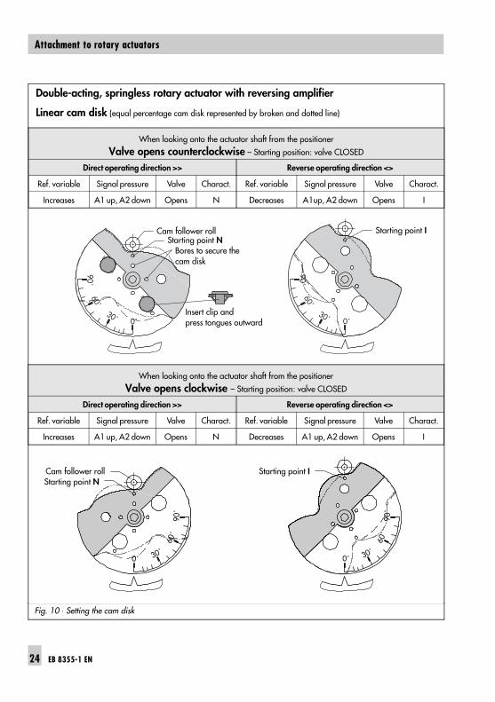
Double-acting, springless rotary actuator with reversing amplifier
Linear cam disk (equal percentage cam disk represented by broken and dotted line)
Fig. 10 ⋅ Setting the cam disk
When looking onto the actuator shaft from the positioner
Valve opens counterclockwise – Starting position: valve CLOSED
Direct operating direction >> Reverse operating direction <>
Ref. variable Signal pressure Valve Charact. Ref. variable Signal pressure Valve Charact.
Increases A1 up, A2 down Opens N Decreases A1up, A2 down Opens I
When looking onto the actuator shaft from the positioner
Valve opens clockwise – Starting position: valve CLOSED
Direct operating direction >> Reverse operating direction <>
Ref. variable Signal pressure Valve Charact. Ref. variable Signal pressure Valve Charact.
Increases A1 up, A2 down Opens N Decreases A1 up, A2 down Opens I
90˚60˚
30˚ 0˚
90˚60˚
30˚ 0˚
Starting point NCam follower roll Starting point I
Bores to secure thecam disk
Insert clip and press tongues outward
0˚
90˚
60˚
30˚0˚
90˚
60˚
30˚
Starting point NCam follower roll Starting point I
24 EB 8355-1 EN
Attachment to rotary actuators
Securing the aligned cam disk
To additionally prevent the cam disk frombeing turned, drill a bore into the adapt-er (36) or the stem connector (44) and in-stall a 2 mm dowel pin. Four bore holes are located centricallyaround the center bore hole on the camdisk. Select a suitable hole to install the pin.
EB 8355-1 EN 25
Attachment to rotary actuators
2.3.4 Reversing amplifier fordouble-acting actuators
When used with double-acting actuators,the positioner must be equipped with a re-versing amplifier. The reversing amplifier is listed as an acces-sory in Table 7 on page 19.The output signal pressure of the positioneris supplied at output A1 of the reversing am-plifier. An opposing pressure, which equalsthe required supply pressure when added tothe pressure at A1, is supplied at output A2.A1 + A2 = Z applies.
Assembly
Important! Remove the sealing plug (1.5) before install-ing the reversing amplifier. The rubberseal (1.4) must remain installed.
1. Screw the special nuts (1.3) included inthe accessories of the reversing ampli-fier into the threaded connections of thepositioner.
2. Insert the gasket (1.2) into the recess ofthe reversing amplifier and push thetwo hollowed special screws (1.1) intothe connecting bore holes A1 and Z.
3. Place the reversing amplifier onto thepositioner and screw tight using the twospecial screws (1.1).
Signal pressure connections
A1: Connect output A1 to the signal press-ure connection on the actuator that opensthe valve when the pressure increases.A2 : Connect output A2 to the signal press-ure connection on the actuator that closesthe valve when the pressure increases.
26 EB 8355-1 EN
Reversing amplifier for double-acting actuators
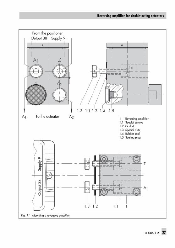
Fig. 11 ⋅ Mounting a reversing amplifier
A1
1.5
1.3 1.2 1.1
1.3 1.21.1
1
Z
A2
1.4A1 A2
Z
A1
Output 38 Supply 9O
utpu
t 38
Supp
ly 9
1 Reversing amplifier1.1 Special screws1.2 Gasket1.3 Special nuts1.4 Rubber seal1.5 Sealing plug
From the positioner
To the actuator
EB 8355-1 EN 27
Reversing amplifier for double-acting actuators
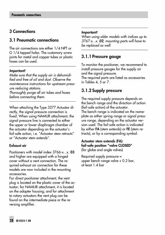
3 Connections
3.1 Pneumatic connections
The air connections are either 1/4 NPT orG 1/4 tapped holes. The customary screwjoints for metal and copper tubes or plastichoses can be used.
Important!Make sure that the supply air is dehumidi-fied and free of oil and dust. Observe themaintenance instructions for upstream press-ure reducing stations. Thoroughly purge all air tubes and hosesbefore connecting them.
When attaching the Type 3277 Actuator di-rectly, the signal pressure connection isfixed. When using NAMUR attachment, thesignal pressure line is connected to eitherthe upper or lower diaphragm chamber ofthe actuator depending on the actuator’sfail-safe action, i.e. “Actuator stem retracts”or ”Actuator stem extends”.
Exhaust air
Positioners with model index 3766-x...x. 03and higher are equipped with a hingedcover without a vent connection. The re-quired exhaust air connection for thesemodels are now included in the mountingaccessories.For direct positioner attachment, the ventplug is located on the plastic cover of the ac-tuator; for NAMUR attachment, it is locatedon the adapter housing; and for attachmentto rotary actuators the vent plug can befound on the intermediate piece or the re-versing amplifier.
Important! When using older models with indices up to3767-x...x. 02, mounting parts will have tobe replaced as well.
3.1.1 Pressure gauge
To monitor the positioner, we recommend toinstall pressure gauges for the supply airand the signal pressure. The required parts are listed as accessoriesin Tables 4, 5 or 7.
3.1.2 Supply pressure
The required supply pressure depends onthe bench range and the direction of action(fail-safe action) of the actuator.The bench range is indicated on the name-plate as either spring range or signal press-ure range, depending on the actuator ver-sion used. The fail-safe action is indicatedby either FA (stem extends) or FE (stem re-tracts), or by a corresponding symbol.
Actuator stem extends (FA):fail-safe position "valve CLOSED"(for globe and angle valves)
Required supply pressure = upper bench range valve + 0.2 bar, at least 1.4 bar
28 EB 8355-1 EN
Pneumatic connections
Actuator stem retracts (FE):fail-safe position"valve OPEN"(for globe and angle valves)
The required supply pressure for a tight-clos-ing valve is roughly calculated as followsusing the maximum signal pressure pstmax:
pstmax = F + d2 ⋅ π ⋅ ∆p
4 ⋅ A [bar]
d = Seat diameter [cm]∆p = Pressure drop across the valve [bar]A = Actuator area [cm2]F = Upper bench range value of the actuator
In case this information is not available,proceed as follows:
Required supply pressure = upper bench range value + 1 bar
Pressure regulator
After tilting the cover plate back, the press-ure regulator (9) can be continuously ad-justed. When the adjuster is turned counter-clockwise as far as it will go, signal press-ures for spring ranges up to 2.5 bar arecontrolled. When the adjuster is turnedclockwise all the way, signal pressures forspring ranges up to 6.0 bar are controlled. If the signal pressure must not exceed a cer-tain value, this limit can be adjusted using apressure gauge (accessories).
3.2 Electrical connections
For electrical installation, you are re-quired to observe the relevant elec-trotechnical regulations and the acci-dent prevention regulations thatapply in the country of use. In Ger-many, these are the VDE regulationsand the accident prevention regula-tions of the employers’ liability insur-ance.The following regulations apply forinstallation in hazardous areas:EN 60079-14: 1997; VDE 0165Part 1/8.98 "Electrical apparatusfor explosive gas atmospheres" andEN 50281-1-2: VDE 0165Part 2/11.99 "Electrical apparatusfor use in the presence of combus-tible dust". For intrinsically safe elec-trical equipment approved in accord-ance with directive 79/196/EEC,the data specified in the certificateof conformity apply for the connec-tion of intrinsically safe circuits.For intrinsically safe electrical equip-ment approved in accordance withdirective 94/9/EC, the data speci-fied in the EC Type Examination Cer-tificate apply for the connection ofintrinsically safe circuits.Caution! The terminal assignmentspecified in the certificate must beadhered to. Switching the assign-ment of the electrical terminals maycause the explosion protection tobecome ineffective!Do not loosen enameled screws inor on the housing.
EB 8355-1 EN 29
Electrical connections
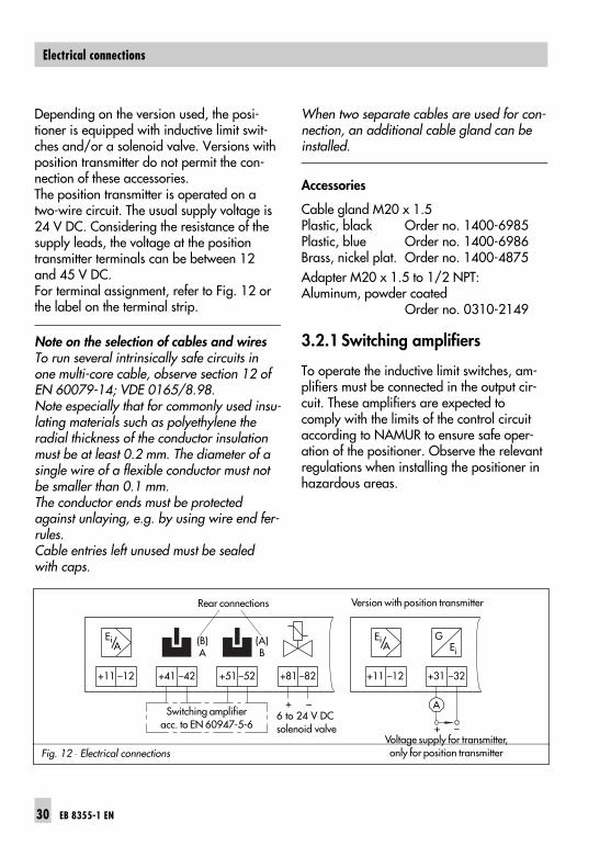
Depending on the version used, the posi-tioner is equipped with inductive limit swit-ches and/or a solenoid valve. Versions withposition transmitter do not permit the con-nection of these accessories. The position transmitter is operated on atwo-wire circuit. The usual supply voltage is24 V DC. Considering the resistance of thesupply leads, the voltage at the positiontransmitter terminals can be between 12and 45 V DC.For terminal assignment, refer to Fig. 12 orthe label on the terminal strip.
Note on the selection of cables and wires To run several intrinsically safe circuits inone multi-core cable, observe section 12 ofEN 60079-14; VDE 0165/8.98. Note especially that for commonly used insu-lating materials such as polyethylene theradial thickness of the conductor insulationmust be at least 0.2 mm. The diameter of asingle wire of a flexible conductor must notbe smaller than 0.1 mm.The conductor ends must be protectedagainst unlaying, e.g. by using wire end fer-rules. Cable entries left unused must be sealedwith caps.
When two separate cables are used for con-nection, an additional cable gland can beinstalled.
Accessories
Cable gland M20 x 1.5Plastic, black Order no. 1400-6985Plastic, blue Order no. 1400-6986Brass, nickel plat. Order no. 1400-4875Adapter M20 x 1.5 to 1/2 NPT:Aluminum, powder coated
Order no. 0310-2149
3.2.1 Switching amplifiers
To operate the inductive limit switches, am-plifiers must be connected in the output cir-cuit. These amplifiers are expected tocomply with the limits of the control circuitaccording to NAMUR to ensure safe oper-ation of the positioner. Observe the relevantregulations when installing the positioner inhazardous areas.
Fig. 12 ⋅ Electrical connections
+41 –42 +51 –52 +81 –82 +31 –32
GEi
+ –
+ –
(B)A
(A)B
A
+11 –12 +11 –12
Ei/Ei/ AA
Rear connections Version with position transmitter
Switching amplifieracc. to EN 60947-5-6
Voltage supply for transmitter,only for position transmitter
6 to 24 V DCsolenoid valve
30 EB 8355-1 EN
Electrical connections
4 Operation
4.1 Adjusting the positioner at thevalve
Starting point and reference variable
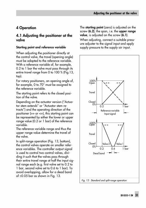
When adjusting the positioner directly atthe control valve, the travel (opening angle)must be adapted to the reference variable. With a reference variable of, for example,0.2 to 1 bar the valve must pass through itsentire travel range from 0 to 100 % (Fig.13,top).For rotary positioners, an opening angle of,for example, 0 to 70° must be assigned tothe reference variable.The starting point refers to the closed posi-tion of the valve.Depending on the actuator version (“Actua-tor stem extends” or “Actuator stem re-tracts”) and the operating direction of thepositioner (>> or <>), this starting point canbe represented by either the lower or upperrange value (0.2 or 1 bar) of the referencevariable.The reference variable range and thus theupper range value determine the travel ofthe valve.In split-range operation (Fig. 13, bottom),the control valves operate on smaller refer-ence variables. The controller output signalis used to control two control valves, divi-ding it such that the valves pass throughtheir entire travel range at half the input sig-nal range each (e.g. first valve set to 0.2 to1 bar, second valve set to 0.6 to 1 bar). Toavoid overlapping, allow for a dead bandof ±0.05 bar as shown in Fig. 13.
The starting point (zero) is adjusted on thescrew (6.2); the span, i.e. the upper rangevalue, is adjusted on the screw (6.1).When adjusting, connect a suitable press-ure adjuster to the signal input and applysupply pressure to the supply air input.
Fig. 13 ⋅ Standard and split-range operation
100%
0%
0.2 1 bar0.6
0.2 1 bar
100%
0%
< > < <
< > < <
Reference variableInput signal
Dead band
Open
Travel
Closed
Open
Travel
Closed Valve 2 Valve 1
EB 8355-1 EN 31
Adjusting the positioner at the valve
4.1.1 Adjusting the proportionalband Xp and air delivery Q
1. Close the volume restriction Q (11) asfar as the required positioning speedpermits. To check, push the diaphragmlever (3) as far as it will go.
2. Adjust the reference variable at theinput to approx. 50 % of its range.
3. Turn the zero adjuster (6.2) until thevalve has reached approx. mid-travel.
4. Use the adjuster (8) to set the propor-tional band Xp to a medium value(1/2 turn).
5. Check the valve’s tendency to hunt andthe positioning speed by briefly tappingthe diaphragm lever (3). The Xp value isto be adjusted to be as small aspossible, yet avoiding that considerableovershooting occurs.
Important!Always adjust the Xp restriction before set-ting the starting point. Later modificationscause the zero point to shift.
4.1.2 Adjusting the actuator: "Actu-ator stem extends"
Important!To ensure that the valve can be closed withfull force, fully vent the diaphragm chamberwhen the reference variable reaches itslower (operating direction <<) and upper(operating direction <>) value.As a result, adjust the input signal to aslightly increased starting point of 0.23 barfor direct operating direction <<; for reverseoperating direction <>, adjust the input sig-nal to a slightly reduced starting point of0.97 bar.
Starting point (e.g. 0.23 bar)
1. Use the pressure adjuster to set theinput signal to 0.2 bar.
2. Turn the zero adjuster (6.2) until thevalve just starts to move from its initialposition.
3. Shut off the input signal and slowly in-crease it again. Check whether thevalve start to move at exactly 0.23 bar. Correct any deviation on the zero adjus-ter (6.2).
Upper range value (e.g. 1 bar)
1. Once the starting point has been set, in-crease the input signal to 1 bar usingthe pressure adjuster. At exactly 1 bar,the plug stem must stand still, havingpassed through 100 % travel (watch thetravel indicator at the valve). If the upper range value is incorrect,turn the span adjuster (travel). Fourturns correspond to a travel change of10 % in standard operation.
32 EB 8355-1 EN
Adjusting the positioner at the valve
In split-range operation, this value is re-duced by half.Turn the adjuster clockwise to reducethe travel and counterclockwise to in-crease it.
2. After correction has been completed,shut off the input signal and slowly in-crease it again. Check the starting point and the upperrange value. Repeat the correction pro-cedure until both values are correct.
4.1.3 Adjusting the actuator: "Actu-ator stem retracts"
Important!When using an actuator with fail-safe ac-tion"Actuator stem retracts", the diaphragmchamber must be pressurized with a signalpressure that suffices to tightly close thevalve even when an upstream pressure isapplied in the plant. This applies to anupper range value of the reference variable(1 bar) and operating direction >> as wellas a lower range value of the reference vari-able (0.2 bar) and operating direction <>.
The required signal pressure is either indi-cated on the positioner label or can beroughly calculated as described in sec-tion 3.1.2.
Starting point (e.g. 1 bar)
1. Use the pressure adjuster to set theinput signal to 1 bar.
2. Turn the zero adjuster (6.2) until thevalve just starts to move from its initialposition.
3. Increase the input signal and slowly re-duce it to 1 bar again. Check whetherthe valve start to move at exactly 1 bar.
4. Correct any deviation on the zero adjus-ter (6.2). Turning the adjuster counter-clockwise causes the valve to movefrom its end position earlier; turningclockwise causes the valve to movefrom its end position later.
Upper range value (e.g. 0.2 bar)
1. Once the starting point has been set,adjust the control signal to 0.2 barusing the pressure adjuster. At exactly0.2 bar, the plug stem must stand still,having passed through 100 % travel(watch the travel indicator at the valve).
2. If the upper range value is incorrect,turn the span adjuster (travel). Fourturns correspond to a travel change of10 % in standard operation. In split-range operation, this value is reducedby half.Turn the adjuster clockwise to reducethe travel and counterclockwise to in-crease it.
3. After correction has been completed,reset the control signal to 1 bar.
4. Turn the zero adjuster (6.2) again untilthe pressure gauge indicates the re-quired signal pressure (see sec-tion 3.1.2).If no pressure gauge is available, setthe starting point to 0.97 bar instead.
EB 8355-1 EN 33
Adjusting the positioner at the valve
Important!Having attached and calibrated the posi-tioner, make sure that the vent plug on thehousing cover points downward when thevalve is installed in the plant.
4.2 Changing the operating direc-tion
If you want to change the operating direc-tion of directly attached positioners (Fig. 3)after they have been installed, turn the turn-board (7) and change the position of theconnection block, of the positioner, and ofthe clamp (1.2).For attachment according to IEC 60534-6(NAMUR), turn the turnboard (7) and thepositioner on the adapter housing (Fig. 6).For rotary positioners, reassign the camdisk as shown in Figs. 9 and 10.For details on changing the turnboard (7),refer to section 2 ("Mounting position andoperating direction").
34 EB 8355-1 EN
Changing the operating direction
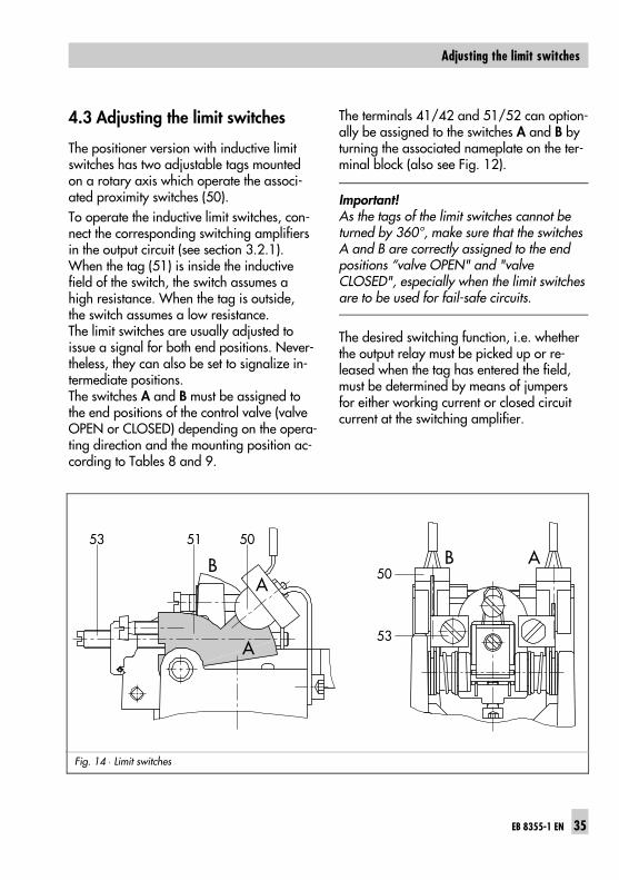
4.3 Adjusting the limit switches
The positioner version with inductive limitswitches has two adjustable tags mountedon a rotary axis which operate the associ-ated proximity switches (50).To operate the inductive limit switches, con-nect the corresponding switching amplifiersin the output circuit (see section 3.2.1).When the tag (51) is inside the inductivefield of the switch, the switch assumes ahigh resistance. When the tag is outside,the switch assumes a low resistance.The limit switches are usually adjusted toissue a signal for both end positions. Never-theless, they can also be set to signalize in-termediate positions.The switches A and B must be assigned tothe end positions of the control valve (valveOPEN or CLOSED) depending on the opera-ting direction and the mounting position ac-cording to Tables 8 and 9.
The terminals 41/42 and 51/52 can option-ally be assigned to the switches A and B byturning the associated nameplate on the ter-minal block (also see Fig. 12).
Important!As the tags of the limit switches cannot beturned by 360°, make sure that the switchesA and B are correctly assigned to the endpositions “valve OPEN" and "valveCLOSED", especially when the limit switchesare to be used for fail-safe circuits.
The desired switching function, i.e. whetherthe output relay must be picked up or re-leased when the tag has entered the field,must be determined by means of jumpersfor either working current or closed circuitcurrent at the switching amplifier.
Fig. 14 ⋅ Limit switches
EB 8355-1 EN 35
Adjusting the limit switches
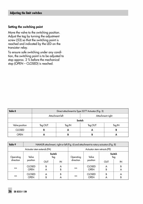
Setting the switching point
Move the valve to the switching position.Adjust the tag by turning the adjustmentscrew (53) so that the switching point isreached and indicated by the LED on thetransistor relay.To ensure safe switching under any condi-tion, the switching point is to be adjusted tostop approx. 2 % before the mechanicalstop (OPEN – CLOSED) is reached.
Table 8 Direct attachment to Type 3277 Actuator (Fig. 3)
Attachment left Attachment right
Switch
Valve position Tag OUT Tag IN Tag OUT Tag IN
CLOSED B A A B
OPEN A B B A
Table 9 NAMUR attachment, right or left (Fig. 6) and attachment to rotary actuators (Fig. 8)
Actuator stem extends (FA) Actuator stem retracts (FE)
Operatingdirection
Valveposition
SwitchTag Operating
directionValve
position
SwitchTag
OUT IN OUT IN
>>CLOSEDOPEN
BA
AB
>>CLOSEDOPEN
AB
BA
<>CLOSEDOPEN
AB
BA
<>CLOSEDOPEN
BA
AB
36 EB 8355-1 EN
Adjusting the limit switches
4.4 Adjusting the position transmit-ter
Important!The starting point (zero) and upper rangevalue (span) must be set before calibratingthe position transmitter.
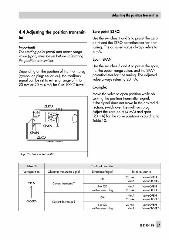
Depending on the position of the 4-pin plug(symbol on plug: >> or <>), the feedbacksignal can be set to either a range of 4 to20 mA or 20 to 4 mA for 0 to 100 % travel.
Zero point (ZERO)
Use the switches 1 and 2 to preset the zeropoint and the ZERO potentiometer for fine-tuning. The adjusted value always refers to4 mA.
Span (SPAN)
Use the switches 3 and 4 to preset the span,i.e. the upper range value, and the SPANpotentiometer for fine-tuning. The adjustedvalue always refers to 20 mA.
Example:
Move the valve to open position while ob-serving the position transmitter signal.If the signal does not move in the desired di-rection, switch over the multi-pin plug.Adjust the zero point (4 mA) and span(20 mA) for the valve positions according toTable 10.
Fig. 15 ⋅ Position transmitter
Table 10 Position transmitter
Valve position Observed transmitter signal Direction of signal Set zero/span to
OPEN
CLOSED
Current increases ↑OK
20 mA 4 mA
Valve OPENValve CLOSED
Not OK→ Reconnect plug
4 mA 20 mA
Valve OPENValve CLOSED
Current decreases ↓OK
4 mA 20 mA
Valve OPENValve CLOSED
Not OK→ Reconnect plug
20 mA 4 mA
Valve OPENValve CLOSED
ZEROSPAN
12
34
SPAN
ZERO
EB 8355-1 EN 37
Adjusting the position transmitter
Adjusting the zero point
1. Use the input signal of the positioner tomove the valve to closed position (valveCLOSED — travel 0 %).
2. The ammeter must now indicate ap-prox. 4 mA.
3. Correct smaller deviations on the ZEROpotentiometer until the meter showsexactly 4 mA.If deviations are too high and cannotbe corrected using the potentiometer(adjustment range of approx. 20 turns),set the switches 1 and 2 to indicate anmA value which is within the adjustmentrange of the ZERO potentiometer.
4. Set the zero point to exactly 4 mA usingthe ZERO potentiometer.
Adjusting the span
1. Use the input signal of the positioner tomove the valve to open position (valveOPEN — travel 100 %).
2. The ammeter must now indicate ap-prox. 20 mA.
3. Correct smaller deviations on the SPANpotentiometer until the meter showsexactly 20 mA.If deviations are too high, set the swit-ches 3 and 4 to indicate an mA valuewhich is within the adjustment range ofthe SPAN potentiometer.
4. Turn the SPAN potentiometer until themeter shows exactly 20 mA.Since zero and span have a mutual in-fluence on each other, repeat the correc-tion procedure at both potentiometersuntil both values are correct.
Note on adjusting the position transmitterfor positioners with NAMUR adapter hous-ingWhen the positioner and the position trans-mitter signal have different operating direc-tions (<< and <>), the zero point of thetransmitter signal could be unadjustabledue to the additional deflection caused bythe angle bracket (28, Fig. 7) of the adapterhousing.If so, readjust the black pointer (sec-tion 2.2.2) so that the sensor of the positiontransmitter reaches the control range.Unscrew the clamp. For “Actuator stem extends” (FA), shift thepointer upward towards the actuator; for"Actuator stem retracts" (FE), shift thepointer downward towards the valve.For valves with rod-type yoke, slightly shiftthe positioner on the rod in downward (FE)or upward (FA) direction.
Important!Every time you have made a change as de-scribed above, the zero point and span ofthe positioner must be readjusted beforecalibrating the position transmitter.
38 EB 8355-1 EN
Adjusting the position transmitter
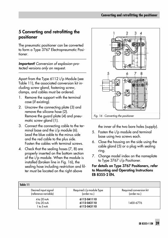
5 Converting and retrofitting thepositioner
The pneumatic positioner can be convertedto form a Type 3767 Electropneumatic Posi-tioner.
Important! Conversion of explosion-pro-tected versions only on request.
Apart from the Type 6112 i/p Module (seeTable 11), the associated conversion kit in-cluding screw gland, fastening screw,clamps, and cables must be ordered.1. Remove the support with the terminal
case (if existing).2. Unscrew the connecting plate (3) and
remove the silicone hose (2). Remove the guard plate (4) and pneu-matic screw gland (1).
3. Connect the connecting cable to the ter-minal base and the i/p module (6).Lead the blue cable to the minus sideand the red cable to the plus side.Fasten the cables with terminal screws.
4. Check that the sealing hoses (7, 8) areproperly inserted on the bottom sectionof the i/p module. When the module isinstalled (broken line in Fig. 16), thesealing hose including restriction and fil-ter must be located on the right above
the inner of the two bore holes (supply).5. Fasten the i/p module and terminal
base using two screws each.6. Close the housing on the side using the
cable gland (5) or a plug with sealingring.
7. Change model index on the nameplateto Type 3767 i/p Positioner.
For details on Type 3767 Positioners, referto Mounting and Operating InstructionsEB 8355-2 EN.
Fig. 16 ⋅ Converting the positioner
1 2 3 4
5 6 7 8
Table 11
Desired input signal(reference variable)
Required i/p module Type(order no.)
Required conversion kit(order no.)
4 to 20 mA0 to 20 mA1 to 5 mA
6112-0411106112-0421106112-043110
1400-6776
EB 8355-1 EN 39
Converting and retrofitting the positioner
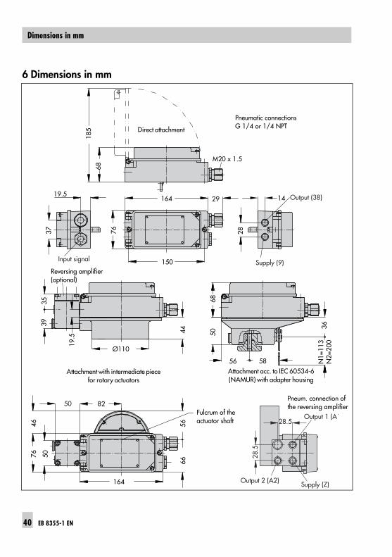
6 Dimensions in mm
44
19.5
3539
164
4676 50
36N
1=11
3 N
2=20
0
5856
68
28
1429
150
16419.5
37
6818
5
76
Ø110
82
5666
50
M20 x 1.5
28.5
28.5
Output 1 (A1
Output 2 (A2) Supply (Z)
50
Output (38)
Supply (9)Input signal
Reversing amplifier(optional)
Fulcrum of theactuator shaft
Direct attachment
Pneum. connection ofthe reversing amplifier
Pneumatic connectionsG 1/4 or 1/4 NPT
Attachment with intermediate piecefor rotary actuators
Attachment acc. to IEC 60534-6(NAMUR) with adapter housing
40 EB 8355-1 EN
Dimensions in mm
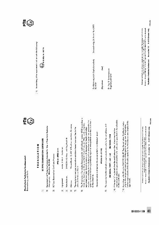
EB 8355-1 EN 41
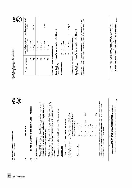
42 EB 8355-1 EN
EB 8355-1 EN 43
44 EB 8355-1 EN
EB 8355-1 EN 45
46 EB 8355-1 EN
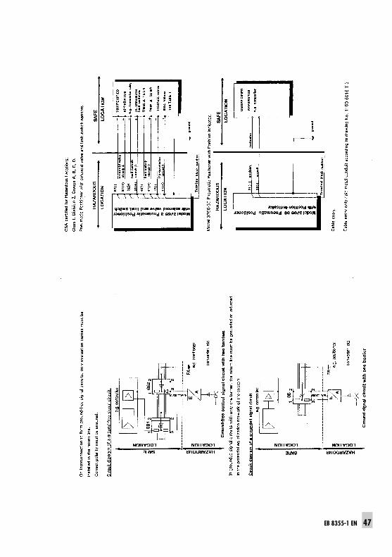
EB 8355-1 EN 47
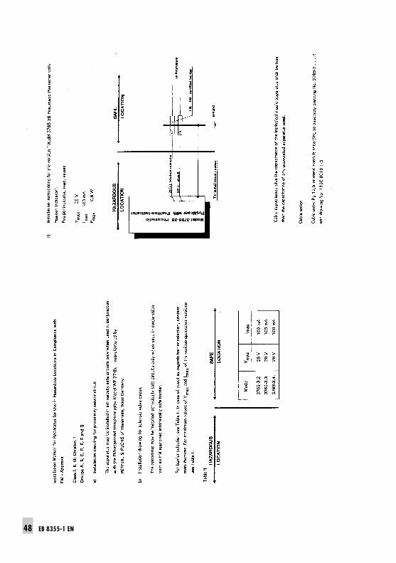
48 EB 8355-1 EN
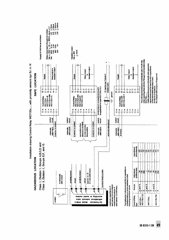
EB 8355-1 EN 49
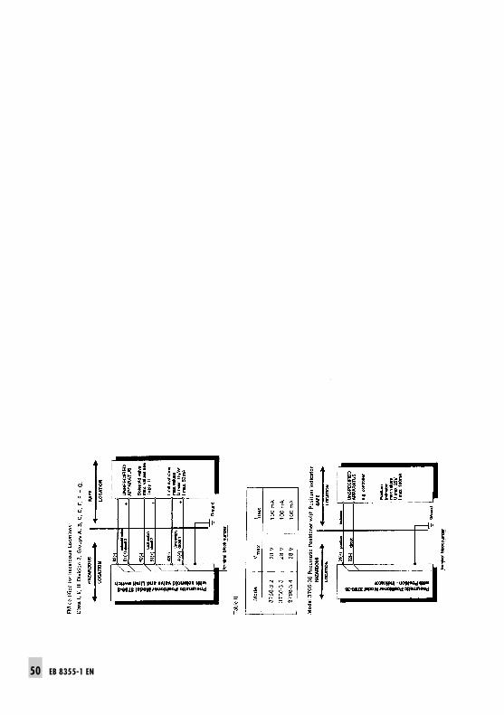
50 EB 8355-1 EN

EB 8355-1 EN 51

SAMSON AG ⋅ MESS- UND REGELTECHNIKWeismüllerstraße 3 ⋅ 60314 Frankfurt am Main ⋅ GermanyPhone: +49 69 4009-0 ⋅ Fax: +49 69 4009-1507Internet: http://www.samson.de EB 8355-1 EN S/
Z 20
04-0
3