Embed Size (px)
Citation preview
MOTOX Geared MotorsCatalog D 87.1 · 2011
MOTOX
Answers for industry.
© Siemens AG 2011
Low-Voltage Motors D 81.1IEC Squirrel-Cage Motors
E86060-K5581-A111-A3-7600
FLENDER MD 10.1Standard Couplings
E86060-K5710-A111-A3-7600
SINAMICS G110, SINAMICS G120 D 11.1Standard InvertersSINAMICS G110D, SINAMICS G120DDistributed Inverters
E86060-K5511-A111-A6-7600
SINAMICS G130 D 11Drive Converter Chassis Units SINAMICS G150Drive Converter Cabinet Units
E86060-K5511-A101-A4-7600
MICROMASTER DA 51.2MICROMASTER 420/430/440Inverters0.12 kW to 250 kW
E86060-K5151-A121-A6-7600
MICROMASTER/COMBIMASTER DA 51.3MICROMASTER 411 InverterCOMBIMASTER 411Distributed Drive Solutions
E86060-K5251-A131-A2-7600
Industrial Communication IK PIPart 5: SIMATIC ET 200 Distributed I/OET 200S FC Frequency converter
E86060-K6710-A101-B6-7600
AC NEMA & IEC Motors D 81.2 Further details available on the U.S./Internet at: Canada
Only PDFhttp://www.sea.siemens.com/motors
MOTOX Konfigurator MOTOXMOTOX ConfiguratorInformation / Configuration(CD)
E86060-D5203-A100-A5-X100
Additional documentation
You will find all information material, such as brochures, catalogs, manuals and operating instructions for standard drive systems up-to-date on the Internet at the address:
http://www.siemens.com/gearedmotors
You can order the listed documentation or download it in common file formats (PDF, ZIP).
Related catalogs
© Siemens AG 2011
MOTOXGeared Motors
Catalog D 87.1 · 2011
Supersedes:Catalogs D 87.1 · 2008 and 2010
The products contained in this catalog can also be found in the electronic catalog MOTOX Configurator 7.4.Order No.: E86060-D5203-A100-A5-X100 (CD-ROM)
Please contact your local Siemens branch
© Siemens AG 2011
The products and sys-tems described in this catalog are manufac-tured/distributed under application of a certified quality management system in accordance with DIN EN ISO 9001 (Certified Registration No. DE-409908 QM08). The certificate is recognized by all IQNet countries.
Introduction 1
Helical geared motors 2
Parallel shaft geared motors 3
Bevel helical geared motors 4
Helical worm geared motors 5
Worm geared motors 6
Input units 7
Motors 8
Appendix 9
© Siemens AG 2011
2 Siemens D 87.1 · 2011
© Siemens AG 2011
3Siemens D 87.1 · 2011
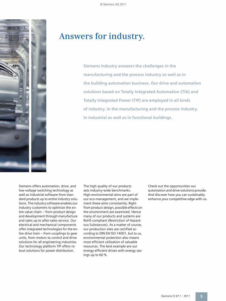
Answers for industry.
Siemens Industry answers the challenges in the
manufacturing and the process industry as well as in
the building automation business. Our drive and automation
solutions based on Totally Integrated Automation (TIA) and
Totally Integrated Power (TIP) are employed in all kinds
of industry. In the manufacturing and the process industry.
In industrial as well as in functional buildings.
Siemens offers automation, drive, and low-voltage switching technology as well as industrial software from stan-dard products up to entire industry solu-tions. The industry software enables our industry customers to optimize the en-tire value chain – from product design and development through manufacture and sales up to after-sales service. Our electrical and mechanical components offer integrated technologies for the en-tire drive train – from couplings to gear units, from motors to control and drive solutions for all engineering industries. Our technology platform TIP offers ro-bust solutions for power distribution.
The high quality of our products sets industry-wide benchmarks. High environmental aims are part of our eco-management, and we imple-ment these aims consistently. Right from product design, possible effects on the environment are examined. Hence many of our products and systems are RoHS compliant (Restriction of Hazard-ous Substances). As a matter of course, our production sites are certified ac-cording to DIN EN ISO 14001, but to us, environmental protection also means most efficient utilization of valuable resources. The best example are our energy-efficient drives with energy sav-ings up to 60 %.
Check out the opportunities our automation and drive solutions provide. And discover how you can sustainably enhance your competitive edge with us.
© Siemens AG 2011
4 Siemens D 87.1 · 2011
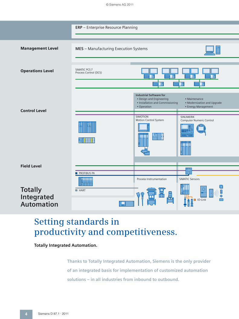
Field Level
Control Level
Operations Level
Management Level
ERP – Enterprise Resource Planning
MES – Manufacturing Execution Systems
SIMATIC PCS 7Process Control (DCS)
• Maintenance• Modernization and Upgrade• Energy Management
Industrial Software for• Design and Engineering• Installation and Commissioning• Operation
Process Instrumentation SIMATIC Sensors
SINUMERIK Computer Numeric Control
SIMOTIONMotion Control System
IO-Link
HART
PROFIBUS PA
Totally IntegratedAutomation
Setting standards in productivity and competitiveness.Totally Integrated Automation.
Thanks to Totally Integrated Automation, Siemens is the only provider
of an integrated basis for implementation of customized automation
solutions – in all industries from inbound to outbound.
© Siemens AG 2011
5Siemens D 87.1 · 2011
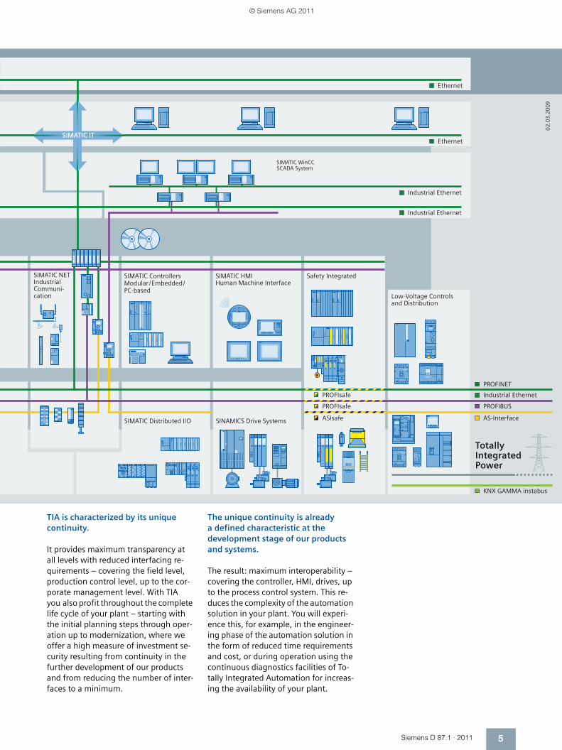
SIMATIC WinCC SCADA System
SIMATIC NETIndustrial Communi-cation
SIMATIC ControllersModular/Embedded/PC-based
SIMATIC HMIHuman Machine Interface
Safety Integrated
Low-Voltage Controlsand Distribution
SIMATIC Distributed I/O SINAMICS Drive Systems
KNX GAMMA instabus
PROFIBUSPROFIsafe
PROFIsafe Industrial Ethernet
PROFINET
AS-Interface
Industrial Ethernet
Ethernet
Industrial Ethernet
Ethernet
Totally Integrated Power
ASIsafe
SIMATIC IT
02
.03
.20
09
TIA is characterized by its unique continuity.
It provides maximum transparency at all levels with reduced interfacing re-quirements – covering the field level, production control level, up to the cor-porate management level. With TIA you also profit throughout the complete life cycle of your plant – starting with the initial planning steps through oper-ation up to modernization, where we offer a high measure of investment se-curity resulting from continuity in the further development of our products and from reducing the number of inter-faces to a minimum.
The unique continuity is already a defined characteristic at the development stage of our products and systems.
The result: maximum interoperability – covering the controller, HMI, drives, up to the process control system. This re-duces the complexity of the automation solution in your plant. You will experi-ence this, for example, in the engineer-ing phase of the automation solution in the form of reduced time requirements and cost, or during operation using the continuous diagnostics facilities of To-tally Integrated Automation for increas-ing the availability of your plant.
© Siemens AG 2011
6 Siemens D 87.1 · 2011
Integrated power distribution from one source.Totally Integrated Power.
© Siemens AG 2011
7Siemens D 87.1 · 2011
Products and systemsMedium voltage Transformers Low voltage Installation
technologyBuildingautomation
Communication
Processes /industrial automation
Industrial Ethernet
Planning and system configuration
≤ 110 kV
IEC 61850
PROFIBUS
PROFINET
KNX EIB
BACnet
03.0
4.20
08
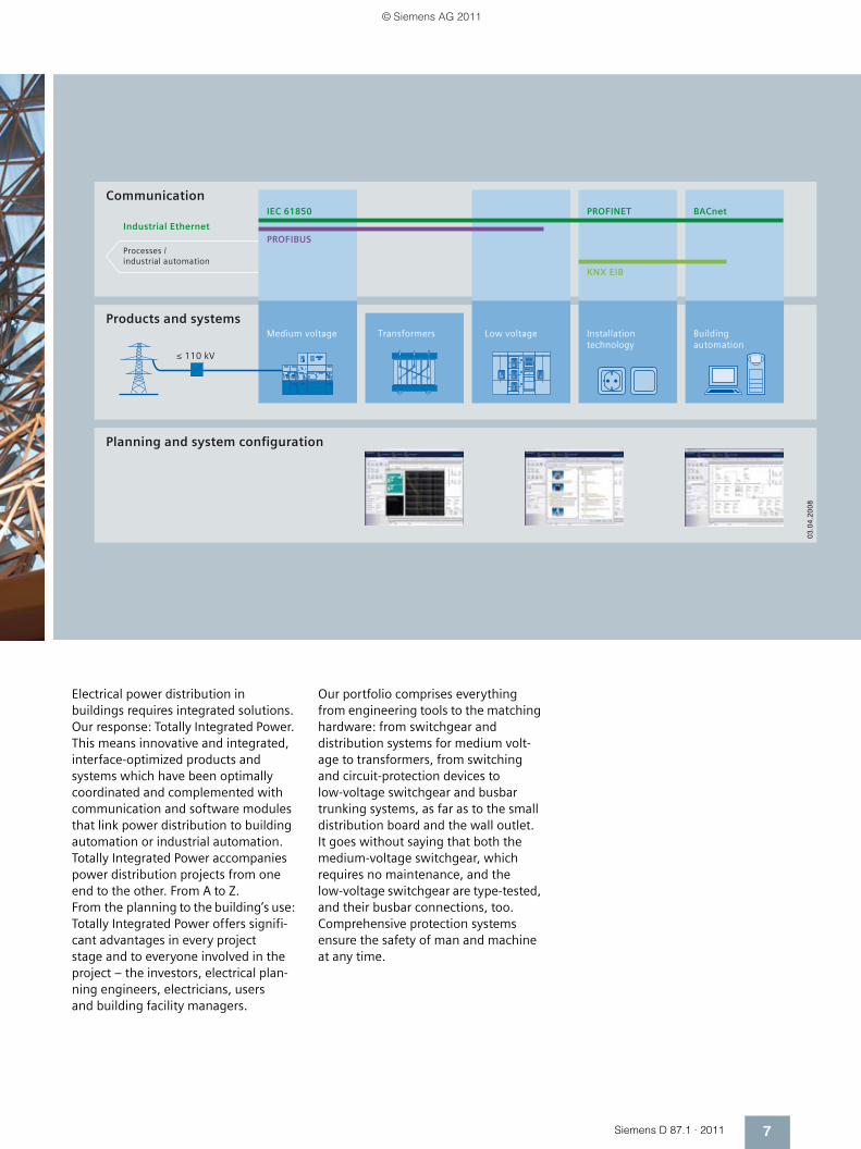
Electrical power distribution in buildings requires integrated solutions. Our response: Totally Integrated Power. This means innovative and integrated, interface-optimized products and systems which have been optimally coordinated and complemented with communication and software modules that link power distribution to building automation or industrial automation. Totally Integrated Power accompanies power distribution projects from one end to the other. From A to Z. From the planning to the building’s use: Totally Integrated Power offers signifi-cant advantages in every project stage and to everyone involved in the project – the investors, electrical plan-ning engineers, electricians, users and building facility managers.
Our portfolio comprises everything from engineering tools to the matching hardware: from switchgear and distribution systems for medium volt-age to transformers, from switching and circuit-protection devices to low-voltage switchgear and busbar trunking systems, as far as to the small distribution board and the wall outlet. It goes without saying that both the medium-voltage switchgear, which requires no maintenance, and the low-voltage switchgear are type-tested, and their busbar connections, too. Comprehensive protection systems ensure the safety of man and machine at any time.
© Siemens AG 2011

SelectingFind your products in the structure tree, in the new "Bread-crumb" navigation or with the integral search machine with expert functions. Electronic configurators are also integrated into the Mall. Enter the various characteristic values and the appropriate product will be dis-played with the relevant order numbers. You can save configurations, load them and reset them to their initial status.
OrderingYou can load the products that you have selected in this way into the shopping basket at a click of the mouse. You can create your own tem-plates and you will be informed about the availability of the products in your shopping cart. You can load the completed parts lists directly into Excel or Word.
Delivery statusWhen you have sent the order, you will receive a short e-mail confir-mation which you can print out or save. With a click on "Carrier", you will be directly connected to the website of the carrier where you can easily track the delivery status.
Added value due to additional informationSo you have found your product and want more information about it? In just a few clicks of the mouse, you will arrive at the image data base, manuals and operating instructions. Create your own user documen-tation with My Documentation Manager.Also available are FAQs, software downloads, certificates and techni-cal data sheets as well as our training programs. In the image database you will find, depending on the product, 2D/3Dgraphics, dimension drawings and exploded drawings, characteristic curves or circuit diagrams which you can download.
Convinced? We look forward to your visit!
Much more than a catalog.The Industry Mall.
You have a catalog in your hands that will serve you well for selecting and ordering your products. But have you heard of the electronic online cata-log (the Industry Mall) and all its benefits? Take a look around it sometime:
www.siemens.com/industrymall
© Siemens AG 2011
Siemens D 87.1 · 2011
1General technical data
1/33 Overview of drive sizing data1/34 Important drive technology variables1/36 Overview1/36 Designs in accordance with standards
and specifications1/41 Explosion protection as per ATEX1/42 Standards1/42 Fits1/43 Degrees of protection1/43 Direction of rotation of geared motors1/44 Power ratings and torques1/44 Speeds1/44 Noise1/44 Weight of geared motors1/44 Three-phase AC motors1/44 Brakes1/45 Lubricants1/46 Long-term preservation1/47 Surface treatment1/48 Increased protection against humidity
and tropical climate1/48 Increased protection against acid and
alkali1/49 Rating plate1/49 Documentation
Introduction
Guide to selecting and ordering geared motors
1/2 Description of the range of geared motors
1/4 Guide to drive selection1/5 Order number code1/7 Determining the gearbox type
in accordance with the power rating and output speed
1/10 Determining the gearbox type in accordance with the max. torque, transmission ratio and size
1/13 Overview of "special versions"
Configuring guide1/18 Determining the drive data1/19 Efficiency of the geared motor1/20 Determining the required service factor1/21 Required service factor 1/22 Maximum motor speed1/22 Ambient temperature 1/22 Required output torque 1/22 Selection of the gearbox 1/23 Reduced-backlash gearbox version1/23 Permissible radial force1/25 Determining the operating mode1/28 Coolant temperature and site altitude1/28 Selecting the brake1/29 Selecting the braking torque
Special versions1/30 Motors for inverter-fed operation1/31 Determining the permissible number of
startings 1/32 Checking the input torque for mounted
units
© Siemens AG 2011
MOTOX Geared MotorsIntroduction
Guide to selecting and ordering geared motors
1/2 Siemens D 87.1 · 2011
1 ■ Description of the range of geared motors
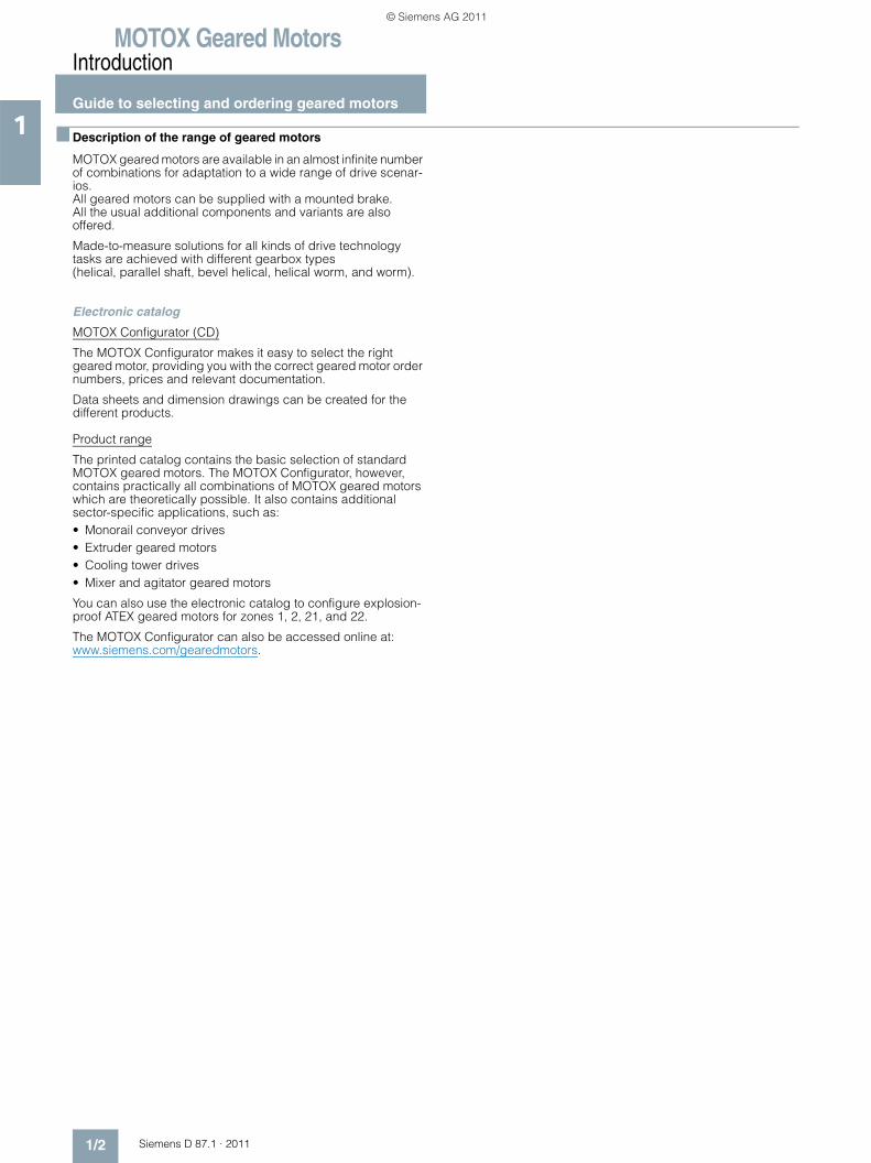
MOTOX geared motors are available in an almost infinite number of combinations for adaptation to a wide range of drive scenar-ios. All geared motors can be supplied with a mounted brake. All the usual additional components and variants are also offered.
Made-to-measure solutions for all kinds of drive technology tasks are achieved with different gearbox types (helical, parallel shaft, bevel helical, helical worm, and worm).
Electronic catalog
MOTOX Configurator (CD)
The MOTOX Configurator makes it easy to select the right geared motor, providing you with the correct geared motor order numbers, prices and relevant documentation.
Data sheets and dimension drawings can be created for the different products.
Product range
The printed catalog contains the basic selection of standard MOTOX geared motors. The MOTOX Configurator, however, contains practically all combinations of MOTOX geared motors which are theoretically possible. It also contains additional sector-specific applications, such as:• Monorail conveyor drives• Extruder geared motors• Cooling tower drives• Mixer and agitator geared motors
You can also use the electronic catalog to configure explosion-proof ATEX geared motors for zones 1, 2, 21, and 22.
The MOTOX Configurator can also be accessed online at: www.siemens.com/gearedmotors.
© Siemens AG 2011
MOTOX Geared MotorsIntroduction
Guide to selecting and ordering geared motors
1/3Siemens D 87.1 · 2011
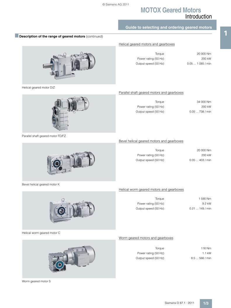
1■ Description of the range of geared motors (continued)
Helical geared motor D/Z
Helical geared motors and gearboxes
Torque 20 000 Nm
Power rating (50 Hz) 200 kW
Output speed (50 Hz) 0.05 ... 1 085 / min
Parallel shaft geared motor FD/FZ
Parallel shaft geared motors and gearboxes
Torque 34 000 Nm
Power rating (50 Hz) 200 kW
Output speed (50 Hz) 0.05 ... 738 / min
Bevel helical geared motor K
Bevel helical geared motors and gearboxes
Torque 20 000 Nm
Power rating (50 Hz) 200 kW
Output speed (50 Hz) 0.05 ... 403 / min
Helical worm geared motor C
Helical worm geared motors and gearboxes
Torque 1 590 Nm
Power rating (50 Hz) 9.2 kW
Output speed (50 Hz) 0.21 ... 149 / min
Worm geared motor S
Worm geared motors and gearboxes
Torque 116 Nm
Power rating (50 Hz) 1.1 kW
Output speed (50 Hz) 8.5 ... 566 / min
© Siemens AG 2011
MOTOX Geared MotorsIntroduction
Guide to selecting and ordering geared motors
1/4 Siemens D 87.1 · 2011
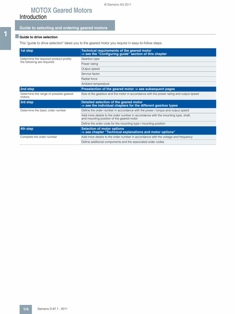
1 ■ Guide to drive selection
This "guide to drive selection" takes you to the geared motor you require in easy-to-follow steps.
1st step Technical requirements of the geared motor -> see the "Configuring guide" section of this chapter
Determine the required product profile, the following are required:
Gearbox type
Power rating
Output speed
Service factor
Radial force
Ambient temperature
2nd step Preselection of the geared motor -> see subsequent pagesDetermine the range of possible geared motors
Size of the gearbox and the motor in accordance with the power rating and output speed
3rd step Detailed selection of the geared motor -> see the individual chapters for the different gearbox types
Determine the basic order number Define the order number in accordance with the power / torque and output speed
Add more details to the order number in accordance with the mounting type, shaft, and mounting position of the geared motor
Define the order code for the mounting type / mounting position
4th step Selection of motor options -> see chapter "Technical explanations and motor options"
Complete the order number Add more details to the order number in accordance with the voltage and frequency
Define additional components and the associated order codes
© Siemens AG 2011
MOTOX Geared MotorsIntroduction
Guide to selecting and ordering geared motors
1/5Siemens D 87.1 · 2011
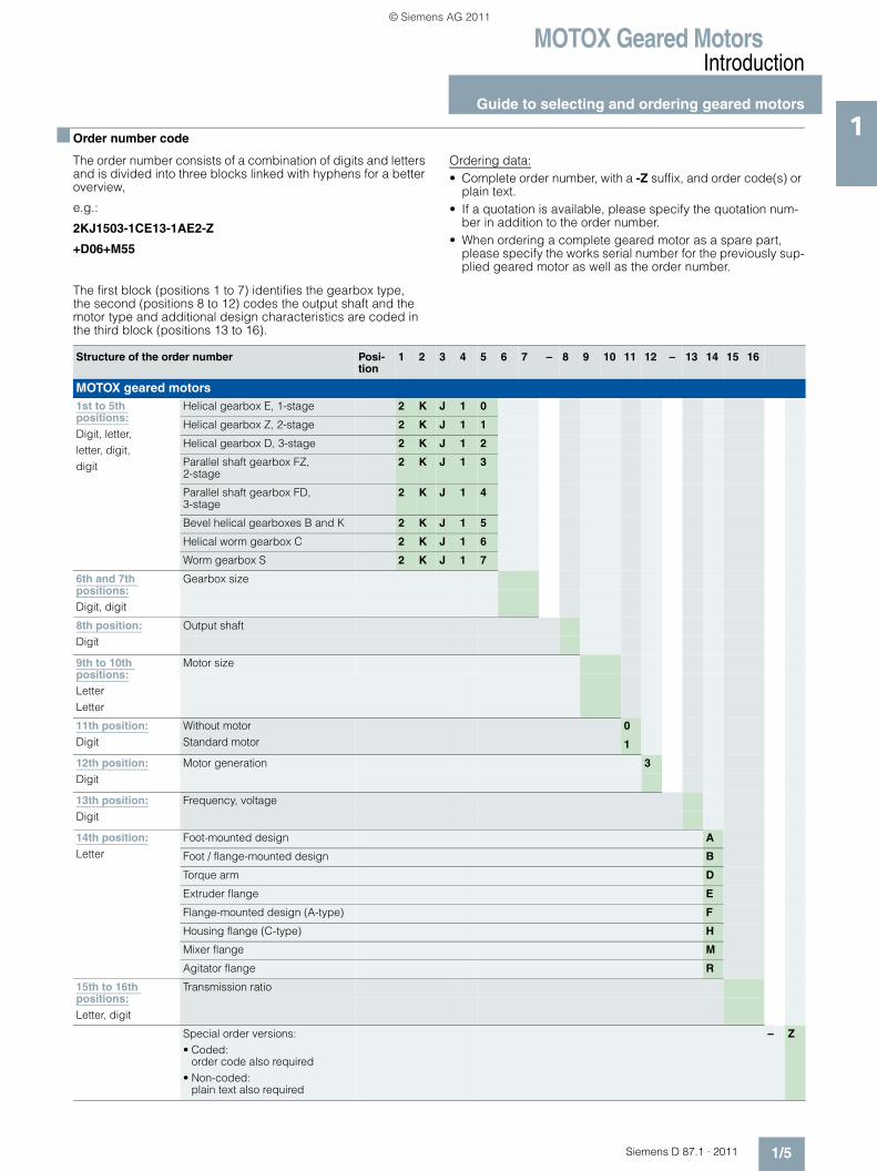
1■ Order number code
The order number consists of a combination of digits and letters and is divided into three blocks linked with hyphens for a better overview,
e.g.:
2KJ1503-1CE13-1AE2-Z
+D06+M55
The first block (positions 1 to 7) identifies the gearbox type, the second (positions 8 to 12) codes the output shaft and the motor type and additional design characteristics are coded in the third block (positions 13 to 16).
Ordering data:• Complete order number, with a -Z suffix, and order code(s) or
plain text.• If a quotation is available, please specify the quotation num-
ber in addition to the order number.• When ordering a complete geared motor as a spare part,
please specify the works serial number for the previously sup-plied geared motor as well as the order number.
Structure of the order number Posi-tion
1 2 3 4 5 6 7 – 8 9 10 11 12 – 13 14 15 16
MOTOX geared motors1st to 5th positions:Digit, letter, letter, digit,digit
Helical gearbox E, 1-stage 2 K J 1 0
Helical gearbox Z, 2-stage 2 K J 1 1
Helical gearbox D, 3-stage 2 K J 1 2
Parallel shaft gearbox FZ, 2-stage
2 K J 1 3
Parallel shaft gearbox FD, 3-stage
2 K J 1 4
Bevel helical gearboxes B and K 2 K J 1 5
Helical worm gearbox C 2 K J 1 6
Worm gearbox S 2 K J 1 7
6th and 7th positions:Digit, digit
Gearbox size
8th position:Digit
Output shaft
9th to 10th positions:LetterLetter
Motor size
11th position:Digit
Without motorStandard motor
0
1
12th position:Digit
Motor generation 3
13th position:Digit
Frequency, voltage
14th position:Letter
Foot-mounted design A
Foot / flange-mounted design B
Torque arm D
Extruder flange E
Flange-mounted design (A-type) F
Housing flange (C-type) H
Mixer flange M
Agitator flange R
15th to 16th positions:Letter, digit
Transmission ratio
Special order versions:• Coded:
order code also required• Non-coded:
plain text also required
– Z
© Siemens AG 2011
MOTOX Geared MotorsIntroduction
Guide to selecting and ordering geared motors
1/6 Siemens D 87.1 · 2011
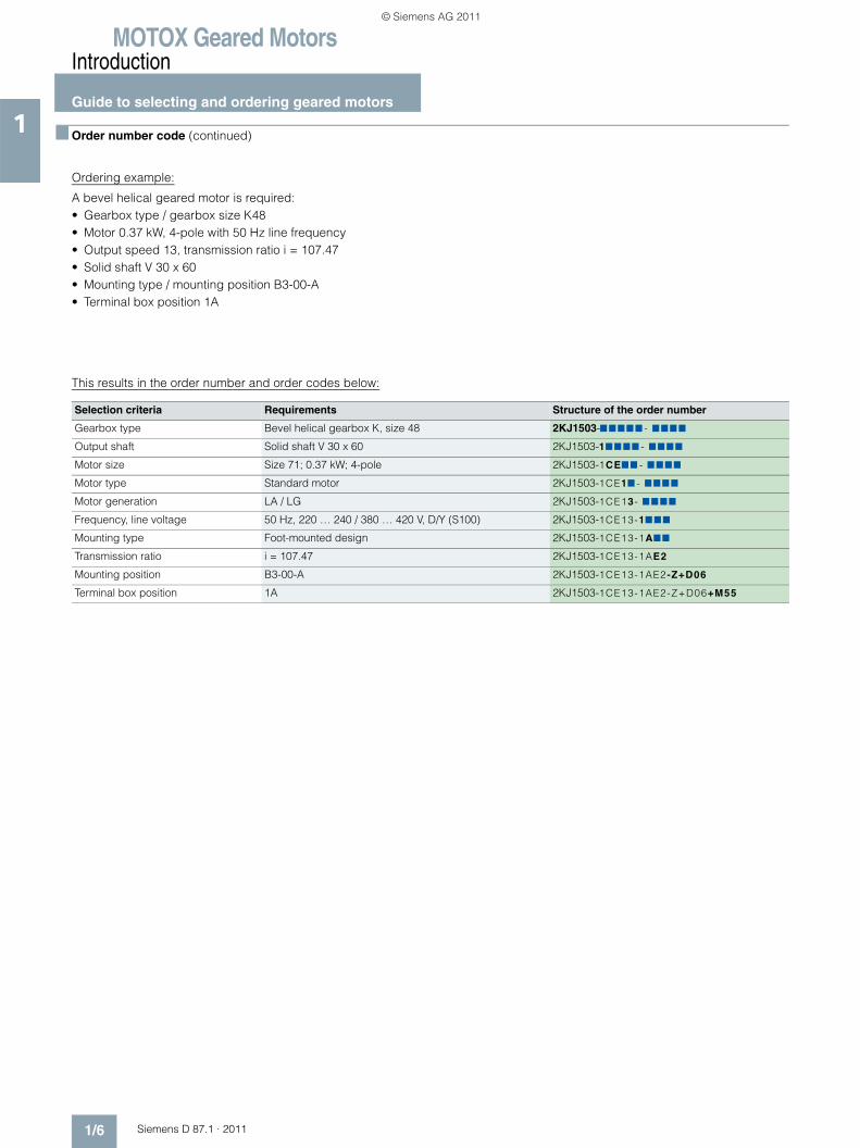
1 ■ Order number code (continued)
Ordering example:
A bevel helical geared motor is required:• Gearbox type / gearbox size K48• Motor 0.37 kW, 4-pole with 50 Hz line frequency• Output speed 13, transmission ratio i = 107.47• Solid shaft V 30 x 60• Mounting type / mounting position B3-00-A• Terminal box position 1A
This results in the order number and order codes below:
Selection criteria Requirements Structure of the order number
Gearbox type Bevel helical gearbox K, size 48 2KJ1503-7 777 7 - 777 7
Output shaft Solid shaft V 30 x 60 2KJ1503-177 77 - 77 77
Motor size Size 71; 0.37 kW; 4-pole 2KJ1503-1CE77 - 7 777
Motor type Standard motor 2KJ1503-1CE17 - 777 7
Motor generation LA / LG 2KJ1503-1CE13- 77 77
Frequency, line voltage 50 Hz, 220 … 240 / 380 … 420 V, D/Y (S100) 2KJ1503-1CE13-17 77
Mounting type Foot-mounted design 2KJ1503-1CE13-1A77
Transmission ratio i = 107.47 2KJ1503-1CE13-1AE2
Mounting position B3-00-A 2KJ1503-1CE13-1AE2 -Z+D06
Terminal box position 1A 2KJ1503-1CE13-1AE2-Z+D06+M55
© Siemens AG 2011
MOTOX Geared MotorsIntroduction
Guide to selecting and ordering geared motors
1/7Siemens D 87.1 · 2011
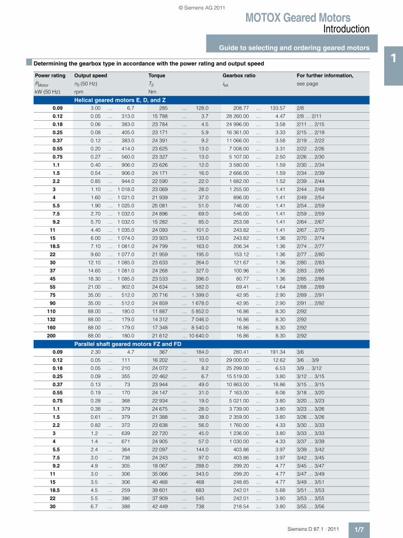
1■ Determining the gearbox type in accordance with the power rating and output speed
Power rating Output speed Torque Gearbox ratio For further information,
PMotor n2 (50 Hz) T2 itot see page
kW (50 Hz) rpm Nm
Helical geared motors E, D, and Z0.09 3.00 … 6.7 285 … 128.0 208.77 … 133.57 2/8
0.12 0.05 … 313.0 15 788 … 3.7 28 260.00 … 4.47 2/8 … 2/11
0.18 0.06 … 383.0 23 784 … 4.5 24 996.00 … 3.58 2/11 … 2/15
0.25 0.08 … 405.0 23 171 … 5.9 16 361.00 … 3.33 2/15 … 2/19
0.37 0.12 … 383.0 24 391 … 9.2 11 066.00 … 3.58 2/19 … 2/22
0.55 0.20 … 414.0 23 625 … 13.0 7 008.00 … 3.31 2/22 … 2/26
0.75 0.27 … 560.0 23 327 … 13.0 5 107.00 … 2.50 2/26 … 2/30
1.1 0.40 … 906.0 23 626 … 12.0 3 580.00 … 1.59 2/30 … 2/34
1.5 0.54 … 906.0 24 171 … 16.0 2 666.00 … 1.59 2/34 … 2/39
2.2 0.85 … 944.0 22 590 … 22.0 1 682.00 … 1.52 2/39 … 2/44
3 1.10 … 1 018.0 23 069 … 28.0 1 255.00 … 1.41 2/44 … 2/49
4 1.60 … 1 021.0 21 939 … 37.0 896.00 … 1.41 2/49 … 2/54
5.5 1.90 … 1 025.0 25 081 … 51.0 746.00 … 1.41 2/54 … 2/59
7.5 2.70 … 1 032.0 24 896 … 69.0 546.00 … 1.41 2/59 … 2/59
9.2 5.70 … 1 032.0 15 282 … 85.0 253.08 … 1.41 2/64 … 2/67
11 4.40 … 1 035.0 24 093 … 101.0 243.82 … 1.41 2/67 … 2/70
15 6.00 … 1 074.0 23 923 … 133.0 243.82 … 1.36 2/70 … 2/74
18.5 7.10 … 1 081.0 24 799 … 163.0 206.34 … 1.36 2/74 … 2/77
22 9.60 … 1 077.0 21 959 … 195.0 153.12 … 1.36 2/77 … 2/80
30 12.10 … 1 085.0 23 633 … 264.0 121.67 … 1.36 2/80 … 2/83
37 14.60 … 1 081.0 24 268 … 327.0 100.96 … 1.36 2/83 … 2/85
45 18.30 … 1 085.0 23 533 … 396.0 80.77 … 1.36 2/85 … 2/88
55 21.00 … 902.0 24 634 … 582.0 69.41 … 1.64 2/88 … 2/89
75 35.00 … 512.0 20 716 … 1 399.0 42.95 … 2.90 2/89 … 2/91
90 35.00 … 512.0 24 859 … 1 678.0 42.95 … 2.90 2/91 … 2/92
110 88.00 … 180.0 11 887 … 5 852.0 16.86 … 8.30 2/92
132 88.00 … 179.0 14 312 … 7 046.0 16.86 … 8.30 2/92
160 88.00 … 179.0 17 348 … 8 540.0 16.86 … 8.30 2/92
200 88.00 … 180.0 21 612 … 10 640.0 16.86 … 8.30 2/92
Parallel shaft geared motors FZ and FD0.09 2.30 … 4.7 367 … 184.0 280.41 … 191.34 3/6
0.12 0.05 … 111 16 202 … 10.0 29 000.00 … 12.62 3/6 … 3/9
0.18 0.05 … 210 24 072 … 8.2 25 299.00 … 6.53 3/9 … 3/12
0.25 0.09 … 355 22 462 … 6.7 15 519.00 … 3.80 3/12 … 3/15
0.37 0.13 … 73 23 944 … 49.0 10 863.00 … 18.86 3/15 … 3/15
0.55 0.19 … 170 24 147 … 31.0 7 163.00 … 8.06 3/18 … 3/20
0.75 0.28 … 368 22 934 … 19.0 5 021.00 … 3.80 3/20 … 3/23
1.1 0.38 … 379 24 675 … 28.0 3 739.00 … 3.80 3/23 … 3/26
1.5 0.61 … 379 21 388 … 38.0 2 359.00 … 3.80 3/26 … 3/26
2.2 0.82 … 372 23 638 … 56.0 1 760.00 … 4.33 3/30 … 3/33
3 1.2 … 639 22 720 … 45.0 1 236.00 … 3.80 3/33 … 3/33
4 1.4 … 671 24 905 … 57.0 1 030.00 … 4.33 3/37 … 3/39
5.5 2.4 … 364 22 097 … 144.0 403.86 … 3.97 3/39 … 3/42
7.5 3.0 … 738 24 243 … 97.0 403.86 … 3.97 3/42 … 3/45
9.2 4.9 … 305 18 067 … 288.0 299.20 … 4.77 3/45 … 3/47
11 3.0 … 306 35 066 … 343.0 299.20 … 4.77 3/47 … 3/49
15 3.5 … 306 40 468 … 468 248.85 … 4.77 3/49 … 3/51
18.5 4.5 … 259 39 601 … 683 242.01 … 5.68 3/51 … 3/53
22 5.5 … 386 37 909 … 545 242.01 … 3.80 3/53 … 3/55
30 6.7 … 388 42 449 … 738 218.54 … 3.80 3/55 … 3/56
© Siemens AG 2011
MOTOX Geared MotorsIntroduction
Guide to selecting and ordering geared motors
1/8 Siemens D 87.1 · 2011
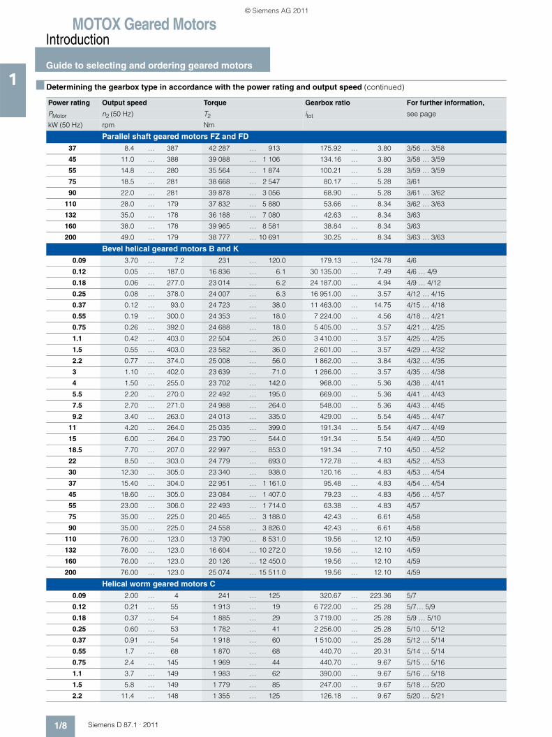
1 ■ Determining the gearbox type in accordance with the power rating and output speed (continued)
Power rating Output speed Torque Gearbox ratio For further information,
PMotor n2 (50 Hz) T2 itot see page
kW (50 Hz) rpm Nm
Parallel shaft geared motors FZ and FD37 8.4 … 387 42 287 … 913 175.92 … 3.80 3/56 … 3/58
45 11.0 … 388 39 088 … 1 106 134.16 … 3.80 3/58 … 3/59
55 14.8 … 280 35 564 … 1 874 100.21 … 5.28 3/59 … 3/59
75 18.5 … 281 38 668 … 2 547 80.17 … 5.28 3/61
90 22.0 … 281 39 878 … 3 056 68.90 … 5.28 3/61 … 3/62
110 28.0 … 179 37 832 … 5 880 53.66 … 8.34 3/62 … 3/63
132 35.0 … 178 36 188 … 7 080 42.63 … 8.34 3/63
160 38.0 … 178 39 965 … 8 581 38.84 … 8.34 3/63
200 49.0 … 179 38 777 … 10 691 30.25 … 8.34 3/63 … 3/63
Bevel helical geared motors B and K0.09 3.70 … 7.2 231 … 120.0 179.13 … 124.78 4/6
0.12 0.05 … 187.0 16 836 … 6.1 30 135.00 … 7.49 4/6 … 4/9
0.18 0.06 … 277.0 23 014 … 6.2 24 187.00 … 4.94 4/9 … 4/12
0.25 0.08 … 378.0 24 007 … 6.3 16 951.00 … 3.57 4/12 … 4/15
0.37 0.12 … 93.0 24 723 … 38.0 11 463.00 … 14.75 4/15 … 4/18
0.55 0.19 … 300.0 24 353 … 18.0 7 224.00 … 4.56 4/18 … 4/21
0.75 0.26 … 392.0 24 688 … 18.0 5 405.00 … 3.57 4/21 … 4/25
1.1 0.42 … 403.0 22 504 … 26.0 3 410.00 … 3.57 4/25 … 4/25
1.5 0.55 … 403.0 23 582 … 36.0 2 601.00 … 3.57 4/29 … 4/32
2.2 0.77 … 374.0 25 008 … 56.0 1 862.00 … 3.84 4/32 … 4/35
3 1.10 … 402.0 23 639 … 71.0 1 286.00 … 3.57 4/35 … 4/38
4 1.50 … 255.0 23 702 … 142.0 968.00 … 5.36 4/38 … 4/41
5.5 2.20 … 270.0 22 492 … 195.0 669.00 … 5.36 4/41 … 4/43
7.5 2.70 … 271.0 24 988 … 264.0 548.00 … 5.36 4/43 … 4/45
9.2 3.40 … 263.0 24 013 … 335.0 429.00 … 5.54 4/45 … 4/47
11 4.20 … 264.0 25 035 … 399.0 191.34 … 5.54 4/47 … 4/49
15 6.00 … 264.0 23 790 … 544.0 191.34 … 5.54 4/49 … 4/50
18.5 7.70 … 207.0 22 997 … 853.0 191.34 … 7.10 4/50 … 4/52
22 8.50 … 303.0 24 779 … 693.0 172.78 … 4.83 4/52 … 4/53
30 12.30 … 305.0 23 340 … 938.0 120.16 … 4.83 4/53 … 4/54
37 15.40 … 304.0 22 951 … 1 161.0 95.48 … 4.83 4/54 … 4/54
45 18.60 … 305.0 23 084 … 1 407.0 79.23 … 4.83 4/56 … 4/57
55 23.00 … 306.0 22 493 … 1 714.0 63.38 … 4.83 4/57
75 35.00 … 225.0 20 465 … 3 188.0 42.43 … 6.61 4/58
90 35.00 … 225.0 24 558 … 3 826.0 42.43 … 6.61 4/58
110 76.00 … 123.0 13 790 … 8 531.0 19.56 … 12.10 4/59
132 76.00 … 123.0 16 604 … 10 272.0 19.56 … 12.10 4/59
160 76.00 … 123.0 20 126 … 12 450.0 19.56 … 12.10 4/59
200 76.00 … 123.0 25 074 … 15 511.0 19.56 … 12.10 4/59
Helical worm geared motors C0.09 2.00 … 4 241 … 125 320.67 … 223.36 5/7
0.12 0.21 … 55 1 913 … 19 6 722.00 … 25.28 5/7… 5/9
0.18 0.37 … 54 1 885 … 29 3 719.00 … 25.28 5/9 … 5/10
0.25 0.60 … 53 1 782 … 41 2 256.00 … 25.28 5/10 … 5/12
0.37 0.91 … 54 1 918 … 60 1 510.00 … 25.28 5/12 … 5/14
0.55 1.7 … 68 1 870 … 68 440.70 … 20.31 5/14 … 5/14
0.75 2.4 … 145 1 969 … 44 440.70 … 9.67 5/15 … 5/16
1.1 3.7 … 149 1 983 … 62 390.00 … 9.67 5/16 … 5/18
1.5 5.8 … 149 1 779 … 85 247.00 … 9.67 5/18 … 5/20
2.2 11.4 … 148 1 355 … 125 126.18 … 9.67 5/20 … 5/21
© Siemens AG 2011
MOTOX Geared MotorsIntroduction
Guide to selecting and ordering geared motors
1/9Siemens D 87.1 · 2011
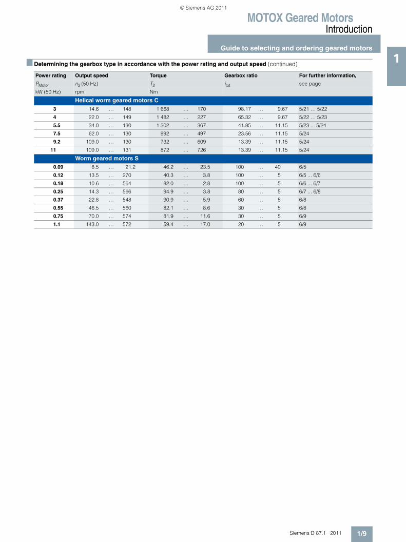
1
Helical worm geared motors C3 14.6 … 148 1 668 … 170 98.17 … 9.67 5/21 … 5/22
4 22.0 … 149 1 482 … 227 65.32 … 9.67 5/22 … 5/23
5.5 34.0 … 130 1 302 … 367 41.85 … 11.15 5/23 ... 5/24
7.5 62.0 … 130 992 … 497 23.56 … 11.15 5/24
9.2 109.0 … 130 732 … 609 13.39 … 11.15 5/24
11 109.0 … 131 872 … 726 13.39 … 11.15 5/24
Worm geared motors S0.09 8.5 … 21.2 46.2 … 23.5 100 … 40 6/5
0.12 13.5 … 270 40.3 … 3.8 100 … 5 6/5 ... 6/6
0.18 10.6 … 564 82.0 … 2.8 100 … 5 6/6 ... 6/7
0.25 14.3 … 566 94.9 … 3.8 80 … 5 6/7 ... 6/8
0.37 22.8 … 548 90.9 … 5.9 60 … 5 6/8
0.55 46.5 … 560 82.1 … 8.6 30 … 5 6/8
0.75 70.0 … 574 81.9 … 11.6 30 … 5 6/9
1.1 143.0 … 572 59.4 … 17.0 20 … 5 6/9
■ Determining the gearbox type in accordance with the power rating and output speed (continued)
Power rating Output speed Torque Gearbox ratio For further information,
PMotor n2 (50 Hz) T2 itot see page
kW (50 Hz) rpm Nm
© Siemens AG 2011
MOTOX Geared MotorsIntroduction
Guide to selecting and ordering geared motors
1/10 Siemens D 87.1 · 2011
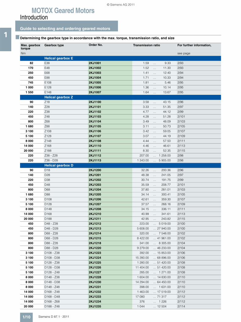
1 ■ Determining the gearbox type in accordance with the max. torque, transmission ratio, and size
Max. gearbox torque
Gearbox type Order No. Transmission ratio For further information,
Nm see page
Helical gearbox E82 E38 2KJ1001 1.59 … 9.33 2/93
170 E48 2KJ1002 1.52 … 11.30 2/93
250 E68 2KJ1003 1.41 … 12.40 2/94
450 E88 2KJ1004 1.71 … 10.33 2/94
745 E108 2KJ1005 1.81 … 5.46 2/95
1 000 E128 2KJ1006 1.36 … 10.14 2/95
1 550 E148 2KJ1007 1.64 … 13.67 2/95
Helical gearbox Z90 Z18 2KJ1100 3.58 … 43.15 2/96
140 Z28 2KJ1101 3.33 … 51.35 2/97
220 Z38 2KJ1102 4.77 … 44.12 2/99
450 Z48 2KJ1103 4.28 … 51.28 2/101
800 Z68 2KJ1104 3.49 … 48.09 2/103
1 680 Z88 2KJ1105 3.11 … 50.73 2/105
3 100 Z108 2KJ1106 3.42 … 59.05 2/107
5 100 Z128 2KJ1107 3.07 … 44.19 2/109
8 000 Z148 2KJ1108 4.44 … 57.50 2/111
14 000 Z168 2KJ1110 4.46 … 46.61 2/113
20 000 Z188 2KJ1111 8.30 … 52.35 2/115
220 Z38 - Z28 2KJ1112 207.00 … 1 258.00 2/98
220 Z38 - D28 2KJ1113 1 343.00 … 5 905.00 2/98
Helical gearbox D90 D18 2KJ1200 32.26 … 200.36 2/96
140 D28 2KJ1201 48.38 … 241.05 2/97
220 D38 2KJ1202 30.74 … 191.75 2/99
450 D48 2KJ1203 35.59 … 208.77 2/101
800 D68 2KJ1204 37.80 … 281.01 2/103
1 680 D88 2KJ1205 34.14 … 300.41 2/105
3 100 D108 2KJ1206 42.61 … 359.30 2/107
5 100 D128 2KJ1207 37.57 … 268.16 2/109
8 000 D148 2KJ1208 34.15 … 336.11 2/111
14 000 D168 2KJ1210 40.99 … 341.61 2/113
20 000 D188 2KJ1211 42.95 … 243.82 2/115
450 D48 - Z28 2KJ1212 223.00 … 5 019.00 2/100
450 D48 - D28 2KJ1213 5 608.00 … 27 940.00 2/100
800 D68 - Z28 2KJ1214 320.00 … 7 548.00 2/102
800 D68 - D28 2KJ1215 8 422.00 … 41 961.00 2/102
800 D88 - Z28 2KJ1218 341.00 … 8 305.00 2/104
800 D88 - D28 2KJ1220 9 279.00 … 46 233.00 2/104
3 100 D108 - Z38 2KJ1223 392.00 … 15 853.00 2/106
3 100 D108 - D38 2KJ1224 15 280.00 … 68 896.00 2/106
5 100 D128 - Z38 2KJ1225 1 280.00 … 51 420.00 2/108
5 100 D128 - D38 2KJ1226 11 404.00 … 51 420.00 2/108
5 100 D128 - Z48 2KJ1227 285.00 … 1 271.00 2/108
8 000 D148 - Z38 2KJ1228 1 604.00 … 14 830.00 2/110
8 000 D148 - D38 2KJ1230 14 294.00 … 64 450.00 2/110
8 000 D148 - Z48 2KJ1231 398.00 … 1 631.00 2/110
14 000 D168 - Z48 2KJ1232 1 463.00 … 17 519.00 2/112
14 000 D168 - D48 2KJ1233 17 080 … 71 317 2/112
14 000 D168 - Z68 2KJ1234 376 … 1 226 2/112
20 000 D188 - Z48 2KJ1235 1 044 … 12 504 2/114
© Siemens AG 2011
MOTOX Geared MotorsIntroduction
Guide to selecting and ordering geared motors
1/11Siemens D 87.1 · 2011
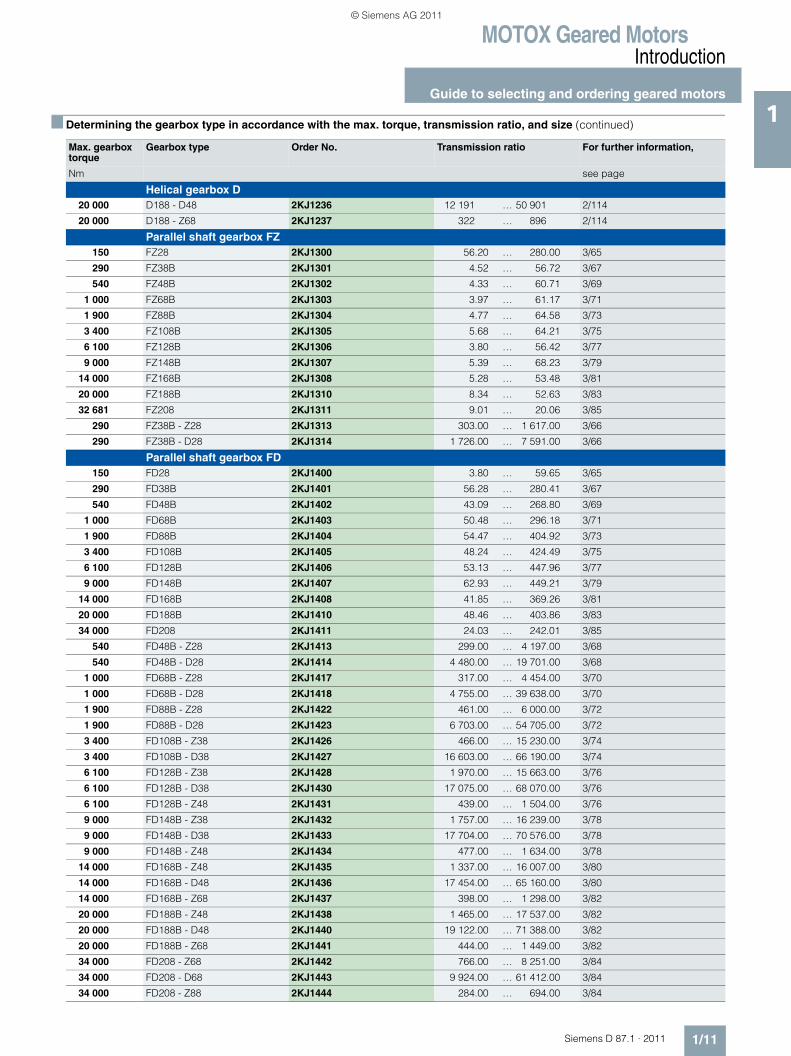
1■ Determining the gearbox type in accordance with the max. torque, transmission ratio, and size (continued)
Max. gearbox torque
Gearbox type Order No. Transmission ratio For further information,
Nm see page
Helical gearbox D20 000 D188 - D48 2KJ1236 12 191 … 50 901 2/114
20 000 D188 - Z68 2KJ1237 322 … 896 2/114
Parallel shaft gearbox FZ150 FZ28 2KJ1300 56.20 … 280.00 3/65
290 FZ38B 2KJ1301 4.52 … 56.72 3/67
540 FZ48B 2KJ1302 4.33 … 60.71 3/69
1 000 FZ68B 2KJ1303 3.97 … 61.17 3/71
1 900 FZ88B 2KJ1304 4.77 … 64.58 3/73
3 400 FZ108B 2KJ1305 5.68 … 64.21 3/75
6 100 FZ128B 2KJ1306 3.80 … 56.42 3/77
9 000 FZ148B 2KJ1307 5.39 … 68.23 3/79
14 000 FZ168B 2KJ1308 5.28 … 53.48 3/81
20 000 FZ188B 2KJ1310 8.34 … 52.63 3/83
32 681 FZ208 2KJ1311 9.01 … 20.06 3/85
290 FZ38B - Z28 2KJ1313 303.00 … 1 617.00 3/66
290 FZ38B - D28 2KJ1314 1 726.00 … 7 591.00 3/66
Parallel shaft gearbox FD150 FD28 2KJ1400 3.80 … 59.65 3/65
290 FD38B 2KJ1401 56.28 … 280.41 3/67
540 FD48B 2KJ1402 43.09 … 268.80 3/69
1 000 FD68B 2KJ1403 50.48 … 296.18 3/71
1 900 FD88B 2KJ1404 54.47 … 404.92 3/73
3 400 FD108B 2KJ1405 48.24 … 424.49 3/75
6 100 FD128B 2KJ1406 53.13 … 447.96 3/77
9 000 FD148B 2KJ1407 62.93 … 449.21 3/79
14 000 FD168B 2KJ1408 41.85 … 369.26 3/81
20 000 FD188B 2KJ1410 48.46 … 403.86 3/83
34 000 FD208 2KJ1411 24.03 … 242.01 3/85
540 FD48B - Z28 2KJ1413 299.00 … 4 197.00 3/68
540 FD48B - D28 2KJ1414 4 480.00 … 19 701.00 3/68
1 000 FD68B - Z28 2KJ1417 317.00 … 4 454.00 3/70
1 000 FD68B - D28 2KJ1418 4 755.00 … 39 638.00 3/70
1 900 FD88B - Z28 2KJ1422 461.00 … 6 000.00 3/72
1 900 FD88B - D28 2KJ1423 6 703.00 … 54 705.00 3/72
3 400 FD108B - Z38 2KJ1426 466.00 … 15 230.00 3/74
3 400 FD108B - D38 2KJ1427 16 603.00 … 66 190.00 3/74
6 100 FD128B - Z38 2KJ1428 1 970.00 … 15 663.00 3/76
6 100 FD128B - D38 2KJ1430 17 075.00 … 68 070.00 3/76
6 100 FD128B - Z48 2KJ1431 439.00 … 1 504.00 3/76
9 000 FD148B - Z38 2KJ1432 1 757.00 … 16 239.00 3/78
9 000 FD148B - D38 2KJ1433 17 704.00 … 70 576.00 3/78
9 000 FD148B - Z48 2KJ1434 477.00 … 1 634.00 3/78
14 000 FD168B - Z48 2KJ1435 1 337.00 … 16 007.00 3/80
14 000 FD168B - D48 2KJ1436 17 454.00 … 65 160.00 3/80
14 000 FD168B - Z68 2KJ1437 398.00 … 1 298.00 3/82
20 000 FD188B - Z48 2KJ1438 1 465.00 … 17 537.00 3/82
20 000 FD188B - D48 2KJ1440 19 122.00 … 71 388.00 3/82
20 000 FD188B - Z68 2KJ1441 444.00 … 1 449.00 3/82
34 000 FD208 - Z68 2KJ1442 766.00 … 8 251.00 3/84
34 000 FD208 - D68 2KJ1443 9 924.00 … 61 412.00 3/84
34 000 FD208 - Z88 2KJ1444 284.00 … 694.00 3/84
© Siemens AG 2011
MOTOX Geared MotorsIntroduction
Guide to selecting and ordering geared motors
1/12 Siemens D 87.1 · 2011
1
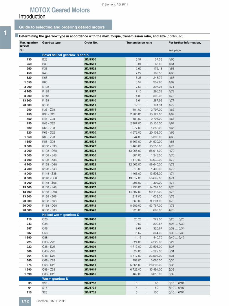
Bevel helical gearbox B and K130 B28 2KJ1500 3.57 … 57.53 4/60
250 B38 2KJ1501 3.84 … 65.69 4/61
250 K38 2KJ1502 5.65 … 179.13 4/63
450 K48 2KJ1503 7.22 … 169.53 4/65
820 K68 2KJ1504 5.36 … 243.72 4/67
1 650 K88 2KJ1505 5.54 … 302.68 4/69
3 000 K108 2KJ1506 7.68 … 307.24 4/71
4 700 K128 2KJ1507 7.10 … 295.38 4/73
8 000 K148 2KJ1508 4.83 … 306.08 4/75
13 500 K168 2KJ1510 6.61 … 287.95 4/77
20 000 K188 2KJ1511 12.10 … 191.34 4/79
250 K38 - Z28 2KJ1514 181.00 … 2 797.00 4/62
250 K38 - D28 2KJ1515 2 986.00 … 13 129.00 4/62
450 K48 - Z28 2KJ1516 181.00 … 2 798.00 4/64
450 K48 - D28 2KJ1517 2 987.00 … 13 135.00 4/64
820 K68 - Z28 2KJ1518 277.00 … 4 282.00 4/66
820 K68 - D28 2KJ1520 4 572.00 … 20 103.00 4/66
1 650 K88 - Z28 2KJ1523 344.00 … 5 309.00 4/68
1 650 K88 - D28 2KJ1524 5 667.00 … 24 920.00 4/68
3 000 K108 - Z38 2KJ1527 1 466.00 … 13 556.00 4/70
3 000 K108 - D38 2KJ1528 13 066.00 … 58 914.00 4/70
3 000 K108 - Z48 2KJ1530 301.00 … 1 343.00 4/70
4 700 K128 - Z38 2KJ1531 1 410.00 … 13 032.00 4/72
4 700 K128 - D38 2KJ1532 12 562.00 … 56 640.00 4/72
4 700 K128 - Z48 2KJ1533 313.00 … 1 400.00 4/72
8 000 K148 - Z38 2KJ1534 1 466.00 … 13 505.00 4/74
8 000 K148 - D38 2KJ1535 13 017.00 … 58 692.00 4/74
8 000 K148 - Z68 2KJ1536 296.00 … 1 392.00 4/74
13 500 K168 - Z48 2KJ1537 1 233.00 … 14 767.00 4/76
13 500 K168 - D48 2KJ1538 14 397.00 … 60 115.00 4/76
13 500 K168 - Z68 2KJ1540 317.00 … 1 033.00 4/76
20 000 K188 - Z68 2KJ1541 669.00 … 9 201.00 4/78
20 000 K188 - D68 2KJ1542 8 689.00 … 53 767.00 4/78
20 000 K188 - Z88 2KJ1543 225.00 … 669.00 4/78
Helical worm gearbox C118 C28 2KJ1600 25.28 … 372.00 5/25 … 5/26
243 C38 2KJ1601 9.67 … 320.67 5/28 … 5/30
387 C48 2KJ1602 9.67 … 320.67 5/32 … 5/34
687 C68 2KJ1603 11.67 … 364.00 5/36 … 5/38
1 590 C88 2KJ1604 11.15 … 440.70 5/40 … 5/42
225 C38 - Z28 2KJ1605 324.00 … 4 222.00 5/27
222 C38 - D28 2KJ1606 4 717.00 … 23 503.00 5/27
369 C48 - Z28 2KJ1607 324.00 … 4 222.00 5/31
364 C48 - D28 2KJ1608 4 717.00 … 23 503.00 5/31
680 C68 - Z28 2KJ1610 398.00 … 5 066.00 5/35
675 C68 - D28 2KJ1611 5 661.00 … 28 203.00 5/35
1 590 C88 - Z28 2KJ1614 6 722.00 … 33 491.00 5/39
1 590 C88 - D28 2KJ1615 462.00 … 6 016.00 5/39
Worm gearbox S33 S08 2KJ1730 5 … 80 6/10 ... 6/10
64 S18 2KJ1731 5 … 80 6/10 ... 6/10
116 S28 2KJ1732 5 … 100 6/10 ... 6/10
■ Determining the gearbox type in accordance with the max. torque, transmission ratio, and size (continued)
Max. gearbox torque
Gearbox type Order No. Transmission ratio For further information,
Nm see page
© Siemens AG 2011
MOTOX Geared MotorsIntroduction
Guide to selecting and ordering geared motors
1/13Siemens D 87.1 · 2011
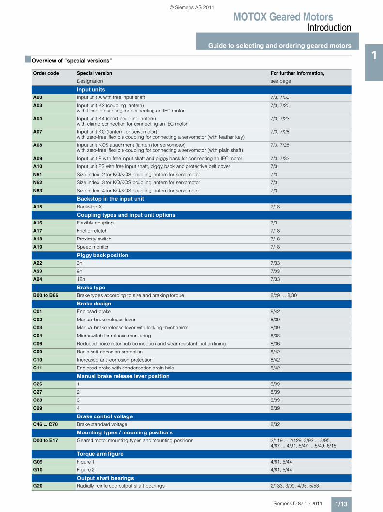
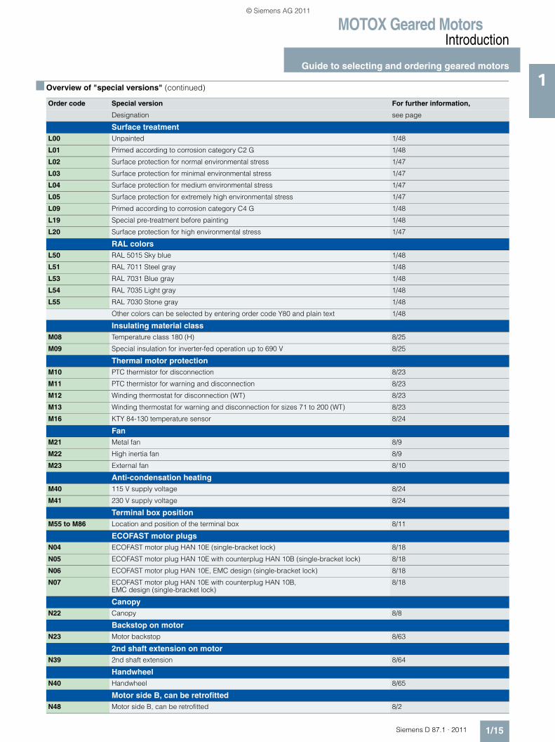
1■ Overview of "special versions"
Order code Special version For further information,
Designation see page
Input unitsA00 Input unit A with free input shaft 7/3, 7/30
A03 Input unit K2 (coupling lantern) with flexible coupling for connecting an IEC motor
7/3, 7/20
A04 Input unit K4 (short coupling lantern) with clamp connection for connecting an IEC motor
7/3, 7/23
A07 Input unit KQ (lantern for servomotor) with zero-free, flexible coupling for connecting a servomotor (with feather key)
7/3, 7/28
A08 Input unit KQS attachment (lantern for servomotor) with zero-free, flexible coupling for connecting a servomotor (with plain shaft)
7/3, 7/28
A09 Input unit P with free input shaft and piggy back for connecting an IEC motor 7/3, 7/33
A10 Input unit PS with free input shaft, piggy back and protective belt cover 7/3
N61 Size index .2 for KQ/KQS coupling lantern for servomotor 7/3
N62 Size index .3 for KQ/KQS coupling lantern for servomotor 7/3
N63 Size index .4 for KQ/KQS coupling lantern for servomotor 7/3
Backstop in the input unitA15 Backstop X 7/18
Coupling types and input unit optionsA16 Flexible coupling 7/3
A17 Friction clutch 7/18
A18 Proximity switch 7/18
A19 Speed monitor 7/18
Piggy back positionA22 3h 7/33
A23 9h 7/33
A24 12h 7/33
Brake typeB00 to B66 Brake types according to size and braking torque 8/29 … 8/30
Brake designC01 Enclosed brake 8/42
C02 Manual brake release lever 8/39
C03 Manual brake release lever with locking mechanism 8/39
C04 Microswitch for release monitoring 8/38
C06 Reduced-noise rotor-hub connection and wear-resistant friction lining 8/36
C09 Basic anti-corrosion protection 8/42
C10 Increased anti-corrosion protection 8/42
C11 Enclosed brake with condensation drain hole 8/42
Manual brake release lever positionC26 1 8/39
C27 2 8/39
C28 3 8/39
C29 4 8/39
Brake control voltageC46 ... C70 Brake standard voltage 8/32
Mounting types / mounting positionsD00 to E17 Geared motor mounting types and mounting positions 2/119 ... 2/129, 3/92 ... 3/95,
4/87 ... 4/91, 5/47 ... 5/49, 6/15
Torque arm figureG09 Figure 1 4/81, 5/44
G10 Figure 2 4/81, 5/44
Output shaft bearingsG20 Radially reinforced output shaft bearings 2/133, 3/99, 4/95, 5/53
© Siemens AG 2011
MOTOX Geared MotorsIntroduction
Guide to selecting and ordering geared motors
1/14 Siemens D 87.1 · 2011
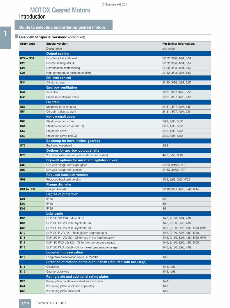
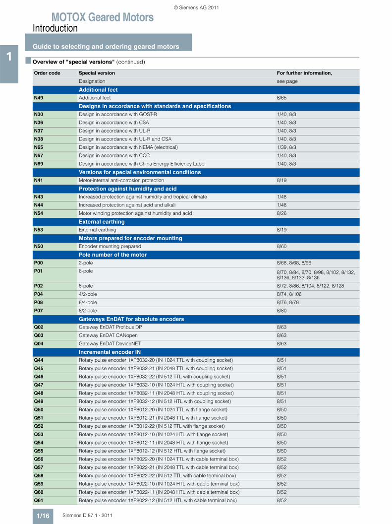
1■ Overview of "special versions" (continued)
Order code Special version For further information,
Designation see page
Output sealingG22 + G31 Double radial shaft seal 2/132, 3/98, 4/94, 5/52
G23 Double sealing MSS1 2/132, 3/98, 4/94, 5/52
G24 Combination shaft sealing 2/132, 3/98, 4/94, 5/52
G25 High temperature resistant sealing 2/132, 3/98, 4/94, 5/52
Oil level controlG34 Oil sight glass 2/130, 3/96, 4/93, 5/50
Gearbox ventilationG44 Vent filter 2/131, 3/97, 4/93, 5/51
G45 Pressure ventilation valve 2/131, 3/97, 4/93, 5/51
Oil drainG53 Magnetic oil drain plug 2/131, 3/97, 4/94, 5/51
G54 Oil drain valve, straight 2/131, 3/97, 4/94, 5/51
Hollow-shaft coverG60 Steel protection cover 3/99, 4/95, 5/52
G61 Steel protection cover (ATEX) 3/99, 4/95, 5/52
G62 Protection cover 3/99, 4/95, 5/52
G63 Protection cover (ATEX) 3/99, 4/95, 5/52
Backstop for bevel helical gearboxG72 Backstop (gearbox) 4/96
Options for gearbox output shaftsG73 2nd shaft extension (output shaft on both sides) 4/96, 5/53, 6/16
Dry-well options for mixer and agitator drivesG89 Dry-well design with sight glass 2/133, 3/100, 4/97
G90 Dry-well design with sensor 2/133, 3/100, 4/97
Reduced-backlash versionG99 Reduced-backlash version 1/23, 2/93, 3/65, 4/62
Flange diameterH01 to H06 Flange diameter 2/118, 3/91, 4/86, 5/46, 6/14
Degree of protectionK01 IP 55 8/8
K02 IP 56 8/8
K03 IP 65 8/8
LubricantsK06 CLP ISO VG 220 - Mineral oil 1/46, 2/130, 3/94, 4/92
K07 CLP ISO PG VG 220 - Synthetic oil 1/46, 2/130, 3/96, 4/92
K08 CLP ISO PG VG 460 - Synthetic oil 1/46, 2/130, 3/96, 4/92, 5/50, 6/16
K10 CLP ISO E VG 220 - Biologically degradable oil 1/46, 2/130, 3/96, 4/92, 5/50
K11 CLP ISO H1 VG 460 - Oil for use in the food industry 1/46, 2/130, 3/96, 4/92, 5/50, 6/16
K12 CLP ISO PAO VG 220 - Oil for low temperature usage 1/46, 2/130, 3/96, 4/92, 5/50
K13 CLP ISO PAO VG 68 - Oil for lowest temperature usage 1/46, 2/130, 3/96, 4/92
Long-term preservationK17 Long-term preservation up to 36 months 1/46
Direction of rotation of the output shaft (required with backstop)K18 Clockwise 1/43, 4/96
K19 Counterclockwise 1/43, 4/96
Rating plate and additional rating platesK26 Rating plate on stainless steel support plate 1/49
K41 2nd rating plate, enclosed separately 1/49
K68 2nd rating plate, mounted 1/49
© Siemens AG 2011
MOTOX Geared MotorsIntroduction
Guide to selecting and ordering geared motors
1/15Siemens D 87.1 · 2011
1
Surface treatmentL00 Unpainted 1/48
L01 Primed according to corrosion category C2 G 1/48
L02 Surface protection for normal environmental stress 1/47
L03 Surface protection for minimal environmental stress 1/47
L04 Surface protection for medium environmental stress 1/47
L05 Surface protection for extremely high environmental stress 1/47
L09 Primed according to corrosion category C4 G 1/48
L19 Special pre-treatment before painting 1/48
L20 Surface protection for high environmental stress 1/47
RAL colorsL50 RAL 5015 Sky blue 1/48
L51 RAL 7011 Steel gray 1/48
L53 RAL 7031 Blue gray 1/48
L54 RAL 7035 Light gray 1/48
L55 RAL 7030 Stone gray 1/48
Other colors can be selected by entering order code Y80 and plain text 1/48
Insulating material classM08 Temperature class 180 (H) 8/25
M09 Special insulation for inverter-fed operation up to 690 V 8/25
Thermal motor protectionM10 PTC thermistor for disconnection 8/23
M11 PTC thermistor for warning and disconnection 8/23
M12 Winding thermostat for disconnection (WT) 8/23
M13 Winding thermostat for warning and disconnection for sizes 71 to 200 (WT) 8/23
M16 KTY 84-130 temperature sensor 8/24
FanM21 Metal fan 8/9
M22 High inertia fan 8/9
M23 External fan 8/10
Anti-condensation heatingM40 115 V supply voltage 8/24
M41 230 V supply voltage 8/24
Terminal box positionM55 to M86 Location and position of the terminal box 8/11
ECOFAST motor plugsN04 ECOFAST motor plug HAN 10E (single-bracket lock) 8/18
N05 ECOFAST motor plug HAN 10E with counterplug HAN 10B (single-bracket lock) 8/18
N06 ECOFAST motor plug HAN 10E, EMC design (single-bracket lock) 8/18
N07 ECOFAST motor plug HAN 10E with counterplug HAN 10B, EMC design (single-bracket lock)
8/18
CanopyN22 Canopy 8/8
Backstop on motorN23 Motor backstop 8/63
2nd shaft extension on motorN39 2nd shaft extension 8/64
HandwheelN40 Handwheel 8/65
Motor side B, can be retrofittedN48 Motor side B, can be retrofitted 8/2
■ Overview of "special versions" (continued)
Order code Special version For further information,
Designation see page
© Siemens AG 2011
MOTOX Geared MotorsIntroduction
Guide to selecting and ordering geared motors
1/16 Siemens D 87.1 · 2011
1
Additional feetN49 Additional feet 8/65
Designs in accordance with standards and specificationsN30 Design in accordance with GOST-R 1/40, 8/3
N36 Design in accordance with CSA 1/40, 8/3
N37 Design in accordance with UL-R 1/40, 8/3
N38 Design in accordance with UL-R and CSA 1/40, 8/3
N65 Design in accordance with NEMA (electrical) 1/39, 8/3
N67 Design in accordance with CCC 1/40, 8/3
N69 Design in accordance with China Energy Efficiency Label 1/40, 8/3
Versions for special environmental conditionsN41 Motor-internal anti-corrosion protection 8/19
Protection against humidity and acidN43 Increased protection against humidity and tropical climate 1/48
N44 Increased protection against acid and alkali 1/48
N54 Motor winding protection against humidity and acid 8/26
External earthingN53 External earthing 8/19
Motors prepared for encoder mountingN50 Encoder mounting prepared 8/60
Pole number of the motorP00 2-pole 8/68, 8/68, 8/96
P01 6-pole 8/70, 8/84, 8/70, 8/98, 8/102, 8/132, 8/136, 8/132, 8/136
P02 8-pole 8/72, 8/86, 8/104, 8/122, 8/128
P04 4/2-pole 8/74, 8/106
P08 8/4-pole 8/76, 8/78
P07 8/2-pole 8/80
Gateways EnDAT for absolute encodersQ02 Gateway EnDAT Profibus DP 8/63
Q03 Gateway EnDAT CANopen 8/63
Q04 Gateway EnDAT DeviceNET 8/63
Incremental encoder INQ44 Rotary pulse encoder 1XP8032-20 (IN 1024 TTL with coupling socket) 8/51
Q45 Rotary pulse encoder 1XP8032-21 (IN 2048 TTL with coupling socket) 8/51
Q46 Rotary pulse encoder 1XP8032-22 (IN 512 TTL with coupling socket) 8/51
Q47 Rotary pulse encoder 1XP8032-10 (IN 1024 HTL with coupling socket) 8/51
Q48 Rotary pulse encoder 1XP8032-11 (IN 2048 HTL with coupling socket) 8/51
Q49 Rotary pulse encoder 1XP8032-12 (IN 512 HTL with coupling socket) 8/51
Q50 Rotary pulse encoder 1XP8012-20 (IN 1024 TTL with flange socket) 8/50
Q51 Rotary pulse encoder 1XP8012-21 (IN 2048 TTL with flange socket) 8/50
Q52 Rotary pulse encoder 1XP8012-22 (IN 512 TTL with flange socket) 8/50
Q53 Rotary pulse encoder 1XP8012-10 (IN 1024 HTL with flange socket) 8/50
Q54 Rotary pulse encoder 1XP8012-11 (IN 2048 HTL with flange socket) 8/50
Q55 Rotary pulse encoder 1XP8012-12 (IN 512 HTL with flange socket) 8/50
Q56 Rotary pulse encoder 1XP8022-20 (IN 1024 TTL with cable terminal box) 8/52
Q57 Rotary pulse encoder 1XP8022-21 (IN 2048 TTL with cable terminal box) 8/52
Q58 Rotary pulse encoder 1XP8022-22 (IN 512 TTL with cable terminal box) 8/52
Q59 Rotary pulse encoder 1XP8022-10 (IN 1024 HTL with cable terminal box) 8/52
Q60 Rotary pulse encoder 1XP8022-11 (IN 2048 HTL with cable terminal box) 8/52
Q61 Rotary pulse encoder 1XP8022-12 (IN 512 HTL with cable terminal box) 8/52
■ Overview of "special versions" (continued)
Order code Special version For further information,
Designation see page
© Siemens AG 2011
MOTOX Geared MotorsIntroduction
Guide to selecting and ordering geared motors
1/17Siemens D 87.1 · 2011
1
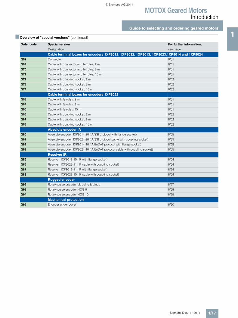
Cable terminal boxes for encoders 1XP8012, 1XP8032, 1XP8013, 1XP8023.1XP8014 and 1XP8024Q62 Connector 8/61
Q69 Cable with connector and ferrules, 2 m 8/61
Q70 Cable with connector and ferrules, 8 m 8/61
Q71 Cable with connector and ferrules, 15 m 8/61
Q72 Cable with coupling socket, 2 m 8/62
Q73 Cable with coupling socket, 8 m 8/62
Q74 Cable with coupling socket, 15 m 8/62
Cable terminal boxes for encoders 1XP8022Q63 Cable with ferrules, 2 m 8/61
Q64 Cable with ferrules, 8 m 8/61
Q65 Cable with ferrules, 15 m 8/61
Q66 Cable with coupling socket, 2 m 8/62
Q67 Cable with coupling socket, 8 m 8/62
Q68 Cable with coupling socket, 15 m 8/62
Absolute encoder IAQ80 Absolute encoder 1XP8014-20 (IA SSI protocol with flange socket) 8/55
Q81 Absolute encoder 1XP8024-20 (IA SSI protocol cable with coupling socket) 8/55
Q82 Absolute encoder 1XP8014-10 (IA EnDAT protocol with flange socket) 8/55
Q83 Absolute encoder 1XP8024-10 (IA EnDAT protocol cable with coupling socket) 8/55
Resolver IRQ85 Resolver 1XP8013-10 (IR with flange socket) 8/54
Q86 Resolver 1XP8023-11 (IR cable with coupling socket) 8/54
Q87 Resolver 1XP8013-11 (IR with flange socket) 8/54
Q88 Resolver 1XP8023-10 (IR cable with coupling socket) 8/54
Rugged encoderQ92 Rotary pulse encoder LL Leine & Linde 8/57
Q93 Rotary pulse encoder HOG 9 8/58
Q94 Rotary pulse encoder HOG 10 8/59
Mechanical protectionQ95 Encoder under cover 8/60
■ Overview of "special versions" (continued)
Order code Special version For further information,
Designation see page
© Siemens AG 2011
MOTOX Geared MotorsIntroduction
Configuring guide
1/18 Siemens D 87.1 · 2011
1 ■ Determining the drive data
Data relating to the machine to be driven (machine type, mass, input speed, speed range, etc.) is required in order to size the machine correctly. This data is then used to determine the required power rating, torque, and input speed of the geared motor. The correct drive can be selected based on its calculated power rating and speed.
Data required for selection
The following data is required in order to select the correct gearbox:
1. Type of driven machine
2. Daily operating time h
3. Required input power kW or required torque Nm
4. Required output speed n2 of the geared motor rpm or gearbox ratio i
5. Operating voltage V and frequency Hz
6. Operating mode, number of startings, inverter-fed operation, type of startup
7. Moment of inertia JLoad kgm2 of the driving machine reduced to the motor shaft
8. Type of power transmission on gearbox shafts (direct, coupling, belt, chain, gear wheel)
9. Radial force Fr N at the input shaft and direction of force with distance from the shaft shoulder to the point of ap-plication and axial force Fax [N] with direction of force
10. Ambient temperature °C
11. Degree of protection
12. Mounting position
13. Required braking torque Nm
14. Any regulations (CSA, VIK, etc.)
© Siemens AG 2011
MOTOX Geared MotorsIntroduction
Configuring guide
1/19Siemens D 87.1 · 2011
1■ Efficiency of the geared motor
The efficiency of the gearbox is determined by the gear teeth, rolling-contact bearing friction, and the shaft sealing rings, among other things. The starting efficiency also has to be taken into account, particularly as regards helical worm and worm gearboxes. Efficiency may be impaired at high input speeds, if a relatively large amount of oil is used (depending on mounting position), and during cold operation in low temperature ranges.
Helical, bevel helical, and parallel shaft gearboxes
MOTOX helical, parallel shaft, and bevel helical gearboxes are extremely efficient. As a rule, efficiencies of 98 % (1-stage), 96 % (2-stage), and 94 % (3-stage) can be assumed.
Helical worm and worm gearboxes
The gear teeth of the worm gearboxes lead to high sliding friction losses at high transmission ratios. Therefore, these gear-boxes can be less efficient than other types. The efficiencies of the helical worm and worm gearboxes primarily depend on the transmission ratio in question. With helical worm gearboxes, some of the transmission ratio is realized by the helical gear stage. In this way, higher degrees of efficiency can be achieved. For further information see the chapter dealing with helical worm gearboxes.
Self-locking with worm gearboxes
In respect of restoring torques on worm gearboxes, the effi-ciency is considerably reduced in comparison to standard effi-ciency. The restoring efficiency can be calculated as follows: η ' = 2 - 1/η . At a standard efficiency of η ≤ 0.5, worm gearboxes are usually self-locking, which is determined by the particular lead angle of the worm gear teeth.Self-locking only occurs with certain combinations of MOTOX gearboxes and is not always of benefit, as the associated loss of efficiency is then relatively high, which in turn requires increased motor power.
A worm gearbox is "self-locking while stationary" (static self-locking), if it is not possible to start from stationary when the worm wheel is driving. A worm gearbox is "self-braking while running" (dynamic self-locking), if it is not possible to continue running when the worm wheel is driving while the gearbox is running – that is, if the run-ning gearbox comes to a stop while the worm wheel is driving.
Shocks can neutralize self-locking. A self-locking gearbox is, therefore, no substitute for a brake or backstop. If you want to use the self-locking braking effect for a technical purpose, please contact us.
Run-in phase for helical worm and worm gearboxes
The tooth flanks on new helical worm and worm gearboxes will not yet be fully smoothed, meaning that the friction angle will be greater and efficiency lower during initial operation. The higher the transmission ratio, the more pronounced the effect.
The run-in procedure should take approximately 24 hours of operation at full load. In most cases, the catalog values will then be reached.
Losses of splashing
With certain gearbox mounting positions, the first stage can become completely immersed in the gear lubricant. In the case of large gearboxes with a high input speed, particularly with vertical mounting positions, this may lead to increased losses of splashing, which must not be ignored. Please contact us if you want to use such gearboxes. If at all possible, you should choose horizontal mounting positions in order to keep losses of splashing to a minimum.
© Siemens AG 2011
MOTOX Geared MotorsIntroduction
Configuring guide
1/20 Siemens D 87.1 · 2011
1 ■ Determining the required service factor
The operating conditions are crucial in determining the service factor and for selecting the geared motor. These conditions are taken into account with service factor fB.
The gearbox size or rated gear torque and the resulting service factor are not standardized and depend on the manufacturer.
In standard operation, i.e. with a uniform load provided by the driving machine, small masses to be accelerated, and a low number of startings, the service factor of fB = 1 can be selected.
For different operating conditions see the tables found under "Service factor". If the motor power and the gearbox output speed are known, a gearbox type is selected with a service factor that meets the following condition.
For drives operating under special conditions, e.g. frequent reversing, short-time or intermittent duty, abnormal temperature ratios, reversal braking, extreme or rotating transverse forces on the gear output shaft, etc. please contact us for advice on how to design the drive configuration.
The operating conditions can vary greatly. To determine the service factor, empirical values can be derived from the configuration of other similar applications. The driving machines can be assigned to three load groups according to their shock load. These groups can be assessed by means of their mass acceleration factor (mAF).
In the case of high mass acceleration factors (mAF >10), a large amount of play in the transmission elements, or high transverse forces, unexpected additional loads may arise. Please contact us in such an event.
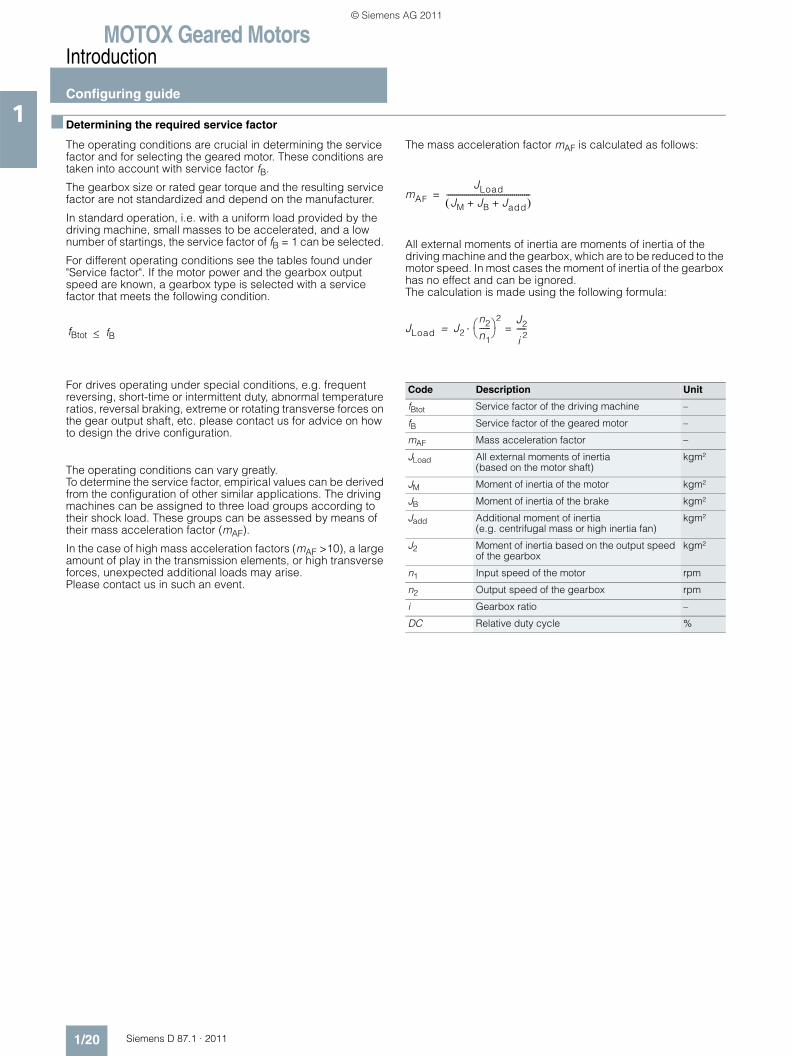
The mass acceleration factor mAF is calculated as follows:
All external moments of inertia are moments of inertia of the driving machine and the gearbox, which are to be reduced to the motor speed. In most cases the moment of inertia of the gearbox has no effect and can be ignored. The calculation is made using the following formula:
fBtot ≤ fB
Code Description Unit
fBtot Service factor of the driving machine –
fB Service factor of the geared motor –
mAF Mass acceleration factor –
JLoad All external moments of inertia (based on the motor shaft)
kgm²
JM Moment of inertia of the motor kgm²
JB Moment of inertia of the brake kgm²
Jadd Additional moment of inertia (e.g. centrifugal mass or high inertia fan)
kgm²
J2 Moment of inertia based on the output speed of the gearbox
kgm²
n1 Input speed of the motor rpm
n2 Output speed of the gearbox rpm
i Gearbox ratio –
DC Relative duty cycle %
mAF
JLoad
JM JB Jadd+ +( )------------------------------------------=
JLoad J2
n2
n1------⎝ ⎠⎛ ⎞
2 J2
i 2-----=⋅=
© Siemens AG 2011
MOTOX Geared MotorsIntroduction
Configuring guide
1/21Siemens D 87.1 · 2011
1■ Required service factor
Service factor for helical, parallel shaft, and bevel helical gearboxes
The service factor of the driving machine fBtot is determined from the tables by taking the load classification, number of startings, and duration of service per day into account. Contact our drive experts to check drive sizing in the case of high shock loads and, for example, high motor and braking torques that are greater than 2.5x the rated motor torque.
Load classification for driving machines
Service factors fB1:
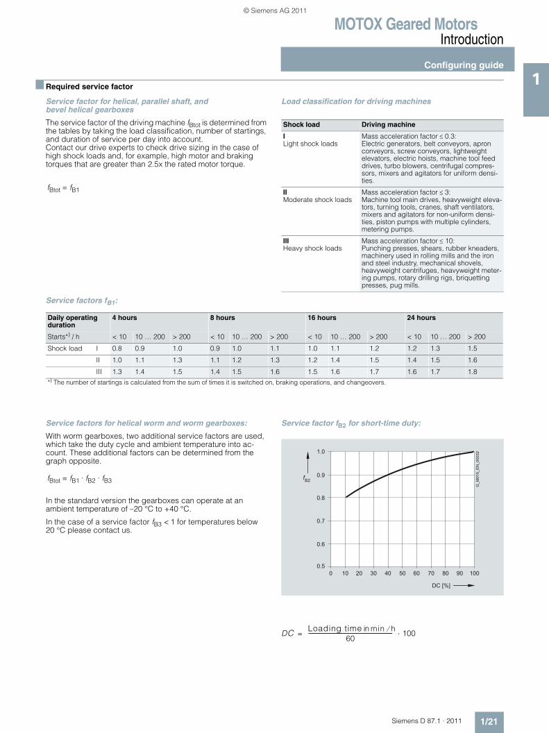
Service factors for helical worm and worm gearboxes:
With worm gearboxes, two additional service factors are used, which take the duty cycle and ambient temperature into ac-count. These additional factors can be determined from the graph opposite.
In the standard version the gearboxes can operate at an ambient temperature of –20 °C to +40 °C.
In the case of a service factor fB3 < 1 for temperatures below 20 °C please contact us.
Service factor fB2 for short-time duty:
fBtot = fB1
Shock load Driving machine
ILight shock loads
Mass acceleration factor ≤ 0.3:Electric generators, belt conveyors, apron conveyors, screw conveyors, lightweight elevators, electric hoists, machine tool feed drives, turbo blowers, centrifugal compres-sors, mixers and agitators for uniform densi-ties.
IIModerate shock loads
Mass acceleration factor ≤ 3:Machine tool main drives, heavyweight eleva-tors, turning tools, cranes, shaft ventilators, mixers and agitators for non-uniform densi-ties, piston pumps with multiple cylinders, metering pumps.
IIIHeavy shock loads
Mass acceleration factor ≤ 10:Punching presses, shears, rubber kneaders, machinery used in rolling mills and the iron and steel industry, mechanical shovels, heavyweight centrifuges, heavyweight meter-ing pumps, rotary drilling rigs, briquetting presses, pug mills.
Daily operating duration
4 hours 8 hours 16 hours 24 hours
Starts*) / h < 10 10 … 200 > 200 < 10 10 … 200 > 200 < 10 10 … 200 > 200 < 10 10 … 200 > 200
Shock load I 0.8 0.9 1.0 0.9 1.0 1.1 1.0 1.1 1.2 1.2 1.3 1.5
II 1.0 1.1 1.3 1.1 1.2 1.3 1.2 1.4 1.5 1.4 1.5 1.6
III 1.3 1.4 1.5 1.4 1.5 1.6 1.5 1.6 1.7 1.6 1.7 1.8
*) The number of startings is calculated from the sum of times it is switched on, braking operations, and changeovers.
fBtot = fB1 · fB2 · fB3
0 10 20 30 40 50 60 70 80 90 100
fB2
1.0
0.9
0.8
0.7
0.6
0.5
G_M
015_
EN
_000
32
DC [%]
DC Loadingttime in min h⁄60
------------------------------------------------------------- 100⋅=
© Siemens AG 2011
MOTOX Geared MotorsIntroduction
Configuring guide
1/22 Siemens D 87.1 · 2011
1 ■ Required service factor (continued)
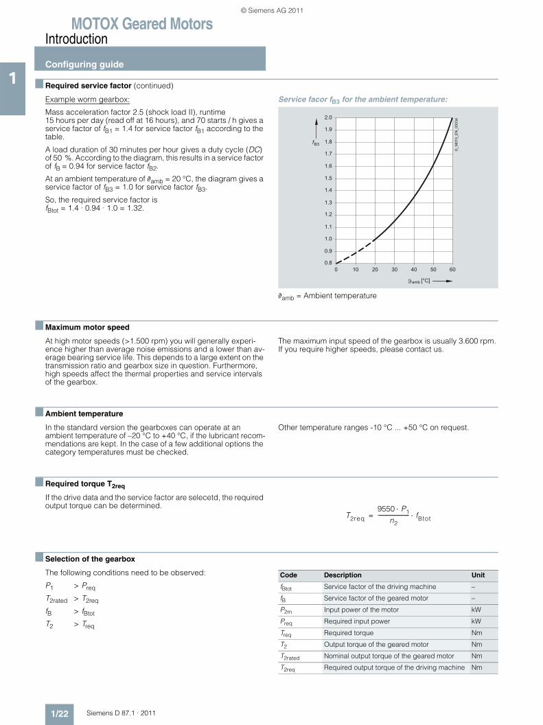
Example worm gearbox:
Mass acceleration factor 2.5 (shock load II), runtime 15 hours per day (read off at 16 hours), and 70 starts / h gives a service factor of fB1 = 1.4 for service factor fB1 according to the table.
A load duration of 30 minutes per hour gives a duty cycle (DC) of 50 %. According to the diagram, this results in a service factor of fB = 0.94 for service factor fB2.
At an ambient temperature of ϑamb = 20 °C, the diagram gives a service factor of fB3 = 1.0 for service factor fB3.
So, the required service factor is fBtot = 1.4 · 0.94 · 1.0 = 1.32.
Service facor fB3 for the ambient temperature:
ϑamb = Ambient temperature
■ Maximum motor speed
At high motor speeds (>1.500 rpm) you will generally experi-ence higher than average noise emissions and a lower than av-erage bearing service life. This depends to a large extent on the transmission ratio and gearbox size in question. Furthermore, high speeds affect the thermal properties and service intervals of the gearbox.
The maximum input speed of the gearbox is usually 3.600 rpm. If you require higher speeds, please contact us.
■ Ambient temperature
In the standard version the gearboxes can operate at an ambient temperature of –20 °C to +40 °C, if the lubricant recom-mendations are kept. In the case of a few additional options the category temperatures must be checked.
Other temperature ranges -10 °C ... +50 °C on request.
■ Required torque T2req
If the drive data and the service factor are selecetd, the required output torque can be determined.
■ Selection of the gearbox
The following conditions need to be observed:
P1 > Preq
T2rated > T2req
fB > fBtot
T2 > Treq
fB3
0 10 20 30 40 50 60
G_M
015_
EN
_000
34
[°C]amb
0.8
0.9
1.0
1.1
1.2
1.3
1.4
1.5
1.6
1.7
1.8
1.9
2.0
T2req9550 P1⋅
n2------------------------ fBtot⋅=
Code Description Unit
fBtot Service factor of the driving machine –
fB Service factor of the geared motor –
P2m Input power of the motor kW
Preq Required input power kW
Treq Required torque Nm
T2 Output torque of the geared motor Nm
T2rated Nominal output torque of the geared motor Nm
T2req Required output torque of the driving machine Nm
© Siemens AG 2011
MOTOX Geared MotorsIntroduction
Configuring guide
1/23Siemens D 87.1 · 2011
1■ Reduced-backlash gearbox version
Helical, parallel shaft and bevel-helical gearboxes are available on request in a reduced-backlash version. In the transmission table, the torsion angle (ϕ) is specified for the reduced-backlash version. If a value is not specified, this gearbox cannot be realized with reduced backlash.
A high degree of positioning accuracy is achieved with reduced-backlash gearboxes and the shock loads in the gearbox are reduced at load changeover. When a gearbox is used that has a certain amount of play, the relative position of the output shaft of the gearbox cannot be determined precisely because the
controller cannot detect whether the right or left flank of the tooth is engaged.• Accurate positioning and repeatability• Maintain position information in the case of a change of
direction of rotation• Reduced shock loading of the tooth flanks
Order code: Reduced-backlash version G99
■ Permissible radial force
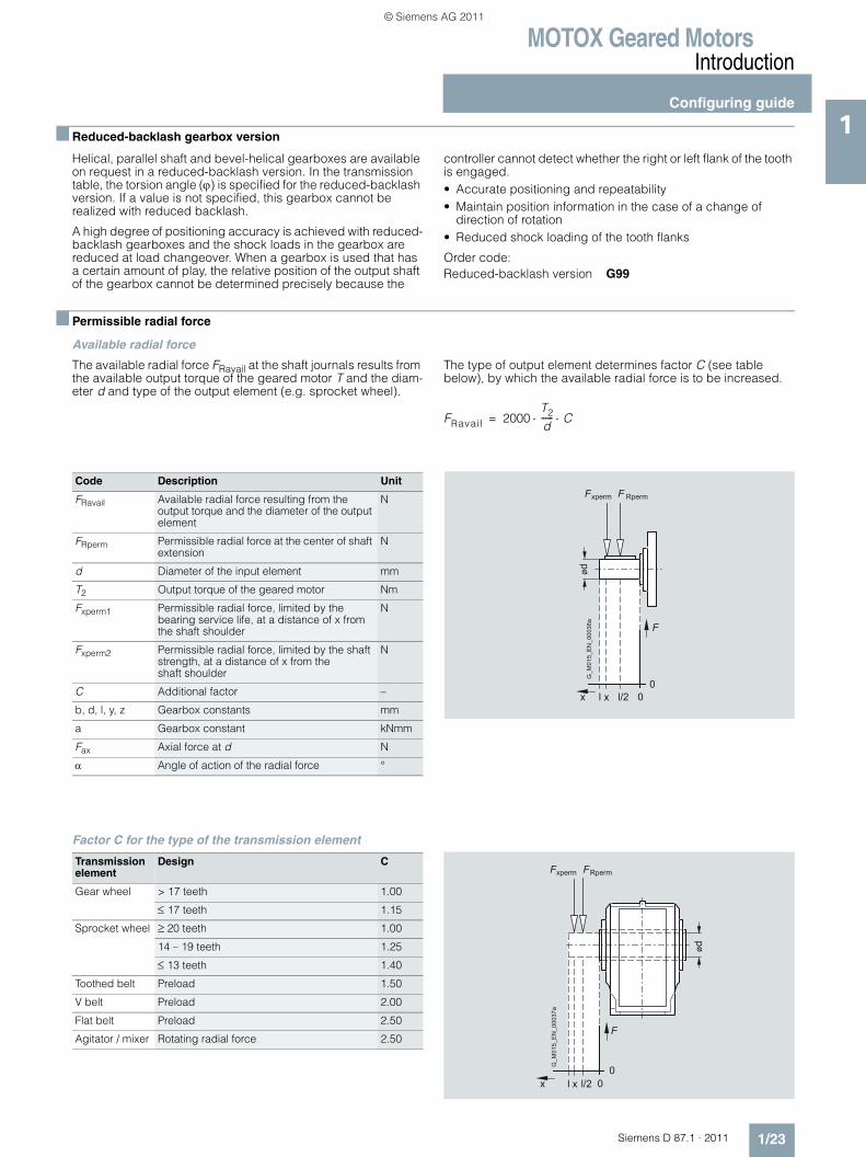
Available radial force
The available radial force FRavail at the shaft journals results from the available output torque of the geared motor T and the diam-eter d and type of the output element (e.g. sprocket wheel).
The type of output element determines factor C (see table below), by which the available radial force is to be increased.
Factor C for the type of the transmission element
FRavail 2000T2
d------ C⋅ ⋅=
Code Description Unit
FRavail Available radial force resulting from the output torque and the diameter of the output element
N
FRperm Permissible radial force at the center of shaft extension
N
d Diameter of the input element mm
T2 Output torque of the geared motor Nm
Fxperm1 Permissible radial force, limited by the bearing service life, at a distance of x from the shaft shoulder
N
Fxperm2 Permissible radial force, limited by the shaft strength, at a distance of x from the shaft shoulder
N
C Additional factor –
b, d, l, y, z Gearbox constants mm
a Gearbox constant kNmm
Fax Axial force at d N
α Angle of action of the radial force °
ød
F
l l/2 00
x x
Fxperm F Rperm
G_M
015_
EN
_000
36a
Transmissionelement
Design C
Gear wheel > 17 teeth 1.00
≤ 17 teeth 1.15
Sprocket wheel ≥ 20 teeth 1.00
14 – 19 teeth 1.25
≤ 13 teeth 1.40
Toothed belt Preload 1.50
V belt Preload 2.00
Flat belt Preload 2.50
Agitator / mixer Rotating radial force 2.50
00
x
F
ød
l l/2x
G_M
015_
EN
_000
37a
xperm FRpermF
© Siemens AG 2011
MOTOX Geared MotorsIntroduction
Configuring guide
1/24 Siemens D 87.1 · 2011
1 ■ Permissible radial force (continued)
Permissible radial force
The permissible radial force FRperm is determined by the required bearing service life, among other things. The nominal service life Lh10 is determined in accordance with ISO 281. The bearing service life can be calculated for special operating conditions on request, based on the calculation procedure for the modified service life Lna.
Furthermore, the permissible radial force is determined by the housing and shaft strength of the gearbox. The selection tables specify the permissible radial force FRperm for the output shafts. These values refer to the point of load at the center of the shaft extension and are minimum values, which apply to the worst possible conditions in the gearbox (force angle, mounting position, direction of rotation).
If the point of load is not at the center of the shaft extension, the permissible radial force must be calculated as follows: the smaller value of Fxperm1 (bearing service life) and Fxperm2 (shaft strength) is the permissible radial force. The calculation does not include additional axial forces.
If the direction of rotation of the output shaft and the additional axial forces are known, or the values in the table are insufficient, our drive experts have to perform the calculation. Our agitator and mixer drives allow you to achieve higher permissible radial forces. These drives are particularly well suited to large and rotating radial forces.
Permissible radial force in accordance with bearing service life for all gearbox types:
Permissible radial force in accordance with shaft strength for helical and worm gearboxes:
Permissible radial force in accordance with shaft strength for bevel helical, parallel shaft, and helical worm gearboxes:
The shaft strength only has to be calculated for solid shafts, with hollow shafts this step can be omitted.
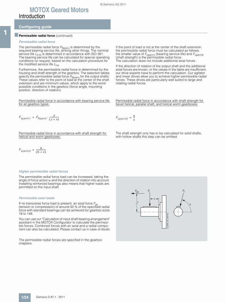
Higher permissible radial forces
The permissible radial force load can be increased, taking the angle of force action α and the direction of rotation into account. Installing reinforced bearings also means that higher loads are permitted on the input shaft.
Permissible axial loads
If no transverse force load is present, an axial force Fax (tension or compression) of around 50 % of the specified radial force with standard bearings can be achieved for gearbox sizes 18 to 148.
You can use our "Calculation of input shaft bearing arrangement" assistant in the MOTOX Configurator to calculate the permissi-ble forces. Combined forces with an axial and a radial compo-nent can also be calculated. Please contact us in case of doubt.
The permissible radial forces are specified in the gearbox chapters.
Fxperm1 FRpermy
z x+( )-----------------⋅=
Fxperm2a
b x+( )------------------=
Fxperm2ax---=
G_D
087_
XX
_000
14a
Fax Fr
l
Fr
x
© Siemens AG 2011
MOTOX Geared MotorsIntroduction
Configuring guide
1/25Siemens D 87.1 · 2011
1■ Determining the operating mode
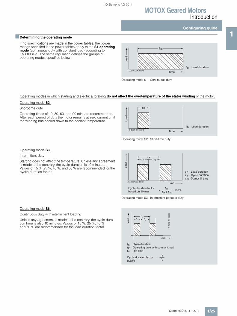
If no specifications are made in the power tables, the power ratings specified in the power tables apply to the S1 operating mode (continuous duty with constant load) according to EN 60034-1. The same regulation defines the groups of operating modes specified below:
Operating mode S1 · Continuous duty
Operating modes in which starting and electrical braking do not affect the overtemperature of the stator winding of the motor:
Operating mode S2:
Short-time duty
Operating times of 10, 30, 60, and 90 min. are recommended. After each period of duty the motor remains at zero current until the winding has cooled down to the coolant temperature.
Operating mode S2 · Short-time duty
Operating mode S3:
Intermittent duty
Starting does not affect the temperature. Unless any agreement is made to the contrary, the cycle duration is 10 minutes. Values of 15 %, 25 %, 40 %, and 60 % are recommended for the cyclic duration factor.
Operating mode S3 · Intermittent periodic duty
Operating mode S6:
Continuous duty with intermittent loading
Unless any agreement is made to the contrary, the cycle dura-tion here is also 10 minutes. Values of 15 %, 25 %, 40 %, and 60 % are recommended for the load duration factor.
G_D087_EN_00018 Time
Load
t B
t B Load duration
G_D087_EN_00019 Time
Load
t B
t B Load duration
G_D087_EN_00020 Time
Load
t B t Stt s
t St Standstill timet s Cycle durationt B Load duration
Cyclic duration factorbased on 10 min
t Bt B t St+= · 100%
tP tVtS
Load
Time
G_D
087_
EN
_000
21
Cycle durationOperating time with constant loadIdle time
tPtV
Cyclic duration factor (CDF)
tP=
tS
tS
© Siemens AG 2011
MOTOX Geared MotorsIntroduction
Configuring guide
1/26 Siemens D 87.1 · 2011
1 ■ Determining the operating mode (continued)
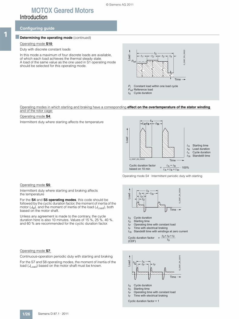
Operating mode S10:
Duty with discrete constant loads
In this mode a maximum of four discrete loads are available, of which each load achieves the thermal steady state. A load of the same value as the one used in S1 operating mode should be selected for this operating mode.
Operating modes in which starting and braking have a corresponding effect on the overtemperature of the stator winding and of the rotor cage:
Operating mode S4:
Intermittent duty where starting affects the temperature
Operating mode S4 · Intermittent periodic duty with starting
Operating mode S5:
Intermittent duty where starting and braking affects the temperature
For the S4 and S5 operating modes, this code should be followed by the cyclic duration factor, the moment of inertia of the motor (JM), and the moment of inertia of the load (JLoad), both based on the motor shaft.
Unless any agreement is made to the contrary, the cycle duration here is also 10 minutes. Values of 15 %, 25 %, 40 %, and 60 % are recommended for the cyclic duration factor.
Operating mode S7:
Continuous-operation periodic duty with starting and braking
For the S7 and S8 operating modes, the moment of inertia of the load (JLoad) based on the motor shaft must be known.
Pref
t1 t2 t3 t4
P 1 P 2 P 3
P 4
tS
Time
Load
G_D
087_
EN
_000
22
PiPref
Constant load within one load cycleReference loadCycle durationtS
t B t Stt s
t A
G_D087_EN_00023 Time
Load
t B t Stt s
t A
t St Standstill timet s Cycle durationt B Load duration
Cyclic duration factor based on 10 min =
t Bt B t St+ · 100%t A +
t A +
t A Starting time
tPtD
Ft tStSt
Cycle durationStarting timeOperating time with constant loadTime with electrical braking
tPtF
Standstill time with windings at zero currentt St
tD
Cyclic duration factor (CDF)
tD=+ tP + tF
tS
tS
Load
Time
G_D
087_
EN
_000
24
tP tFtD tS
Load
Time
G_D
087_
EN
_000
15
Cycle durationStarting timeOperating time with constant loadTime with electrical braking
tPtF
tD
Cyclic duration factor = 1
tS
© Siemens AG 2011
MOTOX Geared MotorsIntroduction
Configuring guide
1/27Siemens D 87.1 · 2011
1■ Determining the operating mode (continued)
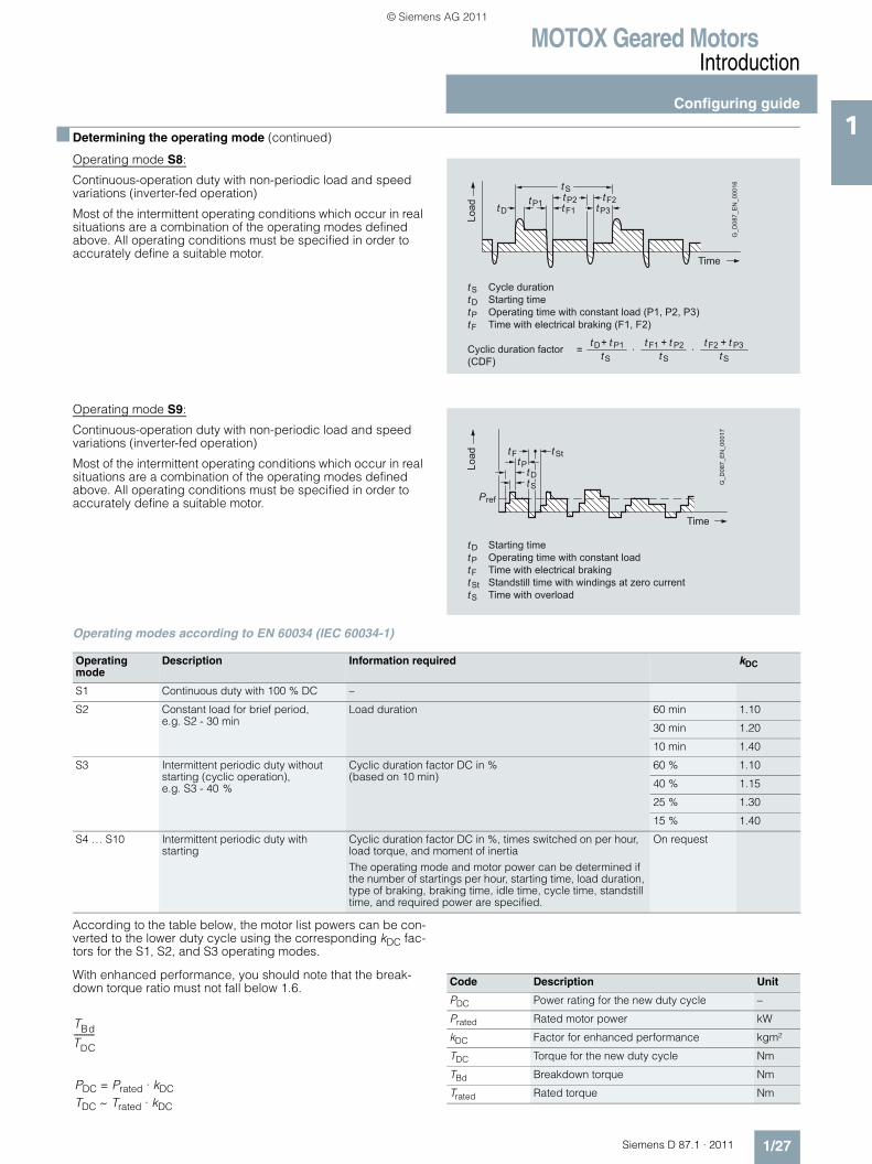
Operating mode S8:
Continuous-operation duty with non-periodic load and speed variations (inverter-fed operation)
Most of the intermittent operating conditions which occur in real situations are a combination of the operating modes defined above. All operating conditions must be specified in order to accurately define a suitable motor.
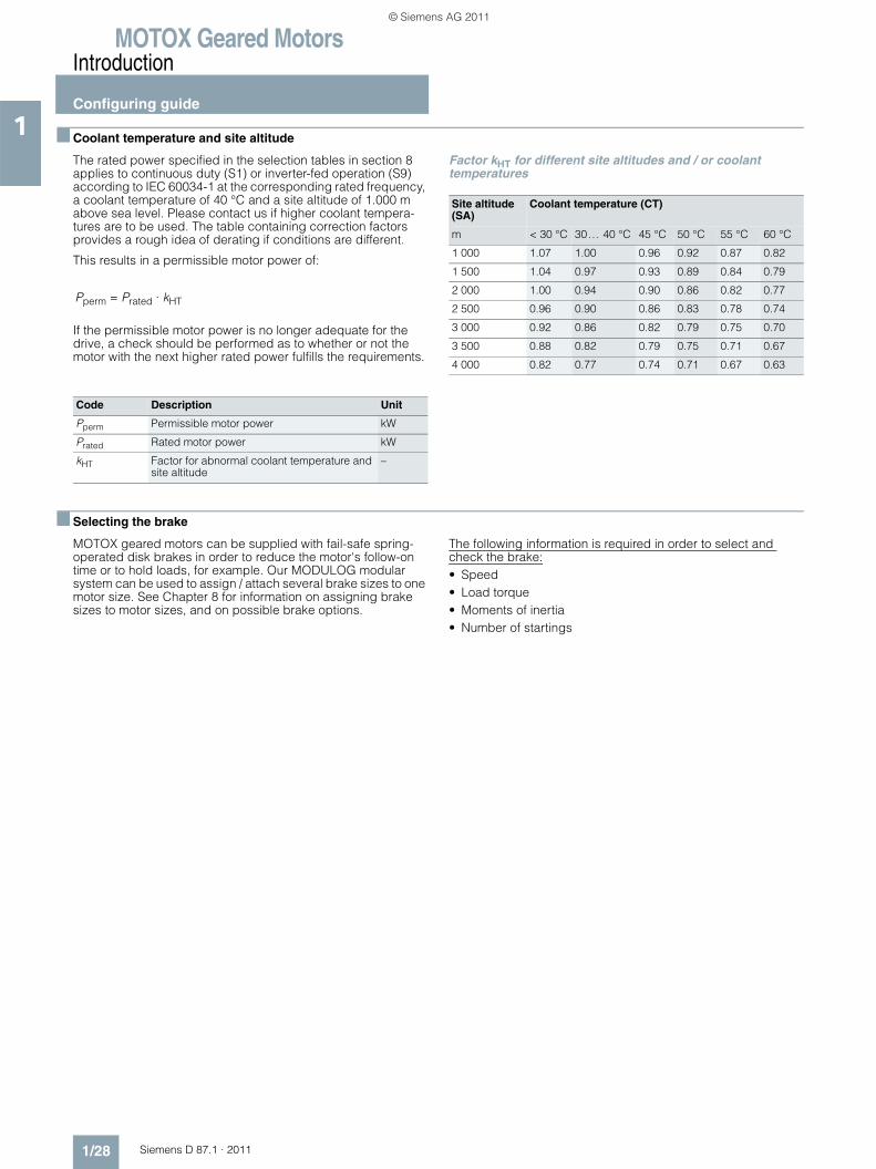
Operating mode S9:
Continuous-operation duty with non-periodic load and speed variations (inverter-fed operation)
Most of the intermittent operating conditions which occur in real situations are a combination of the operating modes defined above. All operating conditions must be specified in order to accurately define a suitable motor.
Operating modes according to EN 60034 (IEC 60034-1)
According to the table below, the motor list powers can be con-verted to the lower duty cycle using the corresponding kDC fac-tors for the S1, S2, and S3 operating modes.
With enhanced performance, you should note that the break-down torque ratio must not fall below 1.6.
tP1tD tF1tP2 tF2
tP3
tS
Load
Time
G_D
087_
EN
_000
16
Cycle durationStarting timeOperating time with constant load (P1, P2, P3)Time with electrical braking (F1, F2)
tPtF
tD
Cyclic duration factor (CDF)
tD=+ t P1 t F1·
+ t P2 t F2·+ t P3
tS
tS tS tS
tStD
tSttP
tF
Pref
Load
Time
G_D
087_
EN
_000
17
Starting timeOperating time with constant loadTime with electrical braking
tPtF
Standstill time with windings at zero currenttStTime with overloadtS
tD
Operating mode
Description Information required kDC
S1 Continuous duty with 100 % DC –
S2 Constant load for brief period, e.g. S2 - 30 min
Load duration 60 min 1.10
30 min 1.20
10 min 1.40
S3 Intermittent periodic duty without starting (cyclic operation), e.g. S3 - 40 %
Cyclic duration factor DC in % (based on 10 min)
60 % 1.10
40 % 1.15
25 % 1.30
15 % 1.40
S4 … S10 Intermittent periodic duty with starting
Cyclic duration factor DC in %, times switched on per hour, load torque, and moment of inertiaThe operating mode and motor power can be determined if the number of startings per hour, starting time, load duration, type of braking, braking time, idle time, cycle time, standstill time, and required power are specified.
On request
TBdTDC----------
PDC = Prated · kDCTDC ~ Trated · kDC
Code Description Unit
PDC Power rating for the new duty cycle –
Prated Rated motor power kW
kDC Factor for enhanced performance kgm²
TDC Torque for the new duty cycle Nm
TBd Breakdown torque Nm
Trated Rated torque Nm
© Siemens AG 2011
MOTOX Geared MotorsIntroduction
Configuring guide
1/28 Siemens D 87.1 · 2011
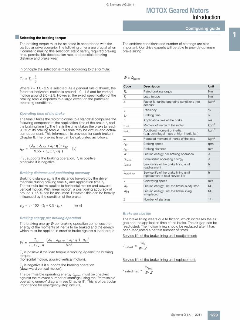
1 ■ Coolant temperature and site altitude
The rated power specified in the selection tables in section 8 applies to continuous duty (S1) or inverter-fed operation (S9) according to IEC 60034-1 at the corresponding rated frequency, a coolant temperature of 40 °C and a site altitude of 1.000 m above sea level. Please contact us if higher coolant tempera-tures are to be used. The table containing correction factors provides a rough idea of derating if conditions are different.
This results in a permissible motor power of:
If the permissible motor power is no longer adequate for the drive, a check should be performed as to whether or not the motor with the next higher rated power fulfills the requirements.
Factor kHT for different site altitudes and / or coolant temperatures
■ Selecting the brake
MOTOX geared motors can be supplied with fail-safe spring-operated disk brakes in order to reduce the motor's follow-on time or to hold loads, for example. Our MODULOG modular system can be used to assign / attach several brake sizes to one motor size. See Chapter 8 for information on assigning brake sizes to motor sizes, and on possible brake options.
The following information is required in order to select and check the brake:• Speed• Load torque• Moments of inertia• Number of startings
Code Description Unit
Pperm Permissible motor power kW
Prated Rated motor power kW
kHT Factor for abnormal coolant temperature and site altitude
–
Pperm = Prated · kHT
Site altitude (SA)
Coolant temperature (CT)
m < 30 °C 30… 40 °C 45 °C 50 °C 55 °C 60 °C
1 000 1.07 1.00 0.96 0.92 0.87 0.82
1 500 1.04 0.97 0.93 0.89 0.84 0.79
2 000 1.00 0.94 0.90 0.86 0.82 0.77
2 500 0.96 0.90 0.86 0.83 0.78 0.74
3 000 0.92 0.86 0.82 0.79 0.75 0.70
3 500 0.88 0.82 0.79 0.75 0.71 0.67
4 000 0.82 0.77 0.74 0.71 0.67 0.63
© Siemens AG 2011
MOTOX Geared MotorsIntroduction
Configuring guide
1/29Siemens D 87.1 · 2011
1■ Selecting the braking torque
The braking torque must be selected in accordance with the particular drive scenario. The following criteria are crucial when it comes to making this selection: static safety, required braking time, permissible deceleration rate, and possible braking distance and brake wear.
The ambient conditions and number of startings are also important. Our drive experts will be able to provide optimum brake sizing.
In principle the selection is made according to the formula:
Where k = 1.0 - 2.5 is selected. As a general rule of thumb, the factor for horizontal motion is around 1.0 - 1.5 and for vertical motion around 2.0 - 2.5. However, the exact specification of the braking torque depends to a large extent on the particular operating conditions.
Operating time of the brake
The time it takes the motor to come to a standstill comprises the following components: the application time of the brake t1 and the braking time tbr. The first is the time it takes the brake to reach 90 % of its braking torque. This time may be circuit- and actua-tion-dependent. This information is provided for each brake in Chapter 8. The braking time can be calculated as follows:
If Tx supports the braking operation, Tx is positive, otherwise it is negative.
Braking distance and positioning accuracy
Braking distance sbr is the distance traveled by the driven machine during braking time tbr and application time t1. The formula below applies to horizontal motion and upward vertical motion. With linear motion, a positioning accuracy of around ± 15 % can be assumed. However, this can be heavily influenced by the condition of the brake.
Braking energy per braking operation
The braking energy W per braking operation comprises the energy of the moments of inertia to be braked and the energy which must be applied in order to brake against a load torque:
Tx is positive if the load torque is working against the braking torque (horizontal motion, upward vertical motion).
Tx is negative if it supports the braking operation (downward vertical motion).
The permissible operating energy Qperm must be checked against the relevant number of startings using the "Permissible operating energy" diagram (see Chapter 8). This is of particular importance for emergency-stop circuits.
Brake service life
The brake lining wears due to friction, which increases the air gap and the application time of the brake. The air gap can be readjusted. The friction lining should be replaced after it has been readjusted a certain number of times.
Service life of the brake lining until readjustment:
Service life of the brake lining until replacement:
Tbr Txkη---⋅>
[s]tbr
JM Jadd Jx η⋅+ +( ) nbr⋅9 55 Tbr Tx± η⋅( )⋅
---------------------------------------------------------------=.
sbr = v · 100 · (t1 + 0.5 · tbr) [mm]
WTbr
Tbr Tx η⋅±--------------------------
JM Jperm Jx η⋅+ +( ) nbr2⋅
182 5--------------------------------------------------------------------------⋅=
.
Code Description Unit
Tbr Rated braking torque Nm
Tx Load torque Nm
k Factor for taking operating conditions into account
kgm²
η Efficiency %
tbr Braking time s
t1 Application time of the brake ms
Jmot Moment of inertia of the motor kgm2
Jadd Additional moment of inertia (e.g. centrifugal mass or high inertia fan)
kgm2
Jx Reduced moment of inertia of the load kgm²
nbr Braking speed rpm
sbr Braking distance mm
W Friction energy per braking operation J
Qperm Permissible operating energy J
Lrated Service life of the brake lining until readjustment
h
Lratedmax Service life of the brake lining until replacement = total service life
h
v Conveying speed m/s
WV Friction energy until the brake is adjusted MJ
Wtot Friction energy until the brake lining is replaced
MJ
Z Number of startings 1/h
W < Qperm
LratedWV
W Z⋅-------------=
LratedmaxWtot
W Z⋅-------------=
© Siemens AG 2011
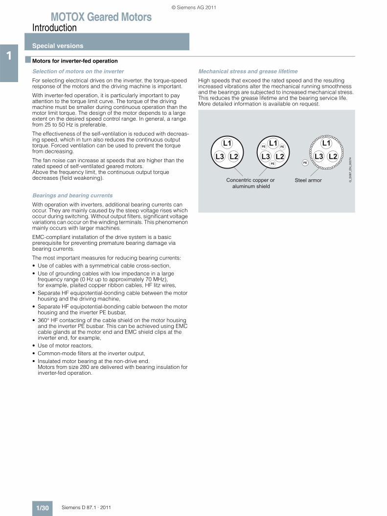
MOTOX Geared MotorsIntroduction
Special versions
1/30 Siemens D 87.1 · 2011
1 ■ Motors for inverter-fed operation
Selection of motors on the inverter
For selecting electrical drives on the inverter, the torque-speed response of the motors and the driving machine is important.
With inverter-fed operation, it is particularly important to pay attention to the torque limit curve. The torque of the driving machine must be smaller during continuous operation than the motor limit torque. The design of the motor depends to a large extent on the desired speed control range. In general, a range from 25 to 50 Hz is preferable.
The effectiveness of the self-ventilation is reduced with decreas-ing speed, which in turn also reduces the continuous output torque. Forced ventilation can be used to prevent the torque from decreasing.
The fan noise can increase at speeds that are higher than the rated speed of self-ventilated geared motors. Above the frequency limit, the continuous output torque decreases (field weakening).
Bearings and bearing currents
With operation with inverters, additional bearing currents can occur. They are mainly caused by the steep voltage rises which occur during switching. Without output filters, significant voltage variations can occur on the winding terminals. This phenomenon mainly occurs with larger machines.
EMC-compliant installation of the drive system is a basic prerequisite for preventing premature bearing damage via bearing currents.
The most important measures for reducing bearing currents:• Use of cables with a symmetrical cable cross-section,• Use of grounding cables with low impedance in a large
frequency range (0 Hz up to approximately 70 MHz), for example, plaited copper ribbon cables, HF litz wires,
• Separate HF equipotential-bonding cable between the motor housing and the driving machine,
• Separate HF equipotential-bonding cable between the motor housing and the inverter PE busbar,
• 360° HF contacting of the cable shield on the motor housing and the inverter PE busbar. This can be achieved using EMC cable glands at the motor end and EMC shield clips at the inverter end, for example,
• Use of motor reactors,• Common-mode filters at the inverter output,• Insulated motor bearing at the non-drive end.
Motors from size 280 are delivered with bearing insulation for inverter-fed operation.
Mechanical stress and grease lifetime
High speeds that exceed the rated speed and the resulting increased vibrations alter the mechanical running smoothness and the bearings are subjected to increased mechanical stress. This reduces the grease lifetime and the bearing service life. More detailed information is available on request.
L1
L2L3
L1
L2L3
L1
L2L3PE PE
PE PE
Concentric copper or aluminum shield
Steel armor G_D
087_
EN
_000
74
© Siemens AG 2011
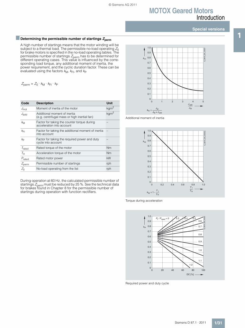
MOTOX Geared MotorsIntroduction
Special versions
1/31Siemens D 87.1 · 2011
1■ Determining the permissible number of startings Zperm
A high number of startings means that the motor winding will be subject to a thermal load. The permissible no-load operating Z0 for brake motors is specified in the no-load operating tables. The permissible number of startings Zperm has to be determined for different operating cases. This value is influenced by the corre-sponding load torque, any additional moment of inertia, the power requirement, and the cyclic duration factor. These can be evaluated using the factors kM, kFI, and kP.
During operation at 60 Hz, the calculated permissible number of startings Zperm must be reduced by 25 %. See the technical data for brakes found in Chapter 8 for the permissible number of startings during operation with function rectifiers.
Additional moment of inertia
Torque during acceleration
Required power and duty cycle
Code Description Unit
Jmot Moment of inertia of the motor kgm2
Jadd Additional moment of inertia (e.g. centrifugal mass or high inertial fan)
kgm2
kM Factor for taking the counter torque during acceleration into account
–
kFI Factor for taking the additional moment of inertiainto account
–
kP Factor for taking the required power and duty cycle into account
–
Trated Rated torque of the motor Nm
TH Acceleration torque of the motor Nm
Prated Rated motor power kW
Zperm Permissible number of startings rph
Z0 No-load operating from the list rph
Zperm = Z0 · kM · kFI · kP
0
k FI
0 1 2 3 4 5
G_M
015_
EN
_000
41
M
J
Jadd
kFl =MJ addJ
MJ
0.2
0.4
0.6
0.8
1.0
0.1
0.3
0.5
0.7
0.9
0
k M
0TTH
T H
1
1 -kM = 1T
0.2
0.4
0.6
0.8
1.0
0.1
0.3
0.5
0.7
0.9
0.2 0.4 0.6 0.8 1.0
G_M
015_
EN
_000
40a
0
kP
DC [%]
0 20 40 60 80 100
P / P = 0
G_M
015_
EN
_000
42
1 rated
0.2
0.4
0.6
0.8
1.0
0.1
0.3
0.5
0.7
0.90.2 0.4 0.5
0.6
0.7
1.0
1.1
1.2
0.9
0.8
© Siemens AG 2011
MOTOX Geared MotorsIntroduction
Special versions
1/32 Siemens D 87.1 · 2011
1 ■ Checking the input torque for mounted units
Geared motors are usually integrated, i.e. they are mounted on the gearbox directly and the products are supplied as complete drives. Alternatively, the gearboxes can also be supplied with various input units for motor mounting. The criteria below must be taken into account, particularly for special motors.
Maximum input speed
We recommend that four-pole motors are mounted in order to achieve optimum gearbox service life. Higher input speeds can have an effect on bearing service life and the thermal properties of the gearbox, among other things. See the section titled "Maximum speed", page 1/22.
Permissible radial force of the input shaft
Input units A and P can be powered by a V belt drive, for example. This results in a radial load on the input shaft. The permissible radial forces are specified in the section titled "Input unit".
Maximum input torque
The input units are primarily designed for four-pole standard three-phase AC motors. Considerably higher motor torques, which are above the maximum permissible input torque, may occur with special motors.
First of all, the continuous torque T1mot of the motor and the permissible input torque of the input unit T1 must be checked, along with the maximum torques (starting, breakdown, and braking). The torques for input units are specified in the section titled "Input unit". Please contact us if you have any questions.
Code Description Unit
T1 Permissible input torque of the input unit Nm
Trated Rated torque of the motor Nm
T1max Temporarily permissible max. input torque of the input unit
Nm
n1 Input speed of the motor rpm
P1 Input power of the motor kW
T1mot T1<P1 9550⋅
n1-----------------------=
T1max < 2.5 · T1
© Siemens AG 2011
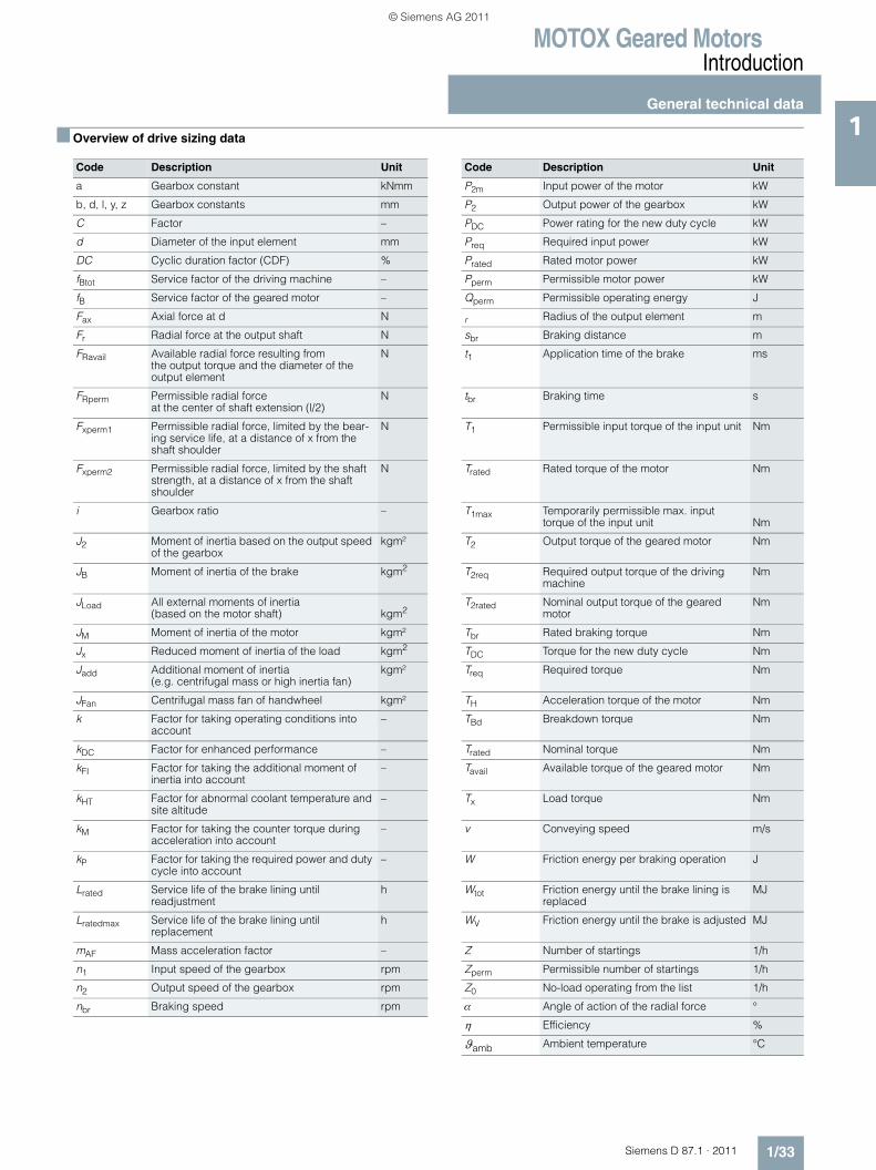
MOTOX Geared MotorsIntroduction
General technical data
1/33Siemens D 87.1 · 2011
1■ Overview of drive sizing data
Code Description Unit Code Description Unit
a Gearbox constant kNmm P2m Input power of the motor kW
b, d, l, y, z Gearbox constants mm P2 Output power of the gearbox kW
C Factor – PDC Power rating for the new duty cycle kW
d Diameter of the input element mm Preq Required input power kW
DC Cyclic duration factor (CDF) % Prated Rated motor power kW
fBtot Service factor of the driving machine – Pperm Permissible motor power kW
fB Service factor of the geared motor – Qperm Permissible operating energy J
Fax Axial force at d N r Radius of the output element m
Fr Radial force at the output shaft N sbr Braking distance m
FRavail Available radial force resulting from the output torque and the diameter of the output element
N t1 Application time of the brake ms
FRperm Permissible radial force at the center of shaft extension (l/2)
N tbr Braking time s
Fxperm1 Permissible radial force, limited by the bear-ing service life, at a distance of x from the shaft shoulder
N T1 Permissible input torque of the input unit Nm
Fxperm2 Permissible radial force, limited by the shaft strength, at a distance of x from the shaft shoulder
N Trated Rated torque of the motor Nm
i Gearbox ratio – T1max Temporarily permissible max. input torque of the input unit Nm
J2 Moment of inertia based on the output speed of the gearbox
kgm² T2 Output torque of the geared motor Nm
JB Moment of inertia of the brake kgm2 T2req Required output torque of the driving machine
Nm
JLoad All external moments of inertia (based on the motor shaft) kgm2
T2rated Nominal output torque of the geared motor
Nm
JM Moment of inertia of the motor kgm² Tbr Rated braking torque Nm
Jx Reduced moment of inertia of the load kgm2 TDC Torque for the new duty cycle Nm
Jadd Additional moment of inertia (e.g. centrifugal mass or high inertia fan)
kgm² Treq Required torque Nm
JFan Centrifugal mass fan of handwheel kgm² TH Acceleration torque of the motor Nm
k Factor for taking operating conditions into account
– TBd Breakdown torque Nm
kDC Factor for enhanced performance – Trated Nominal torque Nm
kFI Factor for taking the additional moment of inertia into account
– Tavail Available torque of the geared motor Nm
kHT Factor for abnormal coolant temperature and site altitude
– Tx Load torque Nm
kM Factor for taking the counter torque during acceleration into account
– v Conveying speed m/s
kP Factor for taking the required power and duty cycle into account
– W Friction energy per braking operation J
Lrated Service life of the brake lining until readjustment
h Wtot Friction energy until the brake lining is replaced
MJ
Lratedmax Service life of the brake lining until replacement
h WV Friction energy until the brake is adjusted MJ
mAF Mass acceleration factor – Z Number of startings 1/h
n1 Input speed of the gearbox rpm Zperm Permissible number of startings 1/h
n2 Output speed of the gearbox rpm Z0 No-load operating from the list 1/h
nbr Braking speed rpm α Angle of action of the radial force °
η Efficiency %
ϑamb Ambient temperature °C
© Siemens AG 2011
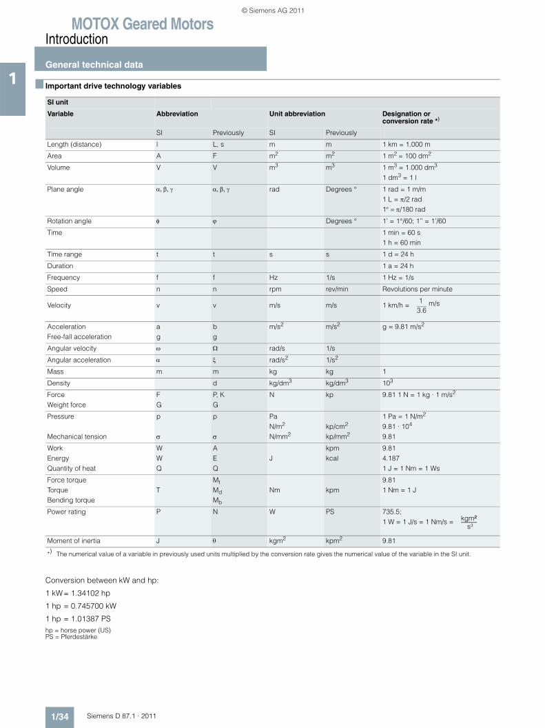
MOTOX Geared MotorsIntroduction
General technical data
1/34 Siemens D 87.1 · 2011
1 ■ Important drive technology variables
Conversion between kW and hp:
1 kW= 1.34102 hp
1 hp = 0.745700 kW
1 hp = 1.01387 PShp = horse power (US)PS = Pferdestärke
SI unit
Variable Abbreviation Unit abbreviation Designation or conversion rate *)
SI Previously SI Previously
Length (distance) l L, s m m 1 km = 1.000 m
Area A F m2 m2 1 m2 = 100 dm2
Volume V V m3 m3 1 m3 = 1.000 dm3 1 dm3 = 1 l
Plane angle α, β, γ α, β, γ rad Degrees ° 1 rad = 1 m/m1 L = π/2 rad 1° = π/180 rad
Rotation angle φ ϕ Degrees ° 1’ = 1°/60; 1’’ = 1’/60
Time 1 min = 60 s 1 h = 60 min
Time range t t s s 1 d = 24 h
Duration 1 a = 24 h
Frequency f f Hz 1/s 1 Hz = 1/s
Speed n n rpm rev/min Revolutions per minute
Velocity v v m/s m/s 1 km/h =
AccelerationFree-fall acceleration
ag
bg
m/s2 m/s2 g = 9.81 m/s2
Angular velocity ω Ω rad/s 1/s
Angular acceleration α ξ rad/s2 1/s2
Mass m m kg kg 1
Density d kg/dm3 kg/dm3 103
ForceWeight force
FG
P, KG
N kp 9.81 1 N = 1 kg · 1 m/s2
Pressure
Mechanical tension
p
σ
p
σ
PaN/m2
N/mm2kp/cm2
kp/mm2
1 Pa = 1 N/m2
9.81 · 104
9.81
WorkEnergyQuantity of heat
WWQ
AEQ
Jkpmkcal
9.814.1871 J = 1 Nm = 1 Ws
Force torqueTorqueBending torque
TMt
Md
Mb
Nm kpm9.811 Nm = 1 J
Power rating P N W PS 735.5; 1 W = 1 J/s = 1 Nm/s =
Moment of inertia J θ kgm2 kpm2 9.81
*) The numerical value of a variable in previously used units multiplied by the conversion rate gives the numerical value of the variable in the SI unit.
13.6
m/s
kgm²s³
© Siemens AG 2011
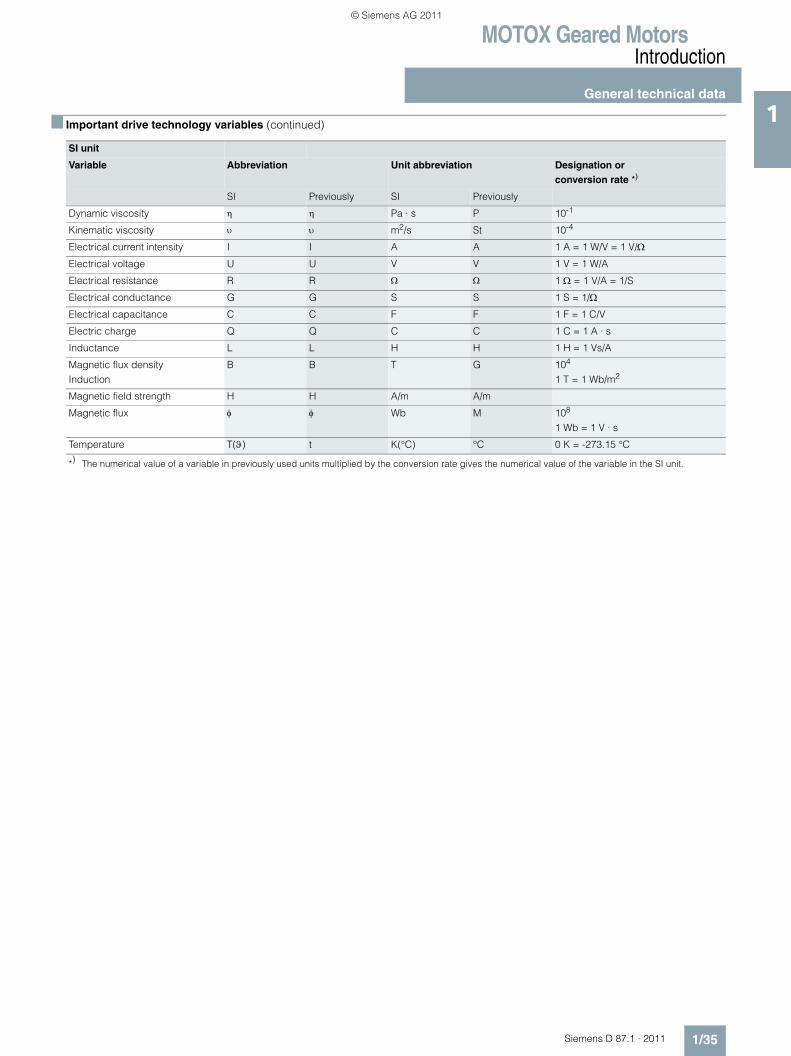
MOTOX Geared MotorsIntroduction
General technical data
1/35Siemens D 87.1 · 2011
1■ Important drive technology variables (continued)
SI unit
Variable Abbreviation Unit abbreviation Designation orconversion rate *)
SI Previously SI Previously
Dynamic viscosity η η Pa · s P 10-1
Kinematic viscosity υ υ m2/s St 10-4
Electrical current intensity I I A A 1 A = 1 W/V = 1 V/Ω
Electrical voltage U U V V 1 V = 1 W/A
Electrical resistance R R Ω Ω 1 Ω = 1 V/A = 1/S
Electrical conductance G G S S 1 S = 1/Ω
Electrical capacitance C C F F 1 F = 1 C/V
Electric charge Q Q C C 1 C = 1 A · s
Inductance L L H H 1 H = 1 Vs/A
Magnetic flux densityInduction
B B T G 104 1 T = 1 Wb/m2
Magnetic field strength H H A/m A/m
Magnetic flux φ φ Wb M 108
1 Wb = 1 V · s
Temperature T(ϑ) t K(°C) °C 0 K = -273.15 °C
*) The numerical value of a variable in previously used units multiplied by the conversion rate gives the numerical value of the variable in the SI unit.
© Siemens AG 2011
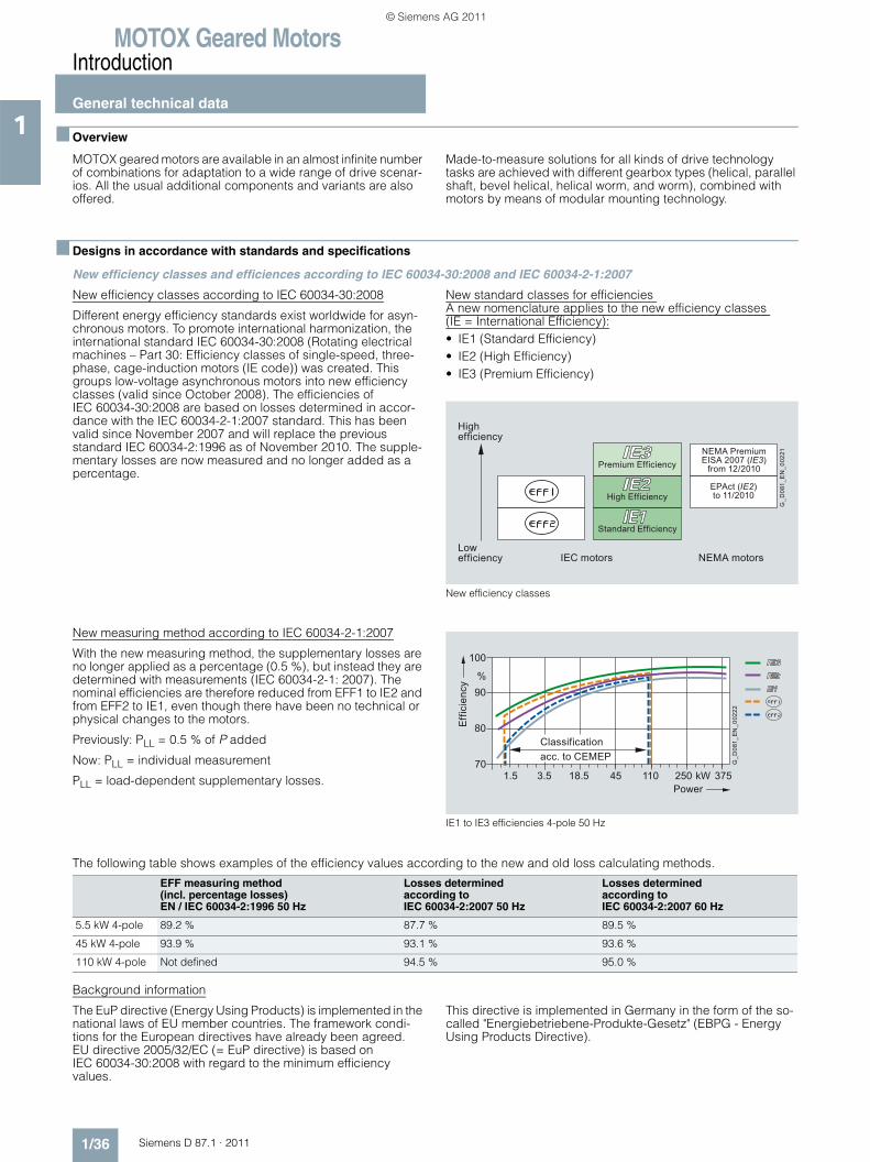
MOTOX Geared MotorsIntroduction
General technical data
1/36 Siemens D 87.1 · 2011
1 ■ Overview
MOTOX geared motors are available in an almost infinite number of combinations for adaptation to a wide range of drive scenar-ios. All the usual additional components and variants are also offered.
Made-to-measure solutions for all kinds of drive technology tasks are achieved with different gearbox types (helical, parallel shaft, bevel helical, helical worm, and worm), combined with motors by means of modular mounting technology.
■ Designs in accordance with standards and specifications
New efficiency classes and efficiences according to IEC 60034-30:2008 and IEC 60034-2-1:2007
New efficiency classes according to IEC 60034-30:2008
Different energy efficiency standards exist worldwide for asyn-chronous motors. To promote international harmonization, the international standard IEC 60034-30:2008 (Rotating electrical machines – Part 30: Efficiency classes of single-speed, three-phase, cage-induction motors (IE code)) was created. This groups low-voltage asynchronous motors into new efficiency classes (valid since October 2008). The efficiencies of IEC 60034-30:2008 are based on losses determined in accor-dance with the IEC 60034-2-1:2007 standard. This has been valid since November 2007 and will replace the previous standard IEC 60034-2:1996 as of November 2010. The supple-mentary losses are now measured and no longer added as a percentage.
New standard classes for efficiencies A new nomenclature applies to the new efficiency classes (IE = International Efficiency):• IE1 (Standard Efficiency)• IE2 (High Efficiency)• IE3 (Premium Efficiency)
New efficiency classes
New measuring method according to IEC 60034-2-1:2007
With the new measuring method, the supplementary losses are no longer applied as a percentage (0.5 %), but instead they are determined with measurements (IEC 60034-2-1: 2007). The nominal efficiencies are therefore reduced from EFF1 to IE2 and from EFF2 to IE1, even though there have been no technical or physical changes to the motors.
Previously: PLL = 0.5 % of P added
Now: PLL = individual measurement
PLL = load-dependent supplementary losses.
IE1 to IE3 efficiencies 4-pole 50 Hz
The following table shows examples of the efficiency values according to the new and old loss calculating methods.
Background information
The EuP directive (Energy Using Products) is implemented in the national laws of EU member countries. The framework condi-tions for the European directives have already been agreed. EU directive 2005/32/EC (= EuP directive) is based on IEC 60034-30:2008 with regard to the minimum efficiency values.
This directive is implemented in Germany in the form of the so-called "Energiebetriebene-Produkte-Gesetz" (EBPG - Energy Using Products Directive).
NEMA motorsIEC motorsLowefficiency
High efficiency
EPAct (IE2)to 11/2010
NEMA PremiumEISA 2007 (IE3)
from 12/2010
G_D
081_
EN
_002
21
Standard Efficiency
High Efficiency
Premium Efficiency
G_D
081_
EN
_002
22Classificationacc. to CEMEP
Power
Effic
ienc
y
1.5 3.5 18.5 45 110 250 375
100
90
80
70
%
kW
EFF measuring method (incl. percentage losses)EN / IEC 60034-2:1996 50 Hz
Losses determinedaccording toIEC 60034-2:2007 50 Hz
Losses determinedaccording toIEC 60034-2:2007 60 Hz
5.5 kW 4-pole 89.2 % 87.7 % 89.5 %
45 kW 4-pole 93.9 % 93.1 % 93.6 %
110 kW 4-pole Not defined 94.5 % 95.0 %
© Siemens AG 2011
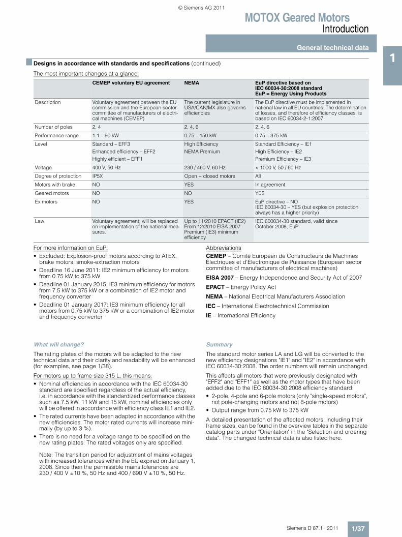
MOTOX Geared MotorsIntroduction
General technical data
1/37Siemens D 87.1 · 2011
1■ Designs in accordance with standards and specifications (continued)
The most important changes at a glance:
For more information on EuP:• Excluded: Explosion-proof motors according to ATEX,
brake motors, smoke-extraction motors• Deadline 16 June 2011: IE2 minimum efficiency for motors
from 0.75 kW to 375 kW• Deadline 01 January 2015: IE3 minimum efficiency for motors
from 7.5 kW to 375 kW or a combination of IE2 motor and frequency converter
• Deadline 01 January 2017: IE3 minimum efficiency for all motors from 0.75 kW to 375 kW or a combination of IE2 motor and frequency converter
AbbreviationsCEMEP – Comité Européen de Constructeurs de Machines Électriques et d'Électronique de Puissance (European sector committee of manufacturers of electrical machines)
EISA 2007 – Energy Independence and Security Act of 2007
EPACT – Energy Policy Act
NEMA – National Electrical Manufacturers Association
IEC – International Electrotechnical Commission
IE – International Efficiency
What will change?
The rating plates of the motors will be adapted to the new technical data and their clarity and readability will be enhanced (for examples, see page 1/38).
For motors up to frame size 315 L, this means:• Nominal efficiencies in accordance with the IEC 60034-30
standard are specified regardless of the actual efficiency, i.e. in accordance with the standardized performance classes such as 7.5 kW, 11 kW and 15 kW, nominal efficiencies only will be offered in accordance with efficiency class IE1 and IE2.
• The rated currents have been adapted in accordance with the new efficiencies. The motor rated currents will increase mini-mally (by up to 3 %).
• There is no need for a voltage range to be specified on the new rating plates. The rated voltages only are specified.
Note: The transition period for adjustment of mains voltages with increased tolerances within the EU expired on January 1, 2008. Since then the permissible mains tolerances are 230 / 400 V ±10 %, 50 Hz and 400 / 690 V ±10 %, 50 Hz.
Summary
The standard motor series LA and LG will be converted to the new efficiency designations "IE1" and "IE2" in accordance with IEC 60034-30:2008. The order numbers will remain unchanged.
This affects all motors that were previously designated with "EFF2" and "EFF1" as well as the motor types that have been added due to the IEC 60034-30:2008 efficiency standard: • 2-pole, 4-pole and 6-pole motors (only "single-speed motors",
not pole-changing motors and not 8-pole motors) • Output range from 0.75 kW to 375 kW
A detailed presentation of the affected motors, including their frame sizes, can be found in the overview tables in the separate catalog parts under "Orientation" in the "Selection and ordering data". The changed technical data is also listed here.
CEMEP voluntary EU agreement NEMA EuP directive based on IEC 60034-30:2008 standardEuP = Energy Using Products
Description Voluntary agreement between the EU commission and the European sector committee of manufacturers of electri-cal machines (CEMEP)
The current legislature in USA/CAN/MX also governs efficiencies
The EuP directive must be implemented in national law in all EU countries. The determination of losses, and therefore of efficiency classes, is based on IEC 60034-2-1:2007
Number of poles 2, 4 2, 4, 6 2, 4, 6
Performance range 1.1 – 90 kW 0.75 – 150 kW 0.75 – 375 kW
Level Standard – EFF3 Enhanced efficiency – EFF2Highly efficient – EFF1
High EfficiencyNEMA Premium
Standard Efficiency – IE1 High Efficiency – IE2Premium Efficiency – IE3
Voltage 400 V, 50 Hz 230 / 460 V, 60 Hz < 1000 V, 50 / 60 Hz
Degree of protection IP5X Open + closed motors All
Motors with brake NO YES In agreement
Geared motors NO NO YES
Ex motors NO YES EuP directive – NOIEC 60034-30 – YES (but explosion protection always has a higher priority)
Law Voluntary agreement; will be replaced on implementation of the national mea-sures.
Up to 11/2010 EPACT (IE2)From 12/2010 EISA 2007Premium (IE3) minimum efficiency
IEC 600034-30 standard, valid since October 2008, EuP
© Siemens AG 2011
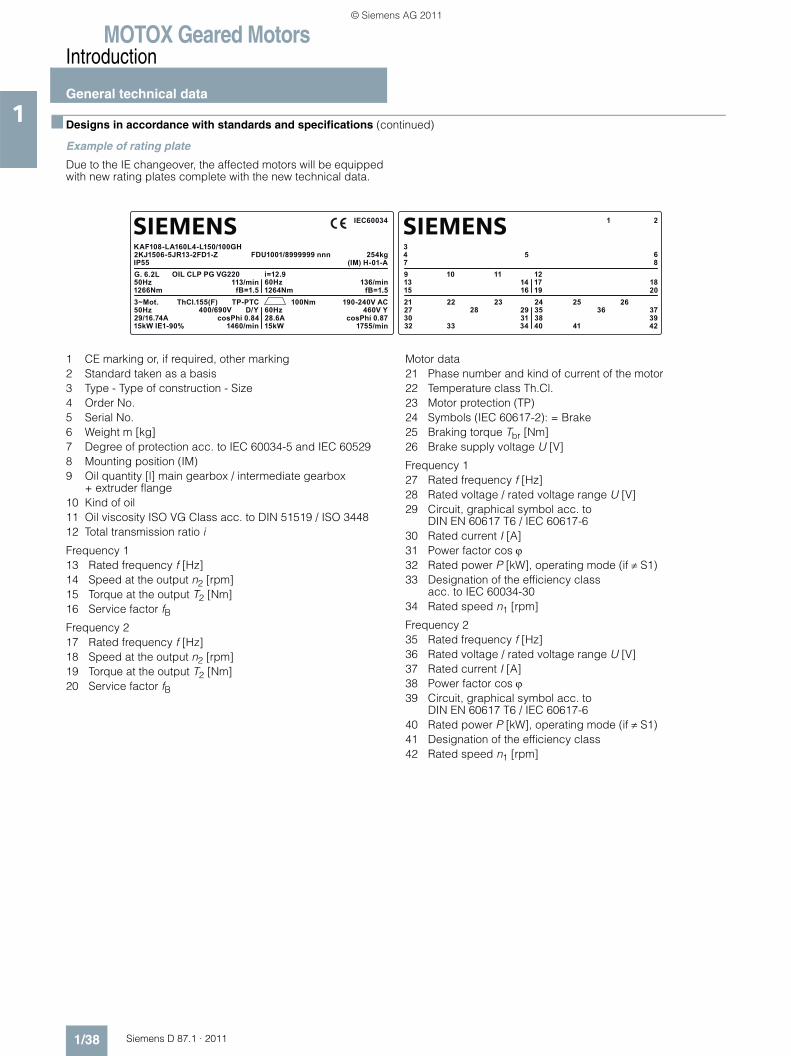
MOTOX Geared MotorsIntroduction
General technical data
1/38 Siemens D 87.1 · 2011
1 ■ Designs in accordance with standards and specifications (continued)
Example of rating plate
Due to the IE changeover, the affected motors will be equipped with new rating plates complete with the new technical data.
1 CE marking or, if required, other marking2 Standard taken as a basis3 Type - Type of construction - Size4 Order No.5 Serial No.6 Weight m [kg]7 Degree of protection acc. to IEC 60034-5 and IEC 605298 Mounting position (IM)9 Oil quantity [l] main gearbox / intermediate gearbox
+ extruder flange10 Kind of oil11 Oil viscosity ISO VG Class acc. to DIN 51519 / ISO 344812 Total transmission ratio i
Frequency 113 Rated frequency f [Hz]14 Speed at the output n2 [rpm]15 Torque at the output T2 [Nm]16 Service factor fBFrequency 217 Rated frequency f [Hz]18 Speed at the output n2 [rpm]19 Torque at the output T2 [Nm]20 Service factor fB
Motor data21 Phase number and kind of current of the motor22 Temperature class Th.Cl.23 Motor protection (TP)24 Symbols (IEC 60617-2): = Brake25 Braking torque Tbr [Nm]26 Brake supply voltage U [V]
Frequency 127 Rated frequency f [Hz]28 Rated voltage / rated voltage range U [V]29 Circuit, graphical symbol acc. to
DIN EN 60617 T6 / IEC 60617-630 Rated current I [A]31 Power factor cos ϕ32 Rated power P [kW], operating mode (if ≠ S1)33 Designation of the efficiency class
acc. to IEC 60034-3034 Rated speed n1 [rpm]
Frequency 235 Rated frequency f [Hz]36 Rated voltage / rated voltage range U [V]37 Rated current I [A]38 Power factor cos ϕ39 Circuit, graphical symbol acc. to
DIN EN 60617 T6 / IEC 60617-640 Rated power P [kW], operating mode (if ≠ S1)41 Designation of the efficiency class42 Rated speed n1 [rpm]
SIEMENSSIEMENS
13
273032
31 3835
25 2636 37
393433 40 41 42
28
1521 22 23 24
29
1416 19 20
3479 10 11 12
17 18
5 6
21
8
50Hz
50Hz29/16.74A15kW IE1-90%
cosPhi 0.84 28.6A60Hz
100Nm 190-240V AC460V Y
cosPhi 0.871460/min 15kW 1755/min
400/690V
1266Nm3~Mot. ThCl.155(F) TP-PTC
D/Y
113/minfB=1.5 1264Nm fB=1.5
KAF108-LA160L4-L150/100GH2KJ1506-5JR13-2FD1-ZIP55G. 6.2L OIL CLP PG VG220 i=12.9
60Hz 136/min
FDU1001/8999999 nnn 254kg
IEC60034
(IM) H-01-A
© Siemens AG 2011
MOTOX Geared MotorsIntroduction
General technical data
1/39Siemens D 87.1 · 2011
1■ Designs in accordance with standards and specifications (continued)
Minimum efficiencies required by law
In 1997, an act was passed in the USA to define minimum efficiencies for low-voltage three-phase AC motors (EPACT = Energy Policy Act). An act is in force in Canada that is largely identical, although it is based on different verification methods. The efficiency is verified for these motors for the USA using IEEE 112, Test Method B and for Canada using CSA-C390. Apart from a few exceptions, all low-voltage three-phase AC motors exported to the USA or Canada must comply with the legal efficiency requirements.
The law demands minimum efficiency levels for motors with a voltage of 230 and 460 V at 60 Hz, in the power range 1 to 200 hp (0.75 to 160 kW) with 2, 4, and 6 poles. Explosion-proof motors must also be included. The EPACT efficiency requirements exclude, for example: • Motors whose size power classification does not correspond
with the standard series according to NEMA MG1-12.• Flange-mounting motors without feet• Brake motors• Inverter-fed motors• Motors with design letter C and higher.
For more information on EPACT:
www.eren.doe.gov/
Special requirements for the USA: Energy Policy Act
The act lays down that the nominal efficiency at full load and a "CC" number (Compliance Certification) must be included on the rating plate. The "CC" number is issued by the US Department of Energy (DOE). The following information is stamped on the rating plate of EPACT motors which must be marked by law: Nominal efficiency (service factor SF 1.15), design letter, code letter, CONT, CC no. CC 032A (Siemens), and NEMA MG1-12.
Special requirements for Canada: CSA – Energy Efficiency Verification
These motors fulfill the minimum efficiency requirements laid down by the CSA standard C390. These motors can be ordered and feature the CSA-E mark on their rating plates.
NEMA – National Electrical Manufacturing Association
Data on the rating plate:
Rated voltage range, design letter, code letter, CONT, and NEMA MG1-12.
Order code:Design in accordance with NEMA N65
UL-R – Underwriters Laboratories Inc. listing
The motors are listed for up to 600 V by Underwriters Laborato-ries Inc. ("Recognition Mark" = R/C).
Motor voltages up to 600 V are certified in accordance with UL.
"UL Recognition Mark" is included on the rating plate of the motor.
In addition, the motor is designed to meet the NEMA MG1-12 electrical standard and includes the following data on the rating plate:
Rated voltage, nominal efficiency, design letter, code letter, CONT, and NEMA MG1-12.
Externally or internally mounted components such as:• Motor protection• Heating element• External fan unit• Brake• Encoder• Plug connection
are UL-R/C, CSA, or C-US listed or used by manufacturers in accordance with regulations.
UL-R/C cable glands must be used for cable entry.
Order code:Design in accordance with UL-R N37
© Siemens AG 2011
MOTOX Geared MotorsIntroduction
General technical data
1/40 Siemens D 87.1 · 2011
1 ■ Designs in accordance with standards and specifications (continued)
CSA – Canadian Standard Association
Motors are approved for up to 690 V in accordance with the Canadian regulations of the "Canadian Standard Association" (CSA). Externally or internally mounted components which are used are listed by CSA or are used by manufacturers in accor-dance with regulations. The CSA mark and the rated voltage are included on the rating plate.
When energy-saving motors are ordered, they also include the CSA-E mark on the rating plate.
Order code:Design in accordance with CSA N36
UL-R and CSA approval
UL-R approval and CSA approval can also be ordered together for the motors.
Order code:Design in accordance with UL-R and CSA N38
CCC – China Compulsory Certification
"Small power motors" which are exported to China must be certified up to a rated power of:
2-pole: ≤ 2.2 kW
4-pole: ≤ 1.1 kW
6-pole: ≤ 0.75 kW
8-pole: ≤ 0.55 kW
The LA motors which must be certified are certified by the CQC (China Quality Cert. Center). When one of these motors is ordered, the logo "CCC (Safety Mark)" is included on the rating plate and the packaging.
Notes:
Chinese customs checks the need for certification of imported products by means of the commodity code.
The following do not need to be certified:• Motors imported to China which have already been installed
in a machine• Repair parts
Order code:Design in accordance with CCC N67
CEEL – China Energy Efficiency Label
In June 2008 China introduced mandatory energy efficiency labeling for electric motors.
Since September 1, 2008, when the transition period expired, the applicable electrical motors could only be imported and sold in China with a valid "China Energy Efficiency Label".
The motor must be labeled with the "China Energy Efficiency Label" sticker, which states the efficiency class.
Apart from the Energy Label sticker (dimensions 80 x 54 mm) the efficiency must also be stated on the rating plate.
The labeling requirements apply to 2, 4 and 6-pole motors with a line frequency of 50 Hz and rated voltages of up to 690 V.
Efficiency classes 2 and 3 apply here to motors with a rated power of 0.55 kW to 315 kW and efficiency class 1 applies to motors with a rated power from 3 kW to 315 kW.
Order code:Design in accordance with China Energy Efficiency Label K69
GOST-R conformity
The following gearboxes can be supplied, certified according to GOST-R:• Helical gearboxes• Bevel helical gearboxes• Parallel shaft gearboxes• Helical worm gearboxes• Worm gearboxes• CAVEX worm gearboxes
Order code:Design in accordance with GOST N30
VIK version
For a VIK version, select an IEC motor from Catalog D 81.1 that can be mounted on gearboxes with an input unit K2 or K4.
®
© Siemens AG 2011
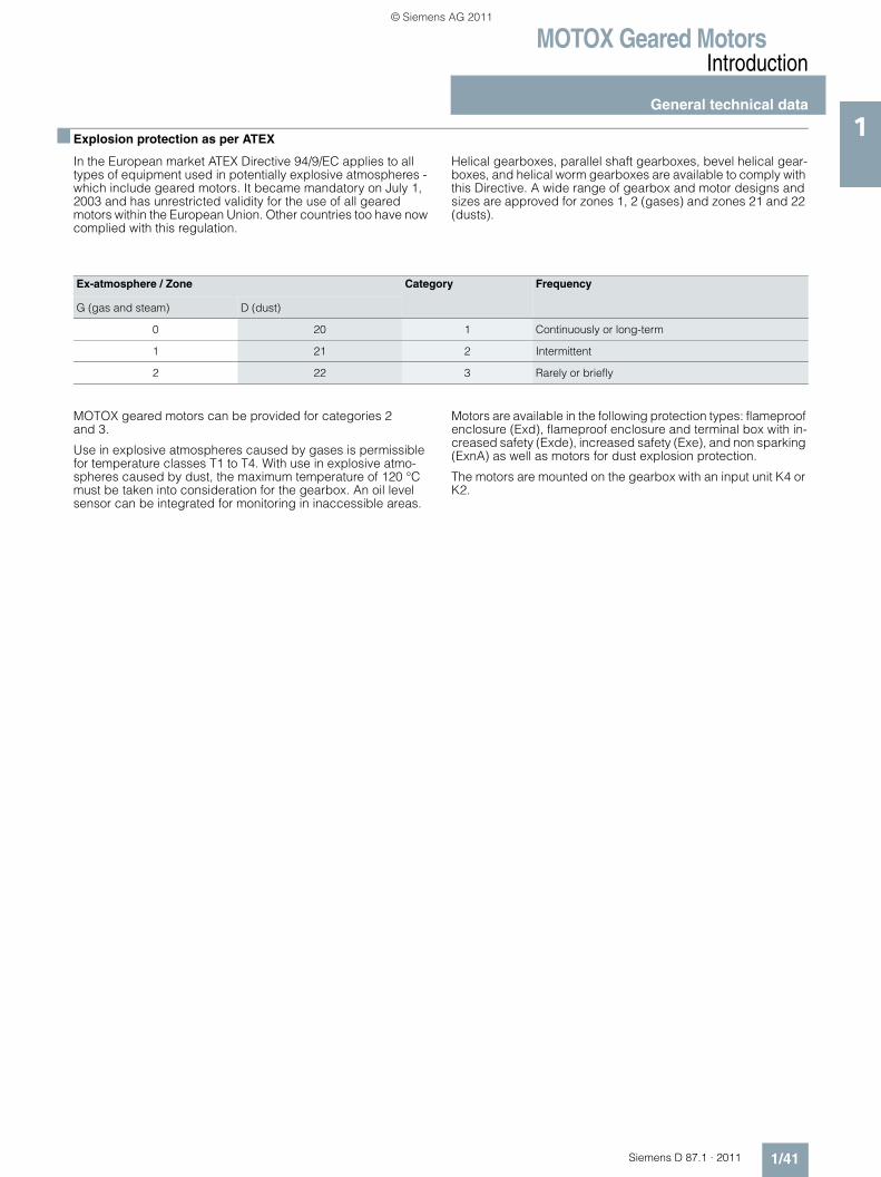
MOTOX Geared MotorsIntroduction
General technical data
1/41Siemens D 87.1 · 2011
1■ Explosion protection as per ATEX
In the European market ATEX Directive 94/9/EC applies to all types of equipment used in potentially explosive atmospheres - which include geared motors. It became mandatory on July 1, 2003 and has unrestricted validity for the use of all geared motors within the European Union. Other countries too have now complied with this regulation.
Helical gearboxes, parallel shaft gearboxes, bevel helical gear-boxes, and helical worm gearboxes are available to comply with this Directive. A wide range of gearbox and motor designs and sizes are approved for zones 1, 2 (gases) and zones 21 and 22 (dusts).
MOTOX geared motors can be provided for categories 2 and 3.
Use in explosive atmospheres caused by gases is permissible for temperature classes T1 to T4. With use in explosive atmo-spheres caused by dust, the maximum temperature of 120 °C must be taken into consideration for the gearbox. An oil level sensor can be integrated for monitoring in inaccessible areas.
Motors are available in the following protection types: flameproof enclosure (Exd), flameproof enclosure and terminal box with in-creased safety (Exde), increased safety (Exe), and non sparking (ExnA) as well as motors for dust explosion protection.
The motors are mounted on the gearbox with an input unit K4 or K2.
Ex-atmosphere / Zone Category Frequency
G (gas and steam) D (dust)
0 20 1 Continuously or long-term
1 21 2 Intermittent
2 22 3 Rarely or briefly
© Siemens AG 2011
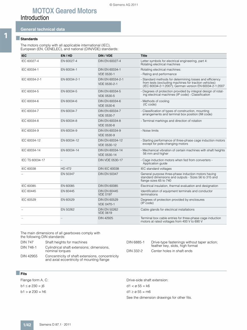
MOTOX Geared MotorsIntroduction
General technical data
1/42 Siemens D 87.1 · 2011
1 ■ Standards
The motors comply with all applicable international (IEC), European (EN, CENELEC), and national (DIN/VDE) standards:
The main dimensions of all gearboxes comply with the following DIN standards:
DIN 747 Shaft heights for machinesDIN 748-1 Cylindrical shaft extensions; dimensions,
nominal torquesDIN 42955 Concentricity of shaft extensions, concentricity
and axial eccentricity of mounting flange
DIN 6885-1 Drive-type fastenings without taper action; feather key, slots, high format
DIN 332-2 Center holes in shaft ends
■ Fits
Flange form A, C:
b1 ≤ ø 230 = j6
b1 > ø 230 = h6
Drive-side shaft extension:
d1 < ø 55 = k6
d1 ≥ ø 55 = m6
See the dimension drawings for other fits.
IEC EN / HD DIN / VDE Title
IEC 60027-4 EN 60027-4 DIN EN 60027-4 Letter symbols for electrical engineering, part 4: Rotating electrical machines
IEC 60034-1 EN 60034-1 DIN EN 60034-1VDE 0530-1
Rotating electrical machines:- Rating and performance
IEC 60034-2-1 EN 60034-2-1 DIN EN 60034-2-1VDE 0530-2-1
- Standard methods for determining losses and efficiency from tests (excluding machines for traction vehicles) (IEC 60034-2-1:2007); German version EN 60034-2-1:2007
IEC 60034-5 EN 60034-5 DIN EN 60034-5VDE 0530-5
- Degrees of protection provided by integral design of rotat-ing electrical machines (IP code) - Classification
IEC 60034-6 EN 60034-6 DIN EN 60034-6VDE 0530-6
- Methods of cooling (IC code)
IEC 60034-7 EN 60034-7 DIN EN 60034-7VDE 0530-7
- Classification of types of construction, mounting arrangements and terminal box position (IM code)
IEC 60034-8 EN 60034-8 DIN EN 60034-8VDE 0530-8
- Terminal markings and direction of rotation
IEC 60034-9 EN 60034-9 DIN EN 60034-9VDE 0530-9
- Noise limits
IEC 60034-12 EN 60034-12 DIN EN 60034-12VDE 0530-12
- Starting performance of three-phase cage induction motors except for pole-changing motors
IEC 60034-14 EN 60034-14 DIN EN 60034-14VDE 0530-14
- Mechanical vibration of certain machines with shaft heights 56 mm and higher
IEC TS 60034-17 – DIN VDE 0530-17 - Cage induction motors when fed from converters - Application guide
IEC 60038 HD 472 DIN IEC 60038 IEC standard voltages
– EN 50347 DIN EN 50347 General purpose three-phase induction motors having standard dimensions and outputs - Sizes 56 to 315 and flange sizes 65 to 740
IEC 60085 EN 60085 DIN EN 60085 Electrical insulation, thermal evaluation and designation
IEC 60445 EN 60445 DIN EN 60445VDE 0197
Identification of equipment terminals and conductor terminations
IEC 60529 EN 60529 DIN EN 60529VDE 0470-1
Degrees of protection provided by enclosures (IP code)
– EN 50262 DIN EN 50262VDE 0619
Cable glands for electrical installations
– – DIN 42925 Terminal box cable entries for three-phase cage induction motors at rated voltages from 400 V to 690 V
© Siemens AG 2011
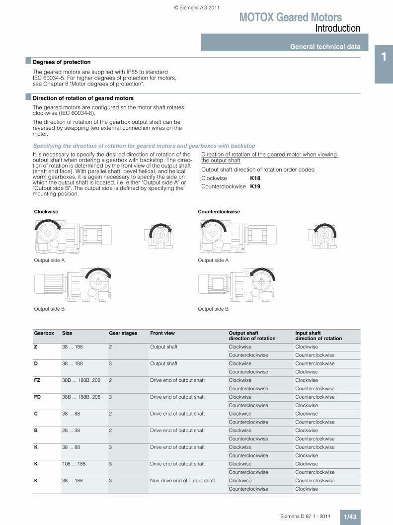
MOTOX Geared MotorsIntroduction
General technical data
1/43Siemens D 87.1 · 2011
1■ Degrees of protection
The geared motors are supplied with IP55 to standard IEC 60034-5. For higher degrees of protection for motors, see Chapter 8 "Motor degrees of protection".
■ Direction of rotation of geared motors
The geared motors are configured so the motor shaft rotates clockwise (IEC 60034-8).
The direction of rotation of the gearbox output shaft can be reversed by swapping two external connection wires on the motor.
Specifying the direction of rotation for geared motors and gearboxes with backstop
It is necessary to specify the desired direction of rotation of the output shaft when ordering a gearbox with backstop. The direc-tion of rotation is determined by the front view of the output shaft (shaft end face). With parallel shaft, bevel helical, and helical worm gearboxes, it is again necessary to specify the side on which the output shaft is located, i.e. either "Output side A" or "Output side B". The output side is defined by specifying the mounting position.
Direction of rotation of the geared motor when viewing the output shaft
Output shaft direction of rotation order codes:
Clockwise K18Counterclockwise K19
Clockwise Counterclockwise
Output side A Output side A
Output side B Output side B
Gearbox Size Gear stages Front view Output shaft direction of rotation
Input shaftdirection of rotation
Z 38 ... 188 2 Output shaft Clockwise Clockwise
Counterclockwise Counterclockwise
D 38 ... 188 3 Output shaft Clockwise Counterclockwise
Counterclockwise Clockwise
FZ 38B ... 188B, 208 2 Drive end of output shaft Clockwise Clockwise
Counterclockwise Counterclockwise
FD 38B ... 188B, 208 3 Drive end of output shaft Clockwise Counterclockwise
Counterclockwise Clockwise
C 38 ... 88 2 Drive end of output shaft Clockwise Clockwise
Counterclockwise Counterclockwise
B 28 ... 38 2 Drive end of output shaft Clockwise Clockwise
Counterclockwise Counterclockwise
K 38 ... 88 3 Drive end of output shaft Clockwise Counterclockwise
Counterclockwise Clockwise
K 108 ... 188 3 Drive end of output shaft Clockwise Clockwise
Counterclockwise Counterclockwise
K 38 ... 188 3 Non-drive end of output shaft Clockwise Counterclockwise
Counterclockwise Clockwise
© Siemens AG 2011
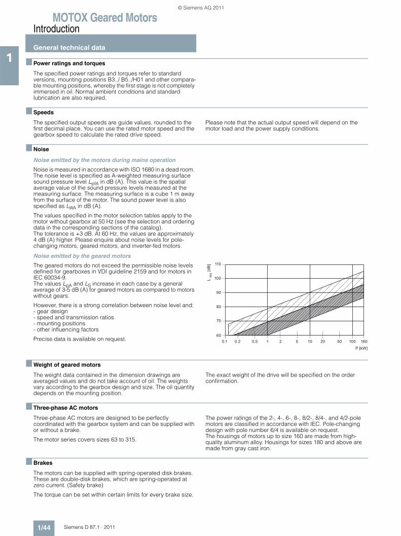
MOTOX Geared MotorsIntroduction
General technical data
1/44 Siemens D 87.1 · 2011
1 ■ Power ratings and torques
The specified power ratings and torques refer to standard versions, mounting positions B3../ B5../H01 and other compara-ble mounting positions, whereby the first stage is not completely immersed in oil. Normal ambient conditions and standard lubrication are also required.
■ Speeds
The specified output speeds are guide values, rounded to the first decimal place. You can use the rated motor speed and the gearbox speed to calculate the rated drive speed.
Please note that the actual output speed will depend on the motor load and the power supply conditions.
■ Noise
Noise emitted by the motors during mains operation
Noise is measured in accordance with ISO 1680 in a dead room. The noise level is specified as A-weighted measuring surface sound pressure level LpfA in dB (A). This value is the spatial average value of the sound pressure levels measured at the measuring surface. The measuring surface is a cube 1 m away from the surface of the motor. The sound power level is also specified as LWA in dB (A).
The values specified in the motor selection tables apply to the motor without gearbox at 50 Hz (see the selection and ordering data in the corresponding sections of the catalog). The tolerance is +3 dB. At 60 Hz, the values are approximately 4 dB (A) higher. Please enquire about noise levels for pole-changing motors, geared motors, and inverter-fed motors.
Noise emitted by the geared motors
The geared motors do not exceed the permissible noise levels defined for gearboxes in VDI guideline 2159 and for motors in IEC 60034-9. The values LpA and LS increase in each case by a general average of 3-5 dB (A) for geared motors as compared to motors without gears.
However, there is a strong correlation between noise level and:- gear design- speed and transmission ratios- mounting positions- other influencing factors
Precise data is available on request.
■ Weight of geared motors
The weight data contained in the dimension drawings are averaged values and do not take account of oil. The weights vary according to the gearbox design and size. The oil quantity depends on the mounting position.
The exact weight of the drive will be specified on the order confirmation.
■ Three-phase AC motors
Three-phase AC motors are designed to be perfectly coordinated with the gearbox system and can be supplied with or without a brake.
The motor series covers sizes 63 to 315.
The power ratings of the 2-, 4-, 6-, 8-, 8/2-, 8/4-, and 4/2-pole motors are classified in accordance with IEC. Pole-changing design with pole number 6/4 is available on request. The housings of motors up to size 160 are made from high-quality aluminum alloy. Housings for sizes 180 and above are made from gray cast iron.
■ Brakes
The motors can be supplied with spring-operated disk brakes. These are double-disk brakes, which are spring-operated at zero current. (Safety brake)
The torque can be set within certain limits for every brake size.
© Siemens AG 2011
MOTOX Geared MotorsIntroduction
General technical data
1/45Siemens D 87.1 · 2011
1■ Lubricants
All gearboxes are filled with lubricant at the factory. The lubri-cants used meet the requirements of DIN 51502. The gearboxes are filled with varying oil quantities (see operating instructions and rating plate) depending on their mounting position. If no specifications are made to the contrary, the standard lubricant is used.
Required quality of gear lubricants
The oils used in the MOTOX gearboxes are subject to stringent quality control. For MOTOX gearboxes, only CLP-quality oils are approved which contain ingredients to DIN 51517-3 for improve-ment of corrosion protection, resistance to ageing, and which re-duce wear in mixed-friction areas. The scuffing resistance in the FZG test to DIN 51354-2 must comply with stage 12 or higher under A/8.3/90 test conditions. In the FE-8 rolling bearing test to DIN 51817 rolling element wear must be under 30 mg and cage wear under 100 mg under D-7.5/80-80 test conditions.
In addition, the lubricants must meet the following quality requirements demanded by FLENDER:• Sufficiently high gray-staining resistance in accordance with
FVA 54 gray-staining test• Low degree of foaming with less than 15 % foam formation in
the FLENDER foam test• Suitable for the elastomer material used in the radial shaft
sealing of gearboxes• Compatible with residues of corrosion-protection agent and
run-in oils• Compatible with the paints used by Siemens in the gearbox
interiors• Compatible with liquid sealing between bolted-joint surfaces.
For a list of approved oils from different manufacturers please refer to the Operating Instructions BA 7300.
Furthermore, for use in worm gearboxes:
Low wear, high pitting resistance, and high efficiency (low temperature) in the cylindrical worm gearbox test.
For a list of approved oils from different manufacturers please refer to the Operating Instructions BA 7303.
© Siemens AG 2011
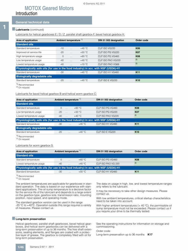
MOTOX Geared MotorsIntroduction
General technical data
1/46 Siemens D 87.1 · 2011
1 ■ Lubricants (continued)
Lubricants for helical gearboxes E / D / Z, parallel shaft gearbox F, bevel helical gearbox K:
Lubricants for bevel helical gearbox B and helical worm gearbox C:
Lubricants for worm gearbox S:
The ambient temperatures are applicable for gearboxes in stan-dard operation. The data is based on our experience with stan-dard applications. The oil sump temperature is a decisive factor for the service life of the lubricant and depends to a large extent on the gearbox type, gearbox size, transmission ratio, mounting position, input speed, and operating mode.
The standard gearbox version can be used in the range -20 °C to +40°C. Operation outside this range requires a variety of measures. Please contact us.
The data on usage in high, low, and lowest temperature ranges only refers to the lubricant.
It may be necessary to take other design measures. Please contact us.
With low ambient temperatures, critical startup characteristics need to be taken into account.
With higher ambient temperatures (> 40 °C), the permissible oil sump temperature must not be exceeded. Please contact us if you require your drive to be thermally tested.
■ Long-term preservation
Helical gearboxes, parallel shaft gearboxes, bevel helical gear-boxes, and helical worm gearboxes can be delivered with a long-term preservation of up to 36 months. The free shaft exten-sions, sealing elements, and flanges are coated with a protec-tive layer of grease. The gearbox is completely filled with oil for long-term preservation.
See the operating instructions for information on storage and commissioning.
Order code:Long-term preservation up to 36 months K17
Area of application Ambient temperature 1) DIN 51 502 designation Order code
Standard oilsStandard temperature -10 … +40 °C CLP ISO VG220 K06
Improved oil service life -20 … +50 °C CLP ISO PG VG220 K07
High temperature usage 0 … +60 °C CLP ISO PG VG460 K08
Low temperature usage -40 … +40 °C CLP ISO PAO VG220 2)
Lowest temperature usage -40 … +10 °C CLP ISO PAO VG68 2)
Physiologically safe oils (for use in the food industry) in acc. with NSF (USDA)-H1Standard temperature -30 … +40 °C CLP ISO H1 VG460 K11
Biologically degradable oilsStandard temperature -20 … +40 °C CLP ISO E VG220 K10
1) Recommended2) On request
Area of application Ambient temperature 1) DIN 51 502 designation Order code
Standard oils
Standard temperature 0 … +60 °C CLP ISO PG VG460 K08
Low temperature usage -20 … +50 °C CLP ISO PG VG220 K07
Lowest temperature usage -40 … +40 °C CLP ISO PAO VG220 2)
Physiologically safe oils (for use in the food industry) in acc. with NSF (USDA)-H1Standard temperature -30 … +40 °C CLP ISO H1 VG460 K11
Biologically degradable oilsStandard temperature -20 … +40 °C CLP ISO E VG220 K10
1) Recommended2) On request
Area of application Ambient temperature 1) DIN 51 502 designation Order code
Standard oils
Standard temperature 0 … +60 °C CLP ISO PG VG460 K08
Lowest temperature usage -40 … +40 °C CLP ISO PAO VG 220 2)
Physiologically safe oils (for use in the food industry) in acc. with NSF (USDA)-H1Standard temperature -30 … +50 °C CLP ISO H1 VG460 K11
1) Recommended2) On request
© Siemens AG 2011
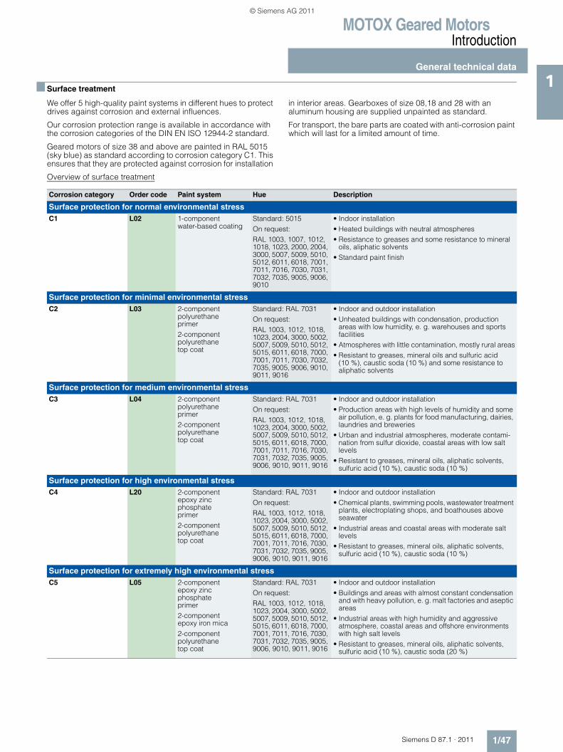
MOTOX Geared MotorsIntroduction
General technical data
1/47Siemens D 87.1 · 2011
1■ Surface treatment
We offer 5 high-quality paint systems in different hues to protect drives against corrosion and external influences.
Our corrosion protection range is available in accordance with the corrosion categories of the DIN EN ISO 12944-2 standard.
Geared motors of size 38 and above are painted in RAL 5015 (sky blue) as standard according to corrosion category C1. This ensures that they are protected against corrosion for installation
in interior areas. Gearboxes of size 08,18 and 28 with an aluminum housing are supplied unpainted as standard.
For transport, the bare parts are coated with anti-corrosion paint which will last for a limited amount of time.
Overview of surface treatment
Corrosion category Order code Paint system Hue Description
Surface protection for normal environmental stressC1 L02 1-component
water-based coatingStandard: 5015On request:RAL 1003, 1007, 1012, 1018, 1023, 2000, 2004, 3000, 5007, 5009, 5010, 5012, 6011, 6018, 7001, 7011, 7016, 7030, 7031, 7032, 7035, 9005, 9006, 9010
• Indoor installation• Heated buildings with neutral atmospheres• Resistance to greases and some resistance to mineral
oils, aliphatic solvents• Standard paint finish
Surface protection for minimal environmental stressC2 L03 2-component
polyurethane primer2-component polyurethane top coat
Standard: RAL 7031On request:RAL 1003, 1012, 1018, 1023, 2004, 3000, 5002, 5007, 5009, 5010, 5012, 5015, 6011, 6018, 7000, 7001, 7011, 7030, 7032, 7035, 9005, 9006, 9010, 9011, 9016
• Indoor and outdoor installation• Unheated buildings with condensation, production
areas with low humidity, e. g. warehouses and sports facilities
• Atmospheres with little contamination, mostly rural areas• Resistant to greases, mineral oils and sulfuric acid
(10 %), caustic soda (10 %) and some resistance to aliphatic solvents
Surface protection for medium environmental stressC3 L04 2-component
polyurethane primer2-component polyurethane top coat
Standard: RAL 7031On request:RAL 1003, 1012, 1018, 1023, 2004, 3000, 5002, 5007, 5009, 5010, 5012, 5015, 6011, 6018, 7000, 7001, 7011, 7016, 7030, 7031, 7032, 7035, 9005, 9006, 9010, 9011, 9016
• Indoor and outdoor installation• Production areas with high levels of humidity and some
air pollution, e. g. plants for food manufacturing, dairies, laundries and breweries
• Urban and industrial atmospheres, moderate contami-nation from sulfur dioxide, coastal areas with low salt levels
• Resistant to greases, mineral oils, aliphatic solvents, sulfuric acid (10 %), caustic soda (10 %)
Surface protection for high environmental stressC4 L20 2-component
epoxy zinc phosphateprimer2-component polyurethane top coat
Standard: RAL 7031On request:RAL 1003, 1012, 1018, 1023, 2004, 3000, 5002, 5007, 5009, 5010, 5012, 5015, 6011, 6018, 7000, 7001, 7011, 7016, 7030, 7031, 7032, 7035, 9005, 9006, 9010, 9011, 9016
• Indoor and outdoor installation• Chemical plants, swimming pools, wastewater treatment
plants, electroplating shops, and boathouses above seawater
• Industrial areas and coastal areas with moderate salt levels
• Resistant to greases, mineral oils, aliphatic solvents, sulfuric acid (10 %), caustic soda (10 %)
Surface protection for extremely high environmental stressC5 L05 2-component
epoxy zinc phosphate primer2-component epoxy iron mica2-component polyurethane top coat
Standard: RAL 7031On request:RAL 1003, 1012, 1018, 1023, 2004, 3000, 5002, 5007, 5009, 5010, 5012, 5015, 6011, 6018, 7000, 7001, 7011, 7016, 7030, 7031, 7032, 7035, 9005, 9006, 9010, 9011, 9016
• Indoor and outdoor installation• Buildings and areas with almost constant condensation
and with heavy pollution, e. g. malt factories and aseptic areas
• Industrial areas with high humidity and aggressive atmosphere, coastal areas and offshore environments with high salt levels
• Resistant to greases, mineral oils, aliphatic solvents, sulfuric acid (10 %), caustic soda (20 %)
© Siemens AG 2011
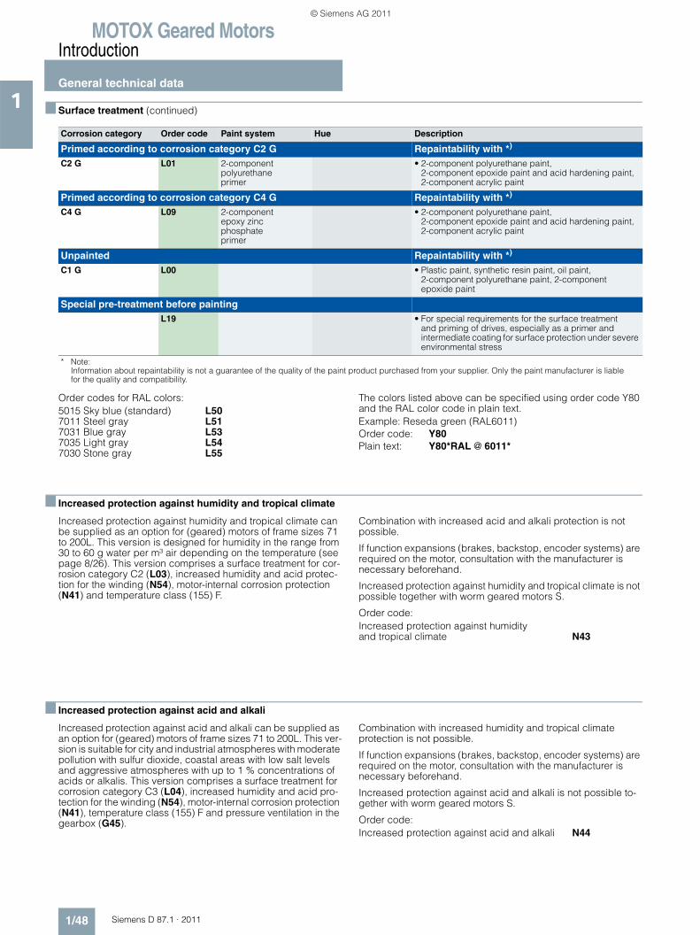
MOTOX Geared MotorsIntroduction
General technical data
1/48 Siemens D 87.1 · 2011
1 ■ Surface treatment (continued)
Order codes for RAL colors:5015 Sky blue (standard) L507011 Steel gray L517031 Blue gray L537035 Light gray L547030 Stone gray L55
The colors listed above can be specified using order code Y80 and the RAL color code in plain text.Example: Reseda green (RAL6011)Order code: Y80Plain text: Y80*RAL @ 6011*
■ Increased protection against humidity and tropical climate
Increased protection against humidity and tropical climate can be supplied as an option for (geared) motors of frame sizes 71 to 200L. This version is designed for humidity in the range from 30 to 60 g water per m³ air depending on the temperature (see page 8/26). This version comprises a surface treatment for cor-rosion category C2 (L03), increased humidity and acid protec-tion for the winding (N54), motor-internal corrosion protection (N41) and temperature class (155) F.
Combination with increased acid and alkali protection is not possible.
If function expansions (brakes, backstop, encoder systems) are required on the motor, consultation with the manufacturer is necessary beforehand.
Increased protection against humidity and tropical climate is not possible together with worm geared motors S.
Order code:Increased protection against humidityand tropical climate N43
■ Increased protection against acid and alkali
Increased protection against acid and alkali can be supplied as an option for (geared) motors of frame sizes 71 to 200L. This ver-sion is suitable for city and industrial atmospheres with moderate pollution with sulfur dioxide, coastal areas with low salt levels and aggressive atmospheres with up to 1 % concentrations of acids or alkalis. This version comprises a surface treatment for corrosion category C3 (L04), increased humidity and acid pro-tection for the winding (N54), motor-internal corrosion protection (N41), temperature class (155) F and pressure ventilation in the gearbox (G45).
Combination with increased humidity and tropical climate protection is not possible.
If function expansions (brakes, backstop, encoder systems) are required on the motor, consultation with the manufacturer is necessary beforehand.
Increased protection against acid and alkali is not possible to-gether with worm geared motors S.
Order code:Increased protection against acid and alkali N44
Corrosion category Order code Paint system Hue Description
Primed according to corrosion category C2 G Repaintability with *)
C2 G L01 2-component polyurethane primer
• 2-component polyurethane paint, 2-component epoxide paint and acid hardening paint, 2-component acrylic paint
Primed according to corrosion category C4 G Repaintability with *)
C4 G L09 2-component epoxy zinc phosphateprimer
• 2-component polyurethane paint, 2-component epoxide paint and acid hardening paint, 2-component acrylic paint
Unpainted Repaintability with *)
C1 G L00 • Plastic paint, synthetic resin paint, oil paint, 2-component polyurethane paint, 2-component epoxide paint
Special pre-treatment before paintingL19 • For special requirements for the surface treatment
and priming of drives, especially as a primer and intermediate coating for surface protection under severe environmental stress
* Note:Information about repaintability is not a guarantee of the quality of the paint product purchased from your supplier. Only the paint manufacturer is liablefor the quality and compatibility.
© Siemens AG 2011
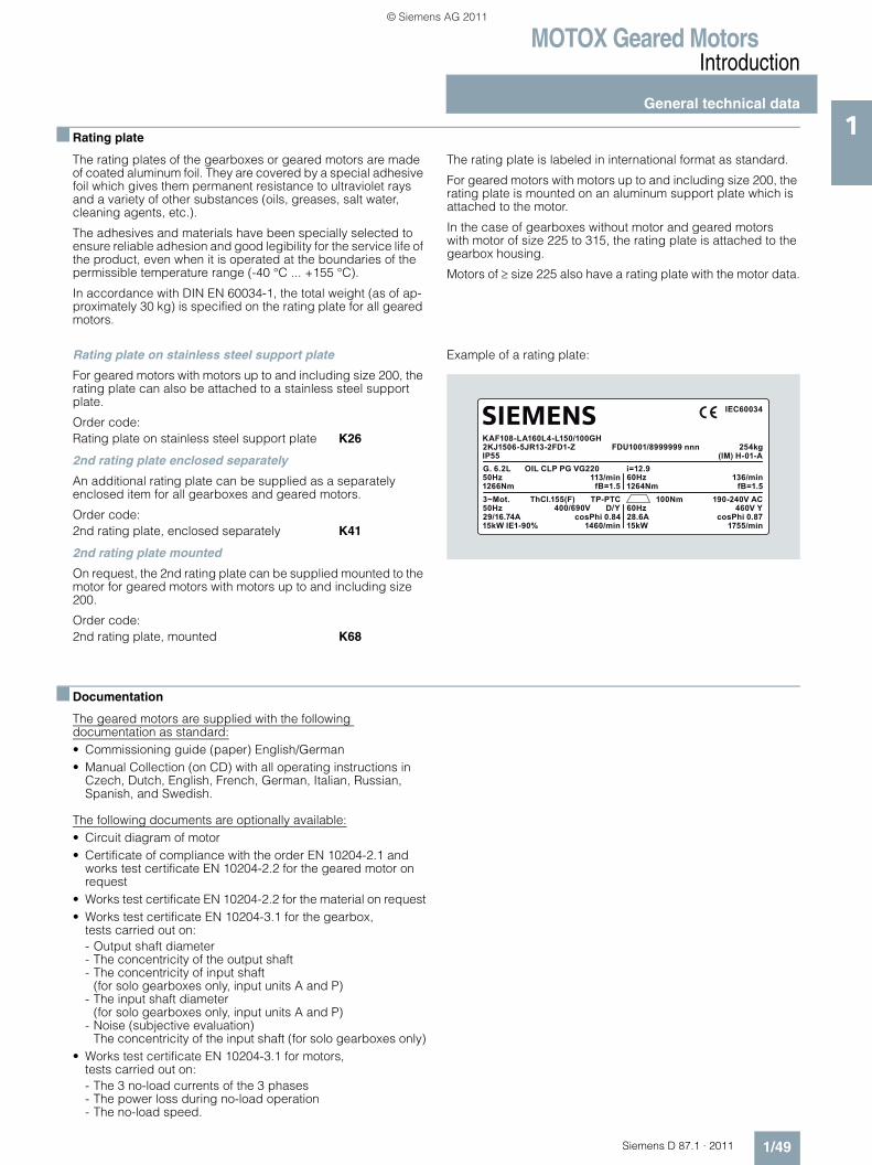
MOTOX Geared MotorsIntroduction
General technical data
1/49Siemens D 87.1 · 2011
1■ Rating plate
The rating plates of the gearboxes or geared motors are made of coated aluminum foil. They are covered by a special adhesive foil which gives them permanent resistance to ultraviolet rays and a variety of other substances (oils, greases, salt water, cleaning agents, etc.).
The adhesives and materials have been specially selected to ensure reliable adhesion and good legibility for the service life of the product, even when it is operated at the boundaries of the permissible temperature range (-40 °C ... +155 °C).
In accordance with DIN EN 60034-1, the total weight (as of ap-proximately 30 kg) is specified on the rating plate for all geared motors.
The rating plate is labeled in international format as standard.
For geared motors with motors up to and including size 200, the rating plate is mounted on an aluminum support plate which is attached to the motor.
In the case of gearboxes without motor and geared motors with motor of size 225 to 315, the rating plate is attached to the gearbox housing.
Motors of ≥ size 225 also have a rating plate with the motor data.
Rating plate on stainless steel support plate
For geared motors with motors up to and including size 200, the rating plate can also be attached to a stainless steel support plate.
Order code:Rating plate on stainless steel support plate K26
2nd rating plate enclosed separately
An additional rating plate can be supplied as a separately enclosed item for all gearboxes and geared motors.
Order code:2nd rating plate, enclosed separately K41
2nd rating plate mounted
On request, the 2nd rating plate can be supplied mounted to the motor for geared motors with motors up to and including size 200.
Order code:2nd rating plate, mounted K68
Example of a rating plate:
■ Documentation
The geared motors are supplied with the following documentation as standard:• Commissioning guide (paper) English/German• Manual Collection (on CD) with all operating instructions in
Czech, Dutch, English, French, German, Italian, Russian, Spanish, and Swedish.
The following documents are optionally available:• Circuit diagram of motor• Certificate of compliance with the order EN 10204-2.1 and
works test certificate EN 10204-2.2 for the geared motor on request
• Works test certificate EN 10204-2.2 for the material on request• Works test certificate EN 10204-3.1 for the gearbox,
tests carried out on:- Output shaft diameter- The concentricity of the output shaft- The concentricity of input shaft
(for solo gearboxes only, input units A and P)- The input shaft diameter
(for solo gearboxes only, input units A and P) - Noise (subjective evaluation)
The concentricity of the input shaft (for solo gearboxes only)• Works test certificate EN 10204-3.1 for motors,
tests carried out on:- The 3 no-load currents of the 3 phases- The power loss during no-load operation- The no-load speed.
SIEMENS
50Hz
50Hz29/16.74A15kW IE1-90%
cosPhi 0.84 28.6A60Hz
100Nm 190-240V AC460V Y
cosPhi 0.871460/min 15kW 1755/min
400/690V
1266Nm3~Mot. ThCl.155(F) TP-PTC
D/Y
113/minfB=1.5 1264Nm fB=1.5
KAF108-LA160L4-L150/100GH2KJ1506-5JR13-2FD1-ZIP55G. 6.2L OIL CLP PG VG220 i=12.9
60Hz 136/min
FDU1001/8999999 nnn 254kg
IEC60034
(IM) H-01-A
© Siemens AG 2011
MOTOX Geared MotorsIntroduction
Notes
1/50 Siemens D 87.1 · 2011
1
© Siemens AG 2011
Siemens D 87.1 · 2011
5Orientation
5/2 Overview5/5 Modular system
General technical data5/6 Permissible radial force
Geared motors up to 11 kW5/7 Selection and ordering data
Transmission ratios and maximum torques
5/25 Selection and ordering data
Mounting types5/43 Selection and ordering data
Shaft designs5/45 Selection and ordering data
Flange-mounted designs5/46 Selection and ordering data
Mounting types and mounting positions
5/47 Selection and ordering data
Special versions5/50 Lubricants5/50 Oil level control5/51 Gearbox ventilation5/51 Oil drain5/52 Sealing5/52 Hollow shaft cover (protection cover)5/53 Radially reinforced output shaft
bearings5/53 2nd output shaft extension
Dimensions5/54 Dimension drawing overview5/57 Dimension drawings
Helical worm geared motors
© Siemens AG 2011
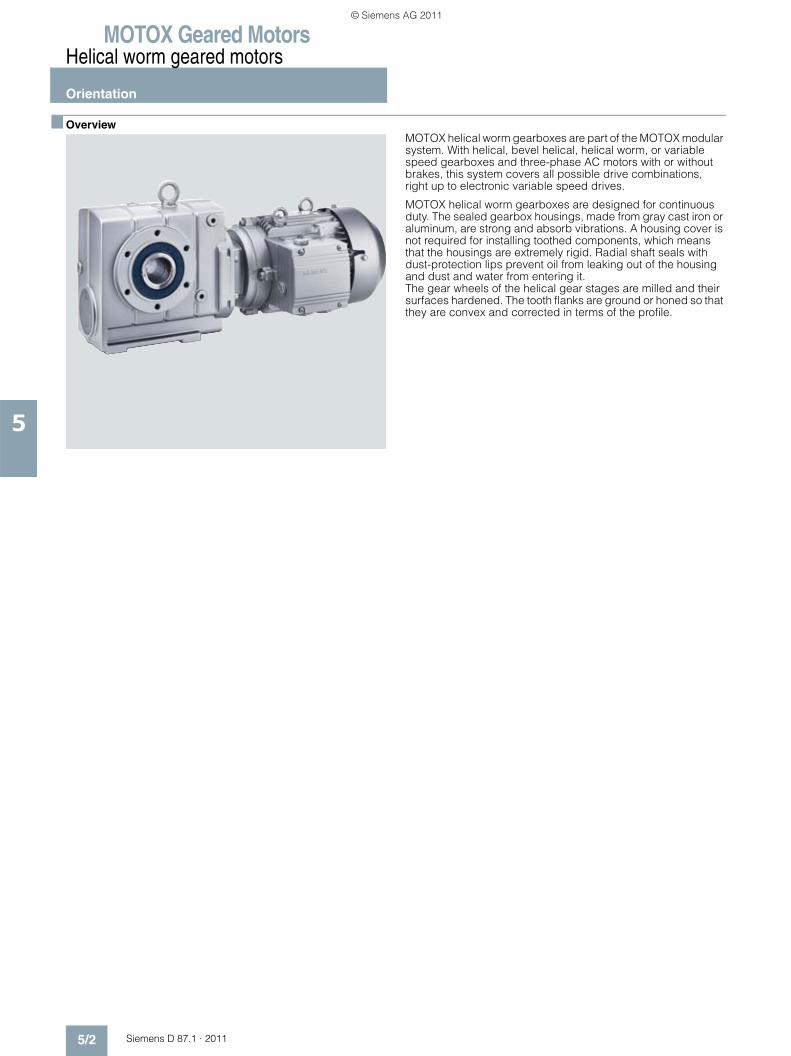
MOTOX Geared MotorsHelical worm geared motors
Orientation
5/2 Siemens D 87.1 · 2011
5
■ OverviewMOTOX helical worm gearboxes are part of the MOTOX modular system. With helical, bevel helical, helical worm, or variable speed gearboxes and three-phase AC motors with or without brakes, this system covers all possible drive combinations, right up to electronic variable speed drives.
MOTOX helical worm gearboxes are designed for continuous duty. The sealed gearbox housings, made from gray cast iron or aluminum, are strong and absorb vibrations. A housing cover is not required for installing toothed components, which means that the housings are extremely rigid. Radial shaft seals with dust-protection lips prevent oil from leaking out of the housing and dust and water from entering it. The gear wheels of the helical gear stages are milled and their surfaces hardened. The tooth flanks are ground or honed so that they are convex and corrected in terms of the profile.
© Siemens AG 2011
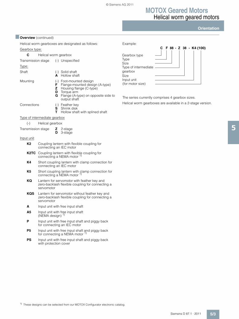
MOTOX Geared MotorsHelical worm geared motors
Orientation
5/3Siemens D 87.1 · 2011
5
■ Overview (continued)
Helical worm gearboxes are designated as follows:
Gearbox type:
C Helical worm gearbox
Transmission stage (-) Unspecified
Type:
Shaft (-) Solid shaftA Hollow shaft
Mounting (-) Foot-mounted designF Flange-mounted design (A-type)Z Housing flange (C-type)D Torque armG Flange (A-type) on opposite side to
output shaft
Connections (-) Feather keyS Shrink diskT Hollow shaft with splined shaft
Type of intermediate gearbox
(-) Helical gearbox
Transmission stage Z 2-stageD 3-stage
Input unit
K2 Coupling lantern with flexible coupling for connecting an IEC motor
K2TC Coupling lantern with flexible coupling for connecting a NEMA motor 1)
K4 Short coupling lantern with clamp connection for connecting an IEC motor
K5 Short coupling lantern with clamp connection for connecting a NEMA motor 1)
KQ Lantern for servomotor with feather key and zero-backlash flexible coupling for connecting aservomotor
KQS Lantern for servomotor without feather key andzero-backlash flexible coupling for connecting a servomotor
A Input unit with free input shaft
A5 Input unit with free input shaft (NEMA design) 1)
P Input unit with free input shaft and piggy back for connecting an IEC motor
P5 Input unit with free input shaft and piggy back for connecting a NEMA motor 1)
PS Input unit with free input shaft and piggy back with protection cover
Example:
The series currently comprises 4 gearbox sizes.
Helical worm gearboxes are available in a 2-stage version.
1) These designs can be selected from our MOTOX Configurator electronic catalog.
Gearbox typeTypeSizeType of intermediate
SizeInput unit(for motor size)
K4C 88 - Z 38F - (100)
gearbox
© Siemens AG 2011
MOTOX Geared MotorsHelical worm geared motors
Orientation
5/4 Siemens D 87.1 · 2011
5
■ Overview (continued)
Worm and wheel sets with CAVEX gearing
CAVEX concave-profile worm and wheel sets are used for size 38 and above. The concave-profile cylindrical worm with its en-veloping worm wheel is very much different to conventional de-signs. The worm threads have a concave profile instead of an in-volute or convex one.
The concave-profile teeth are subject to only low specific tooth pressure. The retention of a separating oil film between the tooth flanks is facilitated in particular, as the hollow flanks are in con-tact with convex mating flanks. Therefore, profile contact is much more favorable than in conventional gear teeth systems.
The concave-profile teeth provide a particularly favorable posi-tion for the instantaneous axes, which extend mainly at right an-gles to the sliding direction. This assists the build-up of lubricat-ing pressure, i.e. the generation of an oil film between the tooth flanks.
The tooth flanks on new gearboxes will not yet be fully smoothed, meaning that the friction angle will be greater and efficiency lower during initial operation. The smaller the lead angle or, in other words, the higher the transmission ratio, the more pro-nounced the effect. The run-in procedure should take approxi-mately 24 to 30 hours of operation at full load.
Starting efficiency is never as great as the efficiency at operating speed. This fact should be taken into account when starting a machine at full load, depending on the starting characteristics of the motor.
Attention: In respect of torque driving back from the output shaft, please take into account the reduced gear tooth efficiency η ' = 2 - 1/η, particularly with high transmission ratios of the worm gear stage (η = efficiency with driving worm).
Self-locking only occurs at high worm transmission ratios, which are not used for sizes 28 to 88.
© Siemens AG 2011
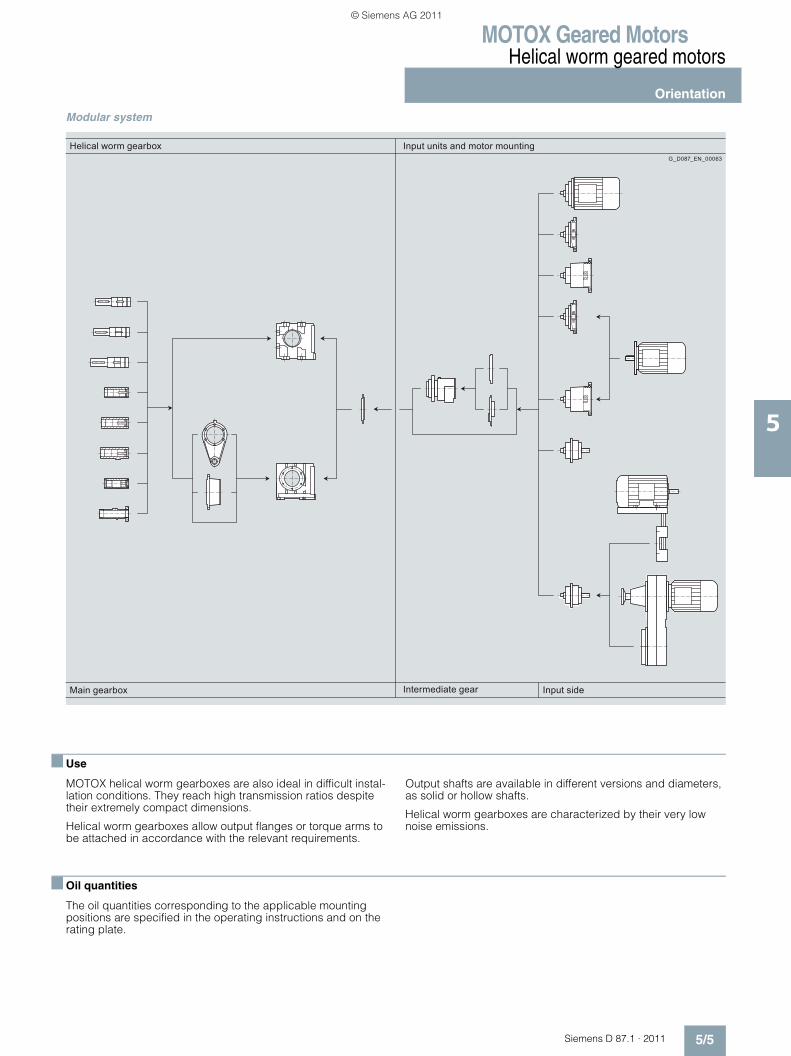
MOTOX Geared MotorsHelical worm geared motors
Orientation
5/5Siemens D 87.1 · 2011
5
Modular system
■ Use
MOTOX helical worm gearboxes are also ideal in difficult instal-lation conditions. They reach high transmission ratios despite their extremely compact dimensions.
Helical worm gearboxes allow output flanges or torque arms to be attached in accordance with the relevant requirements.
Output shafts are available in different versions and diameters, as solid or hollow shafts.
Helical worm gearboxes are characterized by their very low noise emissions.
■ Oil quantities
The oil quantities corresponding to the applicable mounting positions are specified in the operating instructions and on the rating plate.
Helical worm gearbox
Main gearbox
Input units and motor mounting
Intermediate gear Input side
G_D087_EN_00063
© Siemens AG 2011
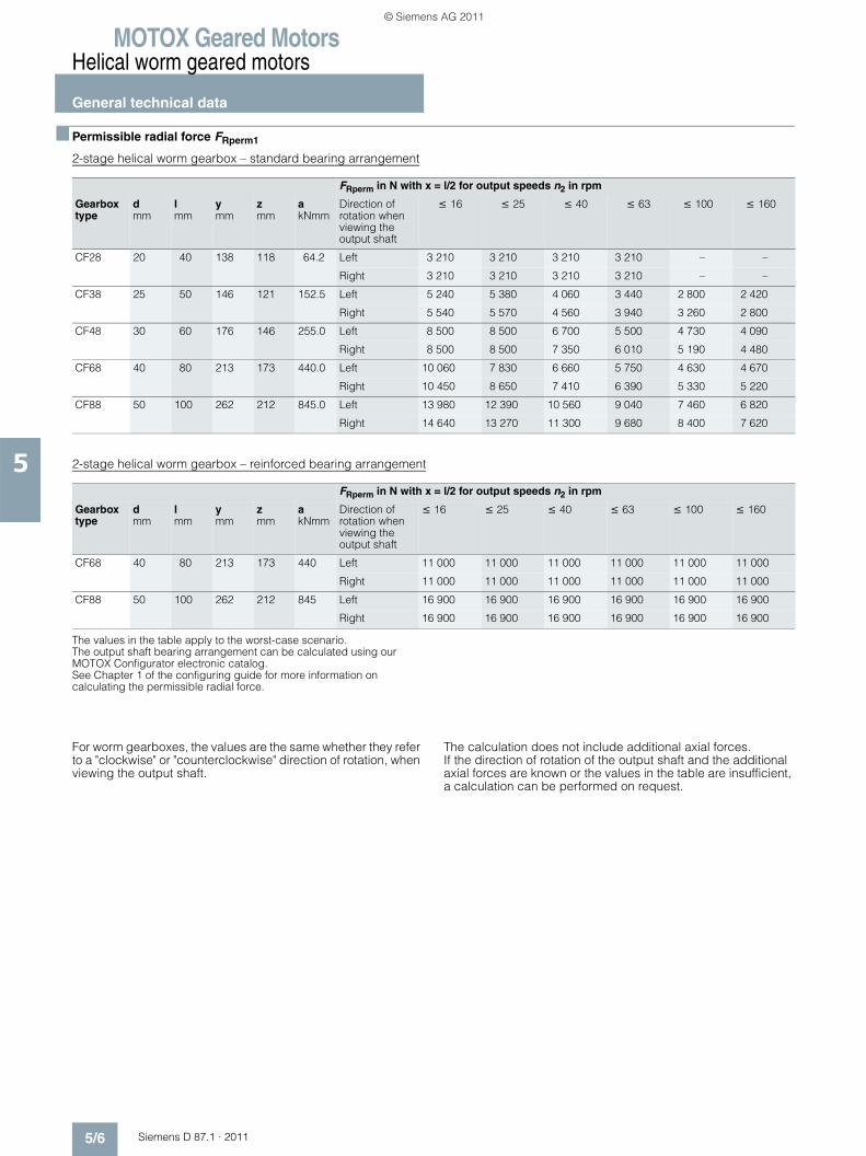
MOTOX Geared MotorsHelical worm geared motors
General technical data
5/6 Siemens D 87.1 · 2011
5
■ Permissible radial force FRperm1
2-stage helical worm gearbox – standard bearing arrangement
2-stage helical worm gearbox – reinforced bearing arrangement
The values in the table apply to the worst-case scenario. The output shaft bearing arrangement can be calculated using our MOTOX Configurator electronic catalog.See Chapter 1 of the configuring guide for more information on calculating the permissible radial force.
For worm gearboxes, the values are the same whether they refer to a "clockwise" or "counterclockwise" direction of rotation, when viewing the output shaft.
The calculation does not include additional axial forces. If the direction of rotation of the output shaft and the additional axial forces are known or the values in the table are insufficient, a calculation can be performed on request.
FRperm in N with x = l/2 for output speeds n2 in rpm
Gearbox type
d mm
l mm
y mm
z mm
a kNmm
Direction of rotation when viewing the output shaft
≤ 16 ≤ 25 ≤ 40 ≤ 63 ≤ 100 ≤ 160
CF28 20 40 138 118 64.2 Left 3 210 3 210 3 210 3 210 – –
Right 3 210 3 210 3 210 3 210 – –
CF38 25 50 146 121 152.5 Left 5 240 5 380 4 060 3 440 2 800 2 420
Right 5 540 5 570 4 560 3 940 3 260 2 800
CF48 30 60 176 146 255.0 Left 8 500 8 500 6 700 5 500 4 730 4 090
Right 8 500 8 500 7 350 6 010 5 190 4 480
CF68 40 80 213 173 440.0 Left 10 060 7 830 6 660 5 750 4 630 4 670
Right 10 450 8 650 7 410 6 390 5 330 5 220
CF88 50 100 262 212 845.0 Left 13 980 12 390 10 560 9 040 7 460 6 820
Right 14 640 13 270 11 300 9 680 8 400 7 620
FRperm in N with x = l/2 for output speeds n2 in rpm
Gearbox type
d mm
l mm
y mm
z mm
a kNmm
Direction of rotation when viewing the output shaft
≤ 16 ≤ 25 ≤ 40 ≤ 63 ≤ 100 ≤ 160
CF68 40 80 213 173 440 Left 11 000 11 000 11 000 11 000 11 000 11 000
Right 11 000 11 000 11 000 11 000 11 000 11 000
CF88 50 100 262 212 845 Left 16 900 16 900 16 900 16 900 16 900 16 900
Right 16 900 16 900 16 900 16 900 16 900 16 900
© Siemens AG 2011
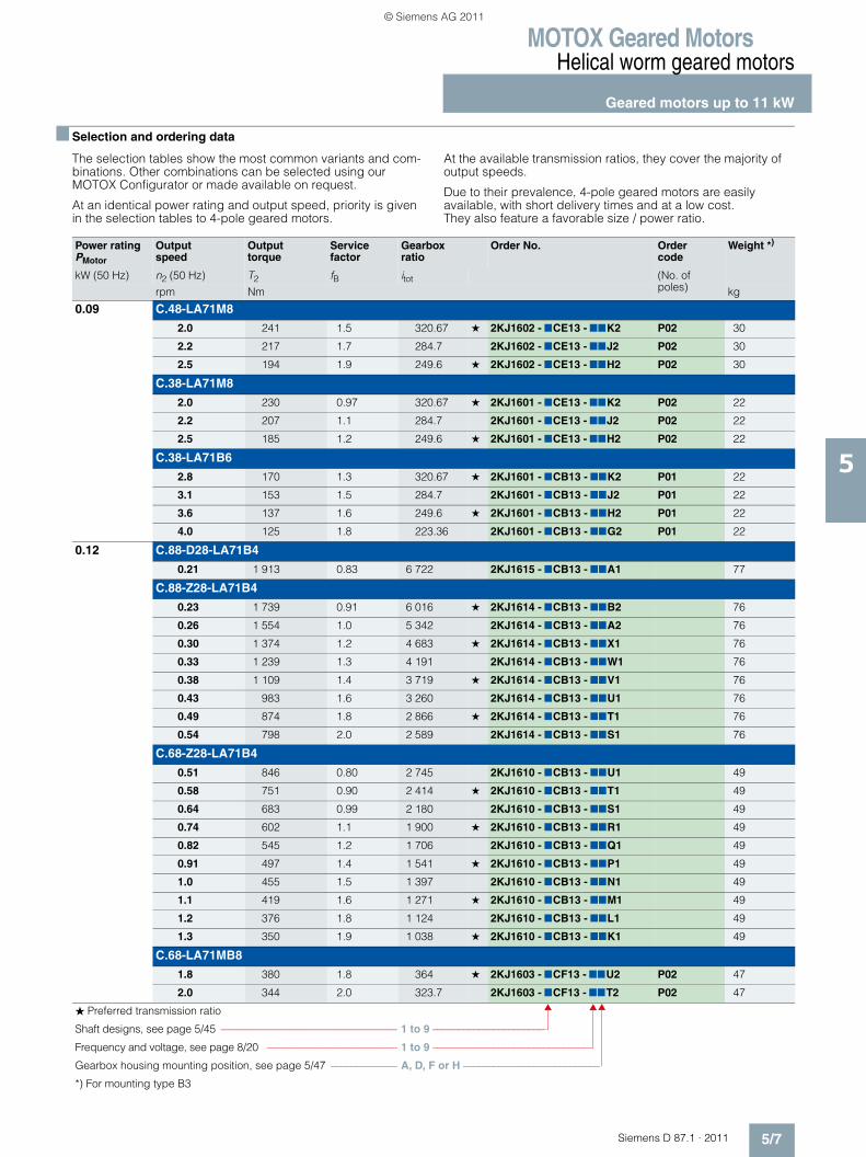
MOTOX Geared MotorsHelical worm geared motors
Geared motors up to 11 kW
5/7Siemens D 87.1 · 2011
5
■ Selection and ordering data
The selection tables show the most common variants and com-binations. Other combinations can be selected using our MOTOX Configurator or made available on request.
At an identical power rating and output speed, priority is given in the selection tables to 4-pole geared motors.
At the available transmission ratios, they cover the majority of output speeds.
Due to their prevalence, 4-pole geared motors are easily available, with short delivery times and at a low cost. They also feature a favorable size / power ratio.
Power ratingPMotor
Output speed
Output torque
Service factor
Gearbox ratio
Order No. Order code
Weight *)
kW (50 Hz) n2 (50 Hz) T2 fB itot (No. of poles)rpm Nm kg
0.09 C.48-LA71M8
2.0 241 1.5 320.67 ★ 2KJ1602 - 7CE13 - 77K2 P02 30
2.2 217 1.7 284.7 2KJ1602 - 7CE13 - 77J2 P02 30
2.5 194 1.9 249.6 ★ 2KJ1602 - 7CE13 - 77H2 P02 30
C.38-LA71M8
2.0 230 0.97 320.67 ★ 2KJ1601 - 7CE13 - 77K2 P02 22
2.2 207 1.1 284.7 2KJ1601 - 7CE13 - 77J2 P02 22
2.5 185 1.2 249.6 ★ 2KJ1601 - 7CE13 - 77H2 P02 22
C.38-LA71B6
2.8 170 1.3 320.67 ★ 2KJ1601 - 7CB13 - 77K2 P01 22
3.1 153 1.5 284.7 2KJ1601 - 7CB13 - 77J2 P01 22
3.6 137 1.6 249.6 ★ 2KJ1601 - 7CB13 - 77H2 P01 22
4.0 125 1.8 223.36 2KJ1601 - 7CB13 - 77G2 P01 22
0.12 C.88-D28-LA71B4
0.21 1 913 0.83 6 722 2KJ1615 - 7CB13 - 77A1 77
C.88-Z28-LA71B4
0.23 1 739 0.91 6 016 ★ 2KJ1614 - 7CB13 - 77B2 76
0.26 1 554 1.0 5 342 2KJ1614 - 7CB13 - 77A2 76
0.30 1 374 1.2 4 683 ★ 2KJ1614 - 7CB13 - 77X1 76
0.33 1 239 1.3 4 191 2KJ1614 - 7CB13 - 77W1 76
0.38 1 109 1.4 3 719 ★ 2KJ1614 - 7CB13 - 77V1 76
0.43 983 1.6 3 260 2KJ1614 - 7CB13 - 77U1 76
0.49 874 1.8 2 866 ★ 2KJ1614 - 7CB13 - 77T1 76
0.54 798 2.0 2 589 2KJ1614 - 7CB13 - 77S1 76
C.68-Z28-LA71B4
0.51 846 0.80 2 745 2KJ1610 - 7CB13 - 77U1 49
0.58 751 0.90 2 414 ★ 2KJ1610 - 7CB13 - 77T1 49
0.64 683 0.99 2 180 2KJ1610 - 7CB13 - 77S1 49
0.74 602 1.1 1 900 ★ 2KJ1610 - 7CB13 - 77R1 49
0.82 545 1.2 1 706 2KJ1610 - 7CB13 - 77Q1 49
0.91 497 1.4 1 541 ★ 2KJ1610 - 7CB13 - 77P1 49
1.0 455 1.5 1 397 2KJ1610 - 7CB13 - 77N1 49
1.1 419 1.6 1 271 ★ 2KJ1610 - 7CB13 - 77M1 49
1.2 376 1.8 1 124 2KJ1610 - 7CB13 - 77L1 49
1.3 350 1.9 1 038 ★ 2KJ1610 - 7CB13 - 77K1 49
C.68-LA71MB8
1.8 380 1.8 364 ★ 2KJ1603 - 7CF13 - 77U2 P02 47
2.0 344 2.0 323.7 2KJ1603 - 7CF13 - 77T2 P02 47
� Preferred transmission ratio
Shaft designs, see page 5/45 ––––––––––––––––––––––––––––––––– 1 to 9 ––––––––––––––––––––––
Frequency and voltage, see page 8/20 ––––––––––––––––––––––––– 1 to 9 –––––––––––––––––––––––––––––––
Gearbox housing mounting position, see page 5/47 ––––––––––––– A, D, F or H –––––––––––––––––––––––––––
*) For mounting type B3
© Siemens AG 2011
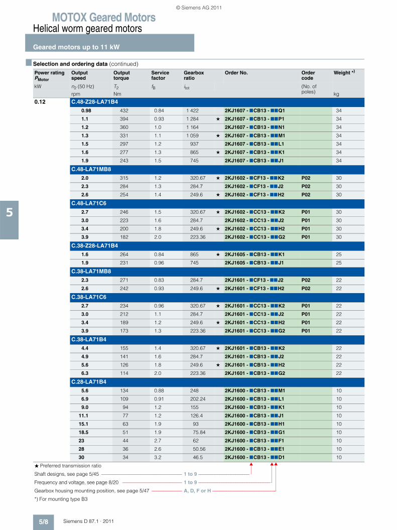
MOTOX Geared MotorsHelical worm geared motors
Geared motors up to 11 kW
5/8 Siemens D 87.1 · 2011
5
■ Selection and ordering data (continued)
Power ratingPMotor
Output speed
Output torque
Service factor
Gearbox ratio
Order No. Order code
Weight *)
kW n2 (50 Hz) T2 fB itot (No. of poles)rpm Nm kg
0.12 C.48-Z28-LA71B4
0.98 432 0.84 1 422 2KJ1607 - 7CB13 - 77Q1 34
1.1 394 0.93 1 284 ★ 2KJ1607 - 7CB13 - 77P1 34
1.2 360 1.0 1 164 2KJ1607 - 7CB13 - 77N1 34
1.3 331 1.1 1 059 ★ 2KJ1607 - 7CB13 - 77M1 34
1.5 297 1.2 937 2KJ1607 - 7CB13 - 77L1 34
1.6 277 1.3 865 ★ 2KJ1607 - 7CB13 - 77K1 34
1.9 243 1.5 745 2KJ1607 - 7CB13 - 77J1 34
C.48-LA71MB8
2.0 315 1.2 320.67 ★ 2KJ1602 - 7CF13 - 77K2 P02 30
2.3 284 1.3 284.7 2KJ1602 - 7CF13 - 77J2 P02 30
2.6 254 1.4 249.6 ★ 2KJ1602 - 7CF13 - 77H2 P02 30
C.48-LA71C6
2.7 246 1.5 320.67 ★ 2KJ1602 - 7CC13 - 77K2 P01 30
3.0 223 1.6 284.7 2KJ1602 - 7CC13 - 77J2 P01 30
3.4 200 1.8 249.6 ★ 2KJ1602 - 7CC13 - 77H2 P01 30
3.9 182 2.0 223.36 2KJ1602 - 7CC13 - 77G2 P01 30
C.38-Z28-LA71B4
1.6 264 0.84 865 ★ 2KJ1605 - 7CB13 - 77K1 25
1.9 231 0.96 745 2KJ1605 - 7CB13 - 77J1 25
C.38-LA71MB8
2.3 271 0.83 284.7 2KJ1601 - 7CF13 - 77J2 P02 22
2.6 242 0.93 249.6 ★ 2KJ1601 - 7CF13 - 77H2 P02 22
C.38-LA71C6
2.7 234 0.96 320.67 ★ 2KJ1601 - 7CC13 - 77K2 P01 22
3.0 212 1.1 284.7 2KJ1601 - 7CC13 - 77J2 P01 22
3.4 189 1.2 249.6 ★ 2KJ1601 - 7CC13 - 77H2 P01 22
3.9 173 1.3 223.36 2KJ1601 - 7CC13 - 77G2 P01 22
C.38-LA71B4
4.4 155 1.4 320.67 ★ 2KJ1601 - 7CB13 - 77K2 22
4.9 141 1.6 284.7 2KJ1601 - 7CB13 - 77J2 22
5.6 126 1.8 249.6 ★ 2KJ1601 - 7CB13 - 77H2 22
6.3 114 2.0 223.36 2KJ1601 - 7CB13 - 77G2 22
C.28-LA71B4
5.6 134 0.88 248 2KJ1600 - 7CB13 - 77M1 10
6.9 109 0.91 202.24 2KJ1600 - 7CB13 - 77L1 10
9.0 94 1.2 155 2KJ1600 - 7CB13 - 77K1 10
11.1 77 1.2 126.4 2KJ1600 - 7CB13 - 77J1 10
15.1 63 1.9 93 2KJ1600 - 7CB13 - 77H1 10
18.5 51 1.9 75.84 2KJ1600 - 7CB13 - 77G1 10
23 44 2.7 62 2KJ1600 - 7CB13 - 77F1 10
28 36 2.6 50.56 2KJ1600 - 7CB13 - 77E1 10
30 34 3.2 46.5 2KJ1600 - 7CB13 - 77D1 10
� Preferred transmission ratio
Shaft designs, see page 5/45 ––––––––––––––––––––––––––––––––– 1 to 9 ––––––––––––––––––––––
Frequency and voltage, see page 8/20 ––––––––––––––––––––––––– 1 to 9 –––––––––––––––––––––––––––––––
Gearbox housing mounting position, see page 5/47 ––––––––––––– A, D, F or H –––––––––––––––––––––––––––
*) For mounting type B3
© Siemens AG 2011
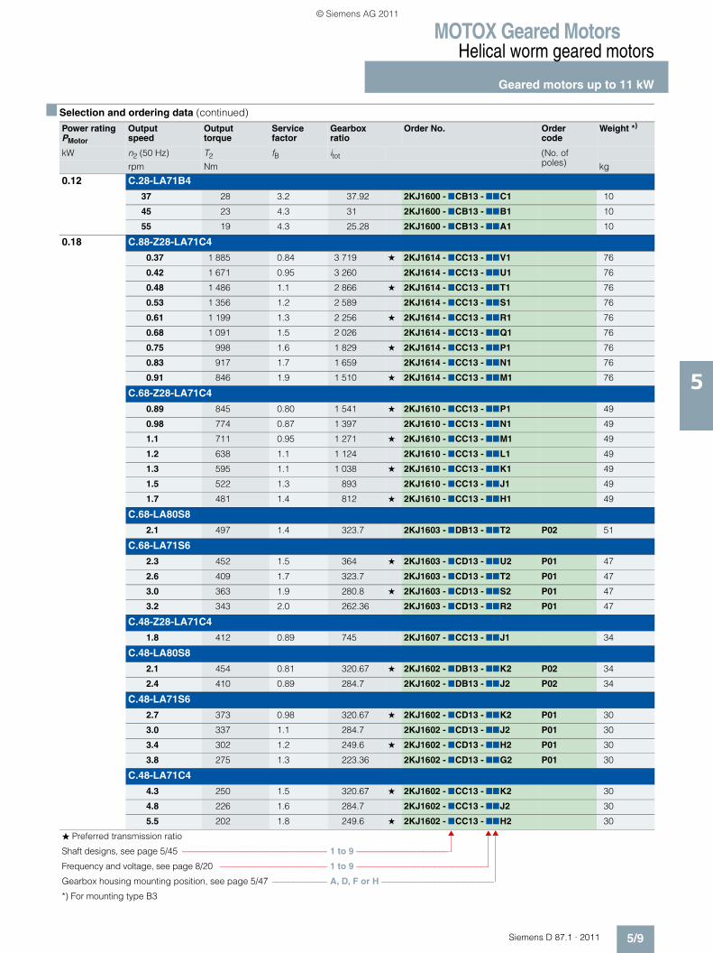
MOTOX Geared MotorsHelical worm geared motors
Geared motors up to 11 kW
5/9Siemens D 87.1 · 2011
5
0.12 C.28-LA71B4
37 28 3.2 37.92 2KJ1600 - 7CB13 - 77C1 10
45 23 4.3 31 2KJ1600 - 7CB13 - 77B1 10
55 19 4.3 25.28 2KJ1600 - 7CB13 - 77A1 10
0.18 C.88-Z28-LA71C4
0.37 1 885 0.84 3 719 ★ 2KJ1614 - 7CC13 - 77V1 76
0.42 1 671 0.95 3 260 2KJ1614 - 7CC13 - 77U1 76
0.48 1 486 1.1 2 866 ★ 2KJ1614 - 7CC13 - 77T1 76
0.53 1 356 1.2 2 589 2KJ1614 - 7CC13 - 77S1 76
0.61 1 199 1.3 2 256 ★ 2KJ1614 - 7CC13 - 77R1 76
0.68 1 091 1.5 2 026 2KJ1614 - 7CC13 - 77Q1 76
0.75 998 1.6 1 829 ★ 2KJ1614 - 7CC13 - 77P1 76
0.83 917 1.7 1 659 2KJ1614 - 7CC13 - 77N1 76
0.91 846 1.9 1 510 ★ 2KJ1614 - 7CC13 - 77M1 76
C.68-Z28-LA71C4
0.89 845 0.80 1 541 ★ 2KJ1610 - 7CC13 - 77P1 49
0.98 774 0.87 1 397 2KJ1610 - 7CC13 - 77N1 49
1.1 711 0.95 1 271 ★ 2KJ1610 - 7CC13 - 77M1 49
1.2 638 1.1 1 124 2KJ1610 - 7CC13 - 77L1 49
1.3 595 1.1 1 038 ★ 2KJ1610 - 7CC13 - 77K1 49
1.5 522 1.3 893 2KJ1610 - 7CC13 - 77J1 49
1.7 481 1.4 812 ★ 2KJ1610 - 7CC13 - 77H1 49
C.68-LA80S8
2.1 497 1.4 323.7 2KJ1603 - 7DB13 - 77T2 P02 51
C.68-LA71S6
2.3 452 1.5 364 ★ 2KJ1603 - 7CD13 - 77U2 P01 47
2.6 409 1.7 323.7 2KJ1603 - 7CD13 - 77T2 P01 47
3.0 363 1.9 280.8 ★ 2KJ1603 - 7CD13 - 77S2 P01 47
3.2 343 2.0 262.36 2KJ1603 - 7CD13 - 77R2 P01 47
C.48-Z28-LA71C4
1.8 412 0.89 745 2KJ1607 - 7CC13 - 77J1 34
C.48-LA80S8
2.1 454 0.81 320.67 ★ 2KJ1602 - 7DB13 - 77K2 P02 34
2.4 410 0.89 284.7 2KJ1602 - 7DB13 - 77J2 P02 34
C.48-LA71S6
2.7 373 0.98 320.67 ★ 2KJ1602 - 7CD13 - 77K2 P01 30
3.0 337 1.1 284.7 2KJ1602 - 7CD13 - 77J2 P01 30
3.4 302 1.2 249.6 ★ 2KJ1602 - 7CD13 - 77H2 P01 30
3.8 275 1.3 223.36 2KJ1602 - 7CD13 - 77G2 P01 30
C.48-LA71C4
4.3 250 1.5 320.67 ★ 2KJ1602 - 7CC13 - 77K2 30
4.8 226 1.6 284.7 2KJ1602 - 7CC13 - 77J2 30
5.5 202 1.8 249.6 ★ 2KJ1602 - 7CC13 - 77H2 30
■ Selection and ordering data (continued)
Power ratingPMotor
Output speed
Output torque
Service factor
Gearbox ratio
Order No. Order code
Weight *)
kW n2 (50 Hz) T2 fB itot (No. of poles)rpm Nm kg
� Preferred transmission ratio
Shaft designs, see page 5/45 ––––––––––––––––––––––––––––––––– 1 to 9 ––––––––––––––––––––––
Frequency and voltage, see page 8/20 ––––––––––––––––––––––––– 1 to 9 –––––––––––––––––––––––––––––––
Gearbox housing mounting position, see page 5/47 ––––––––––––– A, D, F or H –––––––––––––––––––––––––––
*) For mounting type B3
© Siemens AG 2011
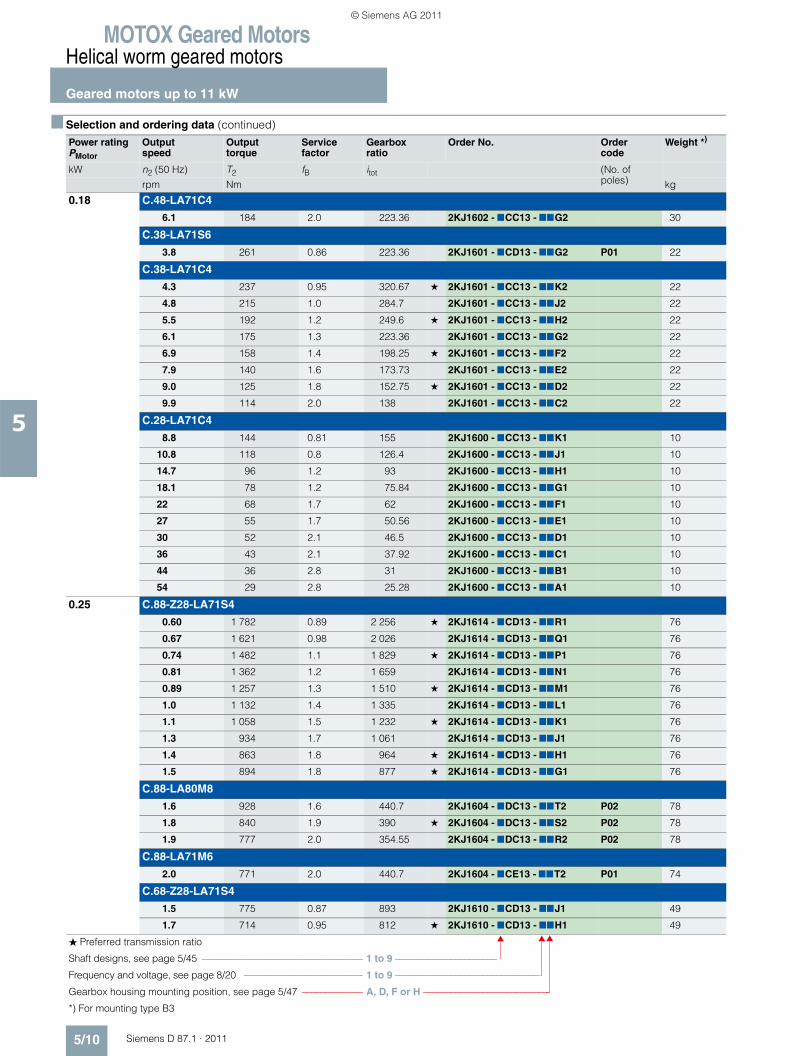
MOTOX Geared MotorsHelical worm geared motors
Geared motors up to 11 kW
5/10 Siemens D 87.1 · 2011
5
0.18 C.48-LA71C4
6.1 184 2.0 223.36 2KJ1602 - 7CC13 - 77G2 30
C.38-LA71S6
3.8 261 0.86 223.36 2KJ1601 - 7CD13 - 77G2 P01 22
C.38-LA71C4
4.3 237 0.95 320.67 ★ 2KJ1601 - 7CC13 - 77K2 22
4.8 215 1.0 284.7 2KJ1601 - 7CC13 - 77J2 22
5.5 192 1.2 249.6 ★ 2KJ1601 - 7CC13 - 77H2 22
6.1 175 1.3 223.36 2KJ1601 - 7CC13 - 77G2 22
6.9 158 1.4 198.25 ★ 2KJ1601 - 7CC13 - 77F2 22
7.9 140 1.6 173.73 2KJ1601 - 7CC13 - 77E2 22
9.0 125 1.8 152.75 ★ 2KJ1601 - 7CC13 - 77D2 22
9.9 114 2.0 138 2KJ1601 - 7CC13 - 77C2 22
C.28-LA71C4
8.8 144 0.81 155 2KJ1600 - 7CC13 - 77K1 10
10.8 118 0.8 126.4 2KJ1600 - 7CC13 - 77J1 10
14.7 96 1.2 93 2KJ1600 - 7CC13 - 77H1 10
18.1 78 1.2 75.84 2KJ1600 - 7CC13 - 77G1 10
22 68 1.7 62 2KJ1600 - 7CC13 - 77F1 10
27 55 1.7 50.56 2KJ1600 - 7CC13 - 77E1 10
30 52 2.1 46.5 2KJ1600 - 7CC13 - 77D1 10
36 43 2.1 37.92 2KJ1600 - 7CC13 - 77C1 10
44 36 2.8 31 2KJ1600 - 7CC13 - 77B1 10
54 29 2.8 25.28 2KJ1600 - 7CC13 - 77A1 10
0.25 C.88-Z28-LA71S4
0.60 1 782 0.89 2 256 ★ 2KJ1614 - 7CD13 - 77R1 76
0.67 1 621 0.98 2 026 2KJ1614 - 7CD13 - 77Q1 76
0.74 1 482 1.1 1 829 ★ 2KJ1614 - 7CD13 - 77P1 76
0.81 1 362 1.2 1 659 2KJ1614 - 7CD13 - 77N1 76
0.89 1 257 1.3 1 510 ★ 2KJ1614 - 7CD13 - 77M1 76
1.0 1 132 1.4 1 335 2KJ1614 - 7CD13 - 77L1 76
1.1 1 058 1.5 1 232 ★ 2KJ1614 - 7CD13 - 77K1 76
1.3 934 1.7 1 061 2KJ1614 - 7CD13 - 77J1 76
1.4 863 1.8 964 ★ 2KJ1614 - 7CD13 - 77H1 76
1.5 894 1.8 877 ★ 2KJ1614 - 7CD13 - 77G1 76
C.88-LA80M8
1.6 928 1.6 440.7 2KJ1604 - 7DC13 - 77T2 P02 78
1.8 840 1.9 390 ★ 2KJ1604 - 7DC13 - 77S2 P02 78
1.9 777 2.0 354.55 2KJ1604 - 7DC13 - 77R2 P02 78
C.88-LA71M6
2.0 771 2.0 440.7 2KJ1604 - 7CE13 - 77T2 P01 74
C.68-Z28-LA71S4
1.5 775 0.87 893 2KJ1610 - 7CD13 - 77J1 49
1.7 714 0.95 812 ★ 2KJ1610 - 7CD13 - 77H1 49
■ Selection and ordering data (continued)
Power ratingPMotor
Output speed
Output torque
Service factor
Gearbox ratio
Order No. Order code
Weight *)
kW n2 (50 Hz) T2 fB itot (No. of poles)rpm Nm kg
� Preferred transmission ratio
Shaft designs, see page 5/45 ––––––––––––––––––––––––––––––––– 1 to 9 ––––––––––––––––––––––
Frequency and voltage, see page 8/20 ––––––––––––––––––––––––– 1 to 9 –––––––––––––––––––––––––––––––
Gearbox housing mounting position, see page 5/47 ––––––––––––– A, D, F or H –––––––––––––––––––––––––––
*) For mounting type B3
© Siemens AG 2011
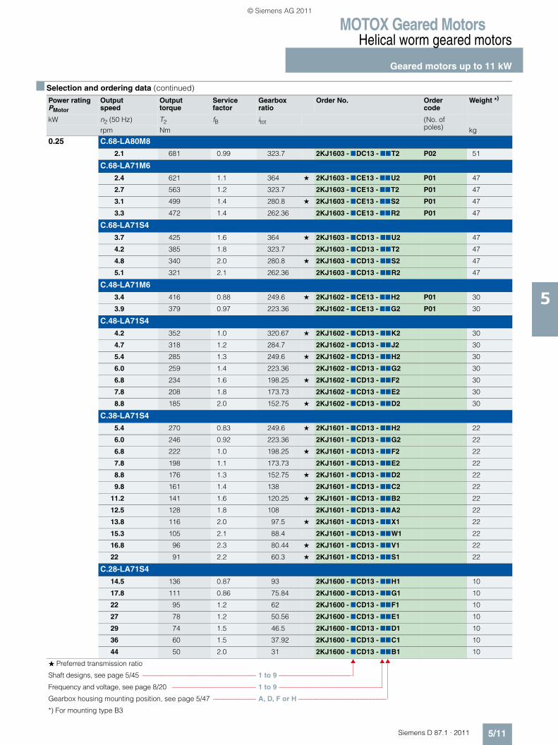
MOTOX Geared MotorsHelical worm geared motors
Geared motors up to 11 kW
5/11Siemens D 87.1 · 2011
5
0.25 C.68-LA80M8
2.1 681 0.99 323.7 2KJ1603 - 7DC13 - 77T2 P02 51
C.68-LA71M6
2.4 621 1.1 364 ★ 2KJ1603 - 7CE13 - 77U2 P01 47
2.7 563 1.2 323.7 2KJ1603 - 7CE13 - 77T2 P01 47
3.1 499 1.4 280.8 ★ 2KJ1603 - 7CE13 - 77S2 P01 47
3.3 472 1.4 262.36 2KJ1603 - 7CE13 - 77R2 P01 47
C.68-LA71S4
3.7 425 1.6 364 ★ 2KJ1603 - 7CD13 - 77U2 47
4.2 385 1.8 323.7 2KJ1603 - 7CD13 - 77T2 47
4.8 340 2.0 280.8 ★ 2KJ1603 - 7CD13 - 77S2 47
5.1 321 2.1 262.36 2KJ1603 - 7CD13 - 77R2 47
C.48-LA71M6
3.4 416 0.88 249.6 ★ 2KJ1602 - 7CE13 - 77H2 P01 30
3.9 379 0.97 223.36 2KJ1602 - 7CE13 - 77G2 P01 30
C.48-LA71S4
4.2 352 1.0 320.67 ★ 2KJ1602 - 7CD13 - 77K2 30
4.7 318 1.2 284.7 2KJ1602 - 7CD13 - 77J2 30
5.4 285 1.3 249.6 ★ 2KJ1602 - 7CD13 - 77H2 30
6.0 259 1.4 223.36 2KJ1602 - 7CD13 - 77G2 30
6.8 234 1.6 198.25 ★ 2KJ1602 - 7CD13 - 77F2 30
7.8 208 1.8 173.73 2KJ1602 - 7CD13 - 77E2 30
8.8 185 2.0 152.75 ★ 2KJ1602 - 7CD13 - 77D2 30
C.38-LA71S4
5.4 270 0.83 249.6 ★ 2KJ1601 - 7CD13 - 77H2 22
6.0 246 0.92 223.36 2KJ1601 - 7CD13 - 77G2 22
6.8 222 1.0 198.25 ★ 2KJ1601 - 7CD13 - 77F2 22
7.8 198 1.1 173.73 2KJ1601 - 7CD13 - 77E2 22
8.8 176 1.3 152.75 ★ 2KJ1601 - 7CD13 - 77D2 22
9.8 161 1.4 138 2KJ1601 - 7CD13 - 77C2 22
11.2 141 1.6 120.25 ★ 2KJ1601 - 7CD13 - 77B2 22
12.5 128 1.8 108 2KJ1601 - 7CD13 - 77A2 22
13.8 116 2.0 97.5 ★ 2KJ1601 - 7CD13 - 77X1 22
15.3 105 2.1 88.4 2KJ1601 - 7CD13 - 77W1 22
16.8 96 2.3 80.44 ★ 2KJ1601 - 7CD13 - 77V1 22
22 91 2.2 60.3 ★ 2KJ1601 - 7CD13 - 77S1 22
C.28-LA71S4
14.5 136 0.87 93 2KJ1600 - 7CD13 - 77H1 10
17.8 111 0.86 75.84 2KJ1600 - 7CD13 - 77G1 10
22 95 1.2 62 2KJ1600 - 7CD13 - 77F1 10
27 78 1.2 50.56 2KJ1600 - 7CD13 - 77E1 10
29 74 1.5 46.5 2KJ1600 - 7CD13 - 77D1 10
36 60 1.5 37.92 2KJ1600 - 7CD13 - 77C1 10
44 50 2.0 31 2KJ1600 - 7CD13 - 77B1 10
■ Selection and ordering data (continued)
Power ratingPMotor
Output speed
Output torque
Service factor
Gearbox ratio
Order No. Order code
Weight *)
kW n2 (50 Hz) T2 fB itot (No. of poles)rpm Nm kg
� Preferred transmission ratio
Shaft designs, see page 5/45 ––––––––––––––––––––––––––––––––– 1 to 9 ––––––––––––––––––––––
Frequency and voltage, see page 8/20 ––––––––––––––––––––––––– 1 to 9 –––––––––––––––––––––––––––––––
Gearbox housing mounting position, see page 5/47 ––––––––––––– A, D, F or H –––––––––––––––––––––––––––
*) For mounting type B3
© Siemens AG 2011
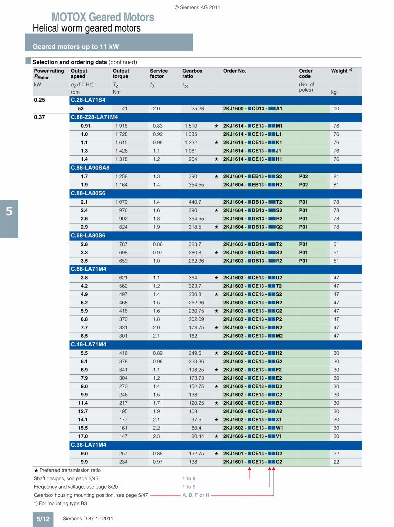
MOTOX Geared MotorsHelical worm geared motors
Geared motors up to 11 kW
5/12 Siemens D 87.1 · 2011
5
0.25 C.28-LA71S4
53 41 2.0 25.28 2KJ1600 - 7CD13 - 77A1 10
0.37 C.88-Z28-LA71M4
0.91 1 918 0.83 1 510 ★ 2KJ1614 - 7CE13 - 77M1 76
1.0 1 728 0.92 1 335 2KJ1614 - 7CE13 - 77L1 76
1.1 1 615 0.98 1 232 ★ 2KJ1614 - 7CE13 - 77K1 76
1.3 1 426 1.1 1 061 2KJ1614 - 7CE13 - 77J1 76
1.4 1 318 1.2 964 ★ 2KJ1614 - 7CE13 - 77H1 76
C.88-LA90SA8
1.7 1 258 1.3 390 ★ 2KJ1604 - 7EB13 - 77S2 P02 81
1.9 1 164 1.4 354.55 2KJ1604 - 7EB13 - 77R2 P02 81
C.88-LA80S6
2.1 1 079 1.4 440.7 2KJ1604 - 7DB13 - 77T2 P01 78
2.4 976 1.6 390 ★ 2KJ1604 - 7DB13 - 77S2 P01 78
2.6 902 1.8 354.55 2KJ1604 - 7DB13 - 77R2 P01 78
2.9 824 1.9 318.5 ★ 2KJ1604 - 7DB13 - 77Q2 P01 78
C.68-LA80S6
2.8 787 0.86 323.7 2KJ1603 - 7DB13 - 77T2 P01 51
3.3 698 0.97 280.8 ★ 2KJ1603 - 7DB13 - 77S2 P01 51
3.5 659 1.0 262.36 2KJ1603 - 7DB13 - 77R2 P01 51
C.68-LA71M4
3.8 621 1.1 364 ★ 2KJ1603 - 7CE13 - 77U2 47
4.2 562 1.2 323.7 2KJ1603 - 7CE13 - 77T2 47
4.9 497 1.4 280.8 ★ 2KJ1603 - 7CE13 - 77S2 47
5.2 468 1.5 262.36 2KJ1603 - 7CE13 - 77R2 47
5.9 418 1.6 230.75 ★ 2KJ1603 - 7CE13 - 77Q2 47
6.8 370 1.8 202.09 2KJ1603 - 7CE13 - 77P2 47
7.7 331 2.0 178.75 ★ 2KJ1603 - 7CE13 - 77N2 47
8.5 301 2.1 162 2KJ1603 - 7CE13 - 77M2 47
C.48-LA71M4
5.5 416 0.89 249.6 ★ 2KJ1602 - 7CE13 - 77H2 30
6.1 378 0.98 223.36 2KJ1602 - 7CE13 - 77G2 30
6.9 341 1.1 198.25 ★ 2KJ1602 - 7CE13 - 77F2 30
7.9 304 1.2 173.73 2KJ1602 - 7CE13 - 77E2 30
9.0 270 1.4 152.75 ★ 2KJ1602 - 7CE13 - 77D2 30
9.9 246 1.5 138 2KJ1602 - 7CE13 - 77C2 30
11.4 217 1.7 120.25 ★ 2KJ1602 - 7CE13 - 77B2 30
12.7 195 1.9 108 2KJ1602 - 7CE13 - 77A2 30
14.1 177 2.1 97.5 ★ 2KJ1602 - 7CE13 - 77X1 30
15.5 161 2.2 88.4 2KJ1602 - 7CE13 - 77W1 30
17.0 147 2.3 80.44 ★ 2KJ1602 - 7CE13 - 77V1 30
C.38-LA71M4
9.0 257 0.88 152.75 ★ 2KJ1601 - 7CE13 - 77D2 22
9.9 234 0.97 138 2KJ1601 - 7CE13 - 77C2 22
■ Selection and ordering data (continued)
Power ratingPMotor
Output speed
Output torque
Service factor
Gearbox ratio
Order No. Order code
Weight *)
kW n2 (50 Hz) T2 fB itot (No. of poles)rpm Nm kg
� Preferred transmission ratio
Shaft designs, see page 5/45 ––––––––––––––––––––––––––––––––– 1 to 9 ––––––––––––––––––––––
Frequency and voltage, see page 8/20 ––––––––––––––––––––––––– 1 to 9 –––––––––––––––––––––––––––––––
Gearbox housing mounting position, see page 5/47 ––––––––––––– A, D, F or H –––––––––––––––––––––––––––
*) For mounting type B3
© Siemens AG 2011
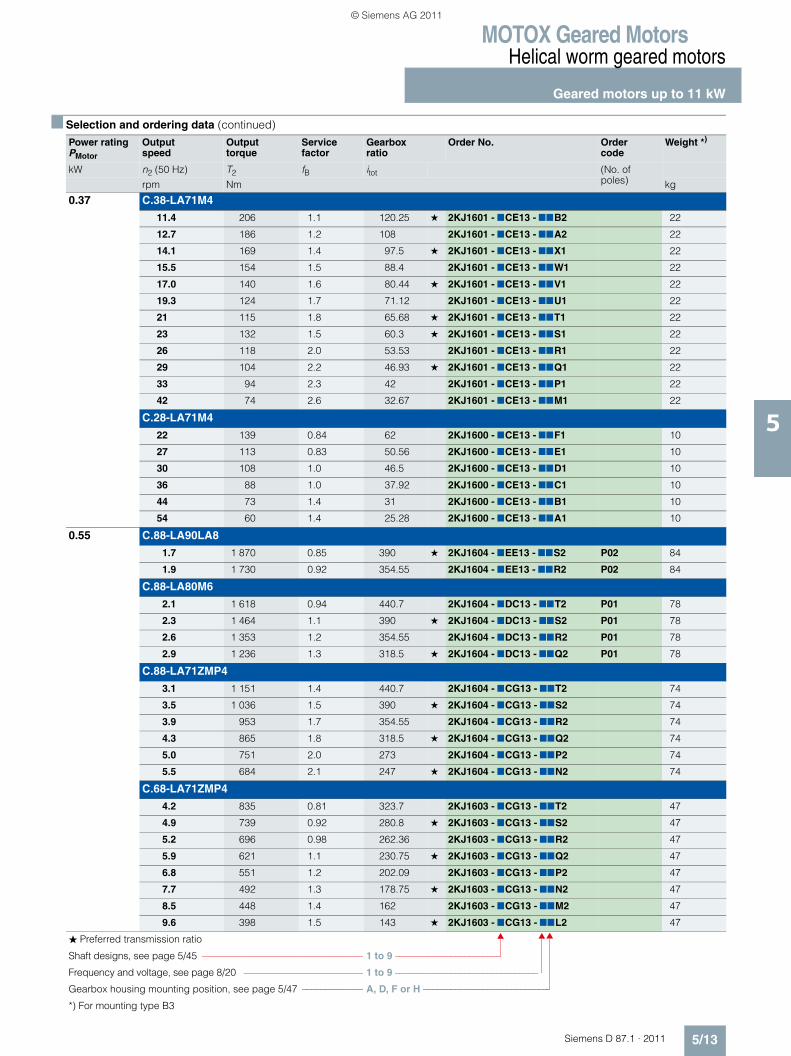
MOTOX Geared MotorsHelical worm geared motors
Geared motors up to 11 kW
5/13Siemens D 87.1 · 2011
5
0.37 C.38-LA71M4
11.4 206 1.1 120.25 ★ 2KJ1601 - 7CE13 - 77B2 22
12.7 186 1.2 108 2KJ1601 - 7CE13 - 77A2 22
14.1 169 1.4 97.5 ★ 2KJ1601 - 7CE13 - 77X1 22
15.5 154 1.5 88.4 2KJ1601 - 7CE13 - 77W1 22
17.0 140 1.6 80.44 ★ 2KJ1601 - 7CE13 - 77V1 22
19.3 124 1.7 71.12 2KJ1601 - 7CE13 - 77U1 22
21 115 1.8 65.68 ★ 2KJ1601 - 7CE13 - 77T1 22
23 132 1.5 60.3 ★ 2KJ1601 - 7CE13 - 77S1 22
26 118 2.0 53.53 2KJ1601 - 7CE13 - 77R1 22
29 104 2.2 46.93 ★ 2KJ1601 - 7CE13 - 77Q1 22
33 94 2.3 42 2KJ1601 - 7CE13 - 77P1 22
42 74 2.6 32.67 2KJ1601 - 7CE13 - 77M1 22
C.28-LA71M4
22 139 0.84 62 2KJ1600 - 7CE13 - 77F1 10
27 113 0.83 50.56 2KJ1600 - 7CE13 - 77E1 10
30 108 1.0 46.5 2KJ1600 - 7CE13 - 77D1 10
36 88 1.0 37.92 2KJ1600 - 7CE13 - 77C1 10
44 73 1.4 31 2KJ1600 - 7CE13 - 77B1 10
54 60 1.4 25.28 2KJ1600 - 7CE13 - 77A1 10
0.55 C.88-LA90LA8
1.7 1 870 0.85 390 ★ 2KJ1604 - 7EE13 - 77S2 P02 84
1.9 1 730 0.92 354.55 2KJ1604 - 7EE13 - 77R2 P02 84
C.88-LA80M6
2.1 1 618 0.94 440.7 2KJ1604 - 7DC13 - 77T2 P01 78
2.3 1 464 1.1 390 ★ 2KJ1604 - 7DC13 - 77S2 P01 78
2.6 1 353 1.2 354.55 2KJ1604 - 7DC13 - 77R2 P01 78
2.9 1 236 1.3 318.5 ★ 2KJ1604 - 7DC13 - 77Q2 P01 78
C.88-LA71ZMP4
3.1 1 151 1.4 440.7 2KJ1604 - 7CG13 - 77T2 74
3.5 1 036 1.5 390 ★ 2KJ1604 - 7CG13 - 77S2 74
3.9 953 1.7 354.55 2KJ1604 - 7CG13 - 77R2 74
4.3 865 1.8 318.5 ★ 2KJ1604 - 7CG13 - 77Q2 74
5.0 751 2.0 273 2KJ1604 - 7CG13 - 77P2 74
5.5 684 2.1 247 ★ 2KJ1604 - 7CG13 - 77N2 74
C.68-LA71ZMP4
4.2 835 0.81 323.7 2KJ1603 - 7CG13 - 77T2 47
4.9 739 0.92 280.8 ★ 2KJ1603 - 7CG13 - 77S2 47
5.2 696 0.98 262.36 2KJ1603 - 7CG13 - 77R2 47
5.9 621 1.1 230.75 ★ 2KJ1603 - 7CG13 - 77Q2 47
6.8 551 1.2 202.09 2KJ1603 - 7CG13 - 77P2 47
7.7 492 1.3 178.75 ★ 2KJ1603 - 7CG13 - 77N2 47
8.5 448 1.4 162 2KJ1603 - 7CG13 - 77M2 47
9.6 398 1.5 143 ★ 2KJ1603 - 7CG13 - 77L2 47
■ Selection and ordering data (continued)
Power ratingPMotor
Output speed
Output torque
Service factor
Gearbox ratio
Order No. Order code
Weight *)
kW n2 (50 Hz) T2 fB itot (No. of poles)rpm Nm kg
� Preferred transmission ratio
Shaft designs, see page 5/45 ––––––––––––––––––––––––––––––––– 1 to 9 ––––––––––––––––––––––
Frequency and voltage, see page 8/20 ––––––––––––––––––––––––– 1 to 9 –––––––––––––––––––––––––––––––
Gearbox housing mounting position, see page 5/47 ––––––––––––– A, D, F or H –––––––––––––––––––––––––––
*) For mounting type B3
© Siemens AG 2011
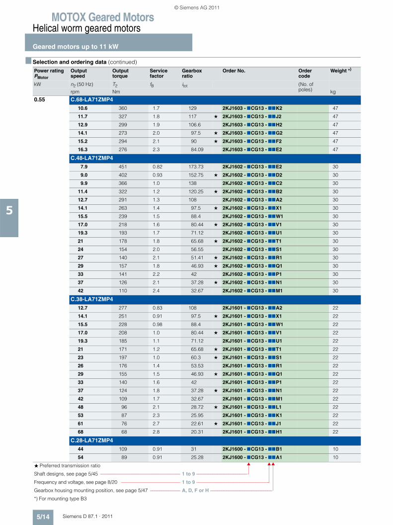
MOTOX Geared MotorsHelical worm geared motors
Geared motors up to 11 kW
5/14 Siemens D 87.1 · 2011
5
0.55 C.68-LA71ZMP4
10.6 360 1.7 129 2KJ1603 - 7CG13 - 77K2 47
11.7 327 1.8 117 ★ 2KJ1603 - 7CG13 - 77J2 47
12.9 299 1.9 106.6 2KJ1603 - 7CG13 - 77H2 47
14.1 273 2.0 97.5 ★ 2KJ1603 - 7CG13 - 77G2 47
15.2 294 2.1 90 ★ 2KJ1603 - 7CG13 - 77F2 47
16.3 276 2.3 84.09 2KJ1603 - 7CG13 - 77E2 47
C.48-LA71ZMP4
7.9 451 0.82 173.73 2KJ1602 - 7CG13 - 77E2 30
9.0 402 0.93 152.75 ★ 2KJ1602 - 7CG13 - 77D2 30
9.9 366 1.0 138 2KJ1602 - 7CG13 - 77C2 30
11.4 322 1.2 120.25 ★ 2KJ1602 - 7CG13 - 77B2 30
12.7 291 1.3 108 2KJ1602 - 7CG13 - 77A2 30
14.1 263 1.4 97.5 ★ 2KJ1602 - 7CG13 - 77X1 30
15.5 239 1.5 88.4 2KJ1602 - 7CG13 - 77W1 30
17.0 218 1.6 80.44 ★ 2KJ1602 - 7CG13 - 77V1 30
19.3 193 1.7 71.12 2KJ1602 - 7CG13 - 77U1 30
21 178 1.8 65.68 ★ 2KJ1602 - 7CG13 - 77T1 30
24 154 2.0 56.55 2KJ1602 - 7CG13 - 77S1 30
27 140 2.1 51.41 ★ 2KJ1602 - 7CG13 - 77R1 30
29 157 1.8 46.93 ★ 2KJ1602 - 7CG13 - 77Q1 30
33 141 2.2 42 2KJ1602 - 7CG13 - 77P1 30
37 126 2.1 37.28 ★ 2KJ1602 - 7CG13 - 77N1 30
42 110 2.4 32.67 2KJ1602 - 7CG13 - 77M1 30
C.38-LA71ZMP4
12.7 277 0.83 108 2KJ1601 - 7CG13 - 77A2 22
14.1 251 0.91 97.5 ★ 2KJ1601 - 7CG13 - 77X1 22
15.5 228 0.98 88.4 2KJ1601 - 7CG13 - 77W1 22
17.0 208 1.0 80.44 ★ 2KJ1601 - 7CG13 - 77V1 22
19.3 185 1.1 71.12 2KJ1601 - 7CG13 - 77U1 22
21 171 1.2 65.68 ★ 2KJ1601 - 7CG13 - 77T1 22
23 197 1.0 60.3 ★ 2KJ1601 - 7CG13 - 77S1 22
26 176 1.4 53.53 2KJ1601 - 7CG13 - 77R1 22
29 155 1.5 46.93 ★ 2KJ1601 - 7CG13 - 77Q1 22
33 140 1.6 42 2KJ1601 - 7CG13 - 77P1 22
37 124 1.8 37.28 ★ 2KJ1601 - 7CG13 - 77N1 22
42 109 1.7 32.67 2KJ1601 - 7CG13 - 77M1 22
48 96 2.1 28.72 ★ 2KJ1601 - 7CG13 - 77L1 22
53 87 2.3 25.95 2KJ1601 - 7CG13 - 77K1 22
61 76 2.7 22.61 ★ 2KJ1601 - 7CG13 - 77J1 22
68 68 2.8 20.31 2KJ1601 - 7CG13 - 77H1 22
C.28-LA71ZMP4
44 109 0.91 31 2KJ1600 - 7CG13 - 77B1 10
54 89 0.91 25.28 2KJ1600 - 7CG13 - 77A1 10
■ Selection and ordering data (continued)
Power ratingPMotor
Output speed
Output torque
Service factor
Gearbox ratio
Order No. Order code
Weight *)
kW n2 (50 Hz) T2 fB itot (No. of poles)rpm Nm kg
� Preferred transmission ratio
Shaft designs, see page 5/45 ––––––––––––––––––––––––––––––––– 1 to 9 ––––––––––––––––––––––
Frequency and voltage, see page 8/20 ––––––––––––––––––––––––– 1 to 9 –––––––––––––––––––––––––––––––
Gearbox housing mounting position, see page 5/47 ––––––––––––– A, D, F or H –––––––––––––––––––––––––––
*) For mounting type B3
© Siemens AG 2011
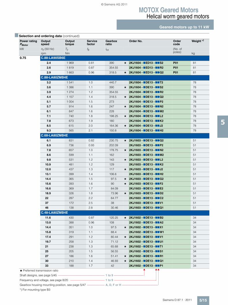
MOTOX Geared MotorsHelical worm geared motors
Geared motors up to 11 kW
5/15Siemens D 87.1 · 2011
5
0.75 C.88-LA90SB6E
2.4 1 969 0.81 390 ★ 2KJ1604 - 7ED13 - 77S2 P01 81
2.6 1 819 0.87 354.55 2KJ1604 - 7ED13 - 77R2 P01 81
2.9 1 663 0.96 318.5 ★ 2KJ1604 - 7ED13 - 77Q2 P01 81
C.88-LA80ZMB4E
3.2 1 541 1.0 440.7 2KJ1604 - 7DE13 - 77T2 78
3.6 1 386 1.1 390 ★ 2KJ1604 - 7DE13 - 77S2 78
3.9 1 274 1.2 354.55 2KJ1604 - 7DE13 - 77R2 78
4.4 1 157 1.4 318.5 ★ 2KJ1604 - 7DE13 - 77Q2 78
5.1 1 004 1.5 273 2KJ1604 - 7DE13 - 77P2 78
5.7 914 1.6 247 ★ 2KJ1604 - 7DE13 - 77N2 78
6.1 847 1.6 228 2KJ1604 - 7DE13 - 77M2 78
7.1 740 1.8 198.25 ★ 2KJ1604 - 7DE13 - 77L2 78
7.8 673 1.9 180 2KJ1604 - 7DE13 - 77K2 78
8.5 615 2.0 164.36 ★ 2KJ1604 - 7DE13 - 77J2 78
9.3 565 2.1 150.8 2KJ1604 - 7DE13 - 77H2 78
C.68-LA80ZMB4E
6.1 831 0.82 230.75 ★ 2KJ1603 - 7DE13 - 77Q2 51
6.9 736 0.93 202.09 2KJ1603 - 7DE13 - 77P2 51
7.8 657 1.0 178.75 ★ 2KJ1603 - 7DE13 - 77N2 51
8.6 599 1.1 162 2KJ1603 - 7DE13 - 77M2 51
9.8 531 1.2 143 ★ 2KJ1603 - 7DE13 - 77L2 51
10.9 481 1.2 129 2KJ1603 - 7DE13 - 77K2 51
12.0 437 1.3 117 ★ 2KJ1603 - 7DE13 - 77J2 51
13.1 399 1.4 106.6 2KJ1603 - 7DE13 - 77H2 51
14.4 365 1.5 97.5 ★ 2KJ1603 - 7DE13 - 77G2 51
15.6 393 1.6 90 ★ 2KJ1603 - 7DE13 - 77F2 51
16.6 369 1.7 84.09 2KJ1603 - 7DE13 - 77E2 51
18.9 326 1.8 73.96 ★ 2KJ1603 - 7DE13 - 77D2 51
22 287 2.2 64.77 2KJ1603 - 7DE13 - 77C2 51
37 172 2.5 38 2KJ1603 - 7DE13 - 77V1 51
46 138 2.8 30.46 2KJ1603 - 7DE13 - 77Q1 51
C.48-LA80ZMB4E
11.6 430 0.87 120.25 ★ 2KJ1602 - 7DE13 - 77B2 34
13.0 388 0.96 108 2KJ1602 - 7DE13 - 77A2 34
14.4 351 1.0 97.5 ★ 2KJ1602 - 7DE13 - 77X1 34
15.8 319 1.1 88.4 2KJ1602 - 7DE13 - 77W1 34
17.4 291 1.2 80.44 ★ 2KJ1602 - 7DE13 - 77V1 34
19.7 258 1.3 71.12 2KJ1602 - 7DE13 - 77U1 34
21 238 1.3 65.68 ★ 2KJ1602 - 7DE13 - 77T1 34
25 205 1.5 56.55 2KJ1602 - 7DE13 - 77S1 34
27 186 1.6 51.41 ★ 2KJ1602 - 7DE13 - 77R1 34
30 210 1.4 46.93 ★ 2KJ1602 - 7DE13 - 77Q1 34
33 188 1.7 42 2KJ1602 - 7DE13 - 77P1 34
■ Selection and ordering data (continued)
Power ratingPMotor
Output speed
Output torque
Service factor
Gearbox ratio
Order No. Order code
Weight *)
kW n2 (50 Hz) T2 fB itot (No. of poles)rpm Nm kg
� Preferred transmission ratio
Shaft designs, see page 5/45 ––––––––––––––––––––––––––––––––– 1 to 9 ––––––––––––––––––––––
Frequency and voltage, see page 8/20 ––––––––––––––––––––––––– 1 to 9 –––––––––––––––––––––––––––––––
Gearbox housing mounting position, see page 5/47 ––––––––––––– A, D, F or H –––––––––––––––––––––––––––
*) For mounting type B3
© Siemens AG 2011
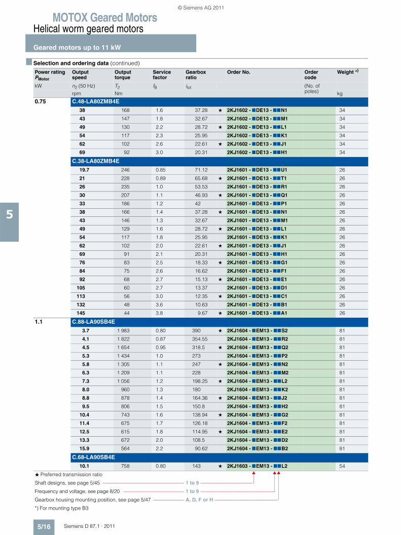
MOTOX Geared MotorsHelical worm geared motors
Geared motors up to 11 kW
5/16 Siemens D 87.1 · 2011
5
0.75 C.48-LA80ZMB4E
38 168 1.6 37.28 ★ 2KJ1602 - 7DE13 - 77N1 34
43 147 1.8 32.67 2KJ1602 - 7DE13 - 77M1 34
49 130 2.2 28.72 ★ 2KJ1602 - 7DE13 - 77L1 34
54 117 2.3 25.95 2KJ1602 - 7DE13 - 77K1 34
62 102 2.6 22.61 ★ 2KJ1602 - 7DE13 - 77J1 34
69 92 3.0 20.31 2KJ1602 - 7DE13 - 77H1 34
C.38-LA80ZMB4E
19.7 246 0.85 71.12 2KJ1601 - 7DE13 - 77U1 26
21 228 0.89 65.68 ★ 2KJ1601 - 7DE13 - 77T1 26
26 235 1.0 53.53 2KJ1601 - 7DE13 - 77R1 26
30 207 1.1 46.93 ★ 2KJ1601 - 7DE13 - 77Q1 26
33 186 1.2 42 2KJ1601 - 7DE13 - 77P1 26
38 166 1.4 37.28 ★ 2KJ1601 - 7DE13 - 77N1 26
43 146 1.3 32.67 2KJ1601 - 7DE13 - 77M1 26
49 129 1.6 28.72 ★ 2KJ1601 - 7DE13 - 77L1 26
54 117 1.8 25.95 2KJ1601 - 7DE13 - 77K1 26
62 102 2.0 22.61 ★ 2KJ1601 - 7DE13 - 77J1 26
69 91 2.1 20.31 2KJ1601 - 7DE13 - 77H1 26
76 83 2.5 18.33 ★ 2KJ1601 - 7DE13 - 77G1 26
84 75 2.6 16.62 2KJ1601 - 7DE13 - 77F1 26
92 68 2.7 15.13 ★ 2KJ1601 - 7DE13 - 77E1 26
105 60 2.7 13.37 2KJ1601 - 7DE13 - 77D1 26
113 56 3.0 12.35 ★ 2KJ1601 - 7DE13 - 77C1 26
132 48 3.6 10.63 2KJ1601 - 7DE13 - 77B1 26
145 44 3.8 9.67 ★ 2KJ1601 - 7DE13 - 77A1 26
1.1 C.88-LA90SB4E
3.7 1 983 0.80 390 ★ 2KJ1604 - 7EM13 - 77S2 81
4.1 1 822 0.87 354.55 2KJ1604 - 7EM13 - 77R2 81
4.5 1 654 0.95 318.5 ★ 2KJ1604 - 7EM13 - 77Q2 81
5.3 1 434 1.0 273 2KJ1604 - 7EM13 - 77P2 81
5.8 1 305 1.1 247 ★ 2KJ1604 - 7EM13 - 77N2 81
6.3 1 209 1.1 228 2KJ1604 - 7EM13 - 77M2 81
7.3 1 056 1.2 198.25 ★ 2KJ1604 - 7EM13 - 77L2 81
8.0 960 1.3 180 2KJ1604 - 7EM13 - 77K2 81
8.8 878 1.4 164.36 ★ 2KJ1604 - 7EM13 - 77J2 81
9.5 806 1.5 150.8 2KJ1604 - 7EM13 - 77H2 81
10.4 743 1.6 138.94 ★ 2KJ1604 - 7EM13 - 77G2 81
11.4 675 1.7 126.18 2KJ1604 - 7EM13 - 77F2 81
12.5 615 1.8 114.95 ★ 2KJ1604 - 7EM13 - 77E2 81
13.3 672 2.0 108.5 2KJ1604 - 7EM13 - 77D2 81
15.9 564 2.2 90.62 2KJ1604 - 7EM13 - 77B2 81
C.68-LA90SB4E
10.1 758 0.80 143 ★ 2KJ1603 - 7EM13 - 77L2 54
■ Selection and ordering data (continued)
Power ratingPMotor
Output speed
Output torque
Service factor
Gearbox ratio
Order No. Order code
Weight *)
kW n2 (50 Hz) T2 fB itot (No. of poles)rpm Nm kg
� Preferred transmission ratio
Shaft designs, see page 5/45 ––––––––––––––––––––––––––––––––– 1 to 9 ––––––––––––––––––––––
Frequency and voltage, see page 8/20 ––––––––––––––––––––––––– 1 to 9 –––––––––––––––––––––––––––––––
Gearbox housing mounting position, see page 5/47 ––––––––––––– A, D, F or H –––––––––––––––––––––––––––
*) For mounting type B3
© Siemens AG 2011
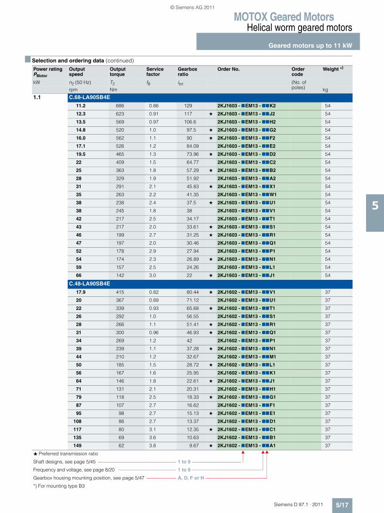
MOTOX Geared MotorsHelical worm geared motors
Geared motors up to 11 kW
5/17Siemens D 87.1 · 2011
5
1.1 C.68-LA90SB4E
11.2 686 0.86 129 2KJ1603 - 7EM13 - 77K2 54
12.3 623 0.91 117 ★ 2KJ1603 - 7EM13 - 77J2 54
13.5 569 0.97 106.6 2KJ1603 - 7EM13 - 77H2 54
14.8 520 1.0 97.5 ★ 2KJ1603 - 7EM13 - 77G2 54
16.0 562 1.1 90 ★ 2KJ1603 - 7EM13 - 77F2 54
17.1 526 1.2 84.09 2KJ1603 - 7EM13 - 77E2 54
19.5 465 1.3 73.96 ★ 2KJ1603 - 7EM13 - 77D2 54
22 409 1.5 64.77 2KJ1603 - 7EM13 - 77C2 54
25 363 1.8 57.29 ★ 2KJ1603 - 7EM13 - 77B2 54
28 329 1.9 51.92 2KJ1603 - 7EM13 - 77A2 54
31 291 2.1 45.83 ★ 2KJ1603 - 7EM13 - 77X1 54
35 263 2.2 41.35 2KJ1603 - 7EM13 - 77W1 54
38 238 2.4 37.5 ★ 2KJ1603 - 7EM13 - 77U1 54
38 245 1.8 38 2KJ1603 - 7EM13 - 77V1 54
42 217 2.5 34.17 2KJ1603 - 7EM13 - 77T1 54
43 217 2.0 33.61 ★ 2KJ1603 - 7EM13 - 77S1 54
46 199 2.7 31.25 ★ 2KJ1603 - 7EM13 - 77R1 54
47 197 2.0 30.46 2KJ1603 - 7EM13 - 77Q1 54
52 178 2.9 27.94 2KJ1603 - 7EM13 - 77P1 54
54 174 2.3 26.89 ★ 2KJ1603 - 7EM13 - 77N1 54
59 157 2.5 24.26 2KJ1603 - 7EM13 - 77L1 54
66 142 3.0 22 ★ 2KJ1603 - 7EM13 - 77J1 54
C.48-LA90SB4E
17.9 415 0.82 80.44 ★ 2KJ1602 - 7EM13 - 77V1 37
20 367 0.89 71.12 2KJ1602 - 7EM13 - 77U1 37
22 339 0.93 65.68 ★ 2KJ1602 - 7EM13 - 77T1 37
26 292 1.0 56.55 2KJ1602 - 7EM13 - 77S1 37
28 266 1.1 51.41 ★ 2KJ1602 - 7EM13 - 77R1 37
31 300 0.96 46.93 ★ 2KJ1602 - 7EM13 - 77Q1 37
34 269 1.2 42 2KJ1602 - 7EM13 - 77P1 37
39 239 1.1 37.28 ★ 2KJ1602 - 7EM13 - 77N1 37
44 210 1.2 32.67 2KJ1602 - 7EM13 - 77M1 37
50 185 1.5 28.72 ★ 2KJ1602 - 7EM13 - 77L1 37
56 167 1.6 25.95 2KJ1602 - 7EM13 - 77K1 37
64 146 1.8 22.61 ★ 2KJ1602 - 7EM13 - 77J1 37
71 131 2.1 20.31 2KJ1602 - 7EM13 - 77H1 37
79 118 2.5 18.33 ★ 2KJ1602 - 7EM13 - 77G1 37
87 107 2.7 16.62 2KJ1602 - 7EM13 - 77F1 37
95 98 2.7 15.13 ★ 2KJ1602 - 7EM13 - 77E1 37
108 86 2.7 13.37 2KJ1602 - 7EM13 - 77D1 37
117 80 3.1 12.35 ★ 2KJ1602 - 7EM13 - 77C1 37
135 69 3.6 10.63 2KJ1602 - 7EM13 - 77B1 37
149 62 3.8 9.67 ★ 2KJ1602 - 7EM13 - 77A1 37
■ Selection and ordering data (continued)
Power ratingPMotor
Output speed
Output torque
Service factor
Gearbox ratio
Order No. Order code
Weight *)
kW n2 (50 Hz) T2 fB itot (No. of poles)rpm Nm kg
� Preferred transmission ratio
Shaft designs, see page 5/45 ––––––––––––––––––––––––––––––––– 1 to 9 ––––––––––––––––––––––
Frequency and voltage, see page 8/20 ––––––––––––––––––––––––– 1 to 9 –––––––––––––––––––––––––––––––
Gearbox housing mounting position, see page 5/47 ––––––––––––– A, D, F or H –––––––––––––––––––––––––––
*) For mounting type B3
© Siemens AG 2011
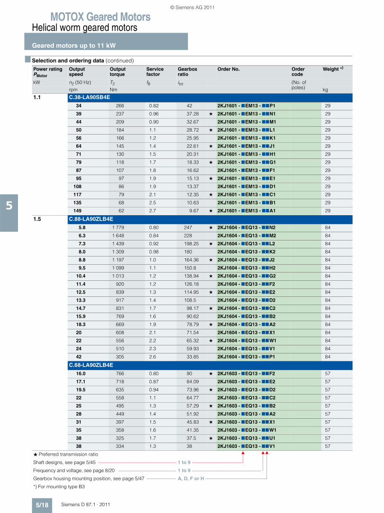
MOTOX Geared MotorsHelical worm geared motors
Geared motors up to 11 kW
5/18 Siemens D 87.1 · 2011
5
1.1 C.38-LA90SB4E
34 266 0.82 42 2KJ1601 - 7EM13 - 77P1 29
39 237 0.96 37.28 ★ 2KJ1601 - 7EM13 - 77N1 29
44 209 0.90 32.67 2KJ1601 - 7EM13 - 77M1 29
50 184 1.1 28.72 ★ 2KJ1601 - 7EM13 - 77L1 29
56 166 1.2 25.95 2KJ1601 - 7EM13 - 77K1 29
64 145 1.4 22.61 ★ 2KJ1601 - 7EM13 - 77J1 29
71 130 1.5 20.31 2KJ1601 - 7EM13 - 77H1 29
79 118 1.7 18.33 ★ 2KJ1601 - 7EM13 - 77G1 29
87 107 1.8 16.62 2KJ1601 - 7EM13 - 77F1 29
95 97 1.9 15.13 ★ 2KJ1601 - 7EM13 - 77E1 29
108 86 1.9 13.37 2KJ1601 - 7EM13 - 77D1 29
117 79 2.1 12.35 ★ 2KJ1601 - 7EM13 - 77C1 29
135 68 2.5 10.63 2KJ1601 - 7EM13 - 77B1 29
149 62 2.7 9.67 ★ 2KJ1601 - 7EM13 - 77A1 29
1.5 C.88-LA90ZLB4E
5.8 1 779 0.80 247 ★ 2KJ1604 - 7EQ13 - 77N2 84
6.3 1 648 0.84 228 2KJ1604 - 7EQ13 - 77M2 84
7.3 1 439 0.92 198.25 ★ 2KJ1604 - 7EQ13 - 77L2 84
8.0 1 309 0.98 180 2KJ1604 - 7EQ13 - 77K2 84
8.8 1 197 1.0 164.36 ★ 2KJ1604 - 7EQ13 - 77J2 84
9.5 1 099 1.1 150.8 2KJ1604 - 7EQ13 - 77H2 84
10.4 1 013 1.2 138.94 ★ 2KJ1604 - 7EQ13 - 77G2 84
11.4 920 1.2 126.18 2KJ1604 - 7EQ13 - 77F2 84
12.5 839 1.3 114.95 ★ 2KJ1604 - 7EQ13 - 77E2 84
13.3 917 1.4 108.5 2KJ1604 - 7EQ13 - 77D2 84
14.7 831 1.7 98.17 ★ 2KJ1604 - 7EQ13 - 77C2 84
15.9 769 1.6 90.62 2KJ1604 - 7EQ13 - 77B2 84
18.3 669 1.9 78.79 ★ 2KJ1604 - 7EQ13 - 77A2 84
20 608 2.1 71.54 2KJ1604 - 7EQ13 - 77X1 84
22 556 2.2 65.32 ★ 2KJ1604 - 7EQ13 - 77W1 84
24 510 2.3 59.93 2KJ1604 - 7EQ13 - 77V1 84
42 305 2.6 33.85 2KJ1604 - 7EQ13 - 77P1 84
C.68-LA90ZLB4E
16.0 766 0.80 90 ★ 2KJ1603 - 7EQ13 - 77F2 57
17.1 718 0.87 84.09 2KJ1603 - 7EQ13 - 77E2 57
19.5 635 0.94 73.96 ★ 2KJ1603 - 7EQ13 - 77D2 57
22 558 1.1 64.77 2KJ1603 - 7EQ13 - 77C2 57
25 495 1.3 57.29 ★ 2KJ1603 - 7EQ13 - 77B2 57
28 449 1.4 51.92 2KJ1603 - 7EQ13 - 77A2 57
31 397 1.5 45.83 ★ 2KJ1603 - 7EQ13 - 77X1 57
35 358 1.6 41.35 2KJ1603 - 7EQ13 - 77W1 57
38 325 1.7 37.5 ★ 2KJ1603 - 7EQ13 - 77U1 57
38 334 1.3 38 2KJ1603 - 7EQ13 - 77V1 57
■ Selection and ordering data (continued)
Power ratingPMotor
Output speed
Output torque
Service factor
Gearbox ratio
Order No. Order code
Weight *)
kW n2 (50 Hz) T2 fB itot (No. of poles)rpm Nm kg
� Preferred transmission ratio
Shaft designs, see page 5/45 ––––––––––––––––––––––––––––––––– 1 to 9 ––––––––––––––––––––––
Frequency and voltage, see page 8/20 ––––––––––––––––––––––––– 1 to 9 –––––––––––––––––––––––––––––––
Gearbox housing mounting position, see page 5/47 ––––––––––––– A, D, F or H –––––––––––––––––––––––––––
*) For mounting type B3
© Siemens AG 2011
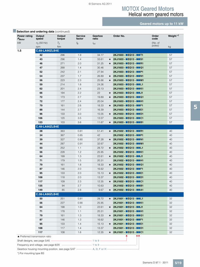
MOTOX Geared MotorsHelical worm geared motors
Geared motors up to 11 kW
5/19Siemens D 87.1 · 2011
5
1.5 C.68-LA90ZLB4E
42 296 1.9 34.17 2KJ1603 - 7EQ13 - 77T1 57
43 296 1.4 33.61 ★ 2KJ1603 - 7EQ13 - 77S1 57
46 271 2.0 31.25 ★ 2KJ1603 - 7EQ13 - 77R1 57
47 268 1.4 30.46 2KJ1603 - 7EQ13 - 77Q1 57
52 242 2.1 27.94 2KJ1603 - 7EQ13 - 77P1 57
54 237 1.7 26.89 ★ 2KJ1603 - 7EQ13 - 77N1 57
56 223 2.3 25.66 ★ 2KJ1603 - 7EQ13 - 77M1 57
59 214 1.8 24.26 2KJ1603 - 7EQ13 - 77L1 57
62 201 2.4 23.13 2KJ1603 - 7EQ13 - 77K1 57
66 194 2.2 22 ★ 2KJ1603 - 7EQ13 - 77J1 57
72 173 2.7 19.89 ★ 2KJ1603 - 7EQ13 - 77G1 57
72 177 2.4 20.04 2KJ1603 - 7EQ13 - 77H1 57
79 161 2.6 18.33 ★ 2KJ1603 - 7EQ13 - 77F1 57
88 144 2.7 16.39 2KJ1603 - 7EQ13 - 77E1 57
96 133 3.0 15.05 ★ 2KJ1603 - 7EQ13 - 77D1 57
106 120 3.5 13.57 2KJ1603 - 7EQ13 - 77C1 57
123 103 3.6 11.67 ★ 2KJ1603 - 7EQ13 - 77B1 57
C.48-LA90ZLB4E
28 363 0.81 51.41 ★ 2KJ1602 - 7EQ13 - 77R1 40
34 367 0.85 42 2KJ1602 - 7EQ13 - 77P1 40
39 327 0.80 37.28 ★ 2KJ1602 - 7EQ13 - 77N1 40
44 287 0.91 32.67 2KJ1602 - 7EQ13 - 77M1 40
50 252 1.1 28.72 ★ 2KJ1602 - 7EQ13 - 77L1 40
56 228 1.2 25.95 2KJ1602 - 7EQ13 - 77K1 40
64 199 1.3 22.61 ★ 2KJ1602 - 7EQ13 - 77J1 40
71 179 1.5 20.31 2KJ1602 - 7EQ13 - 77H1 40
79 161 1.8 18.33 ★ 2KJ1602 - 7EQ13 - 77G1 40
87 146 2.0 16.62 2KJ1602 - 7EQ13 - 77F1 40
95 133 2.0 15.13 ★ 2KJ1602 - 7EQ13 - 77E1 40
108 118 2.0 13.37 2KJ1602 - 7EQ13 - 77D1 40
117 109 2.3 12.35 ★ 2KJ1602 - 7EQ13 - 77C1 40
135 94 2.7 10.63 2KJ1602 - 7EQ13 - 77B1 40
149 85 2.8 9.67 ★ 2KJ1602 - 7EQ13 - 77A1 40
C.38-LA90ZLB4E
50 251 0.81 28.72 ★ 2KJ1601 - 7EQ13 - 77L1 32
56 227 0.90 25.95 2KJ1601 - 7EQ13 - 77K1 32
64 198 1.0 22.61 ★ 2KJ1601 - 7EQ13 - 77J1 32
71 178 1.1 20.31 2KJ1601 - 7EQ13 - 77H1 32
79 161 1.3 18.33 ★ 2KJ1601 - 7EQ13 - 77G1 32
87 146 1.3 16.62 2KJ1601 - 7EQ13 - 77F1 32
95 133 1.4 15.13 ★ 2KJ1601 - 7EQ13 - 77E1 32
108 117 1.4 13.37 2KJ1601 - 7EQ13 - 77D1 32
117 108 1.6 12.35 ★ 2KJ1601 - 7EQ13 - 77C1 32
■ Selection and ordering data (continued)
Power ratingPMotor
Output speed
Output torque
Service factor
Gearbox ratio
Order No. Order code
Weight *)
kW n2 (50 Hz) T2 fB itot (No. of poles)rpm Nm kg
� Preferred transmission ratio
Shaft designs, see page 5/45 ––––––––––––––––––––––––––––––––– 1 to 9 ––––––––––––––––––––––
Frequency and voltage, see page 8/20 ––––––––––––––––––––––––– 1 to 9 –––––––––––––––––––––––––––––––
Gearbox housing mounting position, see page 5/47 ––––––––––––– A, D, F or H –––––––––––––––––––––––––––
*) For mounting type B3
© Siemens AG 2011
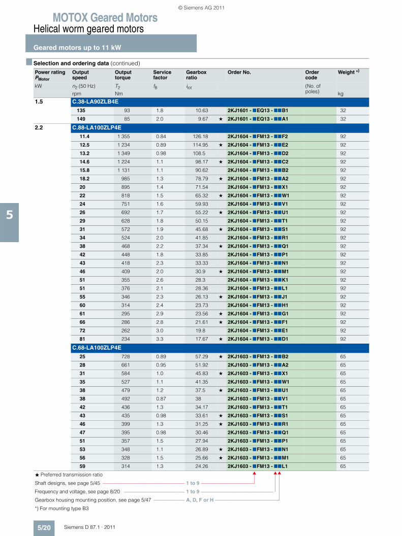
MOTOX Geared MotorsHelical worm geared motors
Geared motors up to 11 kW
5/20 Siemens D 87.1 · 2011
5
1.5 C.38-LA90ZLB4E
135 93 1.8 10.63 2KJ1601 - 7EQ13 - 77B1 32
149 85 2.0 9.67 ★ 2KJ1601 - 7EQ13 - 77A1 32
2.2 C.88-LA100ZLP4E
11.4 1 355 0.84 126.18 2KJ1604 - 7FM13 - 77F2 92
12.5 1 234 0.89 114.95 ★ 2KJ1604 - 7FM13 - 77E2 92
13.2 1 349 0.98 108.5 2KJ1604 - 7FM13 - 77D2 92
14.6 1 224 1.1 98.17 ★ 2KJ1604 - 7FM13 - 77C2 92
15.8 1 131 1.1 90.62 2KJ1604 - 7FM13 - 77B2 92
18.2 985 1.3 78.79 ★ 2KJ1604 - 7FM13 - 77A2 92
20 895 1.4 71.54 2KJ1604 - 7FM13 - 77X1 92
22 818 1.5 65.32 ★ 2KJ1604 - 7FM13 - 77W1 92
24 751 1.6 59.93 2KJ1604 - 7FM13 - 77V1 92
26 692 1.7 55.22 ★ 2KJ1604 - 7FM13 - 77U1 92
29 628 1.8 50.15 2KJ1604 - 7FM13 - 77T1 92
31 572 1.9 45.68 ★ 2KJ1604 - 7FM13 - 77S1 92
34 524 2.0 41.85 2KJ1604 - 7FM13 - 77R1 92
38 468 2.2 37.34 ★ 2KJ1604 - 7FM13 - 77Q1 92
42 448 1.8 33.85 2KJ1604 - 7FM13 - 77P1 92
43 418 2.3 33.33 2KJ1604 - 7FM13 - 77N1 92
46 409 2.0 30.9 ★ 2KJ1604 - 7FM13 - 77M1 92
51 355 2.6 28.3 2KJ1604 - 7FM13 - 77K1 92
51 376 2.1 28.36 2KJ1604 - 7FM13 - 77L1 92
55 346 2.3 26.13 ★ 2KJ1604 - 7FM13 - 77J1 92
60 314 2.4 23.73 2KJ1604 - 7FM13 - 77H1 92
61 295 2.9 23.56 ★ 2KJ1604 - 7FM13 - 77G1 92
66 286 2.8 21.61 ★ 2KJ1604 - 7FM13 - 77F1 92
72 262 3.0 19.8 2KJ1604 - 7FM13 - 77E1 92
81 234 3.3 17.67 ★ 2KJ1604 - 7FM13 - 77D1 92
C.68-LA100ZLP4E
25 728 0.89 57.29 ★ 2KJ1603 - 7FM13 - 77B2 65
28 661 0.95 51.92 2KJ1603 - 7FM13 - 77A2 65
31 584 1.0 45.83 ★ 2KJ1603 - 7FM13 - 77X1 65
35 527 1.1 41.35 2KJ1603 - 7FM13 - 77W1 65
38 479 1.2 37.5 ★ 2KJ1603 - 7FM13 - 77U1 65
38 492 0.87 38 2KJ1603 - 7FM13 - 77V1 65
42 436 1.3 34.17 2KJ1603 - 7FM13 - 77T1 65
43 435 0.98 33.61 ★ 2KJ1603 - 7FM13 - 77S1 65
46 399 1.3 31.25 ★ 2KJ1603 - 7FM13 - 77R1 65
47 395 0.98 30.46 2KJ1603 - 7FM13 - 77Q1 65
51 357 1.5 27.94 2KJ1603 - 7FM13 - 77P1 65
53 348 1.1 26.89 ★ 2KJ1603 - 7FM13 - 77N1 65
56 328 1.5 25.66 ★ 2KJ1603 - 7FM13 - 77M1 65
59 314 1.3 24.26 2KJ1603 - 7FM13 - 77L1 65
■ Selection and ordering data (continued)
Power ratingPMotor
Output speed
Output torque
Service factor
Gearbox ratio
Order No. Order code
Weight *)
kW n2 (50 Hz) T2 fB itot (No. of poles)rpm Nm kg
� Preferred transmission ratio
Shaft designs, see page 5/45 ––––––––––––––––––––––––––––––––– 1 to 9 ––––––––––––––––––––––
Frequency and voltage, see page 8/20 ––––––––––––––––––––––––– 1 to 9 –––––––––––––––––––––––––––––––
Gearbox housing mounting position, see page 5/47 ––––––––––––– A, D, F or H –––––––––––––––––––––––––––
*) For mounting type B3
© Siemens AG 2011
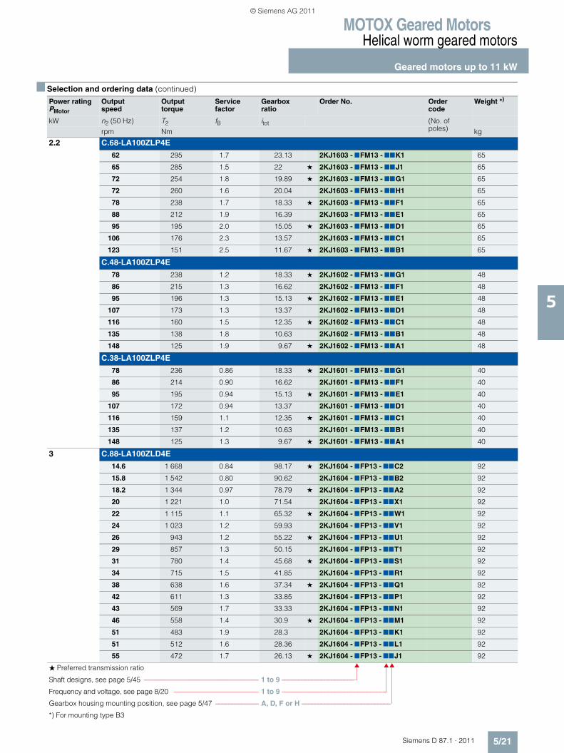
MOTOX Geared MotorsHelical worm geared motors
Geared motors up to 11 kW
5/21Siemens D 87.1 · 2011
5
2.2 C.68-LA100ZLP4E
62 295 1.7 23.13 2KJ1603 - 7FM13 - 77K1 65
65 285 1.5 22 ★ 2KJ1603 - 7FM13 - 77J1 65
72 254 1.8 19.89 ★ 2KJ1603 - 7FM13 - 77G1 65
72 260 1.6 20.04 2KJ1603 - 7FM13 - 77H1 65
78 238 1.7 18.33 ★ 2KJ1603 - 7FM13 - 77F1 65
88 212 1.9 16.39 2KJ1603 - 7FM13 - 77E1 65
95 195 2.0 15.05 ★ 2KJ1603 - 7FM13 - 77D1 65
106 176 2.3 13.57 2KJ1603 - 7FM13 - 77C1 65
123 151 2.5 11.67 ★ 2KJ1603 - 7FM13 - 77B1 65
C.48-LA100ZLP4E
78 238 1.2 18.33 ★ 2KJ1602 - 7FM13 - 77G1 48
86 215 1.3 16.62 2KJ1602 - 7FM13 - 77F1 48
95 196 1.3 15.13 ★ 2KJ1602 - 7FM13 - 77E1 48
107 173 1.3 13.37 2KJ1602 - 7FM13 - 77D1 48
116 160 1.5 12.35 ★ 2KJ1602 - 7FM13 - 77C1 48
135 138 1.8 10.63 2KJ1602 - 7FM13 - 77B1 48
148 125 1.9 9.67 ★ 2KJ1602 - 7FM13 - 77A1 48
C.38-LA100ZLP4E
78 236 0.86 18.33 ★ 2KJ1601 - 7FM13 - 77G1 40
86 214 0.90 16.62 2KJ1601 - 7FM13 - 77F1 40
95 195 0.94 15.13 ★ 2KJ1601 - 7FM13 - 77E1 40
107 172 0.94 13.37 2KJ1601 - 7FM13 - 77D1 40
116 159 1.1 12.35 ★ 2KJ1601 - 7FM13 - 77C1 40
135 137 1.2 10.63 2KJ1601 - 7FM13 - 77B1 40
148 125 1.3 9.67 ★ 2KJ1601 - 7FM13 - 77A1 40
3 C.88-LA100ZLD4E
14.6 1 668 0.84 98.17 ★ 2KJ1604 - 7FP13 - 77C2 92
15.8 1 542 0.80 90.62 2KJ1604 - 7FP13 - 77B2 92
18.2 1 344 0.97 78.79 ★ 2KJ1604 - 7FP13 - 77A2 92
20 1 221 1.0 71.54 2KJ1604 - 7FP13 - 77X1 92
22 1 115 1.1 65.32 ★ 2KJ1604 - 7FP13 - 77W1 92
24 1 023 1.2 59.93 2KJ1604 - 7FP13 - 77V1 92
26 943 1.2 55.22 ★ 2KJ1604 - 7FP13 - 77U1 92
29 857 1.3 50.15 2KJ1604 - 7FP13 - 77T1 92
31 780 1.4 45.68 ★ 2KJ1604 - 7FP13 - 77S1 92
34 715 1.5 41.85 2KJ1604 - 7FP13 - 77R1 92
38 638 1.6 37.34 ★ 2KJ1604 - 7FP13 - 77Q1 92
42 611 1.3 33.85 2KJ1604 - 7FP13 - 77P1 92
43 569 1.7 33.33 2KJ1604 - 7FP13 - 77N1 92
46 558 1.4 30.9 ★ 2KJ1604 - 7FP13 - 77M1 92
51 483 1.9 28.3 2KJ1604 - 7FP13 - 77K1 92
51 512 1.6 28.36 2KJ1604 - 7FP13 - 77L1 92
55 472 1.7 26.13 ★ 2KJ1604 - 7FP13 - 77J1 92
■ Selection and ordering data (continued)
Power ratingPMotor
Output speed
Output torque
Service factor
Gearbox ratio
Order No. Order code
Weight *)
kW n2 (50 Hz) T2 fB itot (No. of poles)rpm Nm kg
� Preferred transmission ratio
Shaft designs, see page 5/45 ––––––––––––––––––––––––––––––––– 1 to 9 ––––––––––––––––––––––
Frequency and voltage, see page 8/20 ––––––––––––––––––––––––– 1 to 9 –––––––––––––––––––––––––––––––
Gearbox housing mounting position, see page 5/47 ––––––––––––– A, D, F or H –––––––––––––––––––––––––––
*) For mounting type B3
© Siemens AG 2011
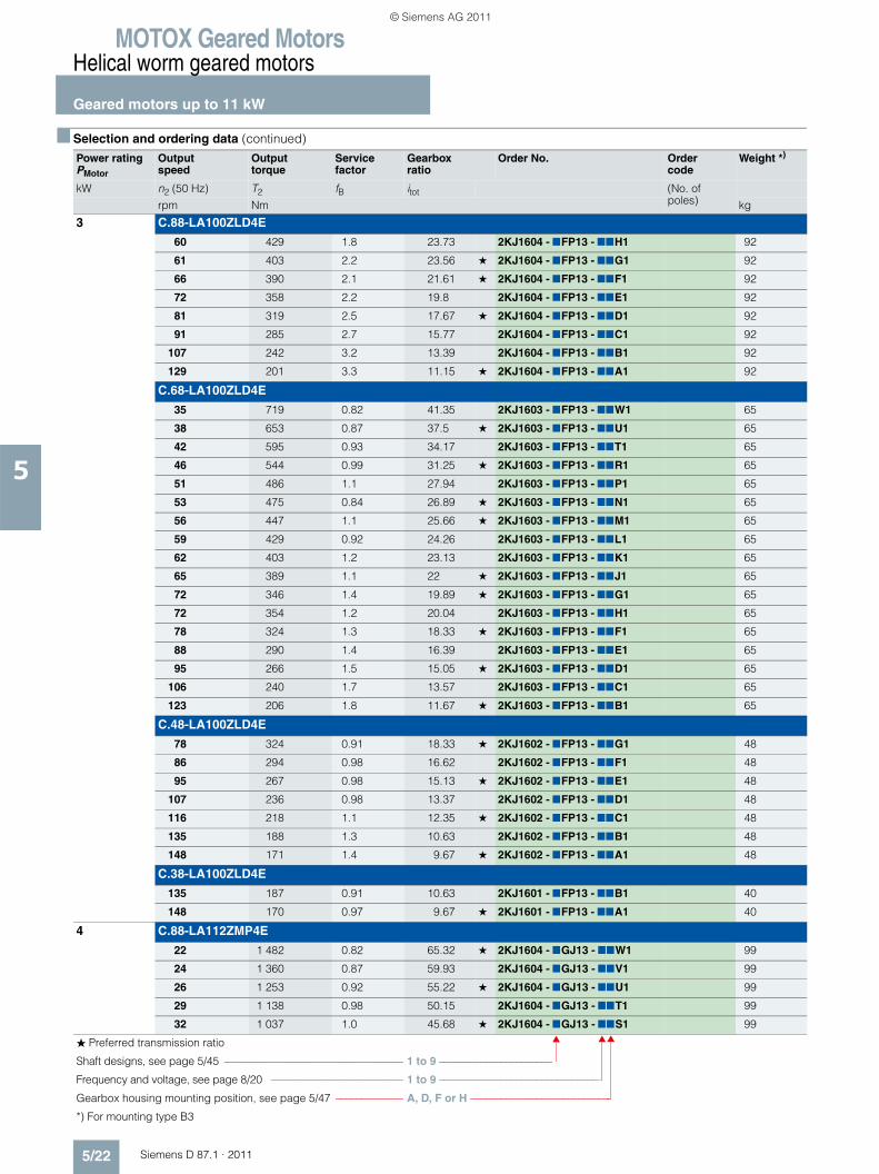
MOTOX Geared MotorsHelical worm geared motors
Geared motors up to 11 kW
5/22 Siemens D 87.1 · 2011
5
3 C.88-LA100ZLD4E
60 429 1.8 23.73 2KJ1604 - 7FP13 - 77H1 92
61 403 2.2 23.56 ★ 2KJ1604 - 7FP13 - 77G1 92
66 390 2.1 21.61 ★ 2KJ1604 - 7FP13 - 77F1 92
72 358 2.2 19.8 2KJ1604 - 7FP13 - 77E1 92
81 319 2.5 17.67 ★ 2KJ1604 - 7FP13 - 77D1 92
91 285 2.7 15.77 2KJ1604 - 7FP13 - 77C1 92
107 242 3.2 13.39 2KJ1604 - 7FP13 - 77B1 92
129 201 3.3 11.15 ★ 2KJ1604 - 7FP13 - 77A1 92
C.68-LA100ZLD4E
35 719 0.82 41.35 2KJ1603 - 7FP13 - 77W1 65
38 653 0.87 37.5 ★ 2KJ1603 - 7FP13 - 77U1 65
42 595 0.93 34.17 2KJ1603 - 7FP13 - 77T1 65
46 544 0.99 31.25 ★ 2KJ1603 - 7FP13 - 77R1 65
51 486 1.1 27.94 2KJ1603 - 7FP13 - 77P1 65
53 475 0.84 26.89 ★ 2KJ1603 - 7FP13 - 77N1 65
56 447 1.1 25.66 ★ 2KJ1603 - 7FP13 - 77M1 65
59 429 0.92 24.26 2KJ1603 - 7FP13 - 77L1 65
62 403 1.2 23.13 2KJ1603 - 7FP13 - 77K1 65
65 389 1.1 22 ★ 2KJ1603 - 7FP13 - 77J1 65
72 346 1.4 19.89 ★ 2KJ1603 - 7FP13 - 77G1 65
72 354 1.2 20.04 2KJ1603 - 7FP13 - 77H1 65
78 324 1.3 18.33 ★ 2KJ1603 - 7FP13 - 77F1 65
88 290 1.4 16.39 2KJ1603 - 7FP13 - 77E1 65
95 266 1.5 15.05 ★ 2KJ1603 - 7FP13 - 77D1 65
106 240 1.7 13.57 2KJ1603 - 7FP13 - 77C1 65
123 206 1.8 11.67 ★ 2KJ1603 - 7FP13 - 77B1 65
C.48-LA100ZLD4E
78 324 0.91 18.33 ★ 2KJ1602 - 7FP13 - 77G1 48
86 294 0.98 16.62 2KJ1602 - 7FP13 - 77F1 48
95 267 0.98 15.13 ★ 2KJ1602 - 7FP13 - 77E1 48
107 236 0.98 13.37 2KJ1602 - 7FP13 - 77D1 48
116 218 1.1 12.35 ★ 2KJ1602 - 7FP13 - 77C1 48
135 188 1.3 10.63 2KJ1602 - 7FP13 - 77B1 48
148 171 1.4 9.67 ★ 2KJ1602 - 7FP13 - 77A1 48
C.38-LA100ZLD4E
135 187 0.91 10.63 2KJ1601 - 7FP13 - 77B1 40
148 170 0.97 9.67 ★ 2KJ1601 - 7FP13 - 77A1 40
4 C.88-LA112ZMP4E
22 1 482 0.82 65.32 ★ 2KJ1604 - 7GJ13 - 77W1 99
24 1 360 0.87 59.93 2KJ1604 - 7GJ13 - 77V1 99
26 1 253 0.92 55.22 ★ 2KJ1604 - 7GJ13 - 77U1 99
29 1 138 0.98 50.15 2KJ1604 - 7GJ13 - 77T1 99
32 1 037 1.0 45.68 ★ 2KJ1604 - 7GJ13 - 77S1 99
■ Selection and ordering data (continued)
Power ratingPMotor
Output speed
Output torque
Service factor
Gearbox ratio
Order No. Order code
Weight *)
kW n2 (50 Hz) T2 fB itot (No. of poles)rpm Nm kg
� Preferred transmission ratio
Shaft designs, see page 5/45 ––––––––––––––––––––––––––––––––– 1 to 9 ––––––––––––––––––––––
Frequency and voltage, see page 8/20 ––––––––––––––––––––––––– 1 to 9 –––––––––––––––––––––––––––––––
Gearbox housing mounting position, see page 5/47 ––––––––––––– A, D, F or H –––––––––––––––––––––––––––
*) For mounting type B3
© Siemens AG 2011
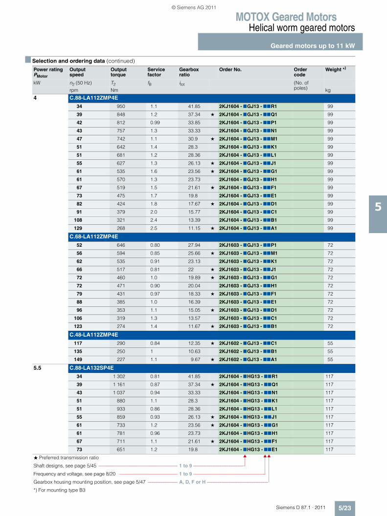
MOTOX Geared MotorsHelical worm geared motors
Geared motors up to 11 kW
5/23Siemens D 87.1 · 2011
5
4 C.88-LA112ZMP4E
34 950 1.1 41.85 2KJ1604 - 7GJ13 - 77R1 99
39 848 1.2 37.34 ★ 2KJ1604 - 7GJ13 - 77Q1 99
42 812 0.99 33.85 2KJ1604 - 7GJ13 - 77P1 99
43 757 1.3 33.33 2KJ1604 - 7GJ13 - 77N1 99
47 742 1.1 30.9 ★ 2KJ1604 - 7GJ13 - 77M1 99
51 642 1.4 28.3 2KJ1604 - 7GJ13 - 77K1 99
51 681 1.2 28.36 2KJ1604 - 7GJ13 - 77L1 99
55 627 1.3 26.13 ★ 2KJ1604 - 7GJ13 - 77J1 99
61 535 1.6 23.56 ★ 2KJ1604 - 7GJ13 - 77G1 99
61 570 1.3 23.73 2KJ1604 - 7GJ13 - 77H1 99
67 519 1.5 21.61 ★ 2KJ1604 - 7GJ13 - 77F1 99
73 475 1.7 19.8 2KJ1604 - 7GJ13 - 77E1 99
82 424 1.8 17.67 ★ 2KJ1604 - 7GJ13 - 77D1 99
91 379 2.0 15.77 2KJ1604 - 7GJ13 - 77C1 99
108 321 2.4 13.39 2KJ1604 - 7GJ13 - 77B1 99
129 268 2.5 11.15 ★ 2KJ1604 - 7GJ13 - 77A1 99
C.68-LA112ZMP4E
52 646 0.80 27.94 2KJ1603 - 7GJ13 - 77P1 72
56 594 0.85 25.66 ★ 2KJ1603 - 7GJ13 - 77M1 72
62 535 0.91 23.13 2KJ1603 - 7GJ13 - 77K1 72
66 517 0.81 22 ★ 2KJ1603 - 7GJ13 - 77J1 72
72 460 1.0 19.89 ★ 2KJ1603 - 7GJ13 - 77G1 72
72 471 0.90 20.04 2KJ1603 - 7GJ13 - 77H1 72
79 431 0.97 18.33 ★ 2KJ1603 - 7GJ13 - 77F1 72
88 385 1.0 16.39 2KJ1603 - 7GJ13 - 77E1 72
96 353 1.1 15.05 ★ 2KJ1603 - 7GJ13 - 77D1 72
106 319 1.3 13.57 2KJ1603 - 7GJ13 - 77C1 72
123 274 1.4 11.67 ★ 2KJ1603 - 7GJ13 - 77B1 72
C.48-LA112ZMP4E
117 290 0.84 12.35 ★ 2KJ1602 - 7GJ13 - 77C1 55
135 250 1 10.63 2KJ1602 - 7GJ13 - 77B1 55
149 227 1.1 9.67 ★ 2KJ1602 - 7GJ13 - 77A1 55
5.5 C.88-LA132SP4E
34 1 302 0.81 41.85 2KJ1604 - 7HG13 - 77R1 117
39 1 161 0.87 37.34 ★ 2KJ1604 - 7HG13 - 77Q1 117
43 1 037 0.94 33.33 2KJ1604 - 7HG13 - 77N1 117
51 880 1.1 28.3 2KJ1604 - 7HG13 - 77K1 117
51 933 0.86 28.36 2KJ1604 - 7HG13 - 77L1 117
55 859 0.93 26.13 ★ 2KJ1604 - 7HG13 - 77J1 117
61 733 1.2 23.56 ★ 2KJ1604 - 7HG13 - 77G1 117
61 781 0.96 23.73 2KJ1604 - 7HG13 - 77H1 117
67 711 1.1 21.61 ★ 2KJ1604 - 7HG13 - 77F1 117
73 651 1.2 19.8 2KJ1604 - 7HG13 - 77E1 117
■ Selection and ordering data (continued)
Power ratingPMotor
Output speed
Output torque
Service factor
Gearbox ratio
Order No. Order code
Weight *)
kW n2 (50 Hz) T2 fB itot (No. of poles)rpm Nm kg
� Preferred transmission ratio
Shaft designs, see page 5/45 ––––––––––––––––––––––––––––––––– 1 to 9 ––––––––––––––––––––––
Frequency and voltage, see page 8/20 ––––––––––––––––––––––––– 1 to 9 –––––––––––––––––––––––––––––––
Gearbox housing mounting position, see page 5/47 ––––––––––––– A, D, F or H –––––––––––––––––––––––––––
*) For mounting type B3
© Siemens AG 2011
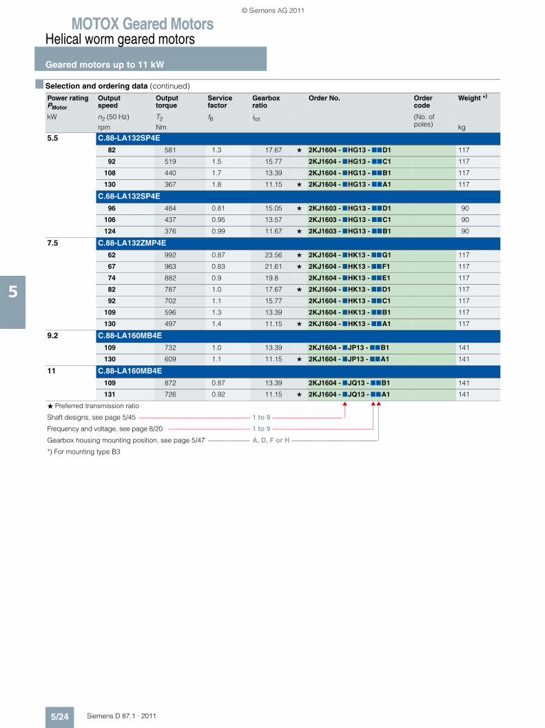
MOTOX Geared MotorsHelical worm geared motors
Geared motors up to 11 kW
5/24 Siemens D 87.1 · 2011
5
5.5 C.88-LA132SP4E
82 581 1.3 17.67 ★ 2KJ1604 - 7HG13 - 77D1 117
92 519 1.5 15.77 2KJ1604 - 7HG13 - 77C1 117
108 440 1.7 13.39 2KJ1604 - 7HG13 - 77B1 117
130 367 1.8 11.15 ★ 2KJ1604 - 7HG13 - 77A1 117
C.68-LA132SP4E
96 484 0.81 15.05 ★ 2KJ1603 - 7HG13 - 77D1 90
106 437 0.95 13.57 2KJ1603 - 7HG13 - 77C1 90
124 376 0.99 11.67 ★ 2KJ1603 - 7HG13 - 77B1 90
7.5 C.88-LA132ZMP4E
62 992 0.87 23.56 ★ 2KJ1604 - 7HK13 - 77G1 117
67 963 0.83 21.61 ★ 2KJ1604 - 7HK13 - 77F1 117
74 882 0.9 19.8 2KJ1604 - 7HK13 - 77E1 117
82 787 1.0 17.67 ★ 2KJ1604 - 7HK13 - 77D1 117
92 702 1.1 15.77 2KJ1604 - 7HK13 - 77C1 117
109 596 1.3 13.39 2KJ1604 - 7HK13 - 77B1 117
130 497 1.4 11.15 ★ 2KJ1604 - 7HK13 - 77A1 117
9.2 C.88-LA160MB4E
109 732 1.0 13.39 2KJ1604 - 7JP13 - 77B1 141
130 609 1.1 11.15 ★ 2KJ1604 - 7JP13 - 77A1 141
11 C.88-LA160MB4E
109 872 0.87 13.39 2KJ1604 - 7JQ13 - 77B1 141
131 726 0.92 11.15 ★ 2KJ1604 - 7JQ13 - 77A1 141
■ Selection and ordering data (continued)
Power ratingPMotor
Output speed
Output torque
Service factor
Gearbox ratio
Order No. Order code
Weight *)
kW n2 (50 Hz) T2 fB itot (No. of poles)rpm Nm kg
� Preferred transmission ratio
Shaft designs, see page 5/45 ––––––––––––––––––––––––––––––––– 1 to 9 ––––––––––––––––––––––
Frequency and voltage, see page 8/20 ––––––––––––––––––––––––– 1 to 9 –––––––––––––––––––––––––––––––
Gearbox housing mounting position, see page 5/47 ––––––––––––– A, D, F or H –––––––––––––––––––––––––––
*) For mounting type B3
© Siemens AG 2011
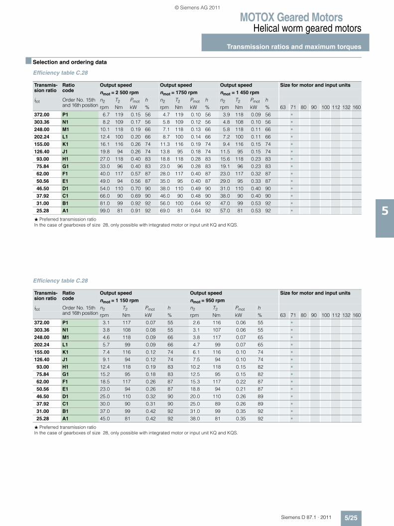
MOTOX Geared MotorsHelical worm geared motors
Transmission ratios and maximum torques
5/25Siemens D 87.1 · 2011
5
■ Selection and ordering data
Efficiency table C.28
Efficiency table C.28
Transmis-sion ratio
Ratio code
Output speed Output speed Output speed Size for motor and input units
nmot = 2 500 rpm nmot = 1750 rpm nmot = 1 450 rpm
itot Order No. 15th and 16th position
n2 T2 Pmot h n2 T2 Pmot h n2 T2 Pmot hrpm Nm kW % rpm Nm kW % rpm Nm kW % 63 71 80 90 100 112 132 160
372.00 P1 6.7 119 0.15 56 4.7 119 0.10 56 3.9 118 0.09 56 •303.36 N1 8.2 109 0.17 56 5.8 109 0.12 56 4.8 108 0.10 56 •248.00 M1 10.1 118 0.19 66 7.1 118 0.13 66 5.8 118 0.11 66 •202.24 L1 12.4 100 0.20 66 8.7 100 0.14 66 7.2 100 0.11 66 •155.00 K1 16.1 116 0.26 74 11.3 116 0.19 74 9.4 116 0.15 74 •126.40 J1 19.8 94 0.26 74 13.8 95 0.18 74 11.5 95 0.15 74 •93.00 H1 27.0 118 0.40 83 18.8 118 0.28 83 15.6 118 0.23 83 •75.84 G1 33.0 96 0.40 83 23.0 96 0.28 83 19.1 96 0.23 83 •62.00 F1 40.0 117 0.57 87 28.0 117 0.40 87 23.0 117 0.32 87 •50.56 E1 49.0 94 0.56 87 35.0 95 0.40 87 29.0 95 0.33 87 •46.50 D1 54.0 110 0.70 90 38.0 110 0.49 90 31.0 110 0.40 90 •37.92 C1 66.0 90 0.69 90 46.0 90 0.48 90 38.0 90 0.40 90 •31.00 B1 81.0 99 0.92 92 56.0 100 0.64 92 47.0 99 0.53 92 •25.28 A1 99.0 81 0.91 92 69.0 81 0.64 92 57.0 81 0.53 92 •
� Preferred transmission ratioIn the case of gearboxes of size 28, only possible with integrated motor or input unit KQ and KQS.
Transmis-sion ratio
Ratio code
Output speed Output speed Size for motor and input units
nmot = 1 150 rpm nmot = 950 rpm
itot Order No. 15th and 16th position
n2 T2 Pmot h n2 T2 Pmot hrpm Nm kW % rpm Nm kW % 63 71 80 90 100 112 132 160
372.00 P1 3.1 117 0.07 55 2.6 116 0.06 55 •303.36 N1 3.8 108 0.08 55 3.1 107 0.06 55 •248.00 M1 4.6 118 0.09 66 3.8 117 0.07 65 •202.24 L1 5.7 99 0.09 66 4.7 99 0.07 65 •155.00 K1 7.4 116 0.12 74 6.1 116 0.10 74 •126.40 J1 9.1 94 0.12 74 7.5 94 0.10 74 •93.00 H1 12.4 118 0.19 83 10.2 118 0.15 82 •75.84 G1 15.2 95 0.18 83 12.5 95 0.15 82 •62.00 F1 18.5 117 0.26 87 15.3 117 0.22 87 •50.56 E1 23.0 94 0.26 87 18.8 94 0.21 87 •46.50 D1 25.0 110 0.32 90 20.0 110 0.26 89 •37.92 C1 30.0 90 0.31 90 25.0 89 0.26 89 •31.00 B1 37.0 99 0.42 92 31.0 99 0.35 92 •25.28 A1 45.0 81 0.42 92 38.0 81 0.35 92 •
� Preferred transmission ratioIn the case of gearboxes of size 28, only possible with integrated motor or input unit KQ and KQS.
© Siemens AG 2011
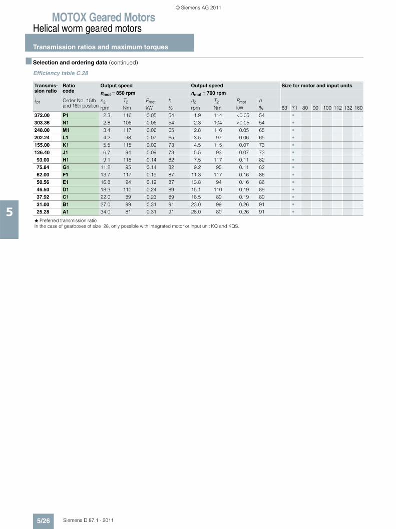
MOTOX Geared MotorsHelical worm geared motors
Transmission ratios and maximum torques
5/26 Siemens D 87.1 · 2011
5
■ Selection and ordering data (continued)
Efficiency table C.28
Transmis-sion ratio
Ratio code
Output speed Output speed Size for motor and input units
nmot = 850 rpm nmot = 700 rpm
itot Order No. 15th and 16th position
n2 T2 Pmot h n2 T2 Pmot hrpm Nm kW % rpm Nm kW % 63 71 80 90 100 112 132 160
372.00 P1 2.3 116 0.05 54 1.9 114 <0.05 54 •303.36 N1 2.8 106 0.06 54 2.3 104 <0.05 54 •248.00 M1 3.4 117 0.06 65 2.8 116 0.05 65 •202.24 L1 4.2 98 0.07 65 3.5 97 0.06 65 •155.00 K1 5.5 115 0.09 73 4.5 115 0.07 73 •126.40 J1 6.7 94 0.09 73 5.5 93 0.07 73 •93.00 H1 9.1 118 0.14 82 7.5 117 0.11 82 •75.84 G1 11.2 95 0.14 82 9.2 95 0.11 82 •62.00 F1 13.7 117 0.19 87 11.3 117 0.16 86 •50.56 E1 16.8 94 0.19 87 13.8 94 0.16 86 •46.50 D1 18.3 110 0.24 89 15.1 110 0.19 89 •37.92 C1 22.0 89 0.23 89 18.5 89 0.19 89 •31.00 B1 27.0 99 0.31 91 23.0 99 0.26 91 •25.28 A1 34.0 81 0.31 91 28.0 80 0.26 91 •
� Preferred transmission ratioIn the case of gearboxes of size 28, only possible with integrated motor or input unit KQ and KQS.
© Siemens AG 2011

MOTOX Geared MotorsHelical worm geared motors
Transmission ratios and maximum torques
5/27Siemens D 87.1 · 2011
5
■ Selection and ordering data (continued)
Efficiency table C.38-D/Z28
Transmis-sion ratio
Ratio code
Output speed Output speed Size for motor and input units
nmot = 1 750 rpm nmot = 1 450 rpm
itot Order No. 15th and 16th position
n2 T2 Pmot h n2 T2 Pmot hrpm Nm kW % rpm Nm kW % 63 71 80 90 100 112 132 160
23 503 N1 0.07 222 <0.06 45 0.06 222 <0.06 45 •20 276 M1 0.09 222 <0.06 45 0.07 222 <0.06 45 •17 420 L1 0.10 222 <0.06 45 0.08 222 <0.06 45 •16 037 K1 0.11 222 <0.06 45 0.09 222 <0.06 45 •14 579 J1 0.12 222 <0.06 45 0.10 222 <0.06 45 •12 904 H1 0.14 222 <0.06 45 0.11 222 <0.06 45 •10 808 G1 0.16 222 <0.06 45 0.13 222 <0.06 45 •9 216 F1 0.19 222 <0.06 46 0.16 222 <0.06 45 •7 833 E1 0.22 222 <0.06 46 0.19 222 <0.06 46 •6 807 D1 0.26 222 <0.06 46 0.21 222 <0.06 46 •5 925 C1 0.30 222 <0.06 46 0.24 222 <0.06 46 •5 345 B1 0.33 222 <0.06 46 0.27 222 <0.06 46 •4 717 A1 0.37 222 <0.06 46 0.31 222 <0.06 46 •4 222 B2 0.41 222 <0.06 47 0.34 222 <0.06 46 •3 749 A2 0.47 222 <0.06 47 0.39 222 <0.06 46 •3 286 X1 0.53 222 <0.06 47 0.44 222 <0.06 47 •2 941 W1 0.60 222 <0.06 47 0.49 222 <0.06 47 •2 610 V1 0.67 222 <0.06 48 0.56 222 <0.06 47 •2 288 U1 0.76 223 <0.06 48 0.63 222 <0.06 47 •2 011 T1 0.87 223 <0.06 48 0.72 222 <0.06 48 •1 817 S1 0.96 223 <0.06 49 0.80 223 <0.06 48 •1 583 R1 1.11 223 <0.06 49 0.92 223 <0.06 49 •1 422 Q1 1.23 223 <0.06 50 1.02 223 <0.06 49 •1 284 P1 1.36 223 0.06 50 1.13 223 <0.06 49 •1 164 N1 1.50 223 0.07 51 1.25 223 <0.06 50 •1 059 M1 1.65 223 0.08 51 1.37 223 0.06 50 •
937 L1 1.87 223 0.08 52 1.55 223 0.07 51 •865 K1 2.02 223 0.09 53 1.68 223 0.08 51 •745 J1 2.35 223 0.10 54 1.95 223 0.09 52 •677 H1 2.59 224 0.11 54 2.14 223 0.09 53 •615 G1 2.84 224 0.12 55 2.36 223 0.10 54 •558 F1 3.14 224 0.13 56 2.60 224 0.11 55 •508 E1 3.45 224 0.14 57 2.86 224 0.12 55 •449 D1 3.90 224 0.16 58 3.23 224 0.13 56 •414 C1 4.22 225 0.17 59 3.50 224 0.14 57 •357 B1 4.90 225 0.19 60 4.06 225 0.16 58 •324 A1 5.40 225 0.21 61 4.47 225 0.18 59 •
� Preferred transmission ratioIn the case of gearboxes of size 28, only possible with integrated motor or input unit KQ and KQS.
© Siemens AG 2011

MOTOX Geared MotorsHelical worm geared motors
Transmission ratios and maximum torques
5/28 Siemens D 87.1 · 2011
5
■ Selection and ordering data (continued)
Efficiency table C.38
Transmis-sion ratio
Ratio code
Output speed Output speed Output speed Size for motor and input units
nmot = 1 750 rpm nmot = 1 450 rpm nmot = 1 150 rpm
itot Order No. 15th and 16th position
n2 T2 Pmot h n2 T2 Pmot h n2 T2 Pmot hrpm Nm kW % rpm Nm kW % rpm Nm kW % 63 71 80 90 100 112 132 160
320.67 ★ K2 5.5 225 0.21 62 4.5 225 0.18 60 3.6 224 0.15 58 • • •
284.70 J2 6.1 226 0.23 63 5.1 225 0.20 62 4.0 224 0.16 59 • • •249.60 ★ H2 7.0 226 0.26 64 5.8 226 0.22 63 4.6 225 0.18 61 • • • •
223.36 G2 7.8 227 0.28 65 6.5 226 0.24 64 5.1 225 0.20 62 • • • •198.25 ★ F2 8.8 227 0.32 66 7.3 226 0.27 65 5.8 225 0.22 63 • • • •
173.73 E2 10.1 228 0.36 67 8.3 227 0.30 66 6.6 226 0.24 64 • • • •152.75 ★ D2 11.5 228 0.41 68 9.5 227 0.34 67 7.5 226 0.27 65 • • • •
138.00 C2 12.7 229 0.45 68 10.5 228 0.37 67 8.3 227 0.30 66 • • • •120.25 ★ B2 14.6 230 0.51 68 12.1 229 0.43 68 9.6 228 0.34 67 • • • •
108.00 A2 16.2 226 0.56 69 13.4 229 0.47 68 10.6 228 0.38 67 • • • •97.50 ★ X1 17.9 219 0.60 69 14.9 230 0.53 68 11.8 229 0.42 68 • • • • •
88.40 W1 19.8 211 0.64 69 16.4 224 0.56 69 13.0 229 0.46 68 • • • • •80.44 ★ V1 22.0 203 0.68 69 18.0 217 0.60 69 14.3 230 0.50 68 • • • • •
71.12 U1 25.0 195 0.74 69 20.0 210 0.64 69 16.2 225 0.56 69 • • • • •65.68 ★ T1 27.0 191 0.78 69 22.0 204 0.68 69 17.5 220 0.59 69 • • • • •
60.30 ★ S1 29.0 204 0.71 87 24.0 202 0.59 87 19.1 199 0.47 85 • • •
53.53 R1 33.0 245 0.96 88 27.0 243 0.79 87 21.0 239 0.61 86 • • •46.93 ★ Q1 37.0 232 1.02 88 31.0 231 0.85 88 25.0 228 0.69 87 • • • •
42.00 P1 42.0 222 1.10 89 35.0 220 0.92 88 27.0 218 0.71 87 • • • •37.28 ★ N1 47.0 232 1.28 89 39.0 231 1.07 89 31.0 229 0.85 88 • • • •
32.67 M1 54.0 192 1.22 89 44.0 192 0.99 89 35.0 190 0.79 88 • • • •28.72 ★ L1 61.0 208 1.49 89 50.0 207 1.22 89 40.0 206 0.97 89 • • • •
25.95 K1 67.0 209 1.64 89 56.0 208 1.37 89 44.0 207 1.08 89 • • • •22.61 ★ J1 77.0 206 1.86 89 64.0 206 1.55 89 51.0 205 1.23 89 • • • •
20.31 H1 86.0 196 1.98 89 71.0 196 1.63 89 57.0 196 1.31 89 • • • •18.33 ★ G1 95.0 199 2.21 89 79.0 206 1.91 89 63.0 206 1.52 89 • • • • •
16.62 F1 105.0 191 2.34 89 87.0 196 2.00 89 69.0 196 1.59 89 • • • • •15.13 ★ E1 116.0 183 2.49 89 96.0 187 2.10 89 76.0 187 1.66 89 • • • • •
13.37 D1 131.0 165 2.53 89 108.0 165 2.09 89 86.0 165 1.66 89 • • • • •12.35 ★ C1 142.0 169 2.81 89 117.0 172 2.36 89 93.0 172 1.88 89 • • • • •
10.63 B1 165.0 155 3.00 89 136.0 173 2.76 89 108.0 183 2.31 89 • • • • •9.67 ★ A1 181.0 141 3.00 89 150.0 170 3.00 89 119.0 176 2.46 89 • • • • •
� Preferred transmission ratioIn the case of gearboxes of size 28, only possible with integrated motor or input unit KQ and KQS.
© Siemens AG 2011
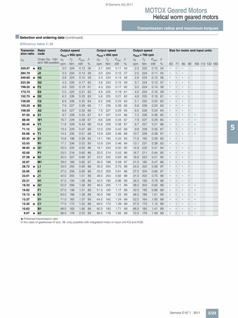
MOTOX Geared MotorsHelical worm geared motors
Transmission ratios and maximum torques
5/29Siemens D 87.1 · 2011
5
■ Selection and ordering data (continued)
Efficiency table C.38
Transmis-sion ratio
Ratio code
Output speed Output speed Output speed Size for motor and input units
nmot = 950 rpm nmot = 850 rpm nmot = 700 rpm
itot Order No. 15th and 16th position
n2 T2 Pmot h n2 T2 Pmot h n2 T2 Pmot hrpm Nm kW % rpm Nm kW % rpm Nm kW % 63 71 80 90 100 112 132 160
320.67 ★ K2 3.0 224 0.12 56 2.7 224 0.11 56 2.2 223 0.10 54 • • •
284.70 J2 3.3 224 0.13 58 3.0 224 0.12 57 2.5 224 0.11 55 • • •249.60 ★ H2 3.8 224 0.15 59 3.4 224 0.14 58 2.8 224 0.12 56 • • • •
223.36 G2 4.3 225 0.17 60 3.8 224 0.15 59 3.1 224 0.13 57 • • • •198.25 ★ F2 4.8 225 0.19 61 4.3 225 0.17 60 3.5 224 0.14 58 • • • •
173.73 E2 5.5 225 0.21 62 4.9 225 0.19 61 4.0 224 0.16 59 • • • •152.75 ★ D2 6.2 226 0.23 63 5.6 225 0.21 62 4.6 225 0.18 61 • • • •
138.00 C2 6.9 226 0.25 64 6.2 226 0.23 63 5.1 225 0.20 62 • • • •120.25 ★ B2 7.9 227 0.29 65 7.1 226 0.26 65 5.8 226 0.22 63 • • • •
108.00 A2 8.8 227 0.32 66 7.9 227 0.29 65 6.5 226 0.24 64 • • • •97.50 ★ X1 9.7 228 0.35 67 8.7 227 0.31 66 7.2 226 0.26 65 • • • • •
88.40 W1 10.7 228 0.38 67 9.6 228 0.34 67 7.9 227 0.29 65 • • • • •80.44 ★ V1 11.8 229 0.42 68 10.6 228 0.38 67 8.7 227 0.31 66 • • • • •
71.12 U1 13.4 229 0.47 68 12.0 229 0.42 68 9.8 228 0.35 67 • • • • •65.68 ★ T1 14.5 230 0.51 68 12.9 229 0.46 68 10.7 228 0.38 67 • • • • •
60.30 ★ S1 15.8 196 0.39 84 14.1 195 0.34 84 11.6 192 0.28 82 • • •
53.53 R1 17.7 236 0.52 85 15.9 234 0.46 84 13.1 231 0.38 83 • • •46.93 ★ Q1 20.0 225 0.55 86 18.1 223 0.50 85 14.9 220 0.41 84 • • • •
42.00 P1 23.0 216 0.60 86 20.0 214 0.52 86 16.7 211 0.44 85 • • • •37.28 ★ N1 25.0 227 0.68 87 23.0 225 0.63 86 18.8 222 0.51 85 • • • •
32.67 M1 29.0 189 0.65 87 26.0 188 0.59 87 21.0 185 0.47 86 • • • •28.72 ★ L1 33.0 205 0.80 88 30.0 204 0.73 88 24.0 202 0.58 87 • • • •
25.95 K1 37.0 206 0.90 88 33.0 205 0.81 88 27.0 204 0.66 87 • • • •22.61 ★ J1 42.0 205 1.01 89 38.0 204 0.92 88 31.0 202 0.75 88 • • • •
20.31 H1 47.0 195 1.08 89 42.0 195 0.96 89 34.0 193 0.78 88 • • • •18.33 ★ G1 52.0 206 1.26 89 46.0 205 1.11 89 38.0 204 0.92 88 • • • • •
16.62 F1 57.0 196 1.31 89 51.0 195 1.17 89 42.0 195 0.96 89 • • • • •15.13 ★ E1 63.0 186 1.38 89 56.0 186 1.22 89 46.0 186 1.01 89 • • • • •
13.37 D1 71.0 165 1.37 89 64.0 165 1.24 89 52.0 164 1.00 89 • • • • •12.35 ★ C1 77.0 172 1.55 89 69.0 172 1.39 89 57.0 172 1.15 89 • • • • •
10.63 B1 89.0 183 1.90 89 80.0 183 1.71 89 66.0 182 1.41 89 • • • • •9.67 ★ A1 98.0 176 2.02 89 88.0 176 1.82 89 72.0 176 1.49 89 • • • • •
� Preferred transmission ratioIn the case of gearboxes of size 28, only possible with integrated motor or input unit KQ and KQS.
© Siemens AG 2011
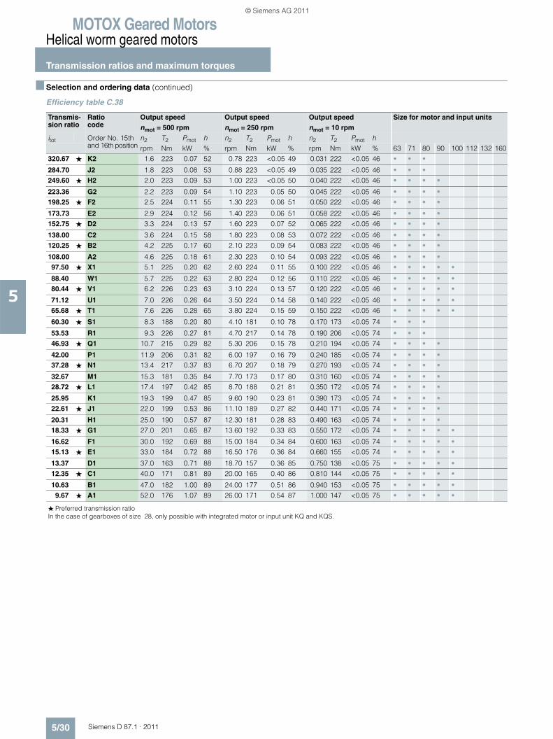
MOTOX Geared MotorsHelical worm geared motors
Transmission ratios and maximum torques
5/30 Siemens D 87.1 · 2011
5
■ Selection and ordering data (continued)
Efficiency table C.38
Transmis-sion ratio
Ratio code
Output speed Output speed Output speed Size for motor and input units
nmot = 500 rpm nmot = 250 rpm nmot = 10 rpm
itot Order No. 15th and 16th position
n2 T2 Pmot h n2 T2 Pmot h n2 T2 Pmot hrpm Nm kW % rpm Nm kW % rpm Nm kW % 63 71 80 90 100 112 132 160
320.67 ★ K2 1.6 223 0.07 52 0.78 223 <0.05 49 0.031 222 <0.05 46 • • •
284.70 J2 1.8 223 0.08 53 0.88 223 <0.05 49 0.035 222 <0.05 46 • • •249.60 ★ H2 2.0 223 0.09 53 1.00 223 <0.05 50 0.040 222 <0.05 46 • • • •
223.36 G2 2.2 223 0.09 54 1.10 223 0.05 50 0.045 222 <0.05 46 • • • •198.25 ★ F2 2.5 224 0.11 55 1.30 223 0.06 51 0.050 222 <0.05 46 • • • •
173.73 E2 2.9 224 0.12 56 1.40 223 0.06 51 0.058 222 <0.05 46 • • • •152.75 ★ D2 3.3 224 0.13 57 1.60 223 0.07 52 0.065 222 <0.05 46 • • • •
138.00 C2 3.6 224 0.15 58 1.80 223 0.08 53 0.072 222 <0.05 46 • • • •120.25 ★ B2 4.2 225 0.17 60 2.10 223 0.09 54 0.083 222 <0.05 46 • • • •
108.00 A2 4.6 225 0.18 61 2.30 223 0.10 54 0.093 222 <0.05 46 • • • •97.50 ★ X1 5.1 225 0.20 62 2.60 224 0.11 55 0.100 222 <0.05 46 • • • • •
88.40 W1 5.7 225 0.22 63 2.80 224 0.12 56 0.110 222 <0.05 46 • • • • •80.44 ★ V1 6.2 226 0.23 63 3.10 224 0.13 57 0.120 222 <0.05 46 • • • • •
71.12 U1 7.0 226 0.26 64 3.50 224 0.14 58 0.140 222 <0.05 46 • • • • •65.68 ★ T1 7.6 226 0.28 65 3.80 224 0.15 59 0.150 222 <0.05 46 • • • • •
60.30 ★ S1 8.3 188 0.20 80 4.10 181 0.10 78 0.170 173 <0.05 74 • • •
53.53 R1 9.3 226 0.27 81 4.70 217 0.14 78 0.190 206 <0.05 74 • • •46.93 ★ Q1 10.7 215 0.29 82 5.30 206 0.15 78 0.210 194 <0.05 74 • • • •
42.00 P1 11.9 206 0.31 82 6.00 197 0.16 79 0.240 185 <0.05 74 • • • •37.28 ★ N1 13.4 217 0.37 83 6.70 207 0.18 79 0.270 193 <0.05 74 • • • •
32.67 M1 15.3 181 0.35 84 7.70 173 0.17 80 0.310 160 <0.05 74 • • • •28.72 ★ L1 17.4 197 0.42 85 8.70 188 0.21 81 0.350 172 <0.05 74 • • • •
25.95 K1 19.3 199 0.47 85 9.60 190 0.23 81 0.390 173 <0.05 74 • • • •22.61 ★ J1 22.0 199 0.53 86 11.10 189 0.27 82 0.440 171 <0.05 74 • • • •
20.31 H1 25.0 190 0.57 87 12.30 181 0.28 83 0.490 163 <0.05 74 • • • •18.33 ★ G1 27.0 201 0.65 87 13.60 192 0.33 83 0.550 172 <0.05 74 • • • • •
16.62 F1 30.0 192 0.69 88 15.00 184 0.34 84 0.600 163 <0.05 74 • • • • •15.13 ★ E1 33.0 184 0.72 88 16.50 176 0.36 84 0.660 155 <0.05 74 • • • • •
13.37 D1 37.0 163 0.71 88 18.70 157 0.36 85 0.750 138 <0.05 75 • • • • •12.35 ★ C1 40.0 171 0.81 89 20.00 165 0.40 86 0.810 144 <0.05 75 • • • • •
10.63 B1 47.0 182 1.00 89 24.00 177 0.51 86 0.940 153 <0.05 75 • • • • •9.67 ★ A1 52.0 176 1.07 89 26.00 171 0.54 87 1.000 147 <0.05 75 • • • • •
� Preferred transmission ratioIn the case of gearboxes of size 28, only possible with integrated motor or input unit KQ and KQS.
© Siemens AG 2011

MOTOX Geared MotorsHelical worm geared motors
Transmission ratios and maximum torques
5/31Siemens D 87.1 · 2011
5
■ Selection and ordering data (continued)
Efficiency table C.48-D/Z28
Transmis-sion ratio
Ratio code
Output speed Output speed Size for motor and input units
nmot = 1 750 rpm nmot = 1 450 rpm
itot Order No. 15th and 16th position
n2 T2 Pmot h n2 T2 Pmot hrpm Nm kW % rpm Nm kW % 63 71 80 90 100 112 132 160
23 503 N1 0.07 364 <0.06 47 0.06 364 <0.06 47 •20 276 M1 0.09 364 <0.06 47 0.07 364 <0.06 47 •17 420 L1 0.10 364 <0.06 47 0.08 364 <0.06 47 •16 037 K1 0.11 364 <0.06 47 0.09 364 <0.06 47 •14 579 J1 0.12 364 <0.06 47 0.10 364 <0.06 47 •12 904 H1 0.14 364 <0.06 47 0.11 364 <0.06 47 •10 808 G1 0.16 364 <0.06 47 0.13 364 <0.06 47 •9 216 F1 0.19 364 <0.06 47 0.16 364 <0.06 47 •7 833 E1 0.22 364 <0.06 48 0.19 364 <0.06 47 •6 807 D1 0.26 364 <0.06 48 0.21 364 <0.06 47 •5 925 C1 0.30 364 <0.06 48 0.24 364 <0.06 48 •5 345 B1 0.33 364 <0.06 48 0.27 364 <0.06 48 •4 717 A1 0.37 364 <0.06 48 0.31 364 <0.06 48 •4 222 B2 0.41 364 <0.06 48 0.34 364 <0.06 48 •3 749 A2 0.47 364 <0.06 49 0.39 364 <0.06 48 •3 286 X1 0.53 364 <0.06 49 0.44 364 <0.06 49 •2 941 W1 0.60 364 <0.06 49 0.49 364 <0.06 49 •2 610 V1 0.67 364 <0.06 50 0.56 364 <0.06 49 •2 288 U1 0.76 365 <0.06 50 0.63 364 <0.06 49 •2 011 T1 0.87 365 0.07 51 0.72 364 <0.06 50 •1 817 S1 0.96 365 0.07 51 0.80 365 0.06 50 •1 583 R1 1.11 365 0.08 52 0.92 365 0.07 51 •1 422 Q1 1.23 365 0.09 52 1.02 365 0.08 51 •1 284 P1 1.36 365 0.10 53 1.13 365 0.08 52 •1 164 N1 1.50 365 0.11 53 1.25 365 0.09 52 •1 059 M1 1.65 366 0.12 54 1.37 365 0.10 53 •
937 L1 1.87 366 0.13 55 1.55 365 0.11 53 •865 K1 2.02 366 0.14 55 1.68 366 0.12 54 •745 J1 2.35 366 0.16 56 1.95 366 0.14 55 •677 H1 2.59 367 0.17 57 2.14 366 0.15 56 •615 G1 2.84 367 0.19 58 2.36 366 0.16 57 •558 F1 3.14 367 0.20 59 2.60 367 0.17 57 •508 E1 3.45 368 0.22 60 2.86 367 0.19 58 •449 D1 3.90 368 0.25 61 3.23 367 0.21 59 •414 C1 4.22 368 0.26 62 3.50 368 0.22 60 •357 B1 4.90 369 0.30 64 4.06 368 0.25 62 •324 A1 5.40 370 0.32 64 4.47 369 0.28 63 •
� Preferred transmission ratioIn the case of gearboxes of size 28, only possible with integrated motor or input unit KQ and KQS.
© Siemens AG 2011

MOTOX Geared MotorsHelical worm geared motors
Transmission ratios and maximum torques
5/32 Siemens D 87.1 · 2011
5
■ Selection and ordering data (continued)
Efficiency table C.48
Transmis-sion ratio
Ratio code
Output speed Output speed Output speed Size for motor and input units
nmot = 1 750 rpm nmot = 1 450 rpm nmot = 1 150 rpm
itot Order No. 15th and 16th position
n2 T2 Pmot h n2 T2 Pmot h n2 T2 Pmot hrpm Nm kW % rpm Nm kW % rpm Nm kW % 63 71 80 90 100 112 132 160
320.67 ★ K2 5.5 370 0.32 66 4.5 369 0.27 64 3.6 368 0.23 61 • • •
284.70 J2 6.1 370 0.35 67 5.1 369 0.30 65 4.0 368 0.25 63 • • •249.60 ★ H2 7.0 371 0.40 68 5.8 370 0.34 66 4.6 369 0.28 64 • • • •
223.36 G2 7.8 372 0.44 69 6.5 371 0.38 67 5.1 369 0.30 65 • • • •198.25 ★ F2 8.8 373 0.49 70 7.3 372 0.42 68 5.8 370 0.34 66 • • • •
173.73 E2 10.1 374 0.56 70 8.3 373 0.47 69 6.6 371 0.38 67 • • • •152.75 ★ D2 11.5 375 0.64 71 9.5 374 0.53 70 7.5 372 0.43 68 • • • •
138.00 C2 12.7 377 0.70 71 10.5 375 0.58 71 8.3 373 0.47 69 • • • •120.25 ★ B2 14.6 363 0.78 72 12.1 376 0.67 71 9.6 374 0.54 70 • • • •
108.00 A2 16.2 350 0.83 72 13.4 377 0.74 71 10.6 375 0.59 71 • • • •97.50 ★ X1 17.9 339 0.88 72 14.9 378 0.82 72 11.8 376 0.65 71 • • • • •
88.40 W1 19.8 329 0.95 72 16.4 380 0.91 72 13.0 375 0.72 71 • • • • •80.44 ★ V1 22.0 318 1.02 72 18.0 381 1.00 72 14.3 365 0.76 72 • • • • •
71.12 U1 25.0 305 1.11 72 20.0 382 1.11 72 16.2 352 0.83 72 • • • • •65.68 ★ T1 27.0 297 1.17 72 22.0 384 1.23 72 17.5 343 0.87 72 • • • • •
56.55 ★ S1 31.0 285 1.28 72 26.0 386 1.46 72 20.0 329 0.96 72 • • • • •
51.41 R1 34.0 276 1.37 72 28.0 387 1.58 72 22.0 319 1.02 72 • • • • •46.93 ★ Q1 37.0 293 1.27 89 31.0 292 1.07 89 25.0 289 0.86 88 • • • •
42.00 P1 42.0 320 1.57 90 35.0 318 1.31 89 27.0 316 1.01 88 • • • •37.28 ★ N1 47.0 267 1.47 90 39.0 267 1.22 89 31.0 265 0.97 89 • • • •
32.67 M1 54.0 267 1.68 90 44.0 266 1.37 90 35.0 265 1.09 89 • • • •28.72 ★ L1 61.0 289 2.05 90 50.0 289 1.68 90 40.0 288 1.35 89 • • • •
25.95 K1 67.0 277 2.17 90 56.0 277 1.81 90 44.0 277 1.42 90 • • • •22.61 ★ J1 77.0 270 2.42 90 64.0 270 2.02 90 51.0 270 1.61 90 • • • •
20.31 H1 86.0 281 2.82 90 71.0 281 2.33 90 57.0 281 1.87 90 • • • •18.33 ★ G1 95.0 300 3.32 90 79.0 300 2.76 90 63.0 300 2.20 90 • • • • •
16.62 F1 105.0 291 3.56 90 87.0 293 2.97 90 69.0 293 2.35 90 • • • • •15.13 ★ E1 116.0 266 3.60 90 96.0 266 2.98 90 76.0 266 2.36 90 • • • • •
13.37 D1 131.0 236 3.60 90 108.0 236 2.96 90 86.0 236 2.36 90 • • • • •12.35 ★ C1 142.0 242 4.00 90 117.0 249 3.39 90 93.0 249 2.69 90 • • • • •
10.63 B1 165.0 208 4.00 90 136.0 252 4.00 90 108.0 254 3.20 90 • • • • •9.67 ★ A1 181.0 189 4.00 90 150.0 229 4.00 90 119.0 243 3.37 90 • • • • •
� Preferred transmission ratioIn the case of gearboxes of size 28, only possible with integrated motor or input unit KQ and KQS.
© Siemens AG 2011
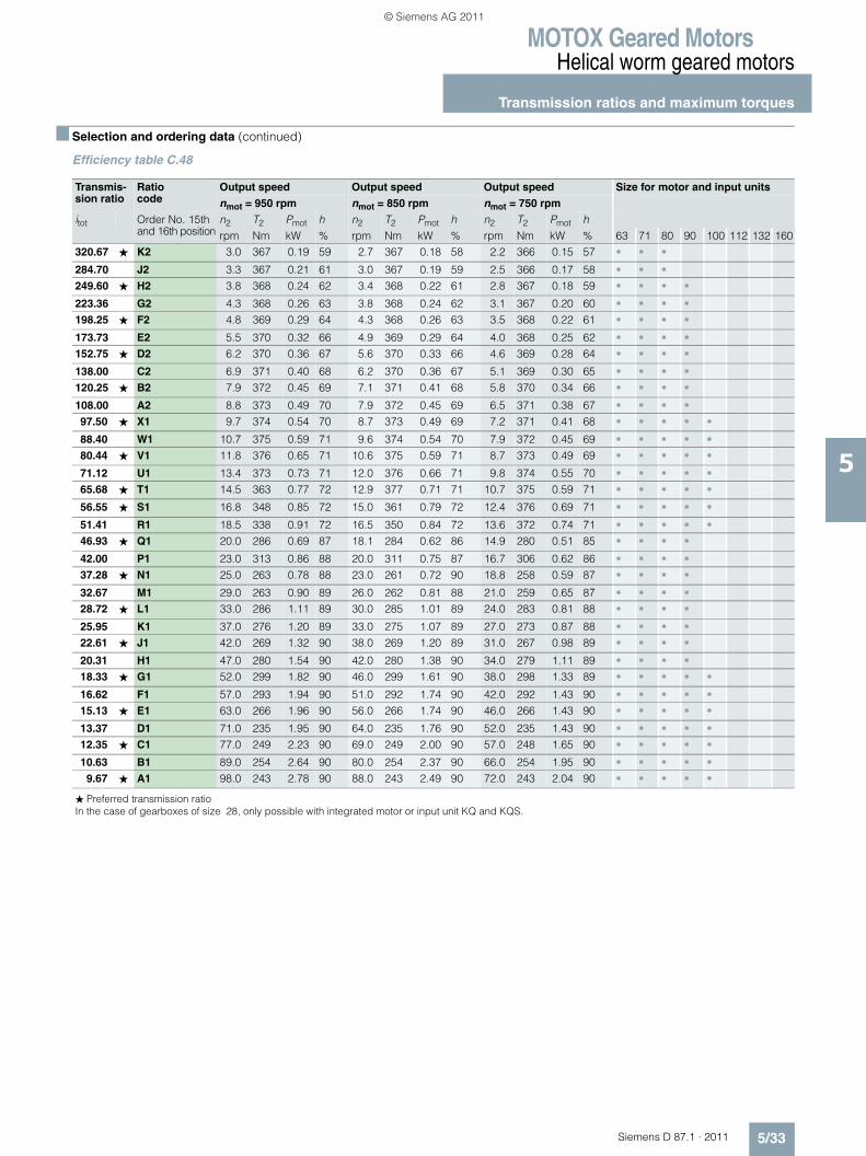
MOTOX Geared MotorsHelical worm geared motors
Transmission ratios and maximum torques
5/33Siemens D 87.1 · 2011
5
■ Selection and ordering data (continued)
Efficiency table C.48
Transmis-sion ratio
Ratio code
Output speed Output speed Output speed Size for motor and input units
nmot = 950 rpm nmot = 850 rpm nmot = 750 rpm
itot Order No. 15th and 16th position
n2 T2 Pmot h n2 T2 Pmot h n2 T2 Pmot hrpm Nm kW % rpm Nm kW % rpm Nm kW % 63 71 80 90 100 112 132 160
320.67 ★ K2 3.0 367 0.19 59 2.7 367 0.18 58 2.2 366 0.15 57 • • •
284.70 J2 3.3 367 0.21 61 3.0 367 0.19 59 2.5 366 0.17 58 • • •249.60 ★ H2 3.8 368 0.24 62 3.4 368 0.22 61 2.8 367 0.18 59 • • • •
223.36 G2 4.3 368 0.26 63 3.8 368 0.24 62 3.1 367 0.20 60 • • • •198.25 ★ F2 4.8 369 0.29 64 4.3 368 0.26 63 3.5 368 0.22 61 • • • •
173.73 E2 5.5 370 0.32 66 4.9 369 0.29 64 4.0 368 0.25 62 • • • •152.75 ★ D2 6.2 370 0.36 67 5.6 370 0.33 66 4.6 369 0.28 64 • • • •
138.00 C2 6.9 371 0.40 68 6.2 370 0.36 67 5.1 369 0.30 65 • • • •120.25 ★ B2 7.9 372 0.45 69 7.1 371 0.41 68 5.8 370 0.34 66 • • • •
108.00 A2 8.8 373 0.49 70 7.9 372 0.45 69 6.5 371 0.38 67 • • • •97.50 ★ X1 9.7 374 0.54 70 8.7 373 0.49 69 7.2 371 0.41 68 • • • • •
88.40 W1 10.7 375 0.59 71 9.6 374 0.54 70 7.9 372 0.45 69 • • • • •80.44 ★ V1 11.8 376 0.65 71 10.6 375 0.59 71 8.7 373 0.49 69 • • • • •
71.12 U1 13.4 373 0.73 71 12.0 376 0.66 71 9.8 374 0.55 70 • • • • •65.68 ★ T1 14.5 363 0.77 72 12.9 377 0.71 71 10.7 375 0.59 71 • • • • •
56.55 ★ S1 16.8 348 0.85 72 15.0 361 0.79 72 12.4 376 0.69 71 • • • • •
51.41 R1 18.5 338 0.91 72 16.5 350 0.84 72 13.6 372 0.74 71 • • • • •46.93 ★ Q1 20.0 286 0.69 87 18.1 284 0.62 86 14.9 280 0.51 85 • • • •
42.00 P1 23.0 313 0.86 88 20.0 311 0.75 87 16.7 306 0.62 86 • • • •37.28 ★ N1 25.0 263 0.78 88 23.0 261 0.72 90 18.8 258 0.59 87 • • • •
32.67 M1 29.0 263 0.90 89 26.0 262 0.81 88 21.0 259 0.65 87 • • • •28.72 ★ L1 33.0 286 1.11 89 30.0 285 1.01 89 24.0 283 0.81 88 • • • •
25.95 K1 37.0 276 1.20 89 33.0 275 1.07 89 27.0 273 0.87 88 • • • •22.61 ★ J1 42.0 269 1.32 90 38.0 269 1.20 89 31.0 267 0.98 89 • • • •
20.31 H1 47.0 280 1.54 90 42.0 280 1.38 90 34.0 279 1.11 89 • • • •18.33 ★ G1 52.0 299 1.82 90 46.0 299 1.61 90 38.0 298 1.33 89 • • • • •
16.62 F1 57.0 293 1.94 90 51.0 292 1.74 90 42.0 292 1.43 90 • • • • •15.13 ★ E1 63.0 266 1.96 90 56.0 266 1.74 90 46.0 266 1.43 90 • • • • •
13.37 D1 71.0 235 1.95 90 64.0 235 1.76 90 52.0 235 1.43 90 • • • • •12.35 ★ C1 77.0 249 2.23 90 69.0 249 2.00 90 57.0 248 1.65 90 • • • • •
10.63 B1 89.0 254 2.64 90 80.0 254 2.37 90 66.0 254 1.95 90 • • • • •9.67 ★ A1 98.0 243 2.78 90 88.0 243 2.49 90 72.0 243 2.04 90 • • • • •
� Preferred transmission ratioIn the case of gearboxes of size 28, only possible with integrated motor or input unit KQ and KQS.
© Siemens AG 2011
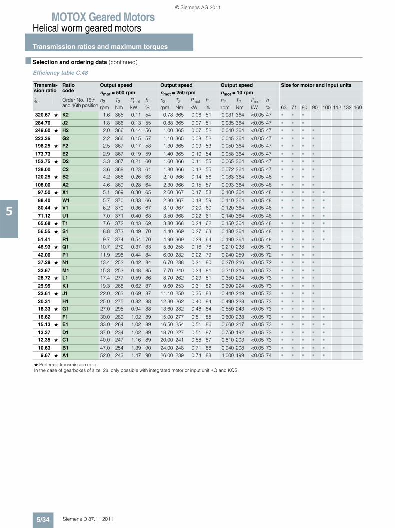
MOTOX Geared MotorsHelical worm geared motors
Transmission ratios and maximum torques
5/34 Siemens D 87.1 · 2011
5
■ Selection and ordering data (continued)
Efficiency table C.48
Transmis-sion ratio
Ratio code
Output speed Output speed Output speed Size for motor and input units
nmot = 500 rpm nmot = 250 rpm nmot = 10 rpm
itot Order No. 15th and 16th position
n2 T2 Pmot h n2 T2 Pmot h n2 T2 Pmot hrpm Nm kW % rpm Nm kW % rpm Nm kW % 63 71 80 90 100 112 132 160
320.67 ★ K2 1.6 365 0.11 54 0.78 365 0.06 51 0.031 364 <0.05 47 • • •
284.70 J2 1.8 366 0.13 55 0.88 365 0.07 51 0.035 364 <0.05 47 • • •249.60 ★ H2 2.0 366 0.14 56 1.00 365 0.07 52 0.040 364 <0.05 47 • • • •
223.36 G2 2.2 366 0.15 57 1.10 365 0.08 52 0.045 364 <0.05 47 • • • •198.25 ★ F2 2.5 367 0.17 58 1.30 365 0.09 53 0.050 364 <0.05 47 • • • •
173.73 E2 2.9 367 0.19 59 1.40 365 0.10 54 0.058 364 <0.05 47 • • • •152.75 ★ D2 3.3 367 0.21 60 1.60 366 0.11 55 0.065 364 <0.05 47 • • • •
138.00 C2 3.6 368 0.23 61 1.80 366 0.12 55 0.072 364 <0.05 47 • • • •120.25 ★ B2 4.2 368 0.26 63 2.10 366 0.14 56 0.083 364 <0.05 48 • • • •
108.00 A2 4.6 369 0.28 64 2.30 366 0.15 57 0.093 364 <0.05 48 • • • •97.50 ★ X1 5.1 369 0.30 65 2.60 367 0.17 58 0.100 364 <0.05 48 • • • • •
88.40 W1 5.7 370 0.33 66 2.80 367 0.18 59 0.110 364 <0.05 48 • • • • •80.44 ★ V1 6.2 370 0.36 67 3.10 367 0.20 60 0.120 364 <0.05 48 • • • • •
71.12 U1 7.0 371 0.40 68 3.50 368 0.22 61 0.140 364 <0.05 48 • • • • •65.68 ★ T1 7.6 372 0.43 69 3.80 368 0.24 62 0.150 364 <0.05 48 • • • • •
56.55 ★ S1 8.8 373 0.49 70 4.40 369 0.27 63 0.180 364 <0.05 48 • • • • •
51.41 R1 9.7 374 0.54 70 4.90 369 0.29 64 0.190 364 <0.05 48 • • • • •46.93 ★ Q1 10.7 272 0.37 83 5.30 258 0.18 78 0.210 238 <0.05 72 • • • •
42.00 P1 11.9 298 0.44 84 6.00 282 0.22 79 0.240 259 <0.05 72 • • • •37.28 ★ N1 13.4 252 0.42 84 6.70 238 0.21 80 0.270 216 <0.05 72 • • • •
32.67 M1 15.3 253 0.48 85 7.70 240 0.24 81 0.310 216 <0.05 73 • • • •28.72 ★ L1 17.4 277 0.59 86 8.70 262 0.29 81 0.350 234 <0.05 73 • • • •
25.95 K1 19.3 268 0.62 87 9.60 253 0.31 82 0.390 224 <0.05 73 • • • •22.61 ★ J1 22.0 263 0.69 87 11.10 250 0.35 83 0.440 219 <0.05 73 • • • •
20.31 H1 25.0 275 0.82 88 12.30 262 0.40 84 0.490 228 <0.05 73 • • • •18.33 ★ G1 27.0 295 0.94 88 13.60 282 0.48 84 0.550 243 <0.05 73 • • • • •
16.62 F1 30.0 289 1.02 89 15.00 277 0.51 85 0.600 238 <0.05 73 • • • • •15.13 ★ E1 33.0 264 1.02 89 16.50 254 0.51 86 0.660 217 <0.05 73 • • • • •
13.37 D1 37.0 234 1.02 89 18.70 227 0.51 87 0.750 192 <0.05 73 • • • • •12.35 ★ C1 40.0 247 1.16 89 20.00 241 0.58 87 0.810 203 <0.05 73 • • • • •
10.63 B1 47.0 254 1.39 90 24.00 248 0.71 88 0.940 208 <0.05 73 • • • • •9.67 ★ A1 52.0 243 1.47 90 26.00 239 0.74 88 1.000 199 <0.05 74 • • • • •
� Preferred transmission ratioIn the case of gearboxes of size 28, only possible with integrated motor or input unit KQ and KQS.
© Siemens AG 2011
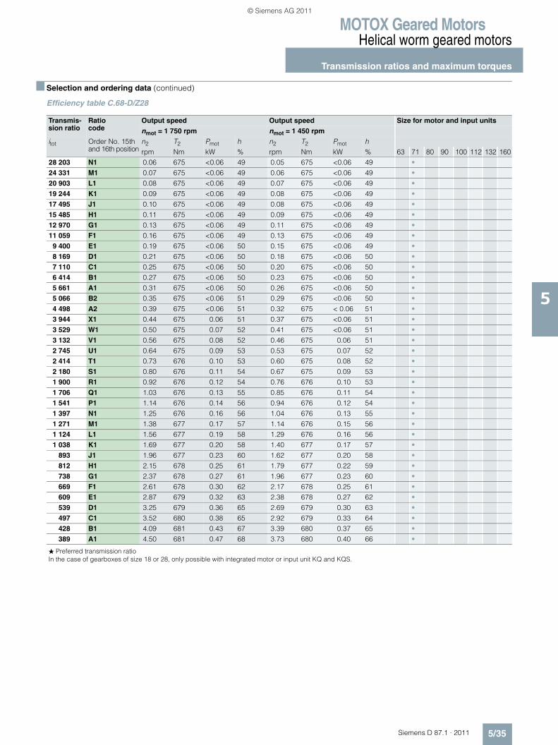
MOTOX Geared MotorsHelical worm geared motors
Transmission ratios and maximum torques
5/35Siemens D 87.1 · 2011
5
■ Selection and ordering data (continued)
Efficiency table C.68-D/Z28
Transmis-sion ratio
Ratio code
Output speed Output speed Size for motor and input units
nmot = 1 750 rpm nmot = 1 450 rpm
itot Order No. 15th and 16th position
n2 T2 Pmot h n2 T2 Pmot hrpm Nm kW % rpm Nm kW % 63 71 80 90 100 112 132 160
28 203 N1 0.06 675 <0.06 49 0.05 675 <0.06 49 •24 331 M1 0.07 675 <0.06 49 0.06 675 <0.06 49 •20 903 L1 0.08 675 <0.06 49 0.07 675 <0.06 49 •19 244 K1 0.09 675 <0.06 49 0.08 675 <0.06 49 •17 495 J1 0.10 675 <0.06 49 0.08 675 <0.06 49 •15 485 H1 0.11 675 <0.06 49 0.09 675 <0.06 49 •12 970 G1 0.13 675 <0.06 49 0.11 675 <0.06 49 •11 059 F1 0.16 675 <0.06 49 0.13 675 <0.06 49 •
9 400 E1 0.19 675 <0.06 50 0.15 675 <0.06 49 •8 169 D1 0.21 675 <0.06 50 0.18 675 <0.06 50 •7 110 C1 0.25 675 <0.06 50 0.20 675 <0.06 50 •6 414 B1 0.27 675 <0.06 50 0.23 675 <0.06 50 •5 661 A1 0.31 675 <0.06 50 0.26 675 <0.06 50 •5 066 B2 0.35 675 <0.06 51 0.29 675 <0.06 50 •4 498 A2 0.39 675 <0.06 51 0.32 675 < 0.06 51 •3 944 X1 0.44 675 0.06 51 0.37 675 <0.06 51 •3 529 W1 0.50 675 0.07 52 0.41 675 <0.06 51 •3 132 V1 0.56 675 0.08 52 0.46 675 0.06 51 •2 745 U1 0.64 675 0.09 53 0.53 675 0.07 52 •2 414 T1 0.73 676 0.10 53 0.60 675 0.08 52 •2 180 S1 0.80 676 0.11 54 0.67 675 0.09 53 •1 900 R1 0.92 676 0.12 54 0.76 676 0.10 53 •1 706 Q1 1.03 676 0.13 55 0.85 676 0.11 54 •1 541 P1 1.14 676 0.14 56 0.94 676 0.12 54 •1 397 N1 1.25 676 0.16 56 1.04 676 0.13 55 •1 271 M1 1.38 677 0.17 57 1.14 676 0.15 56 •1 124 L1 1.56 677 0.19 58 1.29 676 0.16 56 •1 038 K1 1.69 677 0.20 58 1.40 677 0.17 57 •
893 J1 1.96 677 0.23 60 1.62 677 0.20 58 •812 H1 2.15 678 0.25 61 1.79 677 0.22 59 •738 G1 2.37 678 0.27 61 1.96 677 0.23 60 •669 F1 2.61 678 0.30 62 2.17 678 0.25 61 •609 E1 2.87 679 0.32 63 2.38 678 0.27 62 •539 D1 3.25 679 0.36 65 2.69 679 0.30 63 •497 C1 3.52 680 0.38 65 2.92 679 0.33 64 •428 B1 4.09 681 0.43 67 3.39 680 0.37 65 •389 A1 4.50 681 0.47 68 3.73 680 0.40 66 •
� Preferred transmission ratioIn the case of gearboxes of size 18 or 28, only possible with integrated motor or input unit KQ and KQS.
© Siemens AG 2011
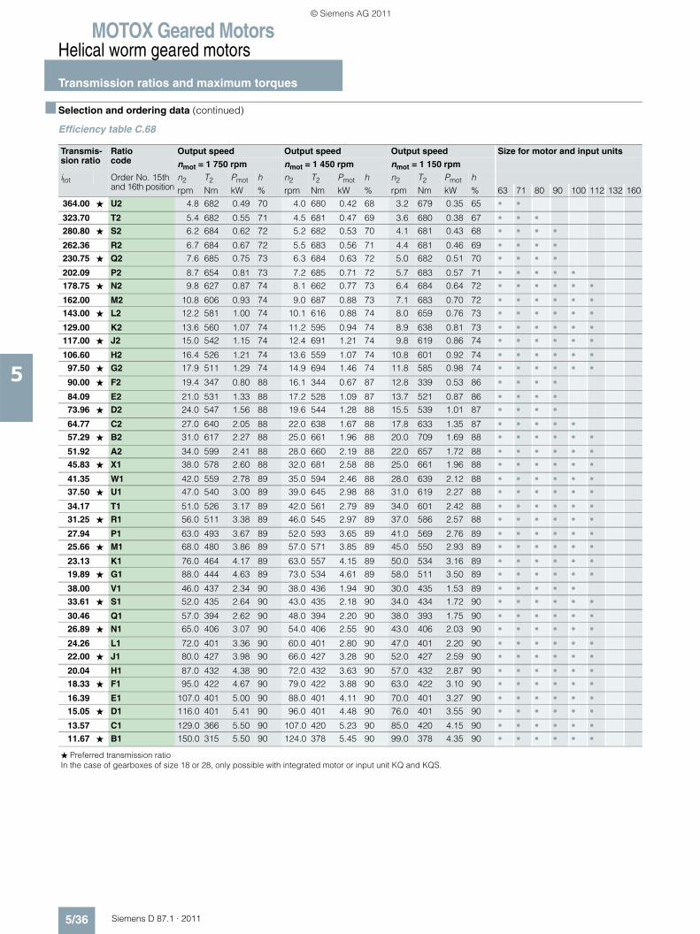
MOTOX Geared MotorsHelical worm geared motors
Transmission ratios and maximum torques
5/36 Siemens D 87.1 · 2011
5
■ Selection and ordering data (continued)
Efficiency table C.68
Transmis-sion ratio
Ratio code
Output speed Output speed Output speed Size for motor and input units
nmot = 1 750 rpm nmot = 1 450 rpm nmot = 1 150 rpm
itot Order No. 15th and 16th position
n2 T2 Pmot h n2 T2 Pmot h n2 T2 Pmot hrpm Nm kW % rpm Nm kW % rpm Nm kW % 63 71 80 90 100 112 132 160
364.00 ★ U2 4.8 682 0.49 70 4.0 680 0.42 68 3.2 679 0.35 65 • •
323.70 T2 5.4 682 0.55 71 4.5 681 0.47 69 3.6 680 0.38 67 • • •280.80 ★ S2 6.2 684 0.62 72 5.2 682 0.53 70 4.1 681 0.43 68 • • • •
262.36 R2 6.7 684 0.67 72 5.5 683 0.56 71 4.4 681 0.46 69 • • • •230.75 ★ Q2 7.6 685 0.75 73 6.3 684 0.63 72 5.0 682 0.51 70 • • • •
202.09 P2 8.7 654 0.81 73 7.2 685 0.71 72 5.7 683 0.57 71 • • • • •178.75 ★ N2 9.8 627 0.87 74 8.1 662 0.77 73 6.4 684 0.64 72 • • • • • •
162.00 M2 10.8 606 0.93 74 9.0 687 0.88 73 7.1 683 0.70 72 • • • • • •143.00 ★ L2 12.2 581 1.00 74 10.1 616 0.88 74 8.0 659 0.76 73 • • • • • •
129.00 K2 13.6 560 1.07 74 11.2 595 0.94 74 8.9 638 0.81 73 • • • • • •117.00 ★ J2 15.0 542 1.15 74 12.4 691 1.21 74 9.8 619 0.86 74 • • • • • •
106.60 H2 16.4 526 1.21 74 13.6 559 1.07 74 10.8 601 0.92 74 • • • • • •97.50 ★ G2 17.9 511 1.29 74 14.9 694 1.46 74 11.8 585 0.98 74 • • • • • •
90.00 ★ F2 19.4 347 0.80 88 16.1 344 0.67 87 12.8 339 0.53 86 • • • •
84.09 E2 21.0 531 1.33 88 17.2 528 1.09 87 13.7 521 0.87 86 • • • •73.96 ★ D2 24.0 547 1.56 88 19.6 544 1.28 88 15.5 539 1.01 87 • • • •
64.77 C2 27.0 640 2.05 88 22.0 638 1.67 88 17.8 633 1.35 87 • • • • •57.29 ★ B2 31.0 617 2.27 88 25.0 661 1.96 88 20.0 709 1.69 88 • • • • • •
51.92 A2 34.0 599 2.41 88 28.0 660 2.19 88 22.0 657 1.72 88 • • • • • •45.83 ★ X1 38.0 578 2.60 88 32.0 681 2.58 88 25.0 661 1.96 88 • • • • • •
41.35 W1 42.0 559 2.78 89 35.0 594 2.46 88 28.0 639 2.12 88 • • • • • •37.50 ★ U1 47.0 540 3.00 89 39.0 645 2.98 88 31.0 619 2.27 88 • • • • • •
34.17 T1 51.0 526 3.17 89 42.0 561 2.79 89 34.0 601 2.42 88 • • • • • •31.25 ★ R1 56.0 511 3.38 89 46.0 545 2.97 89 37.0 586 2.57 88 • • • • • •
27.94 P1 63.0 493 3.67 89 52.0 593 3.65 89 41.0 569 2.76 89 • • • • • •25.66 ★ M1 68.0 480 3.86 89 57.0 571 3.85 89 45.0 550 2.93 89 • • • • • •
23.13 K1 76.0 464 4.17 89 63.0 557 4.15 89 50.0 534 3.16 89 • • • • • •19.89 ★ G1 88.0 444 4.63 89 73.0 534 4.61 89 58.0 511 3.50 89 • • • • • •
38.00 V1 46.0 437 2.34 90 38.0 436 1.94 90 30.0 435 1.53 89 • • • • •33.61 ★ S1 52.0 435 2.64 90 43.0 435 2.18 90 34.0 434 1.72 90 • • • • • •
30.46 Q1 57.0 394 2.62 90 48.0 394 2.20 90 38.0 393 1.75 90 • • • • • •26.89 ★ N1 65.0 406 3.07 90 54.0 406 2.55 90 43.0 406 2.03 90 • • • • • •
24.26 L1 72.0 401 3.36 90 60.0 401 2.80 90 47.0 401 2.20 90 • • • • • •22.00 ★ J1 80.0 427 3.98 90 66.0 427 3.28 90 52.0 427 2.59 90 • • • • • •
20.04 H1 87.0 432 4.38 90 72.0 432 3.63 90 57.0 432 2.87 90 • • • • • •18.33 ★ F1 95.0 422 4.67 90 79.0 422 3.88 90 63.0 422 3.10 90 • • • • • •
16.39 E1 107.0 401 5.00 90 88.0 401 4.11 90 70.0 401 3.27 90 • • • • • •15.05 ★ D1 116.0 401 5.41 90 96.0 401 4.48 90 76.0 401 3.55 90 • • • • • •
13.57 C1 129.0 366 5.50 90 107.0 420 5.23 90 85.0 420 4.15 90 • • • • • •11.67 ★ B1 150.0 315 5.50 90 124.0 378 5.45 90 99.0 378 4.35 90 • • • • • •
� Preferred transmission ratioIn the case of gearboxes of size 18 or 28, only possible with integrated motor or input unit KQ and KQS.
© Siemens AG 2011
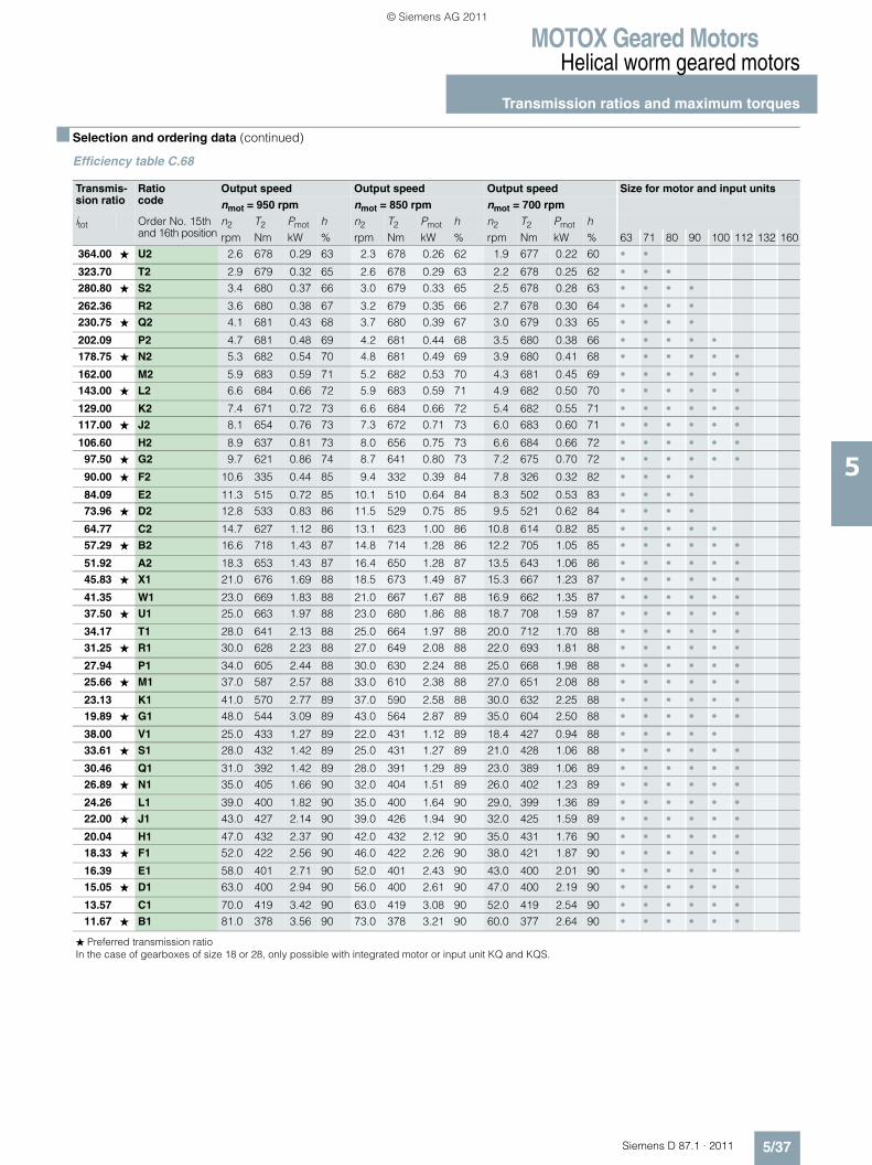
MOTOX Geared MotorsHelical worm geared motors
Transmission ratios and maximum torques
5/37Siemens D 87.1 · 2011
5
■ Selection and ordering data (continued)
Efficiency table C.68
Transmis-sion ratio
Ratio code
Output speed Output speed Output speed Size for motor and input units
nmot = 950 rpm nmot = 850 rpm nmot = 700 rpm
itot Order No. 15th and 16th position
n2 T2 Pmot h n2 T2 Pmot h n2 T2 Pmot hrpm Nm kW % rpm Nm kW % rpm Nm kW % 63 71 80 90 100 112 132 160
364.00 ★ U2 2.6 678 0.29 63 2.3 678 0.26 62 1.9 677 0.22 60 • •
323.70 T2 2.9 679 0.32 65 2.6 678 0.29 63 2.2 678 0.25 62 • • •280.80 ★ S2 3.4 680 0.37 66 3.0 679 0.33 65 2.5 678 0.28 63 • • • •
262.36 R2 3.6 680 0.38 67 3.2 679 0.35 66 2.7 678 0.30 64 • • • •230.75 ★ Q2 4.1 681 0.43 68 3.7 680 0.39 67 3.0 679 0.33 65 • • • •
202.09 P2 4.7 681 0.48 69 4.2 681 0.44 68 3.5 680 0.38 66 • • • • •178.75 ★ N2 5.3 682 0.54 70 4.8 681 0.49 69 3.9 680 0.41 68 • • • • • •
162.00 M2 5.9 683 0.59 71 5.2 682 0.53 70 4.3 681 0.45 69 • • • • • •143.00 ★ L2 6.6 684 0.66 72 5.9 683 0.59 71 4.9 682 0.50 70 • • • • • •
129.00 K2 7.4 671 0.72 73 6.6 684 0.66 72 5.4 682 0.55 71 • • • • • •117.00 ★ J2 8.1 654 0.76 73 7.3 672 0.71 73 6.0 683 0.60 71 • • • • • •
106.60 H2 8.9 637 0.81 73 8.0 656 0.75 73 6.6 684 0.66 72 • • • • • •97.50 ★ G2 9.7 621 0.86 74 8.7 641 0.80 73 7.2 675 0.70 72 • • • • • •
90.00 ★ F2 10.6 335 0.44 85 9.4 332 0.39 84 7.8 326 0.32 82 • • • •
84.09 E2 11.3 515 0.72 85 10.1 510 0.64 84 8.3 502 0.53 83 • • • •73.96 ★ D2 12.8 533 0.83 86 11.5 529 0.75 85 9.5 521 0.62 84 • • • •
64.77 C2 14.7 627 1.12 86 13.1 623 1.00 86 10.8 614 0.82 85 • • • • •57.29 ★ B2 16.6 718 1.43 87 14.8 714 1.28 86 12.2 705 1.05 85 • • • • • •
51.92 A2 18.3 653 1.43 87 16.4 650 1.28 87 13.5 643 1.06 86 • • • • • •45.83 ★ X1 21.0 676 1.69 88 18.5 673 1.49 87 15.3 667 1.23 87 • • • • • •
41.35 W1 23.0 669 1.83 88 21.0 667 1.67 88 16.9 662 1.35 87 • • • • • •37.50 ★ U1 25.0 663 1.97 88 23.0 680 1.86 88 18.7 708 1.59 87 • • • • • •
34.17 T1 28.0 641 2.13 88 25.0 664 1.97 88 20.0 712 1.70 88 • • • • • •31.25 ★ R1 30.0 628 2.23 88 27.0 649 2.08 88 22.0 693 1.81 88 • • • • • •
27.94 P1 34.0 605 2.44 88 30.0 630 2.24 88 25.0 668 1.98 88 • • • • • •25.66 ★ M1 37.0 587 2.57 88 33.0 610 2.38 88 27.0 651 2.08 88 • • • • • •
23.13 K1 41.0 570 2.77 89 37.0 590 2.58 88 30.0 632 2.25 88 • • • • • •19.89 ★ G1 48.0 544 3.09 89 43.0 564 2.87 89 35.0 604 2.50 88 • • • • • •
38.00 V1 25.0 433 1.27 89 22.0 431 1.12 89 18.4 427 0.94 88 • • • • •33.61 ★ S1 28.0 432 1.42 89 25.0 431 1.27 89 21.0 428 1.06 88 • • • • • •
30.46 Q1 31.0 392 1.42 89 28.0 391 1.29 89 23.0 389 1.06 89 • • • • • •26.89 ★ N1 35.0 405 1.66 90 32.0 404 1.51 89 26.0 402 1.23 89 • • • • • •
24.26 L1 39.0 400 1.82 90 35.0 400 1.64 90 29.0, 399 1.36 89 • • • • • •22.00 ★ J1 43.0 427 2.14 90 39.0 426 1.94 90 32.0 425 1.59 89 • • • • • •
20.04 H1 47.0 432 2.37 90 42.0 432 2.12 90 35.0 431 1.76 90 • • • • • •18.33 ★ F1 52.0 422 2.56 90 46.0 422 2.26 90 38.0 421 1.87 90 • • • • • •
16.39 E1 58.0 401 2.71 90 52.0 401 2.43 90 43.0 400 2.01 90 • • • • • •15.05 ★ D1 63.0 400 2.94 90 56.0 400 2.61 90 47.0 400 2.19 90 • • • • • •
13.57 C1 70.0 419 3.42 90 63.0 419 3.08 90 52.0 419 2.54 90 • • • • • •11.67 ★ B1 81.0 378 3.56 90 73.0 378 3.21 90 60.0 377 2.64 90 • • • • • •
� Preferred transmission ratioIn the case of gearboxes of size 18 or 28, only possible with integrated motor or input unit KQ and KQS.
© Siemens AG 2011
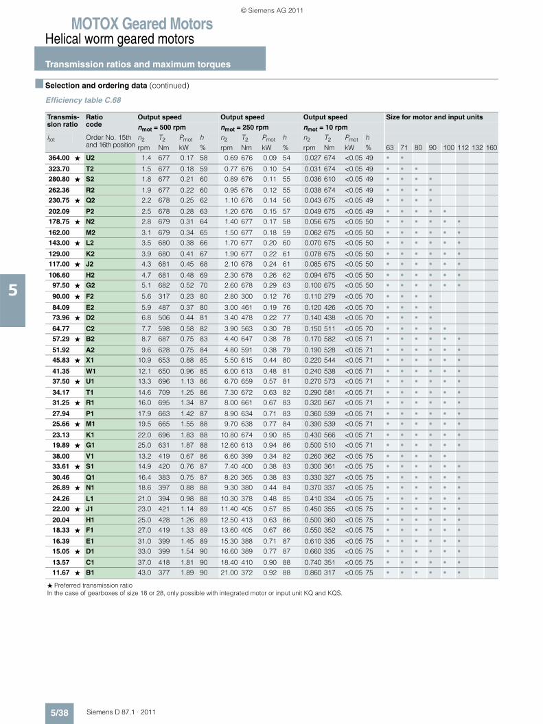
MOTOX Geared MotorsHelical worm geared motors
Transmission ratios and maximum torques
5/38 Siemens D 87.1 · 2011
5
■ Selection and ordering data (continued)
Efficiency table C.68
Transmis-sion ratio
Ratio code
Output speed Output speed Output speed Size for motor and input units
nmot = 500 rpm nmot = 250 rpm nmot = 10 rpm
itot Order No. 15th and 16th position
n2 T2 Pmot h n2 T2 Pmot h n2 T2 Pmot hrpm Nm kW % rpm Nm kW % rpm Nm kW % 63 71 80 90 100 112 132 160
364.00 ★ U2 1.4 677 0.17 58 0.69 676 0.09 54 0.027 674 <0.05 49 • •
323.70 T2 1.5 677 0.18 59 0.77 676 0.10 54 0.031 674 <0.05 49 • • •280.80 ★ S2 1.8 677 0.21 60 0.89 676 0.11 55 0.036 610 <0.05 49 • • • •
262.36 R2 1.9 677 0.22 60 0.95 676 0.12 55 0.038 674 <0.05 49 • • • •230.75 ★ Q2 2.2 678 0.25 62 1.10 676 0.14 56 0.043 675 <0.05 49 • • • •
202.09 P2 2.5 678 0.28 63 1.20 676 0.15 57 0.049 675 <0.05 49 • • • • •178.75 ★ N2 2.8 679 0.31 64 1.40 677 0.17 58 0.056 675 <0.05 50 • • • • • •
162.00 M2 3.1 679 0.34 65 1.50 677 0.18 59 0.062 675 <0.05 50 • • • • • •143.00 ★ L2 3.5 680 0.38 66 1.70 677 0.20 60 0.070 675 <0.05 50 • • • • • •
129.00 K2 3.9 680 0.41 67 1.90 677 0.22 61 0.078 675 <0.05 50 • • • • • •117.00 ★ J2 4.3 681 0.45 68 2.10 678 0.24 61 0.085 675 <0.05 50 • • • • • •
106.60 H2 4.7 681 0.48 69 2.30 678 0.26 62 0.094 675 <0.05 50 • • • • • •97.50 ★ G2 5.1 682 0.52 70 2.60 678 0.29 63 0.100 675 <0.05 50 • • • • • •
90.00 ★ F2 5.6 317 0.23 80 2.80 300 0.12 76 0.110 279 <0.05 70 • • • •
84.09 E2 5.9 487 0.37 80 3.00 461 0.19 76 0.120 426 <0.05 70 • • • •73.96 ★ D2 6.8 506 0.44 81 3.40 478 0.22 77 0.140 438 <0.05 70 • • • •
64.77 C2 7.7 598 0.58 82 3.90 563 0.30 78 0.150 511 <0.05 70 • • • • •57.29 ★ B2 8.7 687 0.75 83 4.40 647 0.38 78 0.170 582 <0.05 71 • • • • • •
51.92 A2 9.6 628 0.75 84 4.80 591 0.38 79 0.190 528 <0.05 71 • • • • • •45.83 ★ X1 10.9 653 0.88 85 5.50 615 0.44 80 0.220 544 <0.05 71 • • • • • •
41.35 W1 12.1 650 0.96 85 6.00 613 0.48 81 0.240 538 <0.05 71 • • • • • •37.50 ★ U1 13.3 696 1.13 86 6.70 659 0.57 81 0.270 573 <0.05 71 • • • • • •
34.17 T1 14.6 709 1.25 86 7.30 672 0.63 82 0.290 581 <0.05 71 • • • • • •31.25 ★ R1 16.0 695 1.34 87 8.00 661 0.67 83 0.320 567 <0.05 71 • • • • • •
27.94 P1 17.9 663 1.42 87 8.90 634 0.71 83 0.360 539 <0.05 71 • • • • • •25.66 ★ M1 19.5 665 1.55 88 9.70 638 0.77 84 0.390 539 <0.05 71 • • • • • •
23.13 K1 22.0 696 1.83 88 10.80 674 0.90 85 0.430 566 <0.05 71 • • • • • •19.89 ★ G1 25.0 631 1.87 88 12.60 613 0.94 86 0.500 510 <0.05 71 • • • • • •
38.00 V1 13.2 419 0.67 86 6.60 399 0.34 82 0.260 362 <0.05 75 • • • • •33.61 ★ S1 14.9 420 0.76 87 7.40 400 0.38 83 0.300 361 <0.05 75 • • • • • •
30.46 Q1 16.4 383 0.75 87 8.20 365 0.38 83 0.330 327 <0.05 75 • • • • • •26.89 ★ N1 18.6 397 0.88 88 9.30 380 0.44 84 0.370 337 <0.05 75 • • • • • •
24.26 L1 21.0 394 0.98 88 10.30 378 0.48 85 0.410 334 <0.05 75 • • • • • •22.00 ★ J1 23.0 421 1.14 89 11.40 405 0.57 85 0.450 355 <0.05 75 • • • • • •
20.04 H1 25.0 428 1.26 89 12.50 413 0.63 86 0.500 360 <0.05 75 • • • • • •18.33 ★ F1 27.0 419 1.33 89 13.60 405 0.67 86 0.550 352 <0.05 75 • • • • • •
16.39 E1 31.0 399 1.45 89 15.30 388 0.71 87 0.610 335 <0.05 75 • • • • • •15.05 ★ D1 33.0 399 1.54 90 16.60 389 0.77 87 0.660 335 <0.05 75 • • • • • •
13.57 C1 37.0 418 1.81 90 18.40 410 0.90 88 0.740 351 <0.05 75 • • • • • •11.67 ★ B1 43.0 377 1.89 90 21.00 372 0.92 88 0.860 317 <0.05 75 • • • • • •
� Preferred transmission ratioIn the case of gearboxes of size 18 or 28, only possible with integrated motor or input unit KQ and KQS.
© Siemens AG 2011
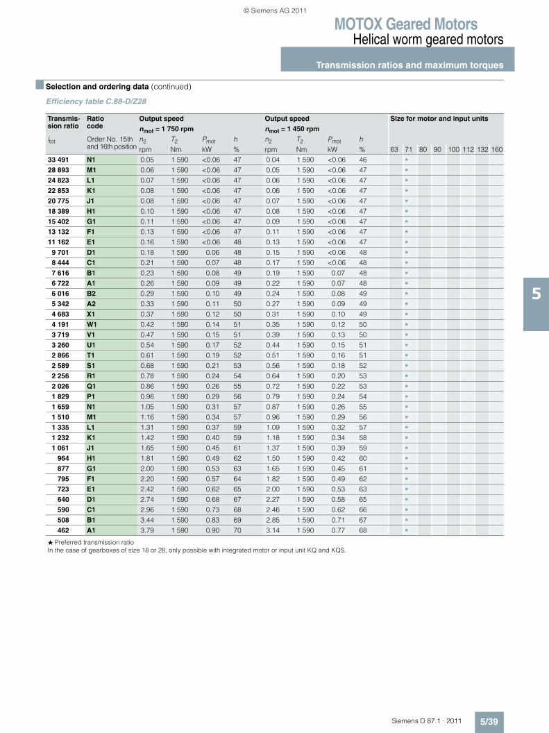
MOTOX Geared MotorsHelical worm geared motors
Transmission ratios and maximum torques
5/39Siemens D 87.1 · 2011
5
■ Selection and ordering data (continued)
Efficiency table C.88-D/Z28
Transmis-sion ratio
Ratio code
Output speed Output speed Size for motor and input units
nmot = 1 750 rpm nmot = 1 450 rpm
itot Order No. 15th and 16th position
n2 T2 Pmot h n2 T2 Pmot hrpm Nm kW % rpm Nm kW % 63 71 80 90 100 112 132 160
33 491 N1 0.05 1 590 <0.06 47 0.04 1 590 <0.06 46 •28 893 M1 0.06 1 590 <0.06 47 0.05 1 590 <0.06 47 •24 823 L1 0.07 1 590 <0.06 47 0.06 1 590 <0.06 47 •22 853 K1 0.08 1 590 <0.06 47 0.06 1 590 <0.06 47 •20 775 J1 0.08 1 590 <0.06 47 0.07 1 590 <0.06 47 •18 389 H1 0.10 1 590 <0.06 47 0.08 1 590 <0.06 47 •15 402 G1 0.11 1 590 <0.06 47 0.09 1 590 <0.06 47 •13 132 F1 0.13 1 590 <0.06 47 0.11 1 590 <0.06 47 •11 162 E1 0.16 1 590 <0.06 48 0.13 1 590 <0.06 47 •
9 701 D1 0.18 1 590 0.06 48 0.15 1 590 <0.06 48 •8 444 C1 0.21 1 590 0.07 48 0.17 1 590 <0.06 48 •7 616 B1 0.23 1 590 0.08 49 0.19 1 590 0.07 48 •6 722 A1 0.26 1 590 0.09 49 0.22 1 590 0.07 48 •6 016 B2 0.29 1 590 0.10 49 0.24 1 590 0.08 49 •5 342 A2 0.33 1 590 0.11 50 0.27 1 590 0.09 49 •4 683 X1 0.37 1 590 0.12 50 0.31 1 590 0.10 49 •4 191 W1 0.42 1 590 0.14 51 0.35 1 590 0.12 50 •3 719 V1 0.47 1 590 0.15 51 0.39 1 590 0.13 50 •3 260 U1 0.54 1 590 0.17 52 0.44 1 590 0.15 51 •2 866 T1 0.61 1 590 0.19 52 0.51 1 590 0.16 51 •2 589 S1 0.68 1 590 0.21 53 0.56 1 590 0.18 52 •2 256 R1 0.78 1 590 0.24 54 0.64 1 590 0.20 53 •2 026 Q1 0.86 1 590 0.26 55 0.72 1 590 0.22 53 •1 829 P1 0.96 1 590 0.29 56 0.79 1 590 0.24 54 •1 659 N1 1.05 1 590 0.31 57 0.87 1 590 0.26 55 •1 510 M1 1.16 1 590 0.34 57 0.96 1 590 0.29 56 •1 335 L1 1.31 1 590 0.37 59 1.09 1 590 0.32 57 •1 232 K1 1.42 1 590 0.40 59 1.18 1 590 0.34 58 •1 061 J1 1.65 1 590 0.45 61 1.37 1 590 0.39 59 •
964 H1 1.81 1 590 0.49 62 1.50 1 590 0.42 60 •877 G1 2.00 1 590 0.53 63 1.65 1 590 0.45 61 •795 F1 2.20 1 590 0.57 64 1.82 1 590 0.49 62 •723 E1 2.42 1 590 0.62 65 2.00 1 590 0.53 63 •640 D1 2.74 1 590 0.68 67 2.27 1 590 0.58 65 •590 C1 2.96 1 590 0.73 68 2.46 1 590 0.62 66 •508 B1 3.44 1 590 0.83 69 2.85 1 590 0.71 67 •462 A1 3.79 1 590 0.90 70 3.14 1 590 0.77 68 •
� Preferred transmission ratioIn the case of gearboxes of size 18 or 28, only possible with integrated motor or input unit KQ and KQS.
© Siemens AG 2011
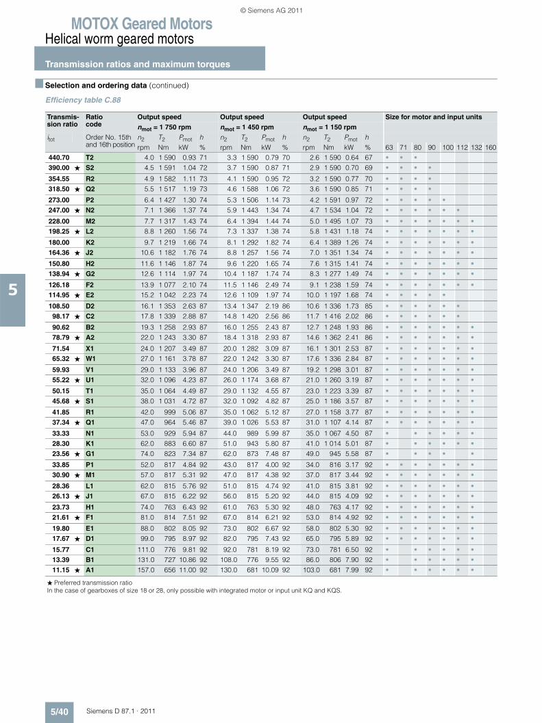
MOTOX Geared MotorsHelical worm geared motors
Transmission ratios and maximum torques
5/40 Siemens D 87.1 · 2011
5
■ Selection and ordering data (continued)
Efficiency table C.88
Transmis-sion ratio
Ratio code
Output speed Output speed Output speed Size for motor and input units
nmot = 1 750 rpm nmot = 1 450 rpm nmot = 1 150 rpm
itot Order No. 15th and 16th position
n2 T2 Pmot h n2 T2 Pmot h n2 T2 Pmot hrpm Nm kW % rpm Nm kW % rpm Nm kW % 63 71 80 90 100 112 132 160
440.70 T2 4.0 1 590 0.93 71 3.3 1 590 0.79 70 2.6 1 590 0.64 67 • • •390.00 ★ S2 4.5 1 591 1.04 72 3.7 1 590 0.87 71 2.9 1 590 0.70 69 • • • •
354.55 R2 4.9 1 582 1.11 73 4.1 1 590 0.95 72 3.2 1 590 0.77 70 • • • •318.50 ★ Q2 5.5 1 517 1.19 73 4.6 1 588 1.06 72 3.6 1 590 0.85 71 • • • •
273.00 P2 6.4 1 427 1.30 74 5.3 1 506 1.14 73 4.2 1 591 0.97 72 • • • • •247.00 ★ N2 7.1 1 366 1.37 74 5.9 1 443 1.34 74 4.7 1 534 1.04 72 • • • • • •
228.00 M2 7.7 1 317 1.43 74 6.4 1 394 1.44 74 5.0 1 495 1.07 73 • • • • • • •198.25 ★ L2 8.8 1 260 1.56 74 7.3 1 337 1.38 74 5.8 1 431 1.18 74 • • • • • • •
180.00 K2 9.7 1 219 1.66 74 8.1 1 292 1.82 74 6.4 1 389 1.26 74 • • • • • • •164.36 ★ J2 10.6 1 182 1.76 74 8.8 1 257 1.56 74 7.0 1 351 1.34 74 • • • • • • •
150.80 H2 11.6 1 146 1.87 74 9.6 1 220 1.65 74 7.6 1 315 1.41 74 • • • • • • •138.94 ★ G2 12.6 1 114 1.97 74 10.4 1 187 1.74 74 8.3 1 277 1.49 74 • • • • • • •
126.18 F2 13.9 1 077 2.10 74 11.5 1 146 2.49 74 9.1 1 238 1.59 74 • • • • • • •114.95 ★ E2 15.2 1 042 2.23 74 12.6 1 109 1.97 74 10.0 1 197 1.68 74 • • • • •
108.50 D2 16.1 1 353 2.63 87 13.4 1 347 2.19 86 10.6 1 336 1.73 85 • • • • • •98.17 ★ C2 17.8 1 339 2.88 87 14.8 1 420 2.56 86 11.7 1 416 2.02 86 • • • • • •
90.62 B2 19.3 1 258 2.93 87 16.0 1 255 2.43 87 12.7 1 248 1.93 86 • • • • • • •78.79 ★ A2 22.0 1 243 3.30 87 18.4 1 318 2.93 87 14.6 1 362 2.41 86 • • • • • • •
71.54 X1 24.0 1 207 3.49 87 20.0 1 282 3.09 87 16.1 1 301 2.53 87 • • • • • • •65.32 ★ W1 27.0 1 161 3.78 87 22.0 1 242 3.30 87 17.6 1 336 2.84 87 • • • • • • •
59.93 V1 29.0 1 133 3.96 87 24.0 1 206 3.49 87 19.2 1 298 3.01 87 • • • • • • •55.22 ★ U1 32.0 1 096 4.23 87 26.0 1 174 3.68 87 21.0 1 260 3.19 87 • • • • • • •
50.15 T1 35.0 1 064 4.49 87 29.0 1 132 4.55 87 23.0 1 223 3.39 87 • • • • • • •45.68 ★ S1 38.0 1 031 4.72 87 32.0 1 092 4.82 87 25.0 1 186 3.57 87 • • • • • • •
41.85 R1 42.0 999 5.06 87 35.0 1 062 5.12 87 27.0 1 158 3.77 87 • • • • • • •37.34 ★ Q1 47.0 964 5.46 87 39.0 1 026 5.53 87 31.0 1 107 4.14 87 • • • • • • •
33.33 N1 53.0 929 5.94 87 44.0 989 5.99 87 35.0 1 067 4.50 87 • • • • • •28.30 K1 62.0 883 6.60 87 51.0 943 5.80 87 41.0 1 014 5.01 87 • • • • • •23.56 ★ G1 74.0 823 7.34 87 62.0 873 7.48 87 49.0 945 5.58 87 • • • • •
33.85 P1 52.0 817 4.84 92 43.0 817 4.00 92 34.0 816 3.17 92 • • • • • • •30.90 ★ M1 57.0 817 5.31 92 47.0 817 4.38 92 37.0 817 3.44 92 • • • • • • •
28.36 L1 62.0 815 5.76 92 51.0 815 4.74 92 41.0 815 3.81 92 • • • • • • •26.13 ★ J1 67.0 815 6.22 92 56.0 815 5.20 92 44.0 815 4.09 92 • • • • • • •
23.73 H1 74.0 763 6.43 92 61.0 763 5.30 92 48.0 763 4.17 92 • • • • • • •21.61 ★ F1 81.0 814 7.51 92 67.0 814 6.21 92 53.0 814 4.92 92 • • • • • • •
19.80 E1 88.0 802 8.05 92 73.0 802 6.67 92 58.0 802 5.30 92 • • • • • • •17.67 ★ D1 99.0 795 8.97 92 82.0 795 7.43 92 65.0 795 5.89 92 • • • • • • •
15.77 C1 111.0 776 9.81 92 92.0 781 8.19 92 73.0 781 6.50 92 • • • • • •13.39 B1 131.0 727 10.86 92 108.0 776 9.55 92 86.0 806 7.90 92 • • • • • •11.15 ★ A1 157.0 656 11.00 92 130.0 681 10.09 92 103.0 681 7.99 92 • • • • • •
� Preferred transmission ratioIn the case of gearboxes of size 18 or 28, only possible with integrated motor or input unit KQ and KQS.
© Siemens AG 2011
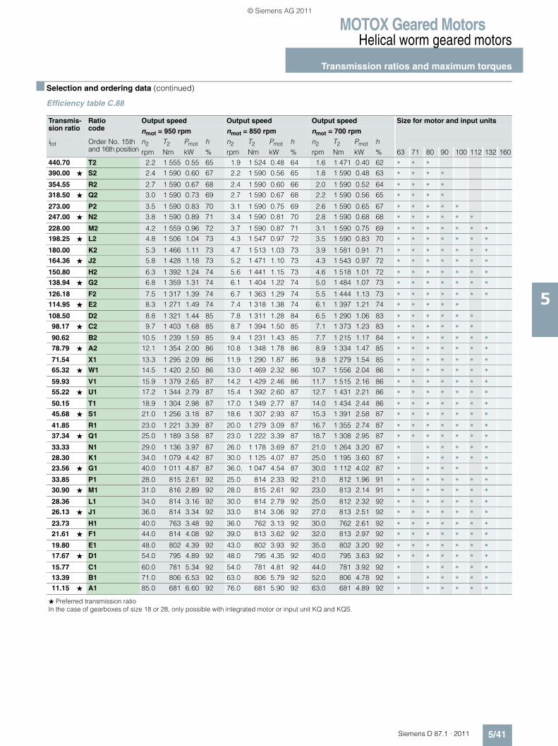
MOTOX Geared MotorsHelical worm geared motors
Transmission ratios and maximum torques
5/41Siemens D 87.1 · 2011
5
■ Selection and ordering data (continued)
Efficiency table C.88
Transmis-sion ratio
Ratio code
Output speed Output speed Output speed Size for motor and input units
nmot = 950 rpm nmot = 850 rpm nmot = 700 rpm
itot Order No. 15th and 16th position
n2 T2 Pmot h n2 T2 Pmot h n2 T2 Pmot hrpm Nm kW % rpm Nm kW % rpm Nm kW % 63 71 80 90 100 112 132 160
440.70 T2 2.2 1 555 0.55 65 1.9 1 524 0.48 64 1.6 1 471 0.40 62 • • •390.00 ★ S2 2.4 1 590 0.60 67 2.2 1 590 0.56 65 1.8 1 590 0.48 63 • • • •
354.55 R2 2.7 1 590 0.67 68 2.4 1 590 0.60 66 2.0 1 590 0.52 64 • • • •318.50 ★ Q2 3.0 1 590 0.73 69 2.7 1 590 0.67 68 2.2 1 590 0.56 65 • • • •
273.00 P2 3.5 1 590 0.83 70 3.1 1 590 0.75 69 2.6 1 590 0.65 67 • • • • •247.00 ★ N2 3.8 1 590 0.89 71 3.4 1 590 0.81 70 2.8 1 590 0.68 68 • • • • • •
228.00 M2 4.2 1 559 0.96 72 3.7 1 590 0.87 71 3.1 1 590 0.75 69 • • • • • • •198.25 ★ L2 4.8 1 506 1.04 73 4.3 1 547 0.97 72 3.5 1 590 0.83 70 • • • • • • •
180.00 K2 5.3 1 466 1.11 73 4.7 1 513 1.03 73 3.9 1 581 0.91 71 • • • • • • •164.36 ★ J2 5.8 1 428 1.18 73 5.2 1 471 1.10 73 4.3 1 543 0.97 72 • • • • • • •
150.80 H2 6.3 1 392 1.24 74 5.6 1 441 1.15 73 4.6 1 518 1.01 72 • • • • • • •138.94 ★ G2 6.8 1 359 1.31 74 6.1 1 404 1.22 74 5.0 1 484 1.07 73 • • • • • • •
126.18 F2 7.5 1 317 1.39 74 6.7 1 363 1.29 74 5.5 1 444 1.13 73 • • • • • • •114.95 ★ E2 8.3 1 271 1.49 74 7.4 1 318 1.38 74 6.1 1 397 1.21 74 • • • • •
108.50 D2 8.8 1 321 1.44 85 7.8 1 311 1.28 84 6.5 1 290 1.06 83 • • • • • •98.17 ★ C2 9.7 1 403 1.68 85 8.7 1 394 1.50 85 7.1 1 373 1.23 83 • • • • • •
90.62 B2 10.5 1 239 1.59 85 9.4 1 231 1.43 85 7.7 1 215 1.17 84 • • • • • • •78.79 ★ A2 12.1 1 354 2.00 86 10.8 1 348 1.78 86 8.9 1 334 1.47 85 • • • • • • •
71.54 X1 13.3 1 295 2.09 86 11.9 1 290 1.87 86 9.8 1 279 1.54 85 • • • • • • •65.32 ★ W1 14.5 1 420 2.50 86 13.0 1 469 2.32 86 10.7 1 556 2.04 86 • • • • • • •
59.93 V1 15.9 1 379 2.65 87 14.2 1 429 2.46 86 11.7 1 515 2.16 86 • • • • • • •55.22 ★ U1 17.2 1 344 2.79 87 15.4 1 392 2.60 87 12.7 1 431 2.21 86 • • • • • • •
50.15 T1 18.9 1 304 2.98 87 17.0 1 349 2.77 87 14.0 1 434 2.44 86 • • • • • • •45.68 ★ S1 21.0 1 256 3.18 87 18.6 1 307 2.93 87 15.3 1 391 2.58 87 • • • • • • •
41.85 R1 23.0 1 221 3.39 87 20.0 1 279 3.09 87 16.7 1 355 2.74 87 • • • • • • •37.34 ★ Q1 25.0 1 189 3.58 87 23.0 1 222 3.39 87 18.7 1 308 2.95 87 • • • • • • •
33.33 N1 29.0 1 136 3.97 87 26.0 1 178 3.69 87 21.0 1 264 3.20 87 • • • • • •28.30 K1 34.0 1 079 4.42 87 30.0 1 125 4.07 87 25.0 1 195 3.60 87 • • • • • •23.56 ★ G1 40.0 1 011 4.87 87 36.0, 1 047 4.54 87 30.0 1 112 4.02 87 • • • • •
33.85 P1 28.0 815 2.61 92 25.0 814 2.33 92 21.0 812 1.96 91 • • • • • • •30.90 ★ M1 31.0 816 2.89 92 28.0 815 2.61 92 23.0 813 2.14 91 • • • • • • •
28.36 L1 34.0 814 3.16 92 30.0 814 2.79 92 25.0 812 2.32 92 • • • • • • •26.13 ★ J1 36.0 814 3.34 92 33.0 814 3.06 92 27.0 813 2.51 92 • • • • • • •
23.73 H1 40.0 763 3.48 92 36.0 762 3.13 92 30.0 762 2.61 92 • • • • • • •21.61 ★ F1 44.0 814 4.08 92 39.0 813 3.62 92 32.0 813 2.97 92 • • • • • • •
19.80 E1 48.0 802 4.39 92 43.0 802 3.93 92 35.0 802 3.20 92 • • • • • • •17.67 ★ D1 54.0 795 4.89 92 48.0 795 4.35 92 40.0 795 3.63 92 • • • • • • •
15.77 C1 60.0 781 5.34 92 54.0 781 4.81 92 44.0 781 3.92 92 • • • • • •13.39 B1 71.0 806 6.53 92 63.0 806 5.79 92 52.0 806 4.78 92 • • • • • •11.15 ★ A1 85.0 681 6.60 92 76.0 681 5.90 92 63.0 681 4.89 92 • • • • • •
� Preferred transmission ratioIn the case of gearboxes of size 18 or 28, only possible with integrated motor or input unit KQ and KQS.
© Siemens AG 2011
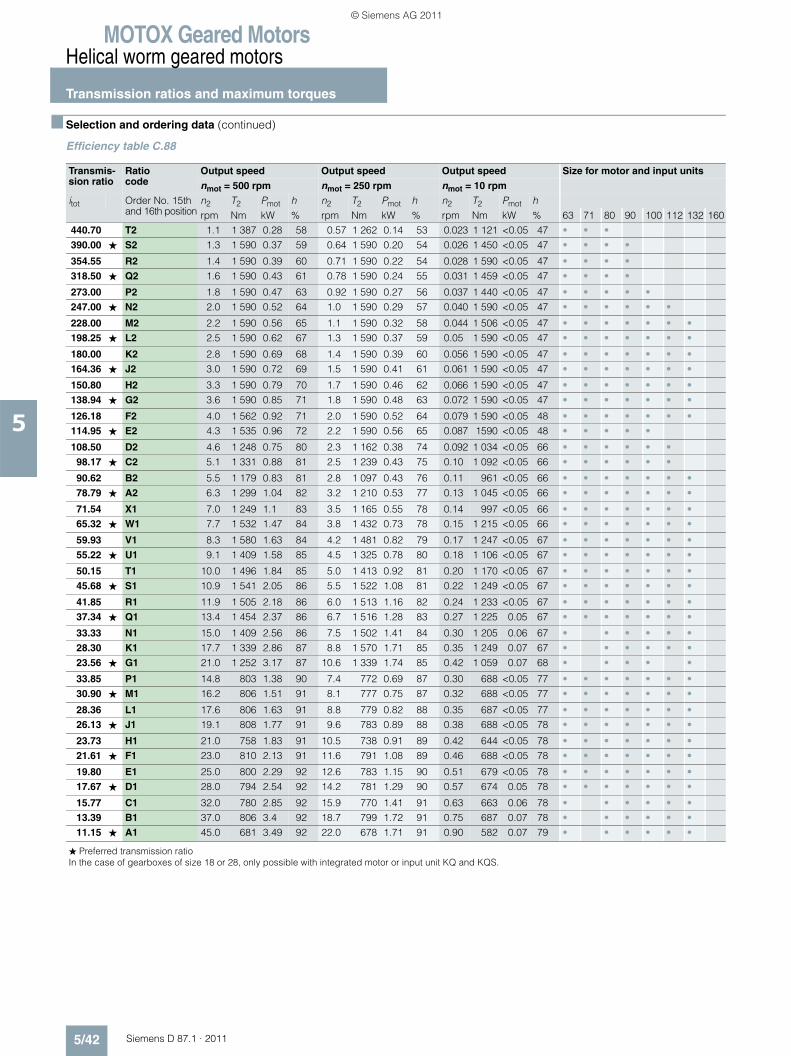
MOTOX Geared MotorsHelical worm geared motors
Transmission ratios and maximum torques
5/42 Siemens D 87.1 · 2011
5
■ Selection and ordering data (continued)
Efficiency table C.88
Transmis-sion ratio
Ratio code
Output speed Output speed Output speed Size for motor and input units
nmot = 500 rpm nmot = 250 rpm nmot = 10 rpm
itot Order No. 15th and 16th position
n2 T2 Pmot h n2 T2 Pmot h n2 T2 Pmot hrpm Nm kW % rpm Nm kW % rpm Nm kW % 63 71 80 90 100 112 132 160
440.70 T2 1.1 1 387 0.28 58 0.57 1 262 0.14 53 0.023 1 121 <0.05 47 • • •390.00 ★ S2 1.3 1 590 0.37 59 0.64 1 590 0.20 54 0.026 1 450 <0.05 47 • • • •
354.55 R2 1.4 1 590 0.39 60 0.71 1 590 0.22 54 0.028 1 590 <0.05 47 • • • •318.50 ★ Q2 1.6 1 590 0.43 61 0.78 1 590 0.24 55 0.031 1 459 <0.05 47 • • • •
273.00 P2 1.8 1 590 0.47 63 0.92 1 590 0.27 56 0.037 1 440 <0.05 47 • • • • •247.00 ★ N2 2.0 1 590 0.52 64 1.0 1 590 0.29 57 0.040 1 590 <0.05 47 • • • • • •
228.00 M2 2.2 1 590 0.56 65 1.1 1 590 0.32 58 0.044 1 506 <0.05 47 • • • • • • •198.25 ★ L2 2.5 1 590 0.62 67 1.3 1 590 0.37 59 0.05 1 590 <0.05 47 • • • • • • •
180.00 K2 2.8 1 590 0.69 68 1.4 1 590 0.39 60 0.056 1 590 <0.05 47 • • • • • • •164.36 ★ J2 3.0 1 590 0.72 69 1.5 1 590 0.41 61 0.061 1 590 <0.05 47 • • • • • • •
150.80 H2 3.3 1 590 0.79 70 1.7 1 590 0.46 62 0.066 1 590 <0.05 47 • • • • • • •138.94 ★ G2 3.6 1 590 0.85 71 1.8 1 590 0.48 63 0.072 1 590 <0.05 47 • • • • • • •
126.18 F2 4.0 1 562 0.92 71 2.0 1 590 0.52 64 0.079 1 590 <0.05 48 • • • • • • •114.95 ★ E2 4.3 1 535 0.96 72 2.2 1 590 0.56 65 0.087 1590 <0.05 48 • • • • •
108.50 D2 4.6 1 248 0.75 80 2.3 1 162 0.38 74 0.092 1 034 <0.05 66 • • • • • •98.17 ★ C2 5.1 1 331 0.88 81 2.5 1 239 0.43 75 0.10 1 092 <0.05 66 • • • • • •
90.62 B2 5.5 1 179 0.83 81 2.8 1 097 0.43 76 0.11 961 <0.05 66 • • • • • • •78.79 ★ A2 6.3 1 299 1.04 82 3.2 1 210 0.53 77 0.13 1 045 <0.05 66 • • • • • • •
71.54 X1 7.0 1 249 1.1 83 3.5 1 165 0.55 78 0.14 997 <0.05 66 • • • • • • •65.32 ★ W1 7.7 1 532 1.47 84 3.8 1 432 0.73 78 0.15 1 215 <0.05 66 • • • • • • •
59.93 V1 8.3 1 580 1.63 84 4.2 1 481 0.82 79 0.17 1 247 <0.05 67 • • • • • • •55.22 ★ U1 9.1 1 409 1.58 85 4.5 1 325 0.78 80 0.18 1 106 <0.05 67 • • • • • • •
50.15 T1 10.0 1 496 1.84 85 5.0 1 413 0.92 81 0.20 1 170 <0.05 67 • • • • • • •45.68 ★ S1 10.9 1 541 2.05 86 5.5 1 522 1.08 81 0.22 1 249 <0.05 67 • • • • • • •
41.85 R1 11.9 1 505 2.18 86 6.0 1 513 1.16 82 0.24 1 233 <0.05 67 • • • • • • •37.34 ★ Q1 13.4 1 454 2.37 86 6.7 1 516 1.28 83 0.27 1 225 0.05 67 • • • • • • •
33.33 N1 15.0 1 409 2.56 86 7.5 1 502 1.41 84 0.30 1 205 0.06 67 • • • • • •28.30 K1 17.7 1 339 2.86 87 8.8 1 570 1.71 85 0.35 1 249 0.07 67 • • • • • •23.56 ★ G1 21.0 1 252 3.17 87 10.6 1 339 1.74 85 0.42 1 059 0.07 68 • • • • •
33.85 P1 14.8 803 1.38 90 7.4 772 0.69 87 0.30 688 <0.05 77 • • • • • • •30.90 ★ M1 16.2 806 1.51 91 8.1 777 0.75 87 0.32 688 <0.05 77 • • • • • • •
28.36 L1 17.6 806 1.63 91 8.8 779 0.82 88 0.35 687 <0.05 77 • • • • • • •26.13 ★ J1 19.1 808 1.77 91 9.6 783 0.89 88 0.38 688 <0.05 78 • • • • • • •
23.73 H1 21.0 758 1.83 91 10.5 738 0.91 89 0.42 644 <0.05 78 • • • • • • •21.61 ★ F1 23.0 810 2.13 91 11.6 791 1.08 89 0.46 688 <0.05 78 • • • • • • •
19.80 E1 25.0 800 2.29 92 12.6 783 1.15 90 0.51 679 <0.05 78 • • • • • • •17.67 ★ D1 28.0 794 2.54 92 14.2 781 1.29 90 0.57 674 0.05 78 • • • • • • •
15.77 C1 32.0 780 2.85 92 15.9 770 1.41 91 0.63 663 0.06 78 • • • • • •13.39 B1 37.0 806 3.4 92 18.7 799 1.72 91 0.75 687 0.07 78 • • • • • •11.15 ★ A1 45.0 681 3.49 92 22.0 678 1.71 91 0.90 582 0.07 79 • • • • • •
� Preferred transmission ratioIn the case of gearboxes of size 18 or 28, only possible with integrated motor or input unit KQ and KQS.
© Siemens AG 2011
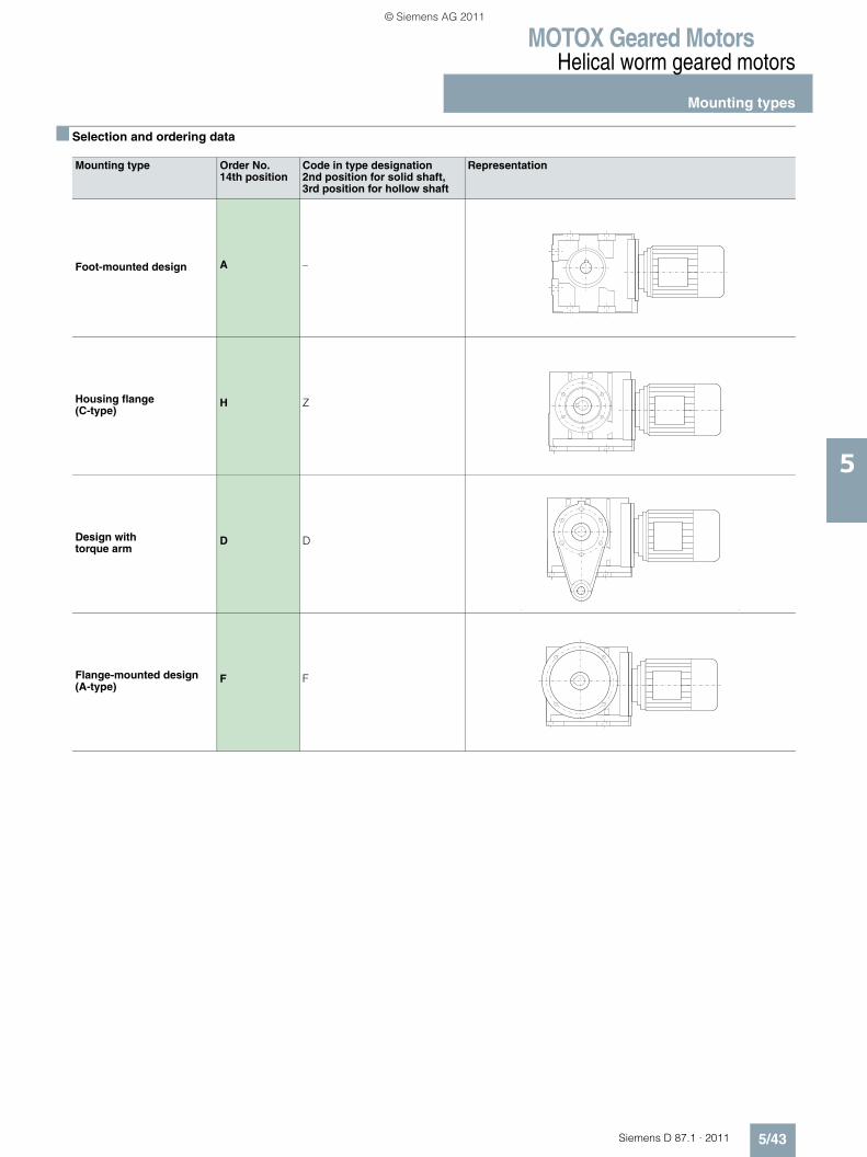
MOTOX Geared MotorsHelical worm geared motors
Mounting types
5/43Siemens D 87.1 · 2011
5
■ Selection and ordering data
Mounting type Order No. 14th position
Code in type designation2nd position for solid shaft, 3rd position for hollow shaft
Representation
Foot-mounted design A –
Housing flange (C-type)
H Z
Design with torque arm
D D
Flange-mounted design (A-type)
F F
© Siemens AG 2011
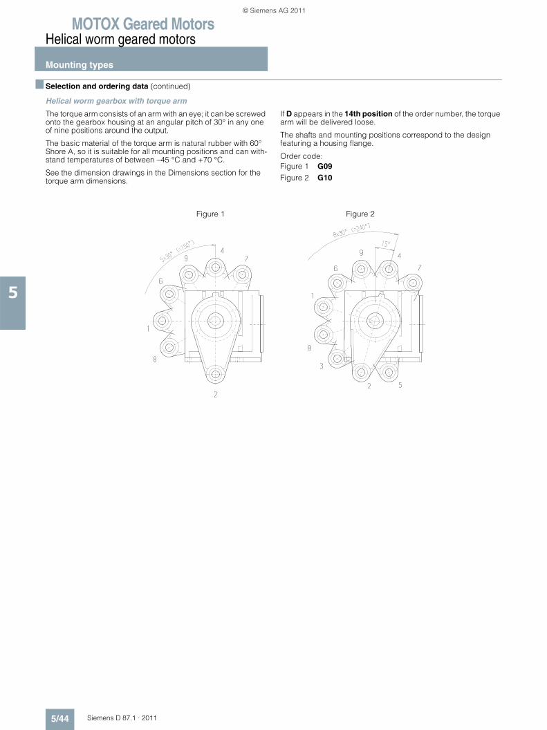
MOTOX Geared MotorsHelical worm geared motors
Mounting types
5/44 Siemens D 87.1 · 2011
5
■ Selection and ordering data (continued)
Helical worm gearbox with torque arm
The torque arm consists of an arm with an eye; it can be screwed onto the gearbox housing at an angular pitch of 30° in any one of nine positions around the output.
The basic material of the torque arm is natural rubber with 60° Shore A, so it is suitable for all mounting positions and can with-stand temperatures of between –45 °C and +70 °C.
See the dimension drawings in the Dimensions section for the torque arm dimensions.
If D appears in the 14th position of the order number, the torque arm will be delivered loose.
The shafts and mounting positions correspond to the design featuring a housing flange.
Order code:Figure 1 G09Figure 2 G10
Figure 1 Figure 2
© Siemens AG 2011
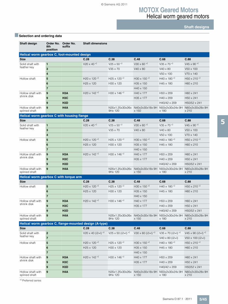
MOTOX Geared MotorsHelical worm geared motors
Shaft designs
5/45Siemens D 87.1 · 2011
5
■ Selection and ordering data
Shaft design Order No.8th position
Order No. suffix
Shaft dimensions
Helical worm gearbox C, foot-mounted designSize C.28 C.38 C.48 C.68 C.88
Solid shaft with feather key
1 V20 x 40 *) V25 x 50 *) V30 x 60 *) V35 x 70 *) V45 x 90 *)
3 V35 x 70 V40 x 80 V40 x 80 V50 x 100
4 V50 x 100 V70 x 140
Hollow shaft 5 H20 x 120 *) H25 x 120 *) H30 x 150 *) H40 x 180 *) H50 x 210 *)
6 H25 x 120 H30 x 120 H35 x 150 H45 x 180 H60 x 210
7 H40 x 150
Hollow shaft with shrink disk
9 H3A H20 x 142 *) H30 x 146 *) H40 x 177 H50 x 209 H60 x 241
9 H3C H35 x 177 H40 x 209 H50 x 241
9 H3D H40/42 x 209 H50/52 x 241
Hollow shaft with splined shaft
9 H4A N35x1.25x30x26x 9Hx 120
N40x2x30x18x 9H x 150
N50x2x30x24x 9H x 180
N60x2x30x28x 9H x 210
Helical worm gearbox C with housing flangeSize C.28 C.38 C.48 C.68 C.88
Solid shaft with feather key
1 V20 x 40 *) V25 x 50 *) V30 x 60 *) V35 x 70 *) V45 x 90 *)
3 V35 x 70 V40 x 80 V40 x 80 V50 x 100
4 V50 x 100 V70 x 140
Hollow shaft 5 H20 x 120 *) H25 x 120 *) H30 x 150 *) H40 x 180 *) H50 x 210 *)
6 H25 x 120 H30 x 120 H35 x 150 H45 x 180 H60 x 210
7 H40 x 150
Hollow shaft with shrink disk
9 H3A H20 x 142 *) H30 x 146 *) H40 x 177 H50 x 209 H60 x 241
9 H3C H35 x 177 H40 x 209 H50 x 241
9 H3D H40/42 x 209 H50/52 x 241
Hollow shaft with splined shaft
9 H4A N35x1.25x30x26x 9Hx 120
N40x2x30x18x 9H x 150
N50x2x30x24x 9H x 180
N60x2x30x28x 9H x 210
Helical worm gearbox C with torque armSize C.28 C.38 C.48 C.68 C.88
Hollow shaft 5 H20 x 120 *) H25 x 120 *) H30 x 150 *) H40 x 180 *) H50 x 210 *)
6 H25 x 120 H30 x 120 H35 x 150 H45 x 180 H60 x 210
7 H40 x 150
Hollow shaft with shrink disk
9 H3A H20 x 142 *) H30 x 146 *) H40 x 177 H50 x 209 H60 x 241
9 H3C H35 x 177 H40 x 209 H50 x 241
9 H3D H40/42 x 209 H50/52 x 241
Hollow shaft with splined shaft
9 H4A N35x1.25x30x26x 9Hx 120
N40x2x30x18x 9H x 150
N50x2x30x24x 9H x 180
N60x2x30x28x 9H x 210
Helical worm gearbox C, flange-mounted design (A-type) Size C.28 C.38 C.48 C.68 C.88
Solid shaft with feather key
2 V20 x 40 (i2=l) *) V25 x 50 (i2=l) *) V30 x 60 (i2=l) *) V35 x 70 (i2=l) *) V45 x 90 (i2=l) *)
7 V40 x 80 (i2=l) V50 x 100 (i2=l)
Hollow shaft 5 H20 x 120 *) H25 x 120 *) H30 x 150 *) H40 x 180 *) H50 x 210 *)
6 H25 x 120 H30 x 120 H35 x 150 H45 x 180 H60 x 210
7 H40 x 150
Hollow shaft with shrink disk
9 H3A H20 x 142 *) H30 x 146 *) H40 x 177 H50 x 209 H60 x 241
9 H3C H35 x 177 H40 x 209 H50 x 241
9 H3D H40/42 x 209 H50/52 x 241
Hollow shaft with splined shaft
9 H4A N35x1.25x30x26x 9Hx 120
N40x2x30x18x 9H x 150
N50x2x30x24x 9H x 180
N60x2x30x28x 9H x 210
*) Preferred series
© Siemens AG 2011
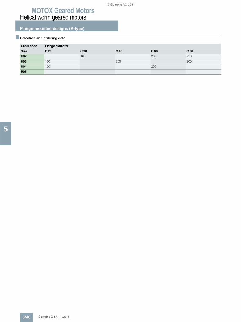
MOTOX Geared MotorsHelical worm geared motors
Flange-mounted designs (A-type)
5/46 Siemens D 87.1 · 2011
5
■ Selection and ordering data
Order code Flange diameter
Size C.28 C.38 C.48 C.68 C.88
H02 160 200 250
H03 120 200 300
H04 160 250
H05
© Siemens AG 2011
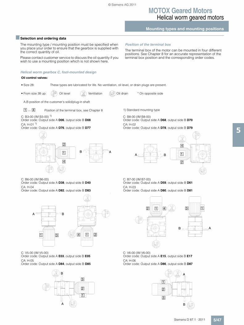
MOTOX Geared MotorsHelical worm geared motors
Mounting types and mounting positions
5/47Siemens D 87.1 · 2011
5
■ Selection and ordering data
The mounting type / mounting position must be specified when you place your order to ensure that the gearbox is supplied with the correct quantity of oil.
Please contact customer service to discuss the oil quantity if you wish to use a mounting position which is not shown here.
Position of the terminal box
The terminal box of the motor can be mounted in four different positions. See Chapter 8 for an accurate representation of the terminal box position and the corresponding order codes.
Helical worm gearbox C, foot-mounted design
Oil control valves:
• Size 28: These types are lubricated for life. No ventilation, oil level, or drain plugs are present.
• From size 38 up: Oil level Ventilation Oil drain * On opposite side
A,B position of the customer's solid/plug-in shaft
Position of the terminal box, see Chapter 8 1) Standard mounting type
C: B3-00 (IM B3-00) 1)
Order code: Output side A D06, output side B D08 CA: H-01 1)
Order code: Output side A D76, output side B D77
C: B8-00 (IM B8-00)Order code: Output side A D68, output side B D70 CA: H-02Order code: Output side A D78, output side B D79
C: B6-00 (IM B6-00)Order code: Output side A D38, output side B D40 CA: H-04Order code: Output side A D82, output side B D83
C: B7-00 (IM B7-00)Order code: Output side A D59, output side B D61CA: H-03Order code: Output side A D80, output side B D81
C: V5-00 (IM V5-00)Order code: Output side A E03, output side B E05 CA: H-05Order code: Output side A D84, output side B D85
C: V6-00 (IM V6-00)Order code: Output side A E15, output side B E17CA: H-06Order code: Output side A D86, output side B D87
1 ... 4
1
2
4
B A1
4
2
A B
1 3 1 24
BA
41 132
B A
3
2
1
B
A
1
2
3
A
B
© Siemens AG 2011
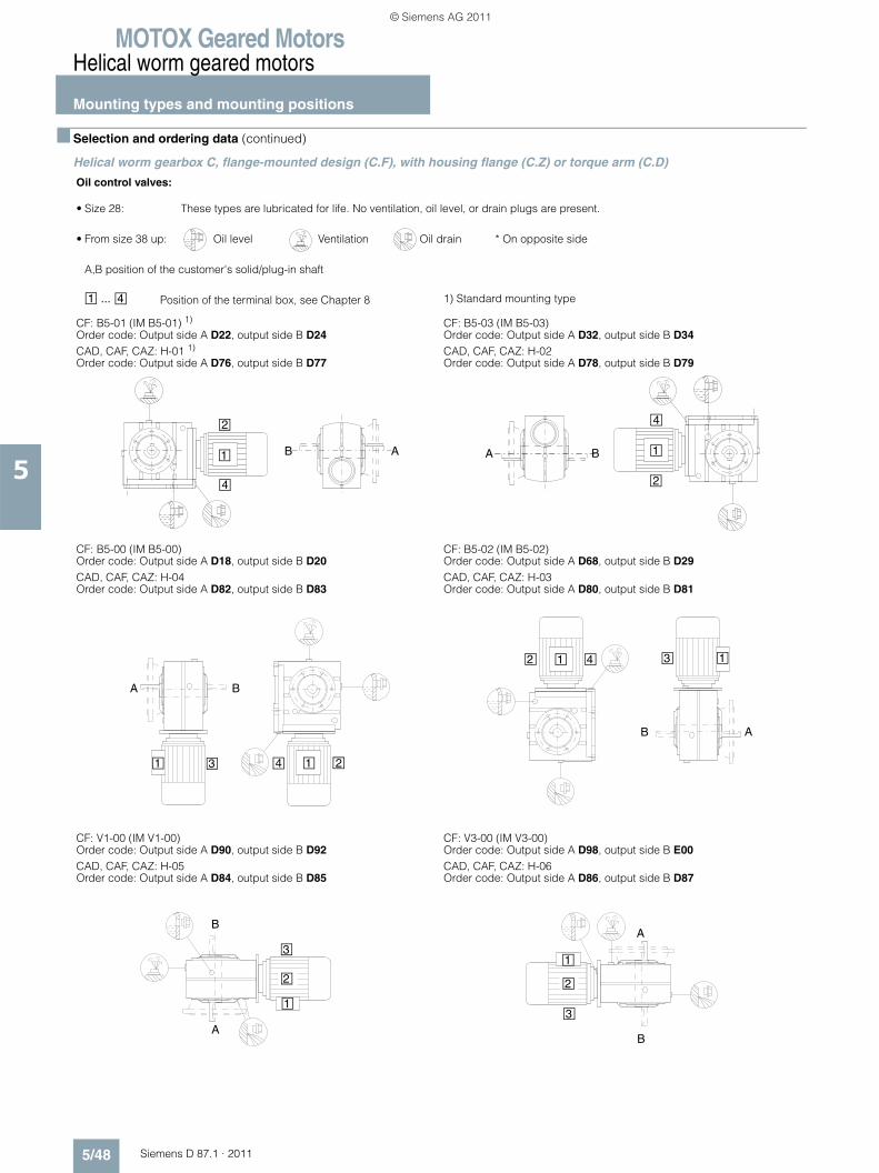
MOTOX Geared MotorsHelical worm geared motors
Mounting types and mounting positions
5/48 Siemens D 87.1 · 2011
5
■ Selection and ordering data (continued)
Helical worm gearbox C, flange-mounted design (C.F), with housing flange (C.Z) or torque arm (C.D)
Oil control valves:
• Size 28: These types are lubricated for life. No ventilation, oil level, or drain plugs are present.
• From size 38 up: Oil level Ventilation Oil drain * On opposite side
A,B position of the customer's solid/plug-in shaft
Position of the terminal box, see Chapter 8 1) Standard mounting type
CF: B5-01 (IM B5-01) 1)
Order code: Output side A D22, output side B D24 CAD, CAF, CAZ: H-01 1)
Order code: Output side A D76, output side B D77
CF: B5-03 (IM B5-03)Order code: Output side A D32, output side B D34 CAD, CAF, CAZ: H-02Order code: Output side A D78, output side B D79
CF: B5-00 (IM B5-00)Order code: Output side A D18, output side B D20 CAD, CAF, CAZ: H-04Order code: Output side A D82, output side B D83
CF: B5-02 (IM B5-02)Order code: Output side A D68, output side B D29 CAD, CAF, CAZ: H-03Order code: Output side A D80, output side B D81
CF: V1-00 (IM V1-00)Order code: Output side A D90, output side B D92 CAD, CAF, CAZ: H-05Order code: Output side A D84, output side B D85
CF: V3-00 (IM V3-00)Order code: Output side A D98, output side B E00 CAD, CAF, CAZ: H-06Order code: Output side A D86, output side B D87
1 ... 4
1
2
4
B A 1
4
2
A B
1 3 1 24
BA
2 41 1
B A
3
3
2
1
B
A
1
2
3
A
B
© Siemens AG 2011
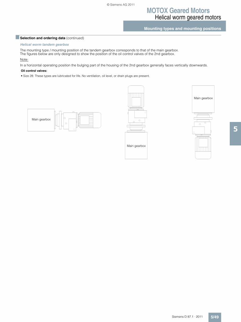
MOTOX Geared MotorsHelical worm geared motors
Mounting types and mounting positions
5/49Siemens D 87.1 · 2011
5
■ Selection and ordering data (continued)
Helical worm tandem gearbox
The mounting type / mounting position of the tandem gearbox corresponds to that of the main gearbox. The figures below are only designed to show the position of the oil control valves of the 2nd gearbox.
Note:
In a horizontal operating position the bulging part of the housing of the 2nd gearbox generally faces vertically downwards.
Oil control valves:
• Size 28: These types are lubricated for life. No ventilation, oil level, or drain plugs are present.
Main gearbox
Main gearbox
Main gearbox
© Siemens AG 2011
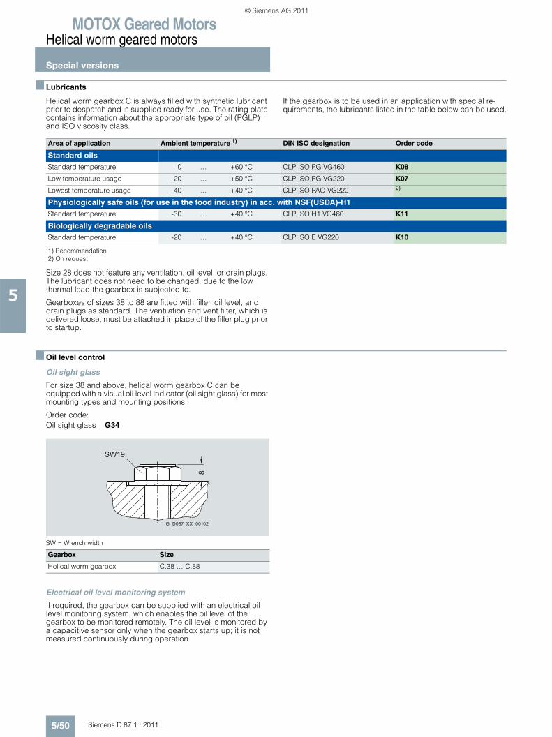
MOTOX Geared MotorsHelical worm geared motors
Special versions
5/50 Siemens D 87.1 · 2011
5
■ Lubricants
Helical worm gearbox C is always filled with synthetic lubricant prior to despatch and is supplied ready for use. The rating plate contains information about the appropriate type of oil (PGLP) and ISO viscosity class.
If the gearbox is to be used in an application with special re-quirements, the lubricants listed in the table below can be used.
Size 28 does not feature any ventilation, oil level, or drain plugs. The lubricant does not need to be changed, due to the low thermal load the gearbox is subjected to.
Gearboxes of sizes 38 to 88 are fitted with filler, oil level, and drain plugs as standard. The ventilation and vent filter, which is delivered loose, must be attached in place of the filler plug prior to startup.
■ Oil level control
Oil sight glass
For size 38 and above, helical worm gearbox C can be equipped with a visual oil level indicator (oil sight glass) for most mounting types and mounting positions.
Order code:Oil sight glass G34
SW = Wrench width
Electrical oil level monitoring system
If required, the gearbox can be supplied with an electrical oil level monitoring system, which enables the oil level of the gearbox to be monitored remotely. The oil level is monitored by a capacitive sensor only when the gearbox starts up; it is not measured continuously during operation.
Area of application Ambient temperature 1) DIN ISO designation Order code
Standard oilsStandard temperature 0 … +60 °C CLP ISO PG VG460 K08
Low temperature usage -20 … +50 °C CLP ISO PG VG220 K07
Lowest temperature usage -40 … +40 °C CLP ISO PAO VG220 2)
Physiologically safe oils (for use in the food industry) in acc. with NSF(USDA)-H1Standard temperature -30 … +40 °C CLP ISO H1 VG460 K11
Biologically degradable oilsStandard temperature -20 … +40 °C CLP ISO E VG220 K10
1) Recommendation2) On request
Gearbox Size
Helical worm gearbox C.38 … C.88
8
G_D087_XX_00102
SW19
© Siemens AG 2011
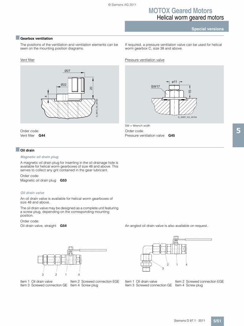
MOTOX Geared MotorsHelical worm geared motors
Special versions
5/51Siemens D 87.1 · 2011
5
■ Gearbox ventilation
The positions of the ventilation and ventilation elements can be seen on the mounting position diagrams.
If required, a pressure ventilation valve can be used for helical worm gearbox C, size 38 and above.
Vent filter
Order code:Vent filter G44
Pressure ventilation valve
SW = Wrench width
Order code:Pressure ventilation valve G45
■ Oil drain
Magnetic oil drain plug
A magnetic oil drain plug for inserting in the oil drainage hole is available for helical worm gearboxes of size 48 and above. This serves to collect any grit contained in the gear lubricant.
Order code:Magnetic oil drain plug G53
Oil drain valve
An oil drain valve is available for helical worm gearboxes of size 48 and above.
The oil drain valve may be designed as a complete unit featuring a screw plug, depending on the corresponding mounting position.
Order code: Oil drain valve, straight G54
Item 1 Oil drain valve Item 2 Screwed connection EGEItem 3 Screwed connection GE Item 4 Screw plug
An angled oil drain valve is also available on request..
Item 1 Oil drain valve Item 2 Screwed connection EGEItem 3 Screwed connection GE Item 4 Screw plug
� � �
� � �
��
�
���������� �
15
ø11
G_D087_XX_00104
SW17
3 2 1 4
32 1 4
© Siemens AG 2011
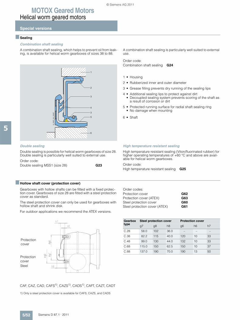
MOTOX Geared MotorsHelical worm geared motors
Special versions
5/52 Siemens D 87.1 · 2011
5
■ Sealing
Combination shaft sealing
A combination shaft sealing, which helps to prevent oil from leak-ing, is available for helical worm gearboxes of sizes 38 to 88.
A combination shaft sealing is particularly well suited to external use.
Order code:Combination shaft sealing G24
1 • Housing
2 • Rubberized inner and outer diameter
3 • Grease filling prevents dry running of the sealing lips
4 • Additional sealing lips to protect against dirt• Decoupled sealing system prevents scoring of the shaft as
a result of corrosion or dirt
5 • Protected running surface for radial shaft sealing ring• No damage when mounting
6 • Shaft
Double sealing
Double sealing is possible for helical worm gearboxes of size 28. Double sealing is particularly well suited to external use.
Order code:Double sealing MSS1 (size 28) G23
High temperature resistant sealing
High temperature resistant sealing (Viton/fluorinated rubber) for higher operating temperatures of +60 °C and above are avail-able for helical worm gearboxes.
Order code:High temperature resistant sealing G25
■ Hollow shaft cover (protection cover)
Gearboxes with hollow shafts can be fitted with a fixed protec-tion cover. Gearboxes of size 28 are fitted with a steel protection cover as standard.
The steel protection cover can only be used for gearboxes with hollow shaft and shrink disk.
For outdoor applications we recommend the ATEX versions.
Order codes:Protection cover G62Protection cover (ATEX) G63Steel protection cover G60Steel protection cover (ATEX) G61
CAF, CAZ, CAD, CAFS1), CAZS1), CADS1), CAFT, CAZT, CADT
1) Only a steel protection cover is available for CAFS, CAZS, and CADS
G_D
087_
XX
_000
87
1
2
3
3
5
4
6
Protection
Steel
Protectioncover
cover
Gearbox type
Steel protection cover Protection cover
g7 g8 h8 g6 h6 h7
C.28 58.0 102 36.0 – – –
C.38 82.2 115 40.0 120 10 33
C.48 99.0 130 44.0 132 10 33
C.68 115.0 150 62.5 150 10 37
C.88 137.0 190 70.0 190 13 50
© Siemens AG 2011
MOTOX Geared MotorsHelical worm geared motors
Special versions
5/53Siemens D 87.1 · 2011
5
■ Radially reinforced output shaft bearings
The bearings of the MOTOX gearboxes are dimensioned such that they are strong enough to withstand most application cases.
However, the gearboxes can be fitted with a radially reinforced output shaft bearing arrangement for applications with particu-larly high radial forces.
Order code:Radially reinforced output shaft bearings G20
■ 2nd output shaft extension
If required, helical worms in a foot-mounted design with solid shaft are available with a 2nd shaft extension.
See the dimension drawings for the corresponding design for the relevant dimensions.
Order code:2nd output shaft extension G73
© Siemens AG 2011
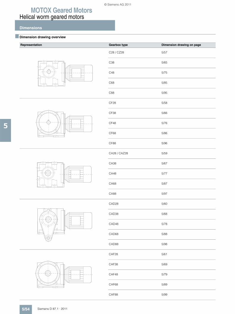
MOTOX Geared MotorsHelical worm geared motors
Dimensions
5/54 Siemens D 87.1 · 2011
5
■ Dimension drawing overview
Representation Gearbox type Dimension drawing on page
C28 / CZ28 5/57
C38 5/65
C48 5/75
C68 5/85
C88 5/95
CF28 5/58
CF38 5/66
CF48 5/76
CF68 5/86
CF88 5/96
CA28 / CAZ28 5/59
CA38 5/67
CA48 5/77
CA68 5/87
CA88 5/97
CAD28 5/60
CAD38 5/68
CAD48 5/78
CAD68 5/88
CAD88 5/98
CAF28 5/61
CAF38 5/69
CAF48 5/79
CAF68 5/89
CAF88 5/99
© Siemens AG 2011
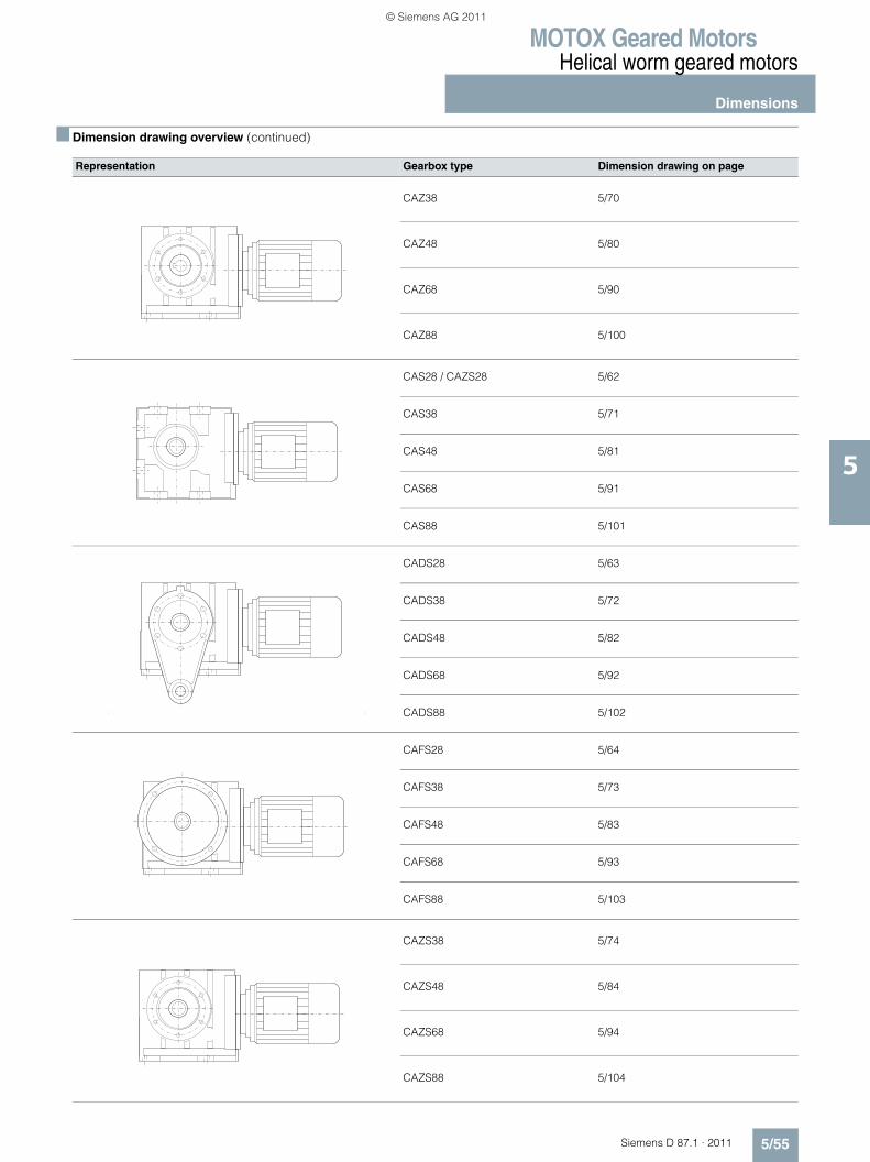
MOTOX Geared MotorsHelical worm geared motors
Dimensions
5/55Siemens D 87.1 · 2011
5
■ Dimension drawing overview (continued)
Representation Gearbox type Dimension drawing on page
CAZ38 5/70
CAZ48 5/80
CAZ68 5/90
CAZ88 5/100
CAS28 / CAZS28 5/62
CAS38 5/71
CAS48 5/81
CAS68 5/91
CAS88 5/101
CADS28 5/63
CADS38 5/72
CADS48 5/82
CADS68 5/92
CADS88 5/102
CAFS28 5/64
CAFS38 5/73
CAFS48 5/83
CAFS68 5/93
CAFS88 5/103
CAZS38 5/74
CAZS48 5/84
CAZS68 5/94
CAZS88 5/104
© Siemens AG 2011
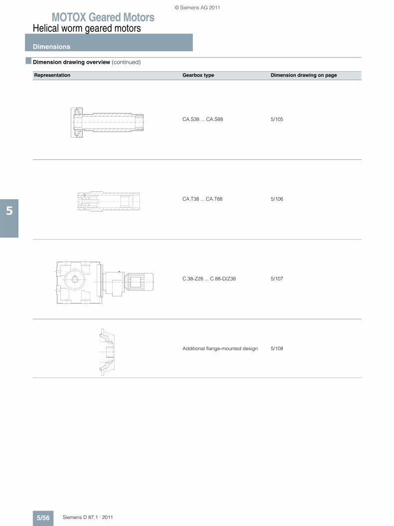
MOTOX Geared MotorsHelical worm geared motors
Dimensions
5/56 Siemens D 87.1 · 2011
5
■ Dimension drawing overview (continued)
Representation Gearbox type Dimension drawing on page
CA.S38 ... CA.S88 5/105
CA.T38 ... CA.T88 5/106
C.38-Z28 ... C.88-D/Z38 5/107
Additional flange-mounted design 5/108
© Siemens AG 2011
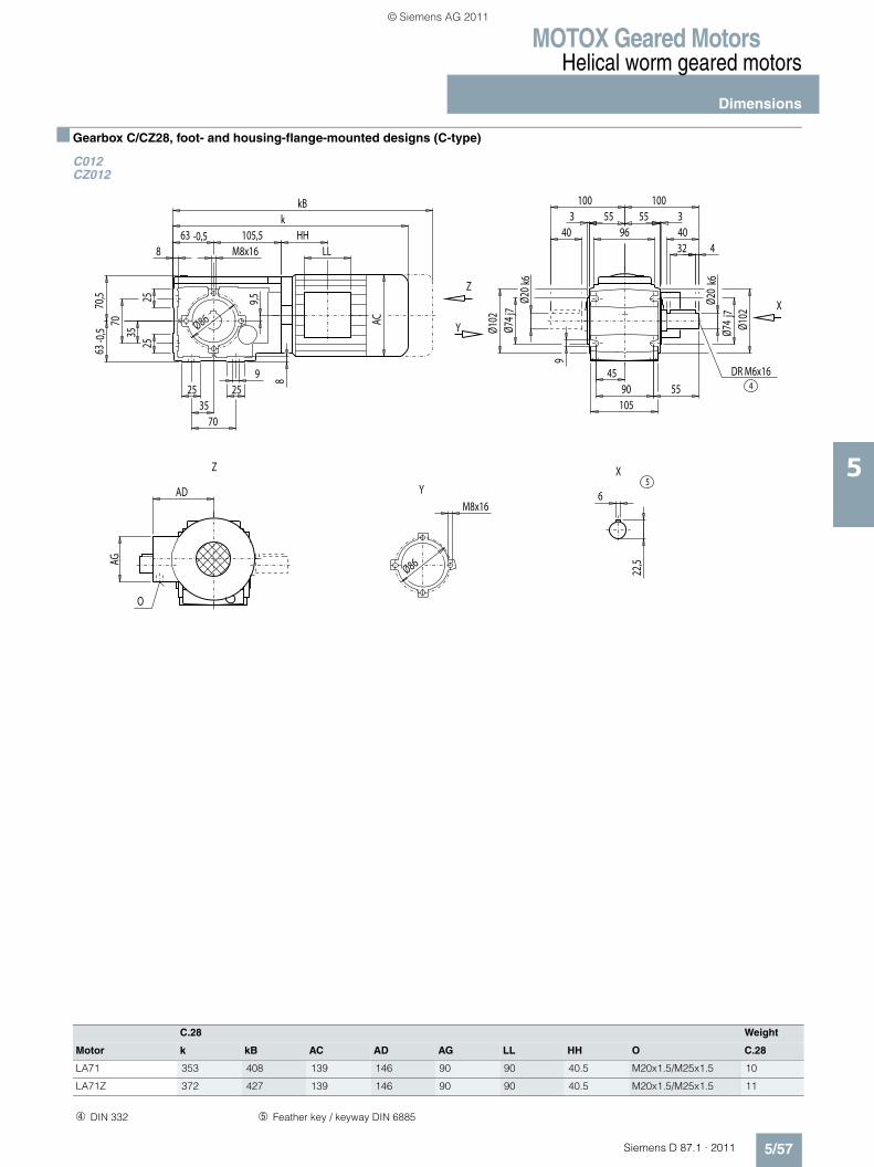
MOTOX Geared MotorsHelical worm geared motors
Dimensions
5/57Siemens D 87.1 · 2011
5
■ Gearbox C/CZ28, foot- and housing-flange-mounted designs (C-type)
C012CZ012
C.28 Weight
Motor k kB AC AD AG LL HH O C.28
LA71 353 408 139 146 90 90 40.5 M20x1.5/M25x1.5 10
LA71Z 372 427 139 146 90 90 40.5 M20x1.5/M25x1.5 11
Z
Z
X
X
Y
Y5
O
4DR M6x16
AG
LLHH
8
55
55 55
Ø86
Ø86
100100
404032 4
Ø20
k6
Ø20
k6
22,5
6AD
963 3
Ø74
j7Ø1
02
Ø74 j
7
9
Ø102
4590
105
AC
8
7035
925 25
2525
9,5
105,5k
kB
63 -0,5M8x16
M8x16
3570
63-0
,570
,5
➃ DIN 332 ➄ Feather key / keyway DIN 6885
© Siemens AG 2011
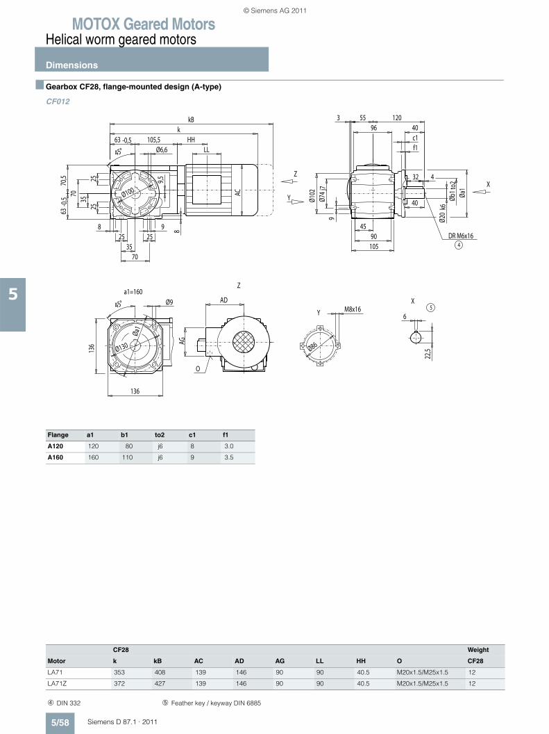
MOTOX Geared MotorsHelical worm geared motors
Dimensions
5/58 Siemens D 87.1 · 2011
5
■ Gearbox CF28, flange-mounted design (A-type)
CF012
Flange a1 b1 to2 c1 f1
A120 120 80 j6 8 3.0
A160 160 110 j6 9 3.5
Y
Y
Z
Z
X
Xa1=160
5
O
4DR M6x16
AG
LLHH
8
Øa1
136
Ø86
Øa1
Ø100
Øb1 t
o2
40120
c1
136
Ø130
Ø6,6
Ø9
40
32 4
Ø20
k6
f1
22,5
6
AD
963 55
Ø74
j79
Ø102
4590
105AC
8
7035
925 25
2525
9,5
105,5k
kB
63 -0,5
3570
63-0
,570
,5
45°
45°M8x16
CF28 Weight
Motor k kB AC AD AG LL HH O CF28
LA71 353 408 139 146 90 90 40.5 M20x1.5/M25x1.5 12
LA71Z 372 427 139 146 90 90 40.5 M20x1.5/M25x1.5 12
➃ DIN 332 ➄ Feather key / keyway DIN 6885
© Siemens AG 2011
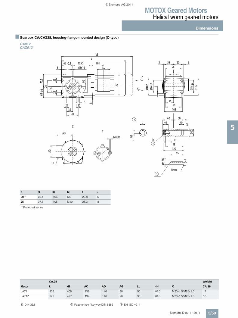
MOTOX Geared MotorsHelical worm geared motors
Dimensions
5/59Siemens D 87.1 · 2011
5
■ Gearbox CA/CAZ28, housing-flange-mounted design (C-type)
CA012CAZ012
d l9 l8 M t u
20 *) 23.4 106 M6 22.8 6
25 27.6 105 M10 28.3 8
*) Preferred series
5
4
O
1M
Rmax1
Y
Y
Z
Z
AG
LLHH
8
5555
Ø86
M8x16
Ø86
Ødh6
ØdH7
Ø40
uJS
9AD
963 3
Ø74
j7Ø1
02
Ø74 j
79
Ø102
95
l9
120l8
604040
62
4590
105
AC
8
7035
925 25
2525
9,5
105,5k
kB
63 -0,5M8x16
3570
63-0
,570
,5
t
CA.28 Weight
Motor k kB AC AD AG LL HH O CA.28
LA71 353 408 139 146 90 90 40.5 M20x1.5/M25x1.5 9
LA71Z 372 427 139 146 90 90 40.5 M20x1.5/M25x1.5 10
➃ DIN 332 ➄ Feather key / keyway DIN 6885 ➀ EN ISO 4014
© Siemens AG 2011
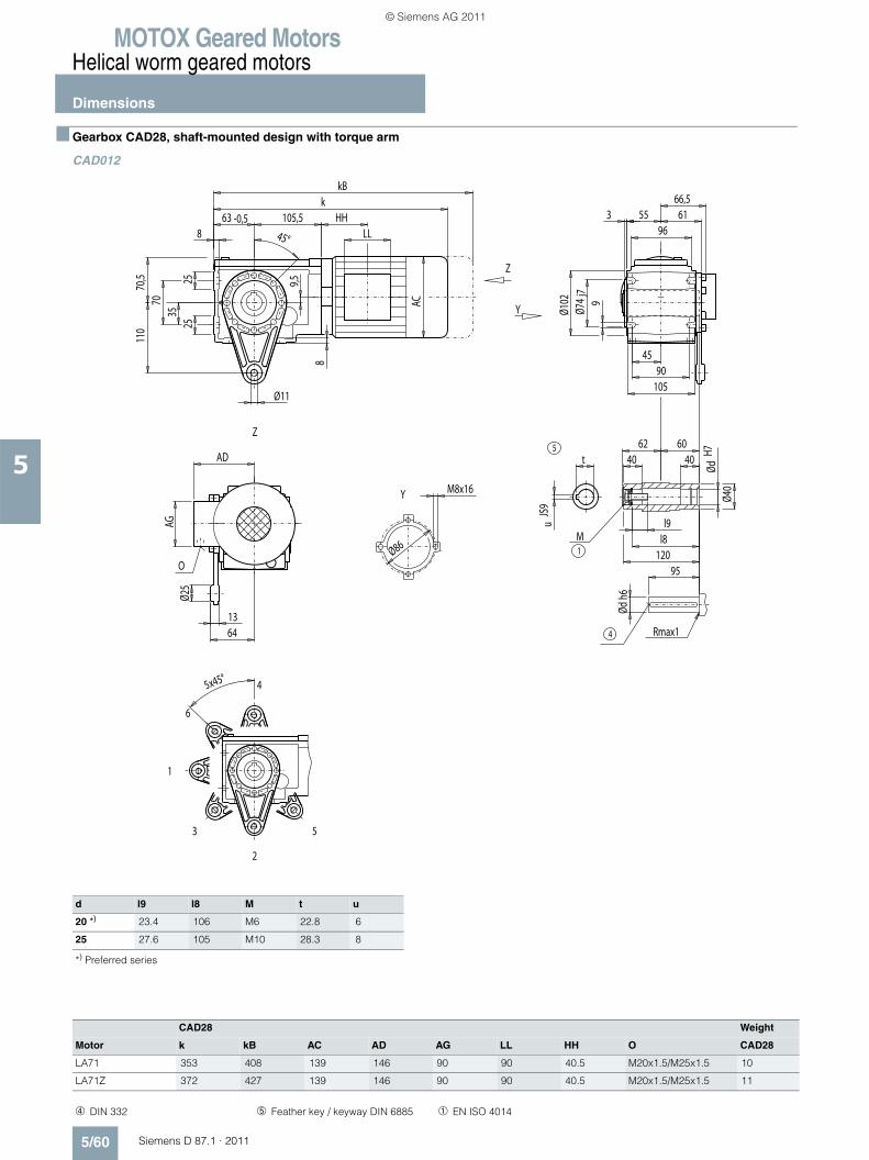
MOTOX Geared MotorsHelical worm geared motors
Dimensions
5/60 Siemens D 87.1 · 2011
5
■ Gearbox CAD28, shaft-mounted design with torque arm
CAD012
d l9 l8 M t u
20 *) 23.4 106 M6 22.8 6
25 27.6 105 M10 28.3 8
*) Preferred series
Y
Y
Z
Z
2
3
1
6
4
5
Rmax1
5
4
O1M
AG
LLHH
5x45°
55 6166,5
Ø86
9045
105
1364
Ø25
110
45°8
Ødh6
ØdH7
Ø40
uJS
9
AD
963
Ø11
Ø74
j79
Ø102
95
l9
120l8
604040
62
AC
8
2525
9,5
105,5k
kB
63 -0,5
3570
70,5
t
M8x16
CAD28 Weight
Motor k kB AC AD AG LL HH O CAD28
LA71 353 408 139 146 90 90 40.5 M20x1.5/M25x1.5 10
LA71Z 372 427 139 146 90 90 40.5 M20x1.5/M25x1.5 11
➃ DIN 332 ➄ Feather key / keyway DIN 6885 ➀ EN ISO 4014
© Siemens AG 2011
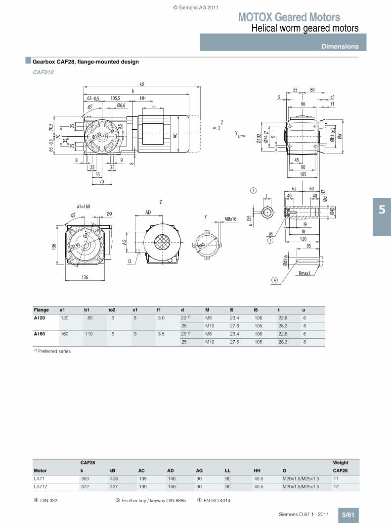
MOTOX Geared MotorsHelical worm geared motors
Dimensions
5/61Siemens D 87.1 · 2011
5
■ Gearbox CAF28, flange-mounted design
CAF012
Y
Y
Z
Za1=160
Rmax1
5
4
O
1M
AG
LLHH
Øa1
136
136
Ø130
Ø945°
8
Ø86
Øb1
to2
Øa1
Ødh6
ØdH7
Ø40
uJS
9
AD
96
55 803
Ø74
j79
Ø102
95
l9
120l8
604040
62
4590
105AC
8
7035
925 25
2525
9,5
105,5k
kB
63 -0,5
3570
63-0
,570
,5
t
Ø100
c1
Ø6,6 f145°
M8x16
Flange a1 b1 to2 c1 f1 d M l9 l8 t u
A120 120 80 j6 8 3.0 20 *) M6 23.4 106 22.8 6
25 M10 27.6 105 28.3 8
A160 160 110 j6 9 3.5 20 *) M6 23.4 106 22.8 6
25 M10 27.6 105 28.3 8
*) Preferred series
CAF28 Weight
Motor k kB AC AD AG LL HH O CAF28
LA71 353 408 139 146 90 90 40.5 M20x1.5/M25x1.5 11
LA71Z 372 427 139 146 90 90 40.5 M20x1.5/M25x1.5 12
➃ DIN 332 ➄ Feather key / keyway DIN 6885 ➀ EN ISO 4014
© Siemens AG 2011
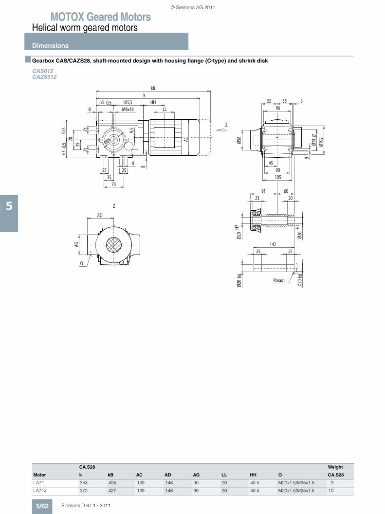
MOTOX Geared MotorsHelical worm geared motors
Dimensions
5/62 Siemens D 87.1 · 2011
5
■ Gearbox CAS/CAZS28, shaft-mounted design with housing flange (C-type) and shrink disk
CAS012CAZS012
CA.S28 Weight
Motor k kB AC AD AG LL HH O CA.S28
LA71 353 408 139 146 90 90 40.5 M20x1.5/M25x1.5 9
LA71Z 372 427 139 146 90 90 40.5 M20x1.5/M25x1.5 10
Z
Z
Rmax1
O
AG
LLHH
8
5555
Ø86 Ø58
Ø20
h6
25 25142
9
609120
Ø20
H7
Ø20
H7Ø2
0h6
23
AD
963
Ø102
4590
105
AC
8
7035
925 25
2525
9,5
105,5k
kB
63 -0,5M8x16
3570
63-0
,570
,5
Ø74
j7
© Siemens AG 2011
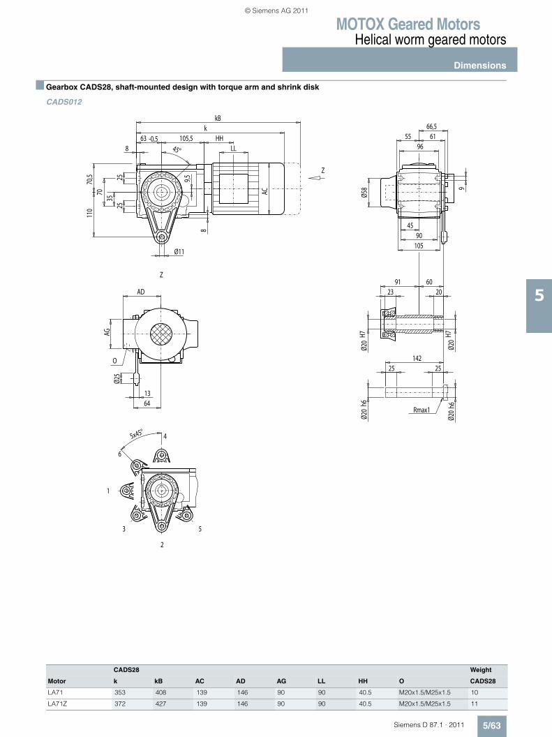
MOTOX Geared MotorsHelical worm geared motors
Dimensions
5/63Siemens D 87.1 · 2011
5
■ Gearbox CADS28, shaft-mounted design with torque arm and shrink disk
CADS012
CADS28 Weight
Motor k kB AC AD AG LL HH O CADS28
LA71 353 408 139 146 90 90 40.5 M20x1.5/M25x1.5 10
LA71Z 372 427 139 146 90 90 40.5 M20x1.5/M25x1.5 11
Z
Z
2
3
1
6
4
5
Rmax1
O
AG
LLHH
5x45°
61
9
Ø58
Ø20
h625 25
142
609120
Ø20
H7
Ø20
H7Ø2
0h6
110
9045
105
13
45°
AD
96
Ø11
AC
8
2525
9,5
105,5k
kB
63 -0,58
3570
70,5
64
Ø25
5566,5
23
© Siemens AG 2011
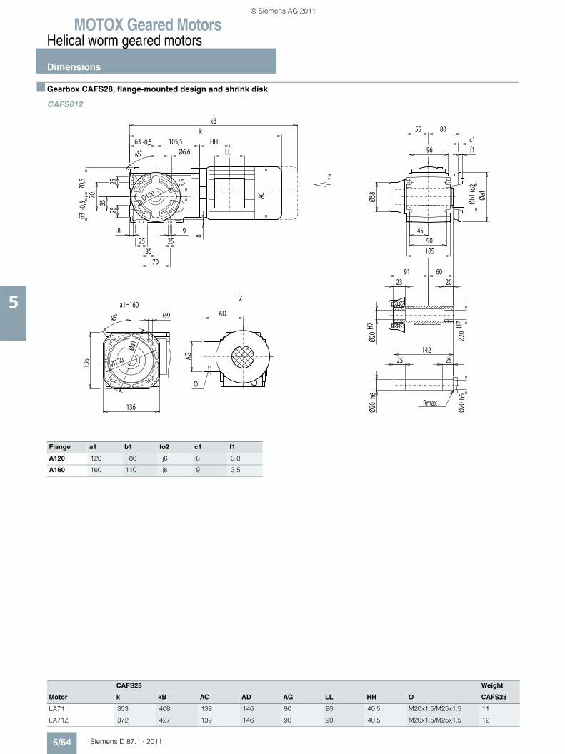
MOTOX Geared MotorsHelical worm geared motors
Dimensions
5/64 Siemens D 87.1 · 2011
5
■ Gearbox CAFS28, flange-mounted design and shrink disk
CAFS012
Flange a1 b1 to2 c1 f1
A120 120 80 j6 8 3.0
A160 160 110 j6 9 3.5
CAFS28 Weight
Motor k kB AC AD AG LL HH O CAFS28
LA71 353 408 139 146 90 90 40.5 M20x1.5/M25x1.5 11
LA71Z 372 427 139 146 90 90 40.5 M20x1.5/M25x1.5 12
Z
Za1=160
Rmax1
O
AG
LLHH
Øa1
136
136
Ø130
Ø945°
8
Ø58
6091
96
55
4590
105
Ø20
h6
25 25142
20
Ø20
H7
Ø20
H7Ø2
0h6
Øb1
to2
Øa1
AD
80
AC
8
7035
925 25
2525
9,5
105,5k
kB
63 -0,5
3570
63-0
,570
,5
Ø100
c1
Ø6,6 f145°
23
© Siemens AG 2011
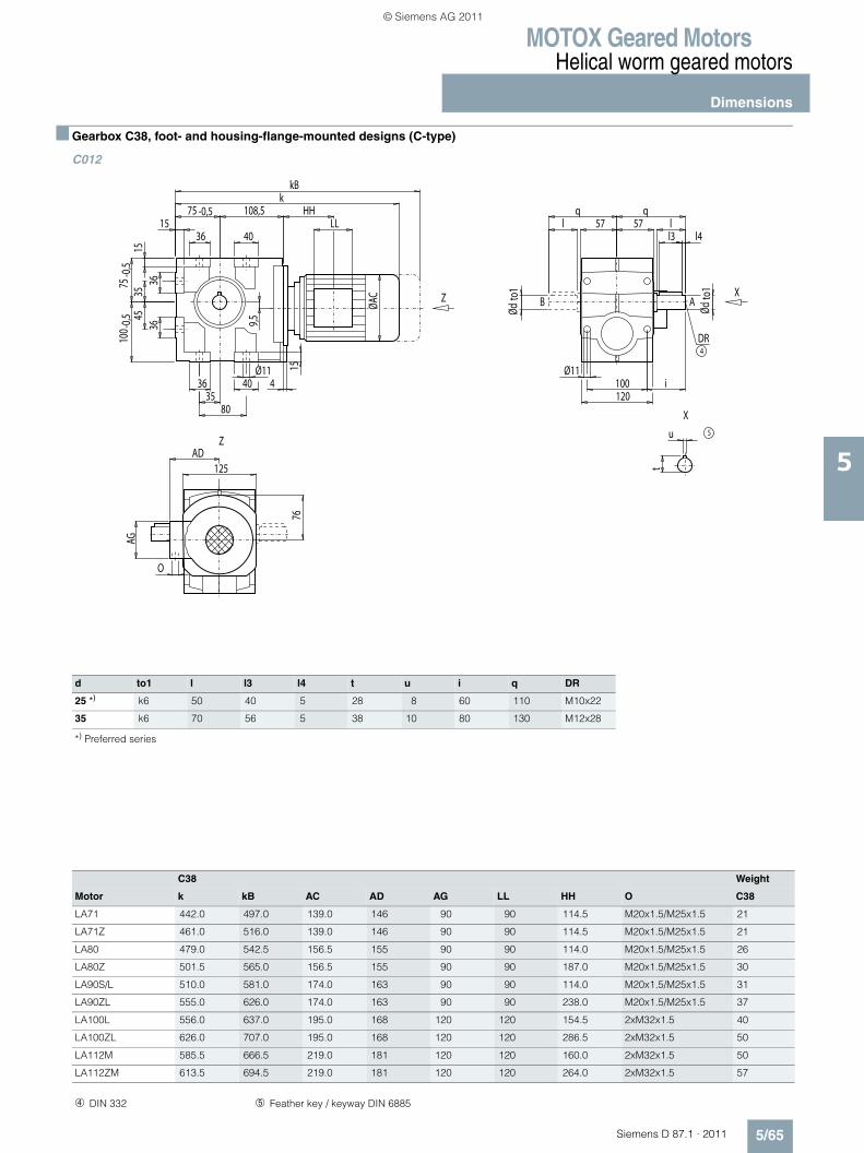
MOTOX Geared MotorsHelical worm geared motors
Dimensions
5/65Siemens D 87.1 · 2011
5
■ Gearbox C38, foot- and housing-flange-mounted designs (C-type)
C012
d to1 l l3 l4 t u i q DR
25 *) k6 50 40 5 28 8 60 110 M10x22
35 k6 70 56 5 38 10 80 130 M12x28
*) Preferred series
C38 Weight
Motor k kB AC AD AG LL HH O C38
LA71 442.0 497.0 139.0 146 90 90 114.5 M20x1.5/M25x1.5 21
LA71Z 461.0 516.0 139.0 146 90 90 114.5 M20x1.5/M25x1.5 21
LA80 479.0 542.5 156.5 155 90 90 114.0 M20x1.5/M25x1.5 26
LA80Z 501.5 565.0 156.5 155 90 90 187.0 M20x1.5/M25x1.5 30
LA90S/L 510.0 581.0 174.0 163 90 90 114.0 M20x1.5/M25x1.5 31
LA90ZL 555.0 626.0 174.0 163 90 90 238.0 M20x1.5/M25x1.5 37
LA100L 556.0 637.0 195.0 168 120 120 154.5 2xM32x1.5 40
LA100ZL 626.0 707.0 195.0 168 120 120 286.5 2xM32x1.5 50
LA112M 585.5 666.5 219.0 181 120 120 160.0 2xM32x1.5 50
LA112ZM 613.5 694.5 219.0 181 120 120 264.0 2xM32x1.5 57
X
X
Z
Z
4DR
AB
5
HH
AG
LL
Ødto
1
Ødto
1
35
15
9,5
l3 l4
7615
4
80
O
125AD
Ø11
l 57 57 lq q
Ø11100 i120
3545
100 -
0,575
-0,5
36 40
1575 -0,5 108,5
kkB
ØAC
4036
3636
u
t
➃ DIN 332 ➄ Feather key / keyway DIN 6885
© Siemens AG 2011

MOTOX Geared MotorsHelical worm geared motors
Dimensions
5/66 Siemens D 87.1 · 2011
5
■ Gearbox CF38, flange-mounted design (A-type)
CF012
A
4DR M10x22
5
X
X
Z
Z
HH
AG
LL
35 38,5M10x17
50
60100
10
O
76
AD125
40 5
Ø25 k
6Ø1
10j6
Ø160
57
10 3,550
134
4
11737
63,5
30
7410
0-0
,5 ØAC
45°75 108,5
Ø9
kkB
9,5
8
28
Ø130
CF38 Weight
Motor k kB AC AD AG LL HH O CF38
LA71 442.0 497.0 139.0 146 90 90 114.5 M20x1.5/M25x1.5 25
LA71Z 461.0 516.0 139.0 146 90 90 114.5 M20x1.5/M25x1.5 25
LA80 479.0 542.5 156.5 155 90 90 114.0 M20x1.5/M25x1.5 30
LA80Z 501.5 565.0 156.5 155 90 90 187.0 M20x1.5/M25x1.5 34
LA90S/L 510.0 581.0 174.0 163 90 90 114.0 M20x1.5/M25x1.5 34
LA90ZL 555.0 626.0 174.0 163 90 90 238.0 M20x1.5/M25x1.5 40
LA100L 556.0 637.0 195.0 168 120 120 154.5 2xM32x1.5 44
LA100ZL 626.0 707.0 195.0 168 120 120 286.5 2xM32x1.5 54
LA112M 585.5 666.5 219.0 181 120 120 160.0 2xM32x1.5 54
LA112ZM 613.5 694.5 219.0 181 120 120 264.0 2xM32x1.5 61
➃ DIN 332 ➄ Feather key / keyway DIN 6885
© Siemens AG 2011
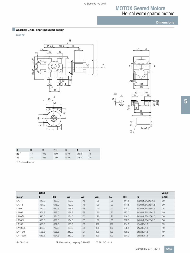
MOTOX Geared MotorsHelical worm geared motors
Dimensions
5/67Siemens D 87.1 · 2011
5
■ Gearbox CA38, shaft-mounted design
CA012
d l9 l8 l11 M t u
25 *) 17 105 100 M10 28.3 8
30 31 102 90 M10 33.3 8
*) Preferred series
Z
Z
4
max2.5R
5
1
M
AB
AG
LL
Ødh6
t
ØdH7u
JS9
Ø45
l9
44 44
l8120
l11
63 60
35
15
9,576
15
4
80
O
125AD
Ø11
57 57
Ø11100120
3545
100 -
0,575
-0,5
36 40
1575 -0,5 108,5
kkB
ØAC
4036
3636
HH
CA38 Weight
Motor k kB AC AD AG LL HH O CA38
LA71 442.0 497.0 139.0 146 90 90 114.5 M20x1.5/M25x1.5 20
LA71Z 461.0 516.0 139.0 146 90 90 114.5 M20x1.5/M25x1.5 20
LA80 479.0 542.5 156.5 155 90 90 114.0 M20x1.5/M25x1.5 25
LA80Z 501.5 565.0 156.5 155 90 90 187.0 M20x1.5/M25x1.5 29
LA90S/L 510.0 581.0 174.0 163 90 90 114.0 M20x1.5/M25x1.5 30
LA90ZL 555.0 626.0 174.0 163 90 90 238.0 M20x1.5/M25x1.5 36
LA100L 556.0 637.0 195.0 168 120 120 154.5 2xM32x1.5 39
LA100ZL 626.0 707.0 195.0 168 120 120 286.5 2xM32x1.5 49
LA112M 585.5 666.5 219.0 181 120 120 160.0 2xM32x1.5 49
LA112ZM 613.5 694.5 219.0 181 120 120 264.0 2xM32x1.5 56
➃ DIN 332 ➄ Feather key / keyway DIN 6885 ➀ EN ISO 4014
© Siemens AG 2011
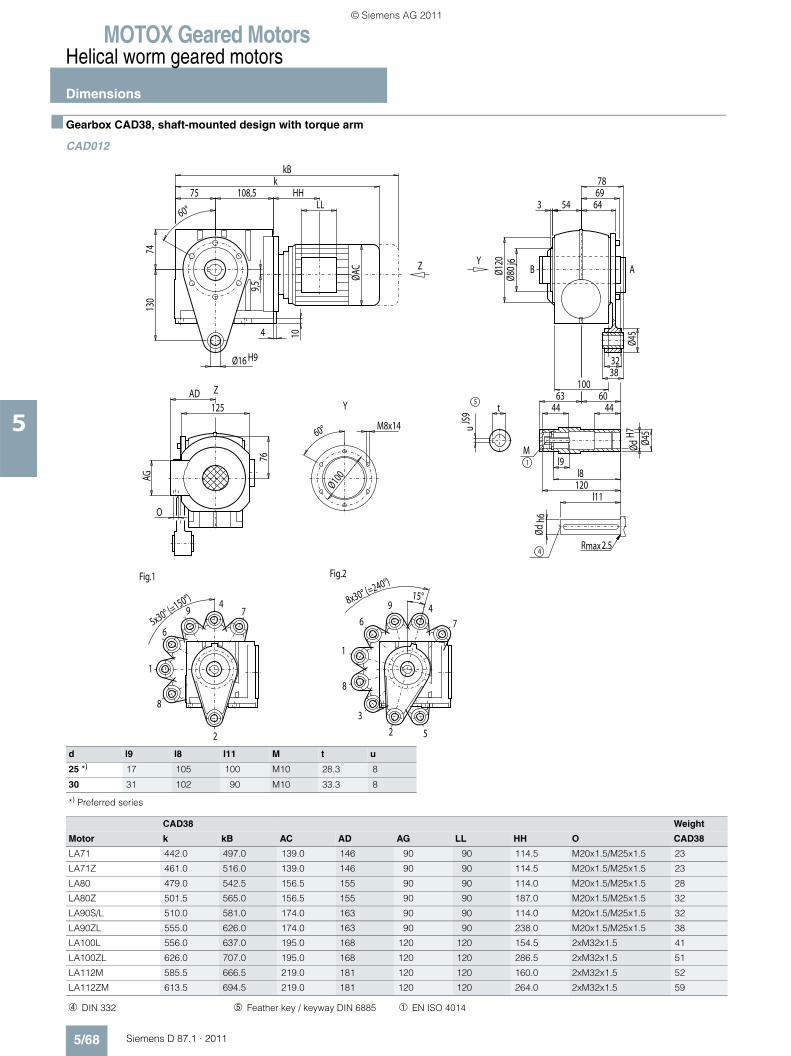
MOTOX Geared MotorsHelical worm geared motors
Dimensions
5/68 Siemens D 87.1 · 2011
5
■ Gearbox CAD38, shaft-mounted design with torque arm
CAD012
d l9 l8 l11 M t u
25 *) 17 105 100 M10 28.3 8
30 31 102 90 M10 33.3 8
*) Preferred series
2
4
6
8
1
79
Fig.1
2
46
8
Fig.2
1
3
5
7
9
max2.5R
5
1
M
4
ABY
Y
Z
Z
HH
M8x1460°
Ø100AG
LL
5x30° (=150°) 8x30° (=240°)
15°
78
54
Ødh6
ØdH7
Ø45
6469
130
32Ø16 H938
360°
Ø80 j
6
100
t
uJS
9
Ø45
l9
44 44
l8120
l11
63 60
10
O
76
AD125
Ø120
4
74
ØAC
75 108,5k
9,5
kB
CAD38 Weight
Motor k kB AC AD AG LL HH O CAD38
LA71 442.0 497.0 139.0 146 90 90 114.5 M20x1.5/M25x1.5 23
LA71Z 461.0 516.0 139.0 146 90 90 114.5 M20x1.5/M25x1.5 23
LA80 479.0 542.5 156.5 155 90 90 114.0 M20x1.5/M25x1.5 28
LA80Z 501.5 565.0 156.5 155 90 90 187.0 M20x1.5/M25x1.5 32
LA90S/L 510.0 581.0 174.0 163 90 90 114.0 M20x1.5/M25x1.5 32
LA90ZL 555.0 626.0 174.0 163 90 90 238.0 M20x1.5/M25x1.5 38
LA100L 556.0 637.0 195.0 168 120 120 154.5 2xM32x1.5 41
LA100ZL 626.0 707.0 195.0 168 120 120 286.5 2xM32x1.5 51
LA112M 585.5 666.5 219.0 181 120 120 160.0 2xM32x1.5 52
LA112ZM 613.5 694.5 219.0 181 120 120 264.0 2xM32x1.5 59
➃ DIN 332 ➄ Feather key / keyway DIN 6885 ➀ EN ISO 4014
© Siemens AG 2011
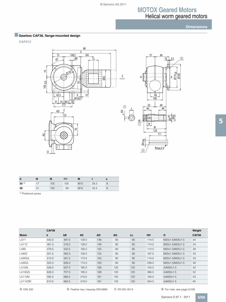
MOTOX Geared MotorsHelical worm geared motors
Dimensions
5/69Siemens D 87.1 · 2011
5
■ Gearbox CAF38, flange-mounted design
CAF012
Z
Z
max2.5R
5
1
M
4
AB
6HH
AG
LL
Ødh6
60
57 84
t
ØdH7
uJS
9
Ø45
l9
44 44
l8120
l11
63 60
100
10
O
76
AD125
Ø110
j6Ø1
60
10 3,5
M10x174
11737
63,5
3035 38,5
7410
0 -0,5
ØAC
45°75 108,5
Ø9
kkB
9,5
Ø130
d l9 l8 l11 M t u
25 *) 17 105 100 M10 28.3 8
30 31 102 90 M10 33.3 8
*) Preferred series
CAF38 Weight
Motor k kB AC AD AG LL HH O CAF38
LA71 442.0 497.0 139.0 146 90 90 114.5 M20x1.5/M25x1.5 24
LA71Z 461.0 516.0 139.0 146 90 90 114.5 M20x1.5/M25x1.5 24
LA80 479.0 542.5 156.5 155 90 90 114.0 M20x1.5/M25x1.5 29
LA80Z 501.5 565.0 156.5 155 90 90 187.0 M20x1.5/M25x1.5 33
LA90S/L 510.0 581.0 174.0 163 90 90 114.0 M20x1.5/M25x1.5 33
LA90ZL 555.0 626.0 174.0 163 90 90 238.0 M20x1.5/M25x1.5 39
LA100L 556.0 637.0 195.0 168 120 120 154.5 2xM32x1.5 42
LA100ZL 626.0 707.0 195.0 168 120 120 286.5 2xM32x1.5 52
LA112M 585.5 666.5 219.0 181 120 120 160.0 2xM32x1.5 53
LA112ZM 613.5 694.5 219.0 181 120 120 264.0 2xM32x1.5 60
➃ DIN 332 ➄ Feather key / keyway DIN 6885 ➀ EN ISO 4014 ➅ For note, see page 5/108
© Siemens AG 2011
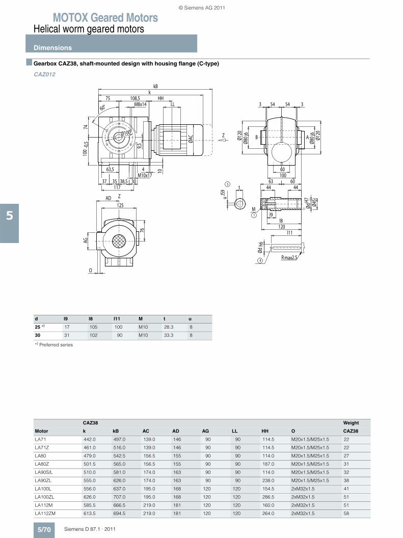
MOTOX Geared MotorsHelical worm geared motors
Dimensions
5/70 Siemens D 87.1 · 2011
5
■ Gearbox CAZ38, shaft-mounted design with housing flange (C-type)
CAZ012
d l9 l8 l11 M t u
25 *) 17 105 100 M10 28.3 8
30 31 102 90 M10 33.3 8
*) Preferred series
CAZ38 Weight
Motor k kB AC AD AG LL HH O CAZ38
LA71 442.0 497.0 139.0 146 90 90 114.5 M20x1.5/M25x1.5 22
LA71Z 461.0 516.0 139.0 146 90 90 114.5 M20x1.5/M25x1.5 22
LA80 479.0 542.5 156.5 155 90 90 114.0 M20x1.5/M25x1.5 27
LA80Z 501.5 565.0 156.5 155 90 90 187.0 M20x1.5/M25x1.5 31
LA90S/L 510.0 581.0 174.0 163 90 90 114.0 M20x1.5/M25x1.5 32
LA90ZL 555.0 626.0 174.0 163 90 90 238.0 M20x1.5/M25x1.5 38
LA100L 556.0 637.0 195.0 168 120 120 154.5 2xM32x1.5 41
LA100ZL 626.0 707.0 195.0 168 120 120 286.5 2xM32x1.5 51
LA112M 585.5 666.5 219.0 181 120 120 160.0 2xM32x1.5 51
LA112ZM 613.5 694.5 219.0 181 120 120 264.0 2xM32x1.5 58
Z
Z
max2.5R
5
1
M
4
AB
HH
AG
LL
35 38,5M10x17
54 54
Ø100
63,5
37 30
60
117
3360°
Ø80
j6
Ø80
j6
100
t
ØdH7
uJS
9
Ø45
Ødh6
l9
44 44
l8120
l11
63 60
10
O
76
AD125
Ø120
Ø120
4
7410
0-0
,5 ØAC
75 108,5M8x14
k
9,5
kB
© Siemens AG 2011
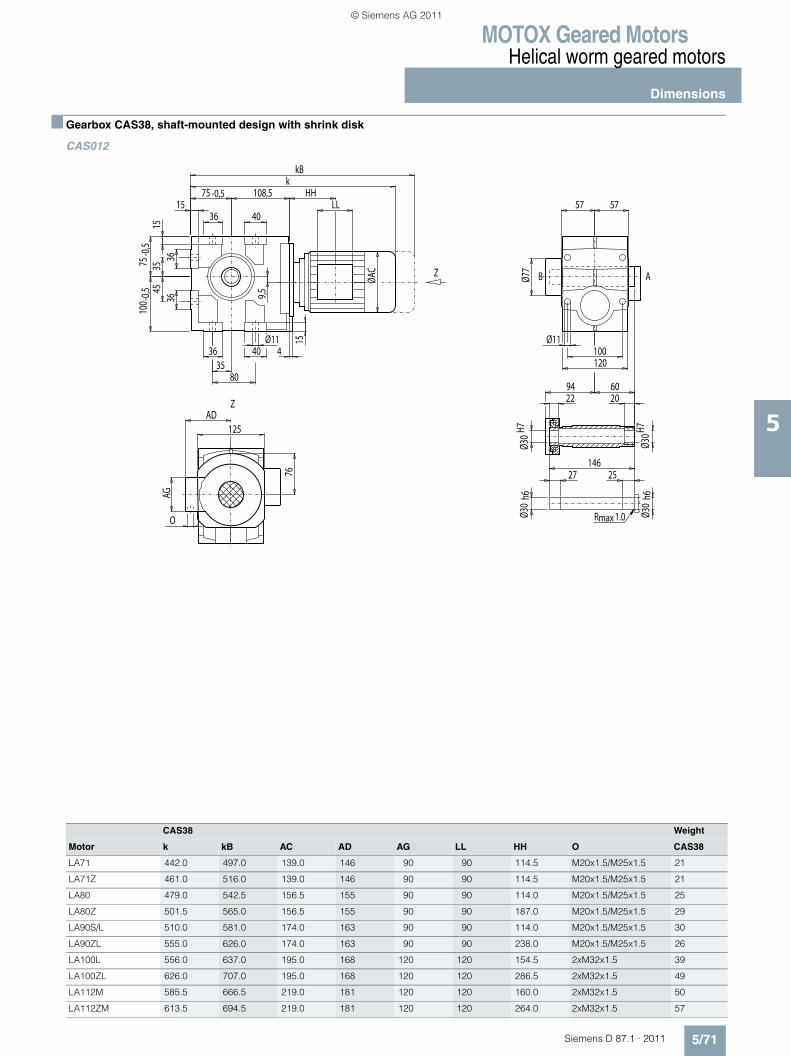
MOTOX Geared MotorsHelical worm geared motors
Dimensions
5/71Siemens D 87.1 · 2011
5
■ Gearbox CAS38, shaft-mounted design with shrink disk
CAS012
CAS38 Weight
Motor k kB AC AD AG LL HH O CAS38
LA71 442.0 497.0 139.0 146 90 90 114.5 M20x1.5/M25x1.5 21
LA71Z 461.0 516.0 139.0 146 90 90 114.5 M20x1.5/M25x1.5 21
LA80 479.0 542.5 156.5 155 90 90 114.0 M20x1.5/M25x1.5 25
LA80Z 501.5 565.0 156.5 155 90 90 187.0 M20x1.5/M25x1.5 29
LA90S/L 510.0 581.0 174.0 163 90 90 114.0 M20x1.5/M25x1.5 30
LA90ZL 555.0 626.0 174.0 163 90 90 238.0 M20x1.5/M25x1.5 26
LA100L 556.0 637.0 195.0 168 120 120 154.5 2xM32x1.5 39
LA100ZL 626.0 707.0 195.0 168 120 120 286.5 2xM32x1.5 49
LA112M 585.5 666.5 219.0 181 120 120 160.0 2xM32x1.5 50
LA112ZM 613.5 694.5 219.0 181 120 120 264.0 2xM32x1.5 57
Z
Z
maxR 1.0
AB
HH
AG
LL
Ø77
Ø30
h6Ø3
0H7
Ø30
H7
2294 60
20
14627 25
Ø30
h6
35
15
9,5
7615
4
80
O
125AD
Ø11
57 57
Ø11100120
3545
100 -
0,575
-0,5
36 40
1575 -0,5 108,5
kkB
ØAC
4036
3636
© Siemens AG 2011
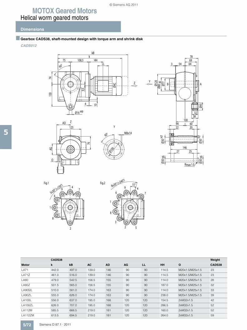
MOTOX Geared MotorsHelical worm geared motors
Dimensions
5/72 Siemens D 87.1 · 2011
5
■ Gearbox CADS38, shaft-mounted design with torque arm and shrink disk
CADS012
CADS38 Weight
Motor k kB AC AD AG LL HH O CADS38
LA71 442.0 497.0 139.0 146 90 90 114.5 M20x1.5/M25x1.5 23
LA71Z 461.0 516.0 139.0 146 90 90 114.5 M20x1.5/M25x1.5 23
LA80 479.0 542.5 156.5 155 90 90 114.0 M20x1.5/M25x1.5 28
LA80Z 501.5 565.0 156.5 155 90 90 187.0 M20x1.5/M25x1.5 32
LA90S/L 510.0 581.0 174.0 163 90 90 114.0 M20x1.5/M25x1.5 33
LA90ZL 555.0 626.0 174.0 163 90 90 238.0 M20x1.5/M25x1.5 39
LA100L 556.0 637.0 195.0 168 120 120 154.5 2xM32x1.5 42
LA100ZL 626.0 707.0 195.0 168 120 120 286.5 2xM32x1.5 52
LA112M 585.5 666.5 219.0 181 120 120 160.0 2xM32x1.5 52
LA112ZM 613.5 694.5 219.0 181 120 120 264.0 2xM32x1.5 59
2
4
6
8
1
79
Fig.1
2
46
8
Fig.2
1
3
5
7
9
maxR 1.0
ABY
Y
Z
Z
HH
M8x1460°
Ø100AG
LL
5x30° (=150°) 8x30° (=240°)
15°
7869
54
Ø77
Ø30
h6Ø3
0H7
Ø30
H7
2294 60
20
14627 25
Ø30
h6
Ø45
64
130
32Ø16 H938
360°
Ø80
j6
100
10
O
76
AD125
Ø120
4
74
ØAC
75 108,5k
9,5
kB
© Siemens AG 2011

MOTOX Geared MotorsHelical worm geared motors
Dimensions
5/73Siemens D 87.1 · 2011
5
■ Gearbox CAFS38, flange-mounted design and shrink disk
CAFS012
CAFS38 Weight
Motor k kB AC AD AG LL HH O CAFS38
LA71 442.0 497.0 139.0 146 90 90 114.5 M20x1.5/M25x1.5 24
LA71Z 461.0 516.0 139.0 146 90 90 114.5 M20x1.5/M25x1.5 24
LA80 479.0 542.5 156.5 155 90 90 114.0 M20x1.5/M25x1.5 29
LA80Z 501.5 565.0 156.5 155 90 90 187.0 M20x1.5/M25x1.5 33
LA90S/L 510.0 581.0 174.0 163 90 90 114.0 M20x1.5/M25x1.5 34
LA90ZL 555.0 626.0 174.0 163 90 90 238.0 M20x1.5/M25x1.5 40
LA100L 556.0 637.0 195.0 168 120 120 154.5 2xM32x1.5 43
LA100ZL 626.0 707.0 195.0 168 120 120 286.5 2xM32x1.5 53
LA112M 585.5 666.5 219.0 181 120 120 160.0 2xM32x1.5 53
LA112ZM 613.5 694.5 219.0 181 120 120 264.0 2xM32x1.5 60
Z
Z
maxR 1.0
AB
6
HH
AG
LL
35 38,5M10x17
Ø77
60
Ø30
h6Ø3
0H7
Ø30
H7
2294 60
20
14627 25
Ø30
h6
57 84
100
10
O
76
AD125
Ø110
j6Ø1
60
10 3,5
4
11737
63,5
30
7410
0 -0,5
ØAC
45°75 108,5
Ø9
kkB
9,5Ø130
➅ For note, see page 5/108
© Siemens AG 2011
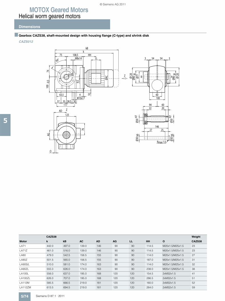
MOTOX Geared MotorsHelical worm geared motors
Dimensions
5/74 Siemens D 87.1 · 2011
5
■ Gearbox CAZS38, shaft-mounted design with housing flange (C-type) and shrink disk
CAZS012
CAZS38 Weight
Motor k kB AC AD AG LL HH O CAZS38
LA71 442.0 497.0 139.0 146 90 90 114.5 M20x1.5/M25x1.5 23
LA71Z 461.0 516.0 139.0 146 90 90 114.5 M20x1.5/M25x1.5 23
LA80 479.0 542.5 156.5 155 90 90 114.0 M20x1.5/M25x1.5 27
LA80Z 501.5 565.0 156.5 155 90 90 187.0 M20x1.5/M25x1.5 31
LA90S/L 510.0 581.0 174.0 163 90 90 114.0 M20x1.5/M25x1.5 32
LA90ZL 555.0 626.0 174.0 163 90 90 238.0 M20x1.5/M25x1.5 38
LA100L 556.0 637.0 195.0 168 120 120 154.5 2xM32x1.5 41
LA100ZL 626.0 707.0 195.0 168 120 120 286.5 2xM32x1.5 51
LA112M 585.5 666.5 219.0 181 120 120 160.0 2xM32x1.5 52
LA112ZM 613.5 694.5 219.0 181 120 120 264.0 2xM32x1.5 59
Z
Z
maxR 1.0
AB
AG
LLHH
35 38,5M10x17
54 54
Ø77
Ø30
H7Ø3
0h6
Ø30
H7
2294 60
20
14627 25
Ø30
h6
Ø100
63,5
37 30
60
117
3360°
Ø80
j6
Ø80
j6
100
10
O
76
AD125
Ø120
Ø120
4
7410
0-0
,5 ØAC
75 108,5M8x14
k
9,5
kB
© Siemens AG 2011

MOTOX Geared MotorsHelical worm geared motors
Dimensions
5/75Siemens D 87.1 · 2011
5
■ Gearbox C48, foot- and housing-flange-mounted designs (C-type)
C012
d to1 l l3 l4 t u i q DR
30 *) k6 60 50 3.5 33 8 80 135 M10x22
40 k6 80 70 5.0 43 12 100 155 M16x36
*) Preferred series
C48 Weight
Motor k kB AC AD AG LL HH O C48
LA71 459.5 514.5 139.0 146 90 90 114.5 M20x1.5/M25x1.5 30
LA71Z 478.5 533.5 139.0 146 90 90 114.5 M20x1.5/M25x1.5 30
LA80 496.5 560.0 156.5 155 90 90 114.0 M20x1.5/M25x1.5 34
LA80Z 519.0 582.5 156.5 155 90 90 187.0 M20x1.5/M25x1.5 38
LA90S/L 527.5 598.5 174.0 163 90 90 114.0 M20x1.5/M25x1.5 39
LA90ZL 572.5 643.5 174.0 163 90 90 238.0 M20x1.5/M25x1.5 45
LA100L 573.5 654.5 195.0 168 120 120 154.5 2xM32x1.5 48
LA100ZL 643.5 724.5 195.0 168 120 120 286.5 2xM32x1.5 58
LA112M 603.0 684.0 219.0 181 120 120 160.0 2xM32x1.5 59
LA112ZM 631.0 712.0 219.0 181 120 120 264.0 2xM32x1.5 66
X
X
Z
Z
4DR
AB
5
HH
AG
LL
Ødto
1
Ødto
1
45
15
21,5
l3 l4
7615
4
100
O
125AD
Ø11
l 71 71 lq q
Ø11110 i136
4555
112 -
0,580
-0,5
40 45
1580 -0,5 121
kkB
ØAC
4540
4040
u
t
➃ DIN 332 ➄ Feather key / keyway DIN 6885
© Siemens AG 2011
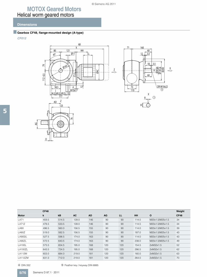
MOTOX Geared MotorsHelical worm geared motors
Dimensions
5/76 Siemens D 87.1 · 2011
5
■ Gearbox CF48, flange-mounted design (A-type)
CF012
A
4DR M10x22
5
X
X
Z
Z
HH
AG
LL
40,5 40,5M10x17
60
73110
12
O
76
AD125
50 3,5
Ø30 k
6Ø1
30j6
Ø200
71
12 3,560
160
4
11736,5
58,5
33
7911
2-0
,5 ØAC
45°80 121
Ø11
kkB
21,5
8
33
Ø165
CF48 Weight
Motor k kB AC AD AG LL HH O CF48
LA71 459.5 514.5 139.0 146 90 90 114.5 M20x1.5/M25x1.5 34
LA71Z 478.5 533.5 139.0 146 90 90 114.5 M20x1.5/M25x1.5 34
LA80 496.5 560.0 156.5 155 90 90 114.0 M20x1.5/M25x1.5 39
LA80Z 519.0 582.5 156.5 155 90 90 187.0 M20x1.5/M25x1.5 43
LA90S/L 527.5 598.5 174.0 163 90 90 114.0 M20x1.5/M25x1.5 43
LA90ZL 572.5 643.5 174.0 163 90 90 238.0 M20x1.5/M25x1.5 49
LA100L 573.5 654.5 195.0 168 120 120 154.5 2xM32x1.5 52
LA100ZL 643.5 724.5 195.0 168 120 120 286.5 2xM32x1.5 62
LA112M 603.0 684.0 219.0 181 120 120 160.0 2xM32x1.5 63
LA112ZM 631.0 712.0 219.0 181 120 120 264.0 2xM32x1.5 70
➃ DIN 332 ➄ Feather key / keyway DIN 6885
© Siemens AG 2011
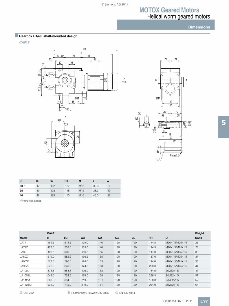
MOTOX Geared MotorsHelical worm geared motors
Dimensions
5/77Siemens D 87.1 · 2011
5
■ Gearbox CA48, shaft-mounted design
CA012
d l9 l8 l11 M t u
30 *) 17 132 127 M10 33.3 8
35 40 128 115 M12 38.3 10
40 48 128 115 M16 43.3 12
*) Preferred series
Z
Z
4
max2.5R
5
1
M
AB
HH
AG
LL
Ødh6
t
uJS
9
ØdH7 Ø5
5
l9
58 58
l8150
l11
78 75
45
15
21,5
76
15
4
100
O
125AD
Ø11
71 71
Ø11110136
4555
112 -
0,580
-0,5
40 45
1580 -0,5 121
kkB
ØAC
4540
4040
CA48 Weight
Motor k kB AC AD AG LL HH O CA48
LA71 459.5 514.5 139.0 146 90 90 114.5 M20x1.5/M25x1.5 28
LA71Z 478.5 533.5 139.0 146 90 90 114.5 M20x1.5/M25x1.5 28
LA80 496.5 560.0 156.5 155 90 90 114.0 M20x1.5/M25x1.5 33
LA80Z 519.0 582.5 156.5 155 90 90 187.0 M20x1.5/M25x1.5 37
LA90S/L 527.5 598.5 174.0 163 90 90 114.0 M20x1.5/M25x1.5 38
LA90ZL 572.5 643.5 174.0 163 90 90 238.0 M20x1.5/M25x1.5 44
LA100L 573.5 654.5 195.0 168 120 120 154.5 2xM32x1.5 47
LA100ZL 643.5 724.5 195.0 168 120 120 286.5 2xM32x1.5 57
LA112M 603.0 684.0 219.0 181 120 120 160.0 2xM32x1.5 57
LA112ZM 631.0 712.0 219.0 181 120 120 264.0 2xM32x1.5 64
➃ DIN 332 ➄ Feather key / keyway DIN 6885 ➀ EN ISO 4014
© Siemens AG 2011
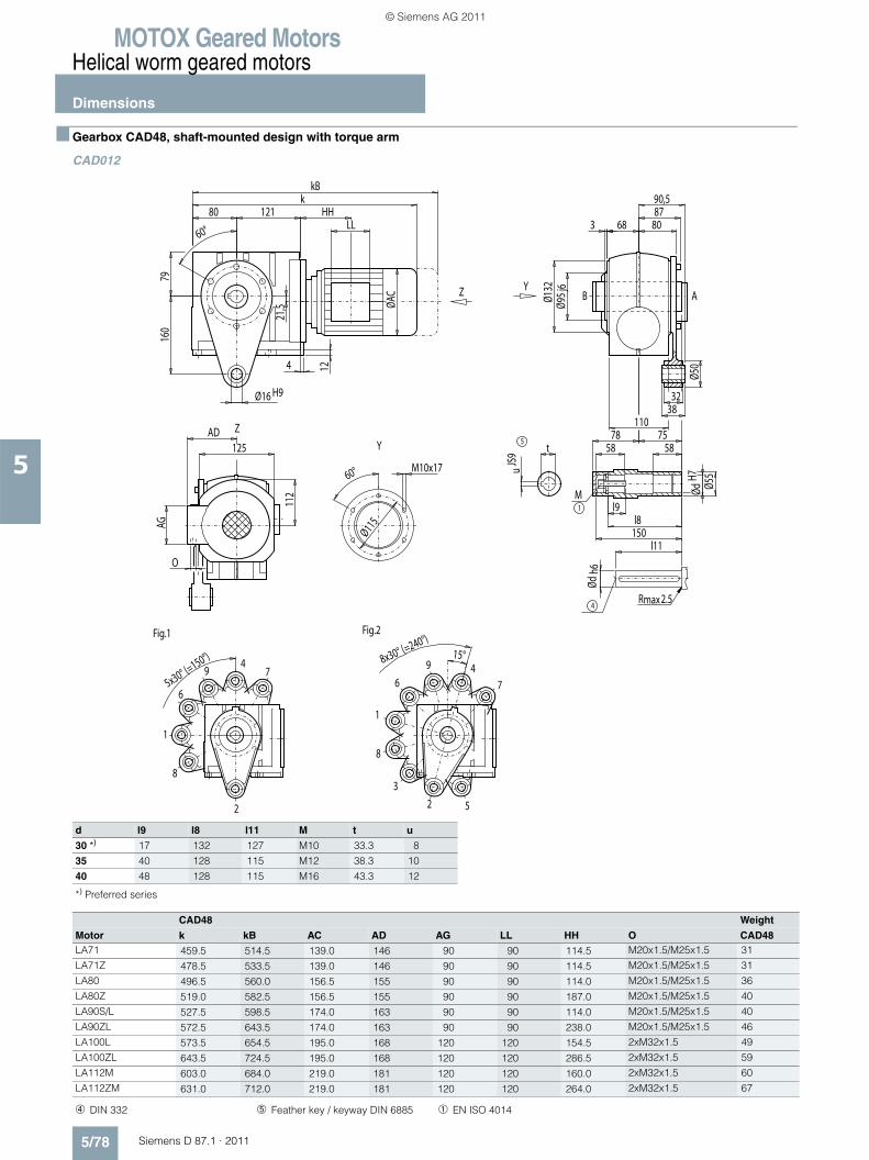
MOTOX Geared MotorsHelical worm geared motors
Dimensions
5/78 Siemens D 87.1 · 2011
5
■ Gearbox CAD48, shaft-mounted design with torque arm
CAD012
2
4
6
8
1
79
Fig.1
2
46
8
Fig.2
1
3
5
7
9
max2.5R
5
1
M
4
ABY
Y
Z
Z
HH
AG
LL
5x30° (=150°) 8x30° (=240°)
15°
90,5
68
Ødh6
ØdH7
Ø50
8087
160
32Ø16 H938
360°
Ø95 j
6
M10x1760°
Ø115
110
t
uJS
9
Ø55
l9
58 58
l8150
l11
78 75
12
O
112
AD125
Ø132
4
79
ØAC
80 121k
21,5
kB
d l9 l8 l11 M t u
30 *) 17 132 127 M10 33.3 8
35 40 128 115 M12 38.3 10
40 48 128 115 M16 43.3 12
*) Preferred series
CAD48 Weight
Motor k kB AC AD AG LL HH O CAD48LA71 459.5 514.5 139.0 146 90 90 114.5 M20x1.5/M25x1.5 31
LA71Z 478.5 533.5 139.0 146 90 90 114.5 M20x1.5/M25x1.5 31
LA80 496.5 560.0 156.5 155 90 90 114.0 M20x1.5/M25x1.5 36
LA80Z 519.0 582.5 156.5 155 90 90 187.0 M20x1.5/M25x1.5 40
LA90S/L 527.5 598.5 174.0 163 90 90 114.0 M20x1.5/M25x1.5 40
LA90ZL 572.5 643.5 174.0 163 90 90 238.0 M20x1.5/M25x1.5 46
LA100L 573.5 654.5 195.0 168 120 120 154.5 2xM32x1.5 49
LA100ZL 643.5 724.5 195.0 168 120 120 286.5 2xM32x1.5 59
LA112M 603.0 684.0 219.0 181 120 120 160.0 2xM32x1.5 60
LA112ZM 631.0 712.0 219.0 181 120 120 264.0 2xM32x1.5 67
➃ DIN 332 ➄ Feather key / keyway DIN 6885 ➀ EN ISO 4014
© Siemens AG 2011
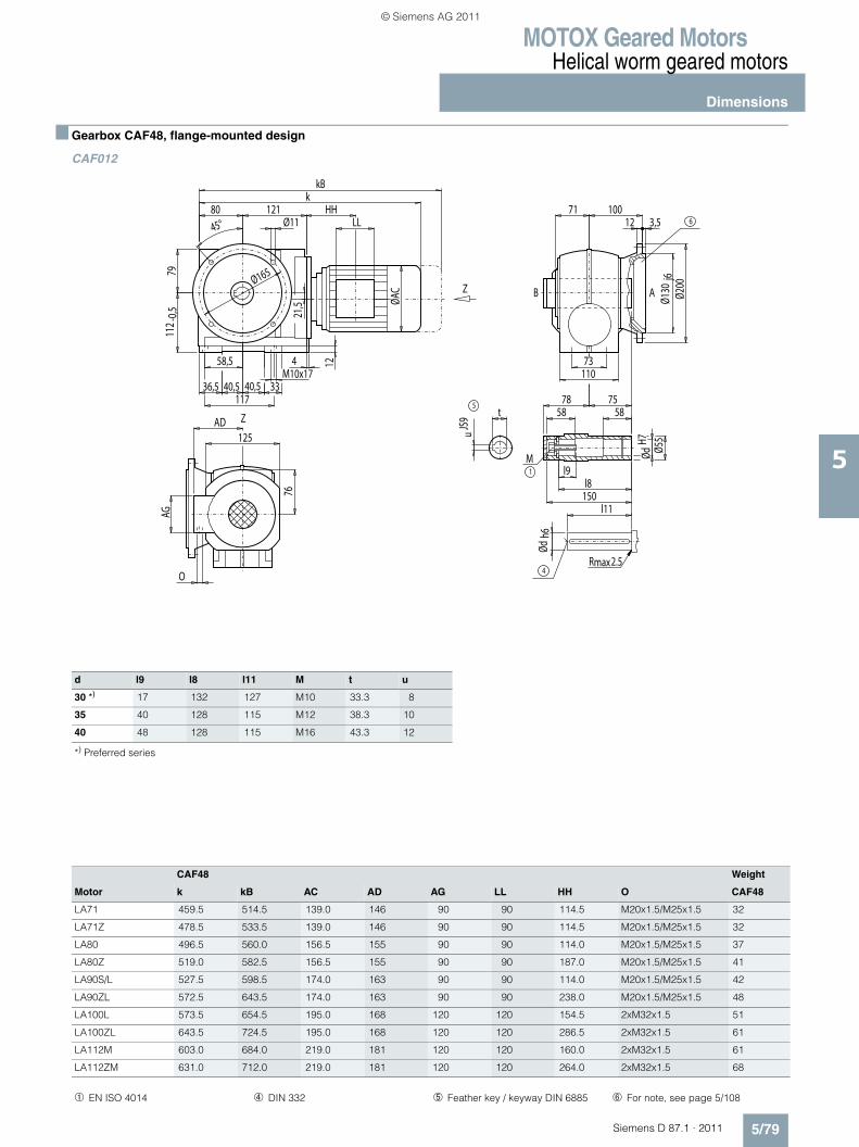
MOTOX Geared MotorsHelical worm geared motors
Dimensions
5/79Siemens D 87.1 · 2011
5
■ Gearbox CAF48, flange-mounted design
CAF012
Z
Z
max2.5R
5
1
M
4
AB
6HH
AG
LL
Ødh6
73
71 100
t
ØdH7
uJS
9
Ø55
l9
58 58
l8150
l11
78 75
110
12
O
76
AD125
Ø130
j6Ø2
00
12 3,5
M10x174
11736,5
58,5
3340,5 40,5
7911
2 -0,5
ØAC
45°80 121
Ø11
kkB
21,5
Ø165
d l9 l8 l11 M t u
30 *) 17 132 127 M10 33.3 8
35 40 128 115 M12 38.3 10
40 48 128 115 M16 43.3 12
*) Preferred series
CAF48 Weight
Motor k kB AC AD AG LL HH O CAF48
LA71 459.5 514.5 139.0 146 90 90 114.5 M20x1.5/M25x1.5 32
LA71Z 478.5 533.5 139.0 146 90 90 114.5 M20x1.5/M25x1.5 32
LA80 496.5 560.0 156.5 155 90 90 114.0 M20x1.5/M25x1.5 37
LA80Z 519.0 582.5 156.5 155 90 90 187.0 M20x1.5/M25x1.5 41
LA90S/L 527.5 598.5 174.0 163 90 90 114.0 M20x1.5/M25x1.5 42
LA90ZL 572.5 643.5 174.0 163 90 90 238.0 M20x1.5/M25x1.5 48
LA100L 573.5 654.5 195.0 168 120 120 154.5 2xM32x1.5 51
LA100ZL 643.5 724.5 195.0 168 120 120 286.5 2xM32x1.5 61
LA112M 603.0 684.0 219.0 181 120 120 160.0 2xM32x1.5 61
LA112ZM 631.0 712.0 219.0 181 120 120 264.0 2xM32x1.5 68
➀ EN ISO 4014 ➃ DIN 332 ➄ Feather key / keyway DIN 6885 ➅ For note, see page 5/108
© Siemens AG 2011
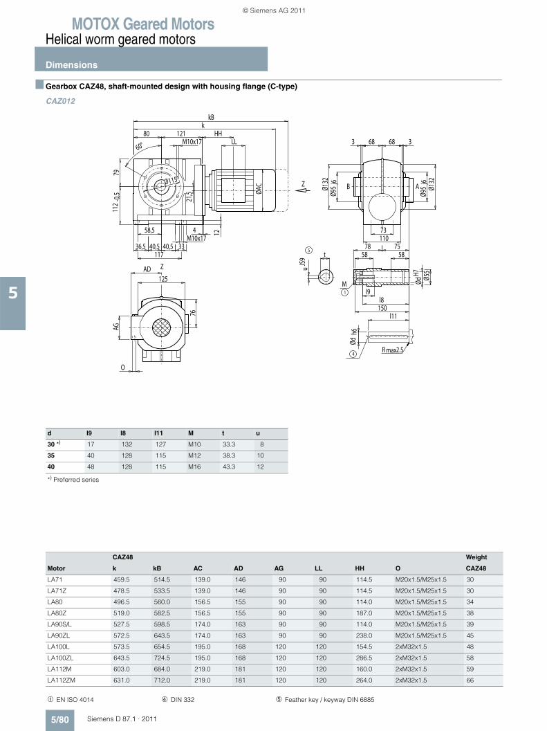
MOTOX Geared MotorsHelical worm geared motors
Dimensions
5/80 Siemens D 87.1 · 2011
5
■ Gearbox CAZ48, shaft-mounted design with housing flange (C-type)
CAZ012
d l9 l8 l11 M t u
30 *) 17 132 127 M10 33.3 8
35 40 128 115 M12 38.3 10
40 48 128 115 M16 43.3 12
*) Preferred series
CAZ48 Weight
Motor k kB AC AD AG LL HH O CAZ48
LA71 459.5 514.5 139.0 146 90 90 114.5 M20x1.5/M25x1.5 30
LA71Z 478.5 533.5 139.0 146 90 90 114.5 M20x1.5/M25x1.5 30
LA80 496.5 560.0 156.5 155 90 90 114.0 M20x1.5/M25x1.5 34
LA80Z 519.0 582.5 156.5 155 90 90 187.0 M20x1.5/M25x1.5 38
LA90S/L 527.5 598.5 174.0 163 90 90 114.0 M20x1.5/M25x1.5 39
LA90ZL 572.5 643.5 174.0 163 90 90 238.0 M20x1.5/M25x1.5 45
LA100L 573.5 654.5 195.0 168 120 120 154.5 2xM32x1.5 48
LA100ZL 643.5 724.5 195.0 168 120 120 286.5 2xM32x1.5 58
LA112M 603.0 684.0 219.0 181 120 120 160.0 2xM32x1.5 59
LA112ZM 631.0 712.0 219.0 181 120 120 264.0 2xM32x1.5 66
Z
Z
max2.5R
5
1
M
4
AB
HH
AG
LL
40,5 40,5M10x17
68 68
Ø115
58,5
36,5 33
73
117
3360°
Ø95
j6
Ø95
j6
110
t
ØdH7
uJS
9
Ø55
Ødh6
l9
58 58
l8150
l11
78 75
12
O
76
AD125
Ø132
Ø132
4
7911
2-0
,5 ØAC
80 121M10x17
k
21,5
kB
➀ EN ISO 4014 ➃ DIN 332 ➄ Feather key / keyway DIN 6885
© Siemens AG 2011
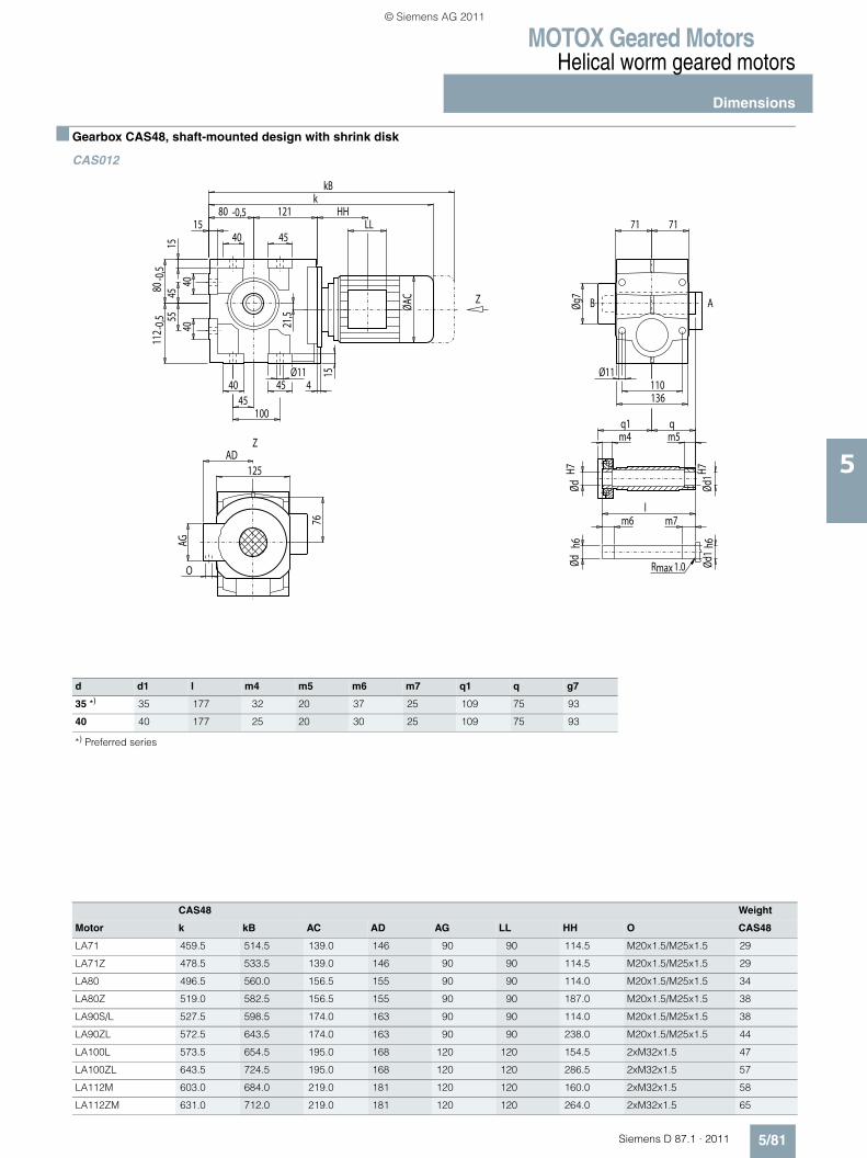
MOTOX Geared MotorsHelical worm geared motors
Dimensions
5/81Siemens D 87.1 · 2011
5
■ Gearbox CAS48, shaft-mounted design with shrink disk
CAS012
d d1 l m4 m5 m6 m7 q1 q g7
35 *) 35 177 32 20 37 25 109 75 93
40 40 177 25 20 30 25 109 75 93
*) Preferred series
CAS48 Weight
Motor k kB AC AD AG LL HH O CAS48
LA71 459.5 514.5 139.0 146 90 90 114.5 M20x1.5/M25x1.5 29
LA71Z 478.5 533.5 139.0 146 90 90 114.5 M20x1.5/M25x1.5 29
LA80 496.5 560.0 156.5 155 90 90 114.0 M20x1.5/M25x1.5 34
LA80Z 519.0 582.5 156.5 155 90 90 187.0 M20x1.5/M25x1.5 38
LA90S/L 527.5 598.5 174.0 163 90 90 114.0 M20x1.5/M25x1.5 38
LA90ZL 572.5 643.5 174.0 163 90 90 238.0 M20x1.5/M25x1.5 44
LA100L 573.5 654.5 195.0 168 120 120 154.5 2xM32x1.5 47
LA100ZL 643.5 724.5 195.0 168 120 120 286.5 2xM32x1.5 57
LA112M 603.0 684.0 219.0 181 120 120 160.0 2xM32x1.5 58
LA112ZM 631.0 712.0 219.0 181 120 120 264.0 2xM32x1.5 65
Z
Z
maxR 1.0
AB
HH
AG
LL
Øg7
Ød1
h6Ød
1H7
ØdH7
m4q1 q
m5
lm6 m7
Ødh6
45
15
21,5
7615
4
100
O
125AD
Ø11
71 71
Ø11110136
4555
112 -
0,580
-0,5
40 45
1580 -0,5 121
kkB
ØAC
4540
4040
© Siemens AG 2011
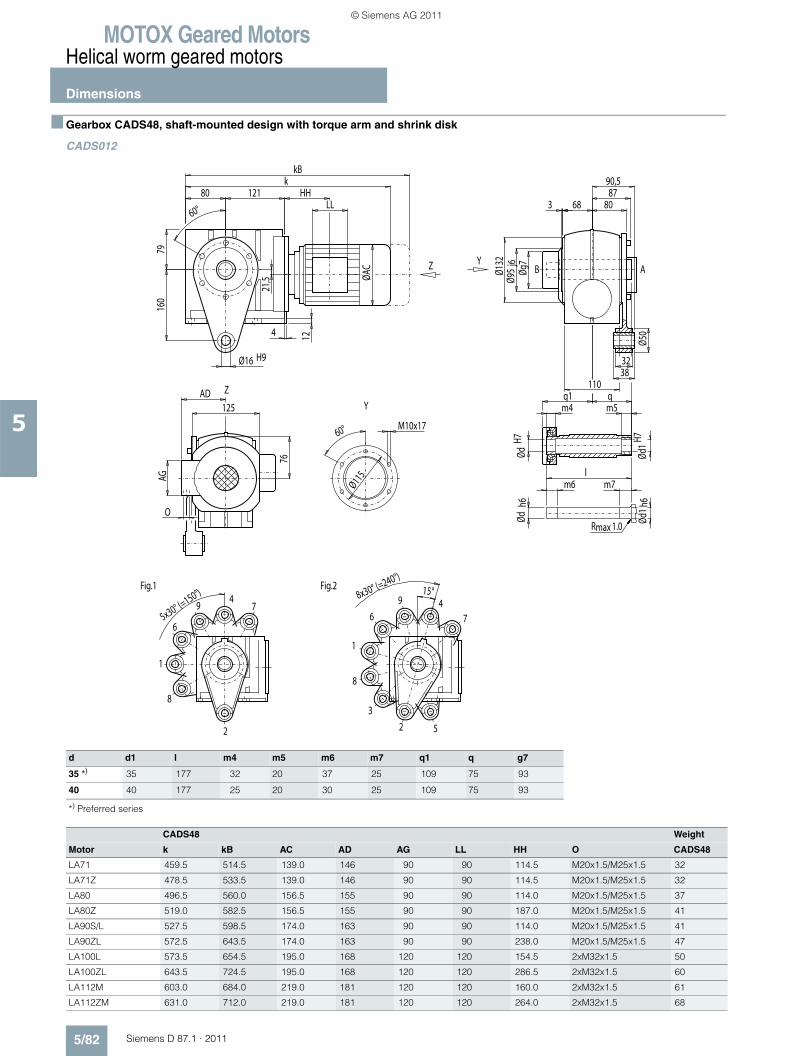
MOTOX Geared MotorsHelical worm geared motors
Dimensions
5/82 Siemens D 87.1 · 2011
5
■ Gearbox CADS48, shaft-mounted design with torque arm and shrink disk
CADS012
d d1 l m4 m5 m6 m7 q1 q g7
35 *) 35 177 32 20 37 25 109 75 93
40 40 177 25 20 30 25 109 75 93
*) Preferred series
CADS48 Weight
Motor k kB AC AD AG LL HH O CADS48
LA71 459.5 514.5 139.0 146 90 90 114.5 M20x1.5/M25x1.5 32
LA71Z 478.5 533.5 139.0 146 90 90 114.5 M20x1.5/M25x1.5 32
LA80 496.5 560.0 156.5 155 90 90 114.0 M20x1.5/M25x1.5 37
LA80Z 519.0 582.5 156.5 155 90 90 187.0 M20x1.5/M25x1.5 41
LA90S/L 527.5 598.5 174.0 163 90 90 114.0 M20x1.5/M25x1.5 41
LA90ZL 572.5 643.5 174.0 163 90 90 238.0 M20x1.5/M25x1.5 47
LA100L 573.5 654.5 195.0 168 120 120 154.5 2xM32x1.5 50
LA100ZL 643.5 724.5 195.0 168 120 120 286.5 2xM32x1.5 60
LA112M 603.0 684.0 219.0 181 120 120 160.0 2xM32x1.5 61
LA112ZM 631.0 712.0 219.0 181 120 120 264.0 2xM32x1.5 68
2
4
6
8
1
79
Fig.1
2
46
8
Fig.2
1
3
5
7
9
maxR 1.0
ABY
Y
Z
Z
HH
M10x1760°
Ø115AG
LL
5x30° (=150°) 8x30° (=240°)
15°
90,587
68
Øg7
Ød1 h
6Ød
1H7
ØdH7
m4q1 q
m5
lm6 m7
Ødh6
Ø50
80
160
32Ø16 H938
360°
Ø95
j6
110
12
O
76
AD125
Ø132
4
79
ØAC
80 121k
21,5
kB
© Siemens AG 2011
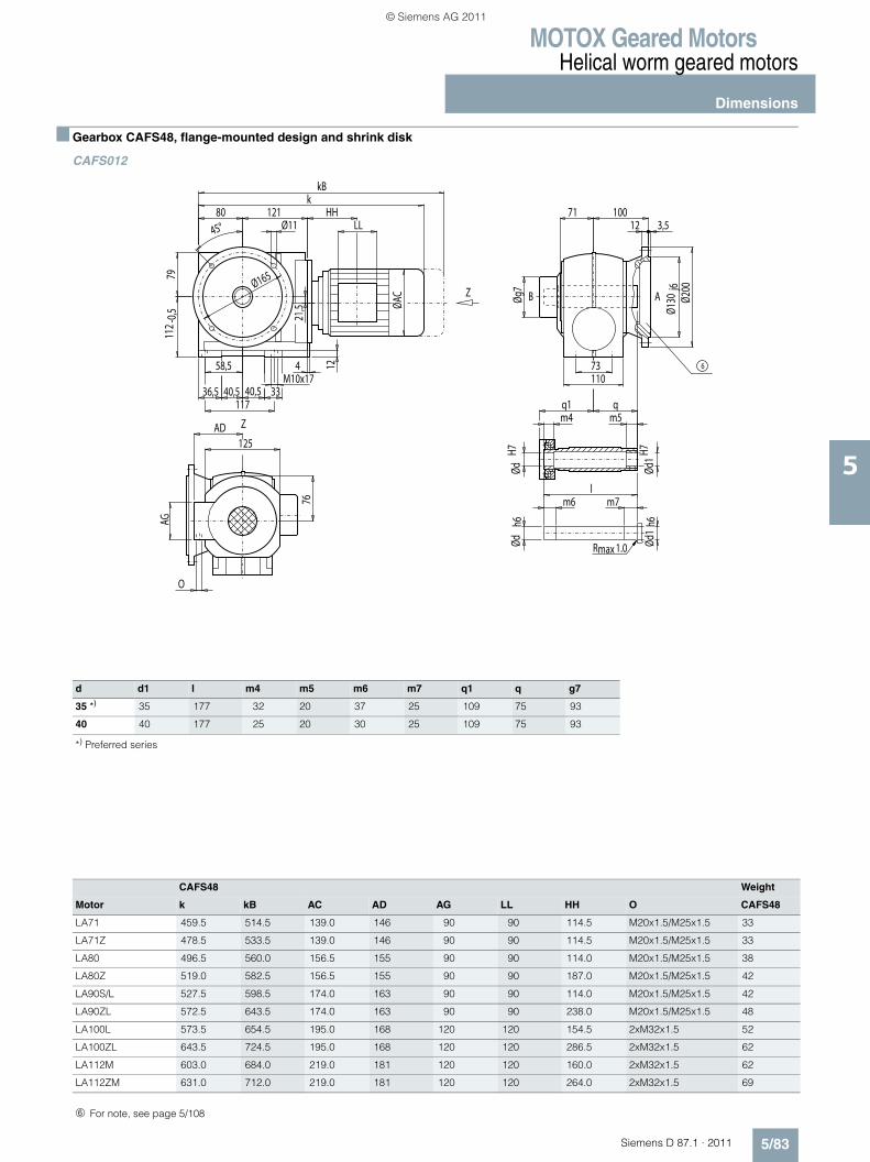
MOTOX Geared MotorsHelical worm geared motors
Dimensions
5/83Siemens D 87.1 · 2011
5
■ Gearbox CAFS48, flange-mounted design and shrink disk
CAFS012
Z
Z
maxR 1.0
AB
6
HH
AG
LL
40,5 40,5M10x17
Øg7
73
Ød1
h6Ød
1H7
ØdH7
m4q1 q
m5
lm6 m7
Ødh6
71 100
110
12
O
76
AD125
Ø130
j6Ø2
00
12 3,5
4
11736,5
58,5
33
7911
2 -0,5
ØAC
45°80 121
Ø11
kkB
21,5
Ø165
d d1 l m4 m5 m6 m7 q1 q g7
35 *) 35 177 32 20 37 25 109 75 93
40 40 177 25 20 30 25 109 75 93
*) Preferred series
CAFS48 Weight
Motor k kB AC AD AG LL HH O CAFS48
LA71 459.5 514.5 139.0 146 90 90 114.5 M20x1.5/M25x1.5 33
LA71Z 478.5 533.5 139.0 146 90 90 114.5 M20x1.5/M25x1.5 33
LA80 496.5 560.0 156.5 155 90 90 114.0 M20x1.5/M25x1.5 38
LA80Z 519.0 582.5 156.5 155 90 90 187.0 M20x1.5/M25x1.5 42
LA90S/L 527.5 598.5 174.0 163 90 90 114.0 M20x1.5/M25x1.5 42
LA90ZL 572.5 643.5 174.0 163 90 90 238.0 M20x1.5/M25x1.5 48
LA100L 573.5 654.5 195.0 168 120 120 154.5 2xM32x1.5 52
LA100ZL 643.5 724.5 195.0 168 120 120 286.5 2xM32x1.5 62
LA112M 603.0 684.0 219.0 181 120 120 160.0 2xM32x1.5 62
LA112ZM 631.0 712.0 219.0 181 120 120 264.0 2xM32x1.5 69
➅ For note, see page 5/108
© Siemens AG 2011
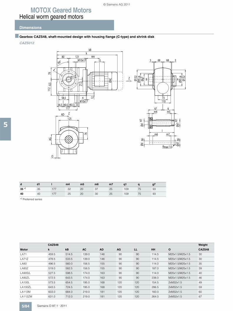
MOTOX Geared MotorsHelical worm geared motors
Dimensions
5/84 Siemens D 87.1 · 2011
5
■ Gearbox CAZS48, shaft-mounted design with housing flange (C-type) and shrink disk
CAZS012
Z
Z
maxR 1.0
AB
HH
AG
LL
40,5 40,5M10x17
68 68
Øg7
Ød1
H7Ød
1h6
ØdH7
m4q1 q
m5
lm6 m7
Ødh6
Ø115
58,5
36,5 33
73
117
3360°
Ø95
j6
Ø95
j6
110
12
O
76
AD125
Ø132
Ø132
4
7911
2-0
,5 ØAC
80 121M10x17
k
21,5
kB
d d1 l m4 m5 m6 m7 q1 q g7
35 *) 35 177 32 20 37 25 109 75 93
40 40 177 25 20 30 25 109 75 93
*) Preferred series
CAZS48 Weight
Motor k kB AC AD AG LL HH O CAZS48
LA71 459.5 514.5 139.0 146 90 90 114.5 M20x1.5/M25x1.5 30
LA71Z 478.5 533.5 139.0 146 90 90 114.5 M20x1.5/M25x1.5 30
LA80 496.5 560.0 156.5 155 90 90 114.0 M20x1.5/M25x1.5 35
LA80Z 519.0 582.5 156.5 155 90 90 187.0 M20x1.5/M25x1.5 39
LA90S/L 527.5 598.5 174.0 163 90 90 114.0 M20x1.5/M25x1.5 40
LA90ZL 572.5 643.5 174.0 163 90 90 238.0 M20x1.5/M25x1.5 46
LA100L 573.5 654.5 195.0 168 120 120 154.5 2xM32x1.5 49
LA100ZL 643.5 724.5 195.0 168 120 120 286.5 2xM32x1.5 59
LA112M 603.0 684.0 219.0 181 120 120 160.0 2xM32x1.5 60
LA112ZM 631.0 712.0 219.0 181 120 120 264.0 2xM32x1.5 67
© Siemens AG 2011

MOTOX Geared MotorsHelical worm geared motors
Dimensions
5/85Siemens D 87.1 · 2011
5
■ Gearbox C68, foot- and housing-flange-mounted designs (C-type)
C012
d to1 l l3 l4 t u i q DR
35 *) k6 70 56 5 38.0 10 95 160 M12x28
40 k6 80 70 5 43.0 12 105 170 M16x36
50 k6 100 80 10 53.5 14 125 190 M16x36
*) Preferred series
C68 Weight
Motor k kB AC AD AG LL HH O C68
LA71 504.0 559.0 139.0 146 90 90 109.0 M20x1.5/M25x1.5 46
LA71Z 523.0 578.0 139.0 146 90 90 109.0 M20x1.5/M25x1.5 46
LA80 541.0 604.5 156.5 155 90 90 108.5 M20x1.5/M25x1.5 51
LA80Z 563.5 627.0 156.5 155 90 90 181.5 M20x1.5/M25x1.5 55
LA90S/L 572.0 643.0 174.0 163 90 90 108.5 M20x1.5/M25x1.5 56
LA90ZL 617.0 688.0 174.0 163 90 90 232.5 M20x1.5/M25x1.5 62
LA100L 618.0 699.0 195.0 168 120 120 149.0 2xM32x1.5 65
LA100ZL 688.0 769.0 195.0 168 120 120 281.0 2xM32x1.5 75
LA112M 647.0 728.0 219.0 181 120 120 154.0 2xM32x1.5 76
LA112ZM 675.0 756.0 219.0 181 120 120 258.0 2xM32x1.5 83
LA132S/M 709.0 811.0 259.0 195 140 140 196.5 2xM32x1.5 86
LA132ZM 755.0 857.0 259.0 195 140 140 304.5 2xM32x1.5 107
X
X
Z
Z
4DR
AB
5
HH
AG
LL
150
Ødto
1
Ødto
1
60
18
31
l3 l4
9518
4
130
O
160AD
Ø13,5
l 86 86 lq q
Ø13,5130 i160
6070
140 -
0,510
6-0
,5
51 57
18106 -0,5 145
kkB
ØAC
5751
5051
u
t
➃ DIN 332 ➄ Feather key / keyway DIN 6885
© Siemens AG 2011
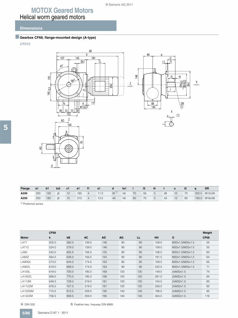
MOTOX Geared MotorsHelical worm geared motors
Dimensions
5/86 Siemens D 87.1 · 2011
5
■ Gearbox CF68, flange-mounted design (A-type)
CF012
Flange a1 b1 to2 c1 e1 f1 s1 d to1 l l3 l4 t u i2 q DR
A200 200 130 j6 12 165 4 11.0 35 *) k6 70 56 5 38 10 70 202.5 M12x28
A250 250 180 j6 15 215 4 13.5 40 k6 80 70 5 43 12 80 193.0 M16x36
*) Preferred series
4DR
5
X
X
Z
Z
HH
AG
53 53M12x21
l
88140
148
12
O
95
AD160
l3 l4
Ødto
1Øb
1to2
Øa1
86
c1 f1i2
q
4
15238
76
38
105
140 -
0,5
ØAC
45°
107 145Øs1
kkB
31
u
t
LL
Øe1
CF68 Weight
Motor k kB AC AD AG LL HH O CF68
LA71 505.0 560.0 139.0 146 90 90 109.0 M20x1.5/M25x1.5 55
LA71Z 524.0 579.0 139.0 146 90 90 109.0 M20x1.5/M25x1.5 55
LA80 542.0 605.5 156.5 155 90 90 108.5 M20x1.5/M25x1.5 60
LA80Z 564.5 628.0 156.5 155 90 90 181.5 M20x1.5/M25x1.5 64
LA90S/L 573.0 644.0 174.0 163 90 90 108.5 M20x1.5/M25x1.5 65
LA90ZL 618.0 689.0 174.0 163 90 90 232.5 M20x1.5/M25x1.5 71
LA100L 619.0 700.0 195.0 168 120 120 149.0 2xM32x1.5 74
LA100ZL 689.0 770.0 195.0 168 120 120 281.0 2xM32x1.5 84
LA112M 648.0 729.0 219.0 181 120 120 154.0 2xM32x1.5 85
LA112ZM 676.0 757.0 219.0 181 120 120 258.0 2xM32x1.5 92
LA132S/M 710.5 812.5 259.0 195 140 140 196.5 2xM32x1.5 95
LA132ZM 756.5 858.5 259.0 195 140 140 304.5 2xM32x1.5 116
➃ DIN 332 ➄ Feather key / keyway DIN 6885
© Siemens AG 2011
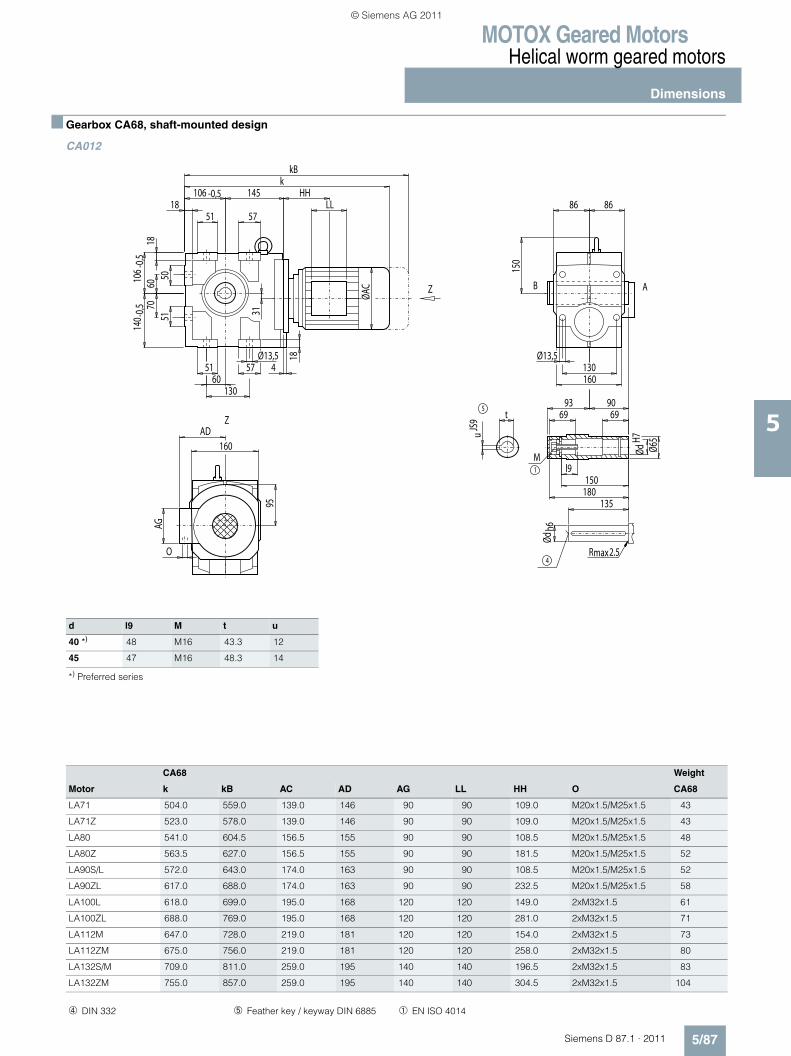
MOTOX Geared MotorsHelical worm geared motors
Dimensions
5/87Siemens D 87.1 · 2011
5
■ Gearbox CA68, shaft-mounted design
CA012
d l9 M t u
40 *) 48 M16 43.3 12
45 47 M16 48.3 14
*) Preferred series
Z
Z
4max2.5R
5
1
M
AB
HH
AG
LL
ØdH7
Ødh6
150
t
uJS
9
Ø65
l9
69 69
150180
135
93 90
60
18
3195
18
4
130
O
160AD
Ø13,5
86 86
Ø13,5130160
6070
140 -
0,510
6-0
,5
51 57
18106 -0,5 145
kkB
ØAC
5751
5051
CA68 Weight
Motor k kB AC AD AG LL HH O CA68
LA71 504.0 559.0 139.0 146 90 90 109.0 M20x1.5/M25x1.5 43
LA71Z 523.0 578.0 139.0 146 90 90 109.0 M20x1.5/M25x1.5 43
LA80 541.0 604.5 156.5 155 90 90 108.5 M20x1.5/M25x1.5 48
LA80Z 563.5 627.0 156.5 155 90 90 181.5 M20x1.5/M25x1.5 52
LA90S/L 572.0 643.0 174.0 163 90 90 108.5 M20x1.5/M25x1.5 52
LA90ZL 617.0 688.0 174.0 163 90 90 232.5 M20x1.5/M25x1.5 58
LA100L 618.0 699.0 195.0 168 120 120 149.0 2xM32x1.5 61
LA100ZL 688.0 769.0 195.0 168 120 120 281.0 2xM32x1.5 71
LA112M 647.0 728.0 219.0 181 120 120 154.0 2xM32x1.5 73
LA112ZM 675.0 756.0 219.0 181 120 120 258.0 2xM32x1.5 80
LA132S/M 709.0 811.0 259.0 195 140 140 196.5 2xM32x1.5 83
LA132ZM 755.0 857.0 259.0 195 140 140 304.5 2xM32x1.5 104
➃ DIN 332 ➄ Feather key / keyway DIN 6885 ➀ EN ISO 4014
© Siemens AG 2011
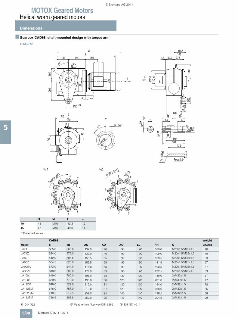
MOTOX Geared MotorsHelical worm geared motors
Dimensions
5/88 Siemens D 87.1 · 2011
5
■ Gearbox CAD68, shaft-mounted design with torque arm
CAD012
d l9 M t u
40 *) 48 M16 43.3 12
45 47 M16 48.3 14
*) Preferred series
2
4
6
8
1
3 5
79
Fig.1
2
46
8
Fig.2
1
3
5
7
9
max2.5R
5
1
M
4
ABY
Y
Z
Z
HH
M12x2160°
Ø130AG
LL
8x30° (=240°) 8x30° (=240°)
15°
97,5106106,5
82,5
Ø60
148
200
40Ø25 H946
3,5
60°
Ø110
j6
140
Ødh6
t
uJS
9
ØdH7
Ø65
l9
69 69
150180
135
93 90
12
O
95
AD160
Ø150
4
105
ØAC
107 145k
31
kB
CAD68 Weight
Motor k kB AC AD AG LL HH O CAD68
LA71 505.0 560.0 139.0 146 90 90 109.0 M20x1.5/M25x1.5 48
LA71Z 524.0 579.0 139.0 146 90 90 109.0 M20x1.5/M25x1.5 48
LA80 542.0 605.5 156.5 155 90 90 108.5 M20x1.5/M25x1.5 53
LA80Z 564.5 628.0 156.5 155 90 90 181.5 M20x1.5/M25x1.5 57
LA90S/L 573.0 644.0 174.0 163 90 90 108.5 M20x1.5/M25x1.5 57
LA90ZL 618.0 689.0 174.0 163 90 90 232.5 M20x1.5/M25x1.5 63
LA100L 619.0 700.0 195.0 168 120 120 149.0 2xM32x1.5 67
LA100ZL 689.0 770.0 195.0 168 120 120 281.0 2xM32x1.5 77
LA112M 648.0 729.0 219.0 181 120 120 154.0 2xM32x1.5 78
LA112ZM 676.0 757.0 219.0 181 120 120 258.0 2xM32x1.5 85
LA132S/M 710.5 812.5 259.0 195 140 140 196.5 2xM32x1.5 88
LA132ZM 756.5 858.5 259.0 195 140 140 304.5 2xM32x1.5 109
➃ DIN 332 ➄ Feather key / keyway DIN 6885 ➀ EN ISO 4014
© Siemens AG 2011
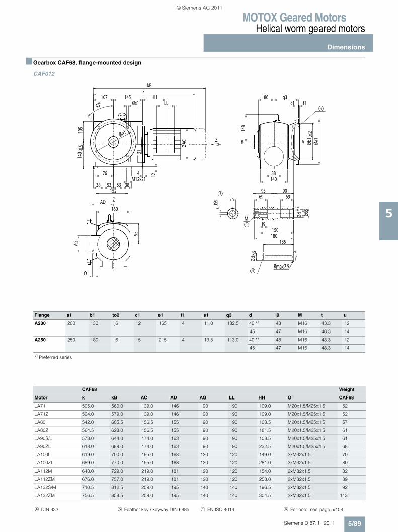
MOTOX Geared MotorsHelical worm geared motors
Dimensions
5/89Siemens D 87.1 · 2011
5
■ Gearbox CAF68, flange-mounted design
CAF012
Flange a1 b1 to2 c1 e1 f1 s1 q3 d l9 M t u
A200 200 130 j6 12 165 4 11.0 132.5 40 *) 48 M16 43.3 12
45 47 M16 48.3 14
A250 250 180 j6 15 215 4 13.5 113.0 40 *) 48 M16 43.3 12
45 47 M16 48.3 14
*) Preferred series
Z
Z
max2.5R
5
1
M
4
AB
6
HH
AG
M12x21
ØdH7
Øb1 t
o2
148
88
86 q3
t
uJS
9
Ø65
Ødh6
l9
69 69
150180
135
93 90
140
12
O
95
AD160
Øa1
c1 f1
4
15238
76
3853 53
105
140 -
0,5 ØAC
45°107 145
Øs1
kkB
31
LL
Øe1
CAF68 Weight
Motor k kB AC AD AG LL HH O CAF68
LA71 505.0 560.0 139.0 146 90 90 109.0 M20x1.5/M25x1.5 52
LA71Z 524.0 579.0 139.0 146 90 90 109.0 M20x1.5/M25x1.5 52
LA80 542.0 605.5 156.5 155 90 90 108.5 M20x1.5/M25x1.5 57
LA80Z 564.5 628.0 156.5 155 90 90 181.5 M20x1.5/M25x1.5 61
LA90S/L 573.0 644.0 174.0 163 90 90 108.5 M20x1.5/M25x1.5 61
LA90ZL 618.0 689.0 174.0 163 90 90 232.5 M20x1.5/M25x1.5 68
LA100L 619.0 700.0 195.0 168 120 120 149.0 2xM32x1.5 70
LA100ZL 689.0 770.0 195.0 168 120 120 281.0 2xM32x1.5 80
LA112M 648.0 729.0 219.0 181 120 120 154.0 2xM32x1.5 82
LA112ZM 676.0 757.0 219.0 181 120 120 258.0 2xM32x1.5 89
LA132S/M 710.5 812.5 259.0 195 140 140 196.5 2xM32x1.5 92
LA132ZM 756.5 858.5 259.0 195 140 140 304.5 2xM32x1.5 113
➃ DIN 332 ➄ Feather key / keyway DIN 6885 ➀ EN ISO 4014 ➅ For note, see page 5/108
© Siemens AG 2011
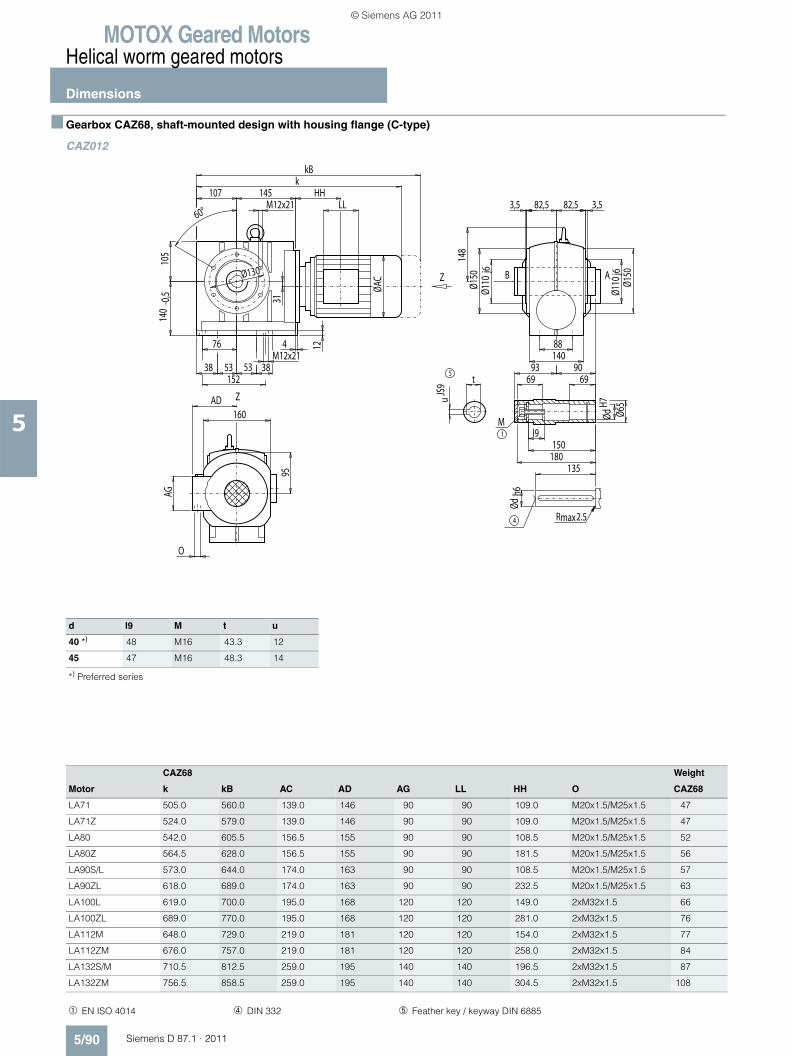
MOTOX Geared MotorsHelical worm geared motors
Dimensions
5/90 Siemens D 87.1 · 2011
5
■ Gearbox CAZ68, shaft-mounted design with housing flange (C-type)
CAZ012
d l9 M t u
40 *) 48 M16 43.3 12
45 47 M16 48.3 14
*) Preferred series
CAZ68 Weight
Motor k kB AC AD AG LL HH O CAZ68
LA71 505.0 560.0 139.0 146 90 90 109.0 M20x1.5/M25x1.5 47
LA71Z 524.0 579.0 139.0 146 90 90 109.0 M20x1.5/M25x1.5 47
LA80 542.0 605.5 156.5 155 90 90 108.5 M20x1.5/M25x1.5 52
LA80Z 564.5 628.0 156.5 155 90 90 181.5 M20x1.5/M25x1.5 56
LA90S/L 573.0 644.0 174.0 163 90 90 108.5 M20x1.5/M25x1.5 57
LA90ZL 618.0 689.0 174.0 163 90 90 232.5 M20x1.5/M25x1.5 63
LA100L 619.0 700.0 195.0 168 120 120 149.0 2xM32x1.5 66
LA100ZL 689.0 770.0 195.0 168 120 120 281.0 2xM32x1.5 76
LA112M 648.0 729.0 219.0 181 120 120 154.0 2xM32x1.5 77
LA112ZM 676.0 757.0 219.0 181 120 120 258.0 2xM32x1.5 84
LA132S/M 710.5 812.5 259.0 195 140 140 196.5 2xM32x1.5 87
LA132ZM 756.5 858.5 259.0 195 140 140 304.5 2xM32x1.5 108
➀ EN ISO 4014 ➃ DIN 332 ➄ Feather key / keyway DIN 6885
Z
Z
max2.5R
5
1
M
4
AB
HH
AG
LL
53 53M12x21
82,5 82,5
148
Ø130
76
38 38
88
152
3,53,560°
Ø110
j6
Ø110
j6
140
Ødh6
t
uJS
9
ØdH7
Ø65
l9
69 69
150180
135
93 90
12
O
95
AD160
Ø150
Ø150
4
105
140
M12x21
-0,5 ØA
C
107 145k
31
kB
© Siemens AG 2011
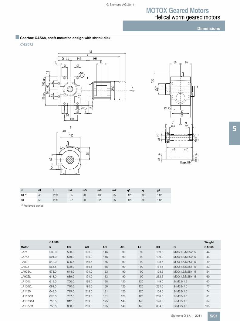
MOTOX Geared MotorsHelical worm geared motors
Dimensions
5/91Siemens D 87.1 · 2011
5
■ Gearbox CAS68, shaft-mounted design with shrink disk
CAS012
d d1 l m4 m5 m6 m7 q1 q g7
40 *) 40 209 35 20 40 25 126 90 112
50 50 209 27 20 32 25 126 90 112
*) Preferred series
CAS68 Weight
Motor k kB AC AD AG LL HH O CAS68
LA71 505.0 560.0 139.0 146 90 90 109.0 M20x1.5/M25x1.5 44
LA71Z 524.0 579.0 139.0 146 90 90 109.0 M20x1.5/M25x1.5 44
LA80 542.0 605.5 156.5 155 90 90 108.5 M20x1.5/M25x1.5 49
LA80Z 564.5 628.0 156.5 155 90 90 181.5 M20x1.5/M25x1.5 53
LA90S/L 573.0 644.0 174.0 163 90 90 108.5 M20x1.5/M25x1.5 54
LA90ZL 618.0 689.0 174.0 163 90 90 232.5 M20x1.5/M25x1.5 60
LA100L 619.0 700.0 195.0 168 120 120 149.0 2xM32x1.5 63
LA100ZL 689.0 770.0 195.0 168 120 120 281.0 2xM32x1.5 73
LA112M 648.0 729.0 219.0 181 120 120 154.0 2xM32x1.5 74
LA112ZM 676.0 757.0 219.0 181 120 120 258.0 2xM32x1.5 81
LA132S/M 710.5 812.5 259.0 195 140 140 196.5 2xM32x1.5 84
LA132ZM 756.5 858.5 259.0 195 140 140 304.5 2xM32x1.5 105
Z
Z
maxR 1.0
AB
HH
AG
LL
Øg7
150
Ød1
h6Ød
1H7
ØdH7
m4q1 q
m5
lm6 m7
Ødh6
60
18
31
9518
4
130
O
160AD
Ø13,5
86 86
Ø13,5130160
6070
140 -
0,510
6-0
,5
51 57
18106 -0,5 145
kkB
ØAC
5751
5051
© Siemens AG 2011
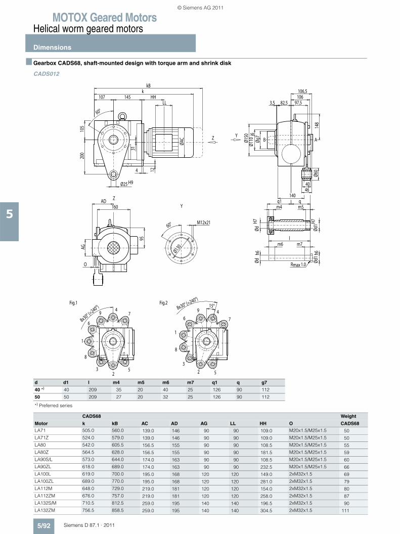
MOTOX Geared MotorsHelical worm geared motors
Dimensions
5/92 Siemens D 87.1 · 2011
5
■ Gearbox CADS68, shaft-mounted design with torque arm and shrink disk
CADS012
d d1 l m4 m5 m6 m7 q1 q g7
40 *) 40 209 35 20 40 25 126 90 112
50 50 209 27 20 32 25 126 90 112
*) Preferred series
CADS68 Weight
Motor k kB AC AD AG LL HH O CADS68LA71 505.0 560.0 139.0 146 90 90 109.0 M20x1.5/M25x1.5 50LA71Z 524.0 579.0 139.0 146 90 90 109.0 M20x1.5/M25x1.5 50LA80 542.0 605.5 156.5 155 90 90 108.5 M20x1.5/M25x1.5 55LA80Z 564.5 628.0 156.5 155 90 90 181.5 M20x1.5/M25x1.5 59LA90S/L 573.0 644.0 174.0 163 90 90 108.5 M20x1.5/M25x1.5 60LA90ZL 618.0 689.0 174.0 163 90 90 232.5 M20x1.5/M25x1.5 66LA100L 619.0 700.0 195.0 168 120 120 149.0 2xM32x1.5 69LA100ZL 689.0 770.0 195.0 168 120 120 281.0 2xM32x1.5 79LA112M 648.0 729.0 219.0 181 120 120 154.0 2xM32x1.5 80LA112ZM 676.0 757.0 219.0 181 120 120 258.0 2xM32x1.5 87LA132S/M 710.5 812.5 259.0 195 140 140 196.5 2xM32x1.5 90LA132ZM 756.5 858.5 259.0 195 140 140 304.5 2xM32x1.5 111
2
4
6
8
1
3 5
79
Fig.1
2
46
8
Fig.2
1
3
5
7
9
maxR 1.0
ABY
Y
Z
Z
HH
M12x2160°
Ø130AG
LL
8x30° (=240°) 8x30° (=240°)
15°
106,5106
97,582,5
148
Øg7
Ød1 h
6Ød
1H7
ØdH7
m4q1 q
m5
lm6 m7
Ødh6
Ø60
200
40Ø25 H946
3,5
60°
Ø110
j6
140
12
O
95
AD160
Ø150
4
105
ØAC
107 145k
31
kB
© Siemens AG 2011
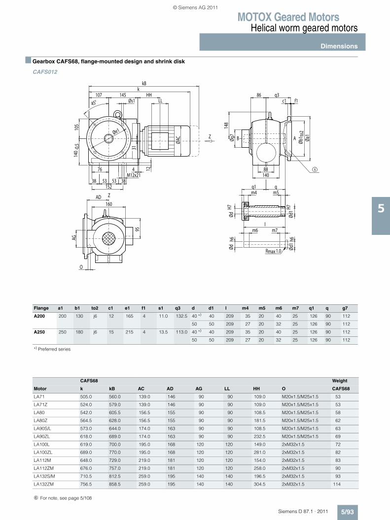
MOTOX Geared MotorsHelical worm geared motors
Dimensions
5/93Siemens D 87.1 · 2011
5
■ Gearbox CAFS68, flange-mounted design and shrink disk
CAFS012
Flange a1 b1 to2 c1 e1 f1 s1 q3 d d1 l m4 m5 m6 m7 q1 q g7
A200 200 130 j6 12 165 4 11.0 132.5 40 *) 40 209 35 20 40 25 126 90 112
50 50 209 27 20 32 25 126 90 112
A250 250 180 j6 15 215 4 13.5 113.0 40 *) 40 209 35 20 40 25 126 90 112
50 50 209 27 20 32 25 126 90 112
*) Preferred series
CAFS68 Weight
Motor k kB AC AD AG LL HH O CAFS68
LA71 505.0 560.0 139.0 146 90 90 109.0 M20x1.5/M25x1.5 53
LA71Z 524.0 579.0 139.0 146 90 90 109.0 M20x1.5/M25x1.5 53
LA80 542.0 605.5 156.5 155 90 90 108.5 M20x1.5/M25x1.5 58
LA80Z 564.5 628.0 156.5 155 90 90 181.5 M20x1.5/M25x1.5 62
LA90S/L 573.0 644.0 174.0 163 90 90 108.5 M20x1.5/M25x1.5 63
LA90ZL 618.0 689.0 174.0 163 90 90 232.5 M20x1.5/M25x1.5 69
LA100L 619.0 700.0 195.0 168 120 120 149.0 2xM32x1.5 72
LA100ZL 689.0 770.0 195.0 168 120 120 281.0 2xM32x1.5 82
LA112M 648.0 729.0 219.0 181 120 120 154.0 2xM32x1.5 83
LA112ZM 676.0 757.0 219.0 181 120 120 258.0 2xM32x1.5 90
LA132S/M 710.5 812.5 259.0 195 140 140 196.5 2xM32x1.5 93
LA132ZM 756.5 858.5 259.0 195 140 140 304.5 2xM32x1.5 114
Z
Z
maxR 1.0
AB
6
HH
AG
LL
148
Øg7
88
Ød1
h6Ød
1H7
ØdH7
m4q1 q
m5
lm6 m7
Ødh6
86 q3
140
12
O
95
AD160
Øb1 t
o2Øa
1
c1 f1
4
15238
76
53 53M12x21
38
105
140 -
0,5
ØAC
45°107 145
Øs1
kkB
31Øe1
➅ For note, see page 5/108
© Siemens AG 2011
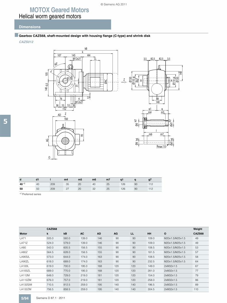
MOTOX Geared MotorsHelical worm geared motors
Dimensions
5/94 Siemens D 87.1 · 2011
5
■ Gearbox CAZS68, shaft-mounted design with housing flange (C-type) and shrink disk
CAZS012
d d1 l m4 m5 m6 m7 q1 q g7
40 *) 40 209 35 20 40 25 126 90 112
50 50 209 27 20 32 25 126 90 112
*) Preferred series
CAZS68 Weight
Motor k kB AC AD AG LL HH O CAZS68
LA71 505.0 560.0 139.0 146 90 90 109.0 M20x1.5/M25x1.5 49
LA71Z 524.0 579.0 139.0 146 90 90 109.0 M20x1.5/M25x1.5 49
LA80 542.0 605.5 156.5 155 90 90 108.5 M20x1.5/M25x1.5 53
LA80Z 564.5 628.0 156.5 155 90 90 181.5 M20x1.5/M25x1.5 57
LA90S/L 573.0 644.0 174.0 163 90 90 108.5 M20x1.5/M25x1.5 58
LA90ZL 618.0 689.0 174.0 163 90 90 232.5 M20x1.5/M25x1.5 64
LA100L 619.0 700.0 195.0 168 120 120 149.0 2xM32x1.5 67
LA100ZL 689.0 770.0 195.0 168 120 120 281.0 2xM32x1.5 77
LA112M 648.0 729.0 219.0 181 120 120 154.0 2xM32x1.5 79
LA112ZM 676.0 757.0 219.0 181 120 120 258.0 2xM32x1.5 86
LA132S/M 710.5 812.5 259.0 195 140 140 196.5 2xM32x1.5 89
LA132ZM 756.5 858.5 259.0 195 140 140 304.5 2xM32x1.5 110
Z
Z
maxR 1.0
AB
HH
AG
LL
53 53M12x21
82,5 82,5
Øg7
148
Ød1H7
Ød1 h
6
ØdH7
m4q1 q
m5
lm6 m7
Ødh6
Ø130
76
38 38
88
152
3,53,5
60°
Ø110
j6
Ø110
j6
140
12
O
95
AD160
Ø150
Ø150
4
105
140 -
0,5
ØAC
107 145M12x21
k
31
kB
© Siemens AG 2011
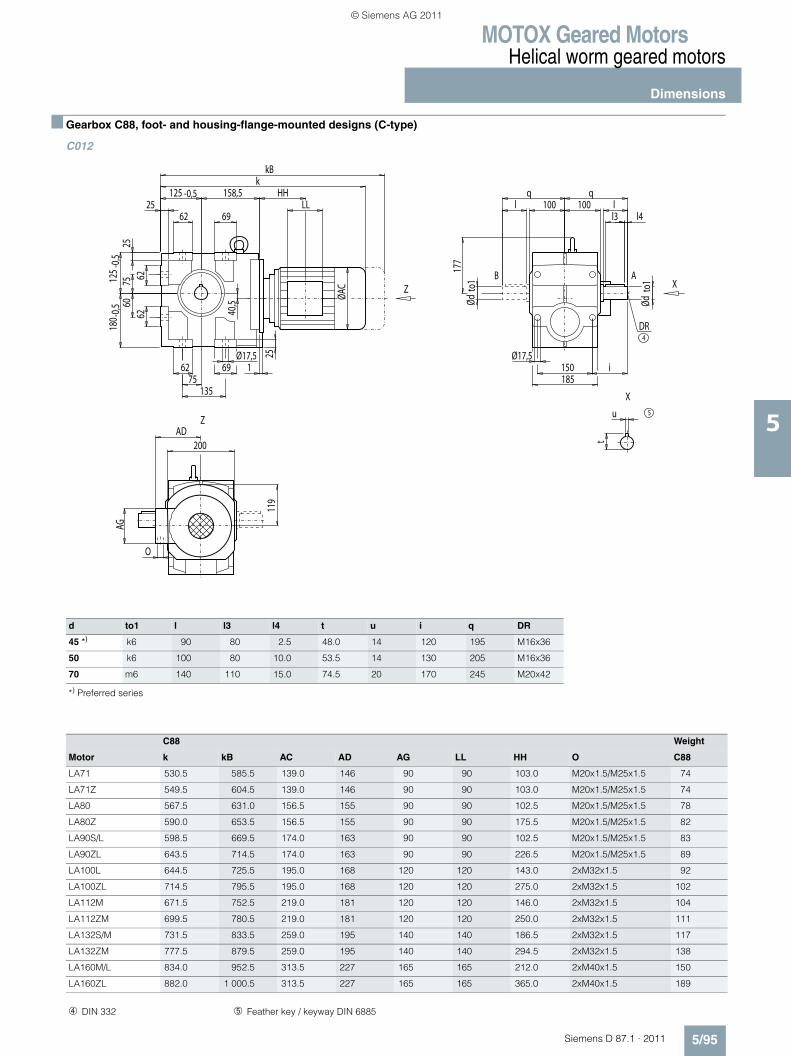
MOTOX Geared MotorsHelical worm geared motors
Dimensions
5/95Siemens D 87.1 · 2011
5
■ Gearbox C88, foot- and housing-flange-mounted designs (C-type)
C012
d to1 l l3 l4 t u i q DR
45 *) k6 90 80 2.5 48.0 14 120 195 M16x36
50 k6 100 80 10.0 53.5 14 130 205 M16x36
70 m6 140 110 15.0 74.5 20 170 245 M20x42
*) Preferred series
C88 Weight
Motor k kB AC AD AG LL HH O C88
LA71 530.5 585.5 139.0 146 90 90 103.0 M20x1.5/M25x1.5 74
LA71Z 549.5 604.5 139.0 146 90 90 103.0 M20x1.5/M25x1.5 74
LA80 567.5 631.0 156.5 155 90 90 102.5 M20x1.5/M25x1.5 78
LA80Z 590.0 653.5 156.5 155 90 90 175.5 M20x1.5/M25x1.5 82
LA90S/L 598.5 669.5 174.0 163 90 90 102.5 M20x1.5/M25x1.5 83
LA90ZL 643.5 714.5 174.0 163 90 90 226.5 M20x1.5/M25x1.5 89
LA100L 644.5 725.5 195.0 168 120 120 143.0 2xM32x1.5 92
LA100ZL 714.5 795.5 195.0 168 120 120 275.0 2xM32x1.5 102
LA112M 671.5 752.5 219.0 181 120 120 146.0 2xM32x1.5 104
LA112ZM 699.5 780.5 219.0 181 120 120 250.0 2xM32x1.5 111
LA132S/M 731.5 833.5 259.0 195 140 140 186.5 2xM32x1.5 117
LA132ZM 777.5 879.5 259.0 195 140 140 294.5 2xM32x1.5 138
LA160M/L 834.0 952.5 313.5 227 165 165 212.0 2xM40x1.5 150
LA160ZL 882.0 1 000.5 313.5 227 165 165 365.0 2xM40x1.5 189
X
X
Z
Z
4DR
AB
5
HH
AG
LL
177
Ødto
1
Ødto
1
75
25
40,5
l3 l4
119
25
1
135
O
200AD
Ø17,5
l 100 100 lq q
Ø17,5150 i185
7560
180 -
0,512
5-0
,5
62 69
25125 -0,5 158,5
kkB
ØAC
6962
6262
u
t
➃ DIN 332 ➄ Feather key / keyway DIN 6885
© Siemens AG 2011
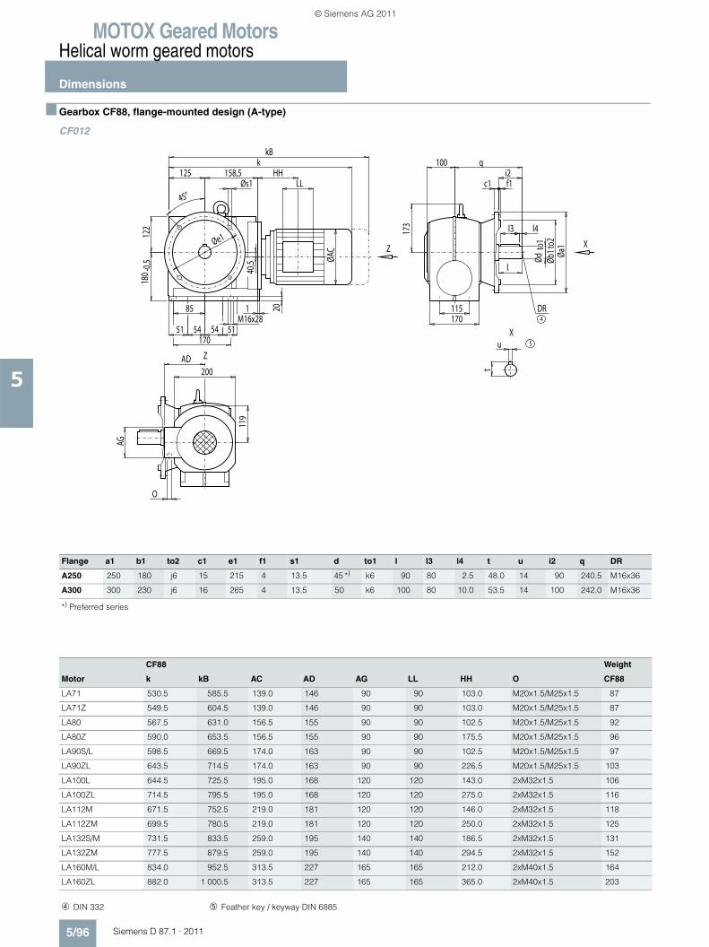
MOTOX Geared MotorsHelical worm geared motors
Dimensions
5/96 Siemens D 87.1 · 2011
5
■ Gearbox CF88, flange-mounted design (A-type)
CF012
Flange a1 b1 to2 c1 e1 f1 s1 d to1 l l3 l4 t u i2 q DR
A250 250 180 j6 15 215 4 13.5 45 *) k6 90 80 2.5 48.0 14 90 240.5 M16x36
A300 300 230 j6 16 265 4 13.5 50 k6 100 80 10.0 53.5 14 100 242.0 M16x36
*) Preferred series
4DR
5
X
X
Z
Z
HH
AG
54 54M16x28
l
115170
173
20
O
119
AD200
l3 l4
Ødto
1Øb
1to2
Øa1
100
c1 f1i2
q
1
17051
85
51
122
180 -
0,5
ØAC
45°
125 158,5Øs1
kkB
40,5
u
t
LL
Øe1
CF88 Weight
Motor k kB AC AD AG LL HH O CF88
LA71 530.5 585.5 139.0 146 90 90 103.0 M20x1.5/M25x1.5 87
LA71Z 549.5 604.5 139.0 146 90 90 103.0 M20x1.5/M25x1.5 87
LA80 567.5 631.0 156.5 155 90 90 102.5 M20x1.5/M25x1.5 92
LA80Z 590.0 653.5 156.5 155 90 90 175.5 M20x1.5/M25x1.5 96
LA90S/L 598.5 669.5 174.0 163 90 90 102.5 M20x1.5/M25x1.5 97
LA90ZL 643.5 714.5 174.0 163 90 90 226.5 M20x1.5/M25x1.5 103
LA100L 644.5 725.5 195.0 168 120 120 143.0 2xM32x1.5 106
LA100ZL 714.5 795.5 195.0 168 120 120 275.0 2xM32x1.5 116
LA112M 671.5 752.5 219.0 181 120 120 146.0 2xM32x1.5 118
LA112ZM 699.5 780.5 219.0 181 120 120 250.0 2xM32x1.5 125
LA132S/M 731.5 833.5 259.0 195 140 140 186.5 2xM32x1.5 131
LA132ZM 777.5 879.5 259.0 195 140 140 294.5 2xM32x1.5 152
LA160M/L 834.0 952.5 313.5 227 165 165 212.0 2xM40x1.5 164
LA160ZL 882.0 1 000.5 313.5 227 165 165 365.0 2xM40x1.5 203
➃ DIN 332 ➄ Feather key / keyway DIN 6885
© Siemens AG 2011
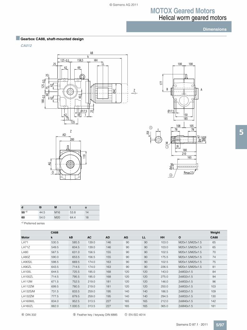
MOTOX Geared MotorsHelical worm geared motors
Dimensions
5/97Siemens D 87.1 · 2011
5
■ Gearbox CA88, shaft-mounted design
CA012
d l9 M t u
50 *) 44.5 M16 53.8 14
60 54.0 M20 64.4 18
*) Preferred series
Z
Z
4max2.5R
5
1
M
AB
HH
AG
LL
ØdH7
Ødh6
177
t
uJS
9
Ø80
l9
78 78
180210
165
108 105
75
25
40,5
119
25
1
135
O
200AD
Ø17,5
100 100
Ø17,5150185
7560
180 -
0,512
5-0
,5
62 69
25125 -0,5 158,5
kkB
ØAC
6962
6262
CA88 Weight
Motor k kB AC AD AG LL HH O CA88
LA71 530.5 585.5 139.0 146 90 90 103.0 M20x1.5/M25x1.5 65
LA71Z 549.5 604.5 139.0 146 90 90 103.0 M20x1.5/M25x1.5 65
LA80 567.5 631.0 156.5 155 90 90 102.5 M20x1.5/M25x1.5 70
LA80Z 590.0 653.5 156.5 155 90 90 175.5 M20x1.5/M25x1.5 74
LA90S/L 598.5 669.5 174.0 163 90 90 102.5 M20x1.5/M25x1.5 75
LA90ZL 643.5 714.5 174.0 163 90 90 226.5 M20x1.5/M25x1.5 81
LA100L 644.5 725.5 195.0 168 120 120 143.0 2xM32x1.5 84
LA100ZL 714.5 795.5 195.0 168 120 120 275.0 2xM32x1.5 94
LA112M 671.5 752.5 219.0 181 120 120 146.0 2xM32x1.5 96
LA112ZM 699.5 780.5 219.0 181 120 120 250.0 2xM32x1.5 103
LA132S/M 731.5 833.5 259.0 195 140 140 186.5 2xM32x1.5 109
LA132ZM 777.5 879.5 259.0 195 140 140 294.5 2xM32x1.5 130
LA160M/L 834.0 952.5 313.5 227 165 165 212.0 2xM40x1.5 142
LA160ZL 882.0 1 000.5 313.5 227 165 165 365.0 2xM40x1.5 181
➃ DIN 332 ➄ Feather key / keyway DIN 6885 ➀ EN ISO 4014
© Siemens AG 2011
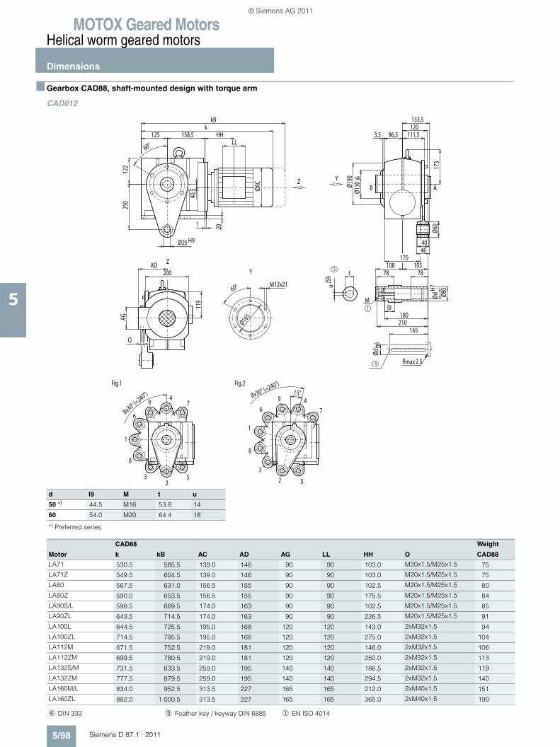
MOTOX Geared MotorsHelical worm geared motors
Dimensions
5/98 Siemens D 87.1 · 2011
5
■ Gearbox CAD88, shaft-mounted design with torque arm
CAD012,
d l9 M t u
50 *) 44.5 M16 53.8 14
60 54.0 M20 64.4 18
*) Preferred series
2
4
6
8
1
3 5
79
Fig.1
2
46
8
Fig.2
1
3
5
7
9
max2.5R
5
1
M
4
ABY
Y
Z
Z
HH
M12x2160°
Ø165AG
LL
8x30° (=240°) 8x30° (=240°)
15°
111,5120133,5
96,5
Ø60
173
250
40Ø25 H946
3,5
60°
Ø130
j6
170
Ødh6
t
uJS
9
ØdH7
Ø80
l9
78 78
180210
165
108 105
20
O
119
AD200
Ø190
1
122
ØAC
125 158,5k
40,5
kB
CAD88 Weight
Motor k kB AC AD AG LL HH O CAD88
LA71 530.5 585.5 139.0 146 90 90 103.0 M20x1.5/M25x1.5 75
LA71Z 549.5 604.5 139.0 146 90 90 103.0 M20x1.5/M25x1.5 75
LA80 567.5 631.0 156.5 155 90 90 102.5 M20x1.5/M25x1.5 80
LA80Z 590.0 653.5 156.5 155 90 90 175.5 M20x1.5/M25x1.5 84
LA90S/L 598.5 669.5 174.0 163 90 90 102.5 M20x1.5/M25x1.5 85
LA90ZL 643.5 714.5 174.0 163 90 90 226.5 M20x1.5/M25x1.5 91
LA100L 644.5 725.5 195.0 168 120 120 143.0 2xM32x1.5 94
LA100ZL 714.5 795.5 195.0 168 120 120 275.0 2xM32x1.5 104
LA112M 671.5 752.5 219.0 181 120 120 146.0 2xM32x1.5 106
LA112ZM 699.5 780.5 219.0 181 120 120 250.0 2xM32x1.5 113
LA132S/M 731.5 833.5 259.0 195 140 140 186.5 2xM32x1.5 119
LA132ZM 777.5 879.5 259.0 195 140 140 294.5 2xM32x1.5 140
LA160M/L 834.0 952.5 313.5 227 165 165 212.0 2xM40x1.5 151
LA160ZL 882.0 1 000.5 313.5 227 165 165 365.0 2xM40x1.5 190
➃ DIN 332 ➄ Feather key / keyway DIN 6885 ➀ EN ISO 4014
© Siemens AG 2011
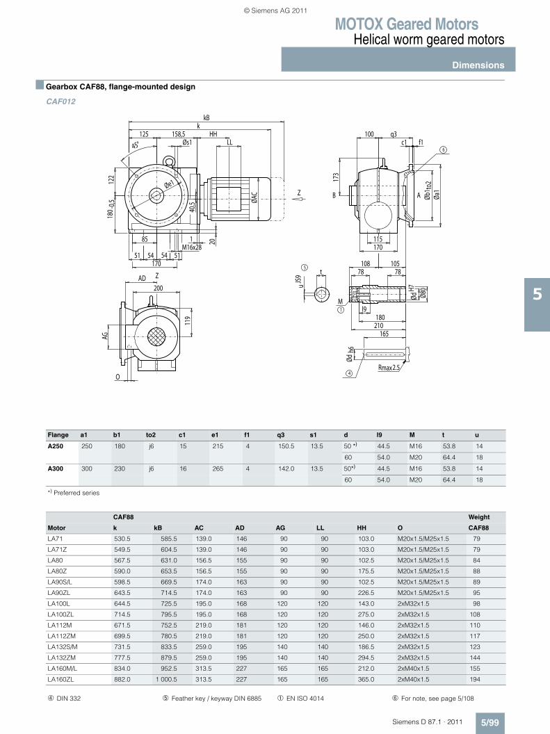
MOTOX Geared MotorsHelical worm geared motors
Dimensions
5/99Siemens D 87.1 · 2011
5
■ Gearbox CAF88, flange-mounted design
CAF012
Flange a1 b1 to2 c1 e1 f1 q3 s1 d l9 M t u
A250 250 180 j6 15 215 4 150.5 13.5 50 *) 44.5 M16 53.8 14
60 54.0 M20 64.4 18
A300 300 230 j6 16 265 4 142.0 13.5 50*) 44.5 M16 53.8 14
60 54.0 M20 64.4 18
*) Preferred series
Z
Z
max2.5R
5
1
M
4
AB
6
HH
AG
M16x28
ØdH7
Øb1 t
o2
173
115
100 q3
t
uJS
9
Ø80
Ødh6
l9
78 78
180210
165
108 105
170
20
O
119
AD200
Øa1
c1 f1
1
17051
85
5154 54
122
180 -
0,5 ØAC
45°125 158,5
Øs1
kkB
40,5
LL
Øe1
CAF88 Weight
Motor k kB AC AD AG LL HH O CAF88
LA71 530.5 585.5 139.0 146 90 90 103.0 M20x1.5/M25x1.5 79
LA71Z 549.5 604.5 139.0 146 90 90 103.0 M20x1.5/M25x1.5 79
LA80 567.5 631.0 156.5 155 90 90 102.5 M20x1.5/M25x1.5 84
LA80Z 590.0 653.5 156.5 155 90 90 175.5 M20x1.5/M25x1.5 88
LA90S/L 598.5 669.5 174.0 163 90 90 102.5 M20x1.5/M25x1.5 89
LA90ZL 643.5 714.5 174.0 163 90 90 226.5 M20x1.5/M25x1.5 95
LA100L 644.5 725.5 195.0 168 120 120 143.0 2xM32x1.5 98
LA100ZL 714.5 795.5 195.0 168 120 120 275.0 2xM32x1.5 108
LA112M 671.5 752.5 219.0 181 120 120 146.0 2xM32x1.5 110
LA112ZM 699.5 780.5 219.0 181 120 120 250.0 2xM32x1.5 117
LA132S/M 731.5 833.5 259.0 195 140 140 186.5 2xM32x1.5 123
LA132ZM 777.5 879.5 259.0 195 140 140 294.5 2xM32x1.5 144
LA160M/L 834.0 952.5 313.5 227 165 165 212.0 2xM40x1.5 155
LA160ZL 882.0 1 000.5 313.5 227 165 165 365.0 2xM40x1.5 194
➃ DIN 332 ➄ Feather key / keyway DIN 6885 ➀ EN ISO 4014 ➅ For note, see page 5/108
© Siemens AG 2011
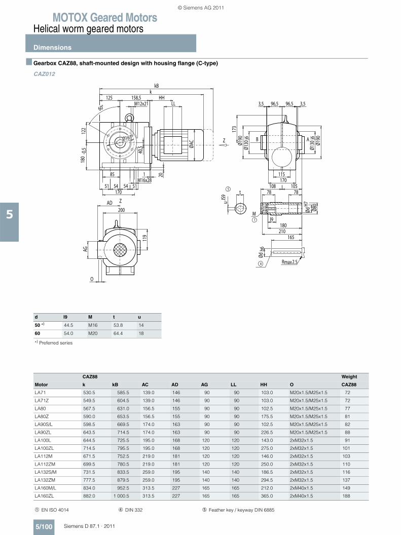
MOTOX Geared MotorsHelical worm geared motors
Dimensions
5/100 Siemens D 87.1 · 2011
5
■ Gearbox CAZ88, shaft-mounted design with housing flange (C-type)
CAZ012
d l9 M t u
50 *) 44.5 M16 53.8 14
60 54.0 M20 64.4 18
*) Preferred series
CAZ88 Weight
Motor k kB AC AD AG LL HH O CAZ88
LA71 530.5 585.5 139.0 146 90 90 103.0 M20x1.5/M25x1.5 72
LA71Z 549.5 604.5 139.0 146 90 90 103.0 M20x1.5/M25x1.5 72
LA80 567.5 631.0 156.5 155 90 90 102.5 M20x1.5/M25x1.5 77
LA80Z 590.0 653.5 156.5 155 90 90 175.5 M20x1.5/M25x1.5 81
LA90S/L 598.5 669.5 174.0 163 90 90 102.5 M20x1.5/M25x1.5 82
LA90ZL 643.5 714.5 174.0 163 90 90 226.5 M20x1.5/M25x1.5 88
LA100L 644.5 725.5 195.0 168 120 120 143.0 2xM32x1.5 91
LA100ZL 714.5 795.5 195.0 168 120 120 275.0 2xM32x1.5 101
LA112M 671.5 752.5 219.0 181 120 120 146.0 2xM32x1.5 103
LA112ZM 699.5 780.5 219.0 181 120 120 250.0 2xM32x1.5 110
LA132S/M 731.5 833.5 259.0 195 140 140 186.5 2xM32x1.5 116
LA132ZM 777.5 879.5 259.0 195 140 140 294.5 2xM32x1.5 137
LA160M/L 834.0 952.5 313.5 227 165 165 212.0 2xM40x1.5 149
LA160ZL 882.0 1 000.5 313.5 227 165 165 365.0 2xM40x1.5 188
➀ EN ISO 4014 ➃ DIN 332 ➄ Feather key / keyway DIN 6885
Z
Z
max2.5R
5
1
M
4
AB
HH
AG
LL
54 54M16x28
96,5 96,5
173
Ø165
85
51 51
115
170
3,53,560°
Ø130
j6
Ø130
j6
170
Ødh6
t
uJS
9
ØdH7
Ø80
l9
78 78
180210
165
108 105
20
O
119
AD200
Ø190
Ø190
1
122
180
M12x21
-0,5 ØA
C
125 158,5k
40,5
kB
© Siemens AG 2011
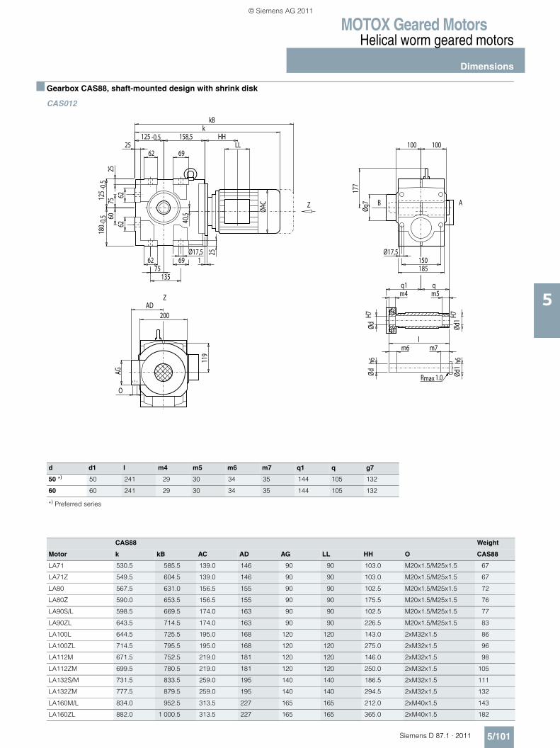
MOTOX Geared MotorsHelical worm geared motors
Dimensions
5/101Siemens D 87.1 · 2011
5
■ Gearbox CAS88, shaft-mounted design with shrink disk
CAS012
d d1 l m4 m5 m6 m7 q1 q g7
50 *) 50 241 29 30 34 35 144 105 132
60 60 241 29 30 34 35 144 105 132
*) Preferred series
CAS88 Weight
Motor k kB AC AD AG LL HH O CAS88
LA71 530.5 585.5 139.0 146 90 90 103.0 M20x1.5/M25x1.5 67
LA71Z 549.5 604.5 139.0 146 90 90 103.0 M20x1.5/M25x1.5 67
LA80 567.5 631.0 156.5 155 90 90 102.5 M20x1.5/M25x1.5 72
LA80Z 590.0 653.5 156.5 155 90 90 175.5 M20x1.5/M25x1.5 76
LA90S/L 598.5 669.5 174.0 163 90 90 102.5 M20x1.5/M25x1.5 77
LA90ZL 643.5 714.5 174.0 163 90 90 226.5 M20x1.5/M25x1.5 83
LA100L 644.5 725.5 195.0 168 120 120 143.0 2xM32x1.5 86
LA100ZL 714.5 795.5 195.0 168 120 120 275.0 2xM32x1.5 96
LA112M 671.5 752.5 219.0 181 120 120 146.0 2xM32x1.5 98
LA112ZM 699.5 780.5 219.0 181 120 120 250.0 2xM32x1.5 105
LA132S/M 731.5 833.5 259.0 195 140 140 186.5 2xM32x1.5 111
LA132ZM 777.5 879.5 259.0 195 140 140 294.5 2xM32x1.5 132
LA160M/L 834.0 952.5 313.5 227 165 165 212.0 2xM40x1.5 143
LA160ZL 882.0 1 000.5 313.5 227 165 165 365.0 2xM40x1.5 182
Z
Z
maxR 1.0
AB
HH
AG
LL
Øg7
177
Ød1
h6Ød
1H7
ØdH7
m4q1 q
m5
lm6 m7
Ødh6
75
25
40,5
119
25
1
135
O
200AD
Ø17,5
100 100
Ø17,5150185
7560
180 -
0,512
5-0
,5
62 69
25125 -0,5 158,5
kkB
ØAC
6962
6262
© Siemens AG 2011
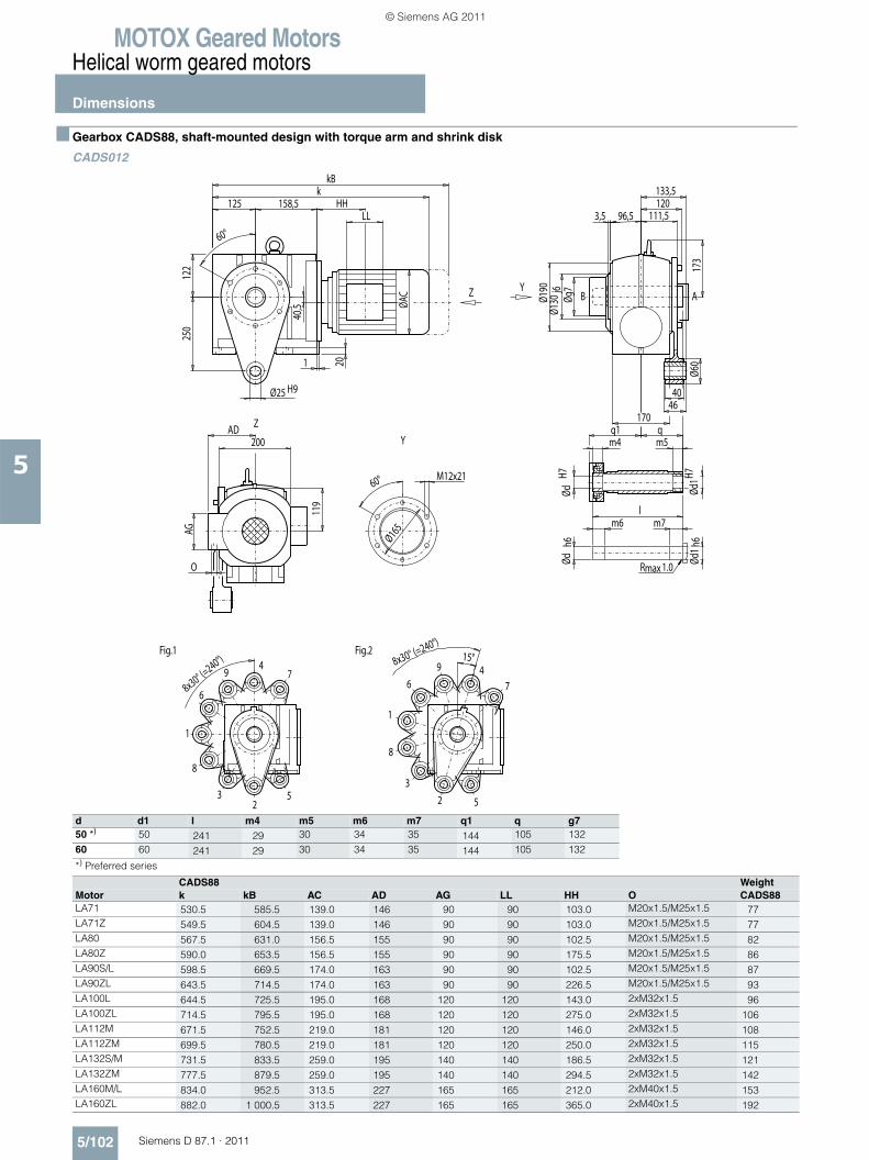
MOTOX Geared MotorsHelical worm geared motors
Dimensions
5/102 Siemens D 87.1 · 2011
5
■ Gearbox CADS88, shaft-mounted design with torque arm and shrink disk
CADS012
d d1 l m4 m5 m6 m7 q1 q g750 *) 50 241 29 30 34 35 144 105 13260 60 241 29 30 34 35 144 105 132
*) Preferred series
CADS88 WeightMotor k kB AC AD AG LL HH O CADS88LA71 530.5 585.5 139.0 146 90 90 103.0 M20x1.5/M25x1.5 77LA71Z 549.5 604.5 139.0 146 90 90 103.0 M20x1.5/M25x1.5 77LA80 567.5 631.0 156.5 155 90 90 102.5 M20x1.5/M25x1.5 82LA80Z 590.0 653.5 156.5 155 90 90 175.5 M20x1.5/M25x1.5 86LA90S/L 598.5 669.5 174.0 163 90 90 102.5 M20x1.5/M25x1.5 87LA90ZL 643.5 714.5 174.0 163 90 90 226.5 M20x1.5/M25x1.5 93LA100L 644.5 725.5 195.0 168 120 120 143.0 2xM32x1.5 96LA100ZL 714.5 795.5 195.0 168 120 120 275.0 2xM32x1.5 106LA112M 671.5 752.5 219.0 181 120 120 146.0 2xM32x1.5 108LA112ZM 699.5 780.5 219.0 181 120 120 250.0 2xM32x1.5 115LA132S/M 731.5 833.5 259.0 195 140 140 186.5 2xM32x1.5 121LA132ZM 777.5 879.5 259.0 195 140 140 294.5 2xM32x1.5 142LA160M/L 834.0 952.5 313.5 227 165 165 212.0 2xM40x1.5 153LA160ZL 882.0 1 000.5 313.5 227 165 165 365.0 2xM40x1.5 192
2
4
6
8
1
3 5
79
Fig.1
2
46
8
Fig.2
1
3
5
7
9
maxR 1.0
ABY
Y
Z
Z
HH
M12x2160°
Ø165AG
LL
8x30° (=240°) 8x30° (=240°)
15°
133,5120
111,596,5
173
Øg7
Ød1 h
6Ød
1H7
ØdH7
m4q1 q
m5
lm6 m7
Ødh6
Ø60
250
40Ø25 H946
3,5
60°
Ø130
j6
170
20
O
119
AD200
Ø190
1
122
ØAC
125 158,5k
40,5
kB
© Siemens AG 2011
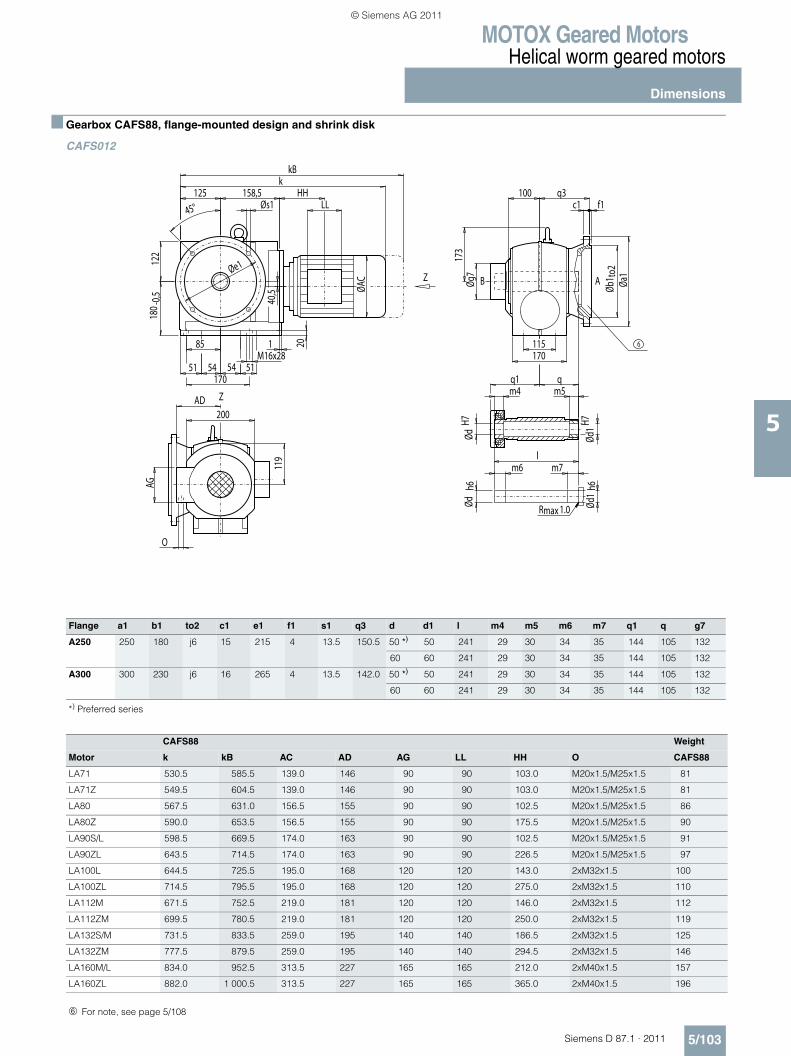
MOTOX Geared MotorsHelical worm geared motors
Dimensions
5/103Siemens D 87.1 · 2011
5
■ Gearbox CAFS88, flange-mounted design and shrink disk
CAFS012
Flange a1 b1 to2 c1 e1 f1 s1 q3 d d1 l m4 m5 m6 m7 q1 q g7
A250 250 180 j6 15 215 4 13.5 150.5 50 *) 50 241 29 30 34 35 144 105 132
60 60 241 29 30 34 35 144 105 132
A300 300 230 j6 16 265 4 13.5 142.0 50 *) 50 241 29 30 34 35 144 105 132
60 60 241 29 30 34 35 144 105 132
*) Preferred series
CAFS88 Weight
Motor k kB AC AD AG LL HH O CAFS88
LA71 530.5 585.5 139.0 146 90 90 103.0 M20x1.5/M25x1.5 81
LA71Z 549.5 604.5 139.0 146 90 90 103.0 M20x1.5/M25x1.5 81
LA80 567.5 631.0 156.5 155 90 90 102.5 M20x1.5/M25x1.5 86
LA80Z 590.0 653.5 156.5 155 90 90 175.5 M20x1.5/M25x1.5 90
LA90S/L 598.5 669.5 174.0 163 90 90 102.5 M20x1.5/M25x1.5 91
LA90ZL 643.5 714.5 174.0 163 90 90 226.5 M20x1.5/M25x1.5 97
LA100L 644.5 725.5 195.0 168 120 120 143.0 2xM32x1.5 100
LA100ZL 714.5 795.5 195.0 168 120 120 275.0 2xM32x1.5 110
LA112M 671.5 752.5 219.0 181 120 120 146.0 2xM32x1.5 112
LA112ZM 699.5 780.5 219.0 181 120 120 250.0 2xM32x1.5 119
LA132S/M 731.5 833.5 259.0 195 140 140 186.5 2xM32x1.5 125
LA132ZM 777.5 879.5 259.0 195 140 140 294.5 2xM32x1.5 146
LA160M/L 834.0 952.5 313.5 227 165 165 212.0 2xM40x1.5 157
LA160ZL 882.0 1 000.5 313.5 227 165 165 365.0 2xM40x1.5 196
Z
Z
maxR 1.0
AB
6
HH
AG
LL
173
Øg7
115
Ød1
h6Ød
1H7
ØdH7
m4q1 q
m5
lm6 m7
Ødh6
100 q3
170
20
O
119
AD200
Øb1 t
o2Øa
1
c1 f1
1
17051
85
54 54M16x28
51
122
180 -
0,5
ØAC
45°125 158,5
Øs1
kkB
40,5
Øe1
➅ For note, see page 5/108
© Siemens AG 2011
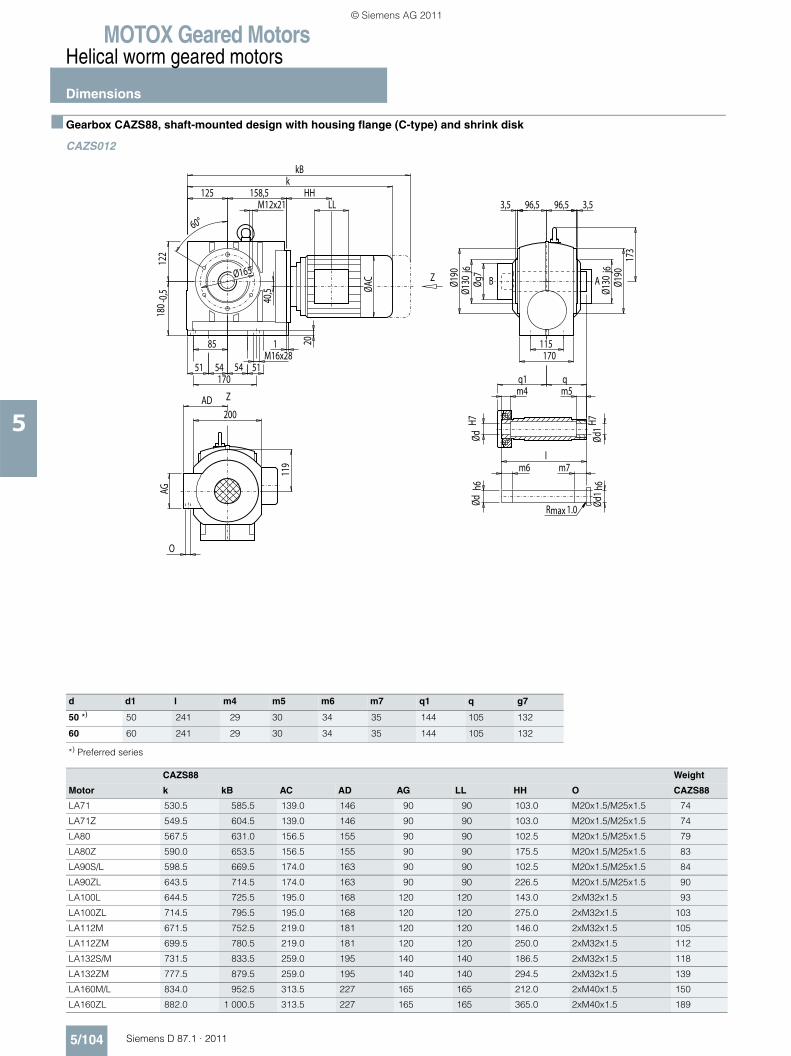
MOTOX Geared MotorsHelical worm geared motors
Dimensions
5/104 Siemens D 87.1 · 2011
5
■ Gearbox CAZS88, shaft-mounted design with housing flange (C-type) and shrink disk
CAZS012
d d1 l m4 m5 m6 m7 q1 q g7
50 *) 50 241 29 30 34 35 144 105 132
60 60 241 29 30 34 35 144 105 132
*) Preferred series
CAZS88 Weight
Motor k kB AC AD AG LL HH O CAZS88
LA71 530.5 585.5 139.0 146 90 90 103.0 M20x1.5/M25x1.5 74
LA71Z 549.5 604.5 139.0 146 90 90 103.0 M20x1.5/M25x1.5 74
LA80 567.5 631.0 156.5 155 90 90 102.5 M20x1.5/M25x1.5 79
LA80Z 590.0 653.5 156.5 155 90 90 175.5 M20x1.5/M25x1.5 83
LA90S/L 598.5 669.5 174.0 163 90 90 102.5 M20x1.5/M25x1.5 84
LA90ZL 643.5 714.5 174.0 163 90 90 226.5 M20x1.5/M25x1.5 90
LA100L 644.5 725.5 195.0 168 120 120 143.0 2xM32x1.5 93
LA100ZL 714.5 795.5 195.0 168 120 120 275.0 2xM32x1.5 103
LA112M 671.5 752.5 219.0 181 120 120 146.0 2xM32x1.5 105
LA112ZM 699.5 780.5 219.0 181 120 120 250.0 2xM32x1.5 112
LA132S/M 731.5 833.5 259.0 195 140 140 186.5 2xM32x1.5 118
LA132ZM 777.5 879.5 259.0 195 140 140 294.5 2xM32x1.5 139
LA160M/L 834.0 952.5 313.5 227 165 165 212.0 2xM40x1.5 150
LA160ZL 882.0 1 000.5 313.5 227 165 165 365.0 2xM40x1.5 189
Z
Z
maxR 1.0
AB
HH
AG
LL
54 54M16x28
96,5 96,5
Øg7
173
Ød1
H7Ød
1 h6
ØdH7
m4q1 q
m5
lm6 m7
Ødh6
Ø165
85
51 51
115
170
3,53,5
60°
Ø130
j6
Ø130
j6
170
20
O
119
AD200
Ø190
Ø190
1
122
180 -
0,5
ØAC
125 158,5M12x21
k
40,5
kB
© Siemens AG 2011
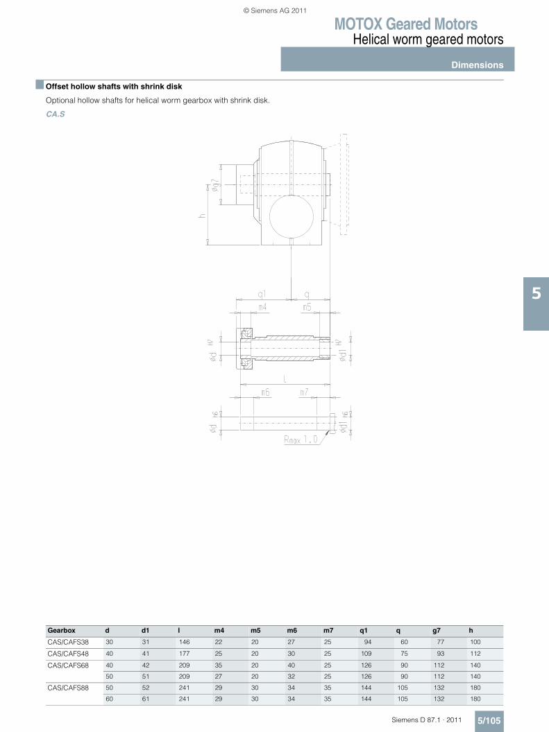
MOTOX Geared MotorsHelical worm geared motors
Dimensions
5/105Siemens D 87.1 · 2011
5
■ Offset hollow shafts with shrink disk
Optional hollow shafts for helical worm gearbox with shrink disk.
CA.S
Gearbox d d1 l m4 m5 m6 m7 q1 q g7 h
CAS/CAFS38 30 31 146 22 20 27 25 94 60 77 100
CAS/CAFS48 40 41 177 25 20 30 25 109 75 93 112
CAS/CAFS68 40 42 209 35 20 40 25 126 90 112 140
50 51 209 27 20 32 25 126 90 112 140
CAS/CAFS88 50 52 241 29 30 34 35 144 105 132 180
60 61 241 29 30 34 35 144 105 132 180
© Siemens AG 2011
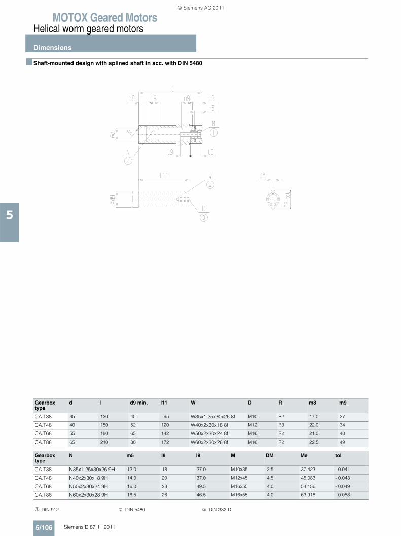
MOTOX Geared MotorsHelical worm geared motors
Dimensions
5/106 Siemens D 87.1 · 2011
5
■ Shaft-mounted design with splined shaft in acc. with DIN 5480
Gearbox type
d l d9 min. l11 W D R m8 m9
CA.T38 35 120 45 95 W35x1.25x30x26 8f M10 R2 17.0 27
CA.T48 40 150 52 120 W40x2x30x18 8f M12 R3 22.0 34
CA.T68 55 180 65 142 W50x2x30x24 8f M16 R2 21.0 40
CA.T88 65 210 80 172 W60x2x30x28 8f M16 R2 22.5 49
Gearbox type
N m5 l8 l9 M DM Me tol
CA.T38 N35x1.25x30x26 9H 12.0 18 27.0 M10x35 2.5 37.423 - 0.041
CA.T48 N40x2x30x18 9H 14.0 20 37.0 M12x45 4.5 45.083 - 0.043
CA.T68 N50x2x30x24 9H 16.0 23 49.5 M16x55 4.0 54.156 - 0.049
CA.T88 N60x2x30x28 9H 16.5 26 46.5 M16x55 4.0 63.918 - 0.053
➀ DIN 912 ➁ DIN 5480 ➂ DIN 332-D
© Siemens AG 2011
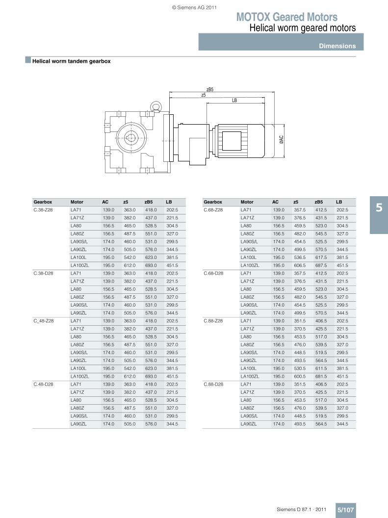
MOTOX Geared MotorsHelical worm geared motors
Dimensions
5/107Siemens D 87.1 · 2011
5
■ Helical worm tandem gearbox
LB
ØAC
z5zB5
Gearbox Motor AC z5 zB5 LB Gearbox Motor AC z5 zB5 LB
C.38-Z28 LA71 139.0 363.0 418.0 202.5 C.68-Z28 LA71 139.0 357.5 412.5 202.5
LA71Z 139.0 382.0 437.0 221.5 LA71Z 139.0 376.5 431.5 221.5
LA80 156.5 465.0 528.5 304.5 LA80 156.5 459.5 523.0 304.5
LA80Z 156.5 487.5 551.0 327.0 LA80Z 156.5 482.0 545.5 327.0
LA90S/L 174.0 460.0 531.0 299.5 LA90S/L 174.0 454.5 525.5 299.5
LA90ZL 174.0 505.0 576.0 344.5 LA90ZL 174.0 499.5 570.5 344.5
LA100L 195.0 542.0 623.0 381.5 LA100L 195.0 536.5 617.5 381.5
LA100ZL 195.0 612.0 693.0 451.5 LA100ZL 195.0 606.5 687.5 451.5
C.38-D28 LA71 139.0 363.0 418.0 202.5 C.68-D28 LA71 139.0 357.5 412.5 202.5
LA71Z 139.0 382.0 437.0 221.5 LA71Z 139.0 376.5 431.5 221.5
LA80 156.5 465.0 528.5 304.5 LA80 156.5 459.5 523.0 304.5
LA80Z 156.5 487.5 551.0 327.0 LA80Z 156.5 482.0 545.5 327.0
LA90S/L 174.0 460.0 531.0 299.5 LA90S/L 174.0 454.5 525.5 299.5
LA90ZL 174.0 505.0 576.0 344.5 LA90ZL 174.0 499.5 570.5 344.5
C_48-Z28 LA71 139.0 363.0 418.0 202.5 C.88-Z28 LA71 139.0 351.5 406.5 202.5
LA71Z 139.0 382.0 437.0 221.5 LA71Z 139.0 370.5 425.5 221.5
LA80 156.5 465.0 528.5 304.5 LA80 156.5 453.5 517.0 304.5
LA80Z 156.5 487.5 551.0 327.0 LA80Z 156.5 476.0 539.5 327.0
LA90S/L 174.0 460.0 531.0 299.5 LA90S/L 174.0 448.5 519.5 299.5
LA90ZL 174.0 505.0 576.0 344.5 LA90ZL 174.0 493.5 564.5 344.5
LA100L 195.0 542.0 623.0 381.5 LA100L 195.0 530.5 611.5 381.5
LA100ZL 195.0 612.0 693.0 451.5 LA100ZL 195.0 600.5 681.5 451.5
C.48-D28 LA71 139.0 363.0 418.0 202.5 C.88-D28 LA71 139.0 351.5 406.5 202.5
LA71Z 139.0 382.0 437.0 221.5 LA71Z 139.0 370.5 425.5 221.5
LA80 156.5 465.0 528.5 304.5 LA80 156.5 453.5 517.0 304.5
LA80Z 156.5 487.5 551.0 327.0 LA80Z 156.5 476.0 539.5 327.0
LA90S/L 174.0 460.0 531.0 299.5 LA90S/L 174.0 448.5 519.5 299.5
LA90ZL 174.0 505.0 576.0 344.5 LA90ZL 174.0 493.5 564.5 344.5
© Siemens AG 2011
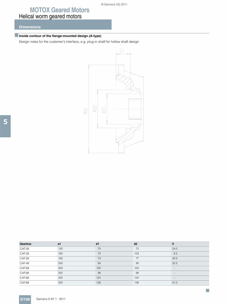
MOTOX Geared MotorsHelical worm geared motors
Dimensions
5/108 Siemens D 87.1 · 2011
5
■ Inside contour of the flange-mounted design (A-type)
Design notes for the customer's interface, e.g. plug-in shaft for hollow shaft design
Gearbox a1 d1 d2 l1
CAF.28 120 70 72 24.0
CAF.28 160 70 103 8.5
CAF.38 160 70 77 20.0
CAF.48 200 84 90 22.5
CAF.68 200 100 100 –
CAF.68 250 96 96 –
CAF.88 250 124 124 –
CAF.88 300 126 138 31.0
© Siemens AG 2011
Siemens D 87.1 · 2011
7Orientation
7/2 Overview
General technical data7/4 Permissible radial forces and
torques7/6 Maximum motor weight
Input unit K27/7 Selection and ordering data
Input unit K47/9 Selection and ordering data
Input units KQ / KQS7/11 Selection and ordering data
Input unit A7/13 Selection and ordering data
Input unit P7/15 Selection and ordering data
Special versions7/17 Input units with backstop
K2X, AX, PX7/18 Friction clutch7/18 Speed monitoring
Dimensions7/19 Dimension drawing overview7/20 Dimension drawings
Input units
© Siemens AG 2011
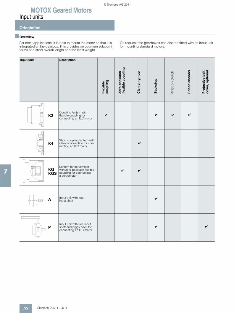
MOTOX Geared MotorsInput units
Orientation
7/2 Siemens D 87.1 · 2011
7
■ Overview
For most applications, it is best to mount the motor so that it is integrated on the gearbox. This provides an optimum solution in terms of a short overall length and the least weight.
On request, the gearboxes can also be fitted with an input unit for mounting standard motors.
Input unit Description
K2Coupling lantern with flexible coupling for connecting an IEC motor
✔ ✔ ✔ ✔
K4Short coupling lantern with clamp connection for con-necting an IEC motor
✔
KQKQS
Lantern for servomotor with zero-backlash flexible coupling for connecting a servomotor
✔ ✔
A Input unit with free input shaft
✔
PInput unit with free input shaft and piggy back for connecting an IEC motor
✔ ✔
Fle
xib
le
cou
plin
g
Zer
o-b
ackl
ash
fl
exib
le c
ou
plin
g
Cla
mp
ing
hu
b
Bac
ksto
p
Fri
ctio
n c
lutc
h
Sp
eed
en
cod
er
Pro
tect
ive
bel
t co
ver,
op
tio
nal
© Siemens AG 2011
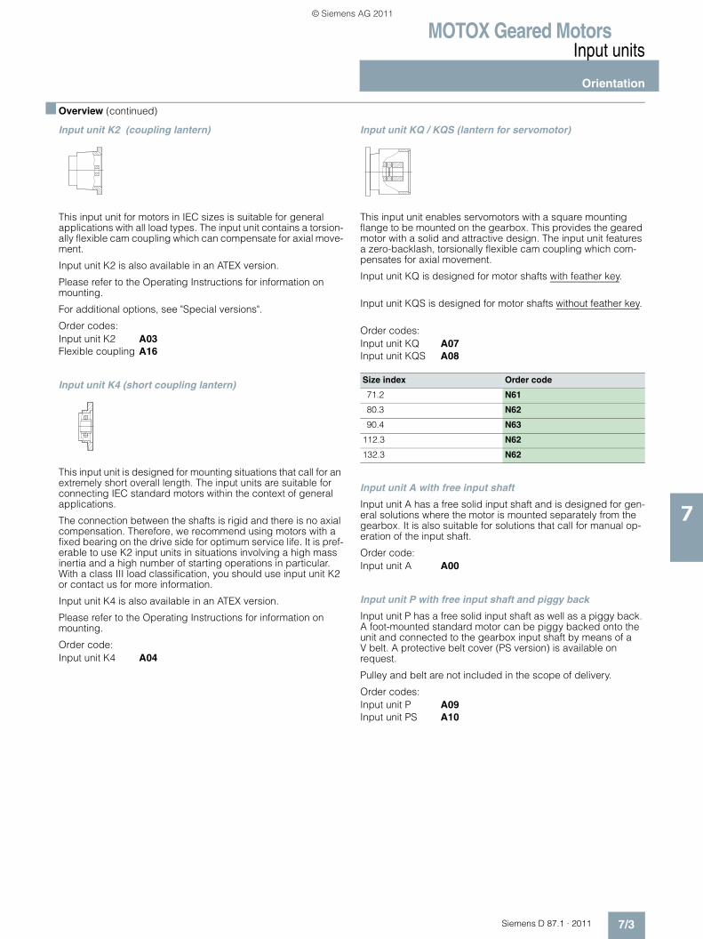
MOTOX Geared MotorsInput units
Orientation
7/3Siemens D 87.1 · 2011
7
■ Overview (continued)
Input unit K2 (coupling lantern)
This input unit for motors in IEC sizes is suitable for general applications with all load types. The input unit contains a torsion-ally flexible cam coupling which can compensate for axial move-ment.
Input unit K2 is also available in an ATEX version.
Please refer to the Operating Instructions for information on mounting.
For additional options, see "Special versions".
Order codes:Input unit K2 A03Flexible coupling A16
Input unit K4 (short coupling lantern)
This input unit is designed for mounting situations that call for an extremely short overall length. The input units are suitable for connecting IEC standard motors within the context of general applications.
The connection between the shafts is rigid and there is no axial compensation. Therefore, we recommend using motors with a fixed bearing on the drive side for optimum service life. It is pref-erable to use K2 input units in situations involving a high mass inertia and a high number of starting operations in particular. With a class III load classification, you should use input unit K2 or contact us for more information.
Input unit K4 is also available in an ATEX version.
Please refer to the Operating Instructions for information on mounting.
Order code:Input unit K4 A04
Input unit KQ / KQS (lantern for servomotor)
This input unit enables servomotors with a square mounting flange to be mounted on the gearbox. This provides the geared motor with a solid and attractive design. The input unit features a zero-backlash, torsionally flexible cam coupling which com-pensates for axial movement.
Input unit KQ is designed for motor shafts with feather key.
Input unit KQS is designed for motor shafts without feather key.
Order codes:Input unit KQ A07Input unit KQS A08
Input unit A with free input shaft
Input unit A has a free solid input shaft and is designed for gen-eral solutions where the motor is mounted separately from the gearbox. It is also suitable for solutions that call for manual op-eration of the input shaft.
Order code:Input unit A A00
Input unit P with free input shaft and piggy back
Input unit P has a free solid input shaft as well as a piggy back. A foot-mounted standard motor can be piggy backed onto the unit and connected to the gearbox input shaft by means of a V belt. A protective belt cover (PS version) is available on request.
Pulley and belt are not included in the scope of delivery.
Order codes:Input unit P A09Input unit PS A10
Size index Order code
71.2 N61
80.3 N62
90.4 N63
112.3 N62
132.3 N62
© Siemens AG 2011
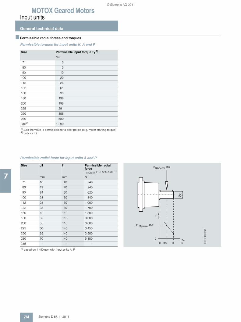
MOTOX Geared MotorsInput units
General technical data
7/4 Siemens D 87.1 · 2011
7
■ Permissible radial forces and torques
Permissible torques for input units K, A and P
Permissible radial force for input units A and P
Size Permissible input torque T1 1)
Nm
71 3
80 5
90 10
100 20
112 26
132 61
160 98
180 198
200 198
225 291
250 356
280 580
315 2) 1 290
1) 2.5x the value is permissible for a brief period (e.g. motor starting torque)2) only for K2
Size d1 l1 Permissible radial force FRAperm l1/2 at 0.5xl1 1)
mm mm N
71 16 40 240
80 19 40 240
90 24 50 620
100 28 60 840
112 28 60 1 000
132 38 80 1 700
160 42 110 1 800
180 55 110 3 000
200 55 110 3 000
225 60 140 3 450
250 65 140 3 900
280 70 140 5 150
315 – – –
1) based on 1 450 rpm with input units A, P
Ød1
l1/2
FRAperm
FRAperm
G_D
087_
EN
_001
27
l1/2
0
F
0 l1l1/2 x
© Siemens AG 2011
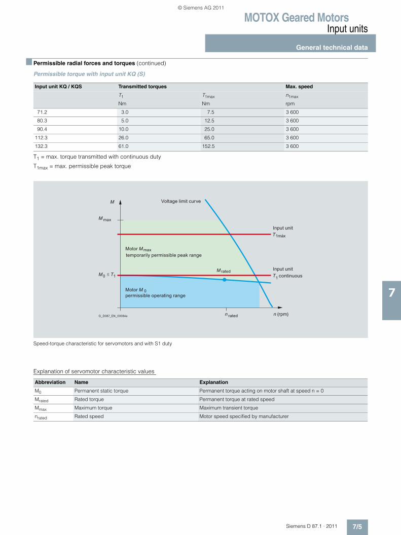
MOTOX Geared MotorsInput units
General technical data
7/5Siemens D 87.1 · 2011
7
■ Permissible radial forces and torques (continued)
Permissible torque with input unit KQ (S)
T1 = max. torque transmitted with continuous duty
T1max = max. permissible peak torque
Speed-torque characteristic for servomotors and with S1 duty
Explanation of servomotor characteristic values
Input unit KQ / KQS Transmitted torques Max. speed
T1 T1max n1max
Nm Nm rpm
71.2 3.0 7.5 3 600
80.3 5.0 12.5 3 600
90.4 10.0 25.0 3 600
112.3 26.0 65.0 3 600
132.3 61.0 152.5 3 600
n n
T1
T1máx
M rated
M
M
max
MMotor max
Motor M 0
G_D087_EN_00084a
M0 T1
Voltage limit curve
Input unit
Input unitcontinuous
temporarily permissible peak range
permissible operating range
(rpm)rated
Abbreviation Name Explanation
M0 Permanent static torque Permanent torque acting on motor shaft at speed n = 0
Mrated Rated torque Permanent torque at rated speed
Mmax Maximum torque Maximum transient torque
nrated Rated speed Motor speed specified by manufacturer
© Siemens AG 2011
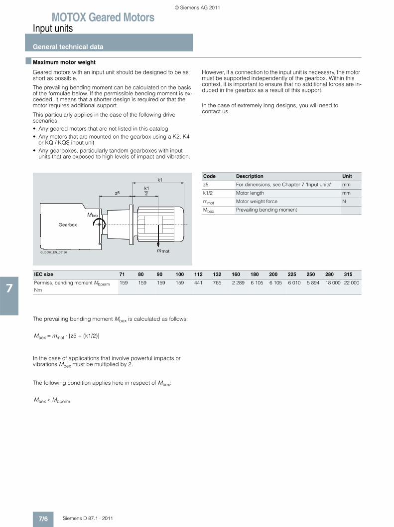
MOTOX Geared MotorsInput units
General technical data
7/6 Siemens D 87.1 · 2011
7
■ Maximum motor weight
Geared motors with an input unit should be designed to be as short as possible.
The prevailing bending moment can be calculated on the basis of the formulae below. If the permissible bending moment is ex-ceeded, it means that a shorter design is required or that the motor requires additional support.
This particularly applies in the case of the following drive scenarios:• Any geared motors that are not listed in this catalog• Any motors that are mounted on the gearbox using a K2, K4
or KQ / KQS input unit• Any gearboxes, particularly tandem gearboxes with input
units that are exposed to high levels of impact and vibration.
However, if a connection to the input unit is necessary, the motor must be supported independently of the gearbox. Within this context, it is important to ensure that no additional forces are in-duced in the gearbox as a result of this support.
In the case of extremely long designs, you will need to contact us.
The prevailing bending moment Mbex is calculated as follows:
In the case of applications that involve powerful impacts or vibrations Mbex must be multiplied by 2.
The following condition applies here in respect of Mbex:
Gearbox
G_D087_EN_00126
k1z5
k1
2
mot
bexM
m
Code Description Unit
z5 For dimensions, see Chapter 7 "Input units" mm
k1/2 Motor length mm
mmot Motor weight force N
Mbex Prevailing bending moment
IEC size 71 80 90 100 112 132 160 180 200 225 250 280 315
Permiss. bending moment Mbperm Nm
159 159 159 159 441 765 2 289 6 105 6 105 6 010 5 894 18 000 22 000
Mbex = mmot · {z5 + (k1/2)}
Mbex < Mbperm
© Siemens AG 2011
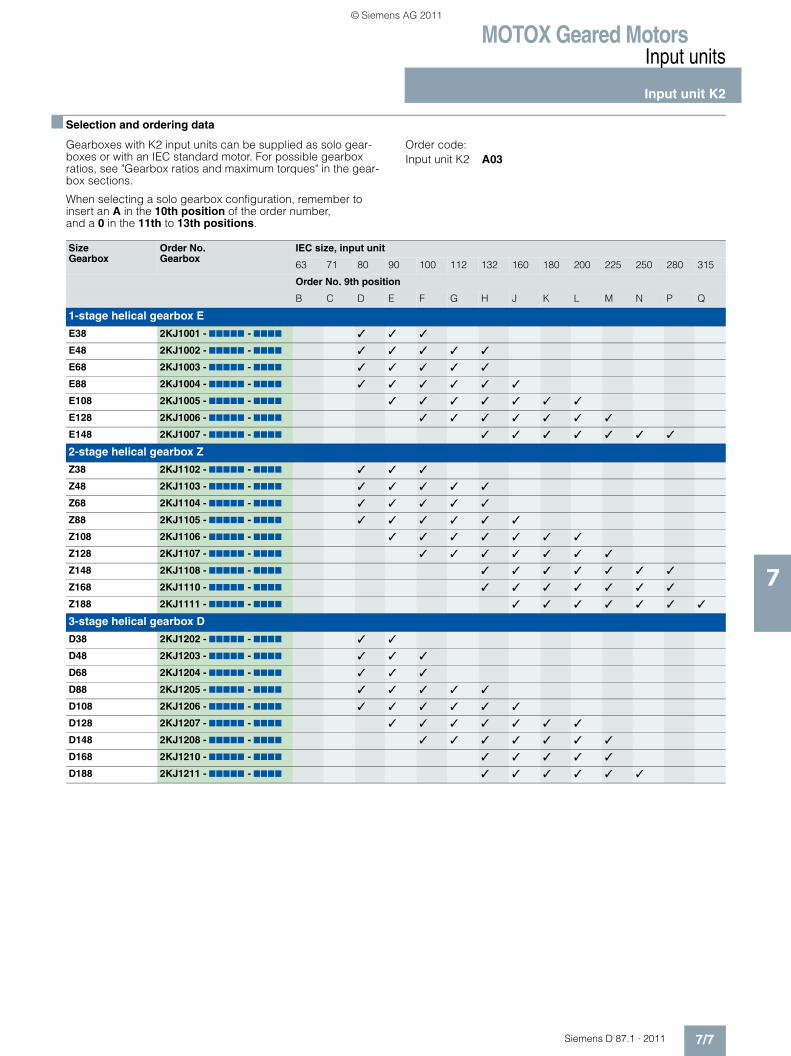
MOTOX Geared MotorsInput units
Input unit K2
7/7Siemens D 87.1 · 2011
7
■ Selection and ordering data
Gearboxes with K2 input units can be supplied as solo gear-boxes or with an IEC standard motor. For possible gearbox ratios, see "Gearbox ratios and maximum torques" in the gear-box sections.
When selecting a solo gearbox configuration, remember to insert an A in the 10th position of the order number, and a 0 in the 11th to 13th positions.
Order code:Input unit K2 A03
Size Gearbox
Order No. Gearbox
IEC size, input unit
63 71 80 90 100 112 132 160 180 200 225 250 280 315
Order No. 9th position
B C D E F G H J K L M N P Q
1-stage helical gearbox E
E38 2KJ1001 - 77777 - 7777 � � �
E48 2KJ1002 - 77777 - 7777 � � � � �
E68 2KJ1003 - 77777 - 7777 � � � � �
E88 2KJ1004 - 77777 - 7777 � � � � � �
E108 2KJ1005 - 77777 - 7777 � � � � � � �
E128 2KJ1006 - 77777 - 7777 � � � � � � �
E148 2KJ1007 - 77777 - 7777 � � � � � � �
2-stage helical gearbox Z
Z38 2KJ1102 - 77777 - 7777 � � �
Z48 2KJ1103 - 77777 - 7777 � � � � �
Z68 2KJ1104 - 77777 - 7777 � � � � �
Z88 2KJ1105 - 77777 - 7777 � � � � � �
Z108 2KJ1106 - 77777 - 7777 � � � � � � �
Z128 2KJ1107 - 77777 - 7777 � � � � � � �
Z148 2KJ1108 - 77777 - 7777 � � � � � � �
Z168 2KJ1110 - 77777 - 7777 � � � � � � �
Z188 2KJ1111 - 77777 - 7777 � � � � � � �
3-stage helical gearbox D
D38 2KJ1202 - 77777 - 7777 � �
D48 2KJ1203 - 77777 - 7777 � � �
D68 2KJ1204 - 77777 - 7777 � � �
D88 2KJ1205 - 77777 - 7777 � � � � �
D108 2KJ1206 - 77777 - 7777 � � � � � �
D128 2KJ1207 - 77777 - 7777 � � � � � � �
D148 2KJ1208 - 77777 - 7777 � � � � � � �
D168 2KJ1210 - 77777 - 7777 � � � � �
D188 2KJ1211 - 77777 - 7777 � � � � � �
© Siemens AG 2011

MOTOX Geared MotorsInput units
Input unit K2
7/8 Siemens D 87.1 · 2011
7
■ Selection and ordering data (continued)
Size Gearbox
Order No. Gearbox
IEC size, input unit
63 71 80 90 100 112 132 160 180 200 225 250 280 315
Order No. 9th position
B C D E F G H J K L M N P Q
2-stage parallel-shaft gearbox FZ
FZ38B 2KJ1301 - 77777 - 7777 � � �
FZ48B 2KJ1302 - 77777 - 7777 � � �
FZ68B 2KJ1303 - 77777 - 7777 � � � � �
FZ88B 2KJ1304 - 77777 - 7777 � � � � �
FZ108B 2KJ1305 - 77777 - 7777 � � � � � �
FZ128B 2KJ1306 - 77777 - 7777 � � � � � � �
FZ148B 2KJ1307 - 77777 - 7777 � � � � � � �
FZ168B 2KJ1308 - 77777 - 7777 � � � � � � �
FZ188B 2KJ1310 - 77777 - 7777 � � � � � � � �
FZ208 2KJ1311 - 77777 - 7777 � � � � � � �
3-stage parallel-shaft gearbox FD
FD38B 2KJ1401 - 77777 - 7777 � � �
FD48B 2KJ1402 - 77777 - 7777 � � �
FD68B 2KJ1403 - 77777 - 7777 � � � � �
FD88B 2KJ1404 - 77777 - 7777 � � � � �
FD108B 2KJ1405 - 77777 - 7777 � � � � � �
FD128B 2KJ1406 - 77777 - 7777 � � � � � � �
FD148B 2KJ1407 - 77777 - 7777 � � � � � � �
FD168B 2KJ1408 - 77777 - 7777 � � � � � � �
FD188B 2KJ1410 - 77777 - 7777 � � � � � � �
FD208 2KJ1411 - 77777 - 7777 � � � � � � � �
Bevel helical gearbox B
B38 2KJ1501 - 77777 - 7777 � � �
Bevel helical gearbox K
K38 2KJ1502 - 77777 - 7777 � � �
K48 2KJ1503 - 77777 - 7777 � � �
K68 2KJ1504 - 77777 - 7777 � � � � �
K88 2KJ1505 - 77777 - 7777 � � � � �
K108 2KJ1506 - 77777 - 7777 � � � � � �
K128 2KJ1507 - 77777 - 7777 � � � � � � �
K148 2KJ1508 - 77777 - 7777 � � � � � � �
K168 2KJ1510 - 77777 - 7777 � � � � � � �
K188 2KJ1511 - 77777 - 7777 � � � � � � � �
Helical worm gearbox C
C38 2KJ1601 - 77777 - 7777 � � �
C48 2KJ1602 - 77777 - 7777 � � �
C68 2KJ1603 - 77777 - 7777 � � � � �
C88 2KJ1604 - 77777 - 7777 � � � � �
© Siemens AG 2011
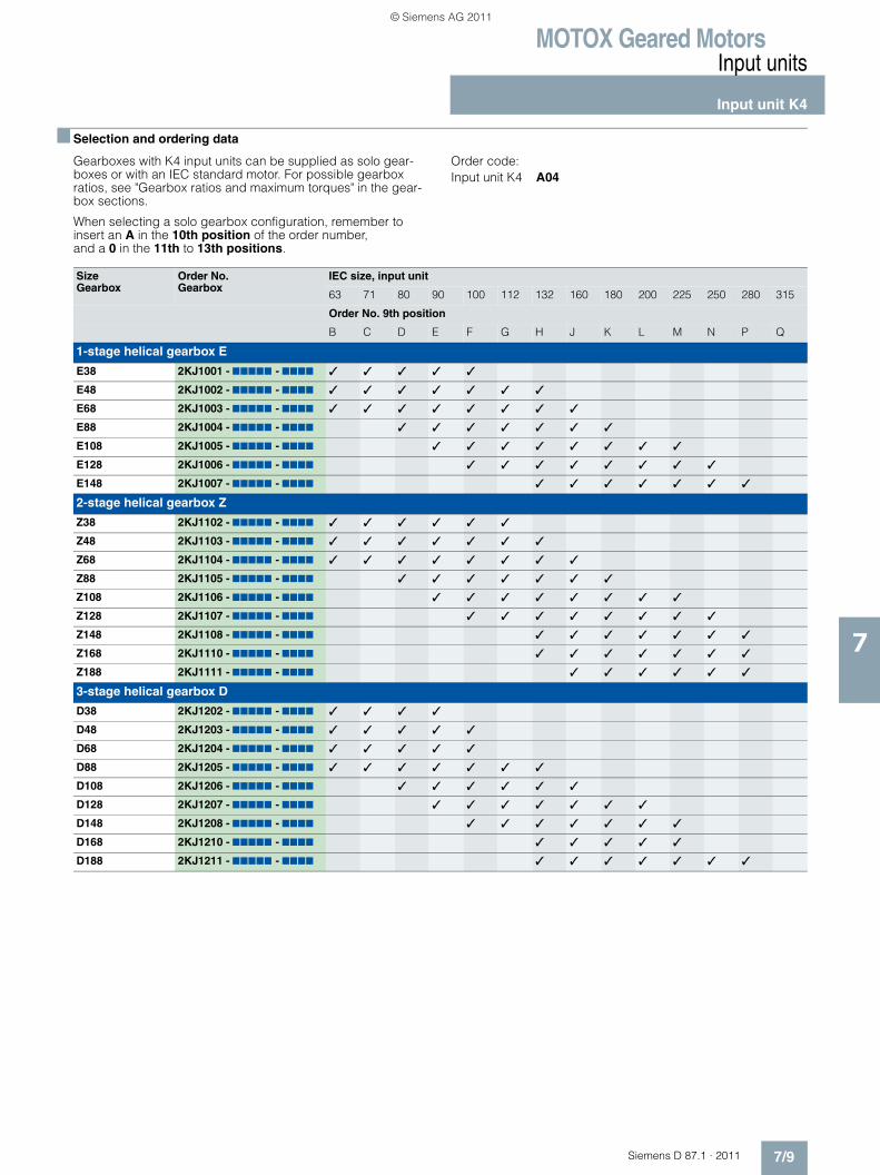
MOTOX Geared MotorsInput units
Input unit K4
7/9Siemens D 87.1 · 2011
7
■ Selection and ordering data
Gearboxes with K4 input units can be supplied as solo gear-boxes or with an IEC standard motor. For possible gearbox ratios, see "Gearbox ratios and maximum torques" in the gear-box sections.
When selecting a solo gearbox configuration, remember to insert an A in the 10th position of the order number, and a 0 in the 11th to 13th positions.
Order code: Input unit K4 A04
Size Gearbox
Order No. Gearbox
IEC size, input unit
63 71 80 90 100 112 132 160 180 200 225 250 280 315
Order No. 9th position
B C D E F G H J K L M N P Q
1-stage helical gearbox E
E38 2KJ1001 - 77777 - 7777 � � � � �
E48 2KJ1002 - 77777 - 7777 � � � � � � �
E68 2KJ1003 - 77777 - 7777 � � � � � � � �
E88 2KJ1004 - 77777 - 7777 � � � � � � �
E108 2KJ1005 - 77777 - 7777 � � � � � � � �
E128 2KJ1006 - 77777 - 7777 � � � � � � � �
E148 2KJ1007 - 77777 - 7777 � � � � � � �
2-stage helical gearbox Z
Z38 2KJ1102 - 77777 - 7777 � � � � � �
Z48 2KJ1103 - 77777 - 7777 � � � � � � �
Z68 2KJ1104 - 77777 - 7777 � � � � � � � �
Z88 2KJ1105 - 77777 - 7777 � � � � � � �
Z108 2KJ1106 - 77777 - 7777 � � � � � � � �
Z128 2KJ1107 - 77777 - 7777 � � � � � � � �
Z148 2KJ1108 - 77777 - 7777 � � � � � � �
Z168 2KJ1110 - 77777 - 7777 � � � � � � �
Z188 2KJ1111 - 77777 - 7777 � � � � � �
3-stage helical gearbox D
D38 2KJ1202 - 77777 - 7777 � � � �
D48 2KJ1203 - 77777 - 7777 � � � � �
D68 2KJ1204 - 77777 - 7777 � � � � �
D88 2KJ1205 - 77777 - 7777 � � � � � � �
D108 2KJ1206 - 77777 - 7777 � � � � � �
D128 2KJ1207 - 77777 - 7777 � � � � � � �
D148 2KJ1208 - 77777 - 7777 � � � � � � �
D168 2KJ1210 - 77777 - 7777 � � � � �
D188 2KJ1211 - 77777 - 7777 � � � � � � �
© Siemens AG 2011

MOTOX Geared MotorsInput units
Input unit K4
7/10 Siemens D 87.1 · 2011
7
■ Selection and ordering data (continued)
Size Gearbox
Order No. Gearbox
IEC size, input unit
63 71 80 90 100 112 132 160 180 200 225 250 280 315
Order No. 9th position
B C D E F G H J K L M N P Q
2-stage parallel-shaft gearbox FZ
FZ38B 2KJ1301 - 77777 - 7777 � � � � �
FZ48B 2KJ1302 - 77777 - 7777 � � � � � �
FZ68B 2KJ1303 - 77777 - 7777 � � � � � � �
FZ88B 2KJ1304 - 77777 - 7777 � � � � � � � �
FZ108B 2KJ1305 - 77777 - 7777 � � � � � � �
FZ128B 2KJ1306 - 77777 - 7777 � � � � � � � �
FZ148B 2KJ1307 - 77777 - 7777 � � � � � � � �
FZ168B 2KJ1308 - 77777 - 7777 � � � � � � �
FZ188B 2KJ1310 - 77777 - 7777 � � � � � � �
FZ208 2KJ1311 - 77777 - 7777 � � � � � �
3-stage parallel-shaft gearbox FD
FD38B 2KJ1401 - 77777 - 7777 � � � � �
FD48B 2KJ1402 - 77777 - 7777 � � � � � �
FD68B 2KJ1403 - 77777 - 7777 � � � � � � �
FD88B 2KJ1404 - 77777 - 7777 � � � � � � � �
FD108B 2KJ1405 - 77777 - 7777 � � � � � � �
FD128B 2KJ1406 - 77777 - 7777 � � � � � � � �
FD148B 2KJ1407 - 77777 - 7777 � � � � � � � �
FD168B 2KJ1408 - 77777 - 7777 � � � � � � �
FD188B 2KJ1410 - 77777 - 7777 � � � � � � �
FD208 2KJ1411 - 77777 - 7777 � � � � � � �
Bevel helical gearbox B
B38 2KJ1501 - 77777 - 7777 � � � � �
Bevel helical gearbox K
K38 2KJ1502 - 77777 - 7777 � � � � � �
K48 2KJ1503 - 77777 - 7777 � � � � � �
K68 2KJ1504 - 77777 - 7777 � � � � � � �
K88 2KJ1505 - 77777 - 7777 � � � � � � � �
K108 2KJ1506 - 77777 - 7777 � � � � � � �
K128 2KJ1507 - 77777 - 7777 � � � � � � � �
K148 2KJ1508 - 77777 - 7777 � � � � � � � �
K168 2KJ1510 - 77777 - 7777 � � � � � � �
K188 2KJ1511 - 77777 - 7777 � � � � � � �
Helical worm gearbox C
C38 2KJ1601 - 77777 - 7777 � � � � � �
C48 2KJ1602 - 77777 - 7777 � � � � � �
C68 2KJ1603 - 77777 - 7777 � � � � � � �
C88 2KJ1604 - 77777 - 7777 � � � � � � � �
© Siemens AG 2011
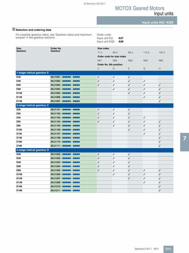
MOTOX Geared MotorsInput units
Input units KQ / KQS
7/11Siemens D 87.1 · 2011
7
■ Selection and ordering data
For possible gearbox ratios, see "Gearbox ratios and maximum torques" in the gearbox sections.
Order code:Input unit KQ A07Input unit KQS A08
Size Gearbox
Order No. Gearbox
Size index
71.2 80.3 90.4 112.3 132.3
Order code for size index
N61 N62 N63 N62 N62
Order No. 9th position
C D E G H
1-stage helical gearbox E
E38 2KJ1001 - 77777 - 7777 � � �
E48 2KJ1002 - 77777 - 7777 � � � �
E68 2KJ1003 - 77777 - 7777 � � � � �
E88 2KJ1004 - 77777 - 7777 � � � �
E108 2KJ1005 - 77777 - 7777 � � �
E128 2KJ1006 - 77777 - 7777 � �
E148 2KJ1007 - 77777 - 7777 �
2-stage helical gearbox Z
Z28 2KJ1101 - 77777 - 7777 � � �
Z38 2KJ1102 - 77777 - 7777 � � �
Z48 2KJ1103 - 77777 - 7777 � � � �
Z68 2KJ1104 - 77777 - 7777 � � � � �
Z88 2KJ1105 - 77777 - 7777 � � � �
Z108 2KJ1106 - 77777 - 7777 � � �
Z128 2KJ1107 - 77777 - 7777 � �
Z148 2KJ1108 - 77777 - 7777 �
Z168 2KJ1110 - 77777 - 7777 �
Z188 2KJ1111 - 77777 - 7777 �
3-stage helical gearbox D
D28 2KJ1202 - 77777 - 7777 � � �
D38 2KJ1202 - 77777 - 7777 � � �
D48 2KJ1203 - 77777 - 7777 � � �
D68 2KJ1204 - 77777 - 7777 � � �
D88 2KJ1205 - 77777 - 7777 � � � � �
D108 2KJ1206 - 77777 - 7777 � � � �
D128 2KJ1207 - 77777 - 7777 � � �
D148 2KJ1208 - 77777 - 7777 � �
D168 2KJ1210 - 77777 - 7777 �
D188 2KJ1211 - 77777 - 7777 �
© Siemens AG 2011
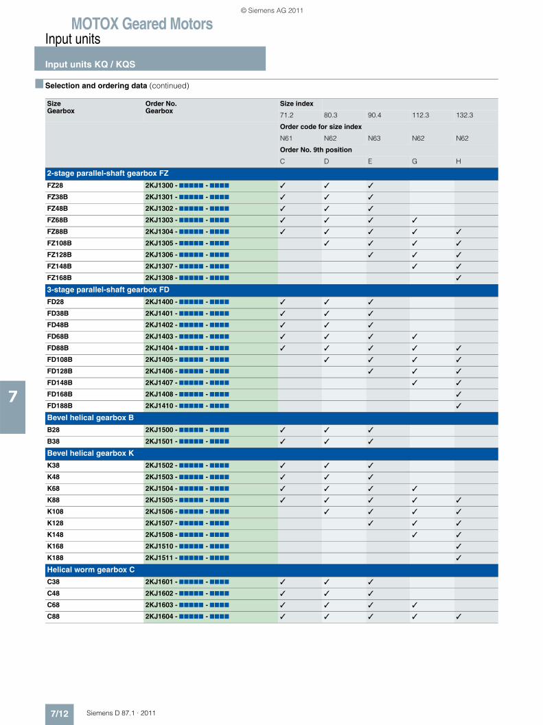
MOTOX Geared MotorsInput units
Input units KQ / KQS
7/12 Siemens D 87.1 · 2011
7
■ Selection and ordering data (continued)
Size Gearbox
Order No. Gearbox
Size index
71.2 80.3 90.4 112.3 132.3
Order code for size index
N61 N62 N63 N62 N62
Order No. 9th position
C D E G H
2-stage parallel-shaft gearbox FZ
FZ28 2KJ1300 - 77777 - 7777 � � �
FZ38B 2KJ1301 - 77777 - 7777 � � �
FZ48B 2KJ1302 - 77777 - 7777 � � �
FZ68B 2KJ1303 - 77777 - 7777 � � � �
FZ88B 2KJ1304 - 77777 - 7777 � � � � �
FZ108B 2KJ1305 - 77777 - 7777 � � � �
FZ128B 2KJ1306 - 77777 - 7777 � � �
FZ148B 2KJ1307 - 77777 - 7777 � �
FZ168B 2KJ1308 - 77777 - 7777 �
3-stage parallel-shaft gearbox FD
FD28 2KJ1400 - 77777 - 7777 � � �
FD38B 2KJ1401 - 77777 - 7777 � � �
FD48B 2KJ1402 - 77777 - 7777 � � �
FD68B 2KJ1403 - 77777 - 7777 � � � �
FD88B 2KJ1404 - 77777 - 7777 � � � � �
FD108B 2KJ1405 - 77777 - 7777 � � � �
FD128B 2KJ1406 - 77777 - 7777 � � �
FD148B 2KJ1407 - 77777 - 7777 � �
FD168B 2KJ1408 - 77777 - 7777 �
FD188B 2KJ1410 - 77777 - 7777 �
Bevel helical gearbox B
B28 2KJ1500 - 77777 - 7777 � � �
B38 2KJ1501 - 77777 - 7777 � � �
Bevel helical gearbox K
K38 2KJ1502 - 77777 - 7777 � � �
K48 2KJ1503 - 77777 - 7777 � � �
K68 2KJ1504 - 77777 - 7777 � � � �
K88 2KJ1505 - 77777 - 7777 � � � � �
K108 2KJ1506 - 77777 - 7777 � � � �
K128 2KJ1507 - 77777 - 7777 � � �
K148 2KJ1508 - 77777 - 7777 � �
K168 2KJ1510 - 77777 - 7777 �
K188 2KJ1511 - 77777 - 7777 �
Helical worm gearbox C
C38 2KJ1601 - 77777 - 7777 � � �
C48 2KJ1602 - 77777 - 7777 � � �
C68 2KJ1603 - 77777 - 7777 � � � �
C88 2KJ1604 - 77777 - 7777 � � � � �
© Siemens AG 2011

MOTOX Geared MotorsInput units
Input unit A
7/13Siemens D 87.1 · 2011
7
■ Selection and ordering data
For possible gearbox ratios, see "Gearbox ratios and maximum torques" in the gearbox sections.
Order code:Input unit A A00
Size Gearbox
Order No. Gearbox
Size, input unit
63 71 80 90 100 112 132 160 180 200 225 250 280 315
Order No. 9th position
B C D E F G H J K L M N P Q
1-stage helical gearbox E
E38 2KJ1001 - 77777 - 7777 � � � �
E48 2KJ1002 - 77777 - 7777 � � � � �
E68 2KJ1003 - 77777 - 7777 � � � � � �
E88 2KJ1004 - 77777 - 7777 � � � � � �
E108 2KJ1005 - 77777 - 7777 � � � � � �
E128 2KJ1006 - 77777 - 7777 � � � � � �
E148 2KJ1007 - 77777 - 7777 � � � � � �
2-stage helical gearbox Z
Z38 2KJ1102 - 77777 - 7777 � � � �
Z48 2KJ1103 - 77777 - 7777 � � � � �
Z68 2KJ1104 - 77777 - 7777 � � � � � �
Z88 2KJ1105 - 77777 - 7777 � � � � � �
Z108 2KJ1106 - 77777 - 7777 � � � � � �
Z128 2KJ1107 - 77777 - 7777 � � � � � �
Z148 2KJ1108 - 77777 - 7777 � � � � � �
Z168 2KJ1110 - 77777 - 7777 � � � � � �
Z188 2KJ1111 - 77777 - 7777 � � � � �
3-stage helical gearbox D
D38 2KJ1202 - 77777 - 7777 � � �
D48 2KJ1203 - 77777 - 7777 � � � �
D68 2KJ1204 - 77777 - 7777 � � � �
D88 2KJ1205 - 77777 - 7777 � � � � � �
D108 2KJ1206 - 77777 - 7777 � � � � � �
D128 2KJ1207 - 77777 - 7777 � � � � � �
D148 2KJ1208 - 77777 - 7777 � � � � � �
D168 2KJ1210 - 77777 - 7777 � � � �
D188 2KJ1211 - 77777 - 7777 � � � � � �
© Siemens AG 2011
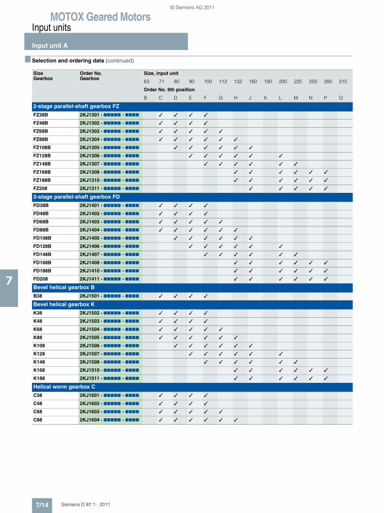
MOTOX Geared MotorsInput units
Input unit A
7/14 Siemens D 87.1 · 2011
7
■ Selection and ordering data (continued)
Size Gearbox
Order No. Gearbox
Size, input unit
63 71 80 90 100 112 132 160 180 200 225 250 280 315
Order No. 9th position
B C D E F G H J K L M N P Q
2-stage parallel-shaft gearbox FZ
FZ38B 2KJ1301 - 77777 - 7777 � � � �
FZ48B 2KJ1302 - 77777 - 7777 � � � �
FZ68B 2KJ1303 - 77777 - 7777 � � � � �
FZ88B 2KJ1304 - 77777 - 7777 � � � � � �
FZ108B 2KJ1305 - 77777 - 7777 � � � � � �
FZ128B 2KJ1306 - 77777 - 7777 � � � � � �
FZ148B 2KJ1307 - 77777 - 7777 � � � � � �
FZ168B 2KJ1308 - 77777 - 7777 � � � � � �
FZ188B 2KJ1310 - 77777 - 7777 � � � � � �
FZ208 2KJ1311 - 77777 - 7777 � � � � �
3-stage parallel-shaft gearbox FD
FD38B 2KJ1401 - 77777 - 7777 � � � �
FD48B 2KJ1402 - 77777 - 7777 � � � �
FD68B 2KJ1403 - 77777 - 7777 � � � � �
FD88B 2KJ1404 - 77777 - 7777 � � � � � �
FD108B 2KJ1405 - 77777 - 7777 � � � � � �
FD128B 2KJ1406 - 77777 - 7777 � � � � � �
FD148B 2KJ1407 - 77777 - 7777 � � � � � �
FD168B 2KJ1408 - 77777 - 7777 � � � � � �
FD188B 2KJ1410 - 77777 - 7777 � � � � � �
FD208 2KJ1411 - 77777 - 7777 � � � � � �
Bevel helical gearbox B
B38 2KJ1501 - 77777 - 7777 � � � �
Bevel helical gearbox K
K38 2KJ1502 - 77777 - 7777 � � � �
K48 2KJ1503 - 77777 - 7777 � � � �
K68 2KJ1504 - 77777 - 7777 � � � � �
K88 2KJ1505 - 77777 - 7777 � � � � � �
K108 2KJ1506 - 77777 - 7777 � � � � � �
K128 2KJ1507 - 77777 - 7777 � � � � � �
K148 2KJ1508 - 77777 - 7777 � � � � � �
K168 2KJ1510 - 77777 - 7777 � � � � � �
K188 2KJ1511 - 77777 - 7777 � � � � � �
Helical worm gearbox C
C38 2KJ1601 - 77777 - 7777 � � � �
C48 2KJ1602 - 77777 - 7777 � � � �
C68 2KJ1603 - 77777 - 7777 � � � � �
C88 2KJ1604 - 77777 - 7777 � � � � � �
© Siemens AG 2011
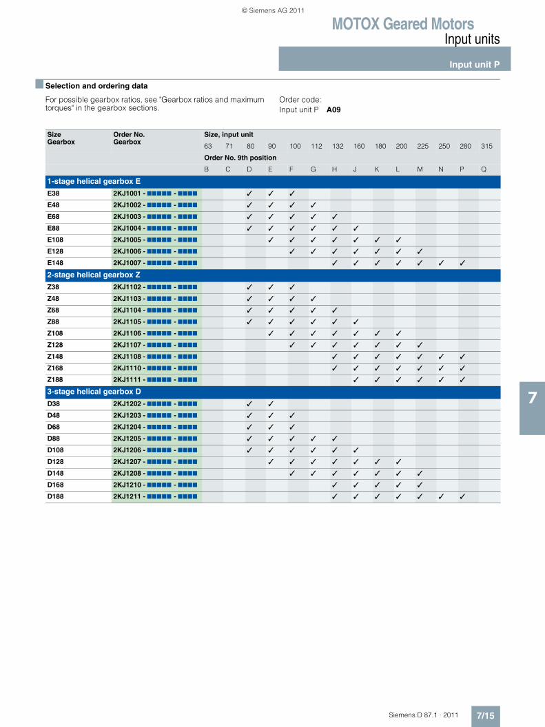
MOTOX Geared MotorsInput units
Input unit P
7/15Siemens D 87.1 · 2011
7
■ Selection and ordering data
For possible gearbox ratios, see "Gearbox ratios and maximum torques" in the gearbox sections.
Order code:Input unit P A09
Size Gearbox
Order No. Gearbox
Size, input unit
63 71 80 90 100 112 132 160 180 200 225 250 280 315
Order No. 9th position
B C D E F G H J K L M N P Q
1-stage helical gearbox E
E38 2KJ1001 - 77777 - 7777 � � �
E48 2KJ1002 - 77777 - 7777 � � � �
E68 2KJ1003 - 77777 - 7777 � � � � �
E88 2KJ1004 - 77777 - 7777 � � � � � �
E108 2KJ1005 - 77777 - 7777 � � � � � � �
E128 2KJ1006 - 77777 - 7777 � � � � � � �
E148 2KJ1007 - 77777 - 7777 � � � � � � �
2-stage helical gearbox Z
Z38 2KJ1102 - 77777 - 7777 � � �
Z48 2KJ1103 - 77777 - 7777 � � � �
Z68 2KJ1104 - 77777 - 7777 � � � � �
Z88 2KJ1105 - 77777 - 7777 � � � � � �
Z108 2KJ1106 - 77777 - 7777 � � � � � � �
Z128 2KJ1107 - 77777 - 7777 � � � � � � �
Z148 2KJ1108 - 77777 - 7777 � � � � � � �
Z168 2KJ1110 - 77777 - 7777 � � � � � � �
Z188 2KJ1111 - 77777 - 7777 � � � � � �
3-stage helical gearbox D
D38 2KJ1202 - 77777 - 7777 � �
D48 2KJ1203 - 77777 - 7777 � � �
D68 2KJ1204 - 77777 - 7777 � � �
D88 2KJ1205 - 77777 - 7777 � � � � �
D108 2KJ1206 - 77777 - 7777 � � � � � �
D128 2KJ1207 - 77777 - 7777 � � � � � � �
D148 2KJ1208 - 77777 - 7777 � � � � � � �
D168 2KJ1210 - 77777 - 7777 � � � � �
D188 2KJ1211 - 77777 - 7777 � � � � � � �
© Siemens AG 2011
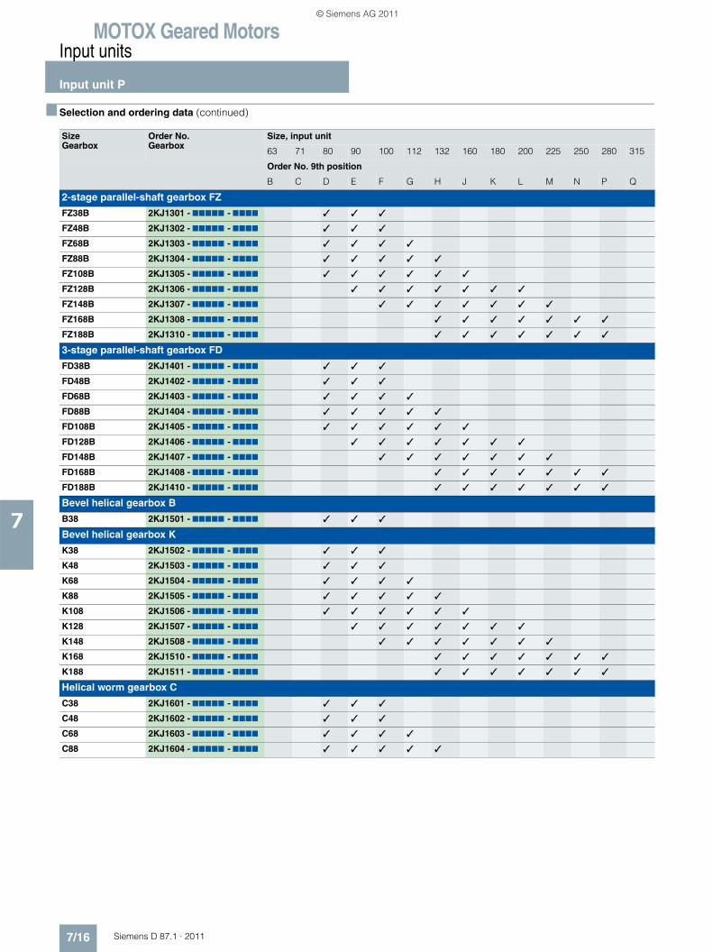
MOTOX Geared MotorsInput units
Input unit P
7/16 Siemens D 87.1 · 2011
7
■ Selection and ordering data (continued)
Size Gearbox
Order No. Gearbox
Size, input unit
63 71 80 90 100 112 132 160 180 200 225 250 280 315
Order No. 9th position
B C D E F G H J K L M N P Q
2-stage parallel-shaft gearbox FZ
FZ38B 2KJ1301 - 77777 - 7777 � � �
FZ48B 2KJ1302 - 77777 - 7777 � � �
FZ68B 2KJ1303 - 77777 - 7777 � � � �
FZ88B 2KJ1304 - 77777 - 7777 � � � � �
FZ108B 2KJ1305 - 77777 - 7777 � � � � � �
FZ128B 2KJ1306 - 77777 - 7777 � � � � � � �
FZ148B 2KJ1307 - 77777 - 7777 � � � � � � �
FZ168B 2KJ1308 - 77777 - 7777 � � � � � � �
FZ188B 2KJ1310 - 77777 - 7777 � � � � � � �
3-stage parallel-shaft gearbox FD
FD38B 2KJ1401 - 77777 - 7777 � � �
FD48B 2KJ1402 - 77777 - 7777 � � �
FD68B 2KJ1403 - 77777 - 7777 � � � �
FD88B 2KJ1404 - 77777 - 7777 � � � � �
FD108B 2KJ1405 - 77777 - 7777 � � � � � �
FD128B 2KJ1406 - 77777 - 7777 � � � � � � �
FD148B 2KJ1407 - 77777 - 7777 � � � � � � �
FD168B 2KJ1408 - 77777 - 7777 � � � � � � �
FD188B 2KJ1410 - 77777 - 7777 � � � � � � �
Bevel helical gearbox B
B38 2KJ1501 - 77777 - 7777 � � �
Bevel helical gearbox K
K38 2KJ1502 - 77777 - 7777 � � �
K48 2KJ1503 - 77777 - 7777 � � �
K68 2KJ1504 - 77777 - 7777 � � � �
K88 2KJ1505 - 77777 - 7777 � � � � �
K108 2KJ1506 - 77777 - 7777 � � � � � �
K128 2KJ1507 - 77777 - 7777 � � � � � � �
K148 2KJ1508 - 77777 - 7777 � � � � � � �
K168 2KJ1510 - 77777 - 7777 � � � � � � �
K188 2KJ1511 - 77777 - 7777 � � � � � � �
Helical worm gearbox C
C38 2KJ1601 - 77777 - 7777 � � �
C48 2KJ1602 - 77777 - 7777 � � �
C68 2KJ1603 - 77777 - 7777 � � � �
C88 2KJ1604 - 77777 - 7777 � � � � �
© Siemens AG 2011
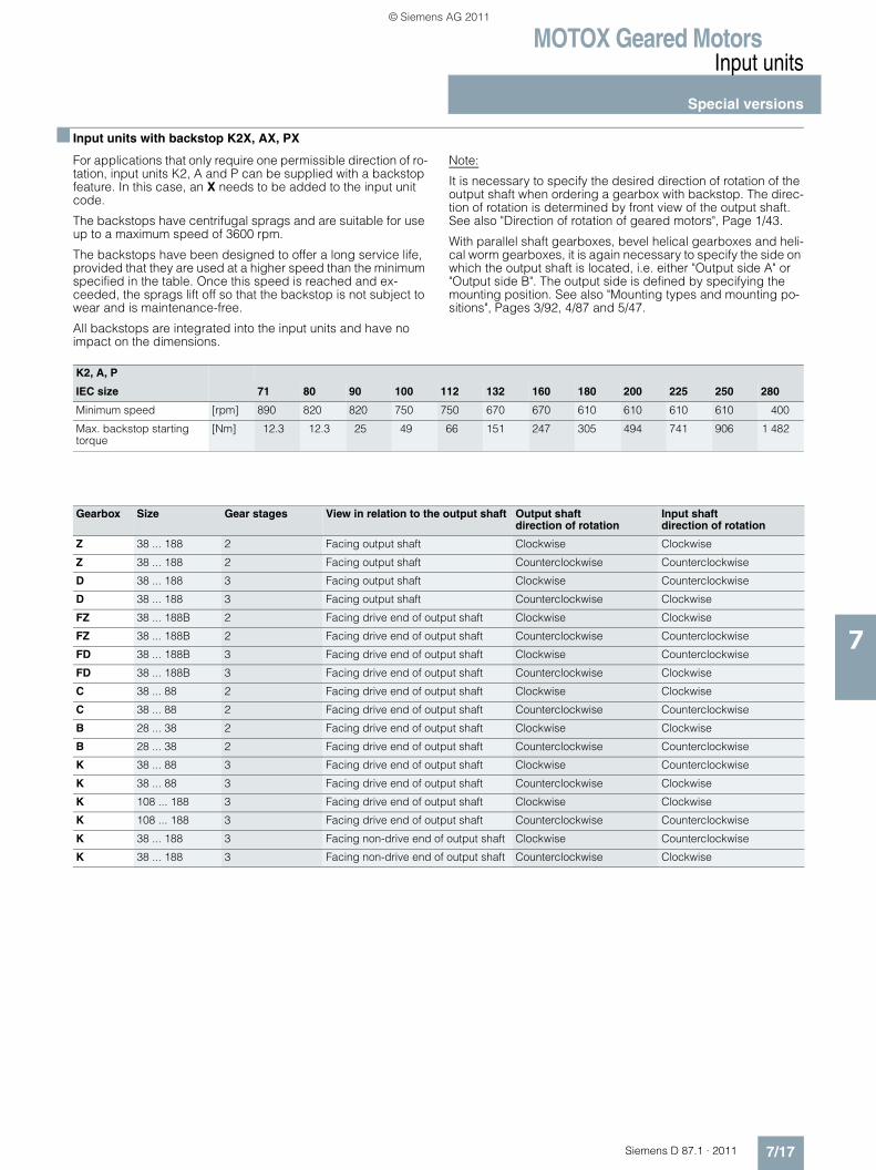
MOTOX Geared MotorsInput units
Special versions
7/17Siemens D 87.1 · 2011
7
■ Input units with backstop K2X, AX, PX
For applications that only require one permissible direction of ro-tation, input units K2, A and P can be supplied with a backstop feature. In this case, an X needs to be added to the input unit code.
The backstops have centrifugal sprags and are suitable for use up to a maximum speed of 3600 rpm.
The backstops have been designed to offer a long service life, provided that they are used at a higher speed than the minimum specified in the table. Once this speed is reached and ex-ceeded, the sprags lift off so that the backstop is not subject to wear and is maintenance-free.
All backstops are integrated into the input units and have no impact on the dimensions.
Note:
It is necessary to specify the desired direction of rotation of the output shaft when ordering a gearbox with backstop. The direc-tion of rotation is determined by front view of the output shaft. See also "Direction of rotation of geared motors", Page 1/43.
With parallel shaft gearboxes, bevel helical gearboxes and heli-cal worm gearboxes, it is again necessary to specify the side on which the output shaft is located, i.e. either "Output side A" or "Output side B". The output side is defined by specifying the mounting position. See also "Mounting types and mounting po-sitions", Pages 3/92, 4/87 and 5/47.
K2, A, P
IEC size 71 80 90 100 112 132 160 180 200 225 250 280
Minimum speed [rpm] 890 820 820 750 750 670 670 610 610 610 610 400
Max. backstop starting torque
[Nm] 12.3 12.3 25 49 66 151 247 305 494 741 906 1 482
Gearbox Size Gear stages View in relation to the output shaft Output shaftdirection of rotation
Input shaftdirection of rotation
Z 38 ... 188 2 Facing output shaft Clockwise Clockwise
Z 38 ... 188 2 Facing output shaft Counterclockwise Counterclockwise
D 38 ... 188 3 Facing output shaft Clockwise Counterclockwise
D 38 ... 188 3 Facing output shaft Counterclockwise Clockwise
FZ 38 ... 188B 2 Facing drive end of output shaft Clockwise Clockwise
FZ 38 ... 188B 2 Facing drive end of output shaft Counterclockwise Counterclockwise
FD 38 ... 188B 3 Facing drive end of output shaft Clockwise Counterclockwise
FD 38 ... 188B 3 Facing drive end of output shaft Counterclockwise Clockwise
C 38 ... 88 2 Facing drive end of output shaft Clockwise Clockwise
C 38 ... 88 2 Facing drive end of output shaft Counterclockwise Counterclockwise
B 28 ... 38 2 Facing drive end of output shaft Clockwise Clockwise
B 28 ... 38 2 Facing drive end of output shaft Counterclockwise Counterclockwise
K 38 ... 88 3 Facing drive end of output shaft Clockwise Counterclockwise
K 38 ... 88 3 Facing drive end of output shaft Counterclockwise Clockwise
K 108 ... 188 3 Facing drive end of output shaft Clockwise Clockwise
K 108 ... 188 3 Facing drive end of output shaft Counterclockwise Counterclockwise
K 38 ... 188 3 Facing non-drive end of output shaft Clockwise Counterclockwise
K 38 ... 188 3 Facing non-drive end of output shaft Counterclockwise Clockwise
© Siemens AG 2011
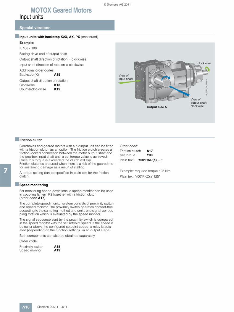
MOTOX Geared MotorsInput units
Special versions
7/18 Siemens D 87.1 · 2011
7
■ Input units with backstop K2X, AX, PX (continued)
Example:
K 108 - 188
Facing drive end of output shaft
Output shaft direction of rotation = clockwise
Input shaft direction of rotation = clockwise
Additional order codes:Backstop (X) A15
Output shaft direction of rotation:Clockwise K18Counterclockwise K19
■ Friction clutch
Gearboxes and geared motors with a K2 input unit can be fitted with a friction clutch as an option. The friction clutch creates a friction-locked connection between the motor output shaft and the gearbox input shaft until a set torque value is achieved. Once this torque is exceeded the clutch will slip.Friction clutches are used when there is a risk of the geared mo-tor sustaining damage as a result of stalling.
A torque setting can be specified in plain text for the friction clutch.
Order code:Friction clutch A17Set torque Y00Plain text: Y00*RKD(a) ....*
Example: required torque 125 Nm
Plain text: Y00*RKD(a)125*
■ Speed monitoring
For monitoring speed deviations, a speed monitor can be used in coupling lantern K2 together with a friction clutch (order code A17).
The complete speed monitor system consists of proximity switch and speed monitor. The proximity switch operates contact-free according to the sampling method and emits one signal per cou-pling rotation which is evaluated by the speed monitor.
The signal sequence sent by the proximity switch is compared in the speed monitor with the set setpoint speed. If the speed is below or above the configured setpoint speed, a relay is actu-ated (depending on the function setting) via an output stage.
Both components can also be obtained separately.
Order code:
Proximity switch A18Speed monitor A19
G_D
087_
EN
_000
64a
View ofinput shaft
Output side A
View ofoutput shaftclockwise
clockwise
© Siemens AG 2011
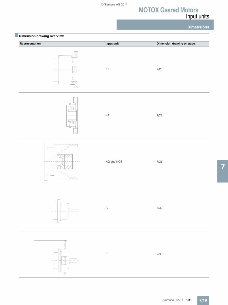
MOTOX Geared MotorsInput units
Dimensions
7/19Siemens D 87.1 · 2011
7
■ Dimension drawing overview
Representation Input unit Dimension drawing on page
K2 7/20
K4 7/23
KQ and KQS 7/28
A 7/30
P 7/33
© Siemens AG 2011
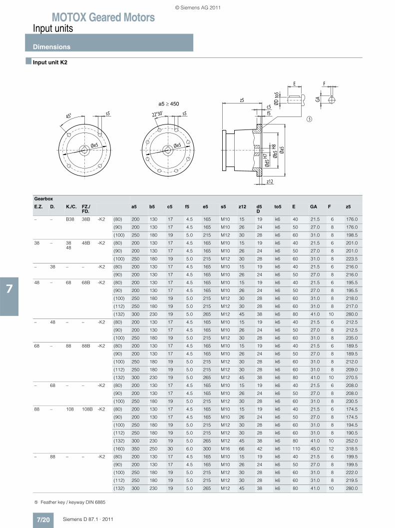
MOTOX Geared MotorsInput units
Dimensions
7/20 Siemens D 87.1 · 2011
7
■ Input unit K2
Gearbox
E.Z. D. K./C. FZ./FD.
a5 b5 c5 f5 e5 s5 z12 d5D
to5 E GA F z5
– – B38 38B -K2 (80) 200 130 17 4.5 165 M10 15 19 k6 40 21.5 6 176.0
(90) 200 130 17 4.5 165 M10 26 24 k6 50 27.0 8 176.0
(100) 250 180 19 5.0 215 M12 30 28 k6 60 31.0 8 198.5
38 – 3848
48B -K2 (80) 200 130 17 4.5 165 M10 15 19 k6 40 21.5 6 201.0
(90) 200 130 17 4.5 165 M10 26 24 k6 50 27.0 8 201.0
(100) 250 180 19 5.0 215 M12 30 28 k6 60 31.0 8 223.5
– 38 – – -K2 (80) 200 130 17 4.5 165 M10 15 19 k6 40 21.5 6 216.0
(90) 200 130 17 4.5 165 M10 26 24 k6 50 27.0 8 216.0
48 – 68 68B -K2 (80) 200 130 17 4.5 165 M10 15 19 k6 40 21.5 6 195.5
(90) 200 130 17 4.5 165 M10 26 24 k6 50 27.0 8 195.5
(100) 250 180 19 5.0 215 M12 30 28 k6 60 31.0 8 218.0
(112) 250 180 19 5.0 215 M12 30 28 k6 60 31.0 8 217.0
(132) 300 230 19 5.0 265 M12 45 38 k6 80 41.0 10 280.0
– 48 – – -K2 (80) 200 130 17 4.5 165 M10 15 19 k6 40 21.5 6 212.5
(90) 200 130 17 4.5 165 M10 26 24 k6 50 27.0 8 212.5
(100) 250 180 19 5.0 215 M12 30 28 k6 60 31.0 8 235.0
68 – 88 88B -K2 (80) 200 130 17 4.5 165 M10 15 19 k6 40 21.5 6 189.5
(90) 200 130 17 4.5 165 M10 26 24 k6 50 27.0 8 189.5
(100) 250 180 19 5.0 215 M12 30 28 k6 60 31.0 8 212.0
(112) 250 180 19 5.0 215 M12 30 28 k6 60 31.0 8 209.0
(132) 300 230 19 5.0 265 M12 45 38 k6 80 41.0 10 270.5
– 68 – – -K2 (80) 200 130 17 4.5 165 M10 15 19 k6 40 21.5 6 208.0
(90) 200 130 17 4.5 165 M10 26 24 k6 50 27.0 8 208.0
(100) 250 180 19 5.0 215 M12 30 28 k6 60 31.0 8 230.5
88 – 108 108B -K2 (80) 200 130 17 4.5 165 M10 15 19 k6 40 21.5 6 174.5
(90) 200 130 17 4.5 165 M10 26 24 k6 50 27.0 8 174.5
(100) 250 180 19 5.0 215 M12 30 28 k6 60 31.0 8 194.5
(112) 250 180 19 5.0 215 M12 30 28 k6 60 31.0 8 190.5
(132) 300 230 19 5.0 265 M12 45 38 k6 80 41.0 10 252.0
(160) 350 250 30 6.0 300 M16 66 42 k6 110 45.0 12 318.5
– 88 – – -K2 (80) 200 130 17 4.5 165 M10 15 19 k6 40 21.5 6 199.5
(90) 200 130 17 4.5 165 M10 26 24 k6 50 27.0 8 199.5
(100) 250 180 19 5.0 215 M12 30 28 k6 60 31.0 8 222.0
(112) 250 180 19 5.0 215 M12 30 28 k6 60 31.0 8 219.5
(132) 300 230 19 5.0 265 M12 45 38 k6 80 41.0 10 280.0
5
F
GA
ØDto
5
E
z12
Øb5
H8Ød
5H7
f5c5
z5
Øa5Øe5Øe5
s522°30's545°
a5 ≥ 450
➄ Feather key / keyway DIN 6885
© Siemens AG 2011

MOTOX Geared MotorsInput units
Dimensions
7/21Siemens D 87.1 · 2011
7
■ Input unit K2 (continued)
Gearbox
E.Z. D. K./C. FZ./FD.
a5 b5 c5 f5 e5 s5 z12 d5D
to5 E GA F z5
108 – 128 128B -K2 (90) 200 130 17 4.5 165 M10 26 24 k6 50 27.0 8 163.0
(100) 250 180 19 5.0 215 M12 30 28 k6 60 31.0 8 182.5
(112) 250 180 19 5.0 215 M12 30 28 k6 60 31.0 8 179.0
(132) 300 230 19 5.0 265 M12 45 38 k6 80 41.0 10 239.5
(160) 350 250 30 6.0 300 M16 66 42 k6 110 45.0 12 307.0
(180) 350 250 25 6.0 300 M16 59 48 k6 110 51.5 14 357.5
(200) 400 300 25 6.0 350 M16 60 55 m6 110 59.0 16 358.5
– 108 – – -K2 (80) 200 130 17 4.5 165 M10 15 19 k6 40 21.5 6 193.5
(90) 200 130 17 4.5 165 M10 26 24 k6 50 27.0 8 193.5
(100) 250 180 19 5.0 215 M12 30 28 k6 60 31.0 8 216.0
(112) 250 180 19 5.0 215 M12 30 28 k6 60 31.0 8 210.5
(132) 300 230 19 5.0 265 M12 45 38 k6 80 41.0 10 272.0
(160) 350 250 30 6.0 300 M16 66 42 k6 110 45.0 12 336.5
128 – 148 148B -K2 (100) 250 180 19 5.0 215 M12 30 28 k6 60 31.0 8 173.0
(112) 250 180 19 5.0 215 M12 30 28 k6 60 31.0 8 168.5
(132) 300 230 19 5.0 265 M12 45 38 k6 80 41.0 10 229.0
(160) 350 250 30 6.0 300 M16 66 42 k6 110 45.0 12 290.5
(180) 350 250 25 6.0 300 M16 59 48 k6 110 51.5 14 344.0
(200) 400 300 25 6.0 350 M16 60 55 m6 110 59.0 16 345.0
(225) 450 350 27 6.0 400 M16 90 60 m6 140 64.0 18 428.5
– 128 – – -K2 (90) 200 130 17 4.5 165 M10 26 24 k6 50 27.0 8 186.5
(100) 250 180 19 5.0 215 M12 30 28 k6 60 31.0 8 209.0
(112) 250 180 19 5.0 215 M12 30 28 k6 60 31.0 8 202.5
(132) 300 230 19 5.0 265 M12 45 38 k6 80 41.0 10 263.0
(160) 350 250 30 6.0 300 M16 66 42 k6 110 45.0 12 327.5
(180) 350 250 25 6.0 300 M16 59 48 k6 110 51.5 14 381.0
(200) 400 300 25 6.0 350 M16 60 55 m6 110 59.0 16 382.0
148 – 168 168B -K2 (132) 300 230 19 5.0 265 M12 45 38 k6 80 41.0 10 221.0
(160) 350 250 30 6.0 300 M16 66 42 k6 110 45.0 12 283.0
(180) 350 250 25 6.0 300 M16 59 48 k6 110 51.5 14 336.5
(200) 400 300 25 6.0 350 M16 60 55 m6 110 59.0 16 337.5
(225) 450 350 27 6.0 400 M16 90 60 m6 140 64.0 18 421.0
(250) 550 450 27 6.0 500 M16 75 65 m6 140 69.0 18 425.5
(280) 550 450 27 7.0 500 M16 51 75 m6 140 79.5 18 469.0
5
F
GA
ØDto
5
E
z12
Øb5
H8Ød
5H7
f5c5
z5
Øa5Øe5Øe5
s522°30's545°
a5 ≥ 450
➄ Feather key / keyway DIN 6885
© Siemens AG 2011
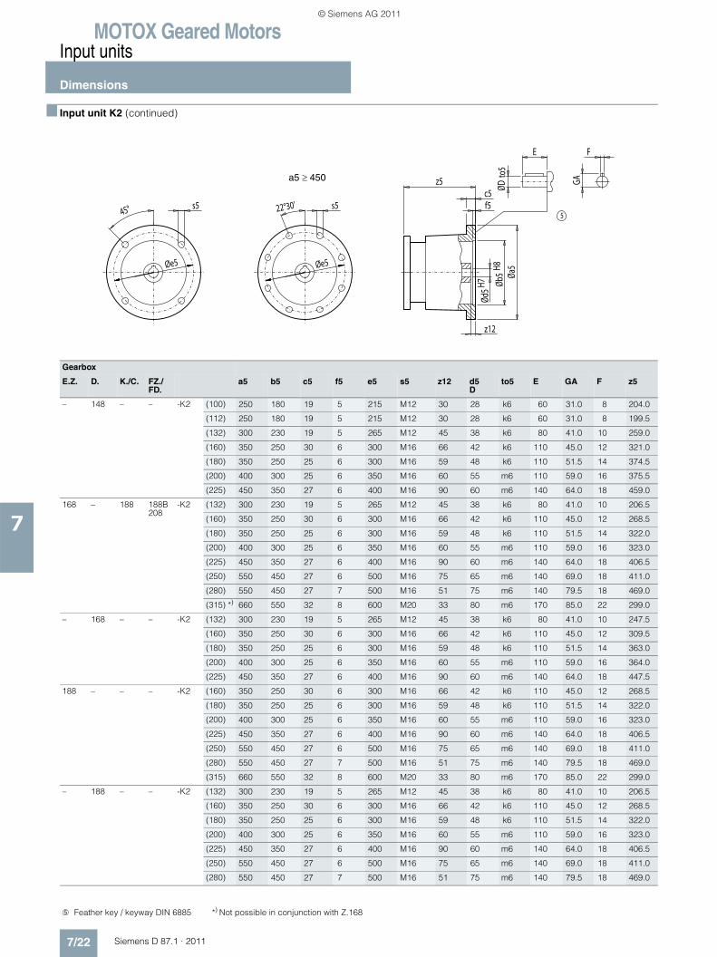
MOTOX Geared MotorsInput units
Dimensions
7/22 Siemens D 87.1 · 2011
7
■ Input unit K2 (continued)
Gearbox
E.Z. D. K./C. FZ./FD.
a5 b5 c5 f5 e5 s5 z12 d5D
to5 E GA F z5
– 148 – – -K2 (100) 250 180 19 5 215 M12 30 28 k6 60 31.0 8 204.0
(112) 250 180 19 5 215 M12 30 28 k6 60 31.0 8 199.5
(132) 300 230 19 5 265 M12 45 38 k6 80 41.0 10 259.0
(160) 350 250 30 6 300 M16 66 42 k6 110 45.0 12 321.0
(180) 350 250 25 6 300 M16 59 48 k6 110 51.5 14 374.5
(200) 400 300 25 6 350 M16 60 55 m6 110 59.0 16 375.5
(225) 450 350 27 6 400 M16 90 60 m6 140 64.0 18 459.0
168 – 188 188B208
-K2 (132) 300 230 19 5 265 M12 45 38 k6 80 41.0 10 206.5
(160) 350 250 30 6 300 M16 66 42 k6 110 45.0 12 268.5
(180) 350 250 25 6 300 M16 59 48 k6 110 51.5 14 322.0
(200) 400 300 25 6 350 M16 60 55 m6 110 59.0 16 323.0
(225) 450 350 27 6 400 M16 90 60 m6 140 64.0 18 406.5
(250) 550 450 27 6 500 M16 75 65 m6 140 69.0 18 411.0
(280) 550 450 27 7 500 M16 51 75 m6 140 79.5 18 469.0
(315) *) 660 550 32 8 600 M20 33 80 m6 170 85.0 22 299.0
– 168 – – -K2 (132) 300 230 19 5 265 M12 45 38 k6 80 41.0 10 247.5
(160) 350 250 30 6 300 M16 66 42 k6 110 45.0 12 309.5
(180) 350 250 25 6 300 M16 59 48 k6 110 51.5 14 363.0
(200) 400 300 25 6 350 M16 60 55 m6 110 59.0 16 364.0
(225) 450 350 27 6 400 M16 90 60 m6 140 64.0 18 447.5
188 – – – -K2 (160) 350 250 30 6 300 M16 66 42 k6 110 45.0 12 268.5
(180) 350 250 25 6 300 M16 59 48 k6 110 51.5 14 322.0
(200) 400 300 25 6 350 M16 60 55 m6 110 59.0 16 323.0
(225) 450 350 27 6 400 M16 90 60 m6 140 64.0 18 406.5
(250) 550 450 27 6 500 M16 75 65 m6 140 69.0 18 411.0
(280) 550 450 27 7 500 M16 51 75 m6 140 79.5 18 469.0
(315) 660 550 32 8 600 M20 33 80 m6 170 85.0 22 299.0
– 188 – – -K2 (132) 300 230 19 5 265 M12 45 38 k6 80 41.0 10 206.5
(160) 350 250 30 6 300 M16 66 42 k6 110 45.0 12 268.5
(180) 350 250 25 6 300 M16 59 48 k6 110 51.5 14 322.0
(200) 400 300 25 6 350 M16 60 55 m6 110 59.0 16 323.0
(225) 450 350 27 6 400 M16 90 60 m6 140 64.0 18 406.5
(250) 550 450 27 6 500 M16 75 65 m6 140 69.0 18 411.0
(280) 550 450 27 7 500 M16 51 75 m6 140 79.5 18 469.0
5
F
GA
ØDto
5
E
z12
Øb5
H8Ød
5H7
f5c5
z5
Øa5Øe5Øe5
s522°30's545°
a5 ≥ 450
➄ Feather key / keyway DIN 6885 *) Not possible in conjunction with Z.168
© Siemens AG 2011
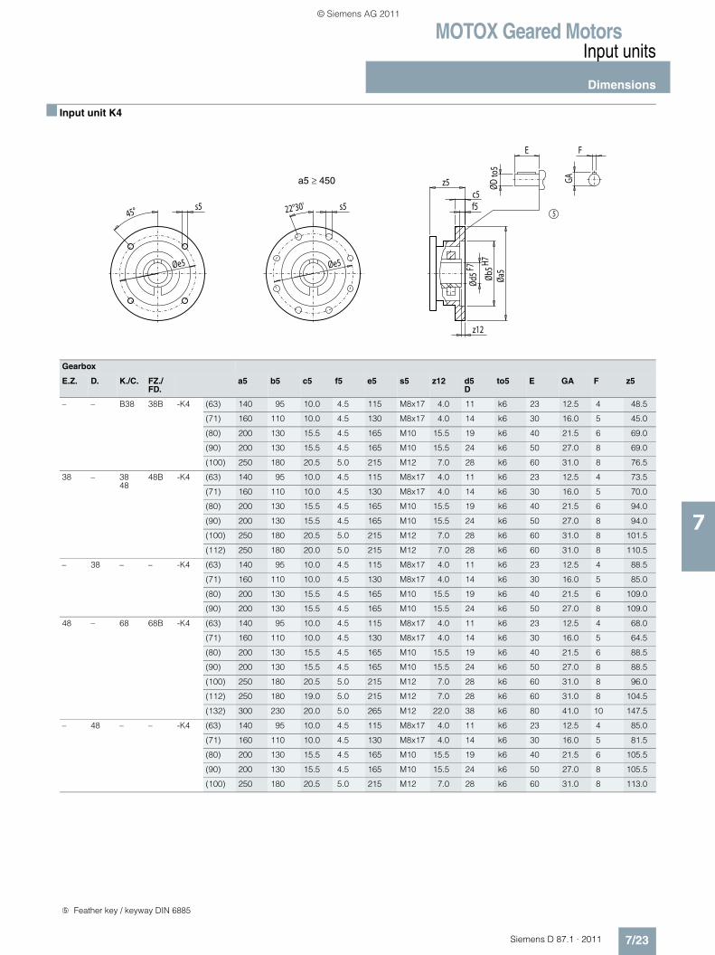
MOTOX Geared MotorsInput units
Dimensions
7/23Siemens D 87.1 · 2011
7
■ Input unit K4
Gearbox
E.Z. D. K./C. FZ./FD.
a5 b5 c5 f5 e5 s5 z12 d5D
to5 E GA F z5
– – B38 38B -K4 (63) 140 95 10.0 4.5 115 M8x17 4.0 11 k6 23 12.5 4 48.5
(71) 160 110 10.0 4.5 130 M8x17 4.0 14 k6 30 16.0 5 45.0
(80) 200 130 15.5 4.5 165 M10 15.5 19 k6 40 21.5 6 69.0
(90) 200 130 15.5 4.5 165 M10 15.5 24 k6 50 27.0 8 69.0
(100) 250 180 20.5 5.0 215 M12 7.0 28 k6 60 31.0 8 76.5
38 – 3848
48B -K4 (63) 140 95 10.0 4.5 115 M8x17 4.0 11 k6 23 12.5 4 73.5
(71) 160 110 10.0 4.5 130 M8x17 4.0 14 k6 30 16.0 5 70.0
(80) 200 130 15.5 4.5 165 M10 15.5 19 k6 40 21.5 6 94.0
(90) 200 130 15.5 4.5 165 M10 15.5 24 k6 50 27.0 8 94.0
(100) 250 180 20.5 5.0 215 M12 7.0 28 k6 60 31.0 8 101.5
(112) 250 180 20.0 5.0 215 M12 7.0 28 k6 60 31.0 8 110.5
– 38 – – -K4 (63) 140 95 10.0 4.5 115 M8x17 4.0 11 k6 23 12.5 4 88.5
(71) 160 110 10.0 4.5 130 M8x17 4.0 14 k6 30 16.0 5 85.0
(80) 200 130 15.5 4.5 165 M10 15.5 19 k6 40 21.5 6 109.0
(90) 200 130 15.5 4.5 165 M10 15.5 24 k6 50 27.0 8 109.0
48 – 68 68B -K4 (63) 140 95 10.0 4.5 115 M8x17 4.0 11 k6 23 12.5 4 68.0
(71) 160 110 10.0 4.5 130 M8x17 4.0 14 k6 30 16.0 5 64.5
(80) 200 130 15.5 4.5 165 M10 15.5 19 k6 40 21.5 6 88.5
(90) 200 130 15.5 4.5 165 M10 15.5 24 k6 50 27.0 8 88.5
(100) 250 180 20.5 5.0 215 M12 7.0 28 k6 60 31.0 8 96.0
(112) 250 180 19.0 5.0 215 M12 7.0 28 k6 60 31.0 8 104.5
(132) 300 230 20.0 5.0 265 M12 22.0 38 k6 80 41.0 10 147.5
– 48 – – -K4 (63) 140 95 10.0 4.5 115 M8x17 4.0 11 k6 23 12.5 4 85.0
(71) 160 110 10.0 4.5 130 M8x17 4.0 14 k6 30 16.0 5 81.5
(80) 200 130 15.5 4.5 165 M10 15.5 19 k6 40 21.5 6 105.5
(90) 200 130 15.5 4.5 165 M10 15.5 24 k6 50 27.0 8 105.5
(100) 250 180 20.5 5.0 215 M12 7.0 28 k6 60 31.0 8 113.0
5
z5
Øe5
s522°30's5
Øe5
45°
F
GA
ØDto
5
E
Øa5
z12
Ød5
F7
c5f5
Øb5H7
a5 ≥ 450
➄ Feather key / keyway DIN 6885
© Siemens AG 2011
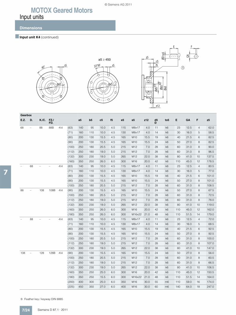
MOTOX Geared MotorsInput units
Dimensions
7/24 Siemens D 87.1 · 2011
7
■ Input unit K4 (continued)
Gearbox
E.Z. D. K./C. FZ./FD.
a5 b5 c5 f5 e5 s5 z12 d5D
to5 E GA F z5
68 – 88 88B -K4 (63) 140 95 10.0 4.5 115 M8x17 4.0 11 k6 23 12.5 4 62.0
(71) 160 110 10.0 4.5 130 M8x17 4.0 14 k6 30 16.0 5 58.5
(80) 200 130 15.5 4.5 165 M10 15.5 19 k6 40 21.5 6 82.5
(90) 200 130 15.5 4.5 165 M10 15.5 24 k6 50 27.0 8 82.5
(100) 250 180 20.5 5.0 215 M12 7.0 28 k6 60 31.0 8 90.0
(112) 250 180 19.0 5.0 215 M12 7.0 28 k6 60 31.0 8 96.5
(132) 300 230 19.0 5.0 265 M12 22.0 38 k6 80 41.0 10 137.5
(160) 350 250 26.0 6.0 300 M16 20.0 42 k6 110 45.0 12 178.5
– 68 – – -K4 (63) 140 95 10.0 4.5 115 M8x17 4.0 11 k6 23 12.5 4 80.5
(71) 160 110 10.0 4.5 130 M8x17 4.0 14 k6 30 16.0 5 77.0
(80) 200 130 15.5 4.5 165 M10 15.5 19 k6 40 21.5 6 101.0
(90) 200 130 15.5 4.5 165 M10 15.5 24 k6 50 27.0 8 101.0
(100) 250 180 20.5 5.0 215 M12 7.0 28 k6 60 31.0 8 108.5
88 – 108 108B -K4 (90) 200 130 15.5 4.5 165 M10 15.5 24 k6 50 27.0 8 67.5
(100) 250 180 20.5 5.0 215 M12 7.0 28 k6 60 31.0 8 72.5
(112) 250 180 19.0 5.0 215 M12 7.0 28 k6 60 31.0 8 78.0
(132) 300 230 19.0 5.0 265 M12 22.0 38 k6 80 41.0 10 119.0
(160) 350 250 26.0 6.0 300 M16 20.0 42 k6 110 45.0 12 162.0
(180) 350 250 26.0 6.0 300 M16x22 21.0 48 k6 110 51.5 14 179.0
– 88 – – -K4 (63) 140 95 10.0 4.5 115 M8x17 4.0 11 k6 23 12.5 4 72.0
(71) 160 110 10.0 4.5 130 M8x17 4.0 14 k6 30 16.0 5 68.5
(80) 200 130 15.5 4.5 165 M10 15.5 19 k6 40 21.5 6 92.5
(90) 200 130 15.5 4.5 165 M10 15.5 24 k6 50 27.0 8 92.5
(100) 250 180 20.5 5.0 215 M12 7.0 28 k6 60 31.0 8 100.0
(112) 250 180 19.0 5.0 215 M12 7.0 28 k6 60 31.0 8 107.0
(132) 300 230 19.0 5.0 265 M12 22.0 38 k6 80 41.0 10 147.0
108 – 128 128B -K4 (90) 200 130 15.5 4.5 165 M10 15.5 24 k6 50 27.0 8 56.0
(100) 250 180 20.5 5.0 215 M12 7.0 28 k6 60 31.0 8 60.5
(112) 250 180 19.0 5.0 215 M12 7.0 28 k6 60 31.0 8 66.5
(132) 300 230 19.0 5.0 265 M12 22.0 38 k6 80 41.0 10 106.5
(160) 350 250 25.0 6.0 300 M16 20.0 42 k6 110 45.0 12 150.5
(180) 350 250 15.5 6.0 300 M16x22 21.0 48 k6 110 51.5 14 164.0
(200) 400 300 25.0 6.0 350 M16 30.0 55 m6 110 59.0 16 174.0
(225) 450 350 27.0 6.0 400 M16 30.0 60 m6 140 64.0 18 247.0
5
z5
Øe5
s522°30's5
Øe5
45°
F
GA
ØDto
5
E
Øa5
z12
Ød5
F7
c5f5
Øb5H7
a5 ≥ 450
➄ Feather key / keyway DIN 6885
© Siemens AG 2011
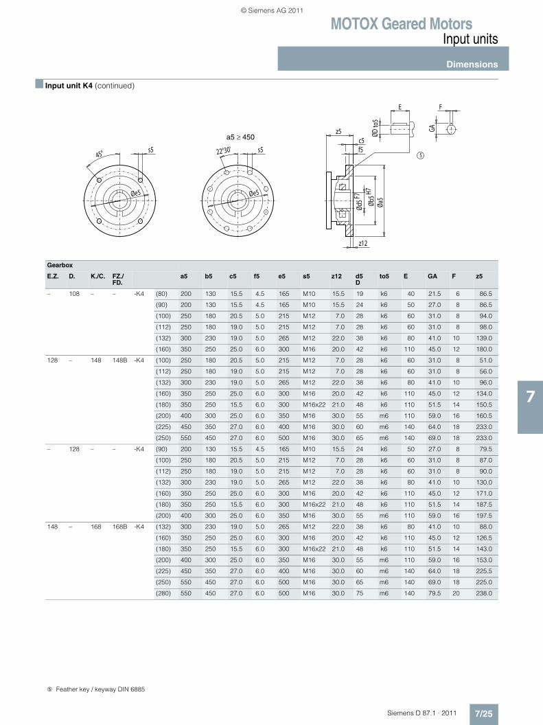
MOTOX Geared MotorsInput units
Dimensions
7/25Siemens D 87.1 · 2011
7
■ Input unit K4 (continued)
Gearbox
E.Z. D. K./C. FZ./FD.
a5 b5 c5 f5 e5 s5 z12 d5D
to5 E GA F z5
– 108 – – -K4 (80) 200 130 15.5 4.5 165 M10 15.5 19 k6 40 21.5 6 86.5
(90) 200 130 15.5 4.5 165 M10 15.5 24 k6 50 27.0 8 86.5
(100) 250 180 20.5 5.0 215 M12 7.0 28 k6 60 31.0 8 94.0
(112) 250 180 19.0 5.0 215 M12 7.0 28 k6 60 31.0 8 98.0
(132) 300 230 19.0 5.0 265 M12 22.0 38 k6 80 41.0 10 139.0
(160) 350 250 25.0 6.0 300 M16 20.0 42 k6 110 45.0 12 180.0
128 – 148 148B -K4 (100) 250 180 20.5 5.0 215 M12 7.0 28 k6 60 31.0 8 51.0
(112) 250 180 19.0 5.0 215 M12 7.0 28 k6 60 31.0 8 56.0
(132) 300 230 19.0 5.0 265 M12 22.0 38 k6 80 41.0 10 96.0
(160) 350 250 25.0 6.0 300 M16 20.0 42 k6 110 45.0 12 134.0
(180) 350 250 15.5 6.0 300 M16x22 21.0 48 k6 110 51.5 14 150.5
(200) 400 300 25.0 6.0 350 M16 30.0 55 m6 110 59.0 16 160.5
(225) 450 350 27.0 6.0 400 M16 30.0 60 m6 140 64.0 18 233.0
(250) 550 450 27.0 6.0 500 M16 30.0 65 m6 140 69.0 18 233.0
– 128 – – -K4 (90) 200 130 15.5 4.5 165 M10 15.5 24 k6 50 27.0 8 79.5
(100) 250 180 20.5 5.0 215 M12 7.0 28 k6 60 31.0 8 87.0
(112) 250 180 19.0 5.0 215 M12 7.0 28 k6 60 31.0 8 90.0
(132) 300 230 19.0 5.0 265 M12 22.0 38 k6 80 41.0 10 130.0
(160) 350 250 25.0 6.0 300 M16 20.0 42 k6 110 45.0 12 171.0
(180) 350 250 15.5 6.0 300 M16x22 21.0 48 k6 110 51.5 14 187.5
(200) 400 300 25.0 6.0 350 M16 30.0 55 m6 110 59.0 16 197.5
148 – 168 168B -K4 (132) 300 230 19.0 5.0 265 M12 22.0 38 k6 80 41.0 10 88.0
(160) 350 250 25.0 6.0 300 M16 20.0 42 k6 110 45.0 12 126.5
(180) 350 250 15.5 6.0 300 M16x22 21.0 48 k6 110 51.5 14 143.0
(200) 400 300 25.0 6.0 350 M16 30.0 55 m6 110 59.0 16 153.0
(225) 450 350 27.0 6.0 400 M16 30.0 60 m6 140 64.0 18 225.5
(250) 550 450 27.0 6.0 500 M16 30.0 65 m6 140 69.0 18 225.0
(280) 550 450 27.0 6.0 500 M16 30.0 75 m6 140 79.5 20 238.0
5
z5
Øe5
s522°30's5
Øe5
45°
F
GA
ØDto
5
E
Øa5
z12
Ød5
F7
c5f5
Øb5H7
a5 ≥ 450
➄ Feather key / keyway DIN 6885
© Siemens AG 2011
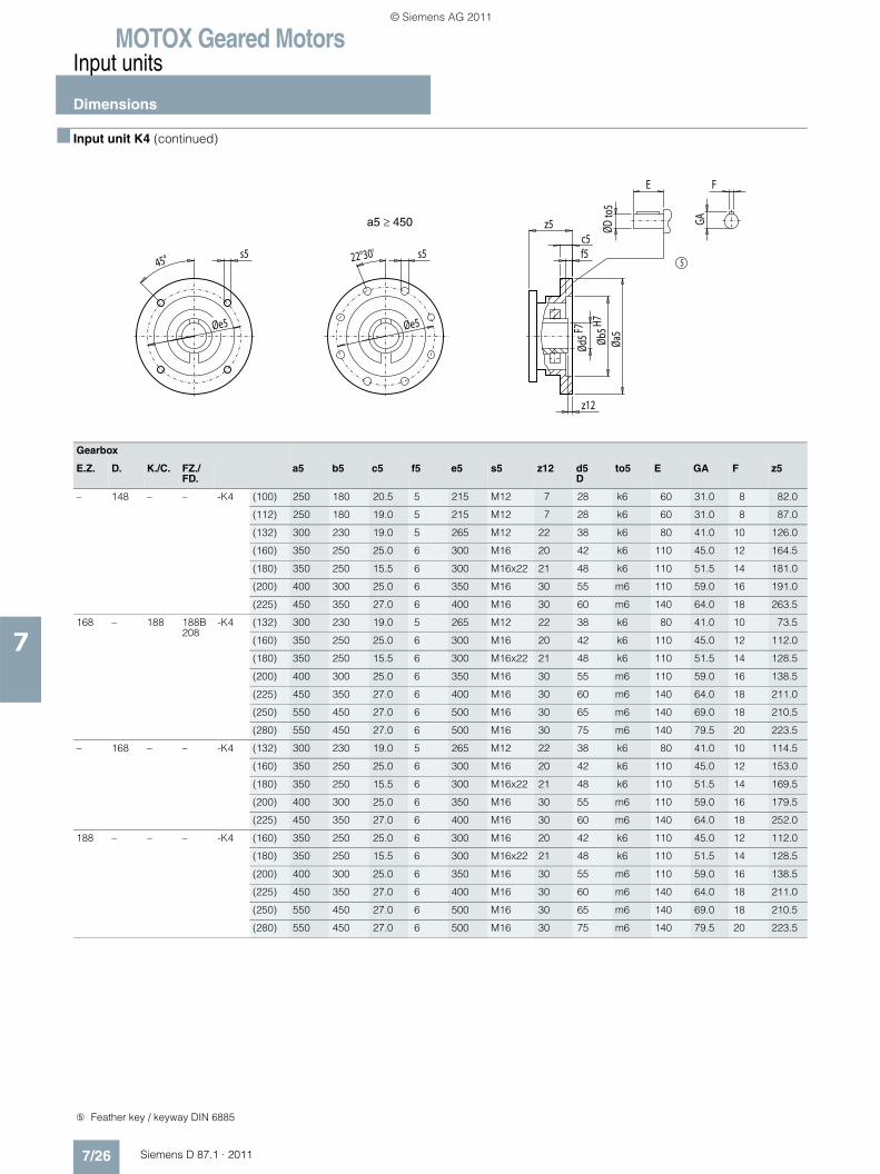
MOTOX Geared MotorsInput units
Dimensions
7/26 Siemens D 87.1 · 2011
7
■ Input unit K4 (continued)
Gearbox
E.Z. D. K./C. FZ./FD.
a5 b5 c5 f5 e5 s5 z12 d5D
to5 E GA F z5
– 148 – – -K4 (100) 250 180 20.5 5 215 M12 7 28 k6 60 31.0 8 82.0
(112) 250 180 19.0 5 215 M12 7 28 k6 60 31.0 8 87.0
(132) 300 230 19.0 5 265 M12 22 38 k6 80 41.0 10 126.0
(160) 350 250 25.0 6 300 M16 20 42 k6 110 45.0 12 164.5
(180) 350 250 15.5 6 300 M16x22 21 48 k6 110 51.5 14 181.0
(200) 400 300 25.0 6 350 M16 30 55 m6 110 59.0 16 191.0
(225) 450 350 27.0 6 400 M16 30 60 m6 140 64.0 18 263.5
168 – 188 188B208
-K4 (132) 300 230 19.0 5 265 M12 22 38 k6 80 41.0 10 73.5
(160) 350 250 25.0 6 300 M16 20 42 k6 110 45.0 12 112.0
(180) 350 250 15.5 6 300 M16x22 21 48 k6 110 51.5 14 128.5
(200) 400 300 25.0 6 350 M16 30 55 m6 110 59.0 16 138.5
(225) 450 350 27.0 6 400 M16 30 60 m6 140 64.0 18 211.0
(250) 550 450 27.0 6 500 M16 30 65 m6 140 69.0 18 210.5
(280) 550 450 27.0 6 500 M16 30 75 m6 140 79.5 20 223.5
– 168 – – -K4 (132) 300 230 19.0 5 265 M12 22 38 k6 80 41.0 10 114.5
(160) 350 250 25.0 6 300 M16 20 42 k6 110 45.0 12 153.0
(180) 350 250 15.5 6 300 M16x22 21 48 k6 110 51.5 14 169.5
(200) 400 300 25.0 6 350 M16 30 55 m6 110 59.0 16 179.5
(225) 450 350 27.0 6 400 M16 30 60 m6 140 64.0 18 252.0
188 – – – -K4 (160) 350 250 25.0 6 300 M16 20 42 k6 110 45.0 12 112.0
(180) 350 250 15.5 6 300 M16x22 21 48 k6 110 51.5 14 128.5
(200) 400 300 25.0 6 350 M16 30 55 m6 110 59.0 16 138.5
(225) 450 350 27.0 6 400 M16 30 60 m6 140 64.0 18 211.0
(250) 550 450 27.0 6 500 M16 30 65 m6 140 69.0 18 210.5
(280) 550 450 27.0 6 500 M16 30 75 m6 140 79.5 20 223.5
5
z5
Øe5
s522°30's5
Øe5
45°
F
GA
ØDto
5
E
Øa5
z12
Ød5
F7
c5f5
Øb5H7
a5 ≥ 450
➄ Feather key / keyway DIN 6885
© Siemens AG 2011
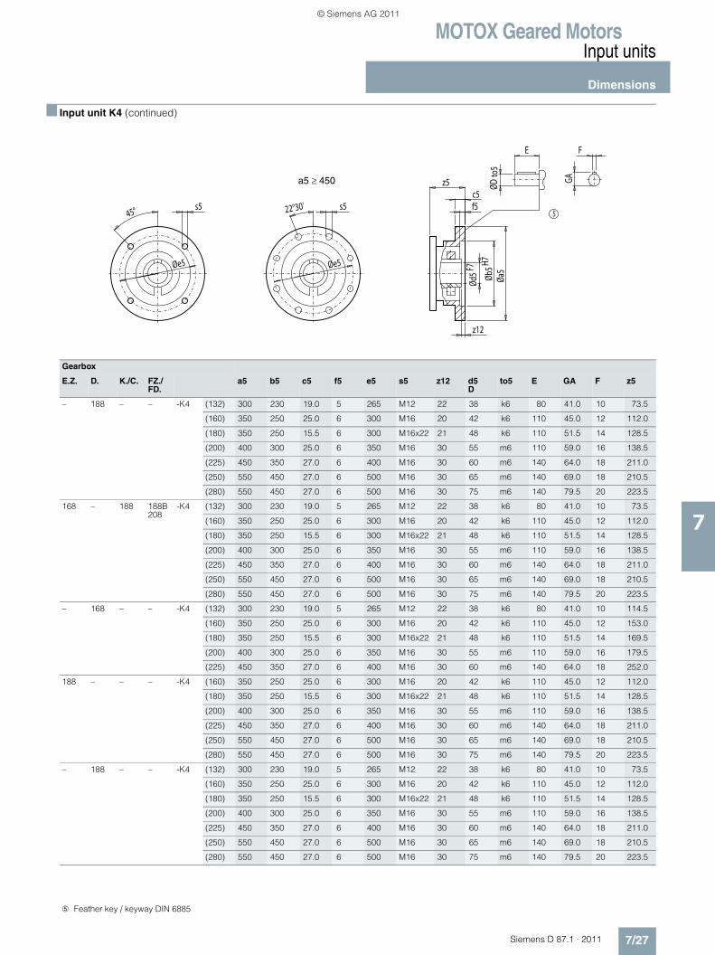
MOTOX Geared MotorsInput units
Dimensions
7/27Siemens D 87.1 · 2011
7
■ Input unit K4 (continued)
Gearbox
E.Z. D. K./C. FZ./FD.
a5 b5 c5 f5 e5 s5 z12 d5D
to5 E GA F z5
– 188 – – -K4 (132) 300 230 19.0 5 265 M12 22 38 k6 80 41.0 10 73.5
(160) 350 250 25.0 6 300 M16 20 42 k6 110 45.0 12 112.0
(180) 350 250 15.5 6 300 M16x22 21 48 k6 110 51.5 14 128.5
(200) 400 300 25.0 6 350 M16 30 55 m6 110 59.0 16 138.5
(225) 450 350 27.0 6 400 M16 30 60 m6 140 64.0 18 211.0
(250) 550 450 27.0 6 500 M16 30 65 m6 140 69.0 18 210.5
(280) 550 450 27.0 6 500 M16 30 75 m6 140 79.5 20 223.5
168 – 188 188B208
-K4 (132) 300 230 19.0 5 265 M12 22 38 k6 80 41.0 10 73.5
(160) 350 250 25.0 6 300 M16 20 42 k6 110 45.0 12 112.0
(180) 350 250 15.5 6 300 M16x22 21 48 k6 110 51.5 14 128.5
(200) 400 300 25.0 6 350 M16 30 55 m6 110 59.0 16 138.5
(225) 450 350 27.0 6 400 M16 30 60 m6 140 64.0 18 211.0
(250) 550 450 27.0 6 500 M16 30 65 m6 140 69.0 18 210.5
(280) 550 450 27.0 6 500 M16 30 75 m6 140 79.5 20 223.5
– 168 – – -K4 (132) 300 230 19.0 5 265 M12 22 38 k6 80 41.0 10 114.5
(160) 350 250 25.0 6 300 M16 20 42 k6 110 45.0 12 153.0
(180) 350 250 15.5 6 300 M16x22 21 48 k6 110 51.5 14 169.5
(200) 400 300 25.0 6 350 M16 30 55 m6 110 59.0 16 179.5
(225) 450 350 27.0 6 400 M16 30 60 m6 140 64.0 18 252.0
188 – – – -K4 (160) 350 250 25.0 6 300 M16 20 42 k6 110 45.0 12 112.0
(180) 350 250 15.5 6 300 M16x22 21 48 k6 110 51.5 14 128.5
(200) 400 300 25.0 6 350 M16 30 55 m6 110 59.0 16 138.5
(225) 450 350 27.0 6 400 M16 30 60 m6 140 64.0 18 211.0
(250) 550 450 27.0 6 500 M16 30 65 m6 140 69.0 18 210.5
(280) 550 450 27.0 6 500 M16 30 75 m6 140 79.5 20 223.5
– 188 – – -K4 (132) 300 230 19.0 5 265 M12 22 38 k6 80 41.0 10 73.5
(160) 350 250 25.0 6 300 M16 20 42 k6 110 45.0 12 112.0
(180) 350 250 15.5 6 300 M16x22 21 48 k6 110 51.5 14 128.5
(200) 400 300 25.0 6 350 M16 30 55 m6 110 59.0 16 138.5
(225) 450 350 27.0 6 400 M16 30 60 m6 140 64.0 18 211.0
(250) 550 450 27.0 6 500 M16 30 65 m6 140 69.0 18 210.5
(280) 550 450 27.0 6 500 M16 30 75 m6 140 79.5 20 223.5
5
z5
Øe5
s522°30's5
Øe5
45°
F
GA
ØDto
5
E
Øa5
z12
Ød5
F7
c5f5
Øb5H7
a5 ≥ 450
➄ Feather key / keyway DIN 6885
© Siemens AG 2011
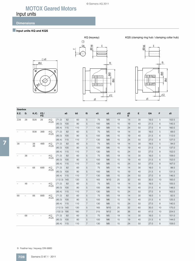
MOTOX Geared MotorsInput units
Dimensions
7/28 Siemens D 87.1 · 2011
7
■ Input units KQ and KQS
Gearbox
E.Z. D. K./C. FZ./FD.
a5 b5 f5 e5 s5 z12 d5D
E GA F z5
Z28 28 B28 28 -KQ-KQS
(71.2) 82 60 5 75 M5 19 14 30 16.0 5 102.5
(80.3) 100 80 5 100 M6 15 19 40 21.5 6 145.5
(90.4) 115 110 7 130 M8 15 24 50 27.0 8 160.5
– – B38 38B -KQ-KQS
(71.2) 82 60 5 75 M5 19 14 30 16.0 5 69.0
(80.3) 100 80 5 100 M6 15 19 40 21.5 6 112.0
(90.4) 115 110 7 130 M8 15 24 50 27.0 8 127.0
38 – 3848
48B -KQ-KQS
(71.2) 82 60 5 75 M5 19 14 30 16.0 5 94.0
(80.3) 100 80 5 100 M6 15 19 40 21.5 6 137.0
(90.4) 115 110 7 130 M8 15 24 50 27.0 8 152.0
– 38 – – -KQ-KQS
(71.2) 82 60 5 75 M5 19 14 30 16.0 5 109.0
(80.3) 100 80 5 100 M6 15 19 40 21.5 6 152.0
(90.4) 115 110 7 130 M8 15 24 50 27.0 8 167.0
48 – 68 68B -KQ-KQS
(71.2) 82 60 5 75 M5 19 14 30 16.0 5 88.5
(80.3) 100 80 5 100 M6 15 19 40 21.5 6 131.5
(90.4) 115 110 7 130 M8 15 24 50 27.0 8 146.5
(112.3) 140 130 5 165 M10 25 32 60 35.0 10 183.0
– 48 – – -KQ-KQS
(71.2) 82 60 5 75 M5 19 14 30 16.0 5 105.5
(80.3) 100 80 5 100 M6 15 19 40 21.5 6 148.5
(90.4) 115 110 7 130 M8 15 24 50 27.0 8 163.5
68 – 88 88B -KQ-KQS
(71.2) 82 60 5 75 M5 19 14 30 16.0 5 82.5
(80.3) 100 80 5 100 M6 15 19 40 21.5 6 125.5
(90.4) 115 110 7 130 M8 15 24 50 27.0 8 140.5
(112.3) 140 130 5 165 M10 25 32 60 35.0 10 175.0
(132.3) 190 180 7 215 M12 30 38 80 41.0 10 224.5
– 68 – – -KQ-KQS
(71.2) 82 60 5 75 M5 19 14 30 16.0 5 101.0
(80.3) 100 80 5 100 M6 15 19 40 21.5 6 144.0
(90.4) 115 110 7 130 M8 15 24 50 27.0 8 159.0
5
z5
f5
z12
z5
Øs5
Øe5
ØDk6
a5
GA
F
z12
Øb5
Øb5
E
Ød5
Ød5
ØDk6 E
f5
KQ (keyway) KQS (clamping ring hub / clamping collar hub)
➄ Feather key / keyway DIN 6885
© Siemens AG 2011
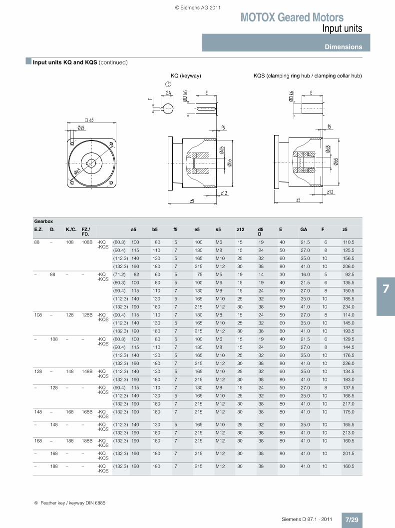
MOTOX Geared MotorsInput units
Dimensions
7/29Siemens D 87.1 · 2011
7
■ Input units KQ and KQS (continued)
Gearbox
E.Z. D. K./C. FZ./FD.
a5 b5 f5 e5 s5 z12 d5D
E GA F z5
88 – 108 108B -KQ-KQS
(80.3) 100 80 5 100 M6 15 19 40 21.5 6 110.5
(90.4) 115 110 7 130 M8 15 24 50 27.0 8 125.5
(112.3) 140 130 5 165 M10 25 32 60 35.0 10 156.5
(132.3) 190 180 7 215 M12 30 38 80 41.0 10 206.0
– 88 – – -KQ-KQS
(71.2) 82 60 5 75 M5 19 14 30 16.0 5 92.5
(80.3) 100 80 5 100 M6 15 19 40 21.5 6 135.5
(90.4) 115 110 7 130 M8 15 24 50 27.0 8 150.5
(112.3) 140 130 5 165 M10 25 32 60 35.0 10 185.5
(132.3) 190 180 7 215 M12 30 38 80 41.0 10 234.0
108 – 128 128B -KQ-KQS
(90.4) 115 110 7 130 M8 15 24 50 27.0 8 114.0
(112.3) 140 130 5 165 M10 25 32 60 35.0 10 145.0
(132.3) 190 180 7 215 M12 30 38 80 41.0 10 193.5
– 108 – – -KQ-KQS
(80.3) 100 80 5 100 M6 15 19 40 21.5 6 129.5
(90.4) 115 110 7 130 M8 15 24 50 27.0 8 144.5
(112.3) 140 130 5 165 M10 25 32 60 35.0 10 176.5
(132.3) 190 180 7 215 M12 30 38 80 41.0 10 226.0
128 – 148 148B -KQ-KQS
(112.3) 140 130 5 165 M10 25 32 60 35.0 10 134.5
(132.3) 190 180 7 215 M12 30 38 80 41.0 10 183.0
– 128 – – -KQ-KQS
(90.4) 115 110 7 130 M8 15 24 50 27.0 8 137.5
(112.3) 140 130 5 165 M10 25 32 60 35.0 10 168.5
(132.3) 190 180 7 215 M12 30 38 80 41.0 10 217.0
148 – 168 168B -KQ-KQS
(132.3) 190 180 7 215 M12 30 38 80 41.0 10 175.0
– 148 – – -KQ-KQS
(112.3) 140 130 5 165 M10 25 32 60 35.0 10 165.5
(132.3) 190 180 7 215 M12 30 38 80 41.0 10 213.0
168 – 188 188B -KQ-KQS
(132.3) 190 180 7 215 M12 30 38 80 41.0 10 160.5
– 168 – – -KQ-KQS
(132.3) 190 180 7 215 M12 30 38 80 41.0 10 201.5
– 188 – – -KQ-KQS
(132.3) 190 180 7 215 M12 30 38 80 41.0 10 160.5
5
z5
f5
z12
z5
Øs5
Øe5
ØDk6
a5
GA
F
z12
Øb5
Øb5
E
Ød5
Ød5
ØDk6 E
f5
KQ (keyway) KQS (clamping ring hub / clamping collar hub)
➄ Feather key / keyway DIN 6885
© Siemens AG 2011
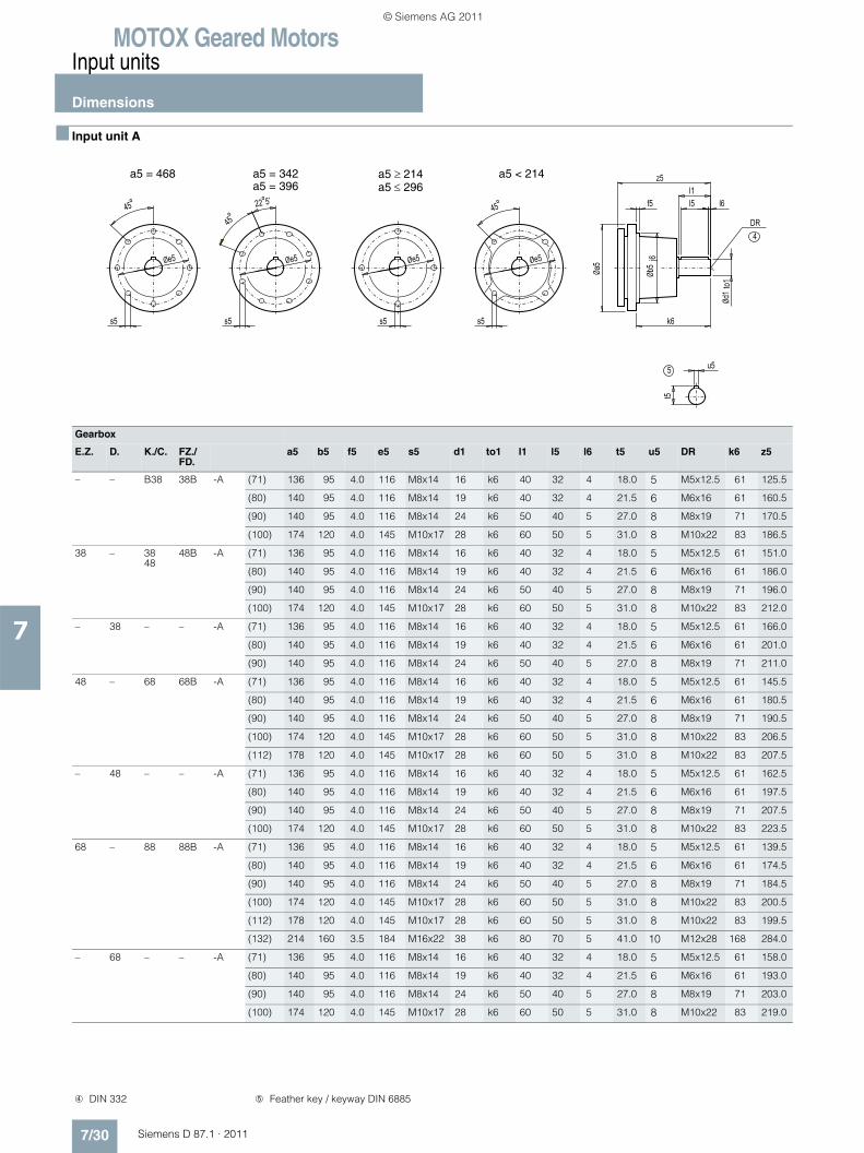
MOTOX Geared MotorsInput units
Dimensions
7/30 Siemens D 87.1 · 2011
7
■ Input unit A
Gearbox
E.Z. D. K./C. FZ./FD.
a5 b5 f5 e5 s5 d1 to1 l1 l5 l6 t5 u5 DR k6 z5
– – B38 38B -A (71) 136 95 4.0 116 M8x14 16 k6 40 32 4 18.0 5 M5x12.5 61 125.5
(80) 140 95 4.0 116 M8x14 19 k6 40 32 4 21.5 6 M6x16 61 160.5
(90) 140 95 4.0 116 M8x14 24 k6 50 40 5 27.0 8 M8x19 71 170.5
(100) 174 120 4.0 145 M10x17 28 k6 60 50 5 31.0 8 M10x22 83 186.5
38 – 3848
48B -A (71) 136 95 4.0 116 M8x14 16 k6 40 32 4 18.0 5 M5x12.5 61 151.0
(80) 140 95 4.0 116 M8x14 19 k6 40 32 4 21.5 6 M6x16 61 186.0
(90) 140 95 4.0 116 M8x14 24 k6 50 40 5 27.0 8 M8x19 71 196.0
(100) 174 120 4.0 145 M10x17 28 k6 60 50 5 31.0 8 M10x22 83 212.0
– 38 – – -A (71) 136 95 4.0 116 M8x14 16 k6 40 32 4 18.0 5 M5x12.5 61 166.0
(80) 140 95 4.0 116 M8x14 19 k6 40 32 4 21.5 6 M6x16 61 201.0
(90) 140 95 4.0 116 M8x14 24 k6 50 40 5 27.0 8 M8x19 71 211.0
48 – 68 68B -A (71) 136 95 4.0 116 M8x14 16 k6 40 32 4 18.0 5 M5x12.5 61 145.5
(80) 140 95 4.0 116 M8x14 19 k6 40 32 4 21.5 6 M6x16 61 180.5
(90) 140 95 4.0 116 M8x14 24 k6 50 40 5 27.0 8 M8x19 71 190.5
(100) 174 120 4.0 145 M10x17 28 k6 60 50 5 31.0 8 M10x22 83 206.5
(112) 178 120 4.0 145 M10x17 28 k6 60 50 5 31.0 8 M10x22 83 207.5
– 48 – – -A (71) 136 95 4.0 116 M8x14 16 k6 40 32 4 18.0 5 M5x12.5 61 162.5
(80) 140 95 4.0 116 M8x14 19 k6 40 32 4 21.5 6 M6x16 61 197.5
(90) 140 95 4.0 116 M8x14 24 k6 50 40 5 27.0 8 M8x19 71 207.5
(100) 174 120 4.0 145 M10x17 28 k6 60 50 5 31.0 8 M10x22 83 223.5
68 – 88 88B -A (71) 136 95 4.0 116 M8x14 16 k6 40 32 4 18.0 5 M5x12.5 61 139.5
(80) 140 95 4.0 116 M8x14 19 k6 40 32 4 21.5 6 M6x16 61 174.5
(90) 140 95 4.0 116 M8x14 24 k6 50 40 5 27.0 8 M8x19 71 184.5
(100) 174 120 4.0 145 M10x17 28 k6 60 50 5 31.0 8 M10x22 83 200.5
(112) 178 120 4.0 145 M10x17 28 k6 60 50 5 31.0 8 M10x22 83 199.5
(132) 214 160 3.5 184 M16x22 38 k6 80 70 5 41.0 10 M12x28 168 284.0
– 68 – – -A (71) 136 95 4.0 116 M8x14 16 k6 40 32 4 18.0 5 M5x12.5 61 158.0
(80) 140 95 4.0 116 M8x14 19 k6 40 32 4 21.5 6 M6x16 61 193.0
(90) 140 95 4.0 116 M8x14 24 k6 50 40 5 27.0 8 M8x19 71 203.0
(100) 174 120 4.0 145 M10x17 28 k6 60 50 5 31.0 8 M10x22 83 219.0
4DR
5
22°5’
45°45° 45°
s5
Øe5
u5
t5
z5
f5
Øa5
Ød1
to1
Øb5
j6
k6
l1l5 l6
s5 s5s5
Øe5 Øe5Øe5
a5 = 468 a5 = 342a5 = 396
a5 ≥ 214a5 ≤ 296
a5 < 214
➃ DIN 332 ➄ Feather key / keyway DIN 6885
© Siemens AG 2011
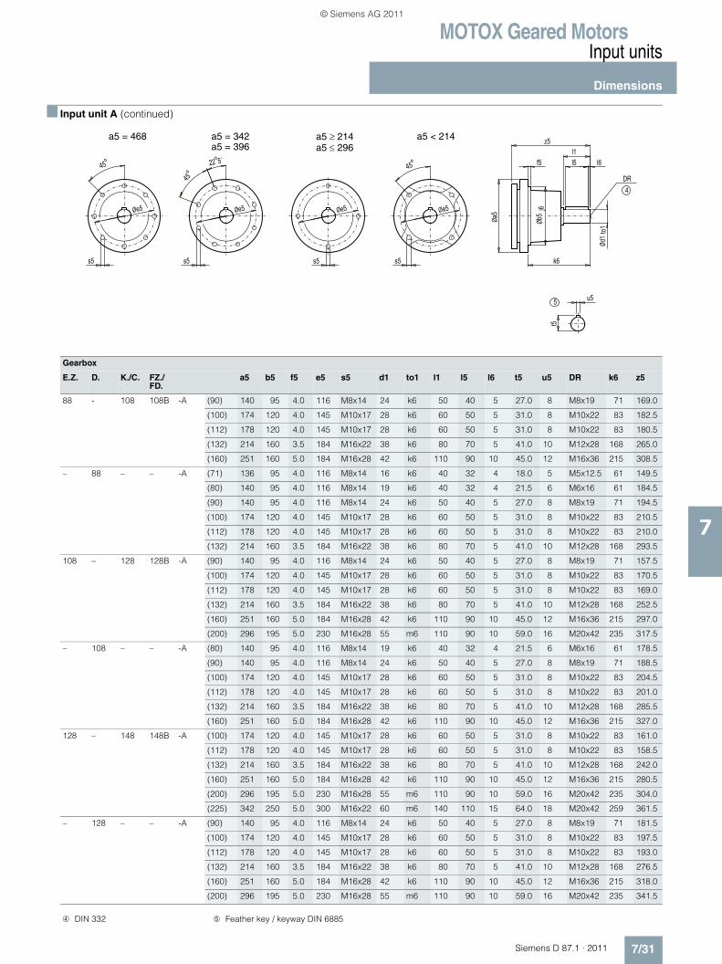
MOTOX Geared MotorsInput units
Dimensions
7/31Siemens D 87.1 · 2011
7
■ Input unit A (continued)
Gearbox
E.Z. D. K./C. FZ./FD.
a5 b5 f5 e5 s5 d1 to1 l1 l5 l6 t5 u5 DR k6 z5
88 - 108 108B -A (90) 140 95 4.0 116 M8x14 24 k6 50 40 5 27.0 8 M8x19 71 169.0
(100) 174 120 4.0 145 M10x17 28 k6 60 50 5 31.0 8 M10x22 83 182.5
(112) 178 120 4.0 145 M10x17 28 k6 60 50 5 31.0 8 M10x22 83 180.5
(132) 214 160 3.5 184 M16x22 38 k6 80 70 5 41.0 10 M12x28 168 265.0
(160) 251 160 5.0 184 M16x28 42 k6 110 90 10 45.0 12 M16x36 215 308.5
– 88 – – -A (71) 136 95 4.0 116 M8x14 16 k6 40 32 4 18.0 5 M5x12.5 61 149.5
(80) 140 95 4.0 116 M8x14 19 k6 40 32 4 21.5 6 M6x16 61 184.5
(90) 140 95 4.0 116 M8x14 24 k6 50 40 5 27.0 8 M8x19 71 194.5
(100) 174 120 4.0 145 M10x17 28 k6 60 50 5 31.0 8 M10x22 83 210.5
(112) 178 120 4.0 145 M10x17 28 k6 60 50 5 31.0 8 M10x22 83 210.0
(132) 214 160 3.5 184 M16x22 38 k6 80 70 5 41.0 10 M12x28 168 293.5
108 – 128 128B -A (90) 140 95 4.0 116 M8x14 24 k6 50 40 5 27.0 8 M8x19 71 157.5
(100) 174 120 4.0 145 M10x17 28 k6 60 50 5 31.0 8 M10x22 83 170.5
(112) 178 120 4.0 145 M10x17 28 k6 60 50 5 31.0 8 M10x22 83 169.0
(132) 214 160 3.5 184 M16x22 38 k6 80 70 5 41.0 10 M12x28 168 252.5
(160) 251 160 5.0 184 M16x28 42 k6 110 90 10 45.0 12 M16x36 215 297.0
(200) 296 195 5.0 230 M16x28 55 m6 110 90 10 59.0 16 M20x42 235 317.5
– 108 – – -A (80) 140 95 4.0 116 M8x14 19 k6 40 32 4 21.5 6 M6x16 61 178.5
(90) 140 95 4.0 116 M8x14 24 k6 50 40 5 27.0 8 M8x19 71 188.5
(100) 174 120 4.0 145 M10x17 28 k6 60 50 5 31.0 8 M10x22 83 204.5
(112) 178 120 4.0 145 M10x17 28 k6 60 50 5 31.0 8 M10x22 83 201.0
(132) 214 160 3.5 184 M16x22 38 k6 80 70 5 41.0 10 M12x28 168 285.5
(160) 251 160 5.0 184 M16x28 42 k6 110 90 10 45.0 12 M16x36 215 327.0
128 – 148 148B -A (100) 174 120 4.0 145 M10x17 28 k6 60 50 5 31.0 8 M10x22 83 161.0
(112) 178 120 4.0 145 M10x17 28 k6 60 50 5 31.0 8 M10x22 83 158.5
(132) 214 160 3.5 184 M16x22 38 k6 80 70 5 41.0 10 M12x28 168 242.0
(160) 251 160 5.0 184 M16x28 42 k6 110 90 10 45.0 12 M16x36 215 280.5
(200) 296 195 5.0 230 M16x28 55 m6 110 90 10 59.0 16 M20x42 235 304.0
(225) 342 250 5.0 300 M16x22 60 m6 140 110 15 64.0 18 M20x42 259 361.5
– 128 – – -A (90) 140 95 4.0 116 M8x14 24 k6 50 40 5 27.0 8 M8x19 71 181.5
(100) 174 120 4.0 145 M10x17 28 k6 60 50 5 31.0 8 M10x22 83 197.5
(112) 178 120 4.0 145 M10x17 28 k6 60 50 5 31.0 8 M10x22 83 193.0
(132) 214 160 3.5 184 M16x22 38 k6 80 70 5 41.0 10 M12x28 168 276.5
(160) 251 160 5.0 184 M16x28 42 k6 110 90 10 45.0 12 M16x36 215 318.0
(200) 296 195 5.0 230 M16x28 55 m6 110 90 10 59.0 16 M20x42 235 341.5
4DR
5
22°5’
45°45° 45°
s5
Øe5
u5
t5
z5
f5
Øa5
Ød1
to1
Øb5
j6
k6
l1l5 l6
s5 s5s5
Øe5 Øe5Øe5
a5 = 468 a5 = 342a5 = 396
a5 ≥ 214a5 ≤ 296
a5 < 214
➃ DIN 332 ➄ Feather key / keyway DIN 6885
© Siemens AG 2011
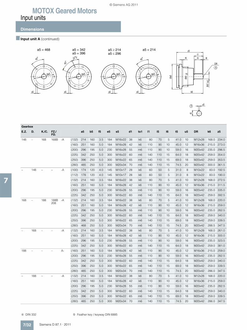
MOTOX Geared MotorsInput units
Dimensions
7/32 Siemens D 87.1 · 2011
7
■ Input unit A (continued)
Gearbox
E.Z. D. K./C. FZ./FD.
a5 b5 f5 e5 s5 d1 to1 l1 l5 l6 t5 u5 DR k6 z5
148 – 168 168B -A (132) 214 160 3.5 184 M16x22 38 k6 80 70 5 41.0 10 M12x28 168.0 234.0
(160) 251 160 5.0 184 M16x28 42 k6 110 90 10 45.0 12 M16x36 215.0 273.0
(200) 296 195 5.0 230 M16x28 55 m6 110 90 10 59.0 16 M20x42 235.0 296.5
(225) 342 250 5.0 300 M16x22 60 m6 140 110 15 64.0 18 M20x42 259.0 354.0
(250) 396 250 5.0 300 M16x22 65 m6 140 110 15 69.0 18 M20x42 259.0 353.5
(280) 485 250 5.0 300 M20x34 70 m6 140 110 15 74.5 20 M20x42 300.0 361.5
– 148 – – -A (100) 174 120 4.0 145 M10x17 28 k6 60 50 5 31.0 8 M10x22 83.0 192.5
(112) 178 120 4.0 145 M10x17 28 k6 60 50 5 31.0 8 M10x22 83.0 190.0
(132) 214 160 3.5 184 M16x22 38 k6 80 70 5 41.0 10 M12x28 168.0 272.5
(160) 251 160 5.0 184 M16x28 42 k6 110 90 10 45.0 12 M16x36 215.0 311.5
(200) 296 195 5.0 230 M16x28 55 m6 110 90 10 59.0 16 M20x42 235.0 335.0
(225) 342 250 5.0 300 M16x22 60 m6 140 110 15 64.0 18 M20x42 259.0 392.5
168 – 188 188B208
-A (132) 214 160 3.5 184 M16x22 38 k6 80 70 5 41.0 10 M12x28 168.0 220.0
(160) 251 160 5.0 184 M16x28 42 k6 110 90 10 45.0 12 M16x36 215.0 259.0
(200) 296 195 5.0 230 M16x28 55 m6 110 90 10 59.0 16 M20x42 235.0 282.5
(225) 342 250 5.0 300 M16x22 60 m6 140 110 15 64.0 18 M20x42 259.0 340.0
(250) 396 250 5.0 300 M16x22 65 m6 140 110 15 69.0 18 M20x42 259.0 339.5
(280) 468 250 5.0 300 M20x34 70 m6 140 110 15 74.5 20 M20x42 288.5 347.5
– 168 – – -A (132) 214 160 3.5 184 M16x22 38 k6 80 70 5 41.0 10 M12x28 168.0 261.0
(160) 251 160 5.0 184 M16x28 42 k6 110 90 10 45.0 12 M16x36 215.0 300.0
(200) 296 195 5.0 230 M16x28 55 m6 110 90 10 59.0 16 M20x42 235.0 323.5
(225) 342 250 5.0 300 M16x22 60 m6 140 110 15 64.0 18 M20x42 259.0 381.0
188 – – – A- (160) 251 160 5.0 184 M16x28 42 k6 110 90 10 45.0 12 M16x36 215.0 259.0
(200) 296 195 5.0 230 M16x28 55 m6 110 90 10 59.0 16 M20x42 235.0 282.5
(225) 342 250 5.0 300 M16x22 60 m6 140 110 15 64.0 18 M20x42 259.0 340.0
(250) 396 250 5.0 300 M16x22 65 m6 140 110 15 69.0 18 M20x42 259.0 339.5
(280) 485 250 5.0 300 M20x34 70 m6 140 110 15 74.5 20 M20x42 286.0 347.5
– 188 – – -A (132) 214 160 3.5 184 M16x22 38 k6 80 70 5 41.0 10 M12x28 168.0 220.0
(160) 251 160 5.0 184 M16x28 42 k6 110 90 10 45.0 12 M16x36 215.0 259.0
(200) 296 195 5.0 230 M16x28 55 m6 110 90 10 59.0 16 M20x42 235.0 282.5
(225) 342 250 5.0 300 M16x22 60 m6 140 110 15 64.0 18 M20x42 259.0 340.0
(250) 396 250 5.0 300 M16x22 65 m6 140 110 15 69.0 18 M20x42 259.0 339.5
(280) 485 250 5.0 300 M20x34 70 m6 140 110 15 74.5 20 M20x42 286.0 347.5
4DR
5
22°5’
45°45° 45°
s5
Øe5
u5
t5
z5
f5
Øa5
Ød1
to1
Øb5
j6
k6
l1l5 l6
s5 s5s5
Øe5 Øe5Øe5
a5 = 468 a5 = 342a5 = 396
a5 ≥ 214a5 ≤ 296
a5 < 214
➃ DIN 332 ➄ Feather key / keyway DIN 6885
© Siemens AG 2011
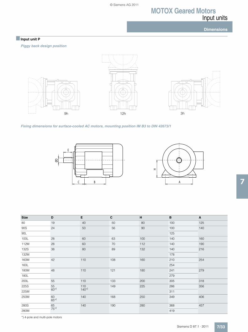
MOTOX Geared MotorsInput units
Dimensions
7/33Siemens D 87.1 · 2011
7
■ Input unit P
Piggy back design position
Fixing dimensions for surface-cooled AC motors, mounting position IM B3 to DIN 42673/1
9h 12h 3h
C
H
AB
ØD
E
Size D E C H B A
80 19 40 50 80 100 125
90S 24 50 56 90 100 140
90L 125
100L 28 60 63 100 140 160
112M 28 60 70 112 140 190
132S 38 80 89 132 140 216
132M 178
160M 42 110 108 160 210 254
160L 254
180M 48 110 121 180 241 279
180L 279
200L 55 110 133 200 305 318
225S 5560*)
110140*)
149 225 286 356
225M 311
250M 6065*)
140 168 250 349 406
280S 6575*)
140 190 280 368 457
280M 419
*) 4-pole and multi-pole motors
© Siemens AG 2011

MOTOX Geared MotorsInput units
Dimensions
7/34 Siemens D 87.1 · 2011
7
■ Input unit P (continued)
Gearbox 12h 3/9h
a5 e f i9 h0 h1 h1 h0 h1 h1 d1 to1 l1 l5 l6 t5 u5 DR i8 z5
Max. Min. Max. Max. Min. Max.
F.38B -P (80) 140 225 174 44 88 130 225 88 130 225 19 k6 40 32 4 21.5 6 M6x16 53 160.5
(90) 140 225 174 53 88 130 225 88 130 225 24 k6 50 40 5 27.0 8 M8x19 63 170.5
(100) 174 250 232 60 88 145 240 88 145 240 28 k6 60 50 5 31.0 8 M10x22 73 186.5
E./Z.38K.38/48C.38/48
-P (80) 140 225 174 44 88 130 235 88 130 235 19 k6 40 32 4 21.5 6 M6x16 53 185.5
(90) 140 225 174 53 88 130 235 88 130 235 24 k6 50 40 5 27.0 8 M8x19 63 195.5
(100) 174 250 232 60 88 145 240 88 145 240 28 k6 60 50 5 31.0 8 M10x22 73 211.5
D.38 -P (80) 140 225 174 44 88 130 235 88 130 235 19 k6 40 32 4 21.5 6 M6x16 53 200.5
(90) 140 225 174 53 88 130 235 88 130 235 24 k6 50 40 5 27.0 8 M8x19 63 210.0
E./Z.48 -P (80) 140 225 174 44 88 130 235 88 140 235 19 k6 40 32 4 21.5 6 M6x16 53 180.0
(90) 140 225 174 53 88 130 235 88 140 235 24 k6 50 40 5 27.0 8 M8x19 63 190.0
(100) 174 250 232 60 88 145 240 88 145 240 28 k6 60 50 5 31.0 8 M10x22 73 206.0
(112) 178 250 232 67 88 145 240 88 145 240 28 k6 60 50 5 31.0 8 M10x22 73 207.0
D.48 -P (80) 140 225 174 44 88 130 235 88 140 235 19 k6 40 32 4 21.5 6 M6x16 53 197.0
(90) 140 225 174 53 88 130 235 88 140 235 24 k6 50 40 5 27.0 8 M8x19 63 207.0
(100) 174 250 232 60 88 145 240 88 145 240 28 k6 60 50 5 31.0 8 M10x22 73 223.0
F.48B -P (80) 140 225 174 44 88 130 225 88 130 225 19 k6 40 32 4 21.5 6 M6x16 53 186.0
(90) 140 225 174 53 88 130 225 88 130 225 24 k6 50 40 5 27.0 8 M8x19 63 196.0
(100) 174 250 232 60 88 145 240 88 145 240 28 k6 60 50 5 31.0 8 M10x22 73 212.0
(112) 178 250 232 67 88 145 240 88 145 240 28 k6 60 50 5 31.0 8 M10x22 73 181.0
E.68 -P (80) 140 225 174 44 88 140 235 88 130 235 19 k6 40 32 4 21.5 6 M6x16 53 174.0
(90) 140 225 174 53 88 140 235 88 130 235 24 k6 50 40 5 27.0 8 M8x19 63 184.0
(100) 174 250 232 60 88 150 240 88 150 240 28 k6 60 50 5 31.0 8 M10x22 73 200.0
(112) 178 250 232 67 88 150 240 88 150 240 28 k6 60 50 5 31.0 8 M10x22 73 199.0
(132) 214 374 300 84 209 180 270 184 180 270 38 k6 80 70 5 41.0 10 M12x28 85 283.5
D.68 -P (80) 140 225 174 44 88 140 235 88 160 235 19 k6 40 32 4 21.5 6 M6x16 53 192.5
(90) 140 225 174 53 88 140 235 88 160 235 24 k6 50 40 5 27.0 8 M8x19 63 202.5
(100) 174 250 232 60 88 145 240 88 160 240 28 k6 60 50 5 31.0 8 M10x22 73 218.5
Z.68 -P (80) 140 225 174 44 88 140 235 88 160 235 19 k6 40 32 4 21.5 6 M6x16 53 174.0
(90) 140 225 174 53 88 140 235 88 160 235 24 k6 50 40 5 27.0 8 M8x19 63 184.0
(100) 174 250 232 60 88 145 240 88 160 240 28 k6 60 50 5 31.0 8 M10x22 73 200.0
(112) 178 250 232 67 88 145 240 88 160 240 28 k6 60 50 5 31.0 8 M10x22 73 199.0
(132) 214 374 300 84 139 180 230 139 180 230 38 k6 80 70 5 41.0 10 M12x28 85 283.5
4DR
5
fe
i8
u5
t5
h0h1
Øa5
Ød1
to1
l1l5 l6
i9
z5
➃ DIN 332 ➄ Feather key / keyway DIN 6885
© Siemens AG 2011
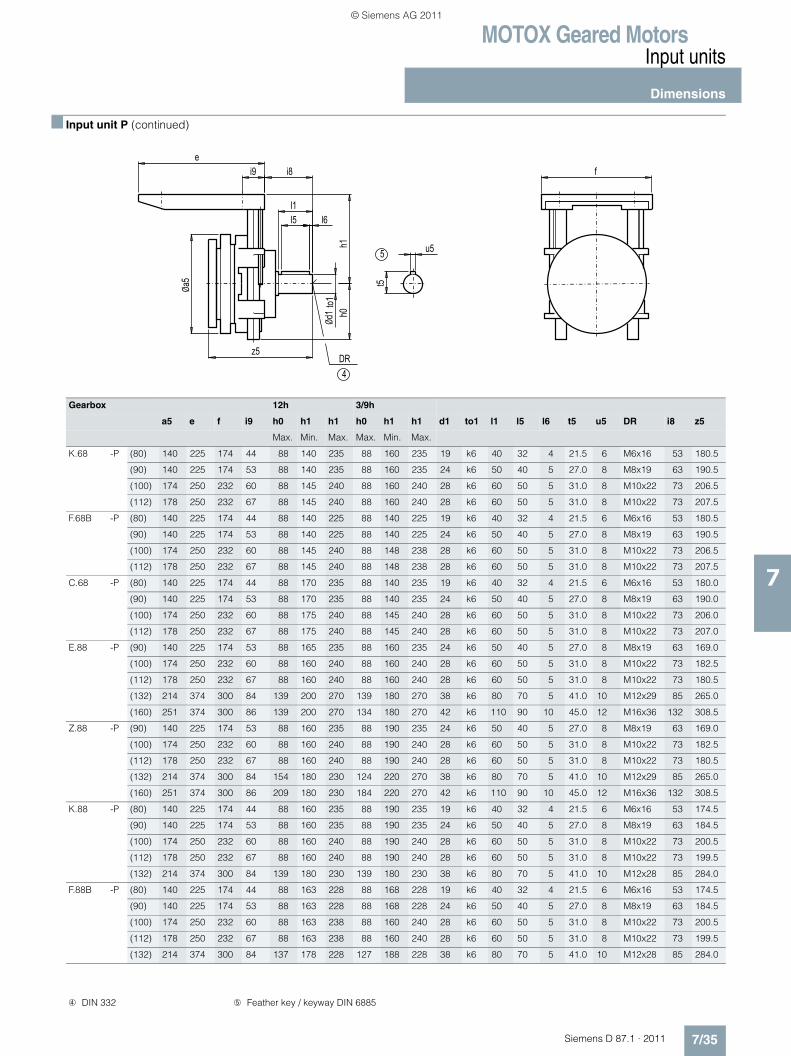
MOTOX Geared MotorsInput units
Dimensions
7/35Siemens D 87.1 · 2011
7
■ Input unit P (continued)
Gearbox 12h 3/9h
a5 e f i9 h0 h1 h1 h0 h1 h1 d1 to1 l1 l5 l6 t5 u5 DR i8 z5
Max. Min. Max. Max. Min. Max.
K.68 -P (80) 140 225 174 44 88 140 235 88 160 235 19 k6 40 32 4 21.5 6 M6x16 53 180.5
(90) 140 225 174 53 88 140 235 88 160 235 24 k6 50 40 5 27.0 8 M8x19 63 190.5
(100) 174 250 232 60 88 145 240 88 160 240 28 k6 60 50 5 31.0 8 M10x22 73 206.5
(112) 178 250 232 67 88 145 240 88 160 240 28 k6 60 50 5 31.0 8 M10x22 73 207.5
F.68B -P (80) 140 225 174 44 88 140 225 88 140 225 19 k6 40 32 4 21.5 6 M6x16 53 180.5
(90) 140 225 174 53 88 140 225 88 140 225 24 k6 50 40 5 27.0 8 M8x19 63 190.5
(100) 174 250 232 60 88 145 240 88 148 238 28 k6 60 50 5 31.0 8 M10x22 73 206.5
(112) 178 250 232 67 88 145 240 88 148 238 28 k6 60 50 5 31.0 8 M10x22 73 207.5
C.68 -P (80) 140 225 174 44 88 170 235 88 140 235 19 k6 40 32 4 21.5 6 M6x16 53 180.0
(90) 140 225 174 53 88 170 235 88 140 235 24 k6 50 40 5 27.0 8 M8x19 63 190.0
(100) 174 250 232 60 88 175 240 88 145 240 28 k6 60 50 5 31.0 8 M10x22 73 206.0
(112) 178 250 232 67 88 175 240 88 145 240 28 k6 60 50 5 31.0 8 M10x22 73 207.0
E.88 -P (90) 140 225 174 53 88 165 235 88 160 235 24 k6 50 40 5 27.0 8 M8x19 63 169.0
(100) 174 250 232 60 88 160 240 88 160 240 28 k6 60 50 5 31.0 8 M10x22 73 182.5
(112) 178 250 232 67 88 160 240 88 160 240 28 k6 60 50 5 31.0 8 M10x22 73 180.5
(132) 214 374 300 84 139 200 270 139 180 270 38 k6 80 70 5 41.0 10 M12x29 85 265.0
(160) 251 374 300 86 139 200 270 134 180 270 42 k6 110 90 10 45.0 12 M16x36 132 308.5
Z.88 -P (90) 140 225 174 53 88 160 235 88 190 235 24 k6 50 40 5 27.0 8 M8x19 63 169.0
(100) 174 250 232 60 88 160 240 88 190 240 28 k6 60 50 5 31.0 8 M10x22 73 182.5
(112) 178 250 232 67 88 160 240 88 190 240 28 k6 60 50 5 31.0 8 M10x22 73 180.5
(132) 214 374 300 84 154 180 230 124 220 270 38 k6 80 70 5 41.0 10 M12x29 85 265.0
(160) 251 374 300 86 209 180 230 184 220 270 42 k6 110 90 10 45.0 12 M16x36 132 308.5
K.88 -P (80) 140 225 174 44 88 160 235 88 190 235 19 k6 40 32 4 21.5 6 M6x16 53 174.5
(90) 140 225 174 53 88 160 235 88 190 235 24 k6 50 40 5 27.0 8 M8x19 63 184.5
(100) 174 250 232 60 88 160 240 88 190 240 28 k6 60 50 5 31.0 8 M10x22 73 200.5
(112) 178 250 232 67 88 160 240 88 190 240 28 k6 60 50 5 31.0 8 M10x22 73 199.5
(132) 214 374 300 84 139 180 230 139 180 230 38 k6 80 70 5 41.0 10 M12x28 85 284.0
F.88B -P (80) 140 225 174 44 88 163 228 88 168 228 19 k6 40 32 4 21.5 6 M6x16 53 174.5
(90) 140 225 174 53 88 163 228 88 168 228 24 k6 50 40 5 27.0 8 M8x19 63 184.5
(100) 174 250 232 60 88 163 238 88 160 240 28 k6 60 50 5 31.0 8 M10x22 73 200.5
(112) 178 250 232 67 88 163 238 88 160 240 28 k6 60 50 5 31.0 8 M10x22 73 199.5
(132) 214 374 300 84 137 178 228 127 188 228 38 k6 80 70 5 41.0 10 M12x28 85 284.0
4DR
5
fe
i8
u5
t5
h0h1
Øa5
Ød1
to1
l1l5 l6
i9
z5
➃ DIN 332 ➄ Feather key / keyway DIN 6885
© Siemens AG 2011
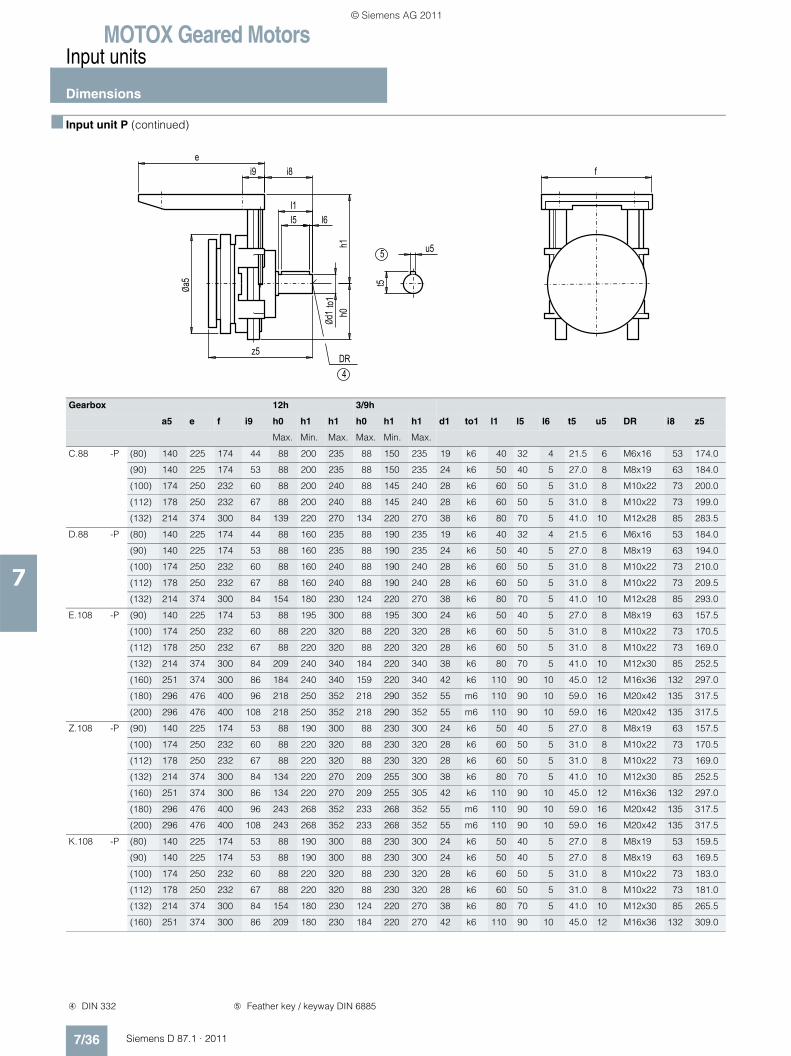
MOTOX Geared MotorsInput units
Dimensions
7/36 Siemens D 87.1 · 2011
7
■ Input unit P (continued)
Gearbox 12h 3/9h
a5 e f i9 h0 h1 h1 h0 h1 h1 d1 to1 l1 l5 l6 t5 u5 DR i8 z5
Max. Min. Max. Max. Min. Max.
C.88 -P (80) 140 225 174 44 88 200 235 88 150 235 19 k6 40 32 4 21.5 6 M6x16 53 174.0
(90) 140 225 174 53 88 200 235 88 150 235 24 k6 50 40 5 27.0 8 M8x19 63 184.0
(100) 174 250 232 60 88 200 240 88 145 240 28 k6 60 50 5 31.0 8 M10x22 73 200.0
(112) 178 250 232 67 88 200 240 88 145 240 28 k6 60 50 5 31.0 8 M10x22 73 199.0
(132) 214 374 300 84 139 220 270 134 220 270 38 k6 80 70 5 41.0 10 M12x28 85 283.5
D.88 -P (80) 140 225 174 44 88 160 235 88 190 235 19 k6 40 32 4 21.5 6 M6x16 53 184.0
(90) 140 225 174 53 88 160 235 88 190 235 24 k6 50 40 5 27.0 8 M8x19 63 194.0
(100) 174 250 232 60 88 160 240 88 190 240 28 k6 60 50 5 31.0 8 M10x22 73 210.0
(112) 178 250 232 67 88 160 240 88 190 240 28 k6 60 50 5 31.0 8 M10x22 73 209.5
(132) 214 374 300 84 154 180 230 124 220 270 38 k6 80 70 5 41.0 10 M12x28 85 293.0
E.108 -P (90) 140 225 174 53 88 195 300 88 195 300 24 k6 50 40 5 27.0 8 M8x19 63 157.5
(100) 174 250 232 60 88 220 320 88 220 320 28 k6 60 50 5 31.0 8 M10x22 73 170.5
(112) 178 250 232 67 88 220 320 88 220 320 28 k6 60 50 5 31.0 8 M10x22 73 169.0
(132) 214 374 300 84 209 240 340 184 220 340 38 k6 80 70 5 41.0 10 M12x30 85 252.5
(160) 251 374 300 86 184 240 340 159 220 340 42 k6 110 90 10 45.0 12 M16x36 132 297.0
(180) 296 476 400 96 218 250 352 218 290 352 55 m6 110 90 10 59.0 16 M20x42 135 317.5
(200) 296 476 400 108 218 250 352 218 290 352 55 m6 110 90 10 59.0 16 M20x42 135 317.5
Z.108 -P (90) 140 225 174 53 88 190 300 88 230 300 24 k6 50 40 5 27.0 8 M8x19 63 157.5
(100) 174 250 232 60 88 220 320 88 230 320 28 k6 60 50 5 31.0 8 M10x22 73 170.5
(112) 178 250 232 67 88 220 320 88 230 320 28 k6 60 50 5 31.0 8 M10x22 73 169.0
(132) 214 374 300 84 134 220 270 209 255 300 38 k6 80 70 5 41.0 10 M12x30 85 252.5
(160) 251 374 300 86 134 220 270 209 255 305 42 k6 110 90 10 45.0 12 M16x36 132 297.0
(180) 296 476 400 96 243 268 352 233 268 352 55 m6 110 90 10 59.0 16 M20x42 135 317.5
(200) 296 476 400 108 243 268 352 233 268 352 55 m6 110 90 10 59.0 16 M20x42 135 317.5
K.108 -P (80) 140 225 174 53 88 190 300 88 230 300 24 k6 50 40 5 27.0 8 M8x19 53 159.5
(90) 140 225 174 53 88 190 300 88 230 300 24 k6 50 40 5 27.0 8 M8x19 63 169.5
(100) 174 250 232 60 88 220 320 88 230 320 28 k6 60 50 5 31.0 8 M10x22 73 183.0
(112) 178 250 232 67 88 220 320 88 230 320 28 k6 60 50 5 31.0 8 M10x22 73 181.0
(132) 214 374 300 84 154 180 230 124 220 270 38 k6 80 70 5 41.0 10 M12x30 85 265.5
(160) 251 374 300 86 209 180 230 184 220 270 42 k6 110 90 10 45.0 12 M16x36 132 309.0
4DR
5
fe
i8
u5
t5
h0h1
Øa5
Ød1
to1
l1l5 l6
i9
z5
➃ DIN 332 ➄ Feather key / keyway DIN 6885
© Siemens AG 2011
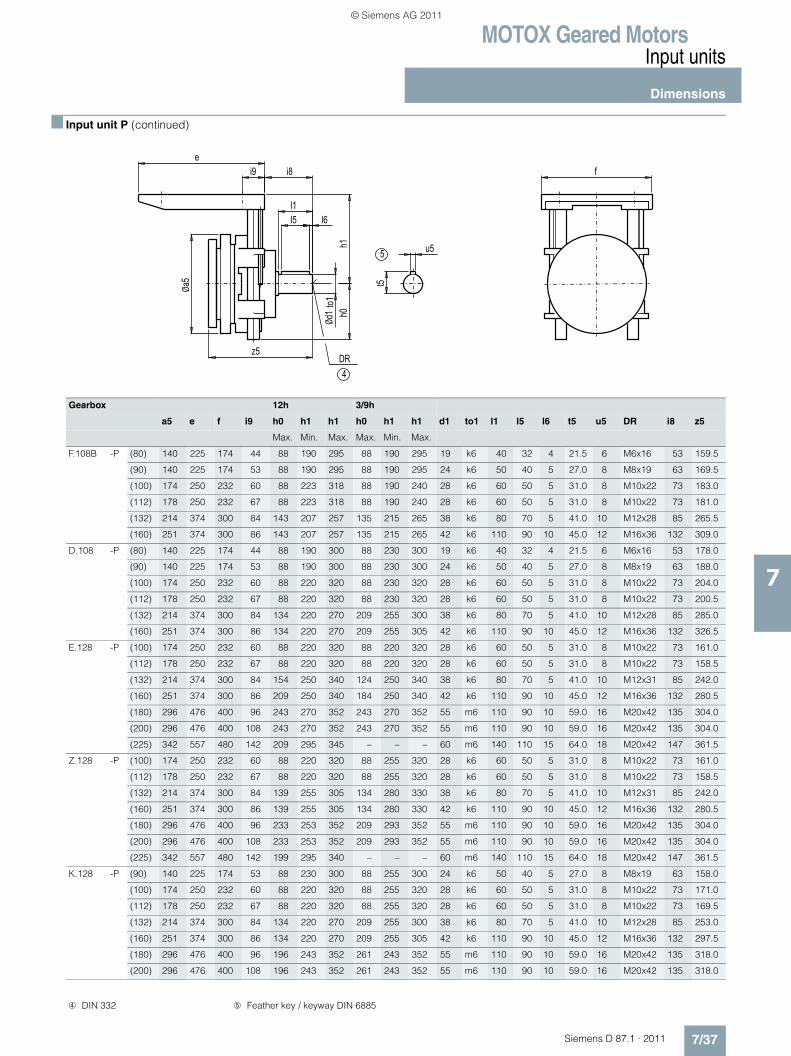
MOTOX Geared MotorsInput units
Dimensions
7/37Siemens D 87.1 · 2011
7
■ Input unit P (continued)
Gearbox 12h 3/9h
a5 e f i9 h0 h1 h1 h0 h1 h1 d1 to1 l1 l5 l6 t5 u5 DR i8 z5
Max. Min. Max. Max. Min. Max.
F.108B -P (80) 140 225 174 44 88 190 295 88 190 295 19 k6 40 32 4 21.5 6 M6x16 53 159.5
(90) 140 225 174 53 88 190 295 88 190 295 24 k6 50 40 5 27.0 8 M8x19 63 169.5
(100) 174 250 232 60 88 223 318 88 190 240 28 k6 60 50 5 31.0 8 M10x22 73 183.0
(112) 178 250 232 67 88 223 318 88 190 240 28 k6 60 50 5 31.0 8 M10x22 73 181.0
(132) 214 374 300 84 143 207 257 135 215 265 38 k6 80 70 5 41.0 10 M12x28 85 265.5
(160) 251 374 300 86 143 207 257 135 215 265 42 k6 110 90 10 45.0 12 M16x36 132 309.0
D.108 -P (80) 140 225 174 44 88 190 300 88 230 300 19 k6 40 32 4 21.5 6 M6x16 53 178.0
(90) 140 225 174 53 88 190 300 88 230 300 24 k6 50 40 5 27.0 8 M8x19 63 188.0
(100) 174 250 232 60 88 220 320 88 230 320 28 k6 60 50 5 31.0 8 M10x22 73 204.0
(112) 178 250 232 67 88 220 320 88 230 320 28 k6 60 50 5 31.0 8 M10x22 73 200.5
(132) 214 374 300 84 134 220 270 209 255 300 38 k6 80 70 5 41.0 10 M12x28 85 285.0
(160) 251 374 300 86 134 220 270 209 255 305 42 k6 110 90 10 45.0 12 M16x36 132 326.5
E.128 -P (100) 174 250 232 60 88 220 320 88 220 320 28 k6 60 50 5 31.0 8 M10x22 73 161.0
(112) 178 250 232 67 88 220 320 88 220 320 28 k6 60 50 5 31.0 8 M10x22 73 158.5
(132) 214 374 300 84 154 250 340 124 250 340 38 k6 80 70 5 41.0 10 M12x31 85 242.0
(160) 251 374 300 86 209 250 340 184 250 340 42 k6 110 90 10 45.0 12 M16x36 132 280.5
(180) 296 476 400 96 243 270 352 243 270 352 55 m6 110 90 10 59.0 16 M20x42 135 304.0
(200) 296 476 400 108 243 270 352 243 270 352 55 m6 110 90 10 59.0 16 M20x42 135 304.0
(225) 342 557 480 142 209 295 345 – – – 60 m6 140 110 15 64.0 18 M20x42 147 361.5
Z.128 -P (100) 174 250 232 60 88 220 320 88 255 320 28 k6 60 50 5 31.0 8 M10x22 73 161.0
(112) 178 250 232 67 88 220 320 88 255 320 28 k6 60 50 5 31.0 8 M10x22 73 158.5
(132) 214 374 300 84 139 255 305 134 280 330 38 k6 80 70 5 41.0 10 M12x31 85 242.0
(160) 251 374 300 86 139 255 305 134 280 330 42 k6 110 90 10 45.0 12 M16x36 132 280.5
(180) 296 476 400 96 233 253 352 209 293 352 55 m6 110 90 10 59.0 16 M20x42 135 304.0
(200) 296 476 400 108 233 253 352 209 293 352 55 m6 110 90 10 59.0 16 M20x42 135 304.0
(225) 342 557 480 142 199 295 340 – – – 60 m6 140 110 15 64.0 18 M20x42 147 361.5
K.128 -P (90) 140 225 174 53 88 230 300 88 255 300 24 k6 50 40 5 27.0 8 M8x19 63 158.0
(100) 174 250 232 60 88 220 320 88 255 320 28 k6 60 50 5 31.0 8 M10x22 73 171.0
(112) 178 250 232 67 88 220 320 88 255 320 28 k6 60 50 5 31.0 8 M10x22 73 169.5
(132) 214 374 300 84 134 220 270 209 255 300 38 k6 80 70 5 41.0 10 M12x28 85 253.0
(160) 251 374 300 86 134 220 270 209 255 305 42 k6 110 90 10 45.0 12 M16x36 132 297.5
(180) 296 476 400 96 196 243 352 261 243 352 55 m6 110 90 10 59.0 16 M20x42 135 318.0
(200) 296 476 400 108 196 243 352 261 243 352 55 m6 110 90 10 59.0 16 M20x42 135 318.0
4DR
5
fe
i8
u5
t5
h0h1
Øa5
Ød1
to1
l1l5 l6
i9
z5
➃ DIN 332 ➄ Feather key / keyway DIN 6885
© Siemens AG 2011

MOTOX Geared MotorsInput units
Dimensions
7/38 Siemens D 87.1 · 2011
7
■ Input unit P (continued)
Gearbox 12h 3/9h
a5 e f i9 h0 h1 h1 h0 h1 h1 d1 to1 l1 l5 l6 t5 u5 DR i8 z5
Max. Min. Max. Max. Min. Max.
F.128B -P (90) 140 225 174 53 88 235 295 88 230 295 24 k6 50 40 5 27.0 8 M8x19 63 158.0
(100) 174 250 232 60 88 250 320 88 235 320 28 k6 60 50 5 31.0 8 M10x22 73 171.0
(112) 178 250 232 67 88 250 320 88 235 320 28 k6 60 50 5 31.0 8 M10x22 73 169.5
(132) 214 374 300 84 195 265 365 175 285 365 38 k6 80 70 5 41.0 10 M12x28 85 253.0
(160) 251 374 300 86 195 265 365 175 285 365 42 k6 110 90 10 45.0 12 M16x36 132 297.5
(180) 296 476 400 96 217 268 358 217 268 358 55 m6 110 90 10 59.0 16 M20x42 135 318.0
(200) 296 476 400 108 217 268 358 217 268 358 55 m6 110 90 10 59.0 16 M20x42 135 318.0
D.128 -P (90) 140 225 174 53 88 230 300 88 255 300 24 k6 50 40 5 27.0 8 M8x19 63 181.0
(100) 174 250 232 60 88 220 320 88 255 320 28 k6 60 50 5 31.0 8 M10x22 73 197.0
(112) 178 250 232 67 88 220 320 88 255 320 28 k6 60 50 5 31.0 8 M10x22 73 192.5
(132) 214 374 300 84 139 255 305 134 280 330 38 k6 80 70 5 41.0 10 M12x28 85 276.0
(160) 251 374 300 86 139 255 305 134 280 330 42 k6 110 90 10 45.0 12 M16x36 132 317.5
(180) 296 476 400 96 233 253 352 209 293 352 55 m6 110 90 10 59.0 16 M20x42 135 341.0
(200) 296 476 400 108 233 253 352 209 293 352 55 m6 110 90 10 59.0 16 M20x42 135 341.0
E.148 -P (132) 214 374 300 84 134 280 380 209 280 380 38 k6 80 70 5 41.0 10 M12x32 85 234.0
(160) 251 374 300 86 134 280 380 209 280 380 42 k6 110 90 10 45.0 12 M16x36 132 273.0
(180) 296 476 400 96 193 300 425 233 300 425 55 m6 110 90 10 59.0 16 M20x42 135 296.5
(200) 296 476 400 108 193 300 425 233 300 425 55 m6 110 90 10 59.0 16 M20x42 135 296.5
(225) 342 557 480 142 254 315 415 – – – 60 m6 140 110 15 64.0 18 M20x42 147 354.0
(250) 396 557 480 161 254 305 350 – – – 65 m6 140 110 15 69.0 18 M20x42 147 353.5
(280) 485 666 558 173 265 399 369 – – – 70 m6 140 110 15 74.5 20 M20x42 171 361.5
D.148 -P (100) 174 250 232 60 88 245 320 88 280 320 28 k6 60 50 5 31.0 8 M10x22 73 192.0
(112) 178 250 232 67 88 245 320 88 280 320 28 k6 60 50 5 31.0 8 M10x22 73 189.5
(132) 214 374 300 84 184 280 330 159 305 355 38 k6 80 70 5 41.0 10 M12x28 85 272.0
(160) 251 374 300 86 184 280 330 159 305 355 42 k6 110 90 10 45.0 12 M16x36 132 311.0
(180) 296 476 400 96 248 318 407 248 318 407 55 m6 110 90 10 59.0 16 M20x42 135 334.5
(200) 296 476 400 108 248 293 352 248 318 407 55 m6 110 90 10 59.0 16 M20x42 135 334.5
(225) 342 557 480 142 199 305 350 – – – 60 m6 140 110 15 64.0 18 M20x42 147 392.0
Z.148 -P (132) 214 374 300 84 184 280 330 159 305 355 38 k6 80 70 5 41.0 10 M12x28 85 234.0
(160) 251 374 300 86 184 280 330 159 305 355 42 k6 110 90 10 45.0 12 M16x36 132 273.0
(180) 296 476 400 96 248 318 407 248 318 407 55 m6 110 90 10 59.0 16 M20x42 135 296.5
(200) 296 476 400 108 248 293 352 248 318 407 55 m6 110 90 10 59.0 16 M20x42 135 296.5
(225) 342 557 480 142 199 305 350 – – – 60 m6 140 110 15 64.0 18 M20x42 147 354.0
(250) 396 557 480 161 254 305 350 – – – 65 m6 140 110 15 69.0 18 M20x42 147 353.5
(280) 485 666 558 173 265 399 429 – – – 70 m6 140 110 15 74.5 20 M20x42 171 361.5
4DR
5
fe
i8
u5
t5
h0h1
Øa5
Ød1
to1
l1l5 l6
i9
z5
➃ DIN 332 ➄ Feather key / keyway DIN 6885
© Siemens AG 2011
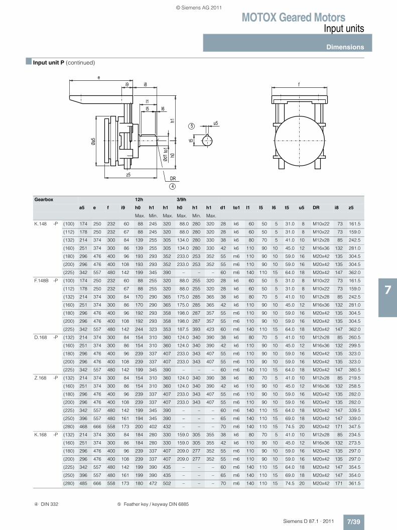
MOTOX Geared MotorsInput units
Dimensions
7/39Siemens D 87.1 · 2011
7
■ Input unit P (continued)
Gearbox 12h 3/9h
a5 e f i9 h0 h1 h1 h0 h1 h1 d1 to1 l1 l5 l6 t5 u5 DR i8 z5
Max. Min. Max. Max. Min. Max.
K.148 -P (100) 174 250 232 60 88 245 320 88.0 280 320 28 k6 60 50 5 31.0 8 M10x22 73 161.5
(112) 178 250 232 67 88 245 320 88.0 280 320 28 k6 60 50 5 31.0 8 M10x22 73 159.0
(132) 214 374 300 84 139 255 305 134.0 280 330 38 k6 80 70 5 41.0 10 M12x28 85 242.5
(160) 251 374 300 86 139 255 305 134.0 280 330 42 k6 110 90 10 45.0 12 M16x36 132 281.0
(180) 296 476 400 96 193 293 352 233.0 253 352 55 m6 110 90 10 59.0 16 M20x42 135 304.5
(200) 296 476 400 108 193 293 352 233.0 253 352 55 m6 110 90 10 59.0 16 M20x42 135 304.5
(225) 342 557 480 142 199 345 390 – – – 60 m6 140 110 15 64.0 18 M20x42 147 362.0
F.148B -P (100) 174 250 232 60 88 255 320 88.0 255 320 28 k6 60 50 5 31.0 8 M10x22 73 161.5
(112) 178 250 232 67 88 255 320 88.0 255 320 28 k6 60 50 5 31.0 8 M10x22 73 159.0
(132) 214 374 300 84 170 290 365 175.0 285 365 38 k6 80 70 5 41.0 10 M12x28 85 242.5
(160) 251 374 300 86 170 290 365 175.0 285 365 42 k6 110 90 10 45.0 12 M16x36 132 281.0
(180) 296 476 400 96 192 293 358 198.0 287 357 55 m6 110 90 10 59.0 16 M20x42 135 304.5
(200) 296 476 400 108 192 293 358 198.0 287 357 55 m6 110 90 10 59.0 16 M20x42 135 304.5
(225) 342 557 480 142 244 323 353 187.5 393 423 60 m6 140 110 15 64.0 18 M20x42 147 362.0
D.168 -P (132) 214 374 300 84 154 310 360 124.0 340 390 38 k6 80 70 5 41.0 10 M12x28 85 260.5
(160) 251 374 300 86 154 310 360 124.0 340 390 42 k6 110 90 10 45.0 12 M16x36 132 299.5
(180) 296 476 400 96 239 337 407 233.0 343 407 55 m6 110 90 10 59.0 16 M20x42 135 323.0
(200) 296 476 400 108 239 337 407 233.0 343 407 55 m6 110 90 10 59.0 16 M20x42 135 323.0
(225) 342 557 480 142 199 345 390 – – – 60 m6 140 110 15 64.0 18 M20x42 147 380.5
Z.168 -P (132) 214 374 300 84 154 310 360 124.0 340 390 38 k6 80 70 5 41.0 10 M12x28 85 219.5
(160) 251 374 300 86 154 310 360 124.0 340 390 42 k6 110 90 10 45.0 12 M16x36 132 258.5
(180) 296 476 400 96 239 337 407 233.0 343 407 55 m6 110 90 10 59.0 16 M20x42 135 282.0
(200) 296 476 400 108 239 337 407 233.0 343 407 55 m6 110 90 10 59.0 16 M20x42 135 282.0
(225) 342 557 480 142 199 345 390 – – – 60 m6 140 110 15 64.0 18 M20x42 147 339.5
(250) 396 557 480 161 194 345 390 – – – 65 m6 140 110 15 69.0 18 M20x42 147 339.0
(280) 468 666 558 173 200 402 432 – – – 70 m6 140 110 15 74.5 20 M20x42 171 347.5
K.168 -P (132) 214 374 300 84 184 280 330 159.0 305 355 38 k6 80 70 5 41.0 10 M12x28 85 234.5
(160) 251 374 300 86 184 280 330 159.0 305 355 42 k6 110 90 10 45.0 12 M16x36 132 273.5
(180) 296 476 400 96 239 337 407 209.0 277 352 55 m6 110 90 10 59.0 16 M20x42 135 297.0
(200) 296 476 400 108 239 337 407 209.0 277 352 55 m6 110 90 10 59.0 16 M20x42 135 297.0
(225) 342 557 480 142 199 390 435 – – – 60 m6 140 110 15 64.0 18 M20x42 147 354.5
(250) 396 557 480 161 199 390 435 – – – 65 m6 140 110 15 69.0 18 M20x42 147 354.0
(280) 485 666 558 173 180 472 502 – – – 70 m6 140 110 15 74.5 20 M20x42 171 361.5
4DR
5
fe
i8
u5
t5
h0h1
Øa5
Ød1
to1
l1l5 l6
i9
z5
➃ DIN 332 ➄ Feather key / keyway DIN 6885
© Siemens AG 2011
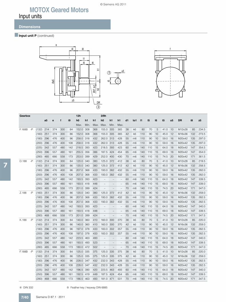
MOTOX Geared MotorsInput units
Dimensions
7/40 Siemens D 87.1 · 2011
7
■ Input unit P (continued)
Gearbox 12h 3/9h
a5 e f i9 h0 h1 h1 h0 h1 h1 d1 to1 l1 l5 l6 t5 u5 DR i8 z5
Max. Min. Max. Max. Min. Max.
F.168B -P (132) 214 374 300 84 152.0 308 368 155.0 305 365 38 k6 80 70 5 41.0 10 M12x28 85 234.5
(160) 251 374 300 86 152.0 308 368 155.0 305 365 42 k6 110 90 10 45.0 12 M16x36 132 273.5
(180) 296 476 400 96 258.0 318 432 262.0 313 428 55 m6 110 90 10 59.0 16 M20x42 135 297.0
(200) 296 476 400 108 258.0 318 432 262.0 313 428 55 m6 110 90 10 59.0 16 M20x42 135 297.0
(225) 342 557 480 142 218.5 393 423 218.5 393 423 60 m6 140 110 15 64.0 18 M20x42 147 354.5
(250) 396 557 480 161 255.5 356 386 187.5 424 454 65 m6 140 110 15 69.0 18 M20x42 147 354.0
(280) 485 666 558 173 253.0 399 429 252.0 400 430 70 m6 140 110 15 74.5 20 M20x42 171 361.5
D.188 -P (132) 214 374 300 84 120.0 340 380 125.0 372 412 38 k6 80 70 5 41.0 10 M12x28 85 219.5
(160) 251 374 300 86 120.0 340 380 125.0 372 412 42 k6 110 90 10 45.0 12 M16x36 132 258.5
(180) 296 476 400 96 207.0 368 433 193.0 382 432 55 m6 110 90 10 59.0 16 M20x42 135 282.0
(200) 296 476 400 108 207.0 368 433 193.0 382 432 55 m6 110 90 10 59.0 16 M20x42 135 282.0
(225) 342 557 480 142 193.5 393 423 – – – 60 m6 140 110 15 64.0 18 M20x42 147 339.5
(250) 396 557 480 161 193.5 418 448 – – – 65 m6 140 110 15 69.0 18 M20x42 147 339.0
(280) 485 666 558 173 201.0 399 424 – – – 70 m6 140 110 15 74.5 20 M20x42 171 347.0
Z.188 -P (160) 251 374 300 86 120.0 340 380 125.0 372 412 42 k6 110 90 10 45.0 12 M16x36 132 259.0
(180) 296 476 400 96 207.0 368 433 193.0 382 432 55 m6 110 90 10 59.0 16 M20x42 135 282.5
(200) 296 476 400 108 207.0 368 433 193.0 382 432 55 m6 110 90 10 59.0 16 M20x42 135 282.5
(225) 342 557 480 142 193.5 393 423 – – – 60 m6 140 110 15 64.0 18 M20x42 147 340.0
(250) 396 557 480 161 193.5 418 448 – – – 65 m6 140 110 15 69.0 18 M20x42 147 339.5
(280) 468 666 558 173 201.0 399 424 – – – 70 m6 140 110 15 74.5 20 M20x42 171 347.5
K.188 -P (132) 214 374 300 84 140.0 360 410 160.0 300 370 38 k6 80 70 5 41.0 10 M12x28 85 220.0
(160) 251 374 300 86 140.0 360 410 160.0 300 370 42 k6 110 90 10 45.0 12 M16x36 132 259.0
(180) 296 476 400 96 197.0 378 433 183.0 302 357 55 m6 110 90 10 59.0 16 M20x42 135 282.5
(200) 296 476 400 108 197.0 378 433 183.0 302 357 55 m6 110 90 10 59.0 16 M20x42 135 282.5
(225) 342 557 480 142 223.5 463 493 – – – 60 m6 140 110 15 64.0 18 M20x42 147 340.0
(250) 396 557 480 161 193.5 493 523 – – – 65 m6 140 110 15 69.0 18 M20x42 147 339.5
(280) 485 666 558 173 180.0 472 502 – – – 70 m6 140 110 15 74.5 20 M20x42 171 347.0
F.188B -P (132) 214 374 300 84 125.0 335 375 125.0 335 375 38 k6 80 70 5 41.0 10 M12x28 85 220.0
(160) 251 374 300 86 125.0 335 375 125.0 335 375 42 k6 110 90 10 45.0 12 M16x36 132 259.0
(180) 296 476 400 96 228.0 347 432 232.0 343 428 55 m6 110 90 10 59.0 16 M20x42 135 282.5
(200) 296 476 400 108 228.0 347 432 232.0 343 428 55 m6 110 90 10 59.0 16 M20x42 135 282.5
(225) 342 557 480 142 196.5 390 420 223.5 463 493 60 m6 140 110 15 64.0 18 M20x42 147 340.0
(250) 396 557 480 161 192.5 419 449 187.5 424 454 65 m6 140 110 15 69.0 18 M20x42 147 339.5
(280) 468 666 558 173 186.5 463 493 181.0 471 501 70 m6 140 110 15 74.5 20 M20x42 171 347.5
4DR
5
fe
i8
u5
t5
h0h1
Øa5
Ød1
to1
l1l5 l6
i9
z5
➃ DIN 332 ➄ Feather key / keyway DIN 6885
© Siemens AG 2011
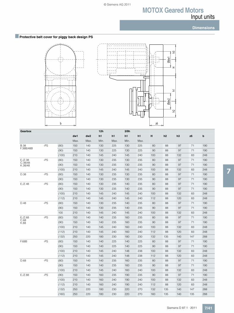
MOTOX Geared MotorsInput units
Dimensions
7/41Siemens D 87.1 · 2011
7
■ Protective belt cover for piggy back design PS
Gearbox 12h 3/9h
dw1 dw2 h1 h1 h1 h1 H h2 h3 z6 b
Max. Max. Min. Max. Min. Max.
B.38F.38B/48B
-PS (80) 150 140 130 225 130 225 80 88 97 71 190
(90) 150 140 130 225 130 225 90 88 97 71 190
(100) 210 140 145 240 145 240 100 88 132 83 248
E./Z.38C.38/48K.38/48
-PS (80) 150 140 130 235 130 235 80 88 97 71 190
(90) 150 140 130 235 130 235 90 88 97 71 190
(100) 210 140 145 240 145 240 100 88 132 83 248
D.38 -PS (80) 150 140 130 235 130 235 80 88 97 71 190
(90) 150 140 130 235 130 235 90 88 97 71 190
E./Z.48 -PS (80) 150 140 130 235 140 235 80 88 97 71 190
(90) 150 140 130 235 140 235 90 88 97 71 190
(100) 210 140 145 240 145 240 100 88 132 83 248
(112) 210 140 145 240 145 240 112 88 120 83 248
D.48 -PS (80) 150 140 130 235 140 235 80 88 97 71 190
(90) 150 140 130 235 140 235 90 88 97 71 190
100 210 140 145 240 145 240 100 88 132 83 248
E./Z.68C.68K.68
-PS (80) 150 140 140 235 160 235 80 88 97 71 190
(90) 150 140 140 235 160 235 90 88 97 71 190
(100) 210 140 145 240 160 240 100 88 132 83 248
(112) 210 140 145 240 160 240 112 88 120 83 248
(132) 250 220 180 230 180 230 132 135 140 147 288
F.68B -PS (80) 150 140 140 225 140 225 80 88 97 71 190
(90) 150 140 140 225 140 225 90 88 97 71 190
(100) 210 140 145 240 148 238 100 88 132 83 248
(112) 210 140 145 240 148 238 112 88 120 83 248
D.68 -PS (80) 150 140 140 235 160 235 80 88 97 71 190
(90) 150 140 140 235 160 235 90 88 97 71 190
(100) 210 140 145 240 160 240 100 88 132 83 248
E./Z.88 -PS (90) 150 140 160 235 190 235 90 88 97 71 190
(100) 210 140 160 240 190 240 100 88 132 83 248
(112) 210 140 160 240 190 240 112 88 120 83 248
(132) 250 220 180 230 220 270 132 135 140 147 288
(160) 250 220 180 230 220 270 160 135 140 135 288
h1H
z6b
h2h3
Ødw
2Ød
w1
© Siemens AG 2011

MOTOX Geared MotorsInput units
Dimensions
7/42 Siemens D 87.1 · 2011
7
■ Protective belt cover for piggy back design PS (continued)
Gearbox 12h 3/9h
dw1 dw2 h1 h1 h1 h1 H h2 h3 z6 b
Max. Max. Min. Max. Min. Max.
F.88B -PS (80) 150 140 163 228 168 228 80 88 97 71 190
(90) 150 140 163 228 168 228 90 88 97 71 190
(100) 210 140 163 238 160 240 100 88 132 83 248
(112) 210 140 163 238 160 240 112 88 120 83 248
(132) 250 220 178 228 188 228 132 135 140 147 288
C.88 -PS (80) 150 140 160 235 190 235 80 88 97 71 190
(90) 150 140 160 235 190 235 90 88 97 71 190
(100) 210 140 160 240 190 240 100 88 132 83 248
(112) 210 140 160 240 190 240 112 88 120 83 248
(132) 250 220 180 230 180 230 132 135 140 147 288
K.88 -PS (80) 150 140 160 235 190 235 80 88 97 71 190
(90) 150 140 160 235 190 235 90 88 97 71 190
(100) 210 140 160 240 190 240 100 88 132 83 248
(112) 210 140 160 240 190 240 112 88 120 83 248
(132) 250 220 180 230 180 230 132 135 140 147 288
D.88 -PS (80) 150 140 160 235 190 235 80 88 97 71 190
(90) 150 140 160 235 190 235 90 88 97 71 190
(100) 210 140 160 240 190 240 100 88 132 83 248
(112) 210 140 160 240 190 240 112 88 120 83 248
(132) 250 220 180 230 220 270 132 135 140 147 288
E./Z.108K.108
-PS (80) 150 140 190 300 230 300 80 88 97 71 190
(90) 150 140 190 300 230 300 90 88 97 71 190
(100) 210 140 220 320 230 320 100 88 132 83 248
(112) 210 140 220 320 230 320 112 88 120 83 248
(132) 250 220 220 270 255 305 132 135 140 147 288
(160) 250 220 220 270 255 305 160 135 140 135 288
(180) 330 310 268 352 268 352 180 205 182 134 372
(200) 330 310 268 352 268 352 200 205 182 134 372
h1H
z6b
h2h3
Ødw
2Ød
w1
© Siemens AG 2011

MOTOX Geared MotorsInput units
Dimensions
7/43Siemens D 87.1 · 2011
7
■ Protective belt cover for piggy back design PS (continued)
Gearbox 12h 3/9h
dw1 dw2 h1 h1 h1 h1 H h2 h3 z6 b
Max. Max. Min. Max. Min. Max.
F.108B -PS (80) 150 140 190 295 190 295 80 88 97.0 71 190
(90) 150 140 190 295 190 295 90 88 97.0 71 190
(100) 210 140 223 318 190 240 100 88 132.0 83 248
(112) 210 140 223 318 190 240 112 88 120.0 83 248
(132) 250 220 207 257 215 265 132 135 140.0 147 288
(160) 250 220 207 257 215 265 160 135 140.0 135 288
D.108 -PS (80) 150 140 190 300 23 300 80 88 97.0 71 190
(90) 150 140 190 300 230 300 90 88 97.0 71 190
(100) 210 140 220 320 230 320 100 88 132.0 83 248
(112) 210 140 220 320 230 320 112 88 120.0 83 248
(132) 250 220 220 270 255 305 132 135 140.0 147 288
(160) 250 220 220 270 255 305 160 135 140.0 135 288
E./Z.128 -PS (100) 210 140 220 320 255 320 100 88 132.0 83 248
(112) 210 140 220 320 255 320 112 88 120.0 83 248
(132) 250 220 255 305 280 330 132 135 140.0 147 288
(160) 250 220 255 305 280 330 160 135 140.0 135 288
(180) 330 310 253 352 293 352 180 205 182.0 134 372
(200) 330 310 253 352 293 352 200 205 182.0 134 372
(225) 390 390 295 340 – – 225 215 232.5 174 428
F.128B -PS (90) 150 140 235 295 230 295 90 88 97.0 71 190
(100) 210 140 250 320 235 320 100 88 132.0 83 248
(112) 210 140 250 320 235 320 112 88 120.0 83 248
(132) 250 220 265 365 285 365 132 135 140.0 147 288
(160) 250 220 265 365 285 330 160 135 140.0 135 288
(180) 330 310 268 358 268 358 180 205 182.0 134 372
(200) 330 310 268 358 268 358 200 205 182.0 134 372
K.128 -PS (90) 150 140 230 300 255 300 90 88 97.0 71 190
(100) 210 140 220 320 255 320 100 88 132.0 83 248
(112) 210 140 220 320 255 320 112 88 120.0 83 248
(132) 250 220 220 270 255 305 132 135 140.0 147 288
(160) 250 220 220 270 255 305 160 135 140.0 135 288
(180) 330 310 243 352 243 352 180 205 182.0 134 372
(200) 330 310 243 352 243 352 200 205 182.0 134 372
h1H
z6b
h2h3
Ødw
2Ød
w1
© Siemens AG 2011
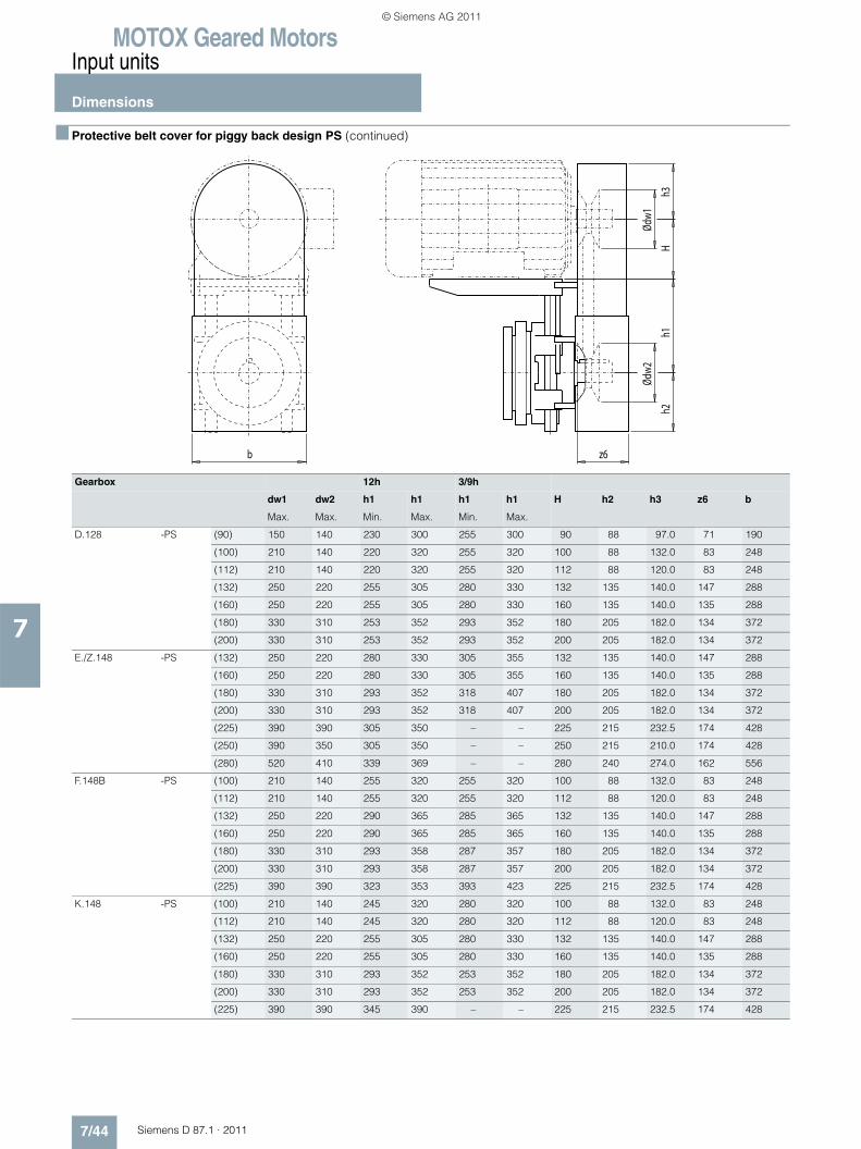
MOTOX Geared MotorsInput units
Dimensions
7/44 Siemens D 87.1 · 2011
7
■ Protective belt cover for piggy back design PS (continued)
Gearbox 12h 3/9h
dw1 dw2 h1 h1 h1 h1 H h2 h3 z6 b
Max. Max. Min. Max. Min. Max.
D.128 -PS (90) 150 140 230 300 255 300 90 88 97.0 71 190
(100) 210 140 220 320 255 320 100 88 132.0 83 248
(112) 210 140 220 320 255 320 112 88 120.0 83 248
(132) 250 220 255 305 280 330 132 135 140.0 147 288
(160) 250 220 255 305 280 330 160 135 140.0 135 288
(180) 330 310 253 352 293 352 180 205 182.0 134 372
(200) 330 310 253 352 293 352 200 205 182.0 134 372
E./Z.148 -PS (132) 250 220 280 330 305 355 132 135 140.0 147 288
(160) 250 220 280 330 305 355 160 135 140.0 135 288
(180) 330 310 293 352 318 407 180 205 182.0 134 372
(200) 330 310 293 352 318 407 200 205 182.0 134 372
(225) 390 390 305 350 – – 225 215 232.5 174 428
(250) 390 350 305 350 – – 250 215 210.0 174 428
(280) 520 410 339 369 – – 280 240 274.0 162 556
F.148B -PS (100) 210 140 255 320 255 320 100 88 132.0 83 248
(112) 210 140 255 320 255 320 112 88 120.0 83 248
(132) 250 220 290 365 285 365 132 135 140.0 147 288
(160) 250 220 290 365 285 365 160 135 140.0 135 288
(180) 330 310 293 358 287 357 180 205 182.0 134 372
(200) 330 310 293 358 287 357 200 205 182.0 134 372
(225) 390 390 323 353 393 423 225 215 232.5 174 428
K.148 -PS (100) 210 140 245 320 280 320 100 88 132.0 83 248
(112) 210 140 245 320 280 320 112 88 120.0 83 248
(132) 250 220 255 305 280 330 132 135 140.0 147 288
(160) 250 220 255 305 280 330 160 135 140.0 135 288
(180) 330 310 293 352 253 352 180 205 182.0 134 372
(200) 330 310 293 352 253 352 200 205 182.0 134 372
(225) 390 390 345 390 – – 225 215 232.5 174 428
h1H
z6b
h2h3
Ødw
2Ød
w1
© Siemens AG 2011
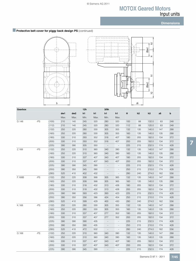
MOTOX Geared MotorsInput units
Dimensions
7/45Siemens D 87.1 · 2011
7
■ Protective belt cover for piggy back design PS (continued)
Gearbox 12h 3/9h
dw1 dw2 h1 h1 h1 h1 H h2 h3 z6 b
Max. Max. Min. Max. Min. Max.
D.148 -PS (100) 210 140 245 320 280 320 100 88 132.0 83 248
(112) 210 140 245 320 280 320 112 88 120.0 83 248
(132) 250 220 280 330 305 355 132 135 140.0 147 288
(160) 250 220 280 330 305 355 160 135 140.0 135 288
(180) 330 310 293 352 318 407 180 205 182.0 134 372
(200) 330 310 293 352 318 407 200 205 182.0 134 372
(225) 390 390 305 350 – – 225 215 232.5 174 428
Z.168 -PS (132) 250 220 310 360 340 390 132 135 140.0 147 288
(160) 250 220 310 360 340 390 160 135 140.0 135 288
(180) 330 310 337 407 343 407 180 205 182.0 134 372
(200) 330 310 337 407 343 407 200 205 182.0 134 372
(225) 390 390 345 390 – – 225 215 232.5 174 428
(250) 390 350 345 390 – – 250 215 210.0 174 428
(280) 520 410 402 432 – – 280 240 274.0 162 556
F.168B -PS (132) 250 220 308 368 305 365 132 135 140.0 147 288
(160) 250 220 308 368 305 365 160 135 140.0 135 288
(180) 330 310 318 432 313 428 180 205 182.0 134 372
(200) 330 310 318 432 313 428 200 205 182.0 134 372
(225) 390 390 393 423 393 423 225 215 232.5 174 428
(250) 390 350 356 386 424 454 250 215 210.0 174 428
(280) 520 410 399 429 400 430 280 240 274.0 162 556
K.168 -PS (132) 250 220 280 330 305 355 132 135 140.0 147 288
(160) 250 220 280 330 305 355 160 135 140.0 135 288
(180) 330 310 337 407 277 352 180 205 182.0 134 372
(200) 330 310 337 407 277 352 200 205 182.0 134 372
(225) 390 390 390 435 – – 225 215 232.5 174 428
(250) 390 350 390 435 – – 250 215 210.0 174 428
(280) 520 410 472 502 – – 280 240 274.0 162 556
D.168 -PS (132) 250 220 310 360 340 390 132 135 140.0 147 288
(160) 250 220 310 360 340 390 160 135 140.0 135 288
(180) 330 310 337 407 343 407 180 205 182.0 134 372
(200) 330 310 337 407 343 407 200 205 182.0 134 372
(225) 390 390 345 390 – – 225 215 232.5 174 428
h1H
z6b
h2h3
Ødw
2Ød
w1
© Siemens AG 2011
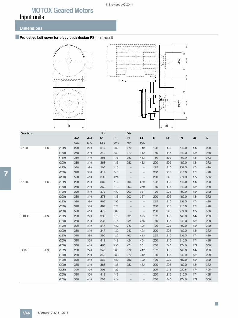
MOTOX Geared MotorsInput units
Dimensions
7/46 Siemens D 87.1 · 2011
7
■ Protective belt cover for piggy back design PS (continued)
Gearbox 12h 3/9h
dw1 dw2 h1 h1 h1 h1 H h2 h3 z6 b
Max. Max. Min. Max. Min. Max.
Z.188 -PS (132) 250 220 340 380 372 412 132 135 140.0 147 288
(160) 250 220 340 380 372 412 160 135 140.0 135 288
(180) 330 310 368 433 382 432 180 205 182.0 134 372
(200) 330 310 368 433 382 432 200 205 182.0 134 372
(225) 390 390 393 423 – – 225 215 232.5 174 428
(250) 390 350 418 448 – – 250 215 210.0 174 428
(280) 520 410 399 424 – – 280 240 274.0 177 556
K.188 -PS (132) 250 220 360 410 300 370 132 135 140.0 147 288
(160) 250 220 360 410 300 370 160 135 140.0 135 288
(180) 330 310 378 433 302 357 180 205 182.0 134 372
(200) 330 310 378 433 302 357 200 205 182.0 134 372
(225) 390 390 463 493 – – 225 215 232.5 174 428
(250) 390 350 493 523 – – 250 215 210.0 174 428
(280) 520 410 472 502 – – 280 240 274.0 177 556
F.188B -PS (132) 250 220 335 375 335 375 132 135 140.0 147 288
(160) 250 220 335 375 335 375 160 135 140.0 135 288
(180) 330 310 347 432 343 428 180 205 182.0 134 372
(200) 330 310 347 432 343 428 200 205 182.0 134 372
(225) 390 390 390 420 463 493 225 215 232.5 174 428
(250) 390 350 419 449 424 454 250 215 210.0 174 428
(280) 520 410 463 493 471 501 280 240 274.0 177 556
D.188 -PS (132) 250 220 340 380 372 412 132 135 140.0 147 288
(160) 250 220 340 380 372 412 160 135 140.0 135 288
(180) 330 310 368 433 382 432 180 205 182.0 134 372
(200) 330 310 368 433 382 432 200 205 182.0 134 372
(225) 390 390 393 423 – – 225 215 232.5 174 428
(250) 390 350 418 448 – – 250 215 210.0 174 428
(280) 520 410 399 424 – – 280 240 274.0 177 556
h1H
z6b
h2h3
Ødw
2Ød
w1
© Siemens AG 2011
Siemens D 87.1 · 2011
99/2 Partner at Industry Automation and
Drive Technologies
9/3 Information and Ordering in the Internet and on DVD
9/4 Service & Support
9/12 Conditions of sale and delivery Export regulations
Appendix
© Siemens AG 2011
MOTOX Geared MotorsPartner at Industry Automation and Drive Technologies
9/2 Siemens D 87.1 · 2011
9
At Siemens Industry Automation and Drive Technologies, more than 85 000 people are resolutely pursuing the same goal: long-term improvement of your competitive ability. We are committed to this goal. Thanks to our commitment, we continue to set new standards in automation and drive technol-ogy. In all industries – worldwide.
At your service locally, around the globe for consulting, sales, training, service, support, spare parts ... on the entire Industry Automation and Drive Technologies range.
Your personal contact can be found in our Contacts Database at:www.siemens.com/automation/partner
You start by selecting a• Product group, • Country, • City, • Service.
© Siemens AG 2011

MOTOX Geared MotorsOnline Services
Information and Orderingin the Internet and on DVD
9/3Siemens D 87.1 · 2011
9
■ Siemens Industry Automation and Drive Technologies in the WWW
A detailed knowledge of the range of products and services available is essential when planning and configuring automation systems. It goes without saying that this information must always be fully up-to-date.
Siemens Industry Automation and Drive Technologies has therefore built up a comprehensive range of information in the World Wide Web, which offers quick and easy access to all data required.
Under the address
www.siemens.com/industry
you will find everything you need to know about products, systems and services.
■ Product Selection Using the Offline Mall of Industry
Detailed information together with convenient interactive functions: The Offline Mall CA 01 covers more than 80 000 products and thus provides a full summary of the Siemens Industry Automation and Drive Technologies product base.
Here you will find everything that you need to solve tasks in the fields of automation, switchgear, installation and drives. All information is linked into a user interface which is easy to work with and intuitive.
After selecting the product of your choice you can order at the press of a button, by fax or by online link.
Information on the Offline Mall CA 01 can be found in the Internet under
www.siemens.com/automation/ca01
or on DVD.
■ Easy Shopping with the Industry Mall
The Industry Mall is the virtual department store of Siemens AG in the Internet. Here you have access to a huge range of prod-ucts presented in electronic catalogs in an informative and at-tractive way.
Data transfer via EDIFACT allows the whole procedure from selection through ordering to tracking of the order to be carried out online via the Internet.
Numerous functions are available to support you.
For example, powerful search functions make it easy to find the required products, which can be immediately checked for avail-ability. Customer-specific discounts and preparation of quotes can be carried out online as well as order tracking and tracing.
Please visit the Industry Mall on the Internet under:
www.siemens.com/industrymall
© Siemens AG 2011
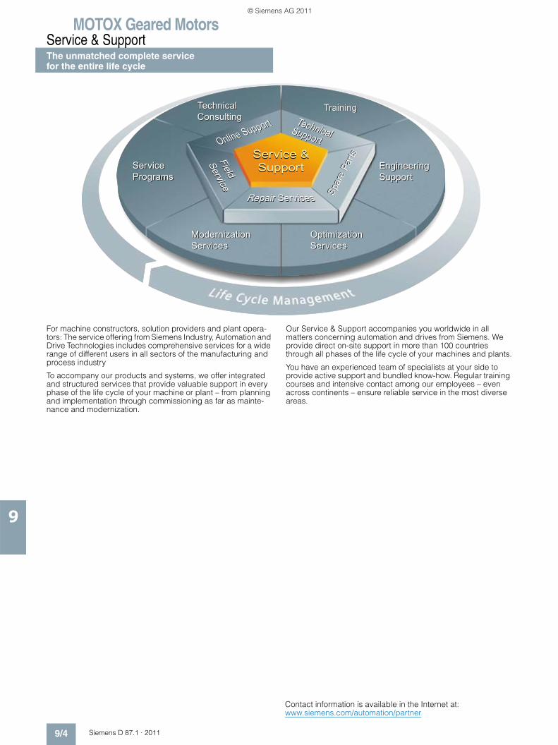
MOTOX Geared MotorsService & SupportThe unmatched complete service for the entire life cycle
9/4 Siemens D 87.1 · 2011
9
For machine constructors, solution providers and plant opera-tors: The service offering from Siemens Industry, Automation and Drive Technologies includes comprehensive services for a wide range of different users in all sectors of the manufacturing and process industry
To accompany our products and systems, we offer integrated and structured services that provide valuable support in every phase of the life cycle of your machine or plant – from planning and implementation through commissioning as far as mainte-nance and modernization.
Our Service & Support accompanies you worldwide in all matters concerning automation and drives from Siemens. We provide direct on-site support in more than 100 countries through all phases of the life cycle of your machines and plants.
You have an experienced team of specialists at your side to provide active support and bundled know-how. Regular training courses and intensive contact among our employees – even across continents – ensure reliable service in the most diverse areas.
Spar
e Pa
rts
Spar
e Pa
rts
TechnicalSupport
TechnicalConsultingTechnicalConsulting TechnicalSupport
Service ProgramsServicePrograms
Engineering SupportEngineering Support
TrainingTraining
Modernization ServicesModernization Services
Online Support
Online Support
Field
ServiceField
Service
Optimization Services Optimization Services
Contact information is available in the Internet at: www.siemens.com/automation/partner
© Siemens AG 2011

MOTOX Geared MotorsService & Support
The unmatched complete servicefor the entire life cycle
9/5Siemens D 87.1 · 2011
9
■ Online SupportThe comprehensive online infor-mation platform supports you in all aspects of our Service & Sup-port at any time and from any location in the world.
www.siemens.com/automation/service&support
■ Technical SupportExpert advice on technical questions with a wide range of demand-optimized services for all our products and systems.
www.siemens.com/automation/support-request
■ Technical ConsultingSupport in planning and design-ing your project: From detailed actual-state analysis, definition of the goal and consulting on product and system questions right through to the creation of the automation solution.
■ TrainingExtend your competitive edge – through practical know-how directly from the manufacturer.
www.siemens.com/sitrain
Contact information is available in the Internet at: www.siemens.com/automation/partner
© Siemens AG 2011
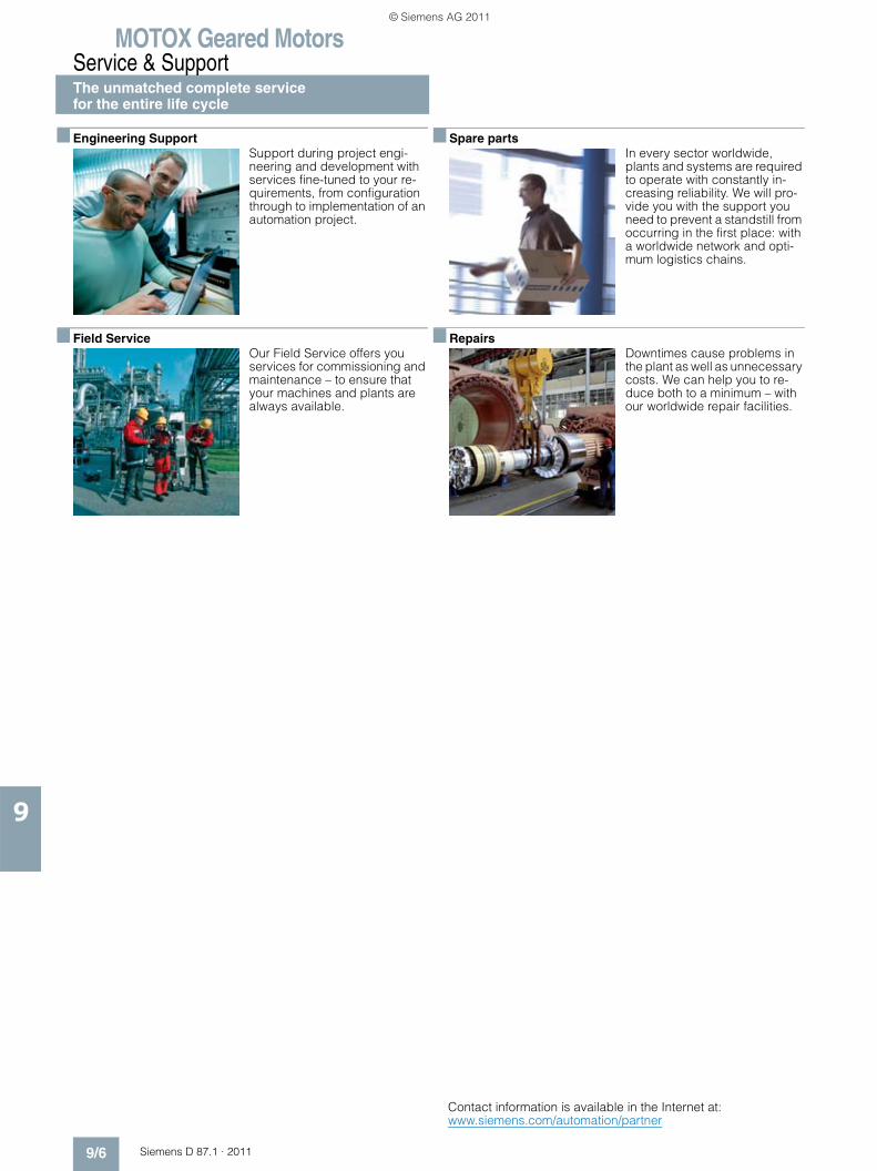
MOTOX Geared MotorsService & SupportThe unmatched complete service for the entire life cycle
9/6 Siemens D 87.1 · 2011
9
■ Engineering SupportSupport during project engi-neering and development with services fine-tuned to your re-quirements, from configuration through to implementation of an automation project.
■ Field ServiceOur Field Service offers you services for commissioning and maintenance – to ensure that your machines and plants are always available.
■ Spare partsIn every sector worldwide, plants and systems are required to operate with constantly in-creasing reliability. We will pro-vide you with the support you need to prevent a standstill from occurring in the first place: with a worldwide network and opti-mum logistics chains.
■ RepairsDowntimes cause problems in the plant as well as unnecessary costs. We can help you to re-duce both to a minimum – with our worldwide repair facilities.
Contact information is available in the Internet at: www.siemens.com/automation/partner
© Siemens AG 2011
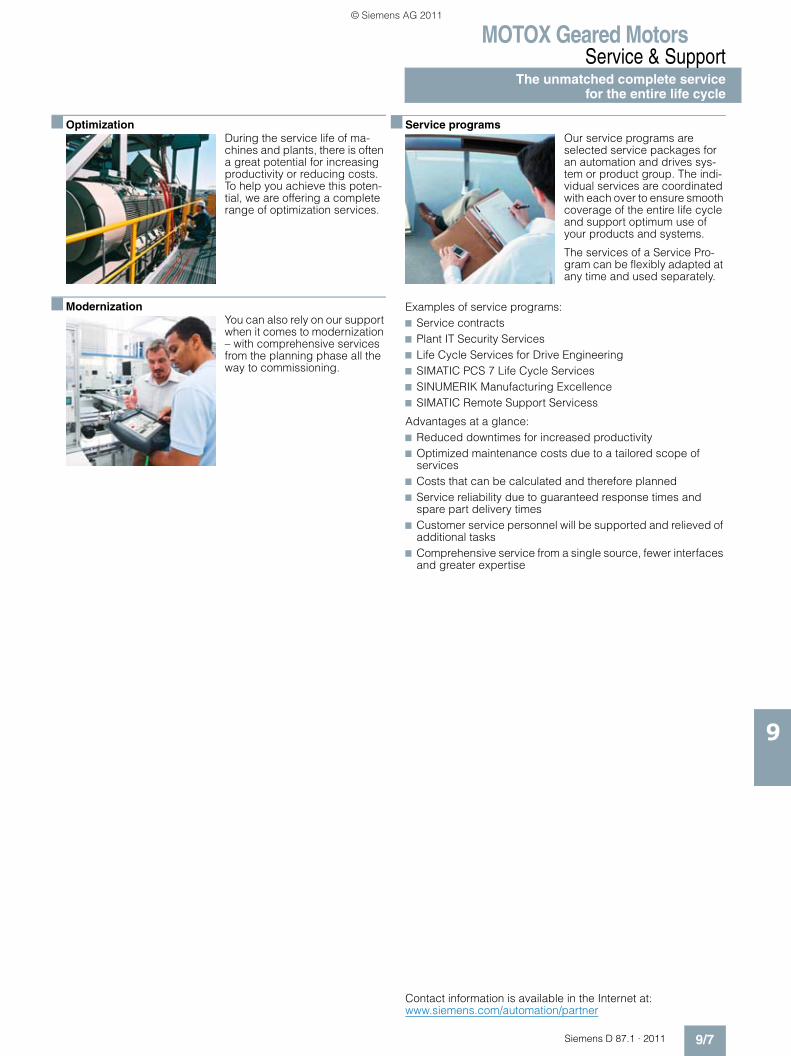
MOTOX Geared MotorsService & Support
The unmatched complete servicefor the entire life cycle
9/7Siemens D 87.1 · 2011
9
■ OptimizationDuring the service life of ma-chines and plants, there is often a great potential for increasing productivity or reducing costs. To help you achieve this poten-tial, we are offering a complete range of optimization services.
■ ModernizationYou can also rely on our support when it comes to modernization – with comprehensive services from the planning phase all the way to commissioning.
■ Service programsOur service programs are selected service packages for an automation and drives sys-tem or product group. The indi-vidual services are coordinated with each over to ensure smooth coverage of the entire life cycle and support optimum use of your products and systems.
The services of a Service Pro-gram can be flexibly adapted at any time and used separately.
Examples of service programs:7 Service contracts7 Plant IT Security Services7 Life Cycle Services for Drive Engineering7 SIMATIC PCS 7 Life Cycle Services7 SINUMERIK Manufacturing Excellence7 SIMATIC Remote Support Servicess
Advantages at a glance:7 Reduced downtimes for increased productivity7 Optimized maintenance costs due to a tailored scope of
services7 Costs that can be calculated and therefore planned7 Service reliability due to guaranteed response times and
spare part delivery times7 Customer service personnel will be supported and relieved of
additional tasks7 Comprehensive service from a single source, fewer interfaces
and greater expertise
Contact information is available in the Internet at: www.siemens.com/automation/partner
© Siemens AG 2011
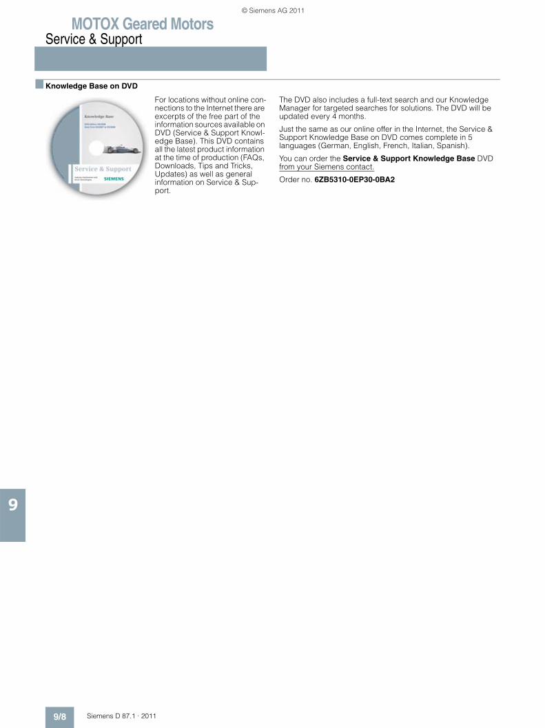
MOTOX Geared MotorsService & Support
9/8 Siemens D 87.1 · 2011
9
■ Knowledge Base on DVD
For locations without online con-nections to the Internet there are excerpts of the free part of the information sources available on DVD (Service & Support Knowl-edge Base). This DVD contains all the latest product information at the time of production (FAQs, Downloads, Tips and Tricks, Updates) as well as general information on Service & Sup-port.
The DVD also includes a full-text search and our Knowledge Manager for targeted searches for solutions. The DVD will be updated every 4 months.
Just the same as our online offer in the Internet, the Service & Support Knowledge Base on DVD comes complete in 5 languages (German, English, French, Italian, Spanish).
You can order the Service & Support Knowledge Base DVD from your Siemens contact.
Order no. 6ZB5310-0EP30-0BA2
© Siemens AG 2011
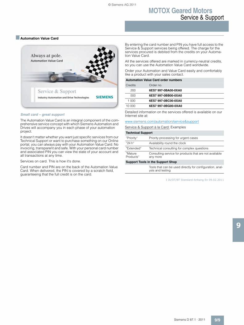
MOTOX Geared MotorsService & Support
9/9Siemens D 87.1 · 2011
9
■ Automation Value Card
Small card – great support
The Automation Value Card is an integral component of the com-prehensive service concept with which Siemens Automation and Drives will accompany you in each phase of your automation project.
It doesn't matter whether you want just specific services from our Technical Support or want to purchase something on our Online portal, you can always pay with your Automation Value Card. No invoicing, transparent and safe. With your personal card number and associated PIN you can view the state of your account and all transactions at any time.
Services on card. This is how it's done.
Card number and PIN are on the back of the Automation Value Card. When delivered, the PIN is covered by a scratch field, guaranteeing that the full credit is on the card.
By entering the card number and PIN you have full access to the Service & Support services being offered. The charge for the services procured is debited from the credits on your Automa-tion Value Card.
All the services offered are marked in currency-neutral credits, so you can use the Automation Value Card worldwide.
Order your Automation and Value Card easily and comfortably like a product with your sales contact.
Detailed information on the services offered is available on our Internet site at:
www.siemens.com/automation/service&support
Service & Support à la Card: Examples
I IA/DT/BT Standard-Anhang En 09.02.2011
Automation Value Card order numbers
Credits Order no.
200 6ES7 997-0BA00-0XA0
500 6ES7 997-0BB00-0XA0
1 000 6ES7 997-0BC00-0XA0
10 000 6ES7 997-0BG00-0XA0
Technical Support
”Priority“ Priority processing for urgent cases
”24 h“ Availability round the clock
”Extended“ Technical consulting for complex questions
”Mature Products“
Consulting service for products that are not available any more
Support Tools in the Support Shop
Tools that can be used directly for configuration, anal-ysis and testing
© Siemens AG 2011
MOTOX Geared MotorsAppendix
Notes
9/10 Siemens D 87.1 · 2011
9
© Siemens AG 2011
MOTOX Geared MotorsAppendix
Notes
9/11Siemens D 87.1 · 2011
9
© Siemens AG 2011
MOTOX Geared MotorsAppendixConditions of sale and delivery Export regulations
9/12 Siemens D 87.1 · 2011
9
■ Terms and Conditions of Sale and Delivery
By using this catalog you can acquire hardware and software products described therein from Siemens AG subject to the fol-lowing terms. Please note! The scope, the quality and the condi-tions for supplies and services, including software products, by any Siemens entity having a registered office outside of Ger-many, shall be subject exclusively to the General Terms and Conditions of the respective Siemens entity. The following terms apply exclusively for orders placed with Siemens AG.
For customers with a seat or registered office in GermanyThe “General Terms of Payment” as well as the “General Condi-tions for the Supply of Products and Services of the Electrical and Electronics Industry” shall apply.For software products, the “General License Conditions for Soft-ware Products for Automation and Drives for Customers with a Seat or registered Office in Germany” shall apply.
For customers with a seat or registered office outside of GermanyThe “General Terms of Payment” as well as the “General Condi-tions for Supplies of Siemens, Automation and Drives for Cus-tomers with a Seat or registered Office outside of Germany” shall apply.For software products, the “General License Conditions for Soft-ware Products for Automation and Drives for Customers with a Seat or registered Office outside of Germany” shall apply.
GeneralThe dimensions are in mm. In Germany, according to the Ger-man law on units in measuring technology, data in inches only apply to devices for export. Illustrations are not binding.Insofar as there are no remarks on the corresponding pages, - especially with regard to data, dimensions and weights given – these are subject to change without prior notice.The prices are in € (Euro) ex works, exclusive packaging.The sales tax (value added tax) is not included in the prices. It shall be debited separately at the respective rate according to the applicable legal regulations.Prices are subject to change without prior notice. We will debit the prices valid at the time of delivery.Surcharges will be added to the prices of products that contain silver, copper, aluminum, lead and/or gold if the respective basic official prices for these metals are exceeded. These surcharges will be determined based on the official price and the metal fac-tor of the respective product.The surcharge will be calculated on the basis of the official price on the day prior to receipt of the order or prior to the release order.The metal factor determines the official price as of which the metal surcharges are charged and the calculation method used. The metal factor, provided it is relevant, is included with the price information of the respective products.
An exact explanation of the metal factor and the text of the Comprehensive Terms and Conditions of Sale and Delivery are available free of charge from your local Siemens business office under the following Order Nos.:• 6ZB5310-0KR30-0BA1
(for customers based in Germany)• 6ZB5310-0KS53-0BA1
(for customers based outside Germany)or download them from the Internetwww.siemens.com/industrymall (Germany: Industry Mall Online-Help System)
■ Export regulations
Our obligation to fulfill this agreement is subject to the proviso that the fulfillment is not prevented by any impediments arising out of national and international foreign trade and customs requirements or any embargos and/or other sanctions.If you transfer goods (hardware and/ or software and/ or tech-nology as well as corresponding documentation, regardless of the mode of provision) delivered by us or works and services (including all kinds of technical support) performed by us to a third party worldwide, you shall comply with all applicable national and international (re-) export control regulations. If required to conduct export control checks, you, upon request by us, shall promptly provide us with all information pertaining to particular end customer, destination and intended use of goods, works and services provided by us, as well as any export control restrictions existing.The products listed in this catalog may be subject to European / German and/or US export regulations.Therefore, any export requiring a license is subject to approval by the competent authorities.According to current provisions, the following export regulations must be observed with respect to the products featured in this catalog:
Even without a label or with an “AL: N” or “ECCN: N”, authoriza-tion may be required due to the final destination and purpose for which the goods are to be used. The deciding factors are the AL or ECCN export authorization indicated on order confirmations, delivery notes and invoices.Errors excepted and subject to change without prior notice.
IA/DT/BT VuL_ohne MZ En 07.07.10
AL Number of the German Export ListProducts marked other than “N” require an export license. In the case of software products, the export des-ignations of the relevant data medium must also be generally adhered to.Goods labeled with an “AL“ not equal to “N” are subject to a European or German export authori-zation when being exported out of the EU.
ECCN Export Control Classification NumberProducts marked other than “N” are subject to a reexport license to specific countries.In the case of software products, the exportdesignations of the relevant data medium must also be generally adhered to.Goods labeled with an “ECCN“ not equal to “N” are subject to a US re-export authorization.
© Siemens AG 2011
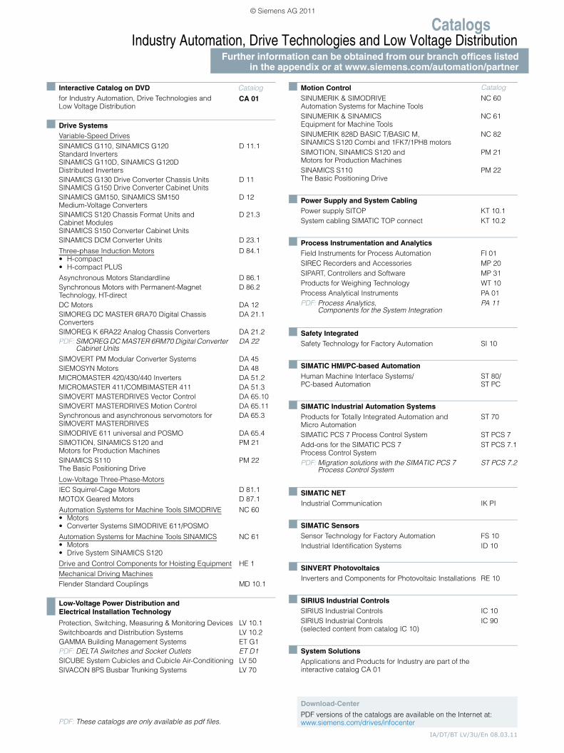
CatalogsIndustry Automation, Drive Technologies and Low Voltage Distribution
Further information can be obtained from our branch offices listedin the appendix or at www.siemens.com/automation/partner
IA/DT/BT LV/3U/En 08.03.11
Interactive Catalog on DVD Catalogfor Industry Automation, Drive Technologies and Low Voltage Distribution
CA 01
Drive SystemsVariable-Speed DrivesSINAMICS G110, SINAMICS G120 Standard Inverters SINAMICS G110D, SINAMICS G120D Distributed Inverters
D 11.1
SINAMICS G130 Drive Converter Chassis Units SINAMICS G150 Drive Converter Cabinet Units
D 11
SINAMICS GM150, SINAMICS SM150 Medium-Voltage Converters
D 12
SINAMICS S120 Chassis Format Units and Cabinet Modules SINAMICS S150 Converter Cabinet Units
D 21.3
SINAMICS DCM Converter Units D 23.1
Three-phase Induction Motors• H-compact• H-compact PLUS
D 84.1
Asynchronous Motors Standardline D 86.1Synchronous Motors with Permanent-Magnet Technology, HT-direct
D 86.2
DC Motors DA 12SIMOREG DC MASTER 6RA70 Digital Chassis Converters
DA 21.1
SIMOREG K 6RA22 Analog Chassis Converters DA 21.2PDF: SIMOREG DC MASTER 6RM70 Digital Converter
Cabinet UnitsDA 22
SIMOVERT PM Modular Converter Systems DA 45SIEMOSYN Motors DA 48MICROMASTER 420/430/440 Inverters DA 51.2MICROMASTER 411/COMBIMASTER 411 DA 51.3SIMOVERT MASTERDRIVES Vector Control DA 65.10SIMOVERT MASTERDRIVES Motion Control DA 65.11Synchronous and asynchronous servomotors for SIMOVERT MASTERDRIVES
DA 65.3
SIMODRIVE 611 universal and POSMO DA 65.4SIMOTION, SINAMICS S120 and Motors for Production Machines
PM 21
SINAMICS S110 The Basic Positioning Drive
PM 22
Low-Voltage Three-Phase-MotorsIEC Squirrel-Cage Motors D 81.1MOTOX Geared Motors D 87.1
Automation Systems for Machine Tools SIMODRIVE• Motors• Converter Systems SIMODRIVE 611/POSMO
NC 60
Automation Systems for Machine Tools SINAMICS• Motors• Drive System SINAMICS S120
NC 61
Drive and Control Components for Hoisting Equipment HE 1Mechanical Driving MachinesFlender Standard Couplings MD 10.1
Low-Voltage Power Distribution and Electrical Installation Technology
Protection, Switching, Measuring & Monitoring Devices LV 10.1Switchboards and Distribution Systems LV 10.2GAMMA Building Management Systems ET G1PDF: DELTA Switches and Socket Outlets ET D1SICUBE System Cubicles and Cubicle Air-Conditioning LV 50SIVACON 8PS Busbar Trunking Systems LV 70
PDF: These catalogs are only available as pdf files.
Motion Control Catalog
SINUMERIK & SIMODRIVE Automation Systems for Machine Tools
NC 60
SINUMERIK & SINAMICS Equipment for Machine Tools
NC 61
SINUMERIK 828D BASIC T/BASIC M, SINAMICS S120 Combi and 1FK7/1PH8 motors
NC 82
SIMOTION, SINAMICS S120 and Motors for Production Machines
PM 21
SINAMICS S110 The Basic Positioning Drive
PM 22
Power Supply and System CablingPower supply SITOP KT 10.1System cabling SIMATIC TOP connect KT 10.2
Process Instrumentation and AnalyticsField Instruments for Process Automation FI 01SIREC Recorders and Accessories MP 20SIPART, Controllers and Software MP 31Products for Weighing Technology WT 10Process Analytical Instruments PA 01PDF: Process Analytics,
Components for the System IntegrationPA 11
Safety IntegratedSafety Technology for Factory Automation SI 10
SIMATIC HMI/PC-based AutomationHuman Machine Interface Systems/PC-based Automation
ST 80/ ST PC
SIMATIC Industrial Automation SystemsProducts for Totally Integrated Automation and Micro Automation
ST 70
SIMATIC PCS 7 Process Control System ST PCS 7Add-ons for the SIMATIC PCS 7 Process Control System
ST PCS 7.1
PDF: Migration solutions with the SIMATIC PCS 7 Process Control System
ST PCS 7.2
SIMATIC NETIndustrial Communication IK PI
SIMATIC SensorsSensor Technology for Factory Automation FS 10Industrial Identification Systems ID 10
SINVERT PhotovoltaicsInverters and Components for Photovoltaic Installations RE 10
SIRIUS Industrial Controls SIRIUS Industrial Controls IC 10SIRIUS Industrial Controls (selected content from catalog IC 10)
IC 90
System SolutionsApplications and Products for Industry are part of the interactive catalog CA 01
Download-Center
PDF versions of the catalogs are available on the Internet at:www.siemens.com/drives/infocenter
© Siemens AG 2011

The information provided in this catalog contains descriptions orcharacteristics of performance which in case of actual use do notalways apply as described or which may change as a result offurther development of the products. An obligation to provide therespective characteristics shall only exist if expressly agreed in theterms of contract. Availability and technical specifications aresubject to change without notice.All product designations may be trademarks or product names ofSiemens AG or supplier companies whose use by third parties fortheir own purposes could violate the rights of the owners.
Token fee: 5.00 €www.siemens.com/motors
Subject to change without prior noticeOrder No.: E86060-K5287-A111-A4-7600Dispo 18409 / 3P.8322.80.18KG 0311 10.0 K 1008 EnPrinted in Germany © Siemens AG 2011
Siemens AGIndustry SectorDrive Technologies DivisionMechanical DrivesPostfach 170972007 TÜBINGENGERMANY
© Siemens AG 2011

Cat
alo
g D
87
.1 ·
20
11
MO
TO
X G
eare
d M
oto
rs
© Siemens AG 2011