Embed Size (px)
Citation preview
ISSUE 2001
Motors
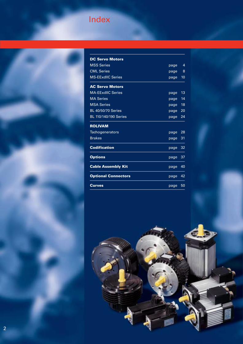
Index
DC Servo Motors
MSS Series page 4
CML Series page 8
MS-EExdIIC Series page 10
AC Servo Motors
MA-EExdIIC Series page 13
MA Series page 14
MSA Series page 18
BL 40/50/70 Series page 20
BL 110/140/190 Series page 24
ROLIVAM
Tachogenerators page 28
Brakes page 31
Codification page 32
Options page 37
Cable Assembly Kit page 40
Optional Connectors page 42
Curves page 50
2
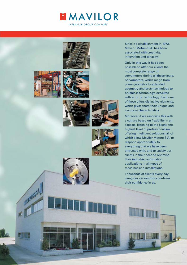
Since it’s establishment in 1973,Mavilor Motors S.A. has beenassociated with creativity,innovation and tenacity.
Only in this way it has beenpossible to offer our clients themost complete range ofservomotors during all these years.Servomotors, which range fromplane geometry to extendedgeometry and brushtechnology tobrushless technology, executedwith ac or dc technology. Each oneof these offers distinctive elements,which gives them their unique andexclusive characteristics.
Moreover if we associate this witha culture based on flexibility in allaspects, listening to the client, thehighest level of professionalism,offering intelligent solutions, all ofwhich allow Mavilor Motors S.A. torespond appropriately toeverything that we have beenentrusted with, and to satisfy ourclients in their need to optimisetheir industrial automationapplications in all types ofmachines and installations.
Thousands of clients every dayusing our servomotors confirmstheir confidence in us.
3
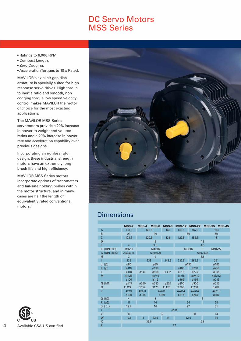
DC Servo MotorsMSS Series
• Ratings to 6,000 RPM.• Compact Length.• Zero Cogging.• Acceleration Torques to 10 x Rated.
MAVILOR's axial air gap disharmature is specially suited for highresponse servo drives. High torqueto inertia ratio and smooth, noncogging torque low speed velocitycontrol makes MAVILOR the motorof choice for the most exactingapplications.
The MAVILOR MSS Seriesservomotors provide a 20% increasein power to weight and volumeratios and a 20% increase in powerrate and acceleration capability overprevious designs.
Incorporating an ironless rotordesign, these industrial strengthmotors have an extremely longbrush life and high efficiency.
MAVILOR MSS Series motorsincorporate options of tachometersand fail-safe holding brakes withinthe motor structure, and in manycases are half the length ofequivalently rated conventionalmotors.
DimensionsTYPE
129.5
120.5
233
35.5
50
M8x16
ø130
2427
12.5
124.5
A8x7x323.5
8
33
MSS-12139.5
127.5
237.5
ø180ø2124xM8ø165ø250 206
4xø14ø215
MSS-22167.5
155.5
265.5
ø230ø275
4xM10ø165ø300 258
4xø14ø265
11
MSS-35 MSS-4519360181
M10x22
291ø180ø250ø305
4xM12ø215ø350 284
4xø18ø300
2831
1414
MSS-8140
131
243.5
ø192
ø205176
14
ABCDEF (DIN 933)G (DIN 6885)HIJ (j6)K (j6)LM
N (h11)OP
Q (h9)R (g6)S ( )TVWXZ
0-0.1
ø101
77
4xø11ø180
10
MSS-2131.5
23122.5
4M3x10
A4x4x143
235ø80ø110ø1184xM6ø100ø149119
4xø9ø130
411
12.7
810.5
MSS-6
30
93.5
M4x16A5x5x20
2
ø95ø130ø1684xM6ø115ø210 170
51416
13.5
MSS-4
ø140
ø200 1544xø11ø165
13
4 Available CSA-US certified
5
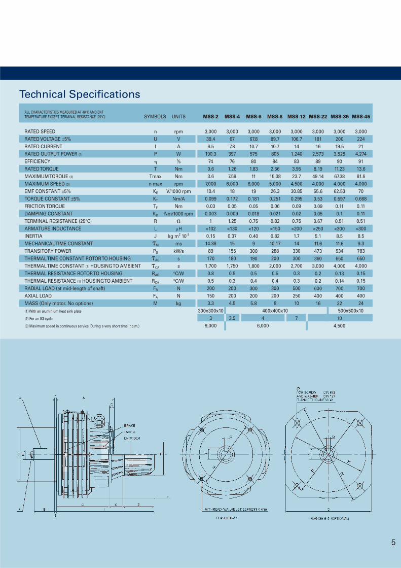
Technical Specifications
RATED SPEEDRATED VOLTAGE ±5%RATED CURRENTRATED OUTPUT POWER (1)
EFFICIENCYRATED TORQUEMAXIMUM TORQUE (2)
MAXIMUM SPEED (3)
EMF CONSTANT ±5%TORQUE CONSTANT ±5%FRICTION TORQUEDAMPING CONSTANTTERMINAL RESISTANCE (25°C)ARMATURE INDUCTANCEINERTIAMECHANICAL TIME CONSTANTTRANSITORY POWERTHERMAL TIME CONSTANT ROTOR TO HOUSINGTHERMAL TIME CONSTANT (1) HOUSING TO AMBIENTTHERMAL RESISTANCE ROTOR TO HOUSINGTHERMAL RESISTANCE (1) HOUSING TO AMBIENTRADIAL LOAD (at mid-length of shaft)AXIAL LOADMASS (Only motor. No options)(1) With an aluminium heat sink plate
(2) For an S3 cycle
(3) Maximum speed in continuous service. During a very short time (r.p.m.)
500x500x10
ALL CHARACTERISTICS MEASURED AT 40°C AMBIENTTEMPERATURE EXCEPT TERMINAL RESISTANCE (25°C)
rpmVAW%
NmNmrpm
V/1000 rpmNm/ANm
Nm/1000 rpm
Hkg m2 10-3
mskW/s
ss
°C/W°C/W
NNkg
nUIP
TTmaxn max
KE
KT
TF
KD
RLJM
PS
AC
CA
RAC
RCA
FR
FA
M
46,000
3,000677.839776
1.267.58
6,00018
0.1720.05
0.0091.25<1300.3715155180
1,7500.50.32002004.5
3.5
3,00067.810.757580
1.8311
6,00019
0.1810.050.0180.75<1200.40
9300190
1,8000.50.43002005.8
3,000106.7
141,240
833.9523.7
4,50030.850.2950.090.020.75<2001.714
330300
2,7000.30.350025010
7
3,00018116
2,57389
8.1949.144,00055.60.530.090.050.67<2505.111.6473360
3,0000.20.260040016
3,00020019.5
3,52590
11.2367.384,00062.530.5970.110.10.51<3008.511.6534650
4,0000.130.1470040022
104,500
3,00022421
4,27491
13.681.6
4,00070
0.6680.110.110.51<3008.59.3783650
4,0000.150.1570040024
3,00039.46.5
190.3740.63.6
7,00010.4
0.0990.03
0.0031
<1020.1514.38
89170
1,7000.80.52001503.3
300x300x103
9,000
3,00089.710.780584
2.5615.385,00026.3
0.2510.06
0.0210.82<1500.8210.17288200
2,0000.50.4300200
8400x400x10
SYMBOLS UNITS MSS-2 MSS-4 MSS-6 MSS-8 MSS-12 MSS-22 MSS-35 MSS-45
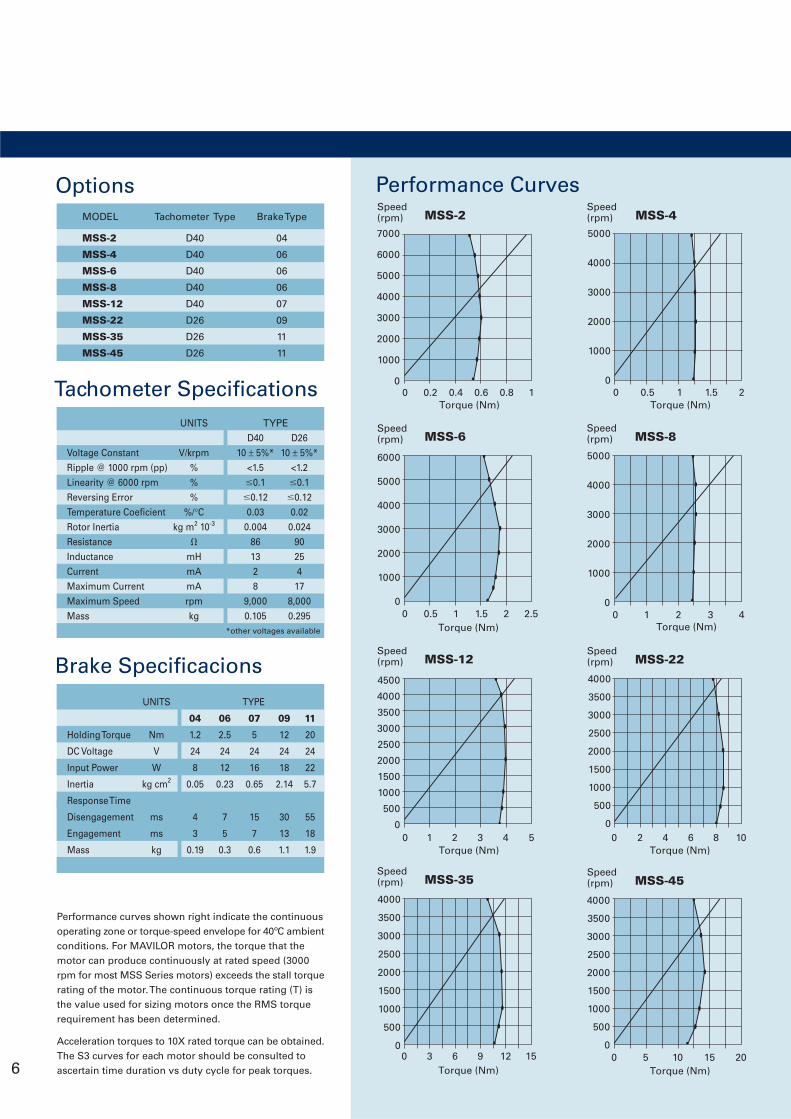
Performance curves shown right indicate the continuousoperating zone or torque-speed envelope for 40ºC ambientconditions. For MAVILOR motors, the torque that themotor can produce continuously at rated speed (3000rpm for most MSS Series motors) exceeds the stall torquerating of the motor. The continuous torque rating (T) isthe value used for sizing motors once the RMS torquerequirement has been determined.
Acceleration torques to 10X rated torque can be obtained.The S3 curves for each motor should be consulted toascertain time duration vs duty cycle for peak torques.
Performance Curves
Tachometer Specifications
Voltage ConstantRipple @ 1000 rpm (pp)Linearity @ 6000 rpmReversing ErrorTemperature CoeficientRotor InertiaResistanceInductanceCurrentMaximum CurrentMaximum SpeedMass
UNITS
V/krpm%%%
%/°Ckg m2 10-3
mHmAmArpmkg
D4010 ± 5%*
<1.50.1
0.120.03
0.004861328
9,0000.105
D2610 ± 5%*
<1.20.1
0.120.020.024
9025417
8,0000.295
TYPE
*other voltages available
OptionsMODEL Tachometer Type Brake Type
MSS-2 D40 04
MSS-4 D40 06
MSS-6 D40 06
MSS-8 D40 06
MSS-12 D40 07
MSS-22 D26 09
MSS-35 D26 11
MSS-45 D26 11
Holding Torque
DC Voltage
Input Power
Inertia
Response Time
Disengagement
Engagement
Mass
UNITS
Nm
V
W
kg cm2
ms
ms
kg
04
1.2
24
8
0.05
4
3
0.19
06
2.5
24
12
0.23
7
5
0.3
07
5
24
16
0.65
15
7
0.6
09
12
24
18
2.14
30
13
1.1
11
20
24
22
5.7
55
18
1.9
TYPE
Brake Specificacions
6000
5000
4000
3000
2000
1000
00 0.5 1 1.5 2 2.5
Torque (Nm)
MSS-6Speed(rpm)
4000
3500
3000
2500
2000
1500
1000
500
00 5 10 15 20
Torque (Nm)
MSS-45Speed(rpm)
4000
3500
3000
2500
2000
1500
1000
500
00 3 6 9 12 15
Torque (Nm)
MSS-35Speed(rpm)
4000
3500
3000
2500
2000
1500
1000
500
00 2 4 6 8 10
Torque (Nm)
MSS-22Speed(rpm)
4500
4000
3500
3000
2500
2000
1500
1000
500
00 1 2 3 4 5
Torque (Nm)
MSS-12Speed(rpm)
MSS-2Speed(rpm)
7000
6000
5000
4000
3000
2000
1000
00 0.2 0.4 0.6 0.8 1
Torque (Nm)
Torque (Nm)
5000
4000
3000
2000
1000
00 1 2 3 4
MSS-8Speed(rpm)
6
MSS-4Speed(rpm)
5000
4000
3000
2000
1000
00 0.5 1 1.5 2
Torque (Nm)
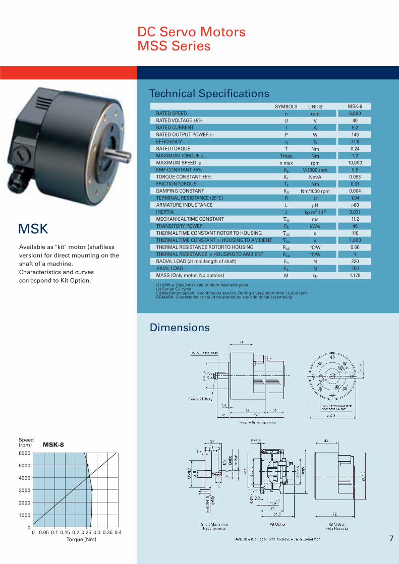
Available as "kit" motor (shaftlessversion) for direct mounting on theshaft of a machine.Characteristics and curvescorrespond to Kit Option.
Technical Specifications
Dimensions
(1) With a 300x300x10 aluminium heat sink plate(2) For an S3 cycle(3) Maximum speed in continuous service. During a very short time 12,000 rpmREMARK: Characteristics could be altered by any additional assembling
RATED SPEEDRATED VOLTAGE ±5%RATED CURRENTRATED OUTPUT POWER (1)
EFFICIENCYRATED TORQUEMAXIMUM TORQUE (2)
MAXIMUM SPEED (3)
EMF CONSTANT ±5%TORQUE CONSTANT ±5%FRICTION TORQUEDAMPING CONSTANTTERMINAL RESISTANCE (25°C)ARMATURE INDUCTANCEINERTIAMECHANICAL TIME CONSTANTTRANSITORY POWERTHERMAL TIME CONSTANT ROTOR TO HOUSINGTHERMAL TIME CONSTANT (1) HOUSING TO AMBIENTTHERMAL RESISTANCE ROTOR TO HOUSINGTHERMAL RESISTANCE (1) HOUSING TO AMBIENTRADIAL LOAD (at mid-length of shaft)AXIAL LOADMASS (Only motor. No options)
UNITSrpm
VAW%
NmNmrpm
V/1000 rpmNm/ANm
Nm/1000 rpm
µHkg m2 10-3
mskW/s
ss
°C/W°C/W
NNkg
MSK-86,000
405.214971.60.241.2
10,0005.5
0.0530.01
0.0041.04>60
0.03111.246110
1,0000.66
1220150
1.178
0 0.05 0.1 0.15 0.2 0.25 0.3 0.35 0.4Torque (Nm)
MSK-8Speed(rpm)
6000
5000
4000
3000
2000
1000
0
SYMBOLSnUIP
TTmaxn max
KE
KT
TF
KD
RLJM
PS
AC
CA
RAC
RCA
FR
FA
M
7
MSK
DC Servo MotorsMSS Series
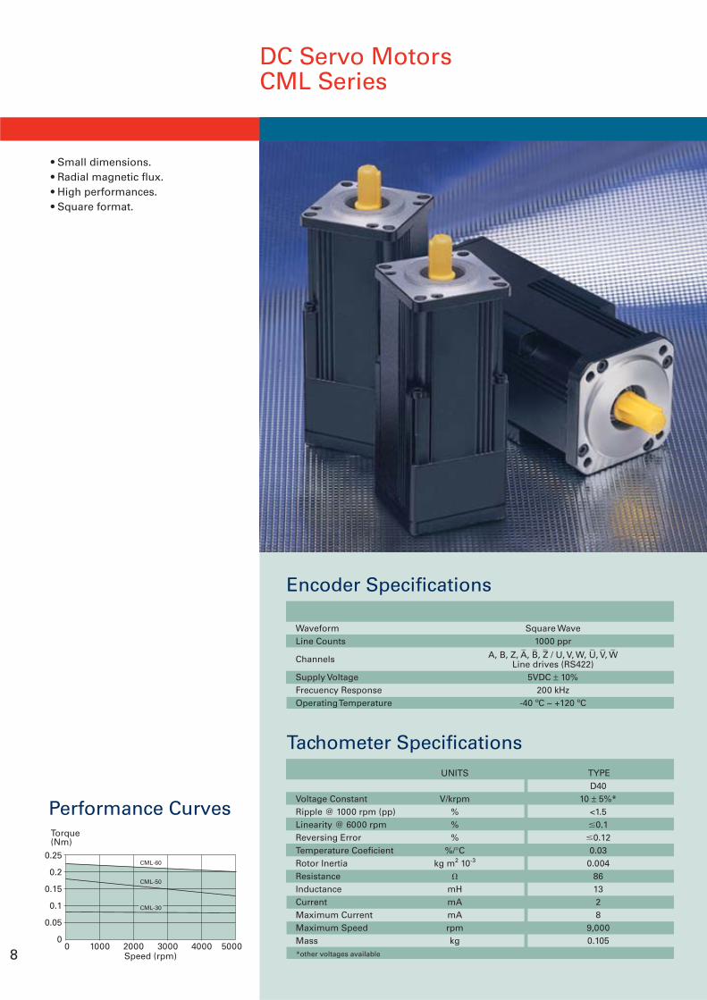
DC Servo MotorsCML Series
• Small dimensions.• Radial magnetic flux.• High performances.• Square format.
Performance Curves
0.25
0.2
0.15
0.1
0.05
00 1000 2000 3000 4000 5000
Speed (rpm)
Torque(Nm)
CML-50
CML-60
CML-30
8
Encoder Specifications
WaveformLine Counts
Channels
Supply VoltageFrecuency ResponseOperating Temperature
Square Wave1000 ppr
A, B, Z, A, B, Z / U, V, W, U, V, WLine drives (RS422)
5VDC ± 10%200 kHz
-40 ºC ~ +120 ºC
_ _ _ _ _ _
Tachometer Specifications
Voltage ConstantRipple @ 1000 rpm (pp)Linearity @ 6000 rpmReversing ErrorTemperature CoeficientRotor InertiaResistanceInductanceCurrentMaximum CurrentMaximum SpeedMass
UNITS
V/krpm%%%
%/°Ckg m2 10-3
mHmAmArpmkg
*other voltages available
D4010 ± 5%*
<1.50.1
0.120.03
0.004861328
9,0000.105
TYPE
9
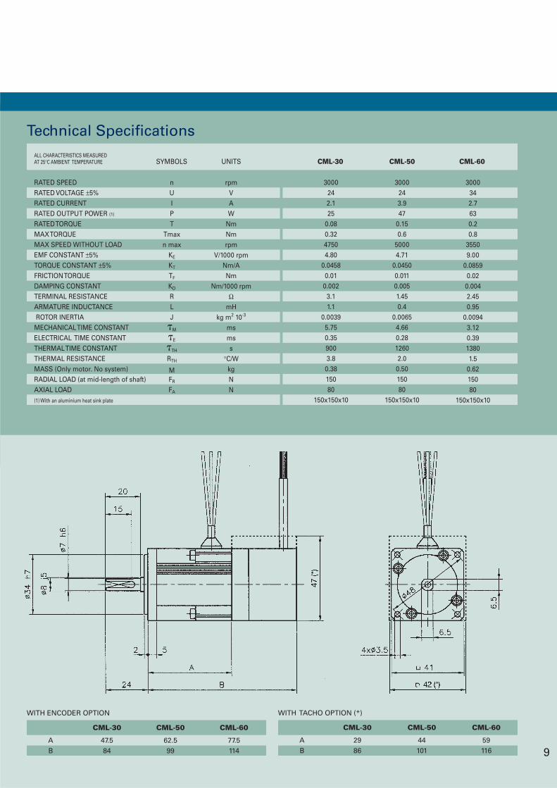
CML-50
62.599
CML-60
77.5114
CML-30
47.584
AB
WITH ENCODER OPTION
CML-50
44101
CML-60
59116
CML-30
2986
AB
WITH TACHO OPTION (*)
Technical SpecificationsALL CHARACTERISTICS MEASUREDAT 25°C AMBIENT TEMPERATURE
rpmVAW
NmNmrpm
V/1000 rpmNm/ANm
Nm/1000 rpmΩ
mHkg m2 10-3
msmss
°C/WkgNN
nUIPT
Tmaxn max
KE
KT
TF
KD
RLJM
E
TH
RTH
MFR
FA
3000242.125
0.080.3247504.80
0.04580.01
0.0023.11.1
0.00395.750.359003.80.3815080
150x150x10
3000342.7630.20.8
35509.00
0.08590.020.0042.450.95
0.00943.120.3913801.5
0.6215080
150x150x10
3000243.947
0.150.6
50004.71
0.04500.0110.0051.450.4
0.00654.660.2812602.00.5015080
150x150x10
RATED SPEEDRATED VOLTAGE ±5%RATED CURRENTRATED OUTPUT POWER (1)
RATED TORQUEMAX TORQUEMAX SPEED WITHOUT LOADEMF CONSTANT ±5%TORQUE CONSTANT ±5%FRICTION TORQUEDAMPING CONSTANTTERMINAL RESISTANCEARMATURE INDUCTANCE ROTOR INERTIAMECHANICAL TIME CONSTANTELECTRICAL TIME CONSTANTTHERMAL TIME CONSTANTTHERMAL RESISTANCEMASS (Only motor. No system)RADIAL LOAD (at mid-length of shaft)AXIAL LOAD(1) With an aluminium heat sink plate
SYMBOLS UNITS CML-30 CML-50 CML-60
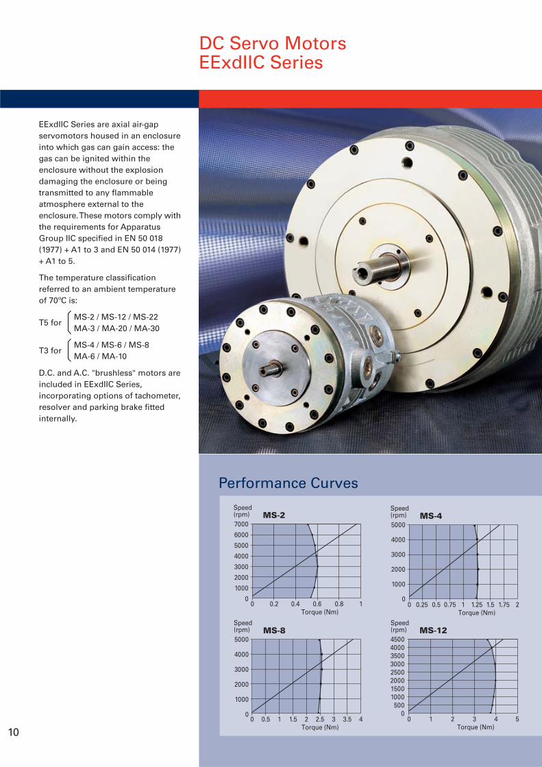
DC Servo MotorsEExdIIC Series
10
EExdIIC Series are axial air-gapservomotors housed in an enclosureinto which gas can gain access: thegas can be ignited within theenclosure without the explosiondamaging the enclosure or beingtransmitted to any flammableatmosphere external to theenclosure. These motors comply withthe requirements for ApparatusGroup IIC specified in EN 50 018(1977) + A1 to 3 and EN 50 014 (1977)+ A1 to 5.
The temperature classificationreferred to an ambient temperatureof 70ºC is:
MS-2 / MS-12 / MS-22MA-3 / MA-20 / MA-30
MS-4 / MS-6 / MS-8MA-6 / MA-10
D.C. and A.C. "brushless" motors areincluded in EExdIIC Series,incorporating options of tachometer,resolver and parking brake fittedinternally.
T5 for
T3 for
Performance Curves
7000
6000
5000
4000
3000
2000
1000
00 0.2 0.4 0.6 0.8 1
Torque (Nm)
MS-2Speed(rpm)
45004000350030002500200015001000500
00 1 2 3 4 5
Torque (Nm)
MS-12Speed(rpm)
5000
4000
3000
2000
1000
00 0.25 0.5 0.75 1 1.25 1.5 1.75 2
Torque (Nm)
MS-4Speed(rpm)
5000
4000
3000
2000
1000
00 0.5 1 1.5 2 2.5 3 3.5 4
Torque (Nm)
MS-8Speed(rpm)
Tachometer Specifications
*other voltages available
Voltage Constant
Ripple @ 1000 rpm (pp)
Linearity @ 6000 rpm
Reversing Error
Temperature Coeficient
Rotor Inertia
Resistance
Inductance
Current
Maximum Current
Maximum Speed
Mass
UNITS
SIZE
V/krpm
%
%
%
%/°C
kg m2 10-3
mH
mA
mA
rpm
kg
MS-2
D40
10 ± 5%*
<1.5
0.1
0.12
0.03
0.004
86
13
2
8
9,000
0.105
MS-22
D26
10 ± 5%*
<1.2
0.1
0.12
0.02
0.024
90
25
4
17
8,000
0.295
MS-4
D40
10 ± 5%*
<1.5
0.1
0.12
0.03
0.004
86
13
2
8
9,000
0.105
MS-6
D40
10 ± 5%*
<1.5
0.1
0.12
0.03
0.004
86
13
2
8
9,000
0.105
MS-8
D40
10 ± 5%*
<1.5
0.1
0.12
0.03
0.004
86
13
2
8
9,000
0.105
MS-12
D40
10 ± 5%*
<1.5
0.1
0.12
0.03
0.004
86
13
2
8
9,000
0.105
11
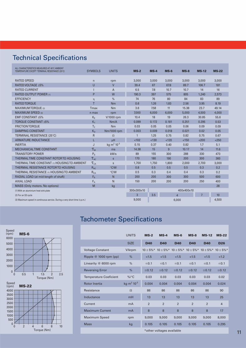
Technical Specifications
RATED SPEEDRATED VOLTAGE ±5%RATED CURRENTRATED OUTPUT POWER (1)
EFFICIENCYRATED TORQUEMAXIMUM TORQUE (2)
MAXIMUM SPEED (3)
EMF CONSTANT ±5%TORQUE CONSTANT ±5%FRICTION TORQUEDAMPING CONSTANTTERMINAL RESISTANCE (25°C)ARMATURE INDUCTANCEINERTIAMECHANICAL TIME CONSTANTTRANSITORY POWERTHERMAL TIME CONSTANT ROTOR TO HOUSINGTHERMAL TIME CONSTANT (1) HOUSING TO AMBIENTTHERMAL RESISTANCE ROTOR TO HOUSINGTHERMAL RESISTANCE (1) HOUSING TO AMBIENTRADIAL LOAD (at mid-length of shaft)AXIAL LOADMASS (Only motors. No options)(1) With an aluminium heat sink plate
(2) For an S3 cycle
(3) Maximum speed in continuous service. During a very short time (r.p.m.)
3,000677.839776
1.267.58
6,00018
0.1720.05
0.0091.25<1300.3715155180
1,7500.50.3200200
3.5
3,00067.810.757580
1.8311
6,00019
0.1810.050.0180.75<1200.40
9300190
1,8000.50.4300200
3,000106.7
141,240
833.9523.7
4,50030.850.2950.090.020.75<2001.714
330300
2,7000.30.3500250
7
3,00018116
2,57389
8.1949.144,00055.60.530.090.050.67<2505.111.6473360
3,0000.20.260040028
104,500
3,00039.46.5
190.3740.63.6
7,00010.4
0.0990.03
0.0031
<1020.1514.38
89170
1,7000.80.5200150
300x300x103
9,000
ALL CHARACTERISTICS MEASURED AT 40°C AMBIENTTEMPERATURE EXCEPT TERMINAL RESISTANCE (25°C)
rpmVAW%
NmNmrpm
V/1000 rpmNm/ANm
Nm/1000 rpm
µHkg m2 10-3
mskW/s
ss
°C/W°C/W
NNkg
nUIP
TTmaxn max
KE
KT
TF
KD
RLJM
PS
AC
CA
RAC
RCA
FR
FA
M
46,000
3,00089.710.780584
2.5615.385,00026.3
0.2510.06
0.0210.82<1500.8210.17288200
2,0000.50.4300200
400x400x10
SYMBOLS UNITS MS-2 MS-4 MS-6 MS-8 MS-12 MS-22
4000350030002500200015001000500
00 2 4 6 8 10
Torque (Nm)
MS-22Speed(rpm)
6000
5000
4000
3000
2000
1000
00 0.5 1 1.5 2 2.5
Torque (Nm)
MS-6Speed(rpm)
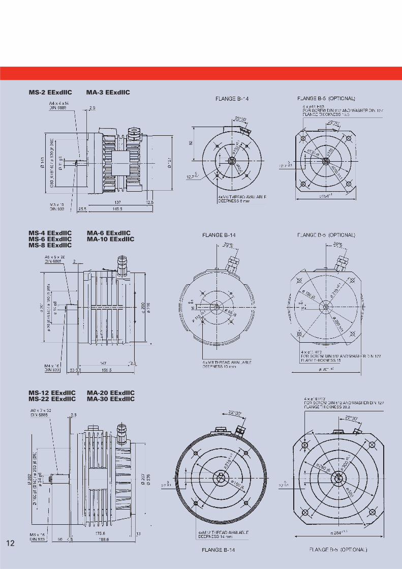
MS-2 EExdIIC MA-3 EExdIIC
MA-20 EExdIICMA-30 EExdIIC
MS-12 EExdIICMS-22 EExdIIC
MA-6 EExdIICMA-10 EExdIIC
MS-4 EExdIICMS-6 EExdIICMS-8 EExdIIC
12
AC Servo MotorsEExdIIC Series
Resolver SpecificationsUNITS
V/kHz
minutes
VAC/1 minute
kg
kg m2 10-3
°C
10/4.5
Rotor
1X
0.5 ± 5%
±10 max.
500
0.230
0.0123
-55 ~ +155
2T8(Transmitter Speed 1)
Input Voltage/Frecuency
Primary Element
Number of Speed
Transformation Ratio
Electrical Error
Dielectric Strength
Mass
Rotor Moment of Inertia
Operating Temperature Range
13
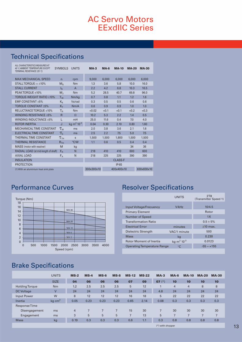
Technical SpecificationsALL CHARACTERISTICS MEASURED AT40° C AMBIENT TEMPERATURE EXCEPTTERMINAL RESISTANCE (25° C)
MAX MECHANICAL SPEEDSTALL TORQUE (1) ±10%STALL CURRENTPEAK TORQUE ±10%TORQUE-WEIGHT RATIO ±10%EMF CONSTANT ±5%TORQUE CONSTANT ±5%RELUCTANCE TORQUE ±10%WINDING RESISTANCE ±5%WINDING INDUCTANCE ±5%ROTOR INERTIAMECHANICAL TIME CONSTANTELECTRICAL TIME CONSTANTTHERMAL TIME CONSTANTTHERMAL RESISTANCEMASS (motor with resolver)RADIAL LOAD (at mid-length of shaft)AXIAL LOADINSULATIONPROTECTION(1) With an aluminium heat sink plate
nMS
ISMJ
TW
KE
KT
TR
RLJM
E
TH
RTH
MFR
FA
rpmNmA
NmNm/kgVs/radNm/ANm
mHkg m2 10-3
msmss
ºC/WkgNN
9,0001.32.25.20.70.30.6
<0.0210.225.00.042.02.5
1,5001.1
218218
300x300x10
6,0003.64.228.50.80.50.9
<0.15.311.60.303.82.2
1,5000.6
410225
6,0005.86.8
40.71.10.50.9
<0.12.20.42.103.67.5
1,8000.5
410225
CLASS-FIP-65
400x400x10
6,00010.010.369.81.20.61.0
<0.21.47.0
0.802.15.0
1,5000.434
600390
6,00016.016.596.01.60.61.0
<0.30.54.01.601.67.5
1,5000.436
600390
830x830x10
SYMBOLS UNITS MA-3 MA-6 MA-10 MA-20 MA-30
Holding Torque
DC Voltage
Input Power
Inertia
Response Time
Disengagement
Engagement
Mass
UNITS
(*) with chopper
Brake Specifications
SIZE
Nm
V
W
kg cm2
ms
ms
kg
MS-2
04
1.2
24
8
0.05
4
3
0.19
MS-4
06
2.5
24
12
0.23
7
5
0.3
MS-12
07
5
24
16
0.65
15
7
0.6
MA-20
10
8
24
22
0.3
30
7
0.8
MA-3
07 (*)
1
4.8
5
0.08
7
5
0.3
MS-22
09
12
24
18
2.14
30
13
1.1
MA-6
10
4
24
22
0.3
30
7
0.8
MA-30
10
8
24
22
0.3
30
7
0.8
MA-10
10
4
24
22
0.3
30
7
0.8
MS-6
06
2.5
24
12
0.23
7
5
0.3
MS-8
06
2.5
24
12
0.23
7
5
0.3
Performance Curves
181614121086420
0 500 1000 1500 2000 2500 3000 3500 4000Speed (rpm)
Torque (Nm)
MA-30
MA-20
MA-3
MA-6
MA-10
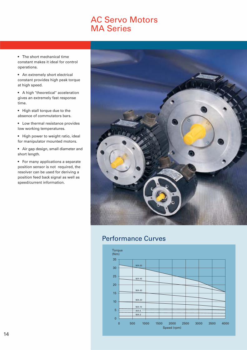
• The short mechanical timeconstant makes it ideal for controloperations.
• An extremely short electricalconstant provides high peak torqueat high speed.
• A high "theoretical" accelerationgives an extremely fast responsetime.
• High stall torque due to theabsence of commutators bars.
• Low thermal resistance provideslow working temperatures.
• High power to weight ratio, idealfor manipulator mounted motors.
• Air gap design, small diameter andshort length.
• For many applications a separateposition sensor is not required, theresolver can be used for deriving aposition feed back signal as well asspeed/current information.
AC Servo MotorsMA Series
14
Performance Curves
35
30
25
20
15
10
5
0
0 500 1000 1500 2000 2500 3000 3500 4000Speed (rpm)
Torque(Nm)
MA-55
MA-45
MA-30
MA-20
MA-10
MA-3
MA-6
15
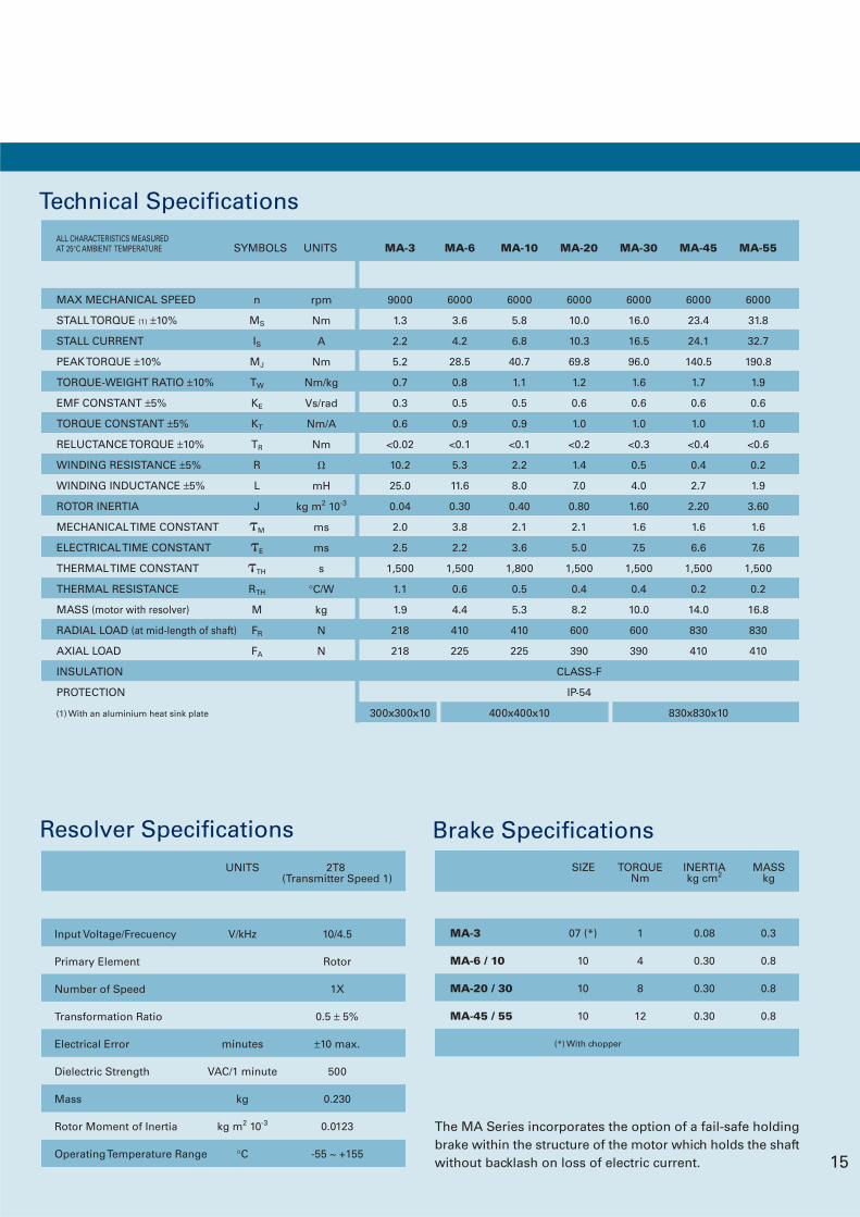
ALL CHARACTERISTICS MEASUREDAT 25°C AMBIENT TEMPERATURE
Technical Specifications
MAX MECHANICAL SPEED
STALL TORQUE (1) ±10%
STALL CURRENT
PEAK TORQUE ±10%
TORQUE-WEIGHT RATIO ±10%
EMF CONSTANT ±5%
TORQUE CONSTANT ±5%
RELUCTANCE TORQUE ±10%
WINDING RESISTANCE ±5%
WINDING INDUCTANCE ±5%
ROTOR INERTIA
MECHANICAL TIME CONSTANT
ELECTRICAL TIME CONSTANT
THERMAL TIME CONSTANT
THERMAL RESISTANCE
MASS (motor with resolver)
RADIAL LOAD (at mid-length of shaft)
AXIAL LOAD
INSULATION
PROTECTION
(1) With an aluminium heat sink plate
6000
10.0
10.3
69.8
1.2
0.6
1.0
<0.2
1.4
7.0
0.80
2.1
5.0
1,500
0.4
8.2
600
390
CLASS-F
IP-54
6000
16.0
16.5
96.0
1.6
0.6
1.0
<0.3
0.5
4.0
1.60
1.6
7.5
1,500
0.4
10.0
600
390
6000
23.4
24.1
140.5
1.7
0.6
1.0
<0.4
0.4
2.7
2.20
1.6
6.6
1,500
0.2
14.0
830
410
830x830x10
6000
31.8
32.7
190.8
1.9
0.6
1.0
<0.6
0.2
1.9
3.60
1.6
7.6
1,500
0.2
16.8
830
410
9000
1.3
2.2
5.2
0.7
0.3
0.6
<0.02
10.2
25.0
0.04
2.0
2.5
1,500
1.1
1.9
218
218
300x300x10
6000
5.8
6.8
40.7
1.1
0.5
0.9
<0.1
2.2
8.0
0.40
2.1
3.6
1,800
0.5
5.3
410
225
400x400x10
n
MS
IS
MJ
TW
KE
KT
TR
R
L
J
M
E
TH
RTH
M
FR
FA
rpm
Nm
A
Nm
Nm/kg
Vs/rad
Nm/A
Nm
mH
kg m2 10-3
ms
ms
s
°C/W
kg
N
N
6000
3.6
4.2
28.5
0.8
0.5
0.9
<0.1
5.3
11.6
0.30
3.8
2.2
1,500
0.6
4.4
410
225
SYMBOLS UNITS MA-3 MA-6 MA-10 MA-20 MA-30 MA-45 MA-55
The MA Series incorporates the option of a fail-safe holdingbrake within the structure of the motor which holds the shaftwithout backlash on loss of electric current.
Brake Specifications
MA-3
MA-6 / 10
MA-20 / 30
MA-45 / 55
07 (*)
10
10
10
0.3
0.8
0.8
0.8
1
4
8
12
0.08
0.30
0.30
0.30
MASSkg
TORQUENm
INERTIAkg cm2
SIZE
(*) With chopper
Resolver Specifications2T8
(Transmitter Speed 1)
Input Voltage/Frecuency
Primary Element
Number of Speed
Transformation Ratio
Electrical Error
Dielectric Strength
Mass
Rotor Moment of Inertia
Operating Temperature Range
UNITS
V/kHz
minutes
VAC/1 minute
kg
kg m2 10-3
°C
10/4.5
Rotor
1X
0.5 ± 5%
±10 max.
500
0.230
0.0123
-55 ~ +155
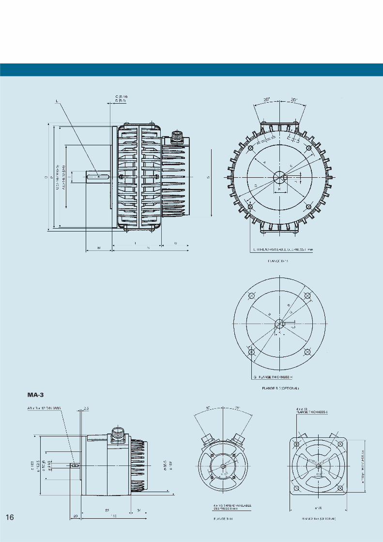
MA-3
16
AC Servo MotorsMA Series
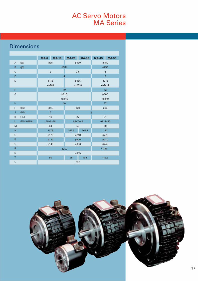
17
MA-20 MA-30
ø130
3.5
ø165
4xM10
ø24
27
A8x7x45
50
152.5 161.5
ø218
ø210
ø186
ø165
95 104
57.5
MA-6 MA-10
ø95
3
ø115
4xM8
ø14
5
16
A5x5x28
34
137.5
ø178
ø170
ø140
80
8
ø180
4
10
ø215
4xø15
10
ø250
A (j6)
B (j6)
C
D
E
F
G
H
I (k6)
J (N9)
K ( )
L (DIN 6885)
M
N
O
P
Q
R
S
T
U
MA-45 MA-55
ø180
ø250
4
5
ø215
4xM12
12
ø300
4xø19
17
ø28
31
A8x7x50
60
174
ø278
ø270
ø242
265
116.5
0-0.1
Dimensions
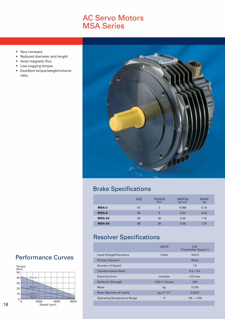
• Very compact.• Reduced diameter and length.• Axial magnetic flux.• Low cogging torque.• Excellent torque/weight/volume
ratio.
Brake Specifications
Performance Curves
50
40
30
20
10
00 3000 6000 9000
Speed (rpm)
Torque(Nm)
MSA-02
MSA-08
MSA-22
MSA-45
18
AC Servo MotorsMSA Series
Resolver Specifications2T8
(Transmitter Speed 1)UNITS
V/kHz
minutes
VAC/1 minute
kg
kg m2 10-3
°C
10/4.5
Rotor
1X
0.5 ± 5%
±10 max.
500
0.230
0.0123
-55 ~ +155
Input Voltage/Frecuency
Primary Element
Number of Speed
Transformation Ratio
Electrical Error
Dielectric Strength
Mass
Rotor Moment of Inertia
Operating Temperature Range
MASSkg
TORQUENm
INERTIAkg cm2
SIZE
MSA-2
MSA-8
MSA-22
MSA-45
03
06
08
08
0.18
0.50
1.75
1.75
2
9
36
36
0.068
0.54
5.56
5.56
19
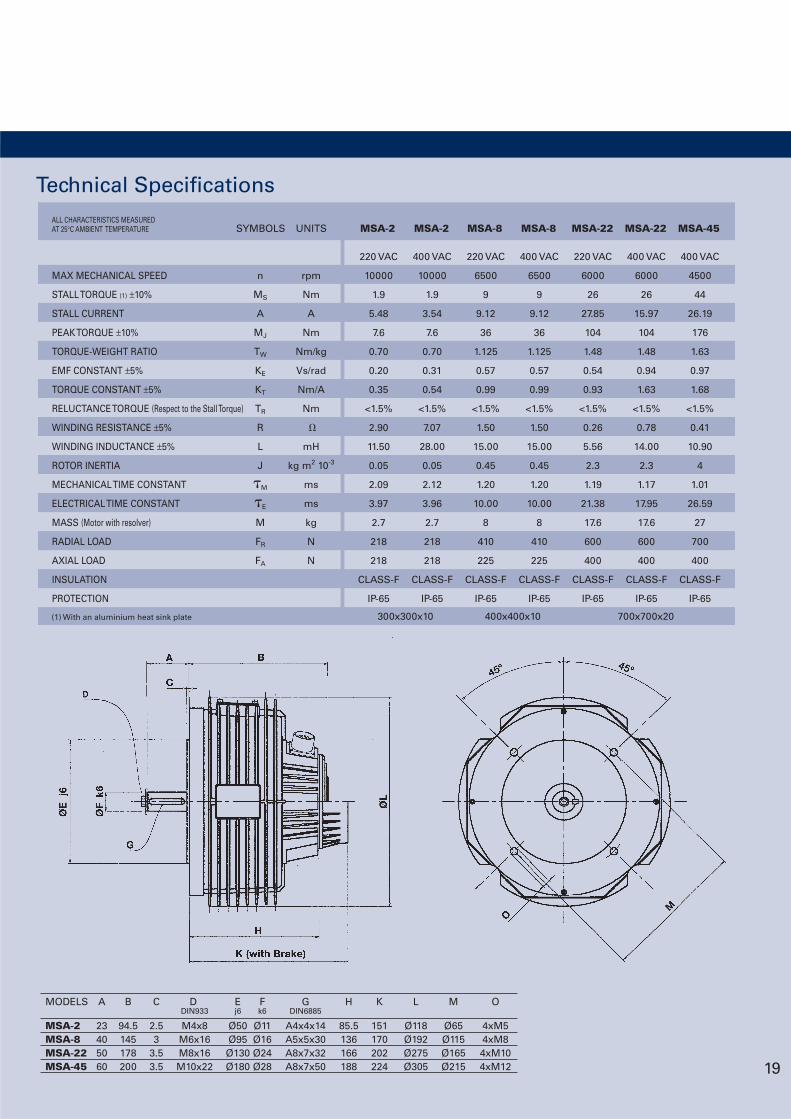
MODELS A B C D E F G H K L M ODIN933 j6 k6 DIN6885
MSA-2 23 94.5 2.5 M4x8 Ø50 Ø11 A4x4x14 85.5 151 Ø118 Ø65 4xM5MSA-8 40 145 3 M6x16 Ø95 Ø16 A5x5x30 136 170 Ø192 Ø115 4xM8MSA-22 50 178 3.5 M8x16 Ø130 Ø24 A8x7x32 166 202 Ø275 Ø165 4xM10MSA-45 60 200 3.5 M10x22 Ø180 Ø28 A8x7x50 188 224 Ø305 Ø215 4xM12
Technical SpecificationsALL CHARACTERISTICS MEASUREDAT 25°C AMBIENT TEMPERATURE
MAX MECHANICAL SPEED
STALL TORQUE (1) ±10%
STALL CURRENT
PEAK TORQUE ±10%
TORQUE-WEIGHT RATIO
EMF CONSTANT ±5%
TORQUE CONSTANT ±5%
RELUCTANCE TORQUE (Respect to the Stall Torque)
WINDING RESISTANCE ±5%
WINDING INDUCTANCE ±5%
ROTOR INERTIA
MECHANICAL TIME CONSTANT
ELECTRICAL TIME CONSTANT
MASS (Motor with resolver)
RADIAL LOAD
AXIAL LOAD
INSULATION
PROTECTION
400 VAC
6500
9
9.12
36
1.125
0.57
0.99
<1.5%
1.50
15.00
0.45
1.20
10.00
8
410
225
CLASS-F
IP-65
220 VAC
6000
26
27.85
104
1.48
0.54
0.93
<1.5%
0.26
5.56
2.3
1.19
21.38
17.6
600
400
CLASS-F
IP-65
400 VAC
6000
26
15.97
104
1.48
0.94
1.63
<1.5%
0.78
14.00
2.3
1.17
17.95
17.6
600
400
CLASS-F
IP-65
400 VAC
4500
44
26.19
176
1.63
0.97
1.68
<1.5%
0.41
10.90
4
1.01
26.59
27
700
400
CLASS-F
IP-65
220 VAC
10000
1.9
5.48
7.6
0.70
0.20
0.35
<1.5%
2.90
11.50
0.05
2.09
3.97
2.7
218
218
CLASS-F
IP-65
220 VAC
6500
9
9.12
36
1.125
0.57
0.99
<1.5%
1.50
15.00
0.45
1.20
10.00
8
410
225
CLASS-F
IP-65
n
MS
A
MJ
TW
KE
KT
TR
R
L
J
M
E
M
FR
FA
rpm
Nm
A
Nm
Nm/kg
Vs/rad
Nm/A
Nm
mH
kg m2 10-3
ms
ms
kg
N
N
400 VAC
10000
1.9
3.54
7.6
0.70
0.31
0.54
<1.5%
7.07
28.00
0.05
2.12
3.96
2.7
218
218
CLASS-F
IP-65
SYMBOLS UNITS MSA-2 MSA-2 MSA-8 MSA-8 MSA-22 MSA-22 MSA-45
(1) With an aluminium heat sink plate 300x300x10 400x400x10 700x700x20
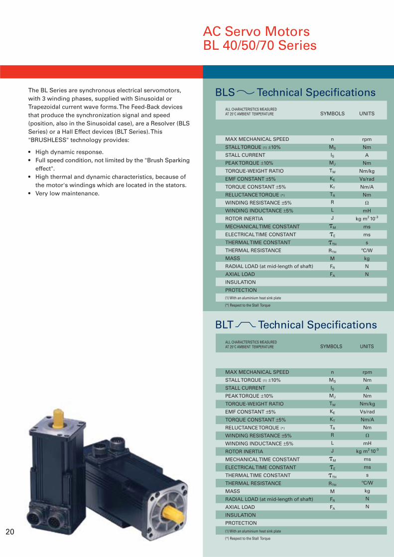
AC Servo MotorsBL 40/50/70 Series
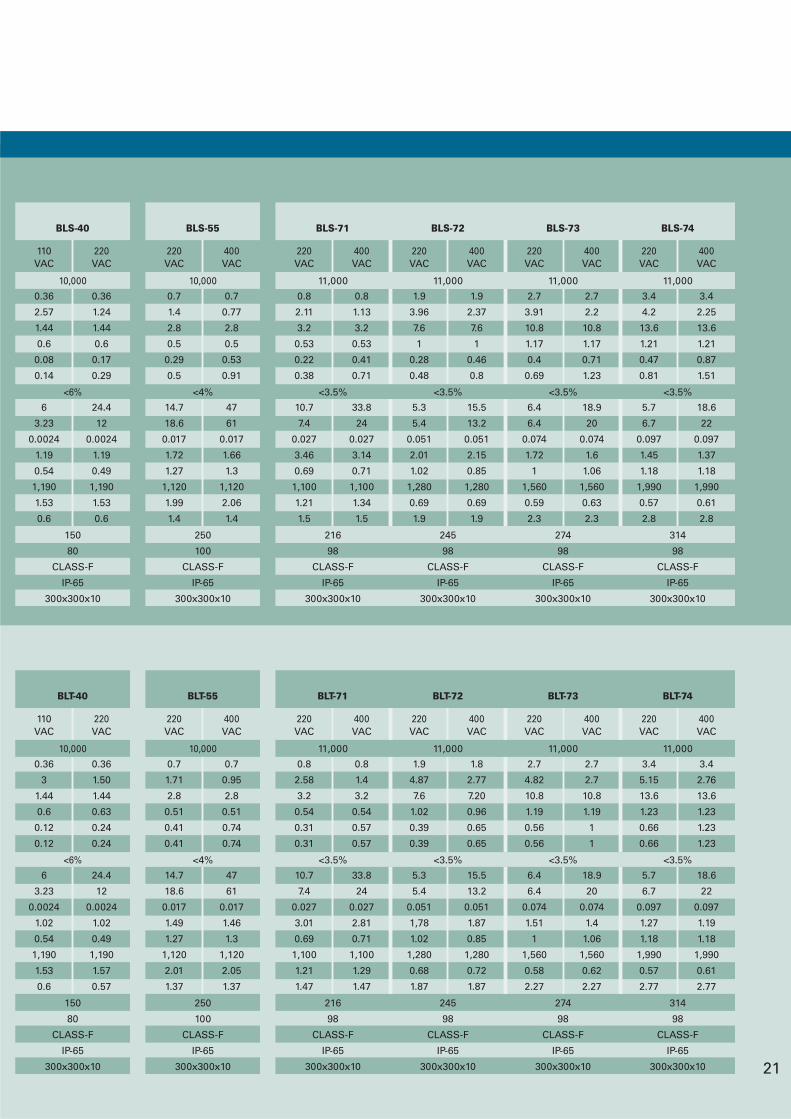
The BL Series are synchronous electrical servomotors,with 3 winding phases, supplied with Sinusoidal orTrapezoidal current wave forms. The Feed-Back devicesthat produce the synchronization signal and speed(position, also in the Sinusoidal case), are a Resolver (BLSSeries) or a Hall Effect devices (BLT Series). This"BRUSHLESS" technology provides:
• High dynamic response.• Full speed condition, not limited by the "Brush Sparking
effect".• High thermal and dynamic characteristics, because of
the motor's windings which are located in the stators.• Very low maintenance.
20
MAX MECHANICAL SPEED
STALL TORQUE (1) ±10%
STALL CURRENT
PEAK TORQUE ±10%
TORQUE-WEIGHT RATIO
EMF CONSTANT ±5%
TORQUE CONSTANT ±5%
RELUCTANCE TORQUE (*)
WINDING RESISTANCE ±5%
WINDING INDUCTANCE ±5%
ROTOR INERTIA
MECHANICAL TIME CONSTANT
ELECTRICAL TIME CONSTANT
THERMAL TIME CONSTANT
THERMAL RESISTANCE
MASS
RADIAL LOAD (at mid-length of shaft)
AXIAL LOAD
INSULATION
PROTECTION
ALL CHARACTERISTICS MEASUREDAT 25°C AMBIENT TEMPERATURE
n
MS
ISMJ
TW
KE
KT
TR
R
L
J
M
E
TH
RTH
M
FR
FA
rpm
Nm
A
Nm
Nm/kg
Vs/rad
Nm/A
Nm
mH
kg m2 10-3
ms
ms
s
ºC/W
kg
N
N
BLS Technical Specifications
(1) With an aluminium heat sink plate
(*) Respect to the Stall Torque
SYMBOLS UNITS
MAX MECHANICAL SPEED
STALL TORQUE (1) ±10%
STALL CURRENT
PEAK TORQUE ±10%
TORQUE-WEIGHT RATIO
EMF CONSTANT ±5%
TORQUE CONSTANT ±5%
RELUCTANCE TORQUE (*)
WINDING RESISTANCE ±5%
WINDING INDUCTANCE ±5%
ROTOR INERTIA
MECHANICAL TIME CONSTANT
ELECTRICAL TIME CONSTANT
THERMAL TIME CONSTANT
THERMAL RESISTANCE
MASS
RADIAL LOAD (at mid-length of shaft)
AXIAL LOAD
INSULATION
PROTECTION
ALL CHARACTERISTICS MEASUREDAT 25°C AMBIENT TEMPERATURE
n
MS
ISMJ
TW
KE
KT
TR
R
L
J
M
E
TH
RTH
M
FR
FA
rpm
Nm
A
Nm
Nm/kg
Vs/rad
Nm/A
Nm
mH
kg m2 10-3
ms
ms
s
ºC/W
kg
N
N
BLT Technical Specifications
(1) With an aluminium heat sink plate
(*) Respect to the Stall Torque
SYMBOLS UNITS
21
220VAC
0.8
2.11
3.2
0.53
0.22
0.38
10.7
7.4
0.027
3.46
0.69
1,100
1.21
1.5
400VAC
0.8
1.13
3.2
0.53
0.41
0.71
33.8
24
0.027
3.14
0.71
1,100
1.34
1.5
11,000
<3.5%
216
98
CLASS-F
IP-65
300x300x10
220VAC
1.9
3.96
7.6
1
0.28
0.48
5.3
5.4
0.051
2.01
1.02
1,280
0.69
1.9
400VAC
1.9
2.37
7.6
1
0.46
0.8
15.5
13.2
0.051
2.15
0.85
1,280
0.69
1.9
11,000
<3.5%
245
98
CLASS-F
IP-65
300x300x10
220VAC
2.7
3.91
10.8
1.17
0.4
0.69
6.4
6.4
0.074
1.72
1
1,560
0.59
2.3
400VAC
2.7
2.2
10.8
1.17
0.71
1.23
18.9
20
0.074
1.6
1.06
1,560
0.63
2.3
11,000
<3.5%
274
98
CLASS-F
IP-65
300x300x10
220VAC
3.4
4.2
13.6
1.21
0.47
0.81
5.7
6.7
0.097
1.45
1.18
1,990
0.57
2.8
400VAC
3.4
2.25
13.6
1.21
0.87
1.51
18.6
22
0.097
1.37
1.18
1,990
0.61
2.8
11,000
<3.5%
314
98
CLASS-F
IP-65
300x300x10
110VAC
0.36
2.57
1.44
0.6
0.08
0.14
6
3.23
0.0024
1.19
0.54
1,190
1.53
0.6
220VAC
0.36
1.24
1.44
0.6
0.17
0.29
24.4
12
0.0024
1.19
0.49
1,190
1.53
0.6
10,000
<6%
150
80
CLASS-F
IP-65
300x300x10
220VAC
0.7
1.4
2.8
0.5
0.29
0.5
14.7
18.6
0.017
1.72
1.27
1,120
1.99
1.4
400VAC
0.7
0.77
2.8
0.5
0.53
0.91
47
61
0.017
1.66
1.3
1,120
2.06
1.4
10,000
<4%
250
100
CLASS-F
IP-65
300x300x10
BLS-40 BLS-55 BLS-71 BLS-72 BLS-73 BLS-74
220VAC
0.8
2.58
3.2
0.54
0.31
0.31
10.7
7.4
0.027
3.01
0.69
1,100
1.21
1.47
400VAC
0.8
1.4
3.2
0.54
0.57
0.57
33.8
24
0.027
2.81
0.71
1,100
1.29
1.47
11,000
<3.5%
216
98
CLASS-F
IP-65
300x300x10
220VAC
1.9
4.87
7.6
1.02
0.39
0.39
5.3
5.4
0.051
1,78
1.02
1,280
0.68
1.87
400VAC
1.8
2.77
7.20
0.96
0.65
0.65
15.5
13.2
0.051
1.87
0.85
1,280
0.72
1.87
11,000
<3.5%
245
98
CLASS-F
IP-65
300x300x10
220VAC
2.7
4.82
10.8
1.19
0.56
0.56
6.4
6.4
0.074
1.51
1
1,560
0.58
2.27
400VAC
2.7
2.7
10.8
1.19
1
1
18.9
20
0.074
1.4
1.06
1,560
0.62
2.27
11,000
<3.5%
274
98
CLASS-F
IP-65
300x300x10
220VAC
3.4
5.15
13.6
1.23
0.66
0.66
5.7
6.7
0.097
1.27
1.18
1,990
0.57
2.77
400VAC
3.4
2.76
13.6
1.23
1.23
1.23
18.6
22
0.097
1.19
1.18
1,990
0.61
2.77
11,000
<3.5%
314
98
CLASS-F
IP-65
300x300x10
110VAC
0.36
3
1.44
0.6
0.12
0.12
6
3.23
0.0024
1.02
0.54
1,190
1.53
0.6
220VAC
0.36
1.50
1.44
0.63
0.24
0.24
24.4
12
0.0024
1.02
0.49
1,190
1.57
0.57
10,000
<6%
150
80
CLASS-F
IP-65
300x300x10
220VAC
0.7
1.71
2.8
0.51
0.41
0.41
14.7
18.6
0.017
1.49
1.27
1,120
2.01
1.37
400VAC
0.7
0.95
2.8
0.51
0.74
0.74
47
61
0.017
1.46
1.3
1,120
2.05
1.37
10,000
<4%
250
100
CLASS-F
IP-65
300x300x10
BLT-40 BLT-55 BLT-71 BLT-72 BLT-73 BLT-74
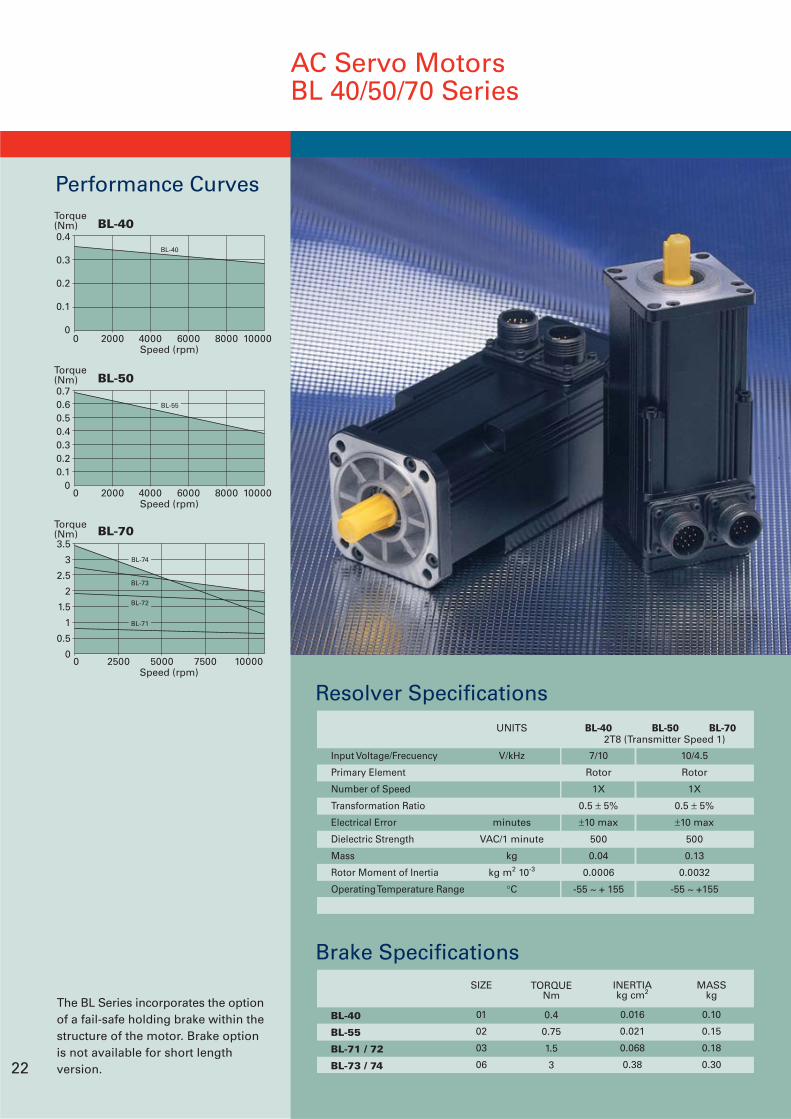
AC Servo MotorsBL 40/50/70 Series
The BL Series incorporates the optionof a fail-safe holding brake within thestructure of the motor. Brake optionis not available for short lengthversion.
Brake Specifications
BL-40
BL-55
BL-71 / 72
BL-73 / 74
SIZE
01
02
03
06
TORQUENm
0.4
0.75
1.5
3
INERTIAkg cm2
0.016
0.021
0.068
0.38
MASSkg
0.10
0.15
0.18
0.30
Performance Curves
0.70.60.50.40.30.20.1
00 2000 4000 6000 8000 10000
Speed (rpm)
BL-50Torque(Nm)
BL-55
0.4
0.3
0.2
0.1
00 2000 4000 6000 8000 10000
Speed (rpm)
BL-40Torque(Nm)
BL-40
Resolver Specifications
Input Voltage/Frecuency
Primary Element
Number of Speed
Transformation Ratio
Electrical Error
Dielectric Strength
Mass
Rotor Moment of Inertia
Operating Temperature Range
UNITS
V/kHz
minutes
VAC/1 minute
kg
kg m2 10-3
°C
BL-40
7/10
Rotor
1X
0.5 ± 5%
±10 max
500
0.04
0.0006
-55 ~ + 155
BL-70BL-502T8 (Transmitter Speed 1)
10/4.5
Rotor
1X
0.5 ± 5%
±10 max
500
0.13
0.0032
-55 ~ +155
22
0 2500 5000 7500 10000
3.5
3
2.5
2
1.5
1
0.5
0
Speed (rpm)
BL-70Torque(Nm)
BL-73
BL-74
BL-72
BL-71
BL-72
96.5
120.5
BL-73
114.5
138.5
BL-74
132.5
156.5
BL-71
76.5
100.5
A
B
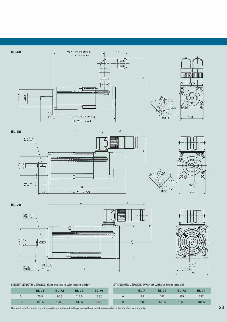
SHORT LENGTH VERSION (Not available with brake option)
BL-72
101
148.5
BL-73
119
166.5
BL-74
137
184.5
BL-71
81
128.5
A
B
STANDARD VERSION (With or without brake option)
23The short length version must be specifically indicated in the order, as the product code applies to the standard version only.
BL-40
BL-50
BL-70
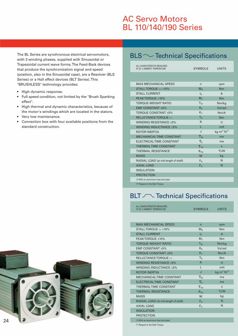
The BL Series are synchronous electrical servomotors,with 3 winding phases, supplied with Sinusoidal orTrapezoidal current wave forms. The Feed-Back devicesthat produce the synchronization signal and speed(position, also in the Sinusoidal case), are a Resolver (BLSSeries) or a Hall effect devices (BLT Series). This"BRUSHLESS" technology provides:
• High dynamic response.• Full speed condition, not limited by the "Brush Sparking
effect".• High thermal and dynamic characteristics, because of
the motor's windings which are located in the stators.• Very low maintenance.• Connection box with four available positions from the
standard construction.
AC Servo MotorsBL 110/140/190 Series
24
MAX MECHANICAL SPEED
STALL TORQUE (1) ±10%
STALL CURRENT
PEAK TORQUE ±10%
TORQUE-WEIGHT RATIO
EMF CONSTANT ±5%
TORQUE CONSTANT ±5%
RELUCTANCE TORQUE (*)
WINDING RESISTANCE ±5%
WINDING INDUCTANCE ±5%
ROTOR INERTIA
MECHANICAL TIME CONSTANT
ELECTRICAL TIME CONSTANT
THERMAL TIME CONSTANT
THERMAL RESISTANCE
MASS
RADIAL LOAD (at mid-length of shaft)
AXIAL LOAD
INSULATION
PROTECTION(1) With an aluminium heat sink plate
(*) Respect to the Stall Torque
ALL CHARACTERISTICS MEASUREDAT 25° C AMBIENT TEMPERATURE
n
MS
ISMJ
TW
KE
KT
TR
R
L
J
M
E
TH
RTH
M
FR
FA
rpm
Nm
A
Nm
Nm/kg
Vs/rad
Nm/A
Nm
mH
kg m2 10-3
ms
ms
s
ºC/W
kg
N
N
BLS Technical Specifications
SYMBOLS UNITS
MAX MECHANICAL SPEED
STALL TORQUE (1) ±10%
STALL CURRENT
PEAK TORQUE ±10%
TORQUE-WEIGHT RATIO
EMF CONSTANT ±5%
TORQUE CONSTANT ±5%
RELUCTANCE TORQUE (*)
WINDING RESISTANCE ±5%
WINDING INDUCTANCE ±5%
ROTOR INERTIA
MECHANICAL TIME CONSTANT
ELECTRICAL TIME CONSTANT
THERMAL TIME CONSTANT
THERMAL RESISTANCE
MASS
RADIAL LOAD (at mid-length of shaft)
AXIAL LOAD
INSULATION
PROTECTION
(1) With an aluminium heat sink plate
(*) Respect to the Stall Torque
ALL CHARACTERISTICS MEASUREDAT 25° C AMBIENT TEMPERATURE
n
MS
ISMJ
TW
KE
KT
TR
R
L
J
M
E
TH
RTH
M
FR
FA
rpm
Nm
A
Nm
Nm/kg
Vs/rad
Nm/A
Nm
mH
kg m2 10-3
ms
ms
s
ºC/W
kg
N
N
BLT Technical Specifications
SYMBOLS UNITS
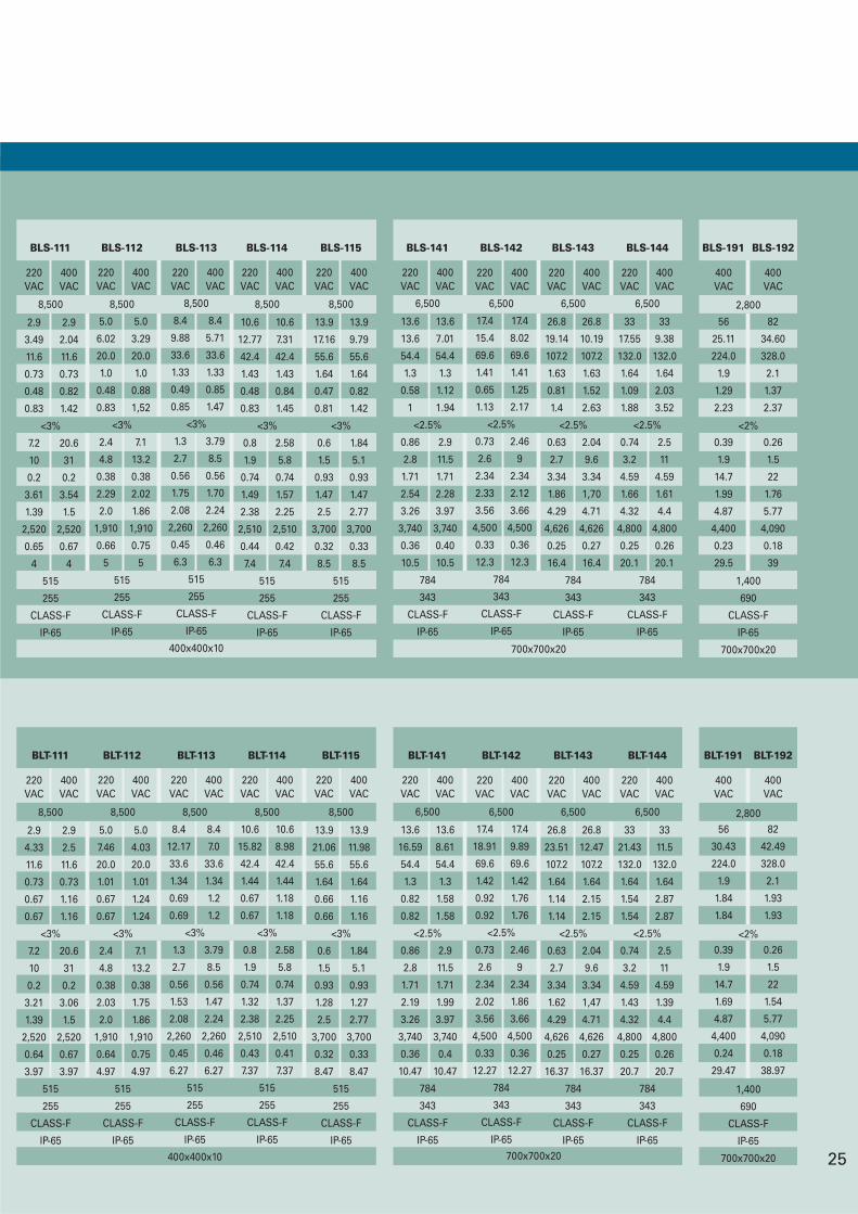
25
220 400VAC VAC
8,500
5.0 5.0
6.02 3.29
20.0 20.0
1.0 1.0
0.48 0.88
0.83 1,52
<3%
2.4 7.1
4.8 13.2
0.38 0.38
2.29 2.02
2.0 1.86
1,910 1,910
0.66 0.75
5 5
515
255
CLASS-F
IP-65
220 400VAC VAC
8,500
10.6 10.6
12.77 7.31
42.4 42.4
1.43 1.43
0.48 0.84
0.83 1.45
<3%
0.8 2.58
1.9 5.8
0.74 0.74
1.49 1.57
2.38 2.25
2,510 2,510
0.44 0.42
7.4 7.4
515
255
CLASS-F
IP-65
220 400VAC VAC
8,500
2.9 2.9
3.49 2.04
11.6 11.6
0.73 0.73
0.48 0.82
0.83 1.42
<3%
7.2 20.6
10 31
0.2 0.2
3.61 3.54
1.39 1.5
2,520 2,520
0.65 0.67
4 4
515
255
CLASS-F
IP-65
220 400VAC VAC
8,500
13.9 13.9
17.16 9.79
55.6 55.6
1.64 1.64
0.47 0.82
0.81 1.42
<3%
0.6 1.84
1.5 5.1
0.93 0.93
1.47 1.47
2.5 2.77
3,700 3,700
0.32 0.33
8.5 8.5
515
255
CLASS-F
IP-65
220 400VAC VAC
8,500
8.4 8.4
9.88 5.71
33.6 33.6
1.33 1.33
0.49 0.85
0.85 1.47
<3%
1.3 3.79
2.7 8.5
0.56 0.56
1.75 1.70
2.08 2.24
2,260 2,260
0.45 0.46
6.3 6.3
515
255
CLASS-F
IP-65
400x400x10
220 400VAC VAC
6,500
13.6 13.6
13.6 7.01
54.4 54.4
1.3 1.3
0.58 1.12
1 1.94
<2.5%
0.86 2.9
2.8 11.5
1.71 1.71
2.54 2.28
3.26 3.97
3,740 3,740
0.36 0.40
10.5 10.5
784
343
CLASS-F
IP-65
220 400VAC VAC
6,500
17.4 17.4
15.4 8.02
69.6 69.6
1.41 1.41
0.65 1.25
1.13 2.17
<2.5%
0.73 2.46
2.6 9
2.34 2.34
2.33 2.12
3.56 3.66
4,500 4,500
0.33 0.36
12.3 12.3
784
343
CLASS-F
IP-65
220 400VAC VAC
6,500
26.8 26.8
19.14 10.19
107.2 107.2
1.63 1.63
0.81 1.52
1.4 2.63
<2.5%
0.63 2.04
2.7 9.6
3.34 3.34
1.86 1,70
4.29 4.71
4,626 4,626
0.25 0.27
16.4 16.4
784
343
CLASS-F
IP-65
220 400VAC VAC
6,500
33 33
17.55 9.38
132.0 132.0
1.64 1.64
1.09 2.03
1.88 3.52
<2.5%
0.74 2.5
3.2 11
4.59 4.59
1.66 1.61
4.32 4.4
4,800 4,800
0.25 0.26
20.1 20.1
784
343
CLASS-F
IP-65
700x700x20
400VAC
56
25.11
224.0
1.9
1.29
2.23
0.39
1.9
14.7
1.99
4.87
4,400
0.23
29.5
400VAC
82
34.60
328.0
2.1
1.37
2.37
0.26
1.5
22
1.76
5.77
4,090
0.18
39
2,800
<2%
1,400
690
CLASS-F
IP-65
700x700x20
BLS-111 BLS-112 BLS-113 BLS-114 BLS-115 BLS-141 BLS-142 BLS-143 BLS-144 BLS-191 BLS-192
400VAC
56
30.43
224.0
1.9
1.84
1.84
0.39
1.9
14.7
1.69
4.87
4,400
0.24
29.47
400VAC
82
42.49
328.0
2.1
1.93
1.93
0.26
1.5
22
1.54
5.77
4,090
0.18
38.97
2,800
<2%
1,400
690
CLASS-F
IP-65
700x700x20
220 400VAC VAC
6,500
13.6 13.6
16.59 8.61
54.4 54.4
1.3 1.3
0.82 1.58
0.82 1.58
<2.5%
0.86 2.9
2.8 11.5
1.71 1.71
2.19 1.99
3.26 3.97
3,740 3,740
0.36 0.4
10.47 10.47
784
343
CLASS-F
IP-65
220 400VAC VAC
6,500
17.4 17.4
18.91 9.89
69.6 69.6
1.42 1.42
0.92 1.76
0.92 1.76
<2.5%
0.73 2.46
2.6 9
2.34 2.34
2.02 1.86
3.56 3.66
4,500 4,500
0.33 0.36
12.27 12.27
784
343
CLASS-F
IP-65
220 400VAC VAC
6,500
26.8 26.8
23.51 12.47
107.2 107.2
1.64 1.64
1.14 2.15
1.14 2.15
<2.5%
0.63 2.04
2.7 9.6
3.34 3.34
1.62 1,47
4.29 4.71
4,626 4,626
0.25 0.27
16.37 16.37
784
343
CLASS-F
IP-65
220 400VAC VAC
6,500
33 33
21.43 11.5
132.0 132.0
1.64 1.64
1.54 2.87
1.54 2.87
<2.5%
0.74 2.5
3.2 11
4.59 4.59
1.43 1.39
4.32 4.4
4,800 4,800
0.25 0.26
20.7 20.7
784
343
CLASS-F
IP-65700x700x20
220 400VAC VAC
8,500
5.0 5.0
7.46 4.03
20.0 20.0
1.01 1.01
0.67 1.24
0.67 1.24
<3%
2.4 7.1
4.8 13.2
0.38 0.38
2.03 1.75
2.0 1.86
1,910 1,910
0.64 0.75
4.97 4.97
515
255
CLASS-F
IP-65
220 400VAC VAC
8,500
10.6 10.6
15.82 8.98
42.4 42.4
1.44 1.44
0.67 1.18
0.67 1.18
<3%
0.8 2.58
1.9 5.8
0.74 0.74
1.32 1.37
2.38 2.25
2,510 2,510
0.43 0.41
7.37 7.37
515
255
CLASS-F
IP-65
220 400VAC VAC
8,500
2.9 2.9
4.33 2.5
11.6 11.6
0.73 0.73
0.67 1.16
0.67 1.16
<3%
7.2 20.6
10 31
0.2 0.2
3.21 3.06
1.39 1.5
2,520 2,520
0.64 0.67
3.97 3.97
515
255
CLASS-F
IP-65
220 400VAC VAC
8,500
13.9 13.9
21.06 11.98
55.6 55.6
1.64 1.64
0.66 1.16
0.66 1.16
<3%
0.6 1.84
1.5 5.1
0.93 0.93
1.28 1.27
2.5 2.77
3,700 3,700
0.32 0.33
8.47 8.47
515
255
CLASS-F
IP-65
220 400VAC VAC
8,500
8.4 8.4
12.17 7.0
33.6 33.6
1.34 1.34
0.69 1.2
0.69 1.2
<3%
1.3 3.79
2.7 8.5
0.56 0.56
1.53 1.47
2.08 2.24
2,260 2,260
0.45 0.46
6.27 6.27
515
255
CLASS-F
IP-65
400x400x10
BLT-111 BLT-112 BLT-113 BLT-114 BLT-115 BLT-141 BLT-142 BLT-143 BLT-144 BLT-191 BLT-192
AC Servo MotorsBL 110/140/190 Series
The BL Series incorporates the optionof a fail-safe holding brake within thestructure of the motor.
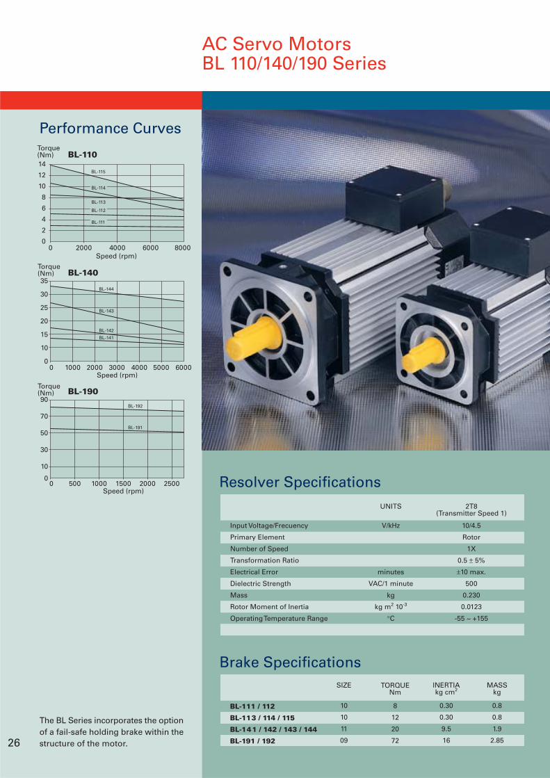
Resolver Specifications
Input Voltage/Frecuency
Primary Element
Number of Speed
Transformation Ratio
Electrical Error
Dielectric Strength
Mass
Rotor Moment of Inertia
Operating Temperature Range
UNITS
V/kHz
minutes
VAC/1 minute
kg
kg m2 10-3
°C
10/4.5
Rotor
1X
0.5 ± 5%
±10 max.
500
0.230
0.0123
-55 ~ +155
2T8(Transmitter Speed 1)
Brake Specifications
BL-111 / 112
BL-113 / 114 / 115
BL-141 / 142 / 143 / 144
BL-191 / 192
SIZE
10
10
11
09
TORQUENm
8
12
20
72
INERTIAkg cm2
0.30
0.30
9.5
16
MASSkg
0.8
0.8
1.9
2.85
Performance Curves
26
0 500 1000 1500 2000 2500
90
70
50
30
10
0
Speed (rpm)
BL-190Torque(Nm)
BL-192
BL-191
35
30
25
20
15
10
0
Speed (rpm)
BL-140Torque(Nm)
0 1000 2000 3000 4000 5000 6000
BL-144
BL-143
BL-142
BL-141
0 2000 4000 6000 8000
14
12
10
8
6
4
2
0
Speed (rpm)
BL-110Torque(Nm)
BL-115
BL-112
BL-111
BL-113
BL-114
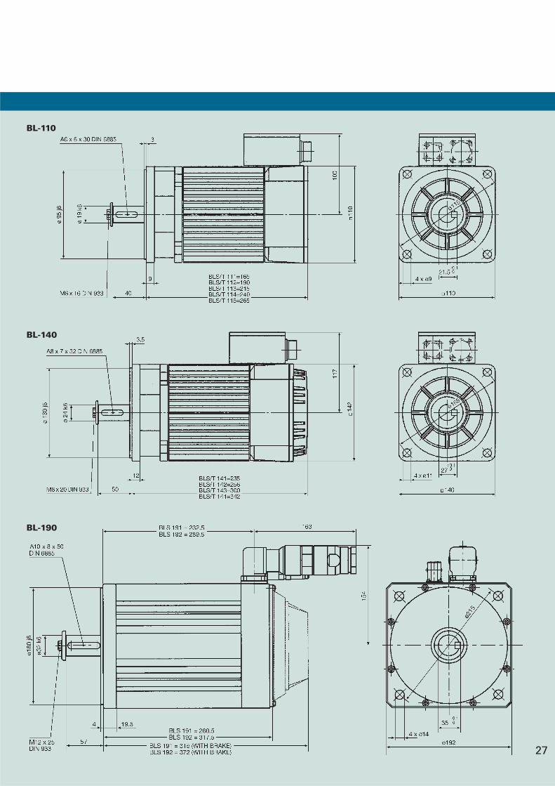
27
BL-110
BL-140
BL-190
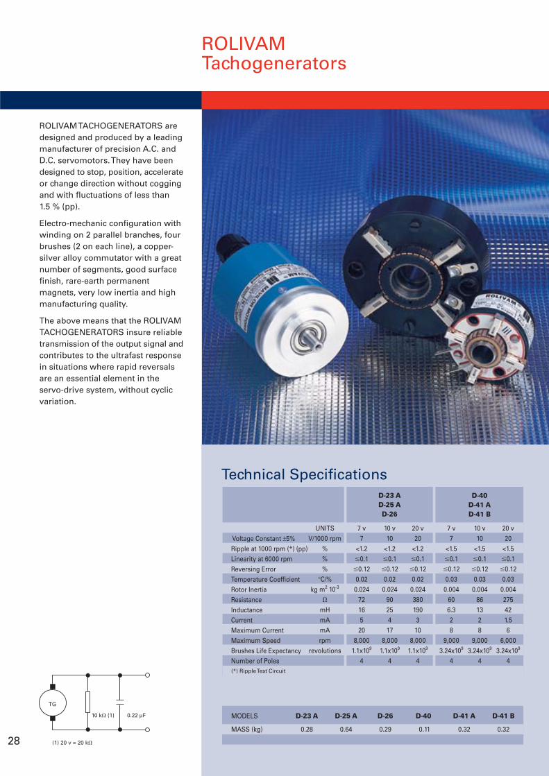
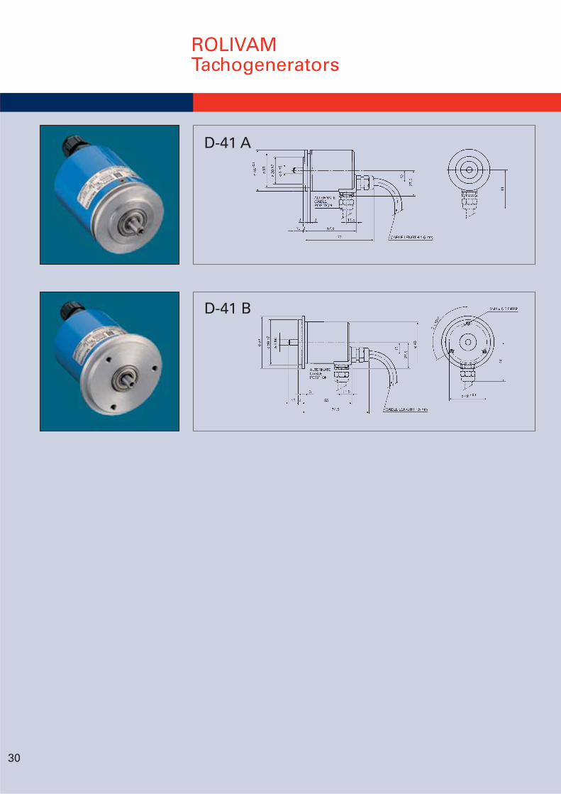
ROLIVAMTachogenerators
ROLIVAM TACHOGENERATORS aredesigned and produced by a leadingmanufacturer of precision A.C. andD.C. servomotors. They have beendesigned to stop, position, accelerateor change direction without coggingand with fluctuations of less than1.5 % (pp).
Electro-mechanic configuration withwinding on 2 parallel branches, fourbrushes (2 on each line), a copper-silver alloy commutator with a greatnumber of segments, good surfacefinish, rare-earth permanentmagnets, very low inertia and highmanufacturing quality.
The above means that the ROLIVAMTACHOGENERATORS insure reliabletransmission of the output signal andcontributes to the ultrafast responsein situations where rapid reversalsare an essential element in theservo-drive system, without cyclicvariation.
28 (1) 20 v = 20 k
TG
10 k (1) 0.22 µF MODELS D-23 A D-25 A D-26 D-40 D-41 A D-41 B
MASS (kg) 0.28 0.64 0.29 0.11 0.32 0.32
Technical Specifications
Voltage Constant ±5%Ripple at 1000 rpm (*) (pp)Linearity at 6000 rpmReversing ErrorTemperature CoefficientRotor InertiaResistanceInductanceCurrentMaximum CurrentMaximum SpeedBrushes Life ExpectancyNumber of Poles
UNITSV/1000 rpm
%%%
°C/%kg m2 10-3
mHmAmArpm
revolutions
7 v7
<1.20.1
0.120.020.024
7216520
8,0001.1x109
4
10 v10
<1.20.1
0.120.020.024
9025417
8,0001.1x109
4
20 v20
<1.20.1
0.120.020.024380190310
8,0001.1x109
4
7 v7
<1.50.1
0.120.03
0.004606.328
9,0003.24x109
4
10 v10
<1.50.1
0.120.03
0.004861328
9,0003.24x109
4
20 v20
<1.50.1
0.120.03
0.004275421.56
6,0003.24x109
4
D-40D-41 AD-41 B
D-23 AD-25 AD-26
(*) Ripple Test Circuit
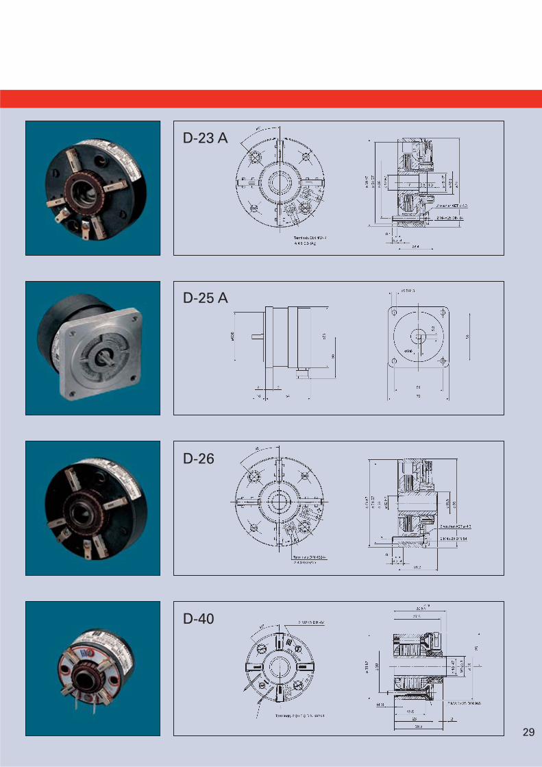
D-23 A
D-25 A
D-26
D-40
29
ROLIVAMTachogenerators
30
D-41 B
D-41 A
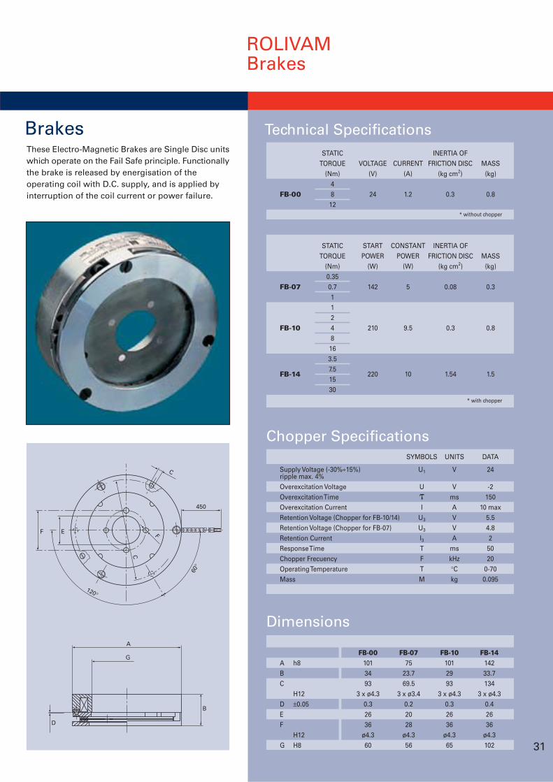
BrakesThese Electro-Magnetic Brakes are Single Disc unitswhich operate on the Fail Safe principle. Functionallythe brake is released by energisation of theoperating coil with D.C. supply, and is applied byinterruption of the coil current or power failure.
A h8BC
H12D ±0.05EF
H12G H8
FB-001013493
3 x ø4.30.32636
ø4.360
FB-0775
23.769.5
3 x ø3.40.22028
ø4.356
FB-101012993
3 x ø4.30.32636
ø4.365
FB-1414233.7134
3 x ø4.30.42636
ø4.3102
ROLIVAMBrakes
A
G
D
B
F E
450
F
C
C
60°
120°
Dimensions
31
Chopper Specifications
Supply Voltage (-30%÷15%)ripple max. 4%Overexcitation VoltageOverexcitation TimeOverexcitation CurrentRetention Voltage (Chopper for FB-10/14)Retention Voltage (Chopper for FB-07)Retention CurrentResponse TimeChopper FrecuencyOperating TemperatureMass
UNITS
V
VmsAVVA
mskHz°Ckg
DATA
24
-2150
10 max5.54.82
5020
0-700.095
SYMBOLS
U1
UI
U3
U3
I3TFTM
Technical Specifications
FB-00
STATICTORQUE
(Nm)4812
VOLTAGE(V)
24
CURRENT(A)
1.2
INERTIA OFFRICTION DISC
(kg cm2)
0.3
MASS(kg)
0.8
* without chopper
FB-07
FB-10
FB-14
STATICTORQUE
(Nm)0.350.711248163.57.51530
STARTPOWER
(W)
142
210
220
CONSTANTPOWER
(W)
5
9.5
10
INERTIA OFFRICTION DISC
(kg cm2)
0.08
0.3
1.54
MASS(kg)
0.3
0.8
1.5
* with chopper
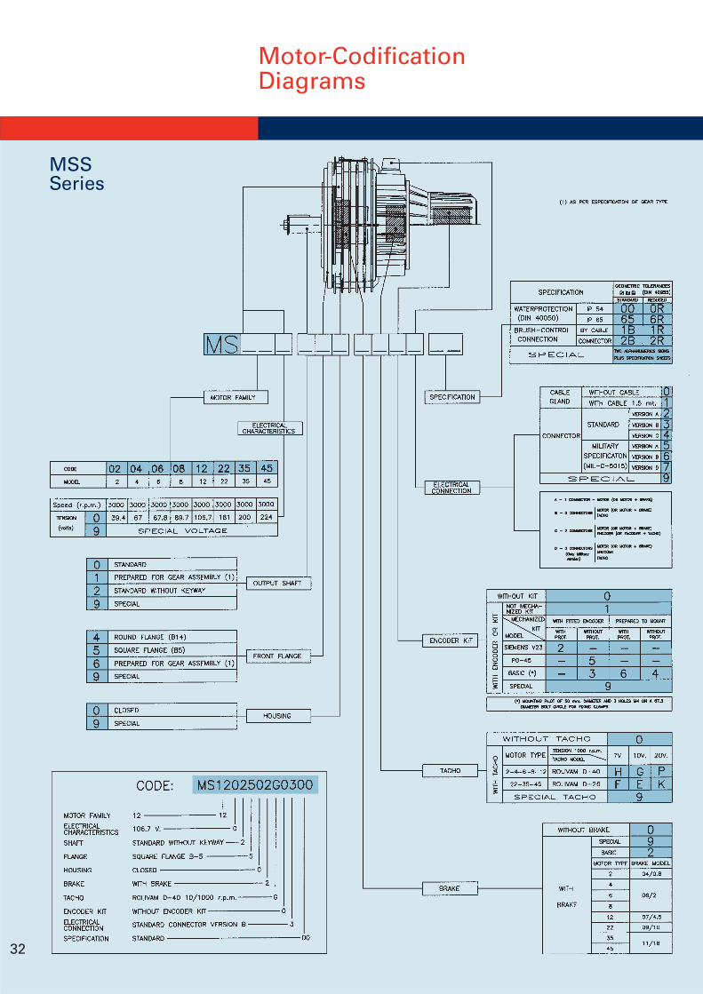
Motor-CodificationDiagrams
32
MSSSeries
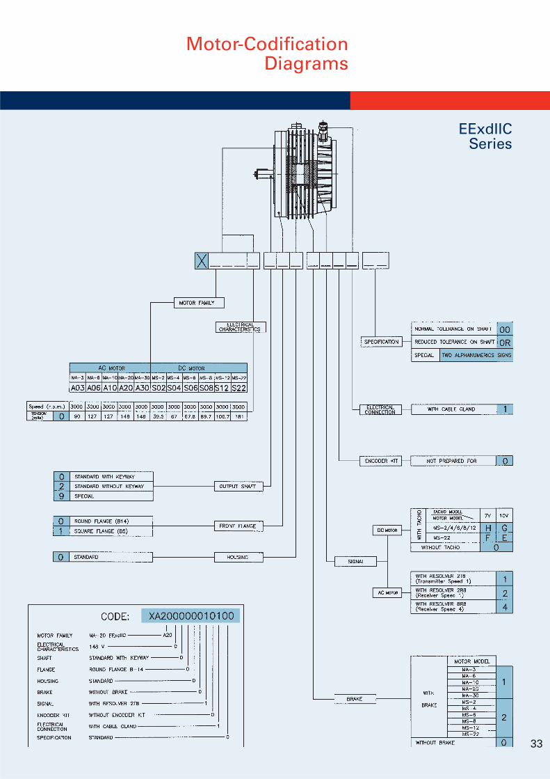
33
Motor-CodificationDiagrams
EExdIICSeries
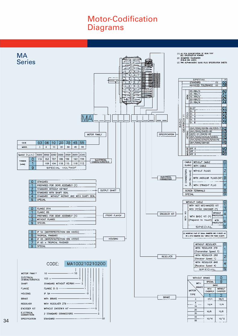
Motor-CodificationDiagrams
34
MASeries
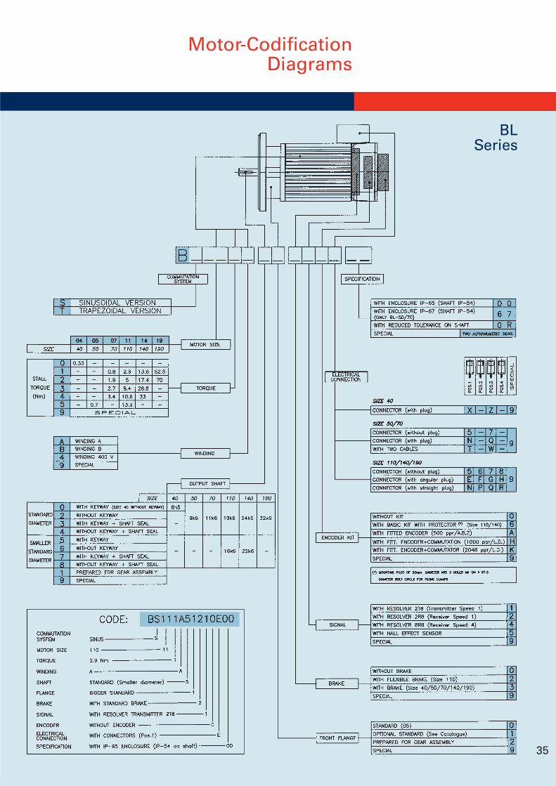
35
BLSeries
Motor-CodificationDiagrams
36
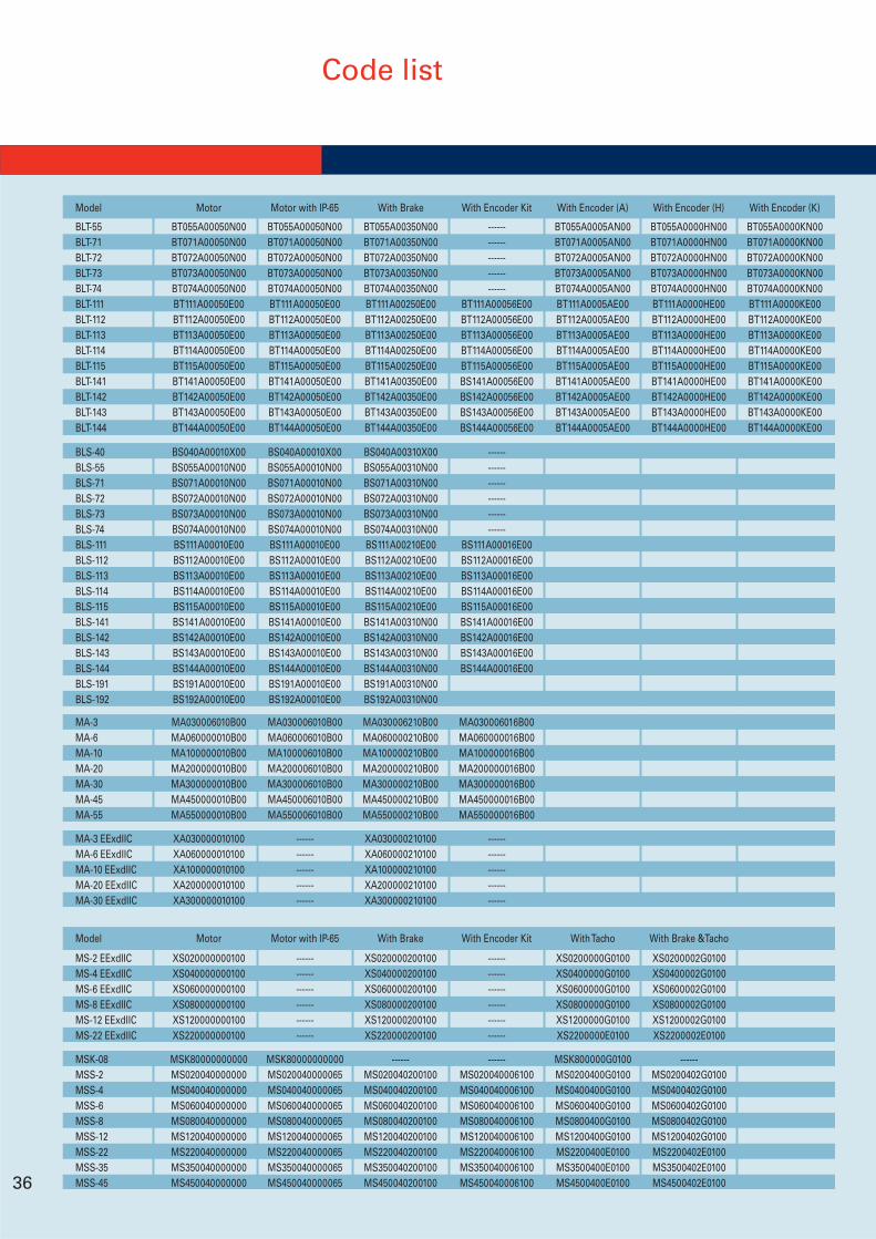
Code list
MSK-08 MSK80000000000 MSK80000000000 ------ ------ MSK800000G0100 ------MSS-2 MS020040000000 MS020040000065 MS020040200100 MS020040006100 MS0200400G0100 MS0200402G0100MSS-4 MS040040000000 MS040040000065 MS040040200100 MS040040006100 MS0400400G0100 MS0400402G0100MSS-6 MS060040000000 MS060040000065 MS060040200100 MS060040006100 MS0600400G0100 MS0600402G0100MSS-8 MS080040000000 MS080040000065 MS080040200100 MS080040006100 MS0800400G0100 MS0800402G0100MSS-12 MS120040000000 MS120040000065 MS120040200100 MS120040006100 MS1200400G0100 MS1200402G0100MSS-22 MS220040000000 MS220040000065 MS220040200100 MS220040006100 MS2200400E0100 MS2200402E0100MSS-35 MS350040000000 MS350040000065 MS350040200100 MS350040006100 MS3500400E0100 MS3500402E0100MSS-45 MS450040000000 MS450040000065 MS450040200100 MS450040006100 MS4500400E0100 MS4500402E0100
Model Motor Motor with IP-65 With Brake With Encoder Kit With Tacho With Brake &Tacho
MS-2 EExdIIC XS020000000100 ------ XS020000200100 ------ XS0200000G0100 XS0200002G0100MS-4 EExdIIC XS040000000100 ------ XS040000200100 ------ XS0400000G0100 XS0400002G0100MS-6 EExdIIC XS060000000100 ------ XS060000200100 ------ XS0600000G0100 XS0600002G0100MS-8 EExdIIC XS080000000100 ------ XS080000200100 ------ XS0800000G0100 XS0800002G0100MS-12 EExdIIC XS120000000100 ------ XS120000200100 ------ XS1200000G0100 XS1200002G0100MS-22 EExdIIC XS220000000100 ------ XS220000200100 ------ XS2200000E0100 XS2200002E0100
MA-3 EExdIIC XA030000010100 ------ XA030000210100 ------MA-6 EExdIIC XA060000010100 ------ XA060000210100 ------MA-10 EExdIIC XA100000010100 ------ XA100000210100 ------MA-20 EExdIIC XA200000010100 ------ XA200000210100 ------MA-30 EExdIIC XA300000010100 ------ XA300000210100 ------
Model Motor Motor with IP-65 With Brake With Encoder Kit With Encoder (A) With Encoder (H) With Encoder (K)
BLT-55 BT055A00050N00 BT055A00050N00 BT055A00350N00 ------ BT055A0005AN00 BT055A0000HN00 BT055A0000KN00BLT-71 BT071A00050N00 BT071A00050N00 BT071A00350N00 ------ BT071A0005AN00 BT071A0000HN00 BT071A0000KN00BLT-72 BT072A00050N00 BT072A00050N00 BT072A00350N00 ------ BT072A0005AN00 BT072A0000HN00 BT072A0000KN00BLT-73 BT073A00050N00 BT073A00050N00 BT073A00350N00 ------ BT073A0005AN00 BT073A0000HN00 BT073A0000KN00BLT-74 BT074A00050N00 BT074A00050N00 BT074A00350N00 ------ BT074A0005AN00 BT074A0000HN00 BT074A0000KN00BLT-111 BT111A00050E00 BT111A00050E00 BT111A00250E00 BT111A00056E00 BT111A0005AE00 BT111A0000HE00 BT111A0000KE00BLT-112 BT112A00050E00 BT112A00050E00 BT112A00250E00 BT112A00056E00 BT112A0005AE00 BT112A0000HE00 BT112A0000KE00BLT-113 BT113A00050E00 BT113A00050E00 BT113A00250E00 BT113A00056E00 BT113A0005AE00 BT113A0000HE00 BT113A0000KE00BLT-114 BT114A00050E00 BT114A00050E00 BT114A00250E00 BT114A00056E00 BT114A0005AE00 BT114A0000HE00 BT114A0000KE00BLT-115 BT115A00050E00 BT115A00050E00 BT115A00250E00 BT115A00056E00 BT115A0005AE00 BT115A0000HE00 BT115A0000KE00BLT-141 BT141A00050E00 BT141A00050E00 BT141A00350E00 BS141A00056E00 BT141A0005AE00 BT141A0000HE00 BT141A0000KE00BLT-142 BT142A00050E00 BT142A00050E00 BT142A00350E00 BS142A00056E00 BT142A0005AE00 BT142A0000HE00 BT142A0000KE00BLT-143 BT143A00050E00 BT143A00050E00 BT143A00350E00 BS143A00056E00 BT143A0005AE00 BT143A0000HE00 BT143A0000KE00BLT-144 BT144A00050E00 BT144A00050E00 BT144A00350E00 BS144A00056E00 BT144A0005AE00 BT144A0000HE00 BT144A0000KE00
BLS-40 BS040A00010X00 BS040A00010X00 BS040A00310X00 ------BLS-55 BS055A00010N00 BS055A00010N00 BS055A00310N00 ------BLS-71 BS071A00010N00 BS071A00010N00 BS071A00310N00 ------BLS-72 BS072A00010N00 BS072A00010N00 BS072A00310N00 ------BLS-73 BS073A00010N00 BS073A00010N00 BS073A00310N00 ------BLS-74 BS074A00010N00 BS074A00010N00 BS074A00310N00 ------BLS-111 BS111A00010E00 BS111A00010E00 BS111A00210E00 BS111A00016E00BLS-112 BS112A00010E00 BS112A00010E00 BS112A00210E00 BS112A00016E00BLS-113 BS113A00010E00 BS113A00010E00 BS113A00210E00 BS113A00016E00BLS-114 BS114A00010E00 BS114A00010E00 BS114A00210E00 BS114A00016E00BLS-115 BS115A00010E00 BS115A00010E00 BS115A00210E00 BS115A00016E00BLS-141 BS141A00010E00 BS141A00010E00 BS141A00310N00 BS141A00016E00BLS-142 BS142A00010E00 BS142A00010E00 BS142A00310N00 BS142A00016E00BLS-143 BS143A00010E00 BS143A00010E00 BS143A00310N00 BS143A00016E00BLS-144 BS144A00010E00 BS144A00010E00 BS144A00310N00 BS144A00016E00BLS-191 BS191A00010E00 BS191A00010E00 BS191A00310N00BLS-192 BS192A00010E00 BS192A00010E00 BS192A00310N00
MA-3 MA030006010B00 MA030006010B00 MA030006210B00 MA030006016B00MA-6 MA060000010B00 MA060006010B00 MA060000210B00 MA060000016B00MA-10 MA100000010B00 MA100006010B00 MA100000210B00 MA100000016B00MA-20 MA200000010B00 MA200006010B00 MA200000210B00 MA200000016B00MA-30 MA300000010B00 MA300006010B00 MA300000210B00 MA300000016B00MA-45 MA450000010B00 MA450006010B00 MA450000210B00 MA450000016B00MA-55 MA550000010B00 MA550006010B00 MA550000210B00 MA550000016B00
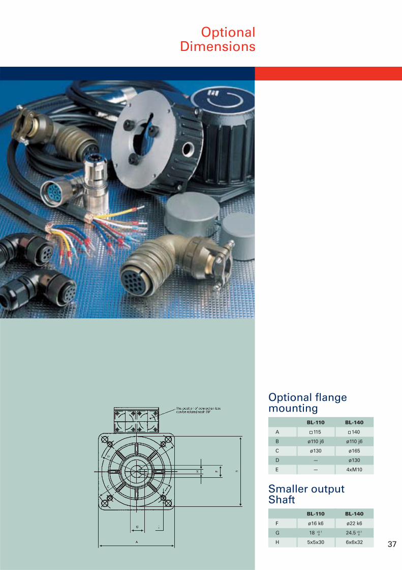
OptionalDimensions
37
Optional flangemounting
BL-110
115
ø110 j6
ø130
—
—
BL-140
140
ø110 j6
ø165
ø130
4xM10
A
B
C
D
E
BL-110
ø16 k6
18
5x5x30
+0.10
+0.10
BL-140
ø22 k6
24.5
6x6x32
F
G
H
Smaller outputShaft
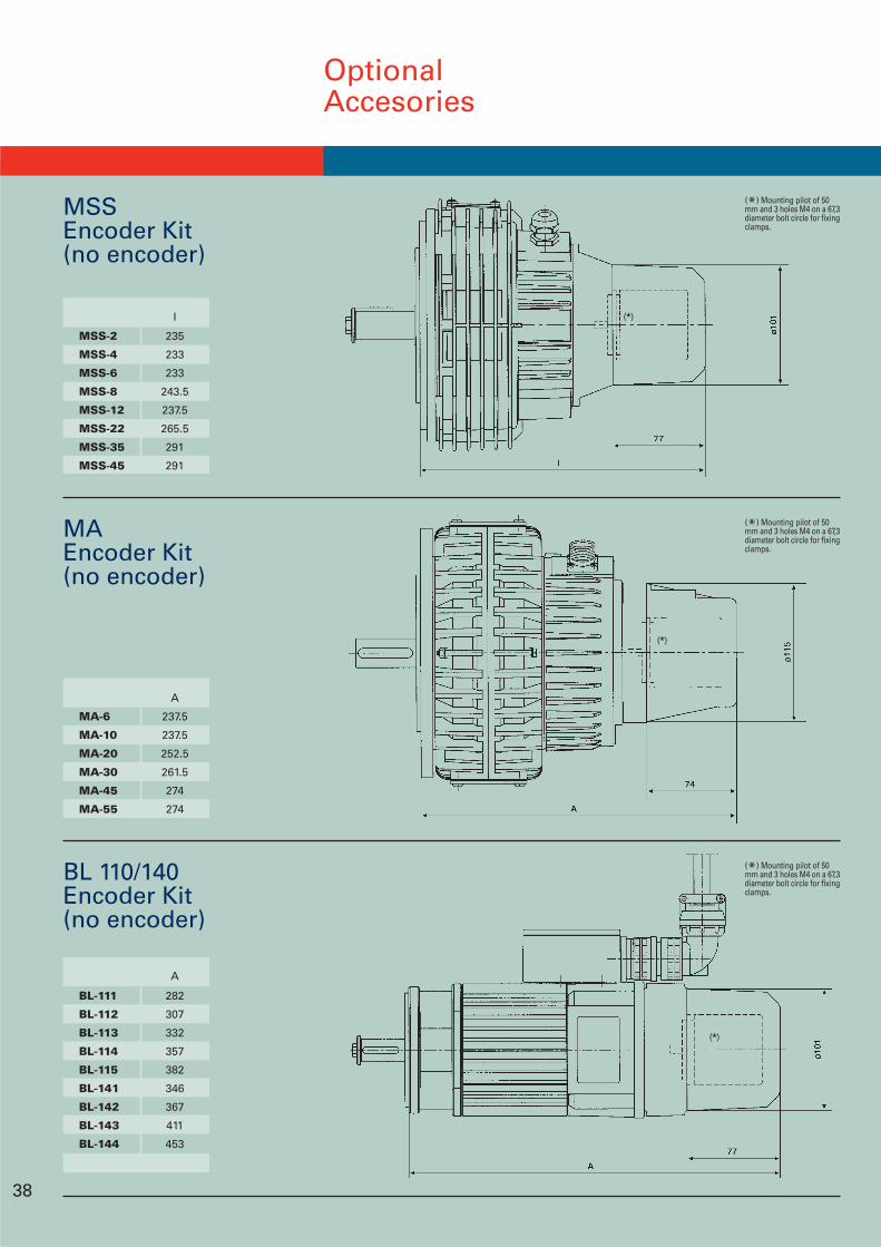
OptionalAccesories
I
MSS-2 235
MSS-4 233
MSS-6 233
MSS-8 243.5
MSS-12 237.5
MSS-22 265.5
MSS-35 291
MSS-45 291
A
MA-6 237.5
MA-10 237.5
MA-20 252.5
MA-30 261.5
MA-45 274
MA-55 274
A
BL-111 282
BL-112 307
BL-113 332
BL-114 357
BL-115 382
BL-141 346
BL-142 367
BL-143 411
BL-144 453
MSSEncoder Kit(no encoder)
MAEncoder Kit(no encoder)
BL 110/140Encoder Kit(no encoder)
(*)
(*)
(*)
(*) Mounting pilot of 50mm and 3 holes M4 on a 67,3diameter bolt circle for fixingclamps.
38
(*) Mounting pilot of 50mm and 3 holes M4 on a 67,3diameter bolt circle for fixingclamps.
(*) Mounting pilot of 50mm and 3 holes M4 on a 67,3diameter bolt circle for fixingclamps.
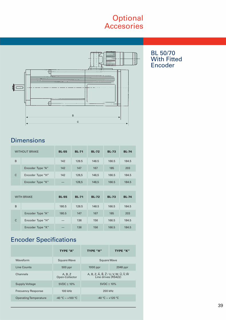
OptionalAccesories
BL 50/70With FittedEncoder
39
Encoder Specifications
TYPE “A”
Square Wave
500 ppr
A, B, ZOpen-Collector
5VDC ± 10%
100 kHz
-40 ºC ~ +100 ºC
Waveform
Line Counts
Channels
Supply Voltage
Frecuency Response
Operating Temperature
_ _ _ _ _ _
Square Wave
A, B, Z, A, B, Z / U, V, W, U, V, WLine drives (RS422)
5VDC ± 10%
200 kHz
-40 ºC ~ +120 ºC
TYPE “H”
1000 ppr
TYPE “K”
2048 ppr
BL-73
166.5
185
166.5
166.5
BL-72
148.5
167
156
156
BL-71
128.5
147
136
136
BL-55
180.5
180.5
----
----
WITH BRAKE
B
Encoder Type “A”
C Encoder Type “H”
Encoder Type “K”
BL-74
184.5
203
184.5
184.5
Dimensions
BL-74
184.5
203
184.5
184.5
BL-73
166.5
185
166.5
166.5
BL-71
128.5
147
128,5
128,5
BL-72
148.5
167
148,5
148,5
WITHOUT BRAKE
B
Encoder Type “A”
C Encoder Type “H”
Encoder Type “K”
BL-55
142
142
142
----
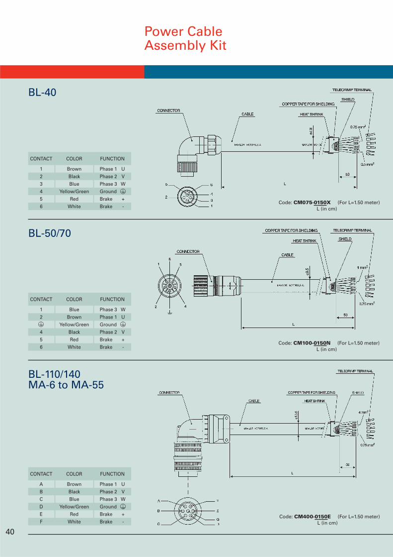
CONTACT COLOR FUNCTION
A Brown Phase 1 U
B Black Phase 2 V
C Blue Phase 3 W
D Yellow/Green Ground
E Red Brake +
F White Brake -
CONTACT COLOR FUNCTION
1 Brown Phase 1 U
2 Black Phase 2 V
3 Blue Phase 3 W
4 Yellow/Green Ground
5 Red Brake +
6 White Brake -
CONTACT COLOR FUNCTION
1 Blue Phase 3 W
2 Brown Phase 1 U
Yellow/Green Ground
4 Black Phase 2 V
5 Red Brake +
6 White Brake -
Power CableAssembly Kit
BL-40
BL-50/70
BL-110/140MA-6 to MA-55
40
Code: CM075-0150X (For L=1.50 meter)L (in cm)
Code: CM100-0150N (For L=1.50 meter)L (in cm)
Code: CM400-0150E (For L=1.50 meter)L (in cm)
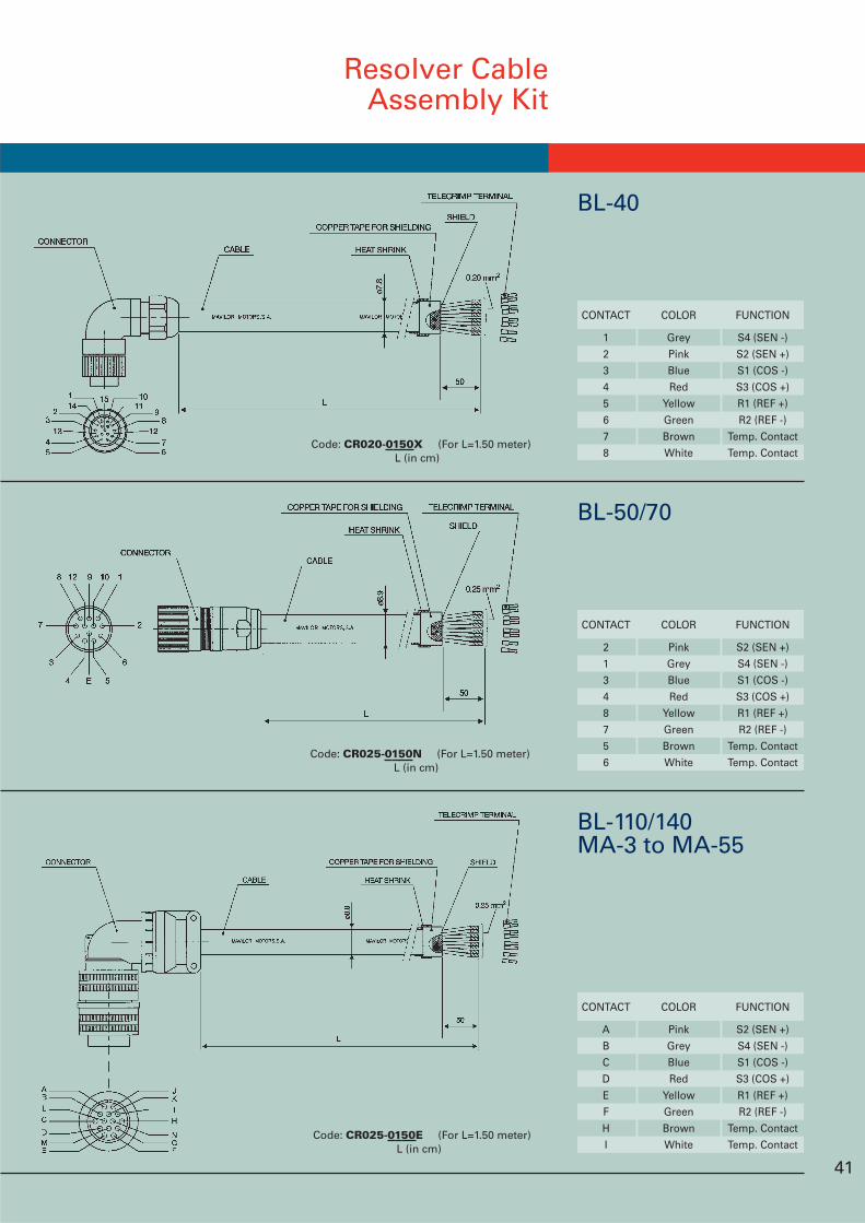
Resolver CableAssembly Kit
CONTACT COLOR FUNCTION
A Pink S2 (SEN +)
B Grey S4 (SEN -)
C Blue S1 (COS -)
D Red S3 (COS +)
E Yellow R1 (REF +)
F Green R2 (REF -)
H Brown Temp. Contact
I White Temp. Contact
CONTACT COLOR FUNCTION
2 Pink S2 (SEN +)
1 Grey S4 (SEN -)
3 Blue S1 (COS -)
4 Red S3 (COS +)
8 Yellow R1 (REF +)
7 Green R2 (REF -)
5 Brown Temp. Contact
6 White Temp. Contact
CONTACT COLOR FUNCTION
1 Grey S4 (SEN -)
2 Pink S2 (SEN +)
3 Blue S1 (COS -)
4 Red S3 (COS +)
5 Yellow R1 (REF +)
6 Green R2 (REF -)
7 Brown Temp. Contact
8 White Temp. Contact
41
BL-40
BL-50/70
BL-110/140MA-3 to MA-55
Code: CR025-0150E (For L=1.50 meter)L (in cm)
Code: CR025-0150N (For L=1.50 meter)L (in cm)
Code: CR020-0150X (For L=1.50 meter)L (in cm)
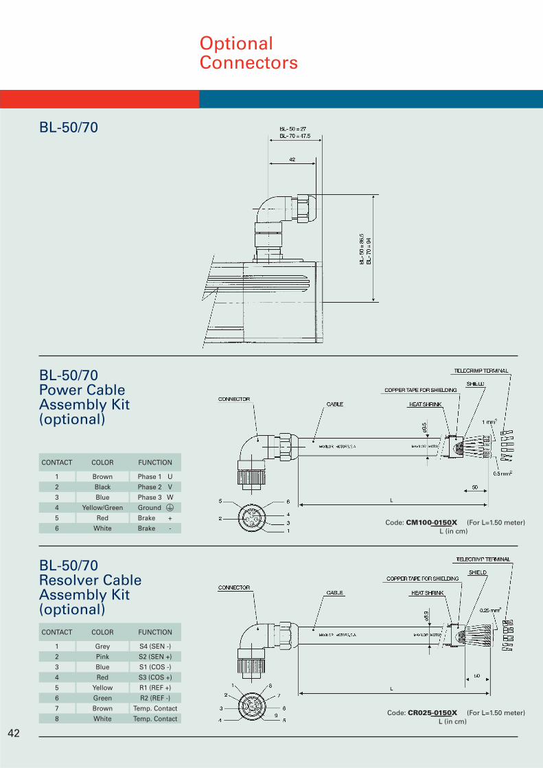
CONTACT COLOR FUNCTION
1 Brown Phase 1 U
2 Black Phase 2 V
3 Blue Phase 3 W
4 Yellow/Green Ground
5 Red Brake +
6 White Brake -
OptionalConnectors
BL-50/70
BL-50/70Power CableAssembly Kit(optional)
BL-50/70Resolver CableAssembly Kit(optional)CONTACT COLOR FUNCTION
1 Grey S4 (SEN -)
2 Pink S2 (SEN +)
3 Blue S1 (COS -)
4 Red S3 (COS +)
5 Yellow R1 (REF +)
6 Green R2 (REF -)
7 Brown Temp. Contact
8 White Temp. Contact
42
Code: CM100-0150X (For L=1.50 meter)L (in cm)
Code: CR025-0150X (For L=1.50 meter)L (in cm)
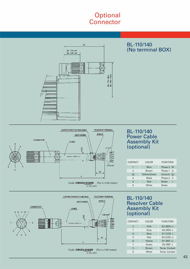
OptionalConnector
BL-110/140(No terminal BOX)
BL-110/140Power CableAssembly Kit(optional)
BL-110/140Resolver CableAssembly Kit(optional)CONTACT COLOR FUNCTION
2 Pink S2 (SEN +)
1 Grey S4 (SEN -)
3 Blue S1 (COS -)
4 Red S3 (COS +)
8 Yellow R1 (REF +)
7 Green R2 (REF -)
5 Brown Temp. Contact
6 White Temp. Contact
43
CONTACT COLOR FUNCTION
1 Blue Phase 3 W
2 Brown Phase 1 U
Yellow/Green Ground
4 Black Phase 2 V
5 Red Brake +
6 White Brake -
Code: CR025-0150N (For L=1.50 meter)L (in cm)
Code: CM400-0150N (For L=1.50 meter)L (in cm)
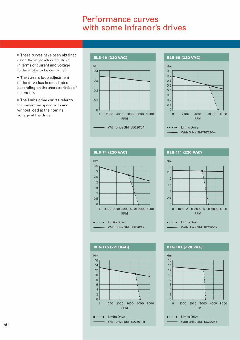
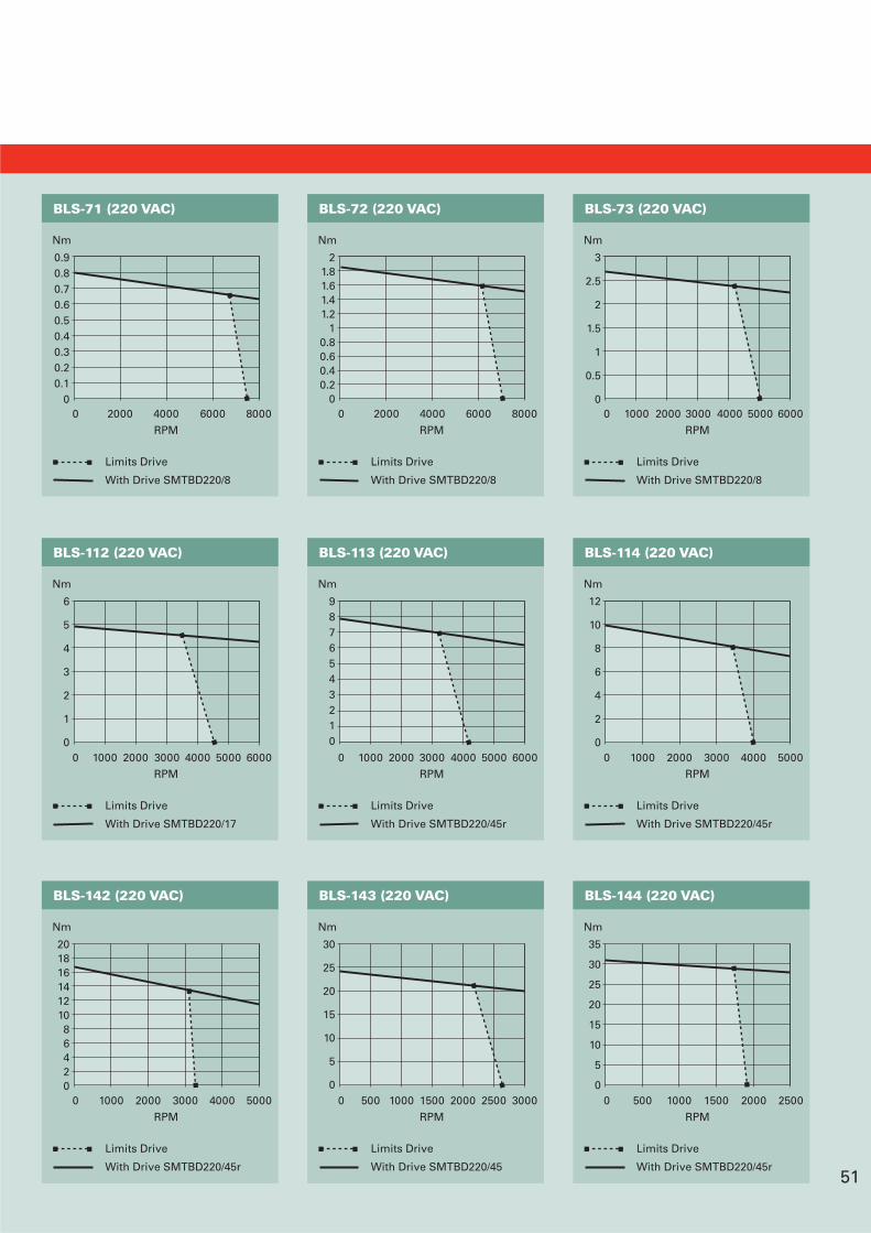
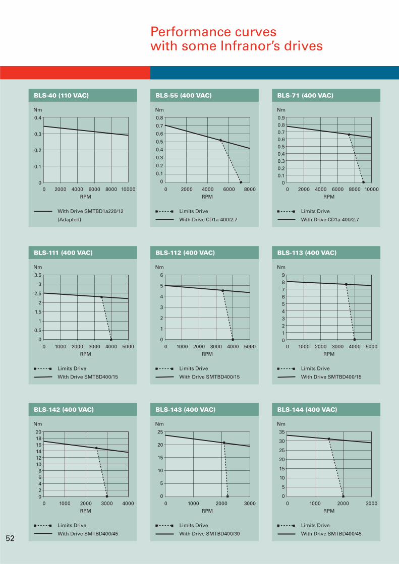
Performance curveswith some Infranor’s drives
0.8
0.7
0.6
0.5
0.4
0.3
0.2
0.1
00 2000 4000 6000 8000
RPM
Nm
BLS-55 (220 VAC)
Limits Drive
With Drive SMTBD220/4
0.4
0.3
0.2
0.1
00 2000 4000 6000 8000 10000
RPM
Nm
BLS-40 (220 VAC)
With Drive SMTBD220/04
3.5
3
2.5
2
1.5
1
0.5
0
0 1000 2000 3000 4000 5000 6000RPM
Nm
BLS-74 (220 VAC)
Limits Drive
With Drive SMTBD220/12
3
2.5
2
1.5
1
0.5
0
0 1000 2000 3000 4000 5000 6000RPM
Nm
BLS-111 (220 VAC)
Limits Drive
With Drive SMTBD220/12
16
14
12
10
8
6
4
2
00 1000 2000 3000 4000 5000
RPM
Nm
BLS-115 (220 VAC)
Limits Drive
With Drive SMTBD220/45r
16
14
12
10
8
6
4
2
00 1000 2000 3000 4000 5000
RPM
Nm
BLS-141 (220 VAC)
Limits Drive
With Drive SMTBD220/45r50
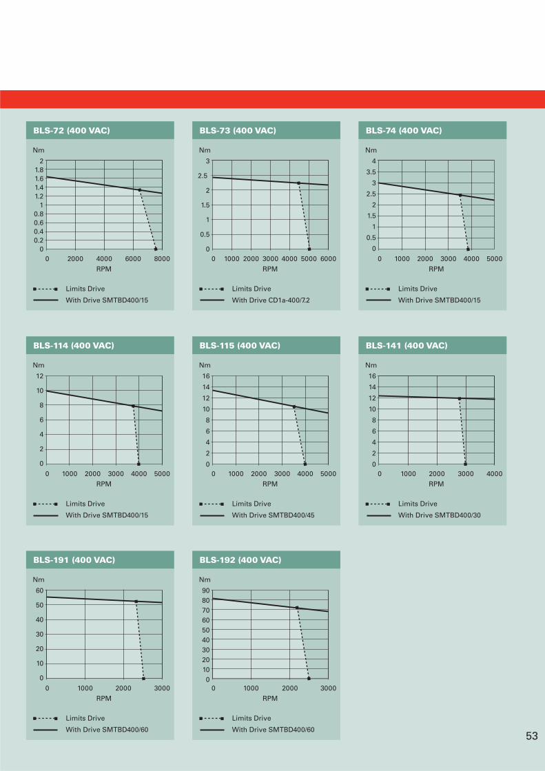
• These curves have been obtainedusing the most adequate drivein terms of current and voltageto the motor to be controlled.
• The current loop adjustmentof the drive has been adapteddepending on the characteristics ofthe motor.
• The limits drive curves refer tothe maximum speed with andwithout load at the nominalvoltage of the drive.
21.81.61.41.2
10.80.60.40.2
00 2000 4000 6000 8000
RPM
Nm
BLS-72 (220 VAC)
Limits Drive
With Drive SMTBD220/8
0.90.80.70.60.50.40.30.20.1
00 2000 4000 6000 8000
RPM
Nm
BLS-71 (220 VAC)
Limits Drive
With Drive SMTBD220/8
6
5
4
3
2
1
00 1000 2000 3000 4000 5000 6000
RPM
Nm
BLS-112 (220 VAC)
Limits Drive
With Drive SMTBD220/17
9876543210
0 1000 2000 3000 4000 5000 6000RPM
Nm
BLS-113 (220 VAC)
Limits Drive
With Drive SMTBD220/45r
12
10
8
6
4
2
00 1000 2000 3000 4000 5000
RPM
Nm
BLS-114 (220 VAC)
Limits Drive
With Drive SMTBD220/45r
20181614121086420
0 1000 2000 3000 4000 5000RPM
Nm
BLS-142 (220 VAC)
Limits Drive
With Drive SMTBD220/45r51
3
2.5
2
1.5
1
0.5
00 1000 2000 3000 4000 5000 6000
RPM
Nm
BLS-73 (220 VAC)
Limits Drive
With Drive SMTBD220/8
30
25
20
15
10
5
00 500 1000 1500 2000 2500 3000
RPM
Nm
BLS-143 (220 VAC)
Limits Drive
With Drive SMTBD220/45
35
30
25
20
15
10
5
00 500 1000 1500 2000 2500
RPM
Nm
BLS-144 (220 VAC)
Limits Drive
With Drive SMTBD220/45r
Performance curveswith some Infranor’s drives
0.4
0.3
0.2
0.1
00 2000 4000 6000 8000 10000
RPM
Nm
BLS-40 (110 VAC)
With Drive SMTBD1a220/12
(Adapted)
0.8
0.7
0.6
0.5
0.4
0.3
0.2
0.1
0
0 2000 4000 6000 8000RPM
Nm
BLS-55 (400 VAC)
Limits Drive
With Drive CD1a-400/2.7
0.90.80.70.60.50.40.30.20.1
00 2000 4000 6000 8000 10000
RPM
Nm
BLS-71 (400 VAC)
Limits Drive
With Drive CD1a-400/2.7
6
5
4
3
2
1
00 1000 2000 3000 4000 5000
RPM
Nm
BLS-112 (400 VAC)
Limits Drive
With Drive SMTBD400/15
3.5
3
2.5
2
1.5
1
0.5
00 1000 2000 3000 4000 5000
RPM
Nm
BLS-111 (400 VAC)
Limits Drive
With Drive SMTBD400/15
9876543210
0 1000 2000 3000 4000 5000RPM
Nm
BLS-113 (400 VAC)
Limits Drive
With Drive SMTBD400/15
35
30
25
20
15
10
5
00 1000 2000 3000
RPM
Nm
BLS-144 (400 VAC)
Limits Drive
With Drive SMTBD400/45
25
20
15
10
5
00 1000 2000 3000
RPM
Nm
BLS-143 (400 VAC)
Limits Drive
With Drive SMTBD400/30
20181614121086420
0 1000 2000 3000 4000RPM
Nm
BLS-142 (400 VAC)
Limits Drive
With Drive SMTBD400/4552
21.81.61.41.2
10.80.60.40.2
00 2000 4000 6000 8000
RPM
Nm
BLS-72 (400 VAC)
Limits Drive
With Drive SMTBD400/15
3
2.5
2
1.5
1
0.5
00 1000 2000 3000 4000 5000 6000
RPM
Nm
BLS-73 (400 VAC)
Limits Drive
With Drive CD1a-400/7.2
4
3.5
3
2.5
2
1.5
1
0.5
00 1000 2000 3000 4000 5000
RPM
Nm
BLS-74 (400 VAC)
Limits Drive
With Drive SMTBD400/15
16
14
12
10
8
6
4
2
00 1000 2000 3000 4000
RPM
Nm
BLS-141 (400 VAC)
Limits Drive
With Drive SMTBD400/30
9080706050403020100
0 1000 2000 3000RPM
Nm
BLS-192 (400 VAC)
Limits Drive
With Drive SMTBD400/60
60
50
40
30
20
10
00 1000 2000 3000
RPM
Nm
BLS-191 (400 VAC)
Limits Drive
With Drive SMTBD400/60
16
14
12
10
8
6
4
2
00 1000 2000 3000 4000 5000
RPM
Nm
BLS-115 (400 VAC)
Limits Drive
With Drive SMTBD400/45
12
10
8
6
4
2
00 1000 2000 3000 4000 5000
RPM
Nm
BLS-114 (400 VAC)
Limits Drive
With Drive SMTBD400/15
53
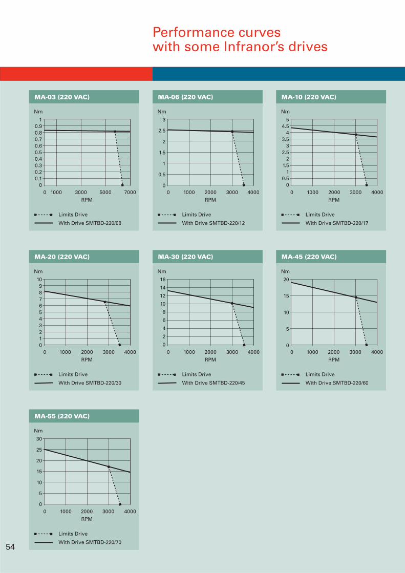
Performance curveswith some Infranor’s drives
54
54.5
43.5
32.5
21.5
10.5
00 1000 2000 3000 4000
RPM
Nm
MA-10 (220 VAC)
Limits Drive
With Drive SMTBD-220/17
3
2.5
2
1.5
1
0.5
00 1000 2000 3000 4000
RPM
Nm
MA-06 (220 VAC)
Limits Drive
With Drive SMTBD-220/12
20
15
10
5
00 1000 2000 3000 4000
RPM
Nm
MA-45 (220 VAC)
Limits Drive
With Drive SMTBD-220/60
16
14
12
10
8
6
4
2
00 1000 2000 3000 4000
RPM
Nm
MA-30 (220 VAC)
Limits Drive
With Drive SMTBD-220/45
109876543210
0 1000 2000 3000 4000RPM
Nm
MA-20 (220 VAC)
Limits Drive
With Drive SMTBD-220/30
30
25
20
15
10
5
00 1000 2000 3000 4000
RPM
Nm
MA-55 (220 VAC)
Limits Drive
With Drive SMTBD-220/70
10.90.80.70.60.50.40.30.20.1
00 1000 3000 5000 7000
RPM
Nm
MA-03 (220 VAC)
Limits Drive
With Drive SMTBD-220/08

MAVILOR MOTORS, S.A.
Polígono Industrial URVASAC/ Empordà 11-1308130 Sta. Perpètua de Mogoda(Barcelona) - SPAINTel. +34 935 743 690Fax +34 935 743 570E-mail: [email protected]: //www.mavilor.es