Embed Size (px)
Citation preview
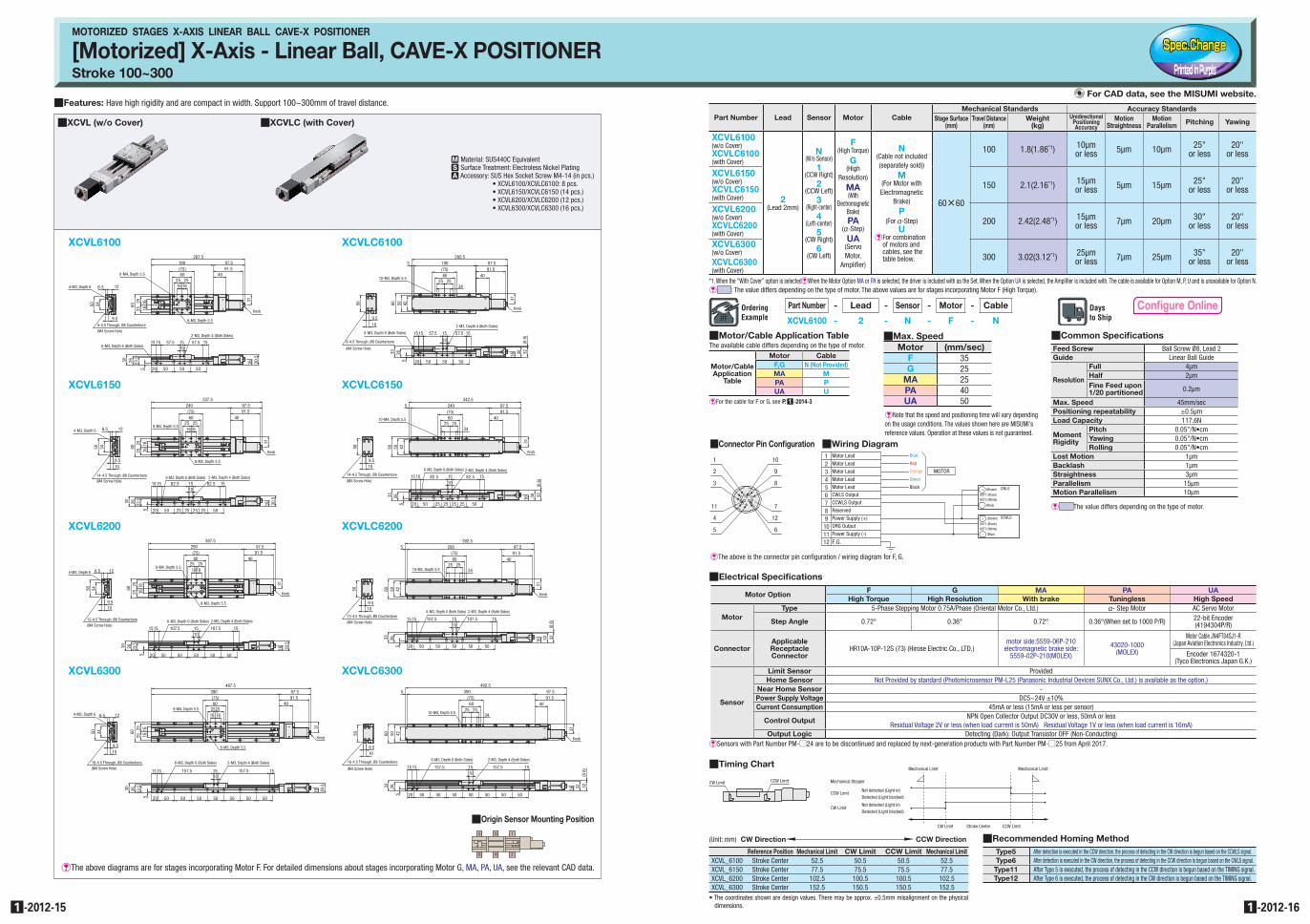
EThe above diagrams are for stages incorporating Motor F. For detailed dimensions about stages incorporating Motor G, MA, PA, UA, see the relevant CAD data.
QFeatures: Have high rigidity and are compact in width. Support 100~300mm of travel distance.
MOTORIZED STAGES X-AXIS LINEAR BALL CAVE-X POSITIONER
[Motorized] X-Axis - Linear Ball, CAVE-X POSITIONERStroke 100~300
QXCVL (w/o Cover) QXCVLC (with Cover)
M Material: SUS440C EquivalentS Surface Treatment: Electroless Nickel PlatingA Accessory: SUS Hex Socket Screw M4-14 (in pcs.)
• XCVL6100/XCVLC6100: 8 pcs.• XCVL6150/XCVLC6150 (14 pcs.)• XCVL6200/XCVLC6200 (12 pcs.)• XCVL6300/XCVLC6300 (16 pcs.)
Type5 After detection is executed in the CCW direction, the process of detecting in the CW direction is begun based on the CCWLS signal.Type6 After detection is executed in the CW direction, the process of detecting in the CCW direction is begun based on the CWLS signal.Type11 After Type 5 is executed, the process of detecting in the CCW direction is begun based on the TIMING signal.Type12 After Type 6 is executed, the process of detecting in the CW direction is begun based on the TIMING signal.
QRecommended Homing MethodReference Position Mechanical Limit CW Limit CCW Limit Mechanical Limit
XCVL_6100 Stroke Center 52.5 50.5 50.5 52.5XCVL_6150 Stroke Center 77.5 75.5 75.5 77.5XCVL_6200 Stroke Center 102.5 100.5 100.5 102.5XCVL_6300 Stroke Center 152.5 150.5 150.5 152.5
• The coordinates shown are design values. There may be approx. ±0.5mm misalignment on the physical dimensions.
(Unit: mm) CW Direction CCW Direction
Mechanical Stopper
CCW Limit
CW Limit
Not detected (Light in)
Detected (Light blocked)
Not detected (Light in)
Detected (Light blocked)
CW Limit CCW Limit
CW Limit Stroke Center CCW Limit
Mechanical Limit Mechanical LimitQTiming Chart
*1. When the “With Cover” option is selectedEWhen the Motor Option MA or PA is selected, the driver is included with as the Set. When the Option UA is selected, the Amplifier is included with. The cable is available for Option M, P, U and is unavailable for Option N.E : The value differs depending on the type of motor. The above values are for stages incorporating Motor F (High Torque).
Part Number Lead Sensor Motor CableMechanical Standards Accuracy Standards
Stage Surface(mm)
Travel Distance(mm)
Weight(kg)
Unidirectional Positioning Accuracy
MotionStraightness
MotionParallelism Pitching Yawing
XCVL6100(w/o Cover)XCVLC6100(with Cover)
2(Lead 2mm)
N(W/o Sensor)
1(CCW Right)
2(CCW Left)
3(Right-center)
4(Left-center)
5(CW Right)
6(CW Left)
F (High Torque)
G (High
Resolution)
MA (With
Electromagnetic Brake)PA
(@-Step)
UA (Servo Motor,
Amplifier)
N(Cable not included (separately sold))
M(For Motor with Electromagnetic
Brake)
P(For @-Step)
UE�For combination
of motors and cables, see the table below.
60n60
100 1.8(1.86*1) 10µm or less 5µm 10µm 25"
or less20"
or less
XCVL6150(w/o Cover)XCVLC6150(with Cover)
150 2.1(2.16*1) 15µm or less 5µm 15µm 25"
or less20"
or less
XCVL6200(w/o Cover)XCVLC6200(with Cover)
200 2.42(2.48*1) 15µm or less 7µm 20µm 30"
or less20"
or less
XCVL6300(w/o Cover)XCVLC6300(with Cover)
300 3.02(3.12*1) 25µm or less 7µm 25µm 35"
or less20"
or less
XCVL6100
8-4.5 Through, Ø8 Counterbore(M4 Screw Hole)
4-M3, Depth 6 6.5 12
3450
9.5
8-M4, Depth 5.5
8-M3, Depth 5.5
6025
25 1616
287.597.5190
(75)60
25 2516 16
91.540
Knob
31
2-M3, Depth 4 (Both Sides)
6-M3, Depth 6 (Both Sides)
30.5
16
1015 15 15 15
50 50 5020
30 26 23.5
5
57.5 57.5
XCVL6150
14-4.5 Through, Ø8 Counterbore(M4 Screw Hole)
4-M3, Depth 6
9.510
3450
6.5 128-M4, Depth 5.5
8-M3, Depth 5.5
6025 16
1625
337.5240(75)60
25251616
97.591.5
40
31
Knob
6-M3, Depth 6 (Both Sides) 2-M3, Depth 4 (Both Sides)
10
30 26 23.5
5
30.5
16
20 50 25 25 25 25 50
82.5 82.515 15 15 15
XCVL6200
12-4.5 Through, Ø8 Counterbore(M4 Screw Hole)
4-M3, Depth 6 6.5
9.510
12
50 34
8-M4, Depth 5.5
8-M3, Depth 5.5
6025 16
1625
387.5
(75)60
25251616
29091.5
40
97.5
Knob
31
2-M3, Depth 4 (Both Sides)6-M3, Depth 6 (Both Sides)
10
30 26 23.5
5
30.5
16
15 15 1515 107.5 107.5
20 50 50 50 50 50
XCVL6300
16-4.5 Through, Ø8 Counterbore(M4 Screw Hole)
4-M3, Depth 6
3450
9.510
6.5 128-M4, Depth 5.5
8-M3, Depth 5.5
6025
2516
16
487.5390(75)60
25251616
97.591.5
40
Knob
31
15 151510
30 26 23.5
5
30.5
16
6-M3, Depth 6 (Both Sides) 2-M3, Depth 4 (Both Sides)
157.5 15157.5
20 50 50 50 50 50 50 50
XCVLC6100
8-4.5 Through, Ø8 Counterbore
50
109.5
5060 42
10-M4, Depth 5.5
292.597.5190
60(75)
2525
91.540
34
31
5
Knob
2-M3, Depth 4 (Both Sides)
6-M3, Depth 6 (Both Sides)
10
33 265
323016
20 50 50 50
15 15 15 1557.557.5
(0.6
)
(M4 Screw Hole)
XCVLC6150
14-4.5 Through, Ø8 Counterbore
50
9.510
60 50 42
10-M4, Depth 5.5
342.5240(75)60
2525
97.591.5
40
34
31
Knob
6-M3, Depth 6 (Both Sides) 2-M3, Depth 4 (Both Sides)
16 30 32(0
.6)
1082.582.5
33 265
5
20 50 25 25 25 25 50
151515 15(M4 Screw Hole)
XCVLC6200
12-4.5 Through, Ø8 Counterbore
50
9.510
5060 42
10-M4, Depth 5.5
392.5290
(75)60
2534
25
97.591.5
40
5
31
Knob
6-M3, Depth 6 (Both Sides) 2-M3, Depth 4 (Both Sides)
32(0
.6)
3016
10107.5107.5
33 265 50 50 50 50 5020
151515 15(M4 Screw Hole)
XCVLC6300
16-4.5 Through, Ø8 Counterbore
50
9.510
60 50 42
10-M4, Depth 5.5
492.5
(75)60
2534
25
39091.597.5
40
5
Knob
31
6-M3, Depth 6 (Both Sides) 2-M3, Depth 4 (Both Sides)
10
33 265
32(0
.6)
3216
20 50 50 50 50 50 50 50
151515 15 157.5157.5(M4 Screw Hole)
QElectrical Specifications
Motor OptionF G MA PA UA
High Torque High Resolution With brake Tuningless High Speed
MotorType 5-Phase Stepping Motor 0.75A/Phase (Oriental Motor Co., Ltd.) @- Step Motor AC Servo Motor
Step Angle 0.72° 0.36° 0.72° 0.36°(When set to 1000 P/R) 22-bit Encoder (4194304P/R)
ConnectorApplicable Receptacle Connector
HR10A-10P-12S (73) (Hirose Electric Co., LTD.)motor side:5559-06P-210
electromagnetic brake side:5559-02P-210(MOLEX)
43020-1000 (MOLEX)
Motor Cable JN4FT04SJ1-R (Japan Aviation Electronics Industry, Ltd.)
Encoder 1674320-1 (Tyco Electronics Japan G.K.)
Sensor
Limit Sensor ProvidedHome Sensor Not Provided by standard (Photomicrosensor PM-L25 (Panasonic Industrial Devices SUNX Co., Ltd.) is available as the option.)
Near Home Sensor -Power Supply Voltage DC5~24V ±10%Current Consumption 45mA or less (15mA or less per sensor)
Control OutputNPN Open Collector Output DC30V or less, 50mA or less
Residual Voltage 2V or less (when load current is 50mA) Residual Voltage 1V or less (when load current is 16mA)Output Logic Detecting (Dark): Output Transistor OFF (Non-Conducting)
E Sensors with Part Number PM-#24 are to be discontinued and replaced by next-generation products with Part Number PM-#25 from April 2017.
QMotor/Cable Application TableThe available cable differs depending on the type of motor.
Motor/Cable Application
Table
Motor CableF,G N (Not Provided)MA MPA PUA U
E For the cable for F or G, see P.Q1 -2014-3
QCommon SpecificationsFeed Screw Ball Screw Ø8, Lead 2Guide Linear Ball Guide
Resolution
Full 4µmHalf 2µmFine Feed upon 1/20 partitioned 0.2µm
Max. Speed 45mm/secPositioning repeatability ±0.5µmLoad Capacity 117.6N
Moment Rigidity
Pitch 0.05"/N•cmYawing 0.05"/N•cmRolling 0.05"/N•cm
Lost Motion 1µmBacklash 1µmStraightness 3µmParallelism 15µmMotion Parallelism 10µm
E The value differs depending on the type of motor.
QConnector Pin Configuration QWiring Diagram
1
2
3
4
11
5
10
9
8
6
12
7
123456789101112
Blue
Red
Orange
Green
Black
CWLS Output
CCWLS Output
Reserved
Power Supply (+)ORG Output
Power Supply (-)
F.G.
MOTOR
CWLS
OUT1 (Black)OUT2 (White)
OUT1 (Black)OUT2 (White)
(Brown)
(Blue)
+
-
CCWLS(Brown)
(Blue)
+
-
Motor LeadMotor Lead
Motor Lead
Motor Lead
Motor Lead
EThe above is the connector pin configuration / wiring diagram for F, G.
4 26
3 15
QOrigin Sensor Mounting Position
Con�gure Online
For CAD data, see the MISUMI website.
QMax. SpeedMotor (mm/sec)
F 35G 25
MA 25PA 40UA 50
ENote that the speed and positioning time will vary depending on the usage conditions. The values shown here are MISUMI’s reference values. Operation at these values is not guaranteed.
Part Number - Lead - Sensor - Motor - Cable
XCVL6100 - 2 - N - F - N
-2012-151 -2012-161