Embed Size (px)
Citation preview
Motor Protective Circuit BreakerOperation and Protection of Motors Up to 100 A
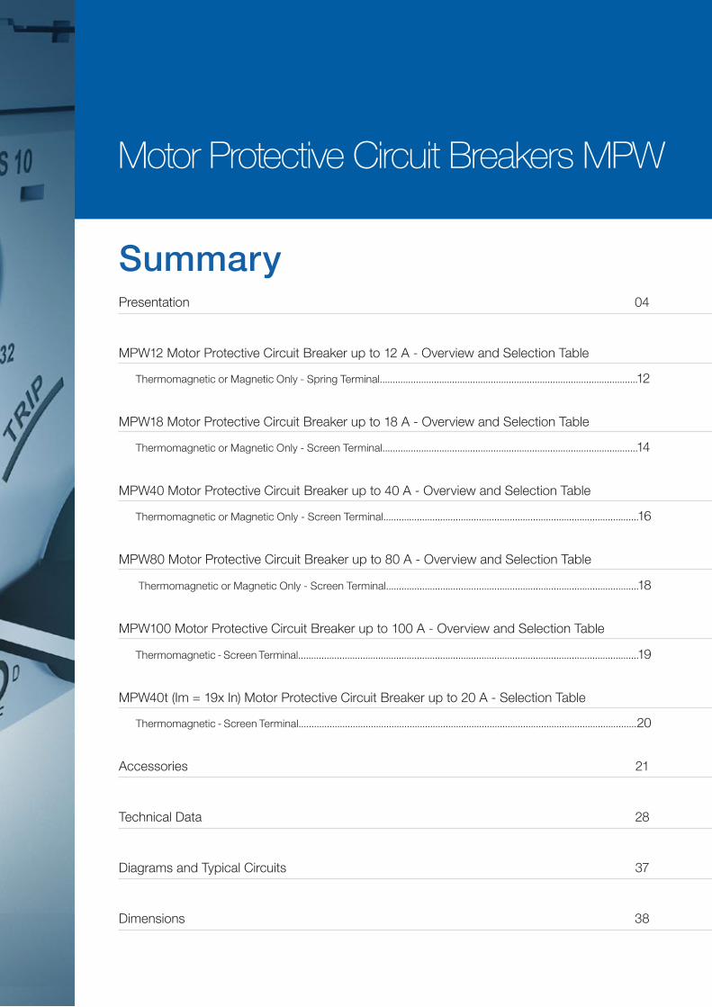
Summary
Motor Protective Circuit Breakers MPW
Presentation 04
Accessories 21
MPW12 Motor Protective Circuit Breaker up to 12 A - Overview and Selection Table
Thermomagnetic or Magnetic Only - Spring Terminal....................................................................................................12
MPW18 Motor Protective Circuit Breaker up to 18 A - Overview and Selection Table
Thermomagnetic or Magnetic Only - Screen Terminal...................................................................................................14
MPW40 Motor Protective Circuit Breaker up to 40 A - Overview and Selection Table
Thermomagnetic or Magnetic Only - Screen Terminal...................................................................................................16
MPW80 Motor Protective Circuit Breaker up to 80 A - Overview and Selection Table
Thermomagnetic or Magnetic Only - Screen Terminal..................................................................................................18
MPW100 Motor Protective Circuit Breaker up to 100 A - Overview and Selection Table
Thermomagnetic - Screen Terminal....................................................................................................................................19
MPW40t (Im = 19x In) Motor Protective Circuit Breaker up to 20 A - Selection Table
Thermomagnetic - Screen Terminal...................................................................................................................................20
Technical Data 28
Diagrams and Typical Circuits 37
Dimensions 38
www.weg.net
4 Motor Protective Circuit Breakers
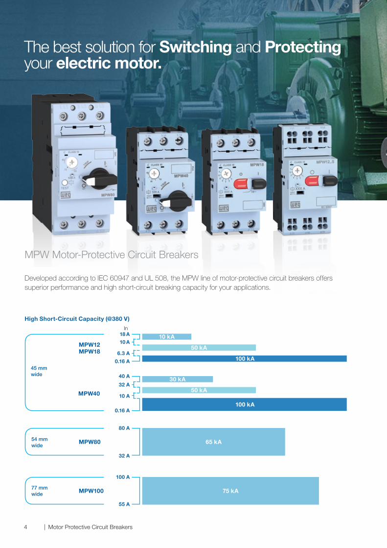
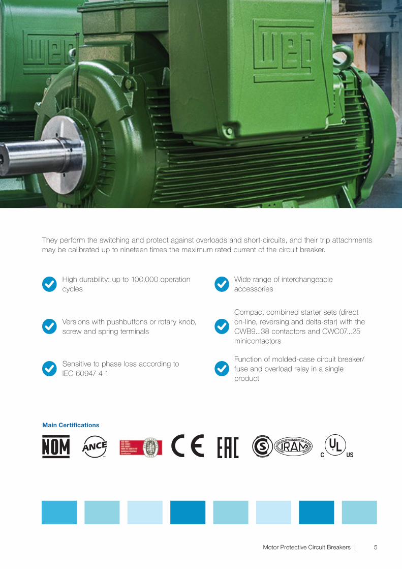
Developed according to IEC 60947 and UL 508, the MPW line of motor-protective circuit breakers offers superior performance and high short-circuit breaking capacity for your applications.
MPW Motor-Protective Circuit Breakers
High Short-Circuit Capacity (@380 V)
The best solution for Switching and Protecting your electric motor.
30 kA
50 kA
100 kA
40 A
MPW18
MPW80
MPW12
MPW40
MPW100
10 kA
50 kA
100 kA
18 A
10 A
6.3 A
0.16 A
In
45 mmwide
65 kA
80 A
32 A
54 mmwide
75 kA
100 A
55 A
77 mm wide
32 A
10 A
0.16 A
www.weg.net
5Motor Protective Circuit Breakers
They perform the switching and protect against overloads and short-circuits, and their trip attachments may be calibrated up to nineteen times the maximum rated current of the circuit breaker.
Main Certifications
Function of molded-case circuit breaker/fuse and overload relay in a single product
High durability: up to 100,000 operation cycles
Versions with pushbuttons or rotary knob, screw and spring terminals
Sensitive to phase loss according to IEC 60947-4-1
Wide range of interchangeable accessories
Compact combined starter sets (direct on-line, reversing and delta-star) with the CWB9...38 contactors and CWC07...25 minicontactors
www.weg.net
6 Motor Protective Circuit Breakers
MPW Motor-Protective Circuit Breaker
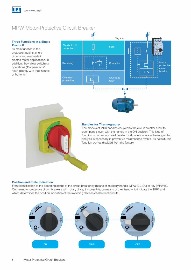
Position and State IndicationFront identification of the operating status of the circuit breaker by means of its rotary handle (MPW40...100) or key (MPW18). On the motor-protective circuit breakers with rotary drive, it is possible, by means of their handle, to indicate the TRIP, and which determines the position indication of the switching devices of electrical circuits.
Handles for ThermographyThe models of MRX handles coupled to the circuit breaker allow to open panels even with the handle in the ON position. This kind of function is commonly used on electrical panels where a thermographic analysis is necessary in preventive maintenance events. As default, this function comes disabled from the factory.
Three Functions in a Single Product!Its main function is the protection against short-circuits and overloads in electric motor applications. In addition, they allow switching operations (15 operations/hour) directly with their handle or buttons.
Manobra
Diagrams
Short-circuit protection
Fuse
Contactor
Orverloadrelay
Motorprotectivecircuitbreaker
Overload protection
I >
Switching
OFFTRIP ON
www.weg.net
7Motor Protective Circuit Breakers
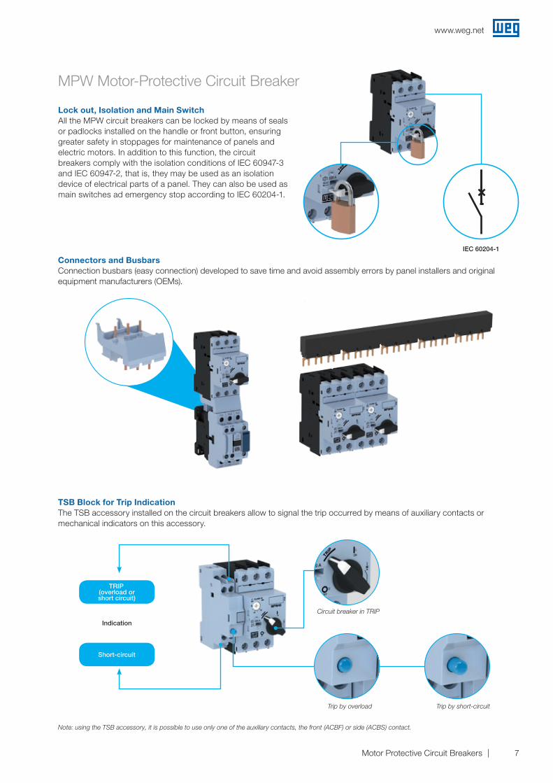
Lock out, Isolation and Main SwitchAll the MPW circuit breakers can be locked by means of seals or padlocks installed on the handle or front button, ensuring greater safety in stoppages for maintenance of panels and electric motors. In addition to this function, the circuit breakers comply with the isolation conditions of IEC 60947-3 and IEC 60947-2, that is, they may be used as an isolation device of electrical parts of a panel. They can also be used as main switches ad emergency stop according to IEC 60204-1.
Connectors and BusbarsConnection busbars (easy connection) developed to save time and avoid assembly errors by panel installers and original equipment manufacturers (OEMs).
TSB Block for Trip IndicationThe TSB accessory installed on the circuit breakers allow to signal the trip occurred by means of auxiliary contacts or mechanical indicators on this accessory.
Circuit breaker in TRIP
Trip by overload Trip by short-circuit
TRIP(overload or short circuit)
Short-circuit
IEC 60204-1
Indication
Note: using the TSB accessory, it is possible to use only one of the auxiliary contacts, the front (ACBF) or side (ACBS) contact.
MPW Motor-Protective Circuit Breaker
www.weg.net
8 Motor Protective Circuit Breakers
MPW Motor-Protective Circuit Breaker
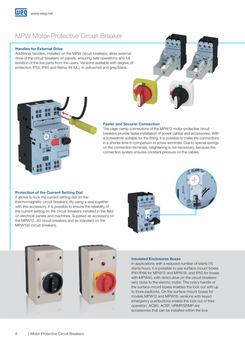
Faster and Securer ConnectionThe cage clamp connections of the MPW12 motor-protective circuit breakers provide faster installation of power cables and accessories. With a screwdriver suitable for the fitting, it is possible to make the connections in a shorter time in comparison to screw terminals. Due to special springs on the connection terminals, retightening is not necessary, because the connection system ensures constant pressure on the cables.
Protection of the Current Setting DialIt allows to lock the current setting dial on the thermomagnetic circuit breakers. By using a seal together with this accessory, it is possible to ensure the reliability of the current setting on the circuit breakers installed in the field on electrical panels and machines. Supplied as accessory on the MPW12...80 circuit breakers and as standard on the MPW100 circuit breakers.
Insulated Enclosures BoxesIn applications with a reduced number of starts (15 starts/hour), it is possible to use surface-mount boxes IP41/IP66 for MPW12 and MPW18, and IP55 for boxes with MPW40, with direct drive on the circuit breakers very close to the electric motor. The rotary handle of the surface-mount boxes enables the lock out with up to three padlocks. On the surface-mount boxes for models MPW12 and MPW18, versions with keyed emergency pushbuttons enable the lock out of their operation. ACBS, ACBF, URMP/SRMP are accessories that can be installed within the box.
Handles for External DriveAdditional handles, installed on the MPW circuit breakers, allow external drive of the circuit breakers on panels, ensuring safe operations and full isolation of the live parts from the users. Versions available with degree of protection IP55, IP65 and Nema 4X (UL), in yellow/red and grey/black.
www.weg.net
9Motor Protective Circuit Breakers
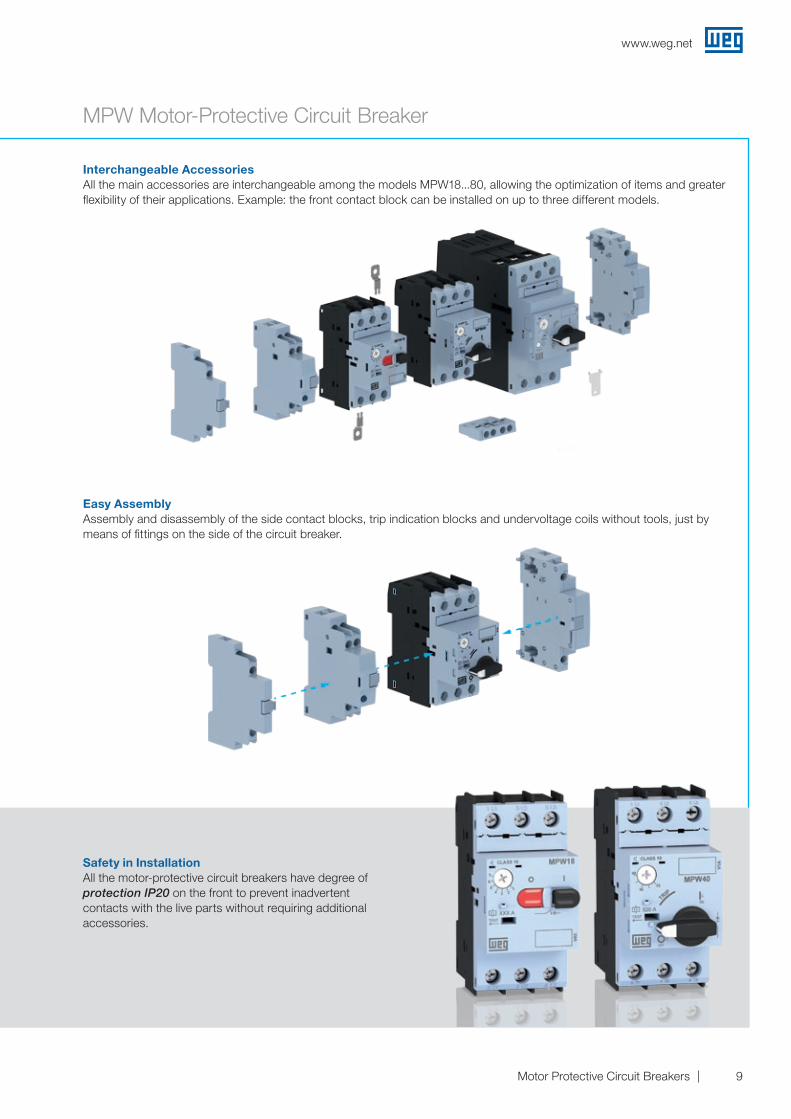
Interchangeable AccessoriesAll the main accessories are interchangeable among the models MPW18...80, allowing the optimization of items and greater flexibility of their applications. Example: the front contact block can be installed on up to three different models.
Easy AssemblyAssembly and disassembly of the side contact blocks, trip indication blocks and undervoltage coils without tools, just by means of fittings on the side of the circuit breaker.
Safety in InstallationAll the motor-protective circuit breakers have degree of protection IP20 on the front to prevent inadvertent contacts with the live parts without requiring additional accessories.
MPW Motor-Protective Circuit Breaker
www.weg.net
10 Motor Protective Circuit Breakers
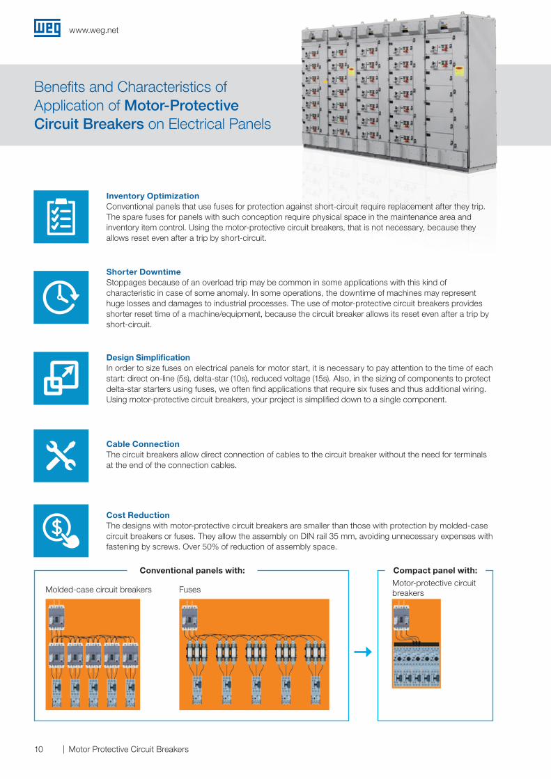
Benefits and Characteristics of Application of Motor-Protective Circuit Breakers on Electrical Panels
Cable ConnectionThe circuit breakers allow direct connection of cables to the circuit breaker without the need for terminals at the end of the connection cables.
Shorter DowntimeStoppages because of an overload trip may be common in some applications with this kind of characteristic in case of some anomaly. In some operations, the downtime of machines may represent huge losses and damages to industrial processes. The use of motor-protective circuit breakers provides shorter reset time of a machine/equipment, because the circuit breaker allows its reset even after a trip by short-circuit.
Inventory OptimizationConventional panels that use fuses for protection against short-circuit require replacement after they trip. The spare fuses for panels with such conception require physical space in the maintenance area and inventory item control. Using the motor-protective circuit breakers, that is not necessary, because they allows reset even after a trip by short-circuit.
Cost ReductionThe designs with motor-protective circuit breakers are smaller than those with protection by molded-case circuit breakers or fuses. They allow the assembly on DIN rail 35 mm, avoiding unnecessary expenses with fastening by screws. Over 50% of reduction of assembly space.
Design SimplificationIn order to size fuses on electrical panels for motor start, it is necessary to pay attention to the time of each start: direct on-line (5s), delta-star (10s), reduced voltage (15s). Also, in the sizing of components to protect delta-star starters using fuses, we often find applications that require six fuses and thus additional wiring. Using motor-protective circuit breakers, your project is simplified down to a single component.
Molded-case circuit breakers Fuses Motor-protective circuit breakers
Conventional panels with: Compact panel with:
www.weg.net
11Motor Protective Circuit Breakers
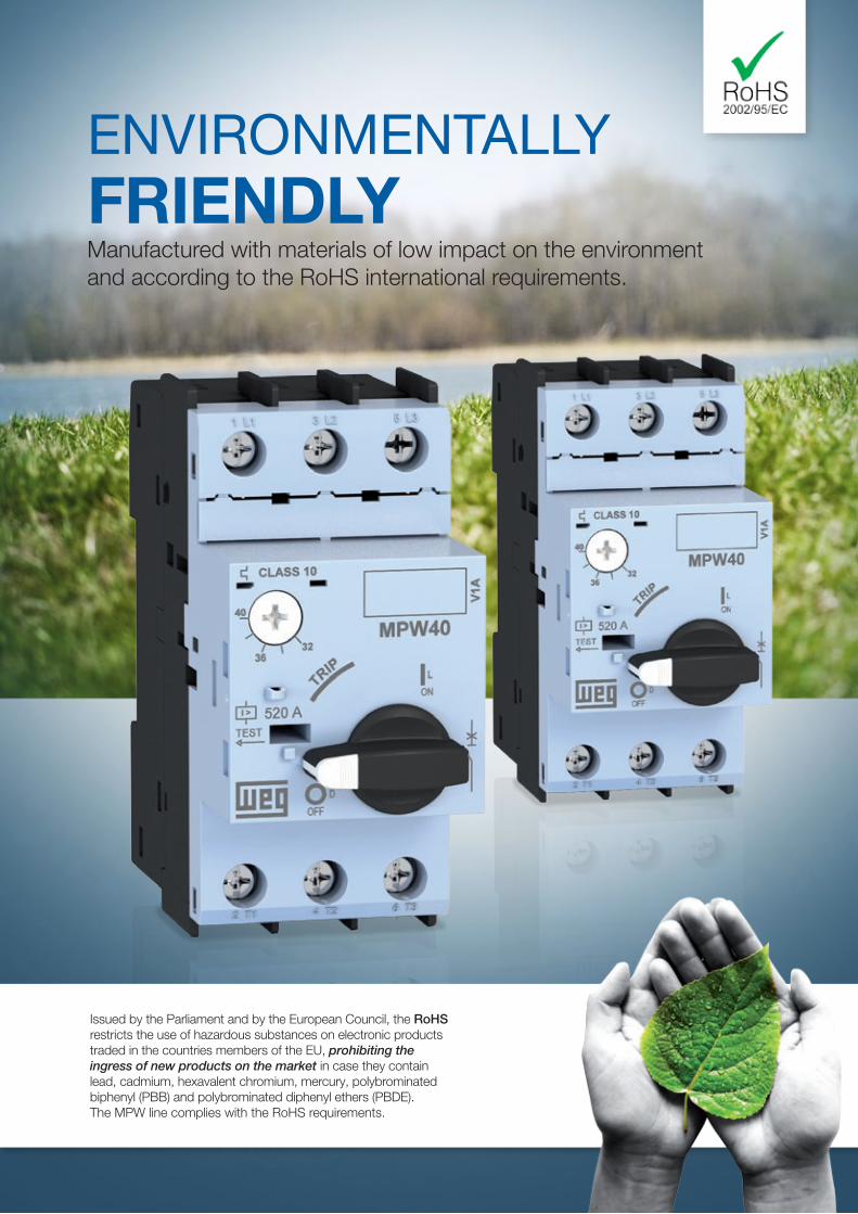
ENVIRONMENTALLY FRIENDLYManufactured with materials of low impact on the environment and according to the RoHS international requirements.
Issued by the Parliament and by the European Council, the RoHS restricts the use of hazardous substances on electronic products traded in the countries members of the EU, prohibiting the ingress of new products on the market in case they contain lead, cadmium, hexavalent chromium, mercury, polybrominated biphenyl (PBB) and polybrominated diphenyl ethers (PBDE).The MPW line complies with the RoHS requirements.
www.weg.net
12 Motor Protective Circuit Breakers
7
4
1
6
2
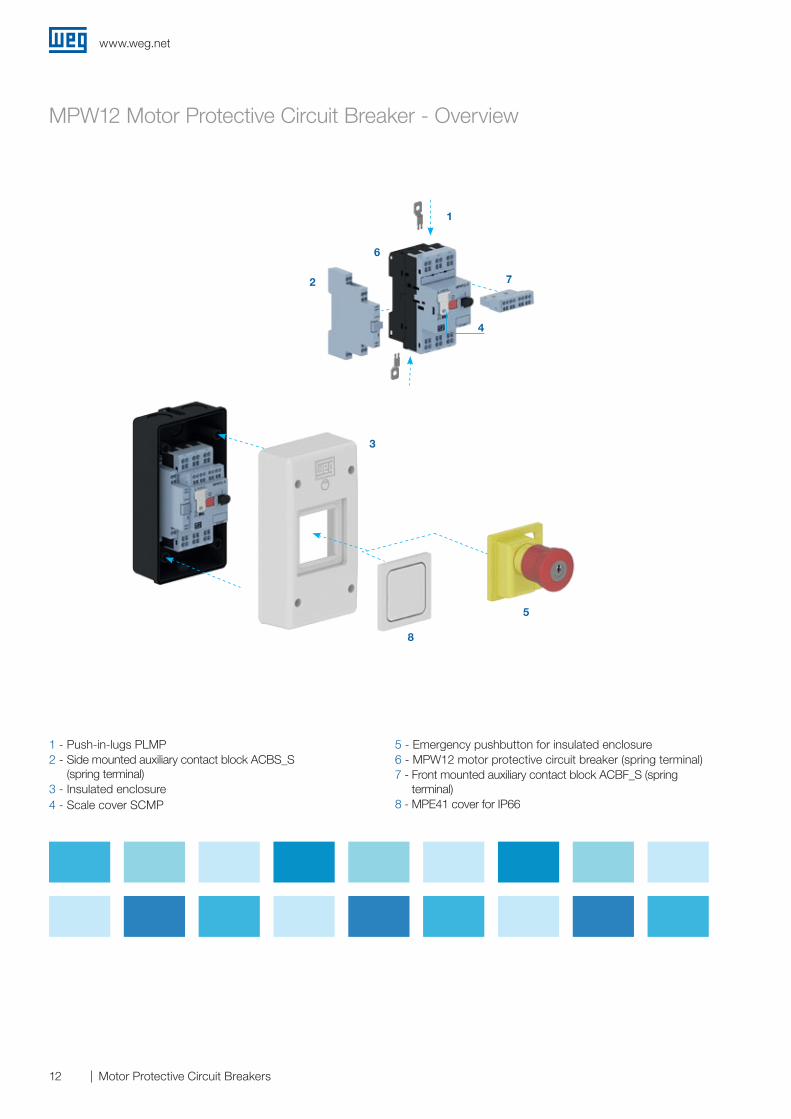
MPW12 Motor Protective Circuit Breaker - Overview
5
8
3
1 - Push-in-lugs PLMP2 - Side mounted auxiliary contact block ACBS_S
(spring terminal)3 - Insulated enclosure4 - Scale cover SCMP
5 - Emergency pushbutton for insulated enclosure6 - MPW12 motor protective circuit breaker (spring terminal)7 - Front mounted auxiliary contact block ACBF_S (spring
terminal)8 - MPE41 cover for IP66
www.weg.net
13Motor Protective Circuit Breakers
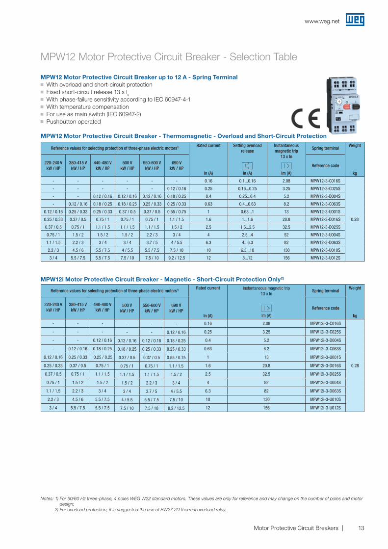
MPW12 Motor Protective Circuit Breaker - Selection Table
MPW12 Motor Protective Circuit Breaker up to 12 A - Spring Terminal J With overload and short-circuit protection J Fixed short-circuit release 13 x lu J With phase-failure sensitivity according to IEC 60947-4-1 J With temperature compensation J For use as main switch (IEC 60947-2) J Pushbutton operated
MPW12i Motor Protective Circuit Breaker - Magnetic - Short-Circuit Protection Only2)
MPW12 Motor Protective Circuit Breaker - Thermomagnetic - Overload and Short-Circuit Protection
Notes: 1) For 50/60 Hz three-phase, 4 poles WEG W22 standard motors. These values are only for reference and may change on the number of poles and motor design;
2) For overload protection, it is suggested the use of RW27-2D thermal overload relay.
Reference values for selecting protection of three-phase electric motors1) Rated current
In (A)
Setting overload release
In (A)
Instantaneous magnetic trip
13 x In
Im (A)
Spring terminalWeight
kg
220-240 VkW / HP
380-415 VkW / HP
440-480 VkW / HP
500 VkW / HP
550-600 VkW / HP
690 VkW / HP
Reference code
- - - - - - 0.16 0.1...0.16 2.08 MPW12-3-C016S
0.28
- - - - - 0.12 / 0.16 0.25 0.16...0.25 3.25 MPW12-3-C025S
- - 0.12 / 0.16 0.12 / 0.16 0.12 / 0.16 0.18 / 0.25 0.4 0.25...0.4 5.2 MPW12-3-D004S
- 0.12 / 0.16 0.18 / 0.25 0.18 / 0.25 0.25 / 0.33 0.25 / 0.33 0.63 0.4...0.63 8.2 MPW12-3-C063S
0.12 / 0.16 0.25 / 0.33 0.25 / 0.33 0.37 / 0.5 0.37 / 0.5 0.55 / 0.75 1 0.63...1 13 MPW12-3-U001S
0.25 / 0.33 0.37 / 0.5 0.75 / 1 0.75 / 1 0.75 / 1 1.1 / 1.5 1.6 1...1.6 20.8 MPW12-3-D016S
0.37 / 0.5 0.75 / 1 1.1 / 1.5 1.1 / 1.5 1.1 / 1.5 1.5 / 2 2.5 1.6...2.5 32.5 MPW12-3-D025S
0.75 / 1 1.5 / 2 1.5 / 2 1.5 / 2 2.2 / 3 3 / 4 4 2.5...4 52 MPW12-3-U004S
1.1 / 1.5 2.2 / 3 3 / 4 3 / 4 3.7 / 5 4 / 5.5 6.3 4...6.3 82 MPW12-3-D063S
2.2 / 3 4.5 / 6 5.5 / 7.5 4 / 5.5 5.5 / 7.5 7.5 / 10 10 6.3...10 130 MPW12-3-U010S
3 / 4 5.5 / 7.5 5.5 / 7.5 7.5 / 10 7.5 / 10 9.2 / 12.5 12 8...12 156 MPW12-3-U012S
Reference values for selecting protection of three-phase electric motors1) Rated current
In (A)
Instantaneous magnetic trip13 x In
Im (A)
Spring terminalWeight
kg
220-240 VkW / HP
380-415 VkW / HP
440-480 VkW / HP
500 VkW / HP
550-600 VkW / HP
690 VkW / HP
Reference code
- - - - - - 0.16 2.08 MPW12i-3-C016S
0.28
- - - - - 0.12 / 0.16 0.25 3.25 MPW12i-3-C025S
- - 0.12 / 0.16 0.12 / 0.16 0.12 / 0.16 0.18 / 0.25 0.4 5.2 MPW12i-3-D004S
- 0.12 / 0.16 0.18 / 0.25 0.18 / 0.25 0.25 / 0.33 0.25 / 0.33 0.63 8.2 MPW12i-3-C063S
0.12 / 0.16 0.25 / 0.33 0.25 / 0.25 0.37 / 0.5 0.37 / 0.5 0.55 / 0.75 1 13 MPW12i-3-U001S
0.25 / 0.33 0.37 / 0.5 0.75 / 1 0.75 / 1 0.75 / 1 1.1 / 1.5 1.6 20.8 MPW12i-3-D016S
0.37 / 0.5 0.75 / 1 1.1 / 1.5 1.1 / 1.5 1.1 / 1.5 1.5 / 2 2.5 32.5 MPW12i-3-D025S
0.75 / 1 1.5 / 2 1.5 / 2 1.5 / 2 2.2 / 3 3 / 4 4 52 MPW12i-3-U004S
1.1 / 1.5 2.2 / 3 3 / 4 3 / 4 3.7 / 5 4 / 5.5 6.3 82 MPW12i-3-D063S
2.2 / 3 4.5 / 6 5.5 / 7.5 4 / 5.5 5.5 / 7.5 7.5 / 10 10 130 MPW12i-3-U010S
3 / 4 5.5 / 7.5 5.5 / 7.5 7.5 / 10 7.5 / 10 9.2 / 12.5 12 156 MPW12i-3-U012S
www.weg.net
14 Motor Protective Circuit Breakers
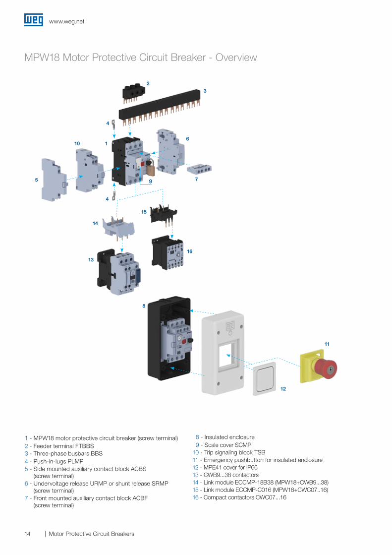
1 - MPW18 motor protective circuit breaker (screw terminal)2 - Feeder terminal FTBBS3 - Three-phase busbars BBS4 - Push-in-lugs PLMP5 - Side mounted auxiliary contact block ACBS
(screw terminal)6 - Undervoltage release URMP or shunt release SRMP
(screw terminal)7 - Front mounted auxiliary contact block ACBF
(screw terminal)
8 - Insulated enclosure 9 - Scale cover SCMP10 - Trip signaling block TSB 11 - Emergency pushbutton for insulated enclosure12 - MPE41 cover for IP66 13 - CWB9...38 contactors14 - Link module ECCMP-18B38 (MPW18+CWB9...38)15 - Link module ECCMP-C016 (MPW18+CWC07..16)16 - Compact contactors CWC07...16
MPW18 Motor Protective Circuit Breaker - Overview
23
61
4
4
10
5 7
13
14
15
16
11
12
8
9
www.weg.net
15Motor Protective Circuit Breakers
Reference values for selecting protection of three-phase electric motors1) Rated current
In (A)
Setting overload release
In (A)
Instantaneous magnetic trip
13 x In
Im (A)
Screw terminalWeight
kg
220-240 VkW / HP
380-415 VkW / HP
440-480 VkW / HP
500 V kW / HP
550-600 V kW / HP
690 V kW / HP
Reference code
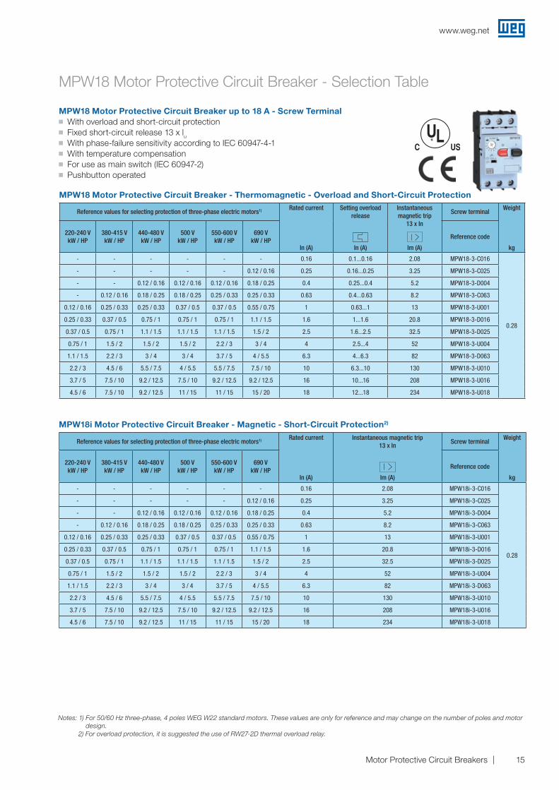
- - - - - - 0.16 0.1...0.16 2.08 MPW18-3-C016
0.28
- - - - - 0.12 / 0.16 0.25 0.16...0.25 3.25 MPW18-3-C025
- - 0.12 / 0.16 0.12 / 0.16 0.12 / 0.16 0.18 / 0.25 0.4 0.25...0.4 5.2 MPW18-3-D004
- 0.12 / 0.16 0.18 / 0.25 0.18 / 0.25 0.25 / 0.33 0.25 / 0.33 0.63 0.4...0.63 8.2 MPW18-3-C063
0.12 / 0.16 0.25 / 0.33 0.25 / 0.33 0.37 / 0.5 0.37 / 0.5 0.55 / 0.75 1 0.63...1 13 MPW18-3-U001
0.25 / 0.33 0.37 / 0.5 0.75 / 1 0.75 / 1 0.75 / 1 1.1 / 1.5 1.6 1...1.6 20.8 MPW18-3-D016
0.37 / 0.5 0.75 / 1 1.1 / 1.5 1.1 / 1.5 1.1 / 1.5 1.5 / 2 2.5 1.6...2.5 32.5 MPW18-3-D025
0.75 / 1 1.5 / 2 1.5 / 2 1.5 / 2 2.2 / 3 3 / 4 4 2.5...4 52 MPW18-3-U004
1.1 / 1.5 2.2 / 3 3 / 4 3 / 4 3.7 / 5 4 / 5.5 6.3 4...6.3 82 MPW18-3-D063
2.2 / 3 4.5 / 6 5.5 / 7.5 4 / 5.5 5.5 / 7.5 7.5 / 10 10 6.3...10 130 MPW18-3-U010
3.7 / 5 7.5 / 10 9.2 / 12.5 7.5 / 10 9.2 / 12.5 9.2 / 12.5 16 10...16 208 MPW18-3-U016
4.5 / 6 7.5 / 10 9.2 / 12.5 11 / 15 11 / 15 15 / 20 18 12...18 234 MPW18-3-U018
MPW18 Motor Protective Circuit Breaker - Selection Table
MPW18 Motor Protective Circuit Breaker up to 18 A - Screw Terminal J With overload and short-circuit protection J Fixed short-circuit release 13 x lu J With phase-failure sensitivity according to IEC 60947-4-1 J With temperature compensation J For use as main switch (IEC 60947-2) J Pushbutton operated
MPW18i Motor Protective Circuit Breaker - Magnetic - Short-Circuit Protection2)
MPW18 Motor Protective Circuit Breaker - Thermomagnetic - Overload and Short-Circuit Protection
Notes: 1) For 50/60 Hz three-phase, 4 poles WEG W22 standard motors. These values are only for reference and may change on the number of poles and motor design.
2) For overload protection, it is suggested the use of RW27-2D thermal overload relay.
Reference values for selecting protection of three-phase electric motors1) Rated current
In (A)
Instantaneous magnetic trip13 x In
Im (A)
Screw terminalWeight
kg
220-240 VkW / HP
380-415 VkW / HP
440-480 VkW / HP
500 V kW / HP
550-600 V kW / HP
690 V kW / HP
Reference code
- - - - - - 0.16 2.08 MPW18i-3-C016
0.28
- - - - - 0.12 / 0.16 0.25 3.25 MPW18i-3-C025
- - 0.12 / 0.16 0.12 / 0.16 0.12 / 0.16 0.18 / 0.25 0.4 5.2 MPW18i-3-D004
- 0.12 / 0.16 0.18 / 0.25 0.18 / 0.25 0.25 / 0.33 0.25 / 0.33 0.63 8.2 MPW18i-3-C063
0.12 / 0.16 0.25 / 0.33 0.25 / 0.33 0.37 / 0.5 0.37 / 0.5 0.55 / 0.75 1 13 MPW18i-3-U001
0.25 / 0.33 0.37 / 0.5 0.75 / 1 0.75 / 1 0.75 / 1 1.1 / 1.5 1.6 20.8 MPW18i-3-D016
0.37 / 0.5 0.75 / 1 1.1 / 1.5 1.1 / 1.5 1.1 / 1.5 1.5 / 2 2.5 32.5 MPW18i-3-D025
0.75 / 1 1.5 / 2 1.5 / 2 1.5 / 2 2.2 / 3 3 / 4 4 52 MPW18i-3-U004
1.1 / 1.5 2.2 / 3 3 / 4 3 / 4 3.7 / 5 4 / 5.5 6.3 82 MPW18i-3-D063
2.2 / 3 4.5 / 6 5.5 / 7.5 4 / 5.5 5.5 / 7.5 7.5 / 10 10 130 MPW18i-3-U010
3.7 / 5 7.5 / 10 9.2 / 12.5 7.5 / 10 9.2 / 12.5 9.2 / 12.5 16 208 MPW18i-3-U016
4.5 / 6 7.5 / 10 9.2 / 12.5 11 / 15 11 / 15 15 / 20 18 234 MPW18i-3-U018
www.weg.net
16 Motor Protective Circuit Breakers
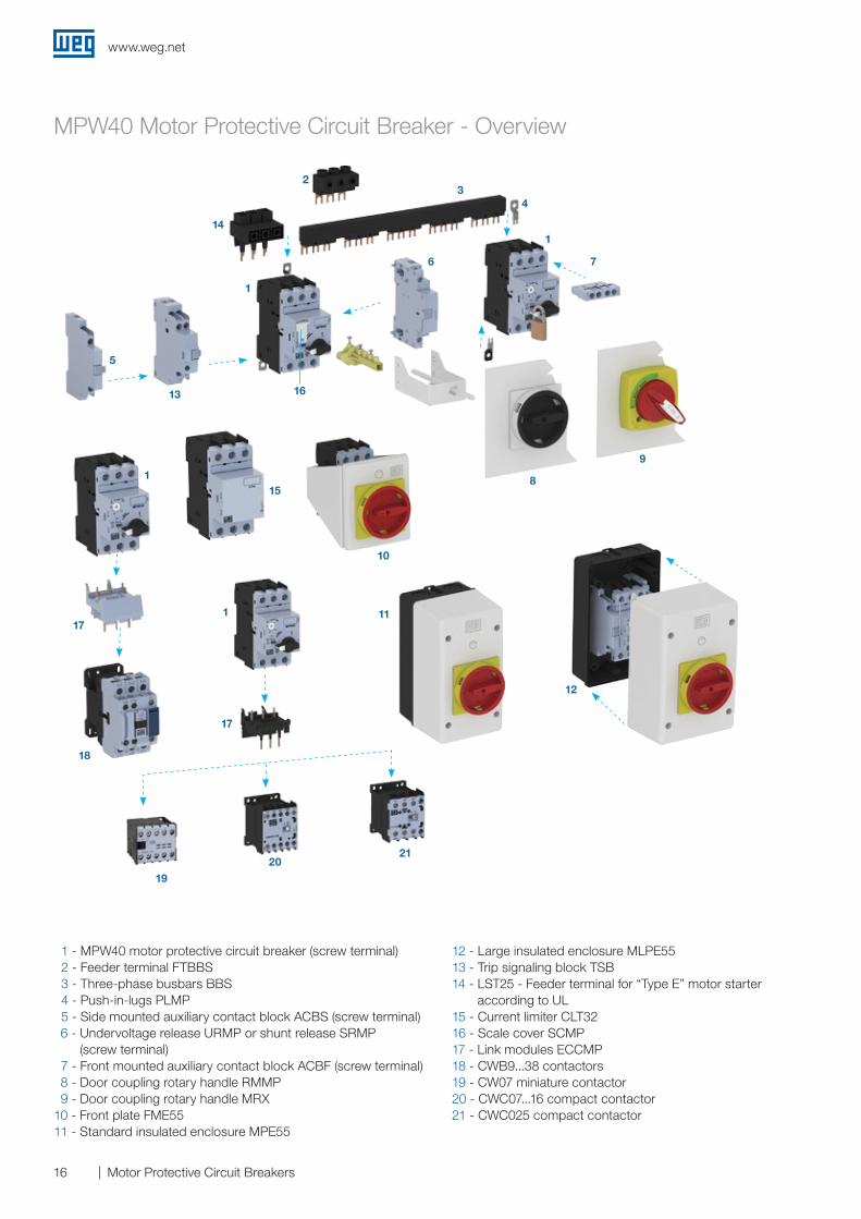
MPW40 Motor Protective Circuit Breaker - Overview
1 - MPW40 motor protective circuit breaker (screw terminal) 2 - Feeder terminal FTBBS 3 - Three-phase busbars BBS 4 - Push-in-lugs PLMP 5 - Side mounted auxiliary contact block ACBS (screw terminal) 6 - Undervoltage release URMP or shunt release SRMP
(screw terminal) 7 - Front mounted auxiliary contact block ACBF (screw terminal) 8 - Door coupling rotary handle RMMP 9 - Door coupling rotary handle MRX10 - Front plate FME5511 - Standard insulated enclosure MPE55
12 - Large insulated enclosure MLPE5513 - Trip signaling block TSB14 - LST25 - Feeder terminal for “Type E” motor starter
according to UL 15 - Current limiter CLT3216 - Scale cover SCMP17 - Link modules ECCMP18 - CWB9...38 contactors19 - CW07 miniature contactor20 - CWC07...16 compact contactor21 - CWC025 compact contactor
32
4
14
1
17
18
5
13 16
1
17
1
7
9
8
10
6
1
11
15
2120
19
12
www.weg.net
17Motor Protective Circuit Breakers
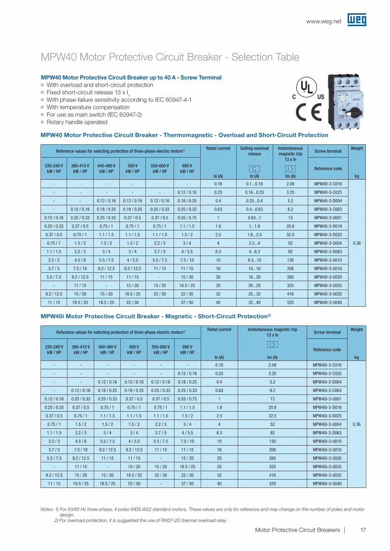
MPW40 Motor Protective Circuit Breaker up to 40 A - Screw Terminal J With overload and short-circuit protection J Fixed short-circuit release 13 x Iu J With phase-failure sensitivity according to IEC 60947-4-1 J With temperature compensation J For use as main switch (IEC 60947-2) J Rotary handle operated
Reference values for selecting protection of three-phase electric motors1) Rated current
In (A)
Instantaneous magnetic trip13 x In
Im (A)
Screw terminalWeight
kg
220-240 VkW / HP
380-415 VkW / HP
440-480 VkW / HP
500 V kW / HP
550-600 V kW / HP
690 V kW / HP
Reference code
- - - - - - 0.16 2.08 MPW40i-3-C016
0.36
- - - - - 0.12 / 0.16 0.25 3.25 MPW40i-3-C025
- - 0.12 / 0.16 0.12 / 0.16 0.12 / 0.16 0.18 / 0.25 0.4 5.2 MPW40i-3-D004
- 0.12 / 0.16 0.18 / 0.25 0.18 / 0.25 0.25 / 0.33 0.25 / 0.33 0.63 8.2 MPW40i-3-C063
0.12 / 0.16 0.25 / 0.33 0.25 / 0.33 0.37 / 0.5 0.37 / 0.5 0.55 / 0.75 1 13 MPW40i-3-U001
0.25 / 0.33 0.37 / 0.5 0.75 / 1 0.75 / 1 0.75 / 1 1.1 / 1.5 1.6 20.8 MPW40i-3-D016
0.37 / 0.5 0.75 / 1 1.1 / 1.5 1.1 / 1.5 1.1 / 1.5 1.5 / 2 2.5 32.5 MPW40i-3-D025
0.75 / 1 1.5 / 2 1.5 / 2 1.5 / 2 2.2 / 3 3 / 4 4 52 MPW40i-3-U004
1.1 / 1.5 2.2 / 3 3 / 4 3 / 4 3.7 / 5 4 / 5.5 6.3 82 MPW40i-3-D063
2.2 / 3 4.5 / 6 5.5 / 7.5 4 / 5.5 5.5 / 7.5 7.5 / 10 10 130 MPW40i-3-U010
3.7 / 5 7.5 / 10 9.2 / 12.5 9.2 / 12.5 11 / 15 11 / 15 16 208 MPW40i-3-U016
5.5 / 7.5 9.2 / 12.5 11 / 15 11 / 15 - 15 / 20 20 260 MPW40i-3-U020
- 11 / 15 - 15 / 20 15 / 20 18.5 / 25 25 325 MPW40i-3-U025
9.2 / 12.5 15 / 20 15 / 20 18.5 / 25 22 / 30 22 / 30 32 416 MPW40i-3-U032
11 / 15 18.5 / 25 18.5 / 25 22 / 30 - 37 / 50 40 520 MPW40i-3-U040
Reference values for selecting protection of three-phase electric motors1) Rated current
In (A)
Setting overload release
In (A)
Instantaneous magnetic trip
13 x In
Im (A)
Screw terminalWeight
kg
220-240 VkW / HP
380-415 VkW / HP
440-480 VkW / HP
500 V kW / HP
550-600 V kW / HP
690 V kW / HP
Reference code
- - - - - - 0.16 0.1...0.16 2.08 MPW40-3-C016
0.36
- - - - - 0.12 / 0.16 0.25 0.16...0.25 3.25 MPW40-3-C025
- - 0.12 / 0.16 0.12 / 0.16 0.12 / 0.16 0.18 / 0.25 0.4 0.25...0.4 5.2 MPW40-3-D004
- 0.12 / 0.16 0.18 / 0.25 0.18 / 0.25 0.25 / 0.33 0.25 / 0.33 0.63 0.4...0.63 8.2 MPW40-3-C063
0.12 / 0.16 0.25 / 0.33 0.25 / 0.33 0.37 / 0.5 0.37 / 0.5 0.55 / 0.75 1 0.63...1 13 MPW40-3-U001
0.25 / 0.33 0.37 / 0.5 0.75 / 1 0.75 / 1 0.75 / 1 1.1 / 1.5 1.6 1...1.6 20.8 MPW40-3-D016
0.37 / 0.5 0.75 / 1 1.1 / 1.5 1.1 / 1.5 1.1 / 1.5 1.5 / 2 2.5 1.6...2.5 32.5 MPW40-3-D025
0.75 / 1 1.5 / 2 1.5 / 2 1.5 / 2 2.2 / 3 3 / 4 4 2.5...4 52 MPW40-3-U004
1.1 / 1.5 2.2 / 3 3 / 4 3 / 4 3.7 / 5 4 / 5.5 6.3 4...6.3 82 MPW40-3-D063
2.2 / 3 4.5 / 6 5.5 / 7.5 4 / 5.5 5.5 / 7.5 7.5 / 10 10 6.3...10 130 MPW40-3-U010
3.7 / 5 7.5 / 10 9.2 / 12.5 9.2 / 12.5 11 / 15 11 / 15 16 10...16 208 MPW40-3-U016
5.5 / 7.5 9.2 / 12.5 11 / 15 11 / 15 - 15 / 20 20 16...20 260 MPW40-3-U020
- 11 / 15 - 15 / 20 15 / 20 18.5 / 25 25 20...25 325 MPW40-3-U025
9.2 / 12.5 15 / 20 15 / 20 18.5 / 25 22 / 30 22 / 30 32 25...32 416 MPW40-3-U032
11 / 15 18.5 / 25 18.5 / 25 22 / 30 - 37 / 50 40 32...40 520 MPW40-3-U040
MPW40 Motor Protective Circuit Breaker - Selection Table
MPW40 Motor Protective Circuit Breaker - Thermomagnetic - Overload and Short-Circuit Protection
MPW40i Motor Protective Circuit Breaker - Magnetic - Short-Circuit Protection2)
Notes: 1) For 50/60 Hz three-phase, 4 poles WEG W22 standard motors. These values are only for reference and may change on the number of poles and motor design.
2) For overload protection, it is suggested the use of RW27-2D thermal overload relay.
www.weg.net
18 Motor Protective Circuit Breakers
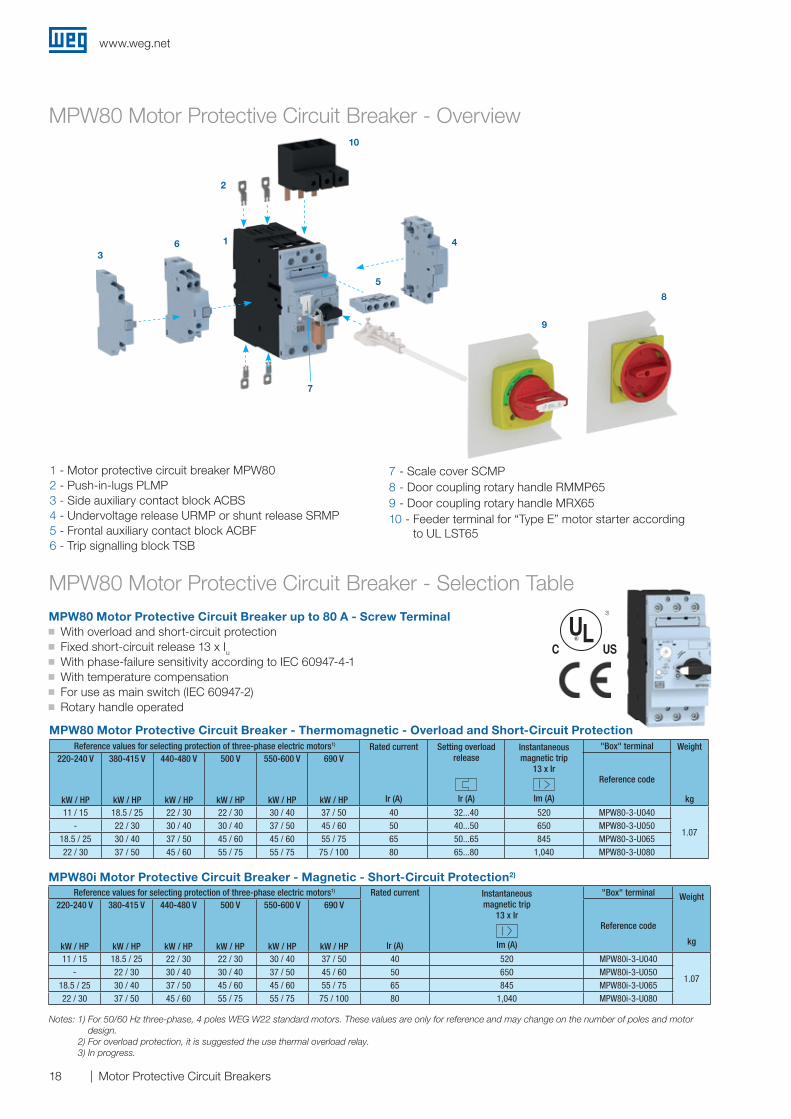
MPW80 Motor Protective Circuit Breaker up to 80 A - Screw Terminal J With overload and short-circuit protection J Fixed short-circuit release 13 x Iu J With phase-failure sensitivity according to IEC 60947-4-1 J With temperature compensation J For use as main switch (IEC 60947-2) J Rotary handle operated
MPW80 Motor Protective Circuit Breaker - Thermomagnetic - Overload and Short-Circuit Protection
MPW80i Motor Protective Circuit Breaker - Magnetic - Short-Circuit Protection2)
Reference values for selecting protection of three-phase electric motors1) Rated current
Ir (A)
Instantaneousmagnetic trip
13 x Ir
Im (A)
"Box" terminal Weight
kg
220-240 V
kW / HP
380-415 V
kW / HP
440-480 V
kW / HP
500 V
kW / HP
550-600 V
kW / HP
690 V
kW / HP
Reference code
11 / 15 18.5 / 25 22 / 30 22 / 30 30 / 40 37 / 50 40 520 MPW80i-3-U040
1.07- 22 / 30 30 / 40 30 / 40 37 / 50 45 / 60 50 650 MPW80i-3-U050
18.5 / 25 30 / 40 37 / 50 45 / 60 45 / 60 55 / 75 65 845 MPW80i-3-U06522 / 30 37 / 50 45 / 60 55 / 75 55 / 75 75 / 100 80 1,040 MPW80i-3-U080
Notes: 1) For 50/60 Hz three-phase, 4 poles WEG W22 standard motors. These values are only for reference and may change on the number of poles and motor design.
2) For overload protection, it is suggested the use thermal overload relay.3) In progress.
3)
Reference values for selecting protection of three-phase electric motors1) Rated current
Ir (A)
Setting overload release
Ir (A)
Instantaneousmagnetic trip
13 x Ir
Im (A)
"Box" terminal Weight
kg
220-240 V
kW / HP
380-415 V
kW / HP
440-480 V
kW / HP
500 V
kW / HP
550-600 V
kW / HP
690 V
kW / HP
Reference code
11 / 15 18.5 / 25 22 / 30 22 / 30 30 / 40 37 / 50 40 32...40 520 MPW80-3-U040
1.07- 22 / 30 30 / 40 30 / 40 37 / 50 45 / 60 50 40...50 650 MPW80-3-U050
18.5 / 25 30 / 40 37 / 50 45 / 60 45 / 60 55 / 75 65 50...65 845 MPW80-3-U06522 / 30 37 / 50 45 / 60 55 / 75 55 / 75 75 / 100 80 65...80 1,040 MPW80-3-U080
MPW80 Motor Protective Circuit Breaker - Selection Table
MPW80 Motor Protective Circuit Breaker - Overview
1 - Motor protective circuit breaker MPW802 - Push-in-lugs PLMP3 - Side auxiliary contact block ACBS4 - Undervoltage release URMP or shunt release SRMP5 - Frontal auxiliary contact block ACBF6 - Trip signalling block TSB
7 - Scale cover SCMP8 - Door coupling rotary handle RMMP659 - Door coupling rotary handle MRX6510 - Feeder terminal for “Type E” motor starter according
to UL LST65
10
2
36
7
8
9
4
5
1
www.weg.net
19Motor Protective Circuit Breakers
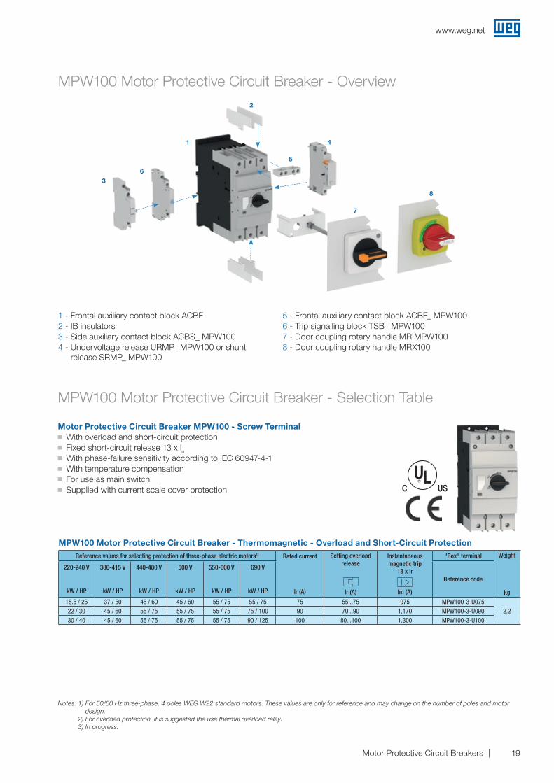
Motor Protective Circuit Breaker MPW100 - Screw Terminal J With overload and short-circuit protection J Fixed short-circuit release 13 x lu J With phase-failure sensitivity according to IEC 60947-4-1 J With temperature compensation J For use as main switch J Supplied with current scale cover protection
Reference values for selecting protection of three-phase electric motors1) Rated current
Ir (A)
Setting overload release
Ir (A)
Instantaneousmagnetic trip
13 x Ir
Im (A)
"Box" terminal Weight
kg
220-240 V
kW / HP
380-415 V
kW / HP
440-480 V
kW / HP
500 V
kW / HP
550-600 V
kW / HP
690 V
kW / HP
Reference code
18.5 / 25 37 / 50 45 / 60 45 / 60 55 / 75 55 / 75 75 55...75 975 MPW100-3-U0752.222 / 30 45 / 60 55 / 75 55 / 75 55 / 75 75 / 100 90 70...90 1,170 MPW100-3-U090
30 / 40 45 / 60 55 / 75 55 / 75 55 / 75 90 / 125 100 80...100 1,300 MPW100-3-U100
MPW100 Motor Protective Circuit Breaker - Thermomagnetic - Overload and Short-Circuit Protection
MPW100 Motor Protective Circuit Breaker - Selection Table
MPW100 Motor Protective Circuit Breaker - Overview
36
1
2
5
4
7
8
1 - Frontal auxiliary contact block ACBF2 - IB insulators3 - Side auxiliary contact block ACBS_ MPW1004 - Undervoltage release URMP_ MPW100 or shunt
release SRMP_ MPW100
5 - Frontal auxiliary contact block ACBF_ MPW1006 - Trip signalling block TSB_ MPW1007 - Door coupling rotary handle MR MPW1008 - Door coupling rotary handle MRX100
Notes: 1) For 50/60 Hz three-phase, 4 poles WEG W22 standard motors. These values are only for reference and may change on the number of poles and motor design.
2) For overload protection, it is suggested the use thermal overload relay.3) In progress.
www.weg.net
20 Motor Protective Circuit Breakers
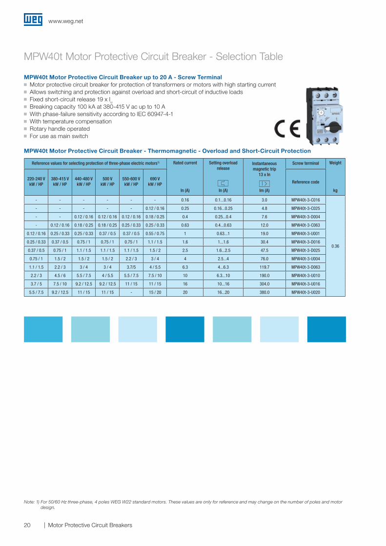
MPW40t Motor Protective Circuit Breaker - Selection Table
MPW40t Motor Protective Circuit Breaker up to 20 A - Screw Terminal J Motor protective circuit breaker for protection of transformers or motors with high starting current J Allows switching and protection against overload and short-circuit of inductive loads J Fixed short-circuit release 19 x Iu J Breaking capacity 100 kA at 380-415 V ac up to 10 A J With phase-failure sensitivity according to IEC 60947-4-1 J With temperature compensation J Rotary handle operated J For use as main switch
Note: 1) For 50/60 Hz three-phase, 4 poles WEG W22 standard motors. These values are only for reference and may change on the number of poles and motor design.
MPW40t Motor Protective Circuit Breaker - Thermomagnetic - Overload and Short-Circuit Protection
Reference values for selecting protection of three-phase electric motors1) Rated current
In (A)
Setting overload release
In (A)
Instantaneous magnetic trip
13 x In
Im (A)
Screw terminal Weight
kg
220-240 VkW / HP
380-415 VkW / HP
440-480 VkW / HP
500 VkW / HP
550-600 VkW / HP
690 V kW / HP Reference code
- - - - - - 0.16 0.1...0.16 3.0 MPW40t-3-C016
0.36
- - - - - 0.12 / 0.16 0.25 0.16...0.25 4.8 MPW40t-3-C025
- - 0.12 / 0.16 0.12 / 0.16 0.12 / 0.16 0.18 / 0.25 0.4 0.25...0.4 7.6 MPW40t-3-D004
- 0.12 / 0.16 0.18 / 0.25 0.18 / 0.25 0.25 / 0.33 0.25 / 0.33 0.63 0.4...0.63 12.0 MPW40t-3-C063
0.12 / 0.16 0.25 / 0.33 0.25 / 0.33 0.37 / 0.5 0.37 / 0.5 0.55 / 0.75 1 0.63...1 19.0 MPW40t-3-U001
0.25 / 0.33 0.37 / 0.5 0.75 / 1 0.75 / 1 0.75 / 1 1.1 / 1.5 1.6 1...1.6 30.4 MPW40t-3-D016
0.37 / 0.5 0.75 / 1 1.1 / 1.5 1.1 / 1.5 1.1 / 1.5 1.5 / 2 2.5 1.6...2.5 47.5 MPW40t-3-D025
0.75 / 1 1.5 / 2 1.5 / 2 1.5 / 2 2.2 / 3 3 / 4 4 2.5...4 76.0 MPW40t-3-U004
1.1 / 1.5 2.2 / 3 3 / 4 3 / 4 3.7/5 4 / 5.5 6.3 4...6.3 119.7 MPW40t-3-D063
2.2 / 3 4.5 / 6 5.5 / 7.5 4 / 5.5 5.5 / 7.5 7.5 / 10 10 6.3...10 190.0 MPW40t-3-U010
3.7 / 5 7.5 / 10 9.2 / 12.5 9.2 / 12.5 11 / 15 11 / 15 16 10...16 304.0 MPW40t-3-U016
5.5 / 7.5 9.2 / 12.5 11 / 15 11 / 15 - 15 / 20 20 16...20 380.0 MPW40t-3-U020
www.weg.net
21Motor Protective Circuit Breakers
Accessories
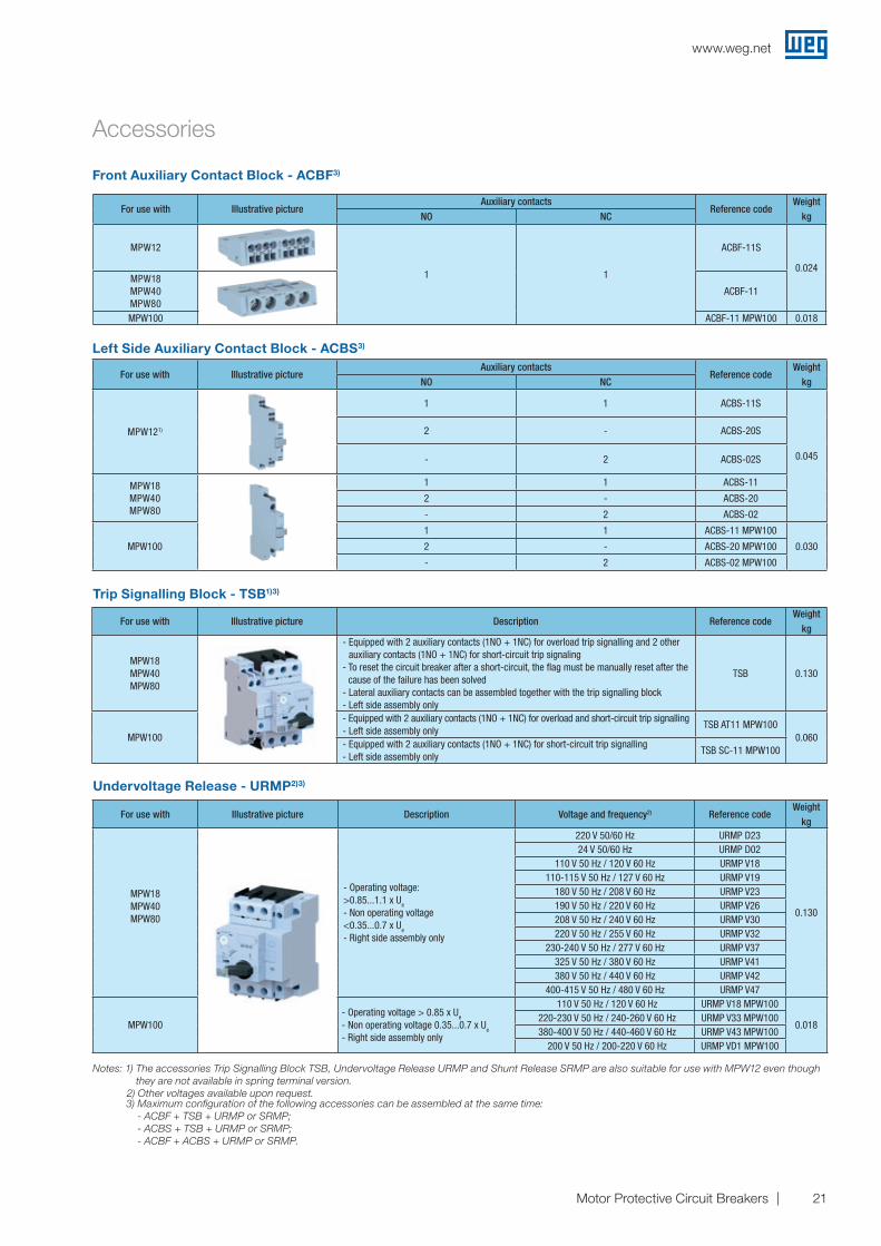
Front Auxiliary Contact Block - ACBF3)
Left Side Auxiliary Contact Block - ACBS3)
Trip Signalling Block - TSB1)3)
Undervoltage Release - URMP2)3)
Notes: 1) The accessories Trip Signalling Block TSB, Undervoltage Release URMP and Shunt Release SRMP are also suitable for use with MPW12 even though they are not available in spring terminal version.
2) Other voltages available upon request. 3) Maximum configuration of the following accessories can be assembled at the same time:
- ACBF + TSB + URMP or SRMP; - ACBS + TSB + URMP or SRMP; - ACBF + ACBS + URMP or SRMP.
For use with Illustrative picture Description Reference codeWeight
kg
MPW18MPW40MPW80
- Equipped with 2 auxiliary contacts (1NO + 1NC) for overload trip signalling and 2 other auxiliary contacts (1NO + 1NC) for short-circuit trip signaling
- To reset the circuit breaker after a short-circuit, the flag must be manually reset after the cause of the failure has been solved
- Lateral auxiliary contacts can be assembled together with the trip signalling block- Left side assembly only
TSB 0.130
MPW100
- Equipped with 2 auxiliary contacts (1NO + 1NC) for overload and short-circuit trip signalling - Left side assembly only
TSB AT11 MPW1000.060
- Equipped with 2 auxiliary contacts (1NO + 1NC) for short-circuit trip signalling- Left side assembly only
TSB SC-11 MPW100
For use with Illustrative picture Description Voltage and frequency2) Reference codeWeight
kg
MPW18MPW40MPW80
- Operating voltage: >0.85...1.1 x Ue
- Non operating voltage<0.35...0.7 x Ue
- Right side assembly only
220 V 50/60 Hz URMP D23
0.130
24 V 50/60 Hz URMP D02110 V 50 Hz / 120 V 60 Hz URMP V18
110-115 V 50 Hz / 127 V 60 Hz URMP V19180 V 50 Hz / 208 V 60 Hz URMP V23190 V 50 Hz / 220 V 60 Hz URMP V26208 V 50 Hz / 240 V 60 Hz URMP V30220 V 50 Hz / 255 V 60 Hz URMP V32
230-240 V 50 Hz / 277 V 60 Hz URMP V37325 V 50 Hz / 380 V 60 Hz URMP V41380 V 50 Hz / 440 V 60 Hz URMP V42
400-415 V 50 Hz / 480 V 60 Hz URMP V47
MPW100- Operating voltage > 0.85 x Ue
- Non operating voltage 0.35...0.7 x Ue
- Right side assembly only
110 V 50 Hz / 120 V 60 Hz URMP V18 MPW100
0.018220-230 V 50 Hz / 240-260 V 60 Hz URMP V33 MPW100380-400 V 50 Hz / 440-460 V 60 Hz URMP V43 MPW100
200 V 50 Hz / 200-220 V 60 Hz URMP VD1 MPW100
For use with Illustrative pictureAuxiliary contacts
Reference codeWeight
kgNO NC
MPW12
1 1
ACBF-11S
0.024MPW18MPW40MPW80
ACBF-11
MPW100 ACBF-11 MPW100 0.018
For use with Illustrative pictureAuxiliary contacts
Reference codeWeight
kgNO NC
MPW121)
1 1 ACBS-11S
0.045
2 - ACBS-20S
- 2 ACBS-02S
MPW18MPW40MPW80
1 1 ACBS-11
2 - ACBS-20
- 2 ACBS-02
MPW100
1 1 ACBS-11 MPW100
0.0302 - ACBS-20 MPW100
- 2 ACBS-02 MPW100
www.weg.net
22 Motor Protective Circuit Breakers
Accessories
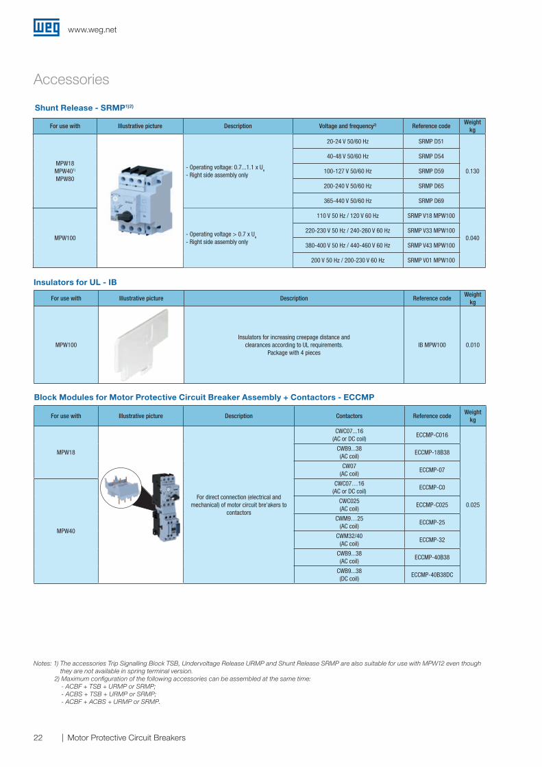
Shunt Release - SRMP1)2)
For use with Illustrative picture Description Voltage and frequency2) Reference codeWeight
kg
MPW18MPW401)
MPW80
- Operating voltage: 0.7...1.1 x Ue
- Right side assembly only
20-24 V 50/60 Hz SRMP D51
0.130
40-48 V 50/60 Hz SRMP D54
100-127 V 50/60 Hz SRMP D59
200-240 V 50/60 Hz SRMP D65
365-440 V 50/60 Hz SRMP D69
MPW100- Operating voltage > 0.7 x Ue
- Right side assembly only
110 V 50 Hz / 120 V 60 Hz SRMP V18 MPW100
0.040220-230 V 50 Hz / 240-260 V 60 Hz SRMP V33 MPW100
380-400 V 50 Hz / 440-460 V 60 Hz SRMP V43 MPW100
200 V 50 Hz / 200-230 V 60 Hz SRMP V01 MPW100
Block Modules for Motor Protective Circuit Breaker Assembly + Contactors - ECCMP
Insulators for UL - IB
For use with Illustrative picture Description Reference codeWeight
kg
MPW100Insulators for increasing creepage distance and
clearances according to UL requirements. Package with 4 pieces
IB MPW100 0.010
For use with Illustrative picture Description Contactors Reference codeWeight
kg
MPW18
For direct connection (electrical and mechanical) of motor circuit bre'akers to
contactors
CWC07...16 (AC or DC coil)
ECCMP-C016
0.025
CWB9...38 (AC coil)
ECCMP-18B38
CW07(AC coil)
ECCMP-07
MPW40
CWC07…16 (AC or DC coil)
ECCMP-C0
CWC025 (AC coil)
ECCMP-C025
CWM9…25 (AC coil)
ECCMP-25
CWM32/40 (AC coil)
ECCMP-32
CWB9...38 (AC coil)
ECCMP-40B38
CWB9...38 (DC coil)
ECCMP-40B38DC
Notes: 1) The accessories Trip Signalling Block TSB, Undervoltage Release URMP and Shunt Release SRMP are also suitable for use with MPW12 even though they are not available in spring terminal version.
2) Maximum configuration of the following accessories can be assembled at the same time: - ACBF + TSB + URMP or SRMP; - ACBS + TSB + URMP or SRMP; - ACBF + ACBS + URMP or SRMP.
www.weg.net
23Motor Protective Circuit Breakers
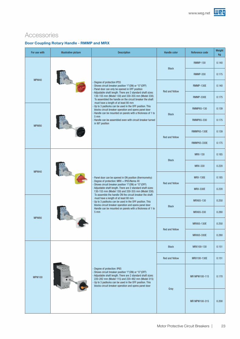
AccessoriesDoor Coupling Rotary Handle - RMMP and MRX
For use with Illustrative picture Description Handle color Reference codeWeight
kg
MPW40- Degree of protection IP55- Shows circuit breaker position “I”(ON) or “O”(OFF)- Panel door can only be opened in OFF position- Adjustable shaft length. There are 2 standard shaft sizes:
130-155 mm (Model 130) and 330-355 mm (Model 330). To assembled the handle on the circuit breaker the shaft
must have a length of at least 80 mm- Up to 3 padlocks can be used in the OFF position. This
blocks circuit breaker operation and opens panel door- Handle can be mounted on panels with a thickness of 1 to
5 mm- Handle can be assembled even with circuit breaker turned
in 90º position
Black
RMMP-130 0.140
RMMP-330 0.175
Red and Yellow
RMMP-130E 0.140
RMMP-330E 0.175
MPW80
Black
RMMP65-130 0.139
RMMP65-330 0.175
Red and Yellow
RMMP65-130E 0.139
RMMP65-330E 0.175
MPW40
- Panel door can be opened in ON position (thermometry)- Degree of protection: MRX = IP65/Nema 4X- Shows circuit breaker position “I”(ON) or “O”(OFF)- Adjustable shaft length. There are 2 standard shaft sizes:
130-155 mm (Model 130) and 330-355 mm (Model 330). To assemble the handle ON the circuit breaker the shaft
must have a length of at least 80 mm- Up to 3 padlocks can be used in the OFF position. This
blocks circuit breaker operation and opens panel door Handle can be mounted on panels with a thickness of 1 to 5 mm
Black
MRX-130 0.185
MRX-330 0.220
Red and Yellow
MRX-130E 0.185
MRX-330E 0.220
MPW80
Black
MRX65-130 0.250
MRX65-330 0.280
Red and Yellow
MRX65-130E 0.250
MRX65-330E 0.280
MPW100
- Degree of protection: IP65- Shows circuit breaker position “I”(ON) or “O”(OFF)- Adjustable shaft length. There are 2 standard shaft sizes:
220-282 mm (Model 115) and 220-482 mm (Model 315)- Up to 3 padlocks can be used in the OFF position. This
blocks circuit breaker operation and opens panel door
Black MRX100-130 0.151
Red and Yellow MRX100-130E 0.151
Gray
MR MPW100-115 0.170
MR MPW100-315 0.200
www.weg.net
24 Motor Protective Circuit Breakers
Accessories
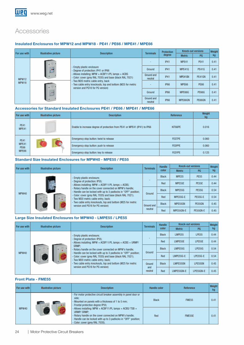
Insulated Enclosures for MPW12 and MPW18 - PE41 / PE66 / MPE41 / MPE66
Large Size Insulated Enclosures for MPW40 - LMPE55 / LPE55
For use with Illustrative picture Description Terminals Protection degree
Knock-out versions WeightkgMetric PG
MPW12MPW18
- Empty plastic enclosure- Degree of protection: IP41 or IP66- Allows installing: MPW + ACBF11/PL lamps + ACBS- Color: cover (grey RAL 7035) and base (black RAL 7021)- Two M20 metric cable entry, back- Two cable entry knockouts, top and bottom (M25 for metric
version and PG16 for PG version)
- IP41 MPE41 PE41 0.41
Ground IP41 MPE41G PE41G 0.41
Ground and neutral
IP41 MPE41GN PE41GN 0.41
- IP66 MPE66 PE66 0.41
Ground IP66 MPE66G PE66G 0.41
Ground and neutral
IP66 MPE66GN PE66GN 0.41
Front Plate - FME55
For use with Illustrative picture Description Handle color ReferenceWeight
kg
MPW40
- For motor protective circuit breaker assembly in panel door or side;
- Mounted on panels with a thickness of 1 to 5 mm;- Frontal protection degree IP55;- Allows installing: MPW + ACBF11/PL lamps + ACBS/ TSB +
URMP/ SRMP;- Rotary handle on the cover connected on MPW's handle;- Handle can be locked with up to 3 padlocks in "OFF" position;- Color: cover (grey RAL 7035).
Black FME55 0.41
Red FME55E 0.41
For use with Illustrative picture Description TerminalsHandle color
Knock-out versions WeightkgMetric PG
MPW40
- Empty plastic enclosure;- Degree of protection: IP55;- Allows installing: MPW + ACBF11/PL lamps + ACBS;- Rotary handle on the cover connected on MPW's handle;- Handle can be locked with up to 3 padlocks in "OFF" position;- Color: cover (grey RAL 7035) and base (black RAL 7021).- Two M20 metric cable entry, back;- Two cable entry knockouts, top and bottom (M25 for metric
version and PG16 for PG version)
-Black MPE55 PE55 0.44
Red MPE55E PE55E 0.44
GroundBlack MPE55G PE55G 0.54
Red MPE55G-E PE55G-E 0.54
Ground and neutral
Black MPE55GN PE55GN 0.45
Red MPE55GN-E PE55GN-E 0.45
Accessories for Standard Insulated Enclosures PE41 / PE66 / MPE41 / MPE66
Standard Size Insulated Enclosures for MPW40 - MPE55 / PE55
For use with Illustrative picture Description TerminalsHandle color
Knock-out versions WeightkgMetric PG
MPW40
- Empty plastic enclosure;- Degree of protection: IP55;- Allows installing: MPW + ACBF11/PL lamps + ACBS + URMP/
SRMP;- Rotary handle on the cover connected on MPW's handle;- Handle can be locked with up to 3 padlocks in "OFF" position;- Color: cover (grey RAL 7035) and base (black RAL 7021).- Two M20 metric cable entry, back;- Two cable entry knockouts, top and bottom (M25 for metric
version and PG16 for PG version)
-Black LMPE55 LPE55 0.44
Red LMPE55E LPE55E 0.44
GroundBlack LMPE55G LPE55G 0.54
Red LMPE55G-E LPE55G-E 0.54
Ground and
neutral
Black LMPE55GN LPE55GN 0.45
Red LMPE55GN-E LPE55GN-E 0.45
For use with Illustrative picture Description ReferenceWeight
kg
PE41 MPE41
Enable to increase degree of protection from PE41 or MPE41 (IP41) to IP66 KIT66PE 0.016
PE41 MPE41 PE66
MPE66
Emergency stop button: twist to release FESTPE 0.060
Emergency stop button: push to release FESPPE 0.060
Emergency stop button: key to release FESYPE 0.125
www.weg.net
25Motor Protective Circuit Breakers
Accessories
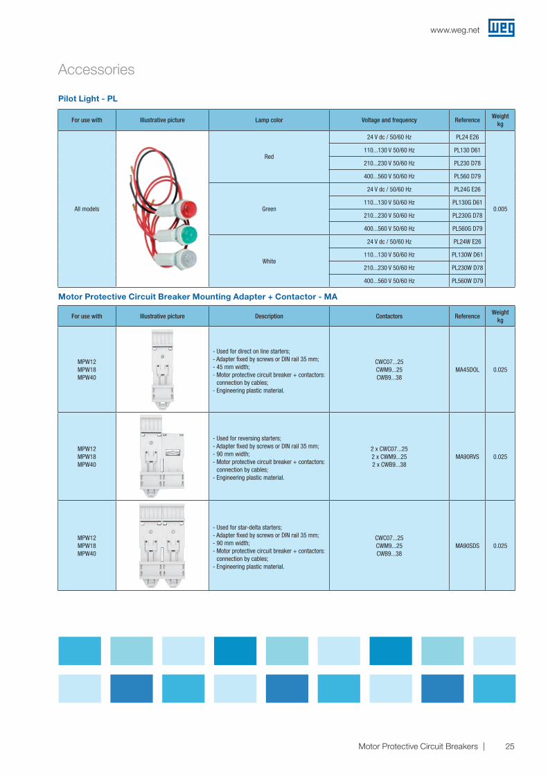
Pilot Light - PL
Motor Protective Circuit Breaker Mounting Adapter + Contactor - MA
For use with Illustrative picture Lamp color Voltage and frequency ReferenceWeight
kg
All models
Red
24 V dc / 50/60 Hz PL24 E26
0.005
110...130 V 50/60 Hz PL130 D61
210...230 V 50/60 Hz PL230 D78
400...560 V 50/60 Hz PL560 D79
Green
24 V dc / 50/60 Hz PL24G E26
110...130 V 50/60 Hz PL130G D61
210...230 V 50/60 Hz PL230G D78
400...560 V 50/60 Hz PL560G D79
White
24 V dc / 50/60 Hz PL24W E26
110...130 V 50/60 Hz PL130W D61
210...230 V 50/60 Hz PL230W D78
400...560 V 50/60 Hz PL560W D79
For use with Illustrative picture Description Contactors ReferenceWeight
kg
MPW12MPW18MPW40
- Used for direct on line starters;- Adapter fixed by screws or DIN rail 35 mm;- 45 mm width;- Motor protective circuit breaker + contactors:
connection by cables;- Engineering plastic material.
CWC07...25CWM9...25CWB9...38
MA45DOL 0.025
MPW12MPW18MPW40
- Used for reversing starters;- Adapter fixed by screws or DIN rail 35 mm;- 90 mm width;- Motor protective circuit breaker + contactors:
connection by cables;- Engineering plastic material.
2 x CWC07...252 x CWM9...252 x CWB9...38
MA90RVS 0.025
MPW12MPW18MPW40
- Used for star-delta starters;- Adapter fixed by screws or DIN rail 35 mm;- 90 mm width;- Motor protective circuit breaker + contactors:
connection by cables;- Engineering plastic material.
CWC07...25CWM9...25CWB9...38
MA90SDS 0.025
www.weg.net
26 Motor Protective Circuit Breakers
Accessories
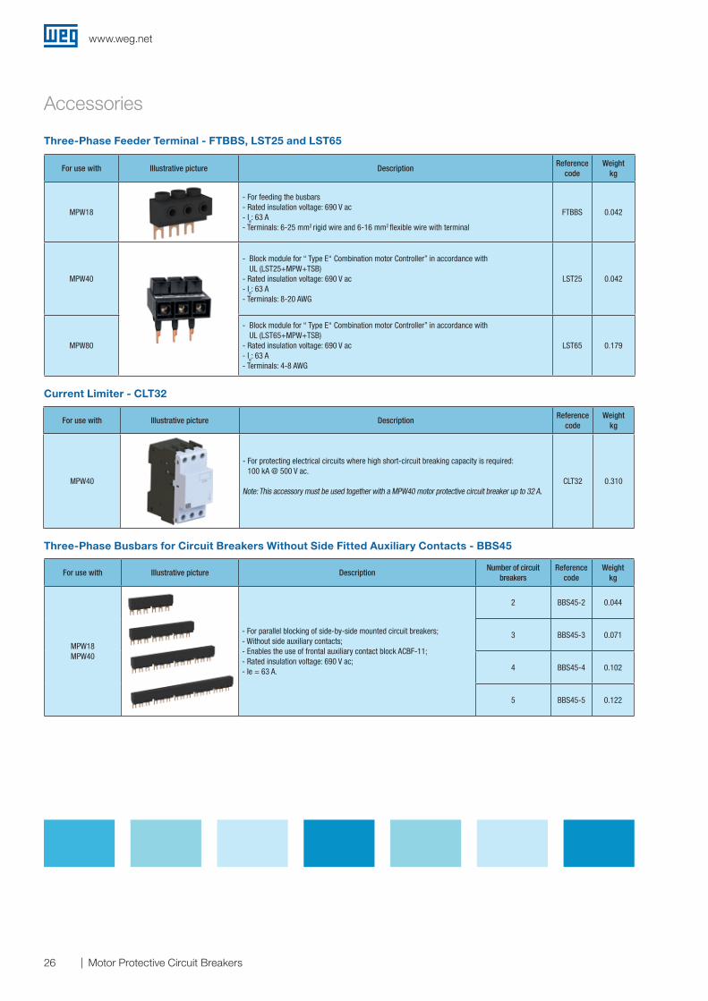
Three-Phase Feeder Terminal - FTBBS, LST25 and LST65
Current Limiter - CLT32
For use with Illustrative picture DescriptionReference
codeWeight
kg
MPW40
- For protecting electrical circuits where high short-circuit breaking capacity is required: 100 kA @ 500 V ac.
Note: This accessory must be used together with a MPW40 motor protective circuit breaker up to 32 A.CLT32 0.310
Three-Phase Busbars for Circuit Breakers Without Side Fitted Auxiliary Contacts - BBS45
For use with Illustrative picture DescriptionNumber of circuit
breakersReference
codeWeight
kg
MPW18MPW40
- For parallel blocking of side-by-side mounted circuit breakers; - Without side auxiliary contacts;- Enables the use of frontal auxiliary contact block ACBF-11;- Rated insulation voltage: 690 V ac;- Ie = 63 A.
2 BBS45-2 0.044
3 BBS45-3 0.071
4 BBS45-4 0.102
5 BBS45-5 0.122
For use with Illustrative picture DescriptionReference
codeWeight
kg
MPW18
- For feeding the busbars- Rated insulation voltage: 690 V ac- Ie: 63 A- Terminals: 6-25 mm2 rigid wire and 6-16 mm2 flexible wire with terminal
FTBBS 0.042
MPW40
- Block module for “ Type E“ Combination motor Controller” in accordance with UL (LST25+MPW+TSB)
- Rated insulation voltage: 690 V ac - Ie: 63 A- Terminals: 8-20 AWG
LST25 0.042
MPW80
- Block module for “ Type E“ Combination motor Controller” in accordance with UL (LST65+MPW+TSB)
- Rated insulation voltage: 690 V ac- Ie: 63 A- Terminals: 4-8 AWG
LST65 0.179
www.weg.net
27Motor Protective Circuit Breakers
Accessories
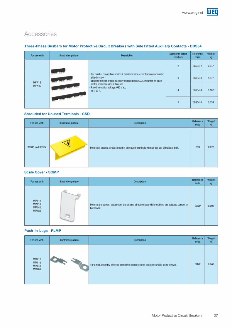
Three-Phase Busbars for Motor Protective Circuit Breakers with Side Fitted Auxiliary Contacts - BBS54
For use with Illustrative picture DescriptionNumber of circuit
breakersReference
codeWeight
kg
MPW18MPW40
- For parallel connection of circuit breakers with screw terminals mounted side-by-side;
- Enables the use of side auxiliary contact block ACBS mounted on each motor protective circuit breaker;
- Rated Insulation Voltage: 690 V ac;- Ie = 63 A.
2 BBS54-2 0.047
3 BBS54-3 0.077
4 BBS54-4 0.102
5 BBS54-5 0.134
Shrouded for Unused Terminals - CSD
Scale Cover - SCMP
Push-In-Lugs - PLMP
For use with Illustrative picture DescriptionReference
codeWeight
kg
BBS45 and BBS54 Protection against direct contact in energized terminals without the use of busbars BBS. CSD 0.020
For use with Illustrative picture DescriptionReference
codeWeight
kg
MPW12MPW18MPW40MPW80
Protects the current adjustment dial against direct contact while enabling the adjusted current to be viewed.
SCMP 0.005
For use with Illustrative picture DescriptionReference
codeWeight
kg
MPW12MPW18MPW40MPW80
For direct assembly of motor protective circuit breaker into any surface using screws. PLMP 0.005
www.weg.net
28 Motor Protective Circuit Breakers
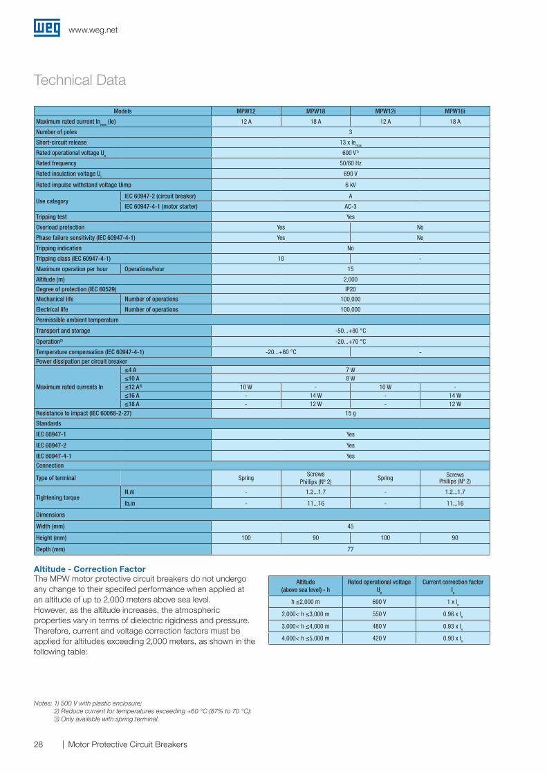
Altitude (above sea level) - h
Rated operational voltage Ue
Current correction factor Iu
h ≤2,000 m 690 V 1 x In
2,000< h ≤3,000 m 550 V 0.96 x In
3,000< h ≤4,000 m 480 V 0.93 x In
4,000< h ≤5,000 m 420 V 0.90 x In
Altitude - Correction FactorThe MPW motor protective circuit breakers do not undergo any change to their specifed performance when applied at an altitude of up to 2,000 meters above sea level.However, as the altitude increases, the atmospheric properties vary in terms of dielectric rigidness and pressure.Therefore, current and voltage correction factors must be applied for altitudes exceeding 2,000 meters, as shown in the following table:
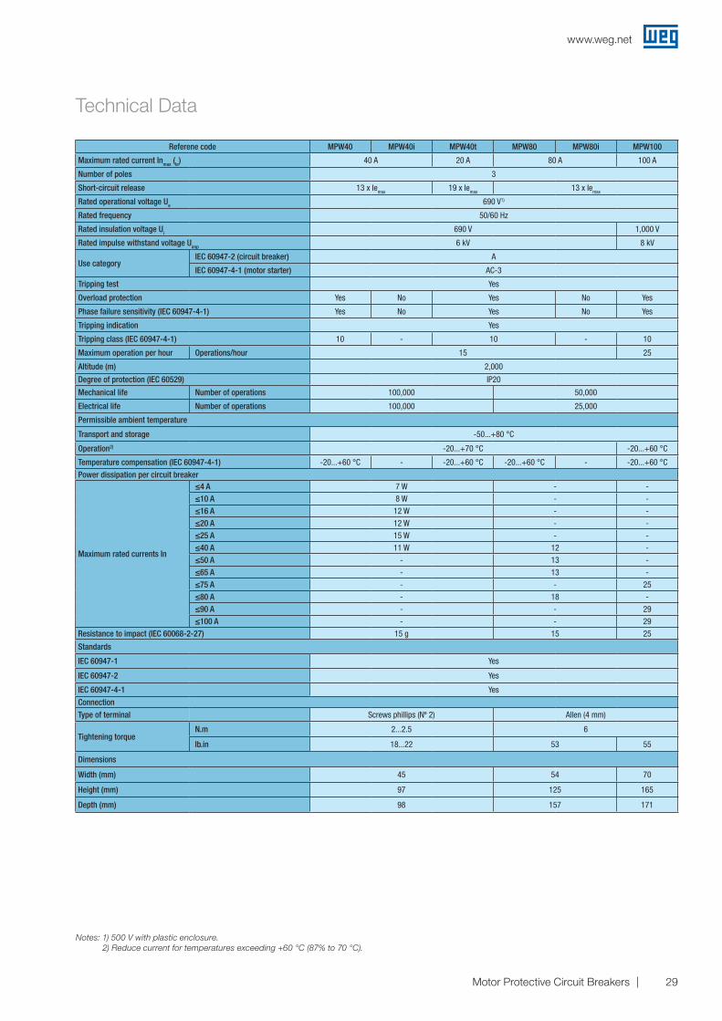
Technical Data
Notes: 1) 500 V with plastic enclosure; 2) Reduce current for temperatures exceeding +60 °C (87% to 70 °C); 3) Only available with spring terminal.
Models MPW12 MPW18 MPW12i MPW18i
Maximum rated current Inmax (Ie) 12 A 18 A 12 A 18 A
Number of poles 3
Short-circuit release 13 x Iemax
Rated operational voltage Ue 690 V1)
Rated frequency 50/60 Hz
Rated insulation voltage Ui 690 V
Rated impulse withstand voltage Uimp 6 kV
Use categoryIEC 60947-2 (circuit breaker) A
IEC 60947-4-1 (motor starter) AC-3
Tripping test Yes
Overload protection Yes No
Phase failure sensitivity (IEC 60947-4-1) Yes No
Tripping indication No
Tripping class (IEC 60947-4-1) 10 -
Maximum operation per hour Operations/hour 15
Altitude (m) 2,000
Degree of protection (IEC 60529) IP20
Mechanical life Number of operations 100,000
Electrical life Number of operations 100,000
Permissible ambient temperature
Transport and storage -50...+80 °C
Operation2) -20...+70 °C
Temperature compensation (IEC 60947-4-1) -20...+60 °C -
Power dissipation per circuit breaker
Maximum rated currents In
≤4 A 7 W≤10 A 8 W≤12 A3) 10 W - 10 W -≤16 A - 14 W - 14 W≤18 A - 12 W - 12 W
Resistance to impact (IEC 60068-2-27) 15 g
Standards
IEC 60947-1 Yes
IEC 60947-2 Yes
IEC 60947-4-1 Yes
Connection
Type of terminal SpringScrews
Phillips (Nº 2)Spring Screws
Phillips (Nº 2)
Tightening torqueN.m - 1.2...1.7 - 1.2...1.7
lb.in - 11...16 - 11...16
Dimensions
Width (mm) 45
Height (mm) 100 90 100 90
Depth (mm) 77
www.weg.net
29Motor Protective Circuit Breakers
Technical Data
Notes: 1) 500 V with plastic enclosure. 2) Reduce current for temperatures exceeding +60 °C (87% to 70 °C).
Referene code MPW40 MPW40i MPW40t MPW80 MPW80i MPW100
Maximum rated current Inmax (Ie) 40 A 20 A 80 A 100 A
Number of poles 3
Short-circuit release 13 x Iemax 19 x Iemax 13 x Iemax
Rated operational voltage Ue 690 V1)
Rated frequency 50/60 Hz
Rated insulation voltage Ui 690 V 1,000 V
Rated impulse withstand voltage Uimp 6 kV 8 kV
Use categoryIEC 60947-2 (circuit breaker) A
IEC 60947-4-1 (motor starter) AC-3
Tripping test Yes
Overload protection Yes No Yes No Yes
Phase failure sensitivity (IEC 60947-4-1) Yes No Yes No Yes
Tripping indication Yes
Tripping class (IEC 60947-4-1) 10 - 10 - 10
Maximum operation per hour Operations/hour 15 25
Altitude (m) 2,000
Degree of protection (IEC 60529) IP20
Mechanical life Number of operations 100,000 50,000
Electrical life Number of operations 100,000 25,000
Permissible ambient temperature
Transport and storage -50...+80 °C
Operation2) -20...+70 °C -20...+60 °C
Temperature compensation (IEC 60947-4-1) -20...+60 °C - -20...+60 °C -20...+60 °C - -20...+60 °C
Power dissipation per circuit breaker
Maximum rated currents In
≤4 A 7 W - -≤10 A 8 W - -≤16 A 12 W - -≤20 A 12 W - -≤25 A 15 W - -≤40 A 11 W 12 -
≤50 A - 13 -
≤65 A - 13 -≤75 A - - 25≤80 A - 18 -≤90 A - - 29≤100 A - - 29
Resistance to impact (IEC 60068-2-27) 15 g 15 25
Standards
IEC 60947-1 Yes
IEC 60947-2 Yes
IEC 60947-4-1 Yes
Connection
Type of terminal Screws phillips (Nº 2) Allen (4 mm)
Tightening torqueN.m 2...2.5 6
lb.in 18...22 53 55
Dimensions
Width (mm) 45 54 70
Height (mm) 97 125 165
Depth (mm) 98 157 171
www.weg.net
30 Motor Protective Circuit Breakers
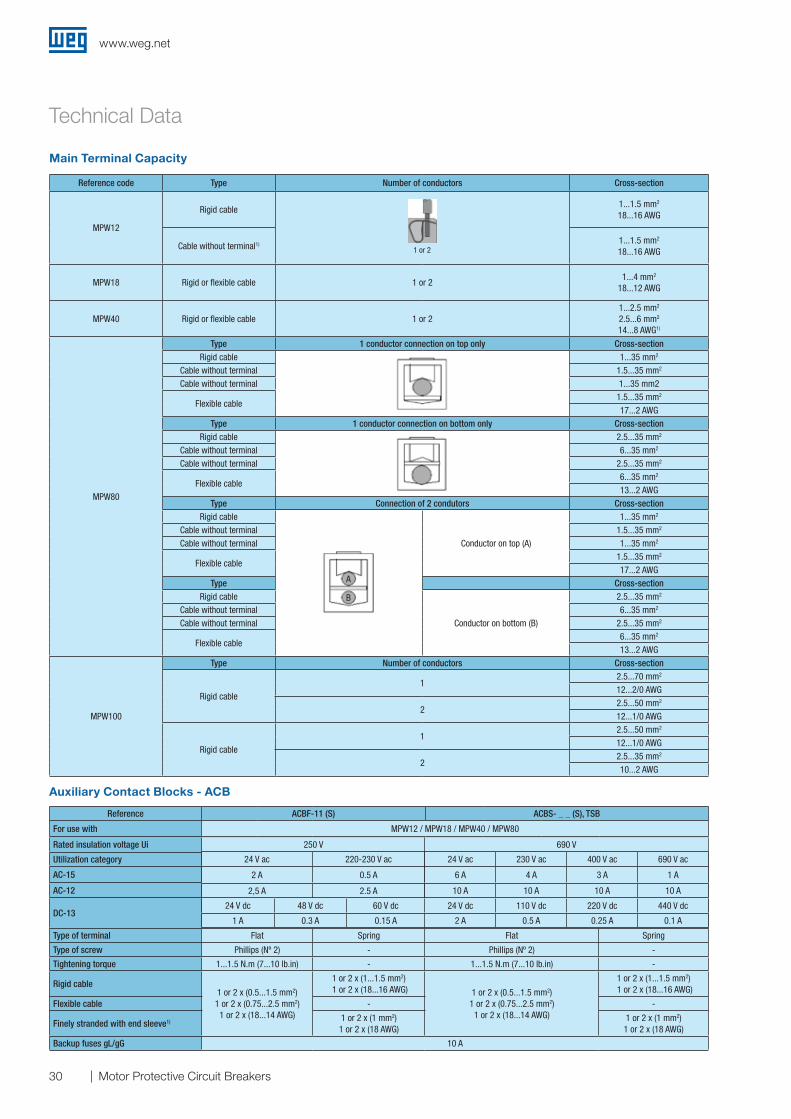
Main Terminal Capacity
Technical Data
Auxiliary Contact Blocks - ACB
Reference ACBF-11 (S) ACBS- _ _ (S), TSB
For use with MPW12 / MPW18 / MPW40 / MPW80
Rated insulation voltage Ui 250 V 690 V
Utilization category 24 V ac 220-230 V ac 24 V ac 230 V ac 400 V ac 690 V ac
AC-15 2 A 0,5 A 6 A 6 A 3 A 1 A
AC-12 2.5 A 2,5 A 10 A 10 A 10 A 10 A
DC-1324 V dc 48 V dc 60 V dc 24 V dc 110 V dc 220 V dc 440 V dc
1 A 0,3 A 0,15 A 2 A 0,5 A 0,25 A 0,1 A
24 V ac 220-230 V ac
2 A 0.5 A
2,5 A 2.5 A
Type of terminal Flat Spring Flat Spring
Type of screw Phillips (Nº 2) - Phillips (Nº 2) -
Tightening torque 1...1.5 N.m (7...10 lb.in) - 1...1.5 N.m (7...10 lb.in) -
Rigid cable1 or 2 x (0.5...1.5 mm2)1 or 2 x (0.75...2.5 mm2)
1 or 2 x (18...14 AWG)
1 or 2 x (1...1.5 mm2) 1 or 2 x (18...16 AWG) 1 or 2 x (0.5...1.5 mm2)
1 or 2 x (0.75...2.5 mm2) 1 or 2 x (18...14 AWG)
1 or 2 x (1...1.5 mm2) 1 or 2 x (18...16 AWG)
Flexible cable - -
Finely stranded with end sleeve1) 1 or 2 x (1 mm2) 1 or 2 x (18 AWG)
1 or 2 x (1 mm2) 1 or 2 x (18 AWG)
Backup fuses gL/gG 10 A
24 V dc 48 V dc 60 V dc
1 A 0.3 A 0.15 A
24 V ac 230 V ac 400 V ac 690 V ac
6 A 4 A 3 A 1 A
10 A 10 A 10 A 10 A
24 V dc 110 V dc 220 V dc 440 V dc
2 A 0.5 A 0.25 A 0.1 A
Reference code Type Number of conductors Cross-section
MPW12
Rigid cable
1 or 2
1...1.5 mm2
18...16 AWG
Cable without terminal1) 1...1.5 mm2
18...16 AWG
MPW18 Rigid or flexible cable 1 or 21...4 mm2
18...12 AWG
MPW40 Rigid or flexible cable 1 or 21...2.5 mm2
2.5...6 mm2
14...8 AWG1)
MPW80
Type 1 conductor connection on top only Cross-sectionRigid cable 1...35 mm2
Cable without terminal 1.5...35 mm2
Cable without terminal 1...35 mm2
Flexible cable1.5...35 mm2
17...2 AWGType 1 conductor connection on bottom only Cross-section
Rigid cable 2.5...35 mm2
Cable without terminal 6...35 mm2
Cable without terminal 2.5...35 mm2
Flexible cable6...35 mm2
13...2 AWGType Connection of 2 condutors Cross-section
Rigid cable
A
B
Conductor on top (A)
1...35 mm2
Cable without terminal 1.5...35 mm2
Cable without terminal 1...35 mm2
Flexible cable1.5...35 mm2
17...2 AWGType Cross-section
Rigid cable
Conductor on bottom (B)
2.5...35 mm2
Cable without terminal 6...35 mm2
Cable without terminal 2.5...35 mm2
Flexible cable6...35 mm2
13...2 AWG
MPW100
Type Number of conductors Cross-section
Rigid cable1
2.5...70 mm2
12...2/0 AWG
22.5...50 mm2
12...1/0 AWG
Rigid cable1
2.5...50 mm2
12...1/0 AWG
22.5...35 mm2
10...2 AWG
www.weg.net
31Motor Protective Circuit Breakers
Technical Data
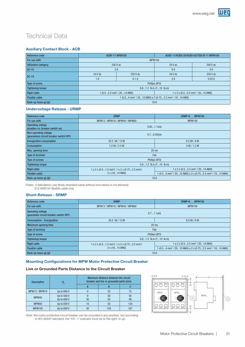
Shunt Release - SRMP
Reference code SRMP SRMP-K_ _ MPW100
For use with MPW12 / MPW18 / MPW40 / MPW80 MPW100
Operating voltage (guarantee circuit breaker switch OFF)
0.7...1.1xUs
Consumption - Energization 20.2 VA / 13 W 8.5 VA / 6 W
Maximum opening time 20 ms
Type of terminal Flat
Type of screw Phillips (Nº2)
Tightening torque 0.8...1.2 N.m (7...10 lb.in)
Rigid cable 1 o 2 x (0.5...1.5 mm2). 1 o 2 x (0.75...2.5 mm2).2 x (18...14 AWG)
1 o 2 x (0.5...2.5 mm2 / 20...14 AWG)
Flexible cable 1 (0.5...4 mm2 / 20...10 AWG) o 2 x (0.75...2.5 mm2 / 18...14 AWG)
Back-up fuses gL/gG 10 A
Notes: 1) Mandatory use (finely stranded cable without end sleeve is not allowed).2) 8 AWG for flexible cable only.
Undervoltage Release - URMP
Reference code ACBF-11 MPW100 ACBS-11/ACBS-20/ACBS-02/TSB AT-11 MPW100
For use with MPW100
Utilization category 240 V ac 24 V ac 240 V ac
AC-15 3 A 6 A 4 A
DC-1324 V dc 220 V dc 24 V dc 220 V dc
1 A 0.1 A 2 A 0.25 A
Type of screw Phillips (Nº2)
Tightening torque 0.8...1.2 N.m (7...10 lb.in)
Rigid cable 1 (0.5...2.5 mm2 / 20...14 AWG) 1 o 2 x (0.5...2.5 mm2 / 20...14 AWG)
Flexible cable 1 (0.5...4 mm2 / 20...10 AWG) o 2 (0.75...2.5 mm2 / 18...14 AWG)
Back-up fuses gL/gG 16 A
Auxiliary Contact Block - ACB
Reference code URMP URMP-K_ _ MPW100
For use with MPW12 / MPW18 / MPW40 / MPW80 MPW100Operating voltage (enables cir. breaker switch on)
0.85...1.1xUs
Non-operating voltage (guarantees circuit breaker switch OFF)
0.7...0.35xUs
Energization consumption 20.2 VA / 13 W 8.5 VA / 6 W
Consumption 7.2 VA / 2.4 W 3 VA / 1.2 W
Max. opening time 20 ms
Type of terminal Flat
Type of screws Phillips (Nº2)
Tightening torque 0.8...1.2 N.m (7...10 lb.in)
Rigid cable 1 o 2 x (0.5...1.5 mm2). 1 o 2 x (0.75...2.5 mm2).2 x (18...14 AWG)
1 o 2 x (0.5...2.5 mm2 / 20...14 AWG)
Flexible cable 1 (0.5...4 mm2 / 20...10 AWG) o 2 x (0.75...2.5 mm2 / 18...14 AWG)
Back-up fuses gL/gG 10 A
Live or Grounded Parts Distance to the Circuit Breaker
Description Ue
Minimum distance between the circuit breaker and live or grounded parts (mm)
A B C
MPW12 / MPW18 Up to 690 V 9 20 75
MPW40Up to 500 VUp to 690 V
930
3050
9595
MPW80 Up to 690 V 10 50 150
MPW100 Up to 690 V 30 150 167
Note: the motor protective circuit breaker can be mounted in any position, but according to IEC 60447 standard, the “On - I” indicator must be to the right, or up.
Mounting Configurations for MPW Motor Protective Circuit Breaker
A
1L1
2T1 2T14T2 4T2
1L13L2
MPW...
3L2
MPW...MPW...
5L3
6T3 6T3
5L3
A C
BB
www.weg.net
32 Motor Protective Circuit Breakers
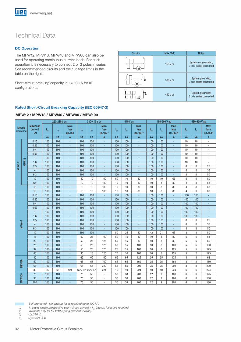
Models reference
Maximum current
(A)
220-230 V ac 380-415 V ac 440 V ac 460-500 V ac 630-690 V ac
Icu Ics
Max. fuse
(gL/gG)Icu Ics
Max. fuse
(gL/gG)1)
Icu Ics
Max. fuse
(gL/gG)1)
Icu Ics
Max. fuse
(gL/gG)1)
Icu Ics
Max. fuse
(gL/gG)1)
kA kA A kA kA A kA kA A kA kA A kA kA A
MPW
18 MPW
12
0.16 100 100 - 100 100 - 100 100 - 100 100 - 10 10 -
0.25 100 100 - 100 100 - 100 100 - 100 100 - 10 10 -
0.4 100 100 - 100 100 - 100 100 - 100 100 - 10 10 -
0.63 100 100 - 100 100 - 100 100 - 100 100 - 10 10 -
1 100 100 - 100 100 - 100 100 - 100 100 - 10 10 -
1.6 100 100 - 100 100 - 100 100 - 100 100 - 10 10 -
2.5 100 100 - 100 100 - 100 100 - 100 100 - 8 8 25
4 100 100 - 100 100 - 100 100 - 100 100 - 8 8 35
6.3 100 100 - 100 100 - 100 100 - 100 100 - 8 8 50
10 100 100 - 50 10 100 50 10 80 10 10 63 5 5 50
122) 100 100 - 10 10 100 10 10 80 10 8 80 4 3 63
16 100 100 - 10 10 100 10 10 80 10 8 80 4 3 63
18 100 100 - 10 10 100 10 10 80 10 8 80 4 3 80
MPW
40
0.16 100 100 - 100 100 - 100 100 - 100 100 - 100 100 -
0.25 100 100 - 100 100 - 100 100 - 100 100 - 100 100 -
0.4 100 100 - 100 100 - 100 100 - 100 100 - 100 100 -
0.63 100 100 - 100 100 - 100 100 - 100 100 - 100 100 -
1 100 100 - 100 100 - 100 100 - 100 100 - 100 100 -
1.6 100 100 - 100 100 - 100 100 - 100 100 - 100 100 -
2.5 100 100 - 100 100 - 100 100 - 100 100 - 8 8 25
4 100 100 - 100 100 - 100 100 - 100 100 - 8 8 35
6.3 100 100 - 100 100 - 100 100 - 100 100 - 8 8 50
10 100 100 - 100 100 - 50 25 80 42 21 63 8 8 50
16 100 100 - 50 25 100 50 15 80 10 8 80 5 5 63
20 100 100 - 50 25 125 50 15 80 10 8 80 5 5 80
25 100 100 - 50 25 125 50 15 100 10 8 100 5 5 100
32 100 100 - 50 25 125 25 15 100 10 8 125 5 5 125
40 100 100 - 30 15 125 20 10 100 10 5 125 5 2 125
MPW
80
40 100 100 - 65 65 160 65 65 125 35 35 125 8 8 63
50 100 100 - 65 65 160 65 65 160 35 35 160 8 8 160
65 100 100 - 65 65 200 65 65 200 35 35 200 8 8 200
80 65 65 124 653) / 254) 253) / 104) 224 10 10 224 10 10 224 6 6 224
MPW
100 75 100 100 - 75 50 - 50 38 200 12 9 160 6 6 125
90 100 100 - 75 50 - 50 38 200 12 9 160 6 6 160
100 100 100 - 75 50 - 50 38 200 12 9 160 6 6 160
The MPW12, MPW18, MPW40 and MPW80 can also be used for operating continuous current loads. For such operation it is necessary to connect 2 or 3 poles in series.See recommended circuits and their voltage limits in the table on the right.
Short-circuit breaking capacity Icu = 10 kA for all configurations.
Circuits Máx. V dc NotesL+ L-
150 V dcSystem not grounded;
2 pole series connected
L+ L-
300 V dcSystem grounded;
2 pole series connected
L+ L-
450 V dcSystem grounded;
3 pole series connected
Rated Short-Circuit Breaking Capacity (IEC 60947-2)
MPW12 / MPW18 / MPW40 / MPW80 / MPW100
Self-protected - No backup fuses required up to 100 kA. 1) In cases where prospective short-circuit current > Icu ,backup fuses are required. 2) Available only for MPW12 (spring terminal version). 3) Ue≤380 V. 4) Ue=400/415 V.
DC Operation
Technical Data
www.weg.net
33Motor Protective Circuit Breakers
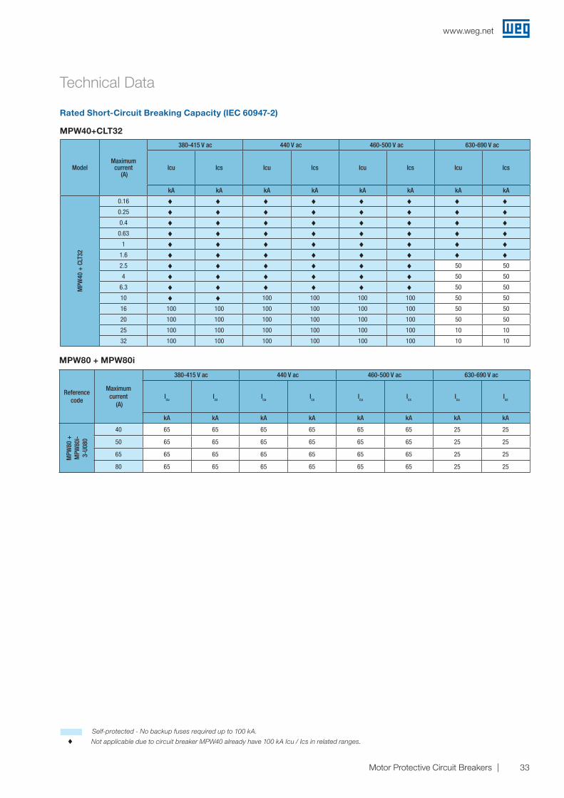
Rated Short-Circuit Breaking Capacity (IEC 60947-2)
MPW40+CLT32
ModelMaximum
current (A)
380-415 V ac 440 V ac 460-500 V ac 630-690 V ac
Icu Ics Icu Ics Icu Ics Icu Ics
kA kA kA kA kA kA kA kA
MPW
40 +
CLT
32
0.16 ♦ ♦ ♦ ♦ ♦ ♦ ♦ ♦0.25 ♦ ♦ ♦ ♦ ♦ ♦ ♦ ♦0.4 ♦ ♦ ♦ ♦ ♦ ♦ ♦ ♦
0.63 ♦ ♦ ♦ ♦ ♦ ♦ ♦ ♦1 ♦ ♦ ♦ ♦ ♦ ♦ ♦ ♦
1.6 ♦ ♦ ♦ ♦ ♦ ♦ ♦ ♦2.5 ♦ ♦ ♦ ♦ ♦ ♦ 50 50
4 ♦ ♦ ♦ ♦ ♦ ♦ 50 50
6.3 ♦ ♦ ♦ ♦ ♦ ♦ 50 50
10 ♦ ♦ 100 100 100 100 50 50
16 100 100 100 100 100 100 50 50
20 100 100 100 100 100 100 50 50
25 100 100 100 100 100 100 10 10
32 100 100 100 100 100 100 10 10
MPW80 + MPW80i
Reference code
Maximumcurrent
(A)
380-415 V ac 440 V ac 460-500 V ac 630-690 V ac
Icu Ics Icu Ics Icu Ics Icu Ics
kA kA kA kA kA kA kA kA
MPW
80 +
M
PW80
i-3-
U080
40 65 65 65 65 65 65 25 25
50 65 65 65 65 65 65 25 25
65 65 65 65 65 65 65 25 25
80 65 65 65 65 65 65 25 25
Self-protected - No backup fuses required up to 100 kA.
♦ Not applicable due to circuit breaker MPW40 already have 100 kA Icu / Ics in related ranges.
Technical Data
www.weg.net
34 Motor Protective Circuit Breakers
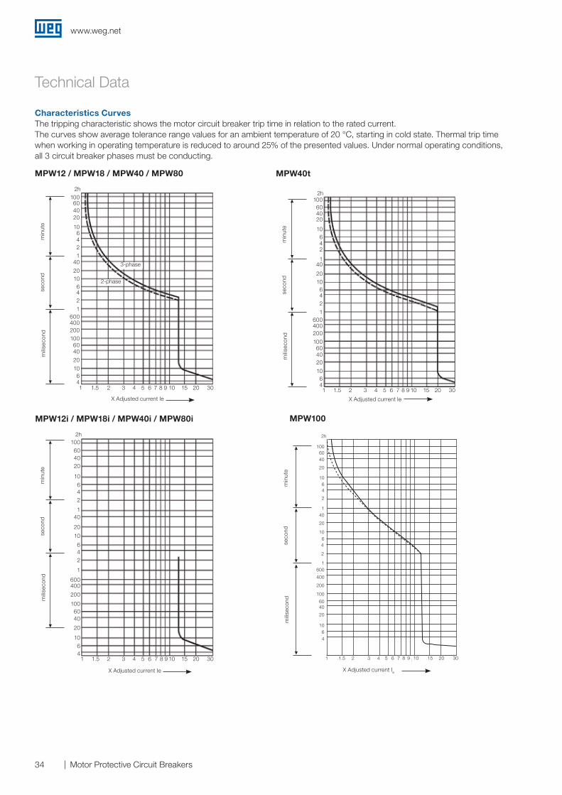
Characteristics CurvesThe tripping characteristic shows the motor circuit breaker trip time in relation to the rated current.The curves show average tolerance range values for an ambient temperature of 20 °C, starting in cold state. Thermal trip time when working in operating temperature is reduced to around 25% of the presented values. Under normal operating conditions, all 3 circuit breaker phases must be conducting.
MPW12 / MPW18 / MPW40 / MPW80
MPW12i / MPW18i / MPW40i / MPW80i
MPW40t
X Adjusted current Ie
seco
ndm
inut
e
3-phase
2-phase
mili
seco
nd
2h100604020
106421
40
20106421
6004002001006040
20
10641 1.5 2 3 4 5 6 7 8 9 10 15 20 30
seco
ndm
inut
em
ilise
cond
2h100604020
10642
140
2010642
1600400200
100604020
10641 1.5 2 3 4 5 6 7 8 9 10 15 20 30
X Adjusted current Ie
seco
ndm
inut
em
ilise
cond
2h100604020
10
642
140
20
10
642
1
600400
200
1006040
20
10
64
1 1.5 2 3 4 5 6 7 8 9 10 15 20 30
X Adjusted current Ie
MPW100
segu
ndo
min
uto
mili
segu
ndo
X Corrente ajustada Ie
100
2h
6040
20
1064
2
140
20
10642
1600400
200100604020
1064
1 1,5 3 8 910 15
2h
1006040
20
1064
2
140
20
1064
2
1600
400
200
100
6040
20
1064
1 1.5 2 3 4 5 6 7 8 9 10 15 20 30
X Corrente ajustada IeX Adjusted current Ie
seco
ndm
inut
em
ilise
cond
Technical Data
www.weg.net
35Motor Protective Circuit Breakers
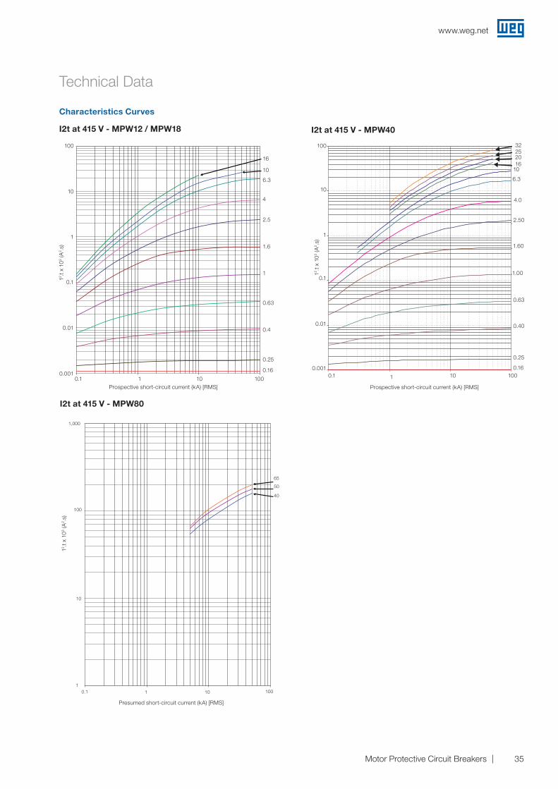
I2t at 415 V - MPW40I2t at 415 V - MPW12 / MPW18
Prospective short-circuit current (kA) [RMS]
12 .t x
103
(A2 .
s)
0,001
0,01
0,1
1
10
100
0,1 1 10 100
()
100
10
1
0.1
16
10
6.3
4
2.5
1.6
1
0.63
0.4
0.25
0.16
0.1 1 10 100
0.01
0.001
12 .t x
103
(A2 .
s)
Prospective short-circuit current (kA) [RMS]
100
10
1
0.1
32252016
10
6.3
4.0
2.50
1.60
1.00
0.63
0.40
0.25
0.160.1 1 10 100
0.01
0.001
I2t at 415 V - MPW80
1
10
100
1000
0,1 1 10 100
65
50
40
Corrente de curto-circuito presumida (kA) [RMS]
12 .t x
103
(A2 .
s)
1,000
65
50
40
100
10
10.1 1 10 100
Presumed short-circuit current (kA) [RMS]
12 .t x
103
(A2 .
s)
Characteristics Curves
Technical Data
www.weg.net
36 Motor Protective Circuit Breakers
Technical Data
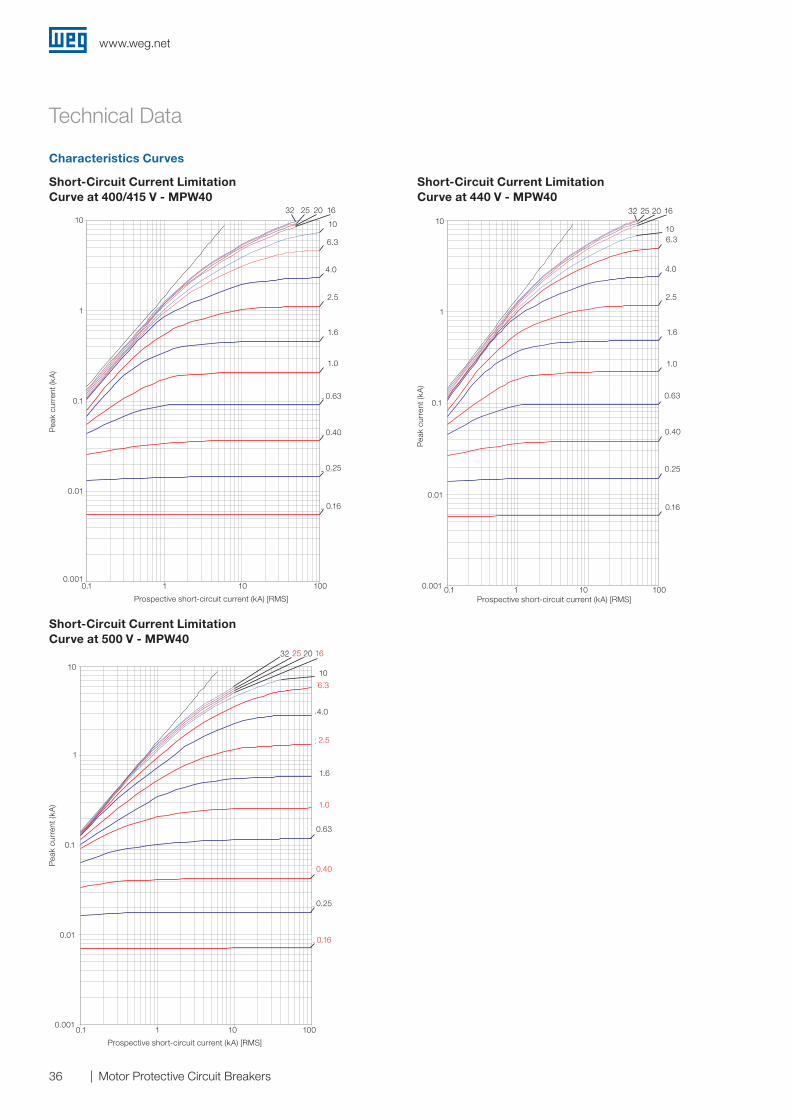
Characteristics Curves
Short-Circuit Current Limitation Curve at 440 V - MPW40
Short-Circuit Current Limitation Curve at 500 V - MPW40
Short-Circuit Current Limitation Curve at 400/415 V - MPW40
Prospective short-circuit current (kA) [RMS]
Pea
k cu
rren
t (kA
)
32 20
10
4.0
1.6
0.63
0.40
1.0
2.5
6.3
1625
0.16
0.25
1001010.10.001
0.01
0.1
1
10
Pea
k cu
rren
t (kA
)
Prospective short-circuit current (kA) [RMS]
32 20
10
4.0
1.6
0.63
0.40
1.0
2.5
6.3
1625
0.16
0.25
1001010.10.001
0.01
0.1
1
10
Pea
k cu
rren
t (kA
)
Prospective short-circuit current (kA) [RMS]
32 20
10
4.0
1.6
0.63
0.40
1.0
2.5
6.3
1625
0.16
0.25
1001010.10.001
0.01
0.1
1
10
www.weg.net
37Motor Protective Circuit Breakers
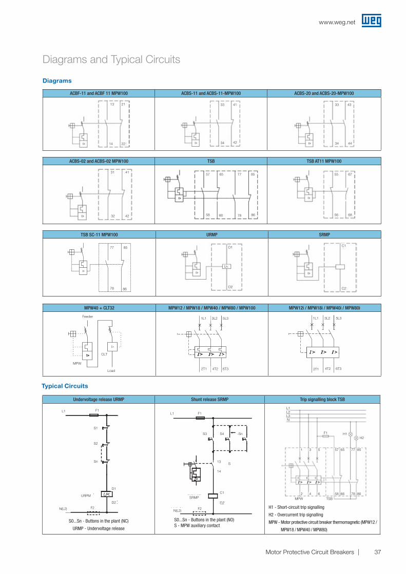
Diagrams and Typical Circuits
Diagrams
Typical Circuits
Undervoltage release URMP Shunt release SRMP Trip signalling block TSB
L1 F1
F2N(L2)
URPM
S1
D1
D2
S2
Sn
S0...Sn - Buttons in the plant (NC)
URMP - Undervoltage release
S
C1
14
13
L1
N(L2)
SRMP
F1
F2
S3 S4 -Sn
C2
S0...Sn - Buttons in the plant (NO)S - MPW auxiliary contact
MPW TSB
L1L2L3N
F1 H1H2
85776557531
2 4 6 58 66 78 86
L1
1
2MPW TSB
3
4
5
6
57
58
77
78
65
66
85
86
F1 H1H2
L2L3N
H1 - Short-circuit trip signalling
H2 - Overcurrent trip signalling
MPW - Motor protective circuit breaker thermomagnetic (MPW12 /
MPW18 / MPW40 / MPW80)
MPW40 + CLT32 MPW12 / MPW18 / MPW40 / MPW80 / MPW100 MPW12i / MPW18i / MPW40i / MPW80i
ALIMENTADOR
MPW25
CARGA
CLT25
Feeder
MPW
CLT
Load
1L1
2T1
3L2
4T2
5L3
6T3
1L1
2T1
3L2
4T2
5L3
6T3
ACBF-11 and ACBF 11 MPW100 ACBS-11 and ACBS-11-MPW100 ACBS-20 and ACBS-20-MPW100
13 21
2214
33 41
4234 34
33 43
44
ACBS-02 and ACBS-02 MPW100 TSB TSB AT11 MPW100
4131
32 42
6557
58 66 78 86
8577 6755
56 68
TSB SC-11 MPW100 URMP SRMP
78
77
86
85
I>
8577
78 86
D1
U<
D2
C1
C2
33 41
42 34
33 43
44
66
34
www.weg.net
38 Motor Protective Circuit Breakers
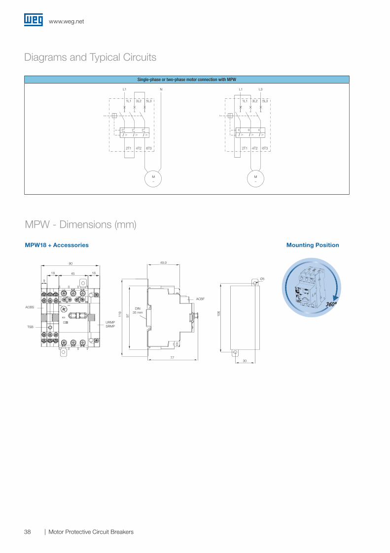
MPW - Dimensions (mm)
MPW18 + Accessories Mounting Position
49,990 49.9
30
Ø5
77
45
119
106
97
1818
9
ACBS
ACBF
TSBURMP SRMP
DIN35 mm
Diagrams and Typical Circuits
Single-phase or two-phase motor connection with MPW
I > I > I >
2T1 4T2 6T3
1L1 3L2 5L3
I > I > I >
2T1 4T2 6T3
1L1 3L2 5L3
M~
M~
L1 N L1 L3L1 L1 L3
1L1 1L1
2T1 2T1
3L2 3L2
4T2 4T2
5L3 5L3
6T3 6T3
N
M M~ ~
www.weg.net
39Motor Protective Circuit Breakers
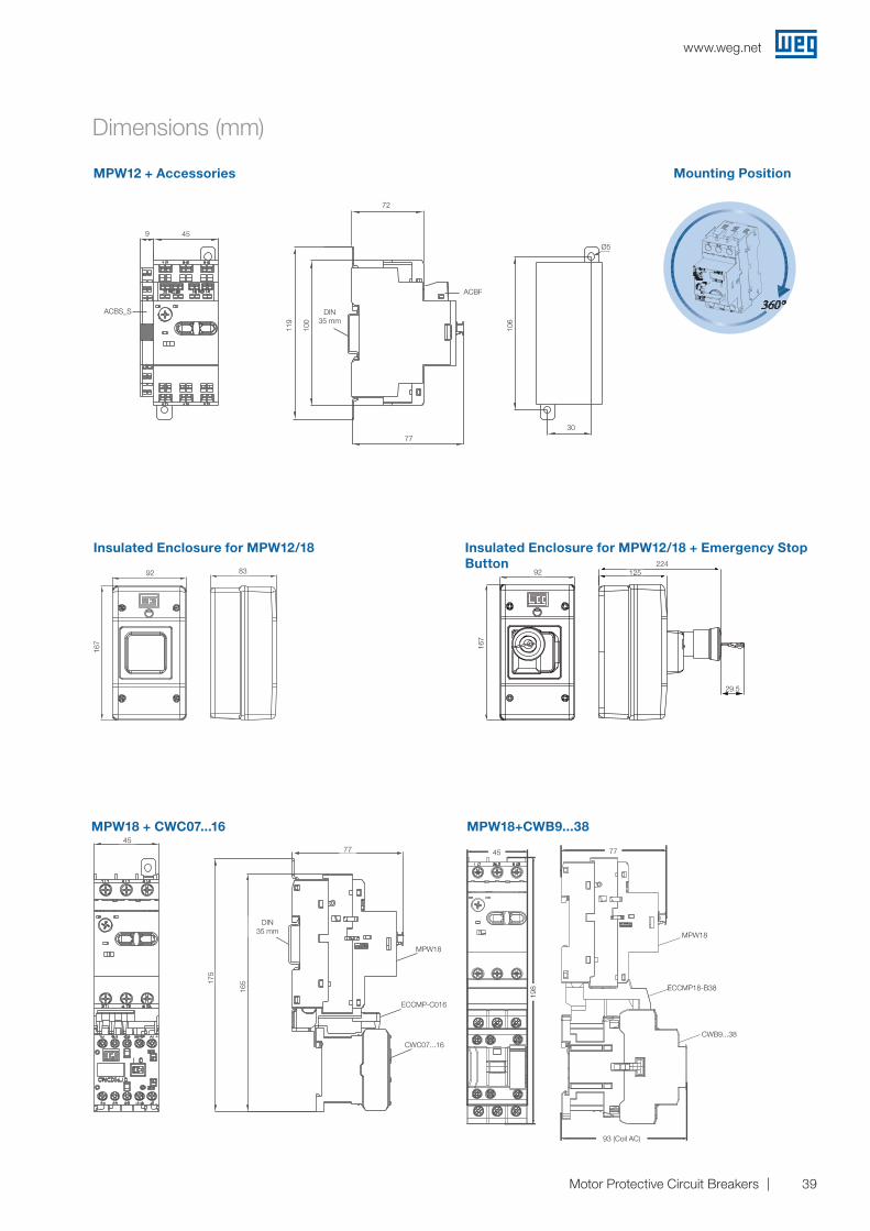
Dimensions (mm)
MPW12 + Accessories
Insulated Enclosure for MPW12/18
MPW18 + CWC07...16 MPW18+CWB9...38
Insulated Enclosure for MPW12/18 + Emergency Stop Button
ACBS_S
72
Mounting Position
45
MPW18
ECCMP18-B38
CWB9...38
4577
DIN35 mm
MPW18
ECCMP-C016
CWC07...16
175
165
77
93 (BOBINA CA)
45
198
45
93 (Coil AC)
77
198
92
167
125224
92 92224
125
29.5
83
167
167
72
Ø5
119
100
106
77
30
DIN35 mm
ACBF
ACBS_S
9
www.weg.net
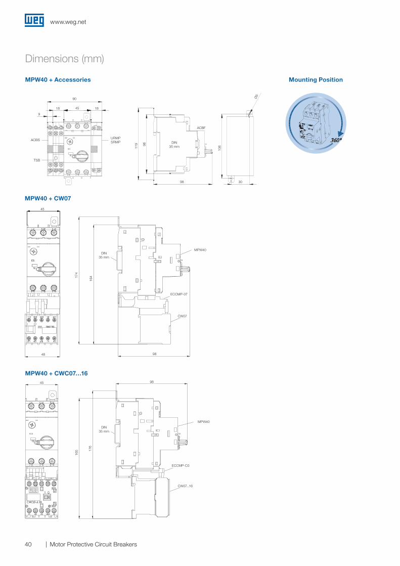
40 Motor Protective Circuit Breakers
Dimensions (mm)
MPW40 + CW07
MPW40 + CWC07…16
MPW40 + Accessories Mounting Position
URMPSRMP
ACBS
TSB
ACBF
90
1818 45
45
45
48 98
98
MPW40
MPW40
ECCMP-07
ECCMP-C0
CW07
CW07...16
DIN35 mm
DIN35 mm
164
176
174
165
98 30
Ø5
DIN35 mm11
9
10698
9
www.weg.net
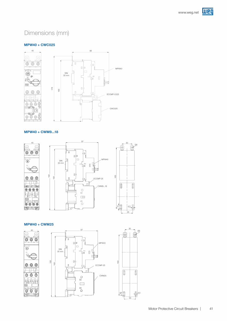
41Motor Protective Circuit Breakers
Dimensions (mm)
MPW40 + CWC025
MPW40 + CWM9...18
MPW40 + CWM25
45
45
45
176
193
193
165
183
183
183
183
98
97
97
30
30
4.5
4.5
35
35
1010
Ø5
Ø5
DIN35 mm
DIN35 mm
DIN35 mm
MPW40
MPW40
MPW40
ECCMP-C025
ECCMP-25
ECCMP-25
CWC025
CWM9...18
CWM25
www.weg.net
42 Motor Protective Circuit Breakers
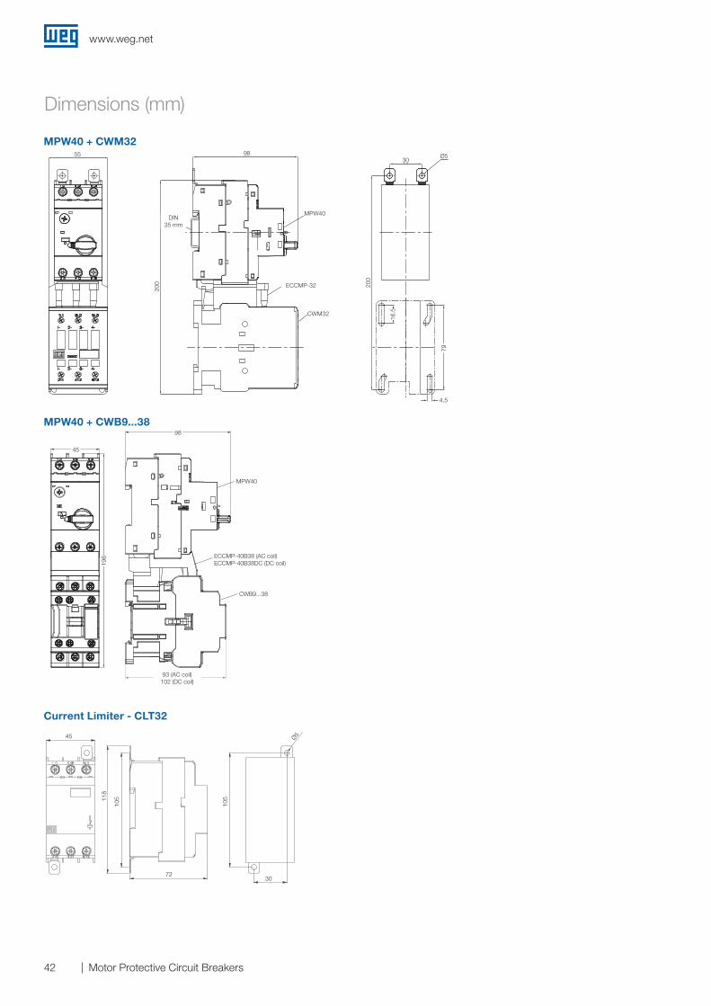
Dimensions (mm)
MPW40 + CWM32
MPW40 + CWB9...38
Current Limiter - CLT32
200
Ø530
200
9855
ECCMP-32
CWM32/40
Trilho DIN35 mm
16,5
4,5
79
98
45
98
45
102 (BOBINA CC)93 (BOBINA CA)
198
5520
0 200
9830
4.516
.5
79
98
45
45
7230
Ø5
118
105
105
198
93 (AC coil) 102 (DC coil)
Ø5
DIN35 mm
MPW40
ECCMP-32
CWM32
MPW40
CWB9...38
ECCMP-40B38 (AC coil)ECCMP-40B38DC (DC coil)

www.weg.net
43Motor Protective Circuit Breakers
Dimensions (mm)
Front Plate - FME55
Insulated Enclosure - MPE55/PE55 (IP55)
Insulated Enclosure - MLPE55/LPE55 (IP55)
105
85
167
15515
5
Ø4.
5
109 109
129
167
157
155
Ø4.
592
129
109
92
89
87
1738
63
40
60
3.8
30
A ≤8
Drilling
www.weg.net
44 Motor Protective Circuit Breakers
Dimensions (mm)
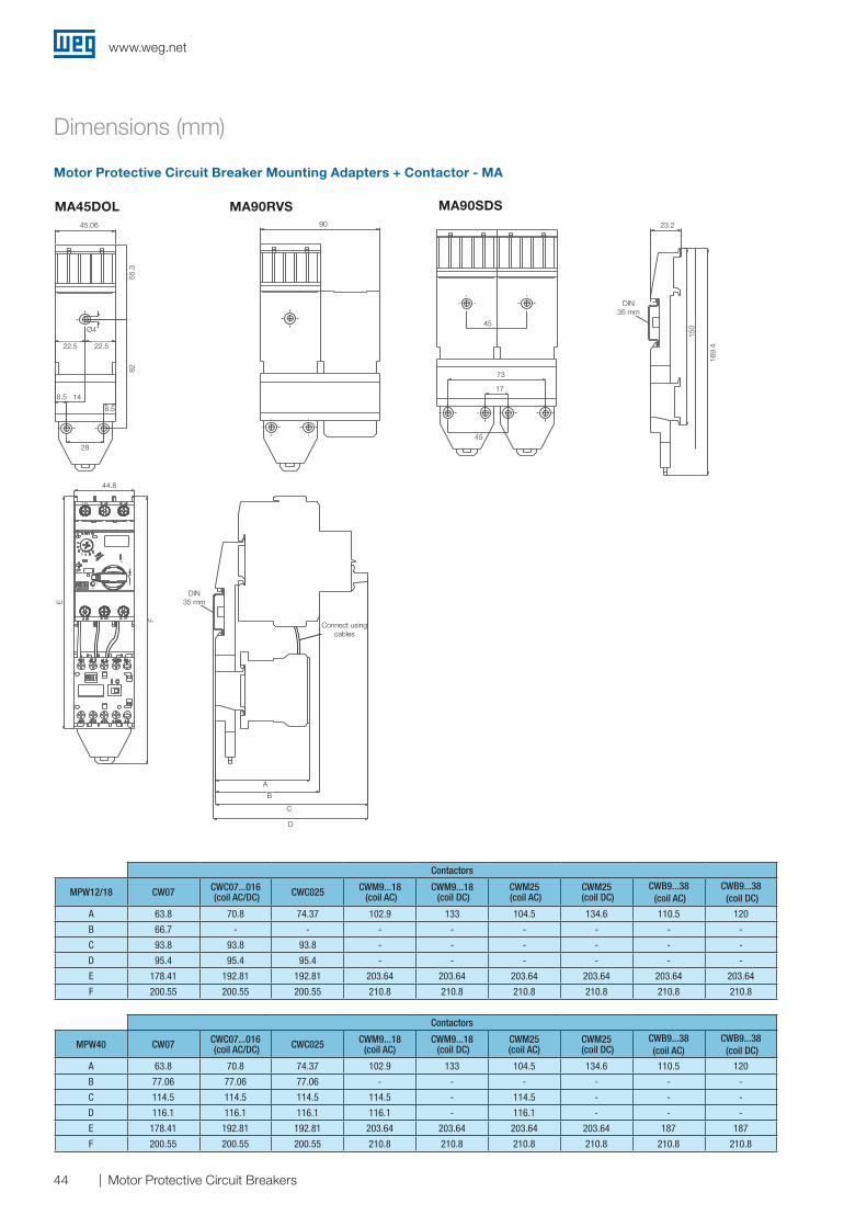
Motor Protective Circuit Breaker Mounting Adapters + Contactor - MA
Contactors
MPW12/18 CW07 CWC07...016 (coil AC/DC) CWC025 CWM9...18
(coil AC)CWM9...18 (coil DC)
CWM25 (coil AC)
CWM25 (coil DC)
CWB9...38 (coil AC)
CWB9...38 (coil DC)
A 63.8 70.8 74.37 102.9 133 104.5 134.6 110.5 120
B 66.7 - - - - - - - -
C 93.8 93.8 93.8 - - - - - -
D 95.4 95.4 95.4 - - - - - -
E 178.41 192.81 192.81 203.64 203.64 203.64 203.64 203.64 203.64
F 200.55 200.55 200.55 210.8 210.8 210.8 210.8 210.8 210.8
Contactors
MPW40 CW07 CWC07...016 (coil AC/DC) CWC025 CWM9...18
(coil AC)CWM9...18 (coil DC)
CWM25(coil AC)
CWM25 (coil DC)
CWB9...38(coil AC)
CWB9...38 (coil DC)
A 63.8 70.8 74.37 102.9 133 104.5 134.6 110.5 120
B 77.06 77.06 77.06 - - - - - -
C 114.5 114.5 114.5 114.5 - 114.5 - - -
D 116.1 116.1 116.1 116.1 - 116.1 - - -
E 178.41 192.81 192.81 203.64 203.64 203.64 203.64 187 187
F 200.55 200.55 200.55 210.8 210.8 210.8 210.8 210.8 210.8
MA45DOL MA90RVS MA90SDS
55.3
82
8.5
28
8.5
22.522.5
14
Ø4 150
17
45
45
169.
4
73
Trilho DIN35 mm
Trilho DIN35 mm
A
C
D
E
44.8
F
B
9045,06 23,2
ON
L
OFF
D
55.3
82
8.5
28
8.5
22.522.5
14
Ø4 150
17
45
45
169.
4
73
Trilho DIN35 mm
Trilho DIN35 mm
A
C
D
E
44.8
F
B
9045,06 23,2
ON
L
OFF
D
55.3
82
8.5
28
8.5
22.522.5
14
Ø4 150
17
45
45
169.
4
73
Trilho DIN35 mm
Trilho DIN35 mm
A
C
D
E
44.8
F
B
9045,06 23,2
ON
L
OFF
D
55.3
82
8.5
28
8.5
22.522.5
14
Ø4 150
17
45
45
169.
4
73
Trilho DIN35 mm
Trilho DIN35 mm
A
C
D
E
44.8
F
B
9045,06 23,2
ON
L
OFF
D
55.3
82
8.5
28
8.5
22.522.5
14
Ø4 150
17
45
45
169.
4
73
Trilho DIN35 mm
Trilho DIN35 mm
A
C
D
E
44.8
F
B
9045,06 23,2
ON
L
OFF
D
*
45.06
44.8
22.5 22.5
Ø4
28
90
45
45
E
F
A
B
C
D
73
169.
4
150
17
23.2
DIN35 mm
DIN35 mm
Connect using cables
14
8.5
8.5
8255
.3
www.weg.net
45Motor Protective Circuit Breakers
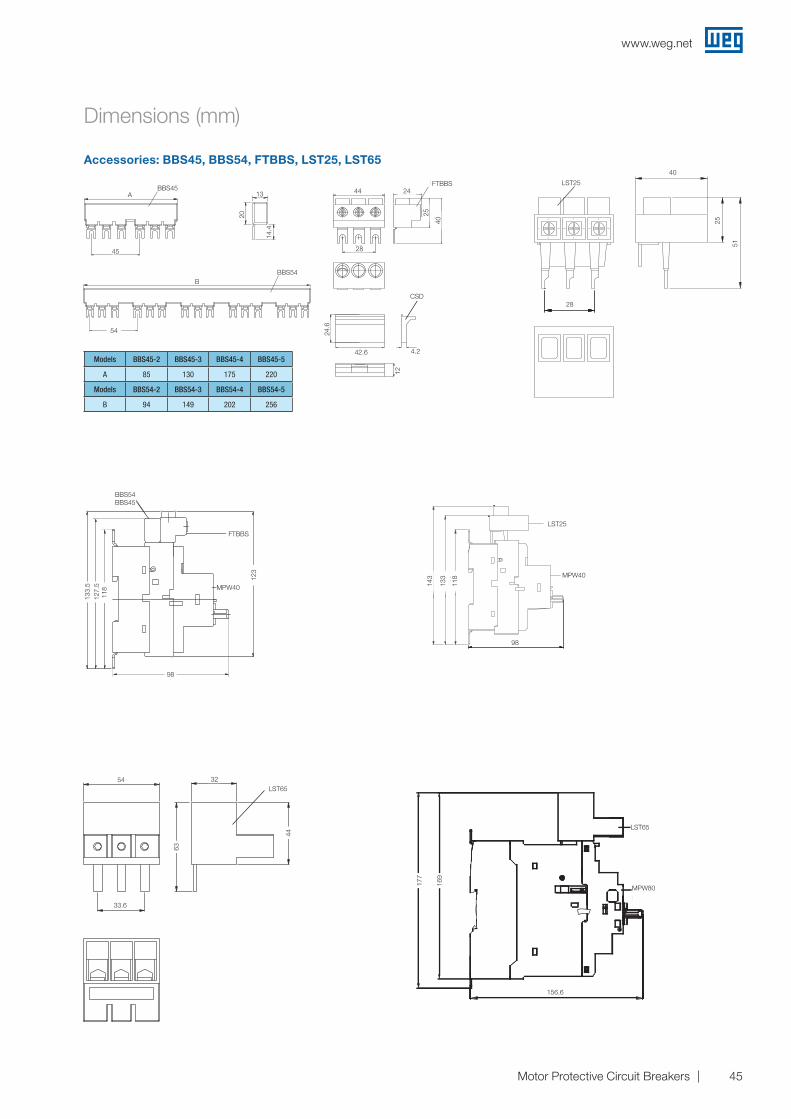
Dimensions (mm)
Accessories: BBS45, BBS54, FTBBS, LST25, LST65
Models BBS45-2 BBS45-3 BBS45-4 BBS45-5
A 85 130 175 220
Models BBS54-2 BBS54-3 BBS54-4 BBS54-5
B 94 149 202 256
FTBBS
28
MPW40
98
25
51
40
LST25
LST65
MPW80
LST65
CSD
4,242,6
24,6
12
MPW40
44
28
24
42.6
24.6
12
4.2
25
40
FTBBS
CSD
BBS54 BBS45
FTBBS
LST25
118
123
118
133
143
98
54
33.6
32
156.6
63
44
177
169
127.
513
3.5
256
54
45
A
B
45
14.4
20
13
54
BBS45
BBS54
www.weg.net
46 Motor Protective Circuit Breakers
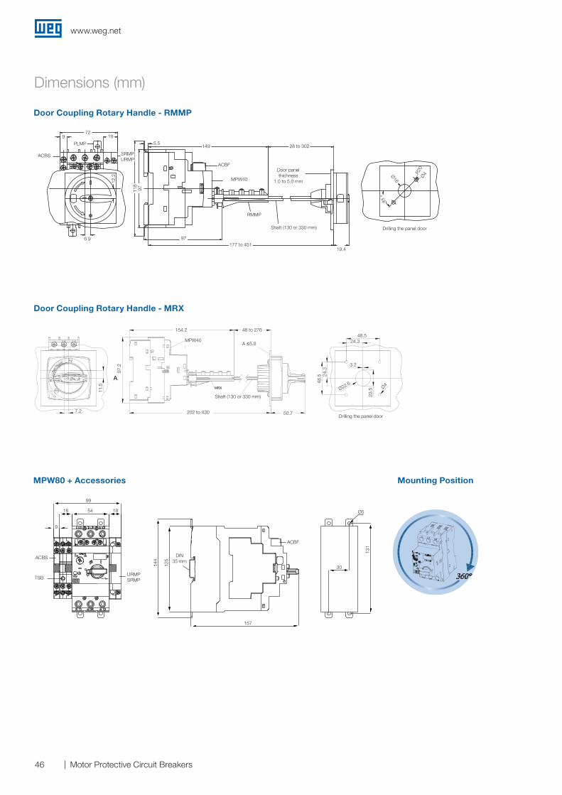
Door Coupling Rotary Handle - RMMP
Dimensions (mm)
Door Coupling Rotary Handle - MRX
MPW80 + Accessories Mounting Position
154 48 to 276
50.70
97
MRX
11.5
0
7.20
A
3.20
23,5
0 Ø4
24.25
24.2
5
48.5
0
48.50
Ø22.50
Panel door drillings
Shaft (130 or 330 mm)
A < 5.0 mmMPW25MPW25iMPW25t
202 to 430
MPW40
MPW40
131
30
∅5
157
125
144
Trilho DI35 mm
ACBF
9
99
18 54 18
URMPSRMPTSB
ACBSON
L
OFF
D
ACBS
9 18
PLMP
SRMP URMP
72
5.5149
97
19.4
45 º
Ø16
R20
Ø4
177 to 451
28 to 302
ACBF
RMMP
Door panel thichness
1.0 to 5.0 mm
Shaft (130 or 330 mm)
Shaft (130 or 330 mm)
Drilling the panel door
Drilling the panel door
6.9
118
11.5
48.5 24
.3
24.3
3.223
.5Ø22.5Ø4
48.5
97.2
7.2
ACBS
TSBURMP SRMP
DIN35 mm
99
54
157
ACBF
30
Ø5
131
18 18
144
125
9
154.2
202 to 430
48 to 276
50.7
97
12.2
A ≤5.0
www.weg.net
47Motor Protective Circuit Breakers
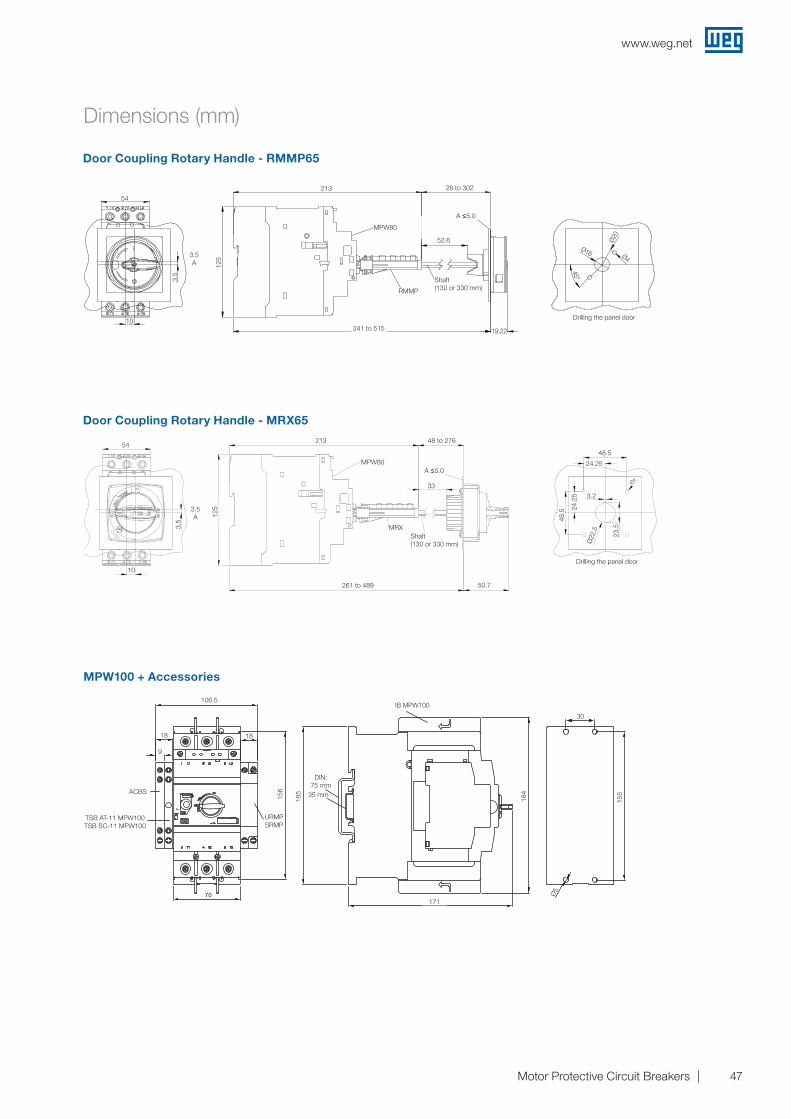
Door Coupling Rotary Handle - RMMP65
Door Coupling Rotary Handle - MRX65
Dimensions (mm)
3.50
10
54
A
50.70
213
125
33
MRX
MPW65MPW65i
23.5
0
3,20
Ø4
24.25
24.2
5
Ø22
.50
48.50
48.5
0Panel door drillings
Shaft(130 or 330mm)
A < 5.0mm
261 to 489
48 to 276
213
19.22
125
52,60
RMMP
MPW65MPW65i
3,50
10
54
B
R20
45°
Ø4
Ø16
Panel door drillings
A < 5.0mm
Shaft(130 or 330mm)
241 to 515
28 to 302
MPW100 + Accessories
165
70171
155
30
5
1818
9
106,5
35 m
Trilho DIN:75 mm
TSB AT-11 MPW100TSB SC-11 MPW100
ACBS
URMPSRMP
184
IB MPW100
156
MPW80
MPW80
213
213
106.5
156
165
184
155
Ø5
171
30
DIN: 75 mm
18
9
18
ACBS
URMP SRMP
TSB AT-11 MPW100 TSB SC-11 MPW100
10
54
10
54
125
125
3.5 A
3.5
3.5 A
3.5
28 to 302
241 to 515
261 to 489
48 to 276
33
48.5
48.5
24.25
Ø4
Ø22
.5
24.2
5
23.5
3.2
50.7
52.6
19.22
45°
Ø16 Ø4
A ≤5.0
A ≤5.0
Shaft (130 or 330 mm)RMMP
Shaft (130 or 330 mm)
MRX
Drilling the panel door
Drilling the panel door
35 mm
IB MPW100
Ø20
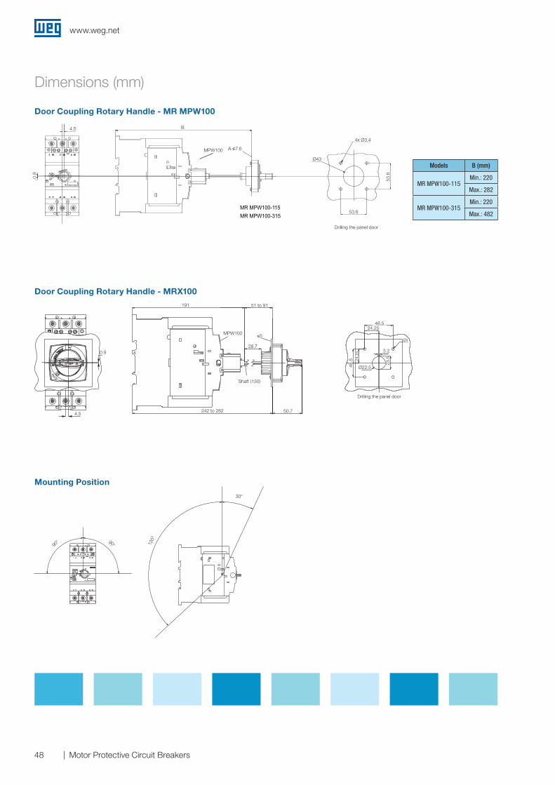
www.weg.net
48 Motor Protective Circuit Breakers
Dimensions (mm)
Door Coupling Rotary Handle - MR MPW100
Door Coupling Rotary Handle - MRX100
Models B (mm)
MR MPW100-115Min.: 220
Max.: 282
MR MPW100-315Min.: 220
Max.: 482
Mounting Position
4,5mm
0,9m
m
A < 7,6 mm
4x Ø3,4
Ø43
53,6
53,6
B
Models B (mm)
MR MPW100-115
MR MPW100-315
MR MPW100-115
min: 220max: 282
min: 220max: 482
Drilling the door drilling
MR MPW100-315
Panel door drillings
4.5 B
Ø43
53.6
53.6
0.9
0.9
191
90° 120°
30°
90°
51 to 91
242 to 282 50.7
48.524.25
3.2
Ø22.5
Ø4
24.2
5
48.5
23.5
≤5
28.7
4.5
Shaft (130)
MPW100
Drilling the panel door
Drilling the panel door
A ≤7.6 MPW100
4x Ø3.4
www.weg.net
49Motor Protective Circuit Breakers
Notes

www.weg.net
50 Motor Protective Circuit Breakers
Global presence is essential,as much as understanding your needs.
Global PresenceWith more than 30.000 employees worldwide, WEG is one of the largest electric motors, electronic equipments and systems manufacturers. We are constantly expanding our portfolio of products and services with expertise and market knowledge. We create integrated and customized solutions ranging from innovative products to complete after-sales service.
WEG’s know-how guarantees our Solutions for Solar Energy is the right choice for your application and business, assuring safety, efficiency and reliability.
Partnership is to create solutions that suits your needs
Competitive edge is to unite technology and inovation
Availability is to have a global support network
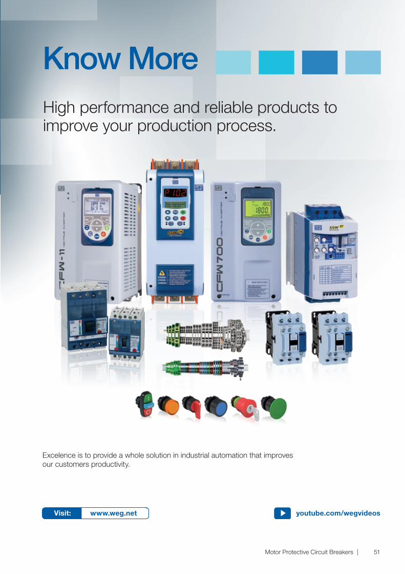
www.weg.net
51Motor Protective Circuit Breakers
Excelence is to provide a whole solution in industrial automation that improvesour customers productivity.
High performance and reliable products to improve your production process.
Know More
Visit: www.weg.net youtube.com/wegvideos
Cod
: 50
0530
62 |
Rev
: 01
| Dat
e (m
/y):
08/2
016
The
valu
es s
how
n ar
e su
bje
ct to
cha
nge
with
out p
rior
notic
e.
WEG Group - Automation Business Unit Jaraguá do Sul - SC - Brazil Phone: +55 47 3276 4000 [email protected] www.weg.net
For those countries where there is not a WEG own operation, find our local distributor at www.weg.net.
WEG Worldwide Operations
ARGENTINASan Francisco - CordobaPhone: +54 3564 [email protected]
Cordoba - CordobaPhone: +54 351 [email protected]
Buenos AiresPhone: +54 11 [email protected]
AUSTRALIAScoresby - Victoria Phone: +61 3 [email protected]
AUSTRIAMarkt Piesting - Wiener Neustadt-LandPhone: +43 2633 [email protected]
BELGIUMNivelles - BelgiumPhone: +32 67 [email protected]
BRAZILJaraguá do Sul - Santa CatarinaPhone: +55 47 [email protected]
CHILELa Reina - SantiagoPhone: +56 2 [email protected]
CHINANantong - JiangsuPhone: +86 513 [email protected]
Changzhou – Jiangsu Phone: +86 519 [email protected]
COLOMBIASan Cayetano - BogotaPhone: +57 1 [email protected]
ECUADOREl Batan - QuitoPhone: +593 2 [email protected]
FRANCESaint-Quentin-Fallavier - IsèrePhone: +33 4 [email protected]
GERMANYTürnich - Kerpen Phone: +49 2237 [email protected]
Balingen - Baden-WürttembergPhone: +49 7433 [email protected]
Homberg (Efze) - HessePhone: +49 5681 [email protected]
GHANAAccraPhone: +233 30 [email protected]
INDIABangalore - KarnatakaPhone: +91 80 [email protected]
Hosur - Tamil NaduPhone: +91 4344 [email protected]
ITALYCinisello Balsamo - MilanoPhone: +39 2 [email protected]
JAPANYokohama - KanagawaPhone: +81 45 [email protected]
MALAYSIAShah Alam - SelangorPhone: +60 3 [email protected]
MEXICOHuehuetoca - MexicoPhone: +52 55 [email protected]
Tizayuca - HidalgoPhone: +52 77 97963790
NETHERLANDSOldenzaal - OverijsselPhone: +31 541 [email protected]
PERULa Victoria - LimaPhone: +51 1 [email protected]
PORTUGALMaia - PortoPhone: +351 22 [email protected]
RUSSIA and CISSaint PetersburgPhone: +7 812 363 [email protected]
SOUTH AFRICAJohannesburgPhone: +27 11 [email protected]
SPAINCoslada - MadridPhone: +34 91 [email protected]
SINGAPORESingaporePhone: +65 [email protected]
SingaporePhone: +65 [email protected]
SCANDINAVIAMölnlycke - SwedenPhone: +46 31 [email protected]
UKRedditch - WorcestershirePhone: +44 1527 [email protected]
UNITED ARAB EMIRATESJebel Ali - DubaiPhone: +971 4 [email protected]
USADuluth - GeorgiaPhone: +1 678 [email protected]
Minneapolis - MinnesotaPhone: +1 612 3788000
VENEZUELAValencia - CaraboboPhone: +58 241 [email protected]