Embed Size (px)
Citation preview

MOTOR PROTECTION RELAYS
for
Total Peace of Mind

1
Switchgear Factory, Ahmednagar
Switchgear Factory, Vadodara
Switchgear Factory, Navi Mumbai
L&T Switchgear, a part of the Electrical &
Automation business, is India's largest
manufacturer of low voltage switchgear, with
the scale, sophistication and range to meet
global benchmarks. With over five decades of
experience in this field, the Company today
enjoys a leadership position
in the Indian market with a growing
international presence.
It offers a complete range of products
including powergear, controlgear, industrial
automation, building electricals & automation,
reactive power management, energy meters,
and protective relays. These products conform
to Indian and International Standards.
L&T limited offers a wide range of Numerical
relays suitable for LV & MV power distribution
systems. These relays are manufactured at
L&T ‘s Mysore works equipped with modern
infrastructure and employing latest
manufacturing and testing equipment.
The selection of Motor Protection System
should be based on the cost and
application of the electric motor. Its
appropriate selection not only prevents
motor damage, but also ensures optimal
process efficiency with minimal
interruption.
Pick the motor protection relay that
meets your needs:
MPR200nX / Mini Motor Protection Relay
MM10 Compact Motor Protection Relay
MM30 Comprehensive Motor Protection Relay
MCOMP Intelligent Motor Control, Monitoring and Protection Relay
Appendix iArticle on fail-safe & non fail-safe logic
Appendix iiProduct selection Guide
MPR300
Index
2
4
6
8
Nos.
Larsen & Toubro is a
technology-driven company
that infuses engineering with
imagination. The Company
offers a wide range of
advanced solutions in the field
of Engineering, Construction,
Electrical & Automation,
Machinery and Information
Technology.
12
13
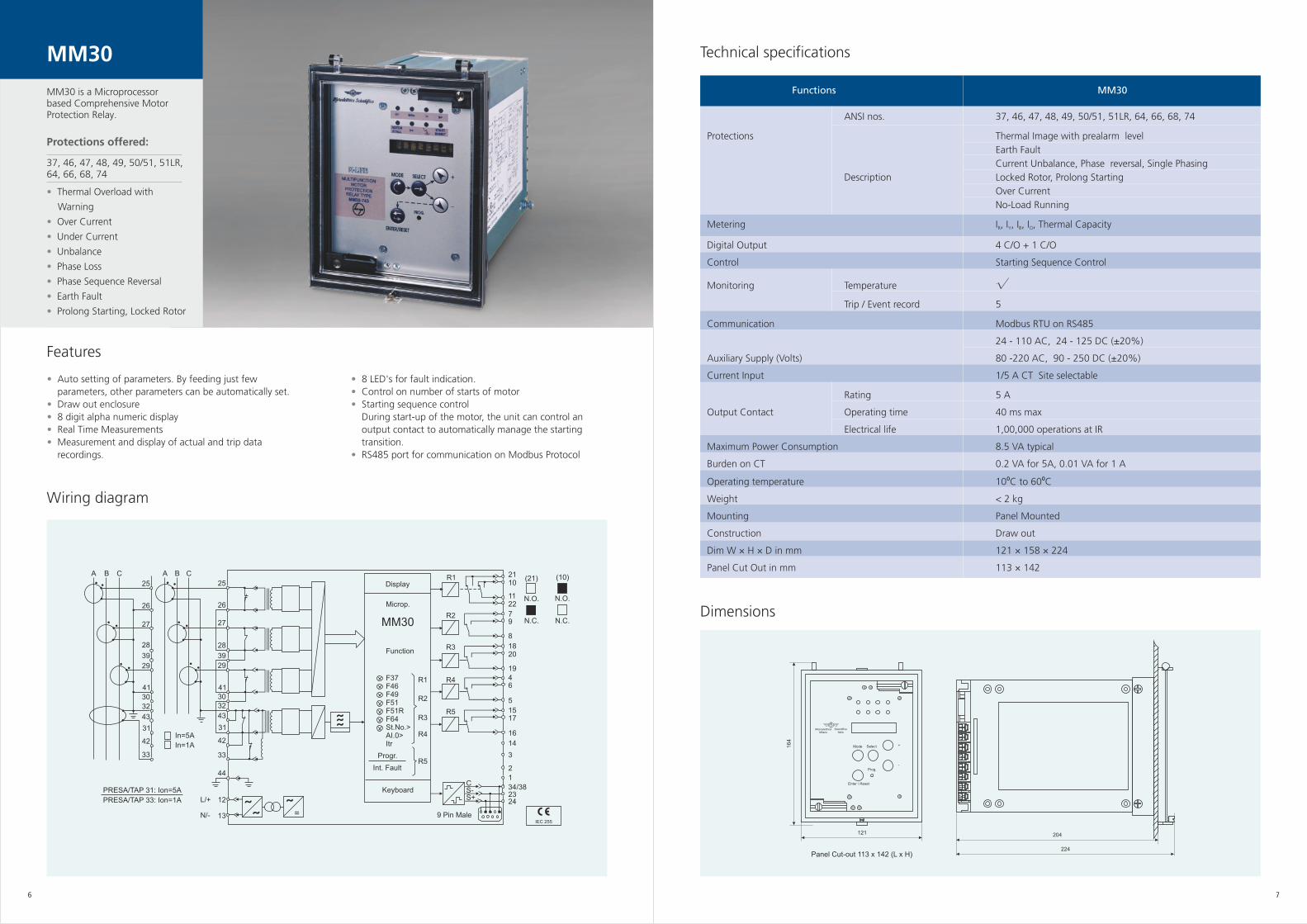
Technical specifications
Wiring diagram
MPR200nX /MPR300
Dimensions
Application Features•
•
These relays are used for protection of motors widely usedin fans pumps, crushers, mills, compressors, beltconveyors, centrifuges, mixers, ventilators, escalators, motorized valves etc.
MPR 300 offers you greater security, operator safetythrough proper co-ordination in case of earth fault onmotor feeder.
•••••
LED's for trip indication.4 selectable trip time curves for thermal overloadTest facility through front push button.Manual reset facility through front push button.With / Without fail safe mode.*
Parameters MPR200nX / MPR300
ANSI nos. 49, 51LR, 37, 64*, 46
Protections Description Thermal overload, Earth fault*, Single Phasing, Locked rotor,
Under Current, Current Unbalance, Phase sequence reversal
Current range 1 - 88 A
Overload trip class 10A, 10, 20, 30
Auxiliary power supply 240 V AC +/- 20%
110V AC +/-20%
Contacts 1 N/O + 1 N/C – manual reset
Rated Voltage 250 V AC / 30 V DC
Contact Ratings Rated Current 5A
Rated breaking capacity 2000 VA / 240 W(Resistive)
Dimensions (W x H x D) in mm 70 x 85 x 106
Mounting DIN Rail
Weight < 400 grams
Operating Temperature 0 to 60 deg. C
Accuracy As per IEC 947-4-1
Reference Standards IEC 60255, IEC 61000 and IEC 60068
106
85
35.5
42.6 16
R
Y
B
70
Ø12 - 3 Places
M
1 2 3 4 5 6 7 8
NC NO
MPR200nX / MPR300
AuxSupply
R Y B N
StartN/O
Stop(N/C)
Typical connection diagramfor ‘Direct Starting’ application
Aux. N/O
R
Y
B
N
Fuse
ReverseContactor
ForwardContactor
3Ø Motor
In case of reversible starters;MPR200nX / MPR300 must be placed before the reversing contactors.
Line Contactor
DeltaContactor
StarContactor
3Ø Motor
R
Y
B
N
Fuse
MPR200nX / MPR300in case of star Delta Starter
0 must sense Line Current
MPR200nX / MPR300 is a microcontroller based LT Motor protection relay. The relay has got inbuilt CTs for motor sizes up to 50KW (i.e. 88 A current)
Protections offered:
49, 51LR, 37, 64*, 46
•
•
•
•
•
•
Thermal Overload
Earth Fault (MPR300 only)
Single Phasing,
Current unbalance
Phase sequence reversal
Locked Rotor
Under Current
2 3
* Available only in MPR300
New
*Model with fail-safe logic is available on request. For technical info on fail-safe logic refer Appendix i
Functions
Technical specifications
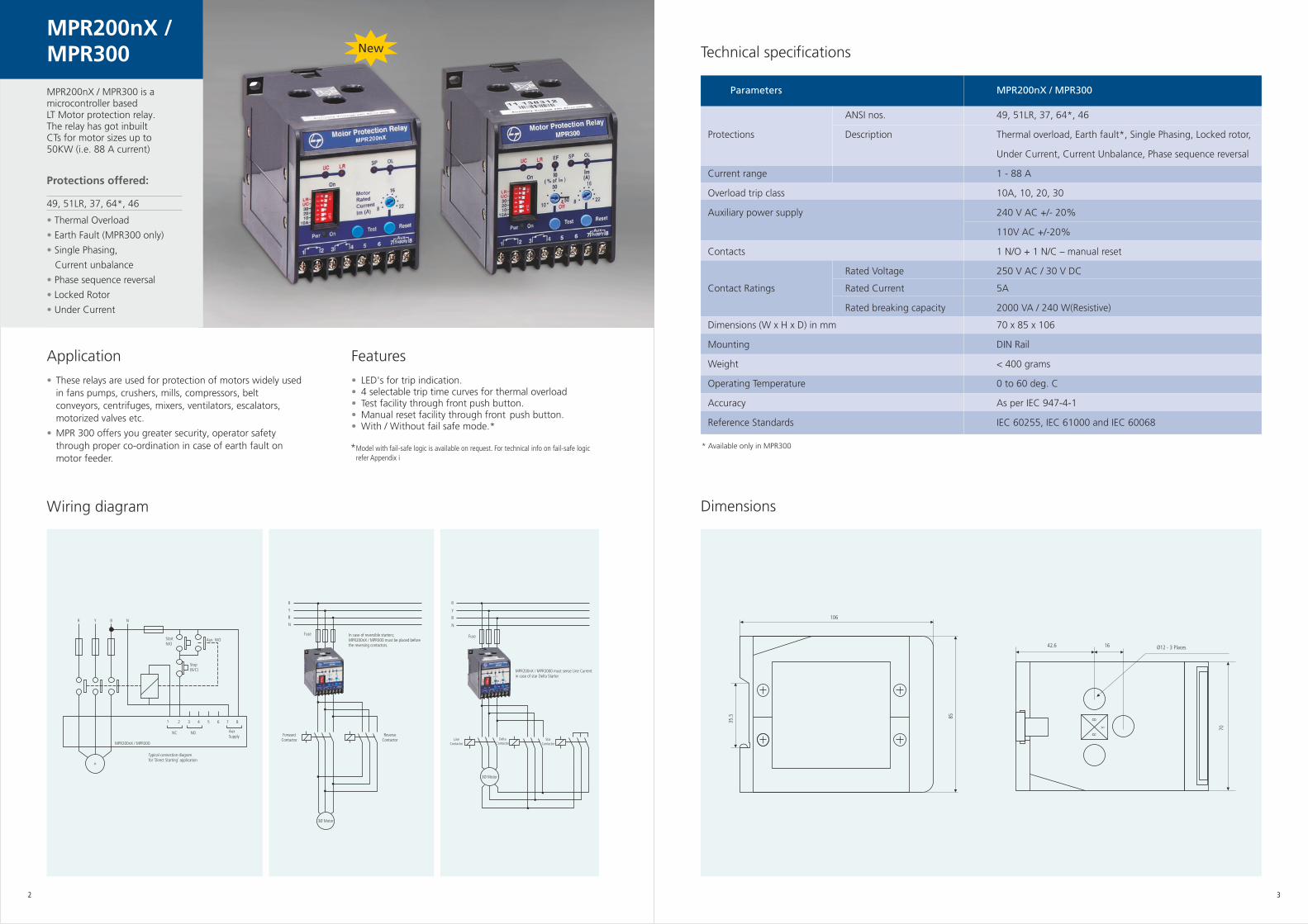
MM10
Wiring diagram
••
•
•
•
4 Digit LED displayMeasurement of RYB, Zero Sequence current and Thermal capacity.Separate LED's for indication of Motor operational, Trip &Thermal OL/ pre-alarm status.Programmable thermal OL time constant right from 1 sec to 40 sec.2 nos. of C/O output contacts.The relay 2 output is programmable type. It can be configured for following conditions:
I) On any tripping ii) On thermal tripping iii) On thermal Warning
•
•
•
•
Relay output ‘R1‘ works with fail-safe logic. For technical info on fail-safe logic, refer Appendix I1 no. Programmable Binary input for remote operation.It can be configured for either of these operations:I) Inhibit Motor Start ii) Trip Reset iii) Instant TrippingRelay testing facility Test push button to check working of relay contacts.Trip data recordingFault current or cause of last trip is displayed.
9 1
10 2
11 3
12 4
13 5
14 6
15 7
16 8
R1
R2NC
NO
COM
COM
NC
NO
N
L
BinaryInput
MM10
Aux
Bloack R1/Reset/ Trip
F1 F2 F3
L1L2L3 F4
K1
Protectionclass CT’S
M H1K1
K1
S2
S1
Stop
Start
N
External CT's - Protection class CT's [5 - 1000 Amps] with 5 Amp secondary
ANSI nos. 37, 46, 49, 50/ 51, 51LR, 64
Protections Description Thermal Overload With Warning, Short Circuit, Under Current, Unbalance, Phase Loss, Phase Sequence Reversal, Earth Fault, Prolong Starting, Locked Rotor
Metering I , I , I , I , Thermal CapacityR Y B O
Digital Input + Output 1 DI + 2 CO Type DO
Monitoring Last 1 Trip
Auxiliary Supply 110 - 240 V AC/DC
Current Input 5 A CT secondary
Binary Input Voltage Rating 12 V supplied internally
Rating 5 A, 250 VAC (cosφ = 1)
Output Contact Operating time 15 ms Max
Electrical life 1,00,000 Operations at IR
6Mechanical life 5 x 10 Operations
Maximum Power Consumption 3 VA typical
Burden on CT 0.3 VA at Rated Current
Operating Temperature -5⁰C to +55⁰C
Degree of Protection IP52
Weight 0.75 Kg
Mounting Panel Mounted
Dim W×H×D in mm 96 × 96 × 110
Panel Cut Out in mm 90 × 90
Dimensions
Front
96 mm
96 m
m
100 mm
110 mm
SidePanel Cutout
90 mm
90 m
m
Features
4 5
MM10
MM10 is a Compact Microprocessor based Motor Protection Relay for medium and large size Motors
Protections offered:
37, 46, 49, 50/ 51, 51LR, 64
•
• • • • • • •
Thermal Overload With Warning
Under CurrentUnbalancePhase LossPhase Sequence ReversalEarth FaultProlong Starting, Locked RotorShort Circuit
Functions
Technical specifications
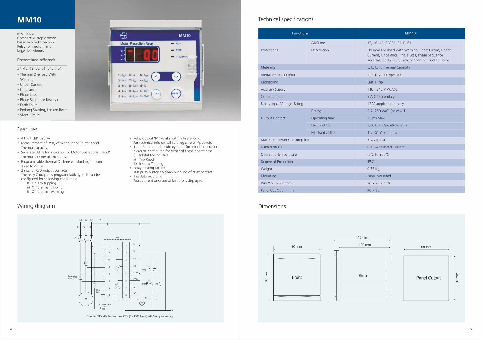
MM30
Wiring diagram
•
••••
Auto setting of parameters. By feeding just fewparameters, other parameters can be automatically set.Draw out enclosure8 digit alpha numeric displayReal Time MeasurementsMeasurement and display of actual and trip datarecordings.
Features
•••
•
8 LED's for fault indication.Control on number of starts of motorStarting sequence control During start-up of the motor, the unit can control anoutput contact to automatically manage the starting transition.RS485 port for communication on Modbus Protocol
Dimensions
L/+
N/-
A B C A B C
25
26
27
28
29
41
30
32
39
25
26
27
28
39
29
413032
43
31
42
33
43
31
42
33
44
In=1A
In=5A
PRESA/TAP 31: Ion=5A
PRESA/TAP 33: Ion=1A 12
13 ˜˜
˜
˜̃̃
=
Display
Microp.
MM30
Function
F37F46F49F51F51RF64St.No.>AI.0>Itr
Progr.
Int. Fault
Keyboard
R1
R2
R3
R4
R5
R1
R2
R3
R4
R5
9 Pin Male
(21) (10)
N.O. N.O.
N.C. N.C.
2110
1122
79
8
1820
1946
5
1517
16
14
3
2
1
34/382324
CS-S+
IEC 255
ANSI nos. 37, 46, 47, 48, 49, 50/51, 51LR, 64, 66, 68, 74
Protections Thermal Image with prealarm level Earth Fault
Current Unbalance, Phase reversal, Single PhasingDescription Locked Rotor, Prolong Starting
Over CurrentNo-Load Running
Metering I , I , I , I , Thermal CapacityR Y B O
Digital Output 4 C/O + 1 C/O
Control Starting Sequence Control
Monitoring Temperature √Trip / Event record 5
Communication Modbus RTU on RS485
24 - 110 AC, 24 - 125 DC (±20%)
Auxiliary Supply (Volts) 80 -220 AC, 90 - 250 DC (±20%)
Current Input 1/5 A CT Site selectable
Rating 5 A
Output Contact Operating time 40 ms max
Electrical life 1,00,000 operations at IR
Maximum Power Consumption 8.5 VA typical
Burden on CT 0.2 VA for 5A, 0.01 VA for 1 A
Operating temperature 10⁰C to 60⁰C
Weight < 2 kg
Mounting Panel Mounted
Construction Draw out
Dim W × H × D in mm 121 × 158 × 224
Panel Cut Out in mm 113 × 142
164
121
Panel Cut-out 113 x 142 (L x H)
204
224
MicroelettricaMilano
ScientificaItalia
Mode Select
Prog.
Enter / Reset
+
-
6 7
MM30 is a Microprocessor based Comprehensive Motor Protection Relay.
Protections offered:
37, 46, 47, 48, 49, 50/51, 51LR, 64, 66, 68, 74
•
•
•
•
•
•
•
•
Thermal Overload with
Warning
Over Current
Under Current
Unbalance
Phase Loss
Phase Sequence Reversal
Earth Fault
Prolong Starting, Locked Rotor
MM30
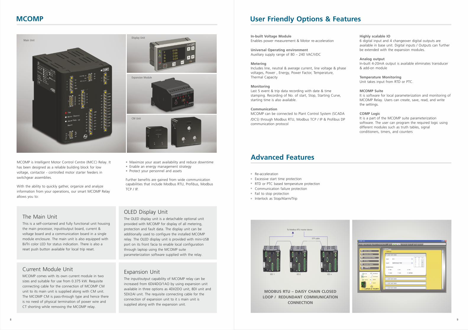
MCOMP
Main Unit Display Unit
Expansion Module
CM Unit
MCOMP is Intelligent Motor Control Centre (IMCC) Relay. It has been designed as a reliable building block for low voltage, contactor - controlled motor starter feeders in switchgear assemblies.
With the ability to quickly gather, organize and analyze information from your operations, our smart MCOMP Relay allows you to:
•••
Maximize your asset availability and reduce downtimeEnable an energy management strategyProtect your personnel and assets
Further benefits are gained from wide communicationcapabilities that include Modbus RTU, Profibus, Modbus TCP / IP.
This is a self-contained and fully functional unit housing the main processor, input/output board, current & voltage board and a communication board in a single module enclosure. The main unit is also equipped with Bi/Tri color LED for status indication. There is also a reset push button available for local trip reset.
The Main Unit OLED Display UnitThe OLED display unit is a detachable optional unit provided with MCOMP for display of all metering, protection and fault data. The display unit can be additionally used to configure the installed MCOMP relay. The OLED display unit is provided with mini-USB port on its front facia to enable local configuration through laptop using the MCOMP suite parameterization software supplied with the relay.
The input/output capability of MCOMP relay can be increased from 6DI/4DO/1AO by using expansion unit available in three options as 4DI/2DO unit, 8DI unit and 5DI/2AI unit. The requisite connecting cable for the connection of expansion unit to it s main unit is supplied along with the expansion unit.
Expansion Unit MCOMP comes with its own current module in two sizes and suitable for use from 0.375 kW. Requisite connecting cable for the connection of MCOMP CM unit to its main unit is supplied along with CM unit. The MCOMP CM is pass-through type and hence there is no need of physical termination of power wire and CT shorting while removing the MCOMP relay.
Current Module Unit
User Friendly Options & Features
In-built Voltage Module
Universal Operating environment
Metering
Monitoring
Communication
Enables power measurement & Motor re-acceleration
Auxiliary supply range of 80 – 240 VAC/VDC
Includes line, neutral & average current, line voltage & phasevoltages, Power , Energy, Power Factor, Temperature,Thermal Capacity
Last 5 event & trip data recording with date & timestamping. Recording of No. of start, Stop, Starting Curve,starting time is also available.
MCOMP can be connected to Plant Control System (SCADA
/DCS) through Modbus RTU, Modbus TCP / IP & Profibus DPcommunication protocol
Highly scalable IO
Analog output
Temperature Monitoring
MCOMP Suite
COMP Logic
6 digital input and 4 changeover digital outputs areavailable in base unit. Digital inputs / Outputs can furtherbe extended with the expansion modules.
In-built 4-20mA output is available eliminates transducer& add-on module
Unit takes input from RTD or PTC.
It is software for local parameterization and monitoring ofMCOMP Relay. Users can create, save, read, and writethe settings.
It is a part of the MCOMP suite parameterizationsoftware. The user can program the required logic usingdifferent modules such as truth tables, signalconditioners, timers, and counters
To Modbus RTU master device
IED 1 IED2
STP cable
MODBUS RTU – DAISY CHAIN CLOSED LOOP / REDUNDANT COMMUNICATION
CONNECTION
IED n
8 9
Advanced Features
Re-accelerationExcessive start time protectionRTD or PTC based temperature protectionCommunication failure protectionFail to stop protectionInterlock as Stop/Alarm/Trip
Protection
MCOMP provides all basic current, voltage and frequency protection. It also provides motor-specific protection like locked rotor, number of starts, excessive start time, phase reversal and phase loss. It distinguishes between starting and running condition, and provides appropriate protection at the right time. It continuously monitors motor thermal capacity and trips the motor in case the thermal capacity gets consumed. It does not allow the motor to start unless
thermal capacity is below the requisite safe threshold level. All protections are defined to cover the widest conceivable range of applications.
MCOMP can also provide earth fault protection and sensitive earth fault protection. Sensitive earth fault protection is provided through an external CBCT. The table below shows the setting range of protection available in MCOMP.
PROTECTION FUNCTION ANSI CODE VARIABLE RANGEThermal Overload 49 Pick Up 20 - 100% Iset
Alarm 80 - 100% TMUnder Current 37P Pick Up 30 – 85% Ir
Alarm 110% of pick upTrip Delay 1 – 120 Sec
Over Current 50P Pick Up 50 – 1000% IflcAlarm 90% of pick upTrip Delay 0.1 – 10 Sec
Time Delayed Phase 51P Pick Up 20 – 1000% IflcOvercurrent Alarm 90% of pick up
Time Constant 0.5 – 600 SecIEC Curves Inverse, Very Inverse, Extremely Inverse
Time Delayed Neutral 51N Pick Up 20 – 1000% IflcOvercurrent Alarm 90% of pick up
Time Constant 0.5 – 600 SecIEC Curves Inverse, Very Inverse, Extremely Inverse
Locked Rotor 50LR Pick Up 150 – 1000% IflcAlarm 90% of pick upTrip Delay 0.5 – 30 Sec
Current Unbalance 46 Pick Up 5 – 100% IflcAlarm 85 - 100% of pick upTrip Delay 1 – 30 Sec
Phase Loss 47a Trip Delay 0.1 – 30 SecEarth Fault 50N Pick Up 20 – 500% Iflc(Vector Summation) Alarm 90% of pick upOR Trip Delay 0.5 – 30 SecSensitive Earth Fault 50SG Pick Up 0.1 – 20 A(Through CBCT) Alarm 0.1 - 20 A
Trip Delay 0.5 – 30 SecUnder Voltage 27 Pick Up 20 – 85% Vn
Alarm 110% of pick upTrip Delay 0.2 – 25 Sec
Over Voltage 59 Pick Up 101 – 130% VnAlarm 95% of pick upTrip Delay 0.2 – 25 Sec
Voltage Unbalance 47 Pick Up 5 – 50% VnAlarm 90% of pick upTrip Delay 0.2 – 20 Sec
Under Frequency 81L Pick Up 94 – 98% FsAlarm 101% of pick upTrip Delay 1 – 30 Sec
Over Frequency 81H Pick Up 101 – 105% FsAlarm 99% of pick upTrip Delay 1 – 30 Sec
Phase Reversal 47b Sequence RYB or RBYMaximum Number 66 Reference Period 15 – 60 Minof Starts Permissive Starts 1 – 30
Inhibit Period 1 – 120 Min
10 11
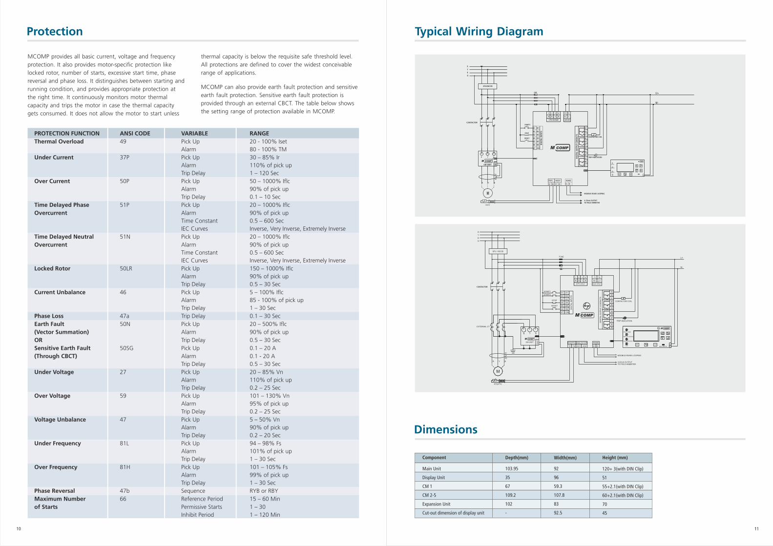
Typical Wiring Diagram
Dimensions
Component
Main Unit
Display Unit
CM 1
CM 2-5
Expansion Unit
Cut-out dimension of display unit
Depth(mm)
103.95
35
67
109.2
102
-
Width(mm)
92
96
59.3
107.8
83
92.5
Height (mm)
120+ 3(with DIN Clip)
51
55+2.1(with DIN Clip)
60+2.1(with DIN Clip)
70
45
R Y B
CBCT
M
SFU/MCCB
R Y B
FUSE
S1
S2
4-20mA OUTPUTTO FIELD AMMETER
MODBUS RS485 LOOPING
L/+
N/-
START1
STOP
RESETCONTACTOR COIL
TRIP INDICATION
RTD/PTC
2 4 6
1 3 5CONTACTOR
N/- L/+
1 2 3 4
61
62
63
64
65
66
67
DI1
DI2
DI3
DI4
DI5
DI6
COM
DIG
ITA
L IN
PUTS
N B Y R
3-PH.VOLTAGE
85
89
87
88
92
90
91
82
83
81
86
84
DIG
ITA
L O
UTP
UT
CON
TACT
S
71 72
AUX.VOLT
PWR/COMM
MOTOR STATUS
ALARM/PICKUP
TRIPRST ENT
NL
ANALOG O/PRTD/PTC
D+
RS485
53 56 51 54 D-
CM UNIT
RYBN
S1
S2
4-20mA OUTPUT
MODBUS RS485 LOOPING
TO FIELD AMMETER
STOP
RESET
CONTACTOR COIL
TRIP INDICATION
RTD/PTC
1 2 3 4
61
62
63
DI2
64
67
DI1
66 DI6
65
DI4
DI5
DIG
ITA
L I
NP
UT
S
DI3
N Y R
84
88
B
89
91
92
87
90
81
86
83
85
72
DIG
ITA
L O
UT
PU
T C
ON
TA
CT
S
82
RS485
71
PWR/COMM
MOTOR STATUS
TRIP
ALARM/PICKUP
RST ENTL
Mini USB Port N
M
COM
RTD/PTC
D+
R
D-
ANALOG O/P
L/+
Y B
FUSE
N/-
AUX.VOLT3-PH.VOLT
L/+
N/-
START2
START1
TI2 AO2AO1TI1
MCOMP
CB
CT
CM UNIT
B Y R
SFU / MCCB
R
Y
B
N
EXTERNAL CT
MCOMP
MCOMP
2 4 6
1 3 5CONTACTOR
Appendix i Appendix ii
12
Parameters Model
Category Sub-Category MPR200nX / MM10 MM30 MCOMP
MPR300
General Display × 4 Digit LED Alphanumeric
Display Display Display
Current Input CT Sec. Inbuilt CT 5A 1 / 5A site Its own CT
up to 88A selectable unit up to 80A
Thermal O/L (49) ü ü ü ü
Earth Fault (51N / 64) ü (MPR300 only) ü ü ü
Phase reversal ü ü ü ü
Phase unbalance (46) ü ü ü ü
Single Phasing ü ü ü ü
Locked rotor protection(51LR) ü ü ü ü
Protection Under current (37P) ü ü ü ü
Overcurrent (51) x ü ü ü
Max. no. of starts(66) x x ü ü
Short circuit (50) x ü ü x
Sensitive Ground (50/51SG) x x x ü
Frequeny (81O/U) x x x ü
Voltage (27P/59P) x x x ü
Input+Output Basic 2 DO 1 DI+2 DO 4 DO 6 DI+4 DO
Expandability options x x x ü
Metering Current x ü ü ü
V, f , power, energy x x x ü
Monitoring Trip / Event record × 1 5 5/5
Communication Modbus RTU x x ü ü
Modbus TCP/IP, Profibus x x x ü
4 line OLED
× - Not available - Available ü
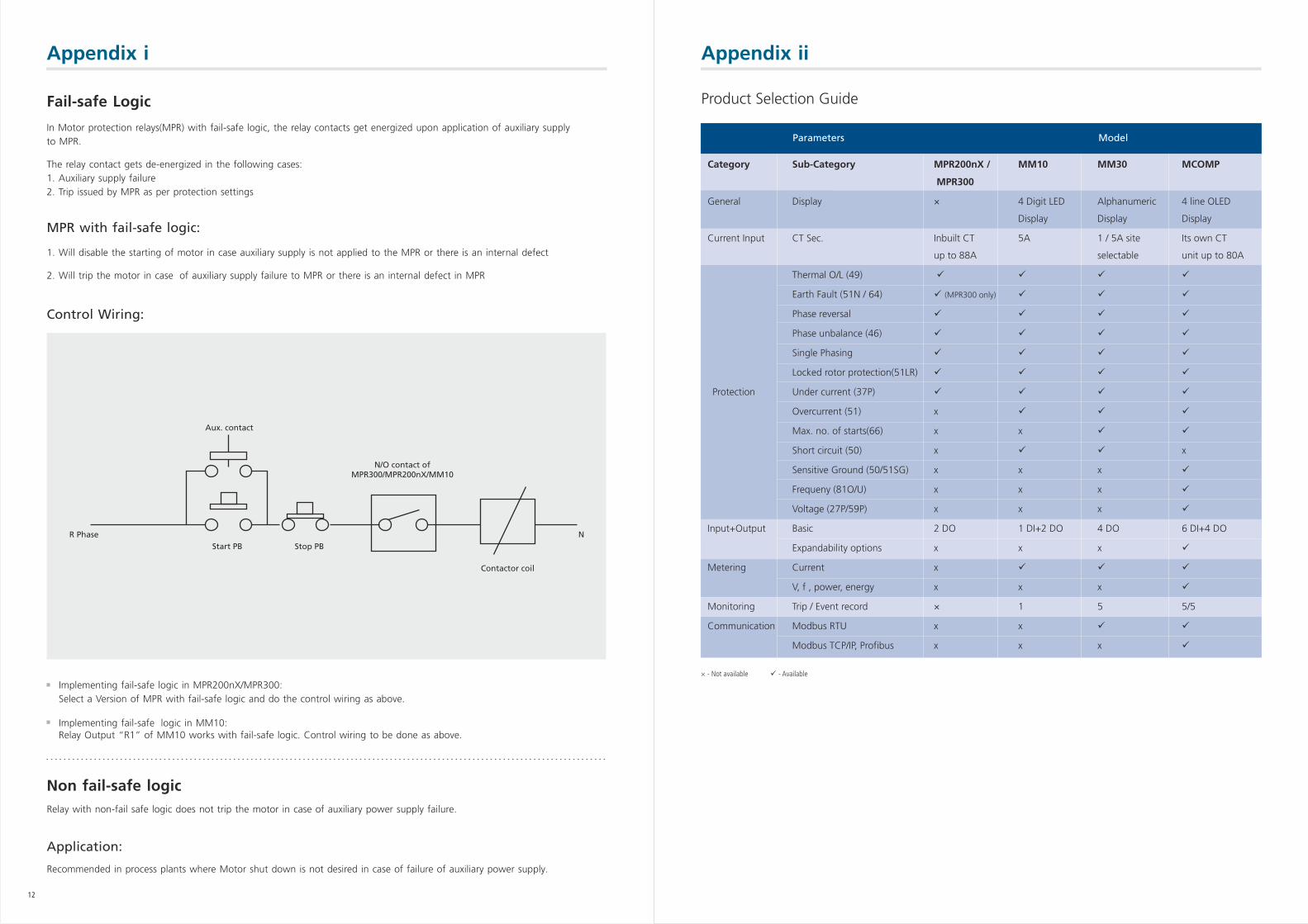
Product Selection GuideFail-safe Logic
In Motor protection relays(MPR) with fail-safe logic, the relay contacts get energized upon application of auxiliary supply to MPR.
The relay contact gets de-energized in the following cases:1. Auxiliary supply failure2. Trip issued by MPR as per protection settings
MPR with fail-safe logic:
1. Will disable the starting of motor in case auxiliary supply is not applied to the MPR or there is an internal defect
2. Will trip the motor in case of auxiliary supply failure to MPR or there is an internal defect in MPR
Control Wiring:
Implementing fail-safe logic in MPR200nX/MPR300:Select a Version of MPR with fail-safe logic and do the control wiring as above.
Implementing fail-safe logic in MM10:Relay Output “R1” of MM10 works with fail-safe logic. Control wiring to be done as above.
N/O contact ofMPR300/MPR200nX/MM10
Aux. contact
R Phase NStart PB Stop PB
Contactor coil
Non fail-safe logicRelay with non-fail safe logic does not trip the motor in case of auxiliary power supply failure.
Application:
Recommended in process plants where Motor shut down is not desired in case of failure of auxiliary power supply.
Customer Interaction Center (CIC)BSNL / MTNL (toll free): 1800 233 5858 Reliance (toll free): 1800 200 5858 Tel: 022 6774 5858 Fax: 022 6774 5859 Email: [email protected] Web: www.Lntebg.com
Larsen & Toubro Limited, Electrical Standard ProductsPowai Campus, Mumbai 400 072
Regd. Office: L&T House, N. M. Marg, Ballard Estate, Mumbai - 400 001, INDIA. CIN: L99999MH1946PLC004768
CB
MC
/PR
D/0
72016
SP
50576R
1
Khairasol, Degaul AvenueDurgapur 713 212Tel: 0343-2540448 / 2540449 / 2540443Fax: 0343-2540442e-mail: [email protected]
5, Milanpur Road, Bamuni MaidanGuwahati 781 021Tel: +91 8876554410 / 8876554417Fax: 361-2551308e-mail: [email protected]
II Floor, Vasantha Chambers5-10-173, Fateh Maidan RoadHyderabad 500 004Tel: 040-67015052Fax: 040-23296468e-mail: [email protected]
Monarch Building, 1st FloorD-236 & 237, Amrapali MargVaishali NagarJaipur 302 021Tel: 0141-4385914 to 18Fax: 0141-4385925e-mail: [email protected]
Akashdeep Plaza, 2nd FloorP. O. GolmuriJamshedpur 831 003JharkhandTel: 0657-2312205 / 38Fax: 0657-2341250e-mail: [email protected]
Skybright Bldg; M. G. RoadRavipuram Junction, ErnakulamKochi 682 016Tel: 0484-4409420 / 4 / 5 / 7Fax: 0484-4409426e-mail: [email protected]
3-B, Shakespeare SaraniKolkata 700 071Tel: 033-42005982Fax: 033-22821025 / 7587e-mail: [email protected]
A28, Indira Nagar, Faizabad Road Lucknow 226 016Tel: 0522-4929905 / 04Fax: 0522-2311671e-mail: [email protected]
No: 73, Karpaga Nagar, 8th StreetK. PudurMadurai 625 007Tel: 0452-2567405 / 2561068 / 2561657Fax: 0452-2567552e-mail: [email protected]
Electrical Standard Products (ESP) Offices:
HEAD OFFICEL&T Business Park,Tower 'B' / 3rd FloorSaki Vihar Road, PowaiMumbai 400 072Tel: 022-67053229 Fax: 022-67051112e-mail: [email protected]
BRANCH OFFICES501, Sakar Complex I Opp. Gandhigram Rly. Station Ashram RoadAhmedabad 380 009Tel: 079-66304006-11Fax: 079-66304025e-mail: [email protected]
38, Cubbon Road, P. O. Box 5098Bengaluru 560 001Tel: 080-25020100 / 25020324Fax: 080-25580525e-mail: [email protected]
131/1, Zone IIMaharana Pratap NagarBhopal 462 011Tel: 0755-3080511 / 05 / 08 / 13 / 17 / 19 Fax: 0755-3080502e-mail: [email protected]
Plot No. 559, Annapurna ComplexLewis RoadBhubaneswar 751 014Tel: 0674-6451342 / 2436690 / 2436696Fax: 0674-2537309e-mail: [email protected]
Aspire Towers, 4th FloorPlot No. 55, Phase-IIndustrial & Business ParkChandigarh-160 002Tel: 0172-4646840 / 41 / 42 / 46 / 53Fax: 0172-4646802Email: [email protected]
L&T Construction CampusTC-1 Building, II FloorMount-Poonamallee RoadManapakkamChennai 600 089Tel: 044-2270 6800Fax: 044-22706940e-mail: [email protected]
67, Appuswamy RoadPost Bag 7156 Opp. Nirmala CollegeCoimbatore 641 045Tel: 0422-2588120 / 1 / 5Fax: 0422-2588148e-mail: [email protected]
L&T Business Park,Tower 'B' / 5th FloorSaki Vihar Road, PowaiMumbai 400 072Tel: 022-67052874 / 2737 / 1156Fax: 022-67051112e-mail: [email protected]
12, Shivaji NagarNorth Ambajhari RoadNagpur 440 010Tel: 0712-2260012 / 6606421Fax: 2260030 / 6606434e-mail: [email protected]
32, Shivaji Marg P. O. Box 6223New Delhi 110 015Tel: 011-41419514 / 5 / 6Fax: 011-41419600e-mail: [email protected]
L&T House P. O. Box 119 191/1, Dhole Patil RoadPune 411 001Tel: 020-66033395 / 66033279Fax: 020-26164048 / 26164910e-mail: [email protected]
Crystal Tower, 4th Floor, G. E. RoadTelibandhaRaipur - 492 006Tel: 0771-4283214e-mail: [email protected]
3rd Floor Vishwakarma ChambersMajura Gate, Ring RoadSurat 395 002Tel: 0261-2473726Fax: 0261-2477078e-mail: [email protected]
Radhadaya ComplexOld Padra RoadNear Charotar SocietyVadodara 390 007Tel: 0265-6613610 / 1 / 2Fax: 0265-2336184e-mail: [email protected]
Door No. 49-38-14/3/2, 1st floor,NGGO's Colony, Akkayyapalem,Visakhapatnam - 530 016Tel: 0891-2791126 / 2711125Fax: 0891-2791100e-mail: [email protected]