Embed Size (px)
DESCRIPTION
Motor Drive. Dr. Ahmad Harb. Modern Variable Speed System. A modern variable speed system has four components: 1. Electric Motor 2. Power Converter - Rectifiers - Choppers - Inverters - Cycloconverters. - PowerPoint PPT Presentation
Citation preview

Motor DriveMotor Drive
Dr. Ahmad Harb

Modern Variable Speed System
A modern variable speed system has four components:
1. Electric Motor 2. Power Converter - Rectifiers - Choppers - Inverters - Cycloconverters

Modern Variable Speed System (Contd’)
3. Controllers – matching the motor and power converter to meet the load requirements
4. Load

Electric Motors
• Types of electric motors presently used for speed control applications are:
1. DC motors Shunt Series Compound Separately excited Switched reluctance motors

Electric Motors (Contd’)
2. AC motors Induction Wound rotor synchronous Permanent magnet synchronous Reluctance motors

Motor Selection
1. Cost 2. Thermal capacity 3. Efficiency 4. Torque-speed profile 5. Acceleration 6. Power density, volume of the motor 7. Ripple, cogging torque 8. Peak torque capability
Motor Selection (contd’)
9. Suitability for hazardous environment 10. Availability of spare parts
Cog: Mechanical transmission Gear Toothed wheel

Electric Motors (contd’)
For position servo applications: • The peak torque and thermal capabilities
together with ripple and cogging torques are important characteristics for servo application
• Higher peak torques decrease the acceleration/deceleration times
• Minimum cogging and ripple torques help to attain higher positioning repeatability and higher thermal capability leading to a longer motor life and a higher amount of loading
Power Converters
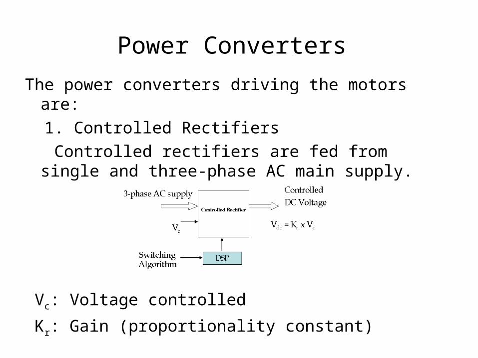
The power converters driving the motors are: 1. Controlled Rectifiers Controlled rectifiers are fed from single
and three-phase AC main supply.
Vc: Voltage controlled
Kr: Gain (proportionality constant)

Power Converters (contd’)
2. Inverters – Voltage and current source converters are fed from a DC link. The DC link is generated with either a controlled or uncontrolled rectifier.
Vc: controlled magnitude command
fc: frequency command
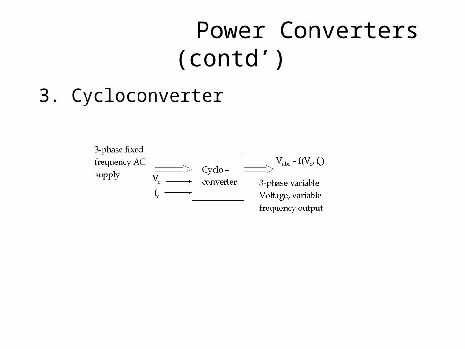
3. Cycloconverter
Power Converters (contd’)

• The controllers implement the control strategy governing the load and motor characteristics
• To match the load and motor, the input to the power converter is controlled (manipulated) by the controller
Controllers
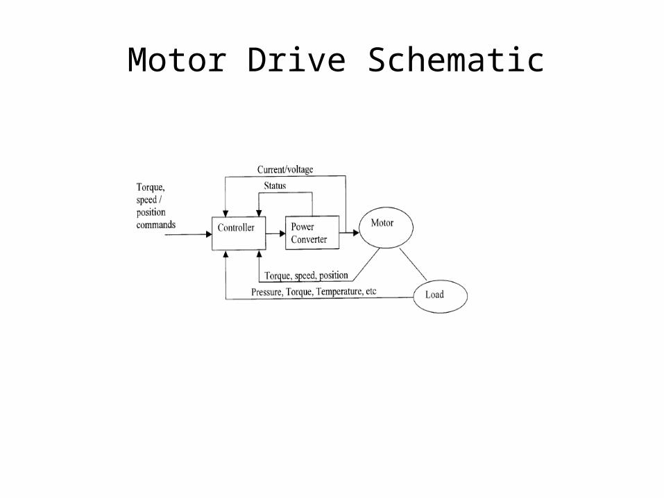
Motor Drive Schematic

Controller Block
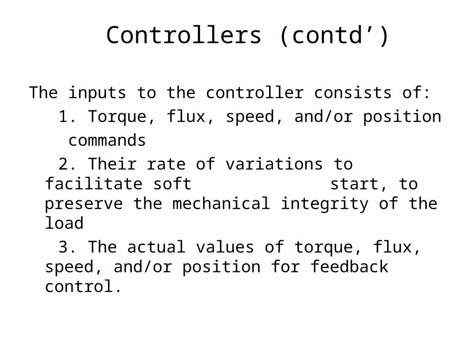
The inputs to the controller consists of: 1. Torque, flux, speed, and/or position commands 2. Their rate of variations to facilitate soft
start, to preserve the mechanical integrity of the load
3. The actual values of torque, flux, speed, and/or position for feedback control.
Controllers (contd’)

4. Limiting values of currents, torque, acceleration, etc.
5. Temperature feedback, instantaneous currents and/or voltages in the motor and/or converter.
Controllers (contd’)

The motor drives a load which has a certain characteristics torque-speed requirement.
In general,
where, k may be an integer of a fraction.
Load
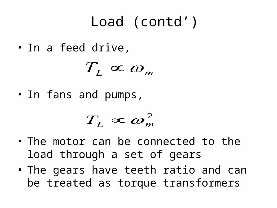
• In a feed drive,
• In fans and pumps,
• The motor can be connected to the load through a set of gears
• The gears have teeth ratio and can be treated as torque transformers
Load (contd’)

• The gears are used to amplify the torque on load side at lower speed compared to the motor speed
• The motors are designed to run at high speeds because it has been found that the higher the speed, the lower is the volume and size of the motor
Load (contd’)

The following laws govern the gear system operation:
1) The power handled by the gear is the same
on both sides
2) Speed on each side is inversely proportional to its tooth number,
Load (contd’)
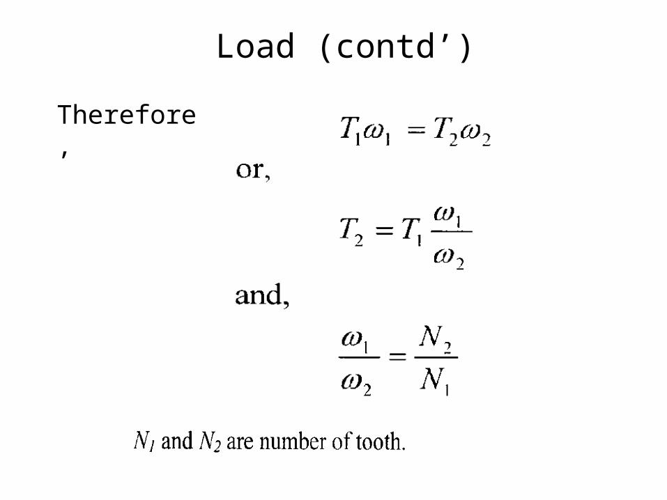
Therefore,
Load (contd’)
Load (contd’)
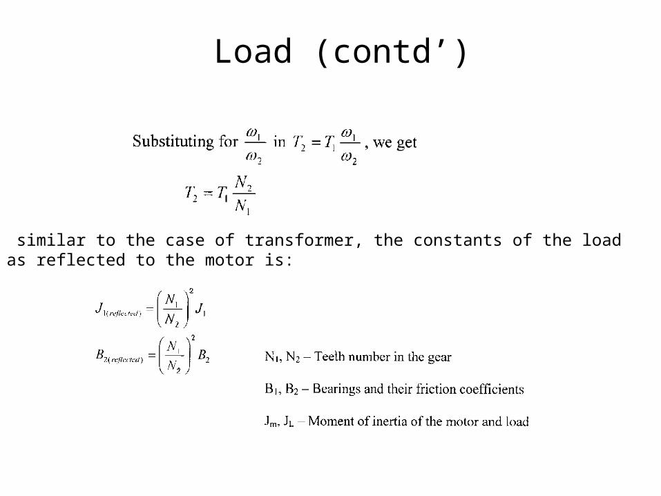
similar to the case of transformer, the constants of the load as reflected to the motor is:
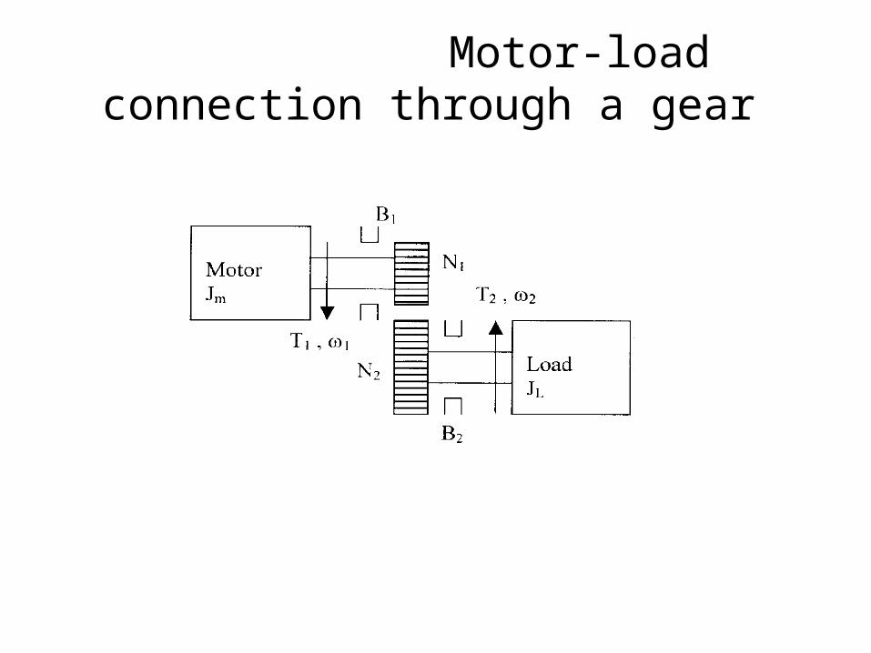
Motor-load connection through a gear
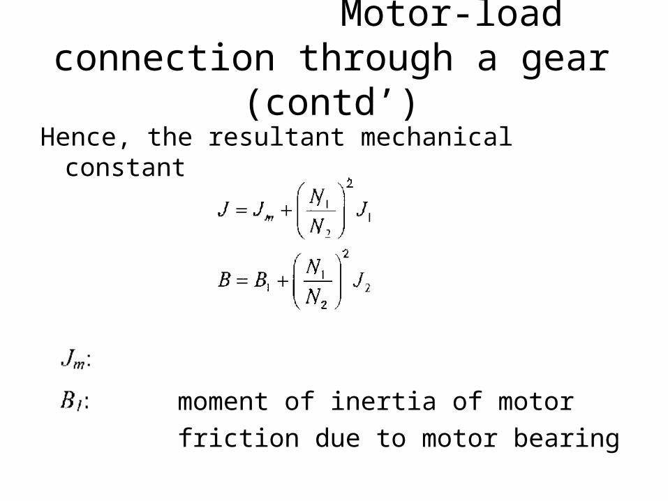
Hence, the resultant mechanical constants are,
moment of inertia of motor friction due to motor bearing
Motor-load connection through a gear (contd’)

moment of inertia of gear system and load
friction due to gear system and load
The torque equation of the motor-load combination is:
Motor-load connection through a gear (contd’)

Control of Electric Machines
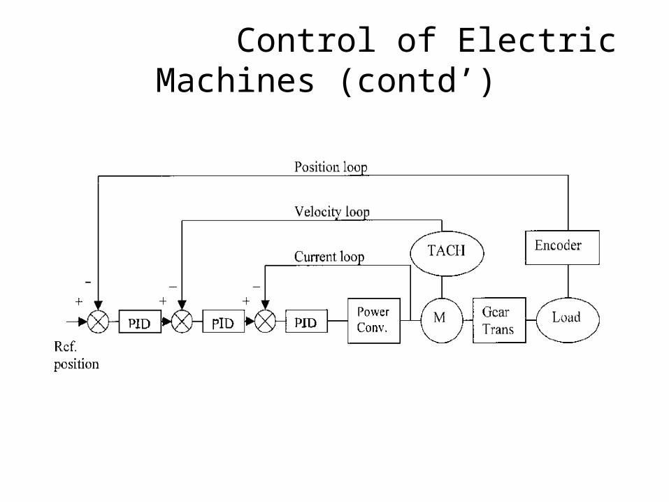
Servo Controllers: offer extremely fast response and precise control of acceleration/ deceleration, speed and torque. Servo Control Systems can accelerate from standstill to 100 RPM in several milliseconds.
Servo Control Systems are designed with three feedback loops:
• Position loop• Velocity loop• Current loop

Elements of Servo Control System are: 1) Motor 2) Power Converter 3) Load and Transmission Systems 4) Encoder (position transducer) 5) Tachometer (speed transducer) 6) Current and Voltage Sensors 7) Potentiometers
Control of Electric Machines (contd’)
Control of Electric Machines (contd’)
The process of selecting an adjustable AC or DC drive is one where load is primary consideration.
When considering load characteristics, the following should be evaluated:
What type of load is associated with the application ?
What is the size of the load?
Load Characteristics
Does the load involve heavy inertia ?
What are the motor considerations ?
Over what speed range are heavy loads encountered ?
Load Characteristics
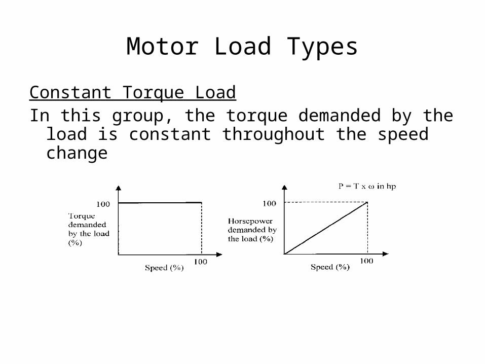
Motor Load Types
Constant Torque LoadIn this group, the torque demanded by the
load is constant throughout the speed change

Motor Load Types (contd’)
The load requires the same amount of torque at low speeds as at high speeds. Loads of this type are essentially friction loads
Torque = lb-ftSpeed = RPM
Examples: Conveyors, Extruders, and Surface Winders

Motor Load Types (contd’)
Constant horsepower Load The horsepower demanded by the load is
constant within the speed range. The load requires high torque at low speeds.
Examples: Center-driven winders and Machine tool
spindles
Motor Load Types (contd’)
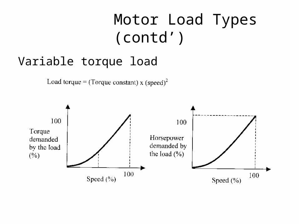
Variable torque load

Load horsepower and torque characteristics
• Constant horsepower, torque varies inversely with speed
• Applications: Metal cutting tools operating over wide speed range, mixer, extruder and special machines where operation at low speed may be continuous
Load horsepower and torque characteristics (contd’)
• Constant torque, horsepower varies as the speed
• Applications: General machinery hoists, conveyors, printing press

Load horsepower and torque characteristics (contd’)
• Horsepower varies as square of the speed, torque varies with speed
• Applications: Positive displacement pumps, some mixers, some extruders

Load horsepower and torque characteristics (contd’)
• Horsepower varies as cube of the speed, torque varies as square of speed
• Applications: All centrifugal pumps and some fans (Note that fan power may vary as the power of speed)
Load horsepower and torque characteristics (contd’)
• High inertial loads
• Applications: Are typically associated with machines using flywheel to supply most of the operating energy, punch press
Load horsepower and torque characteristics (contd’)
• Shock loads
• Applications: Drives of crushers, separators, grinders, conveyors, and vehicular systems
Power converters and motors can be damaged if they are not protected from the overload conditions