Embed Size (px)
Citation preview
motivair
25 John Glenn Drive, #104, Amherst, NY 14228 Phone: (716) 689-0222, FAX: (716) 689-0073
motivair
AIR COOLED CHILLERS
Model: MPCA0005 – MPCA7200
INSTALLATION,
OPERATION, & MAINTENANCE
INSTRUCTIONS
Specializing Water Cooling Systems
Visit our website: www.motivaircorp.com
MOTIVAIR MANUAL for MPC-A CHILLERS LEGAL PROVISIONS, SAFETY INSTRUCTIONS
Operator's Responsibility
This equipment MUST be installed, maintained & operated by a person or persons qualified for this equipment. This chiller contains refrigeration, water circulation, and electrical components. The person most suited for this equipment is a qualified refrigeration technician with a valid refrigeration licence. Intervention by unauthorized or unqualified parties may invalidate the warranty.
WARNING Operation of this system involves potentially Iethal dangers (high voltage and high pressures). Therefore, all safety precautions and warnings described in this manual must be precisely observed. Otherwise, severe or fatal injury may be caused.
SAFETY INSTRUCTIONS The installation, start-up and maintenance of these devices is dangerous, because: • high pressures are generated in the equipment
• electrical parts are energized
• the equipment contains hot pipes
• rotating parts (fans) can cause injury. The devices themselves may be installed in a dangerous position (e.g. roof, etc.) Fans can start without warning.
For these reasons, the equipment must be installed and connected to the electricity/water installations by qualified companies only. Start-up and maintenance must be conducted by a qualified refrigeration company only. Simple maintenance operations on the devices - without opening them - may be performed by the operator. All other work must be performed by specially qualified personnel.

MOTIVAIR MANUAL for MPC-A CHILLERS FONDATIONS, INSTALLATION
Foundation Installation site Installation Structure-transmitted noise Vibration Clearances
All chillers must be mounted on a solid, horizontal surface, suitable for the weight of the chiller. Note the chiller weight is increased by filling with water. Observe all local regulations. Must be dry and protected against freezing. The room temperature must not be colder than 41°F. The system must be installed horizontally. The components are not suitable for exterior installation, without factory modification and approval. Consult Motivair if chiller will be installed outdoors. Compliance with the following basic rules for the installation of chillers with axial fans wiIl ensure problem-free operation and the rated refrigeration capacity. Basic rules: 1. The condenser air is blown out vertically or horizontally. 2. Do not install the chiller close to heat sources. Heated air intake
must be avoided. 3. The condenser fans are rated for ZERO external static pressure.
They do not have the capacity to push air through ducting, which means that NO DUCTS OR MUFFLERS may be used on the inlet or outlet of the chillers.
4. No air short-circuit is permitted, i.e. the heated discharge air from the condenser fans must never be drawn back into the condenser inlet. This will occur if the chiller is too close to a wall, or a low ceiling, or other obstructions.
It is possible that noise or vibration may be transmitted through the ground, or building structure. If this occurs, it may be necessary to install a vibration elimination device. The construction specifications of the customer/engineering contractor regarding structure transmitted noise or vibration must be observed. May be transmitted through the chilled water piping. This can be avoided by the use of flexible piping connections. Must be maintained for servicing and ventilation purposes. All removable side panels must be available for service. A minimum of 3 feet on all sides is required. Consult Motivair for irregular space requirements.
MOTIVAIR MANUAL for MPC-A CHILLERS SITE HANDLING
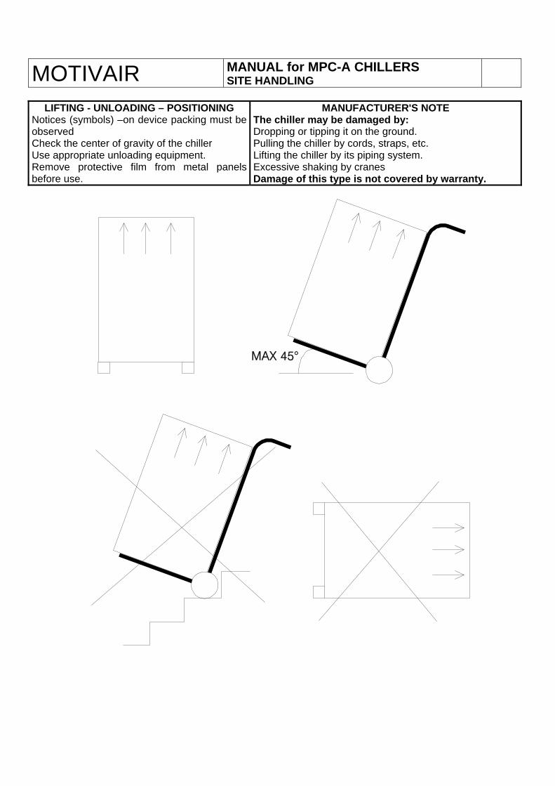
LIFTING - UNLOADING – POSITIONING
Notices (symbols) –on device packing must be observed Check the center of gravity of the chiller Use appropriate unloading equipment. Remove protective film from metal panels before use.
MANUFACTURER'S NOTE The chiller may be damaged by: Dropping or tipping it on the ground. Pulling the chiller by cords, straps, etc. Lifting the chiller by its piping system. Excessive shaking by cranes Damage of this type is not covered by warranty.
MAX 45°


MOTIVAIR MANUAL for MPC-A ELECTRICAL
The manufacturer of the chiller accepts NO LIABILITY
for the installation, or work performed by thecustomer or the installing contractor.
MAIN ELECTRICAL POWER CONNECTION The connection of the chiller to the main electricalpower supply must be carried out by a licensedelectrician, and in strict accordance with LocalSafety Standards and electrical codes.
WIRING DIAGRAM INSPECTION Check that the wiring diagram supplied with thechiller is correct and complete: 1. System designation 2. Order number (see nameplate) 3. Electrical data on wiring diagram - cover sheet
MAX.RUNNING CURRENT FLA
MPCA0005 230V/60Hz/1~/PE 9 Amp MPCA0010 230V/60Hz/1~/PE 11A MPCA0150 460V/60Hz/3~/PE 9A MPCA0200 460V/60Hz/3~/PE 11A MPCA0300 460V/60Hz/3~/PE 15A MPCA0500 460V/60Hz/3~/PE 19A MPCA0800 460V/60Hz/3~/PE 28A MPCA1000 460V/60Hz/3~/PE 33A MPCA1200 460V/60Hz/3~/PE 40A MPCA2200 460V/60Hz/3~/PE 64A MPCA3000 460V/60Hz/3~/PE 76A MPCA3500 460V/60Hz/3∼/PE 92A MPCA4000 460V/60Hz/3~/PE 108A MPCA5000 460V/60Hz/3~/PE 126A MPCA6000 460V/60Hz/3~/PE 148A MPCA7200 460V/60Hz/3~/PE 150A
ELECTRICAL COMPONENTS
Factory-wired electrical panel The control panel mounted in the chiller containsall necessary controls for the chiller . Additional wiring in the panel Additional wiring is permitted but must not modifythe original condition of the factory-installed wiring.All changes must be recorded in the original wiringdiagram and must be available to themanufacturer.
MAIN VOLTAGE SUPPLY
MPC-A 0005 - 0010 230V/1/60 (3 wire) MPC-A 0150- 7200 460V/3/60 (4 wire) The permissible voltage tolerance is ±5%. Thesevalues are BINDING and COMPULSORY.
INFORMATION ON EXTERNAL WIRING Main power feed If for local code or other reasons the cable size of the power supply is larger than the terminal size on the main disconnect switch or power block: 1. A junction box must be fitted to the chiller in
compliance with local codes in order to reducethe cable cross-section, or
2. The main disconnect switch or power block ofthe chiller must be replaced (prior approval ofthe manufacturer is required).
CAUTION – MANUFACTURER’S NOTICE The main disconnect switch in the control panelmust be switched OFF before any site wiring work, Do not switch on the control microprocessor untilcommissioning/start up has been successfullycompleted, or this may invalidate the manufacturer’s warranty.
Model Information: REFER TO DATA ON PLAQUE FOR
EACH MODEL

MOTIVAIR MANUAL for MPC-A WATER CIRCUIT
CCHHIILLLLEEDD WWAATTEERR//GGLLYYCCOOLL 6. Ensure that the water circuit is maintained at
the correct pressure by installing anappropriately sized diaphragm expansiontank close to the inlet of the chiller. Thereturn side of the chiller must be 5-10 psigwhen the pump is running.
7. Install temperature and pressure gauges atthe inlet and outlet of the chiller and the heatload to insure easy inspection andmaintenance
8. All chilled water lines should be insulated.Only insulate pipes AFTER testing the circuitfor leaks.
NOTE: See Water Circuit Appendix A(pages 28-31) for additional informationon how to install & vent a chilled waterpiping system.
G
MANUFACTURER'S SPECIFICATIONS The chiller circuit must be 100% filled with waterfor opperation. If the cooling process causes aloss a water in the circuit, an automatic watermake-up valve must be installed. lnsufficientwater content of the system wiIl lead to
1. Safety devices 2. Controls, due to compressor fluctuations/
hunting (frequent switching) 3. Cooling capacity. If the water content of the complete system is toolow, an additional reservoir may be installed onthe chilled water inlet side of the chiller.
OnIy operate the chiller with the flow switch (supplied), that switches off the chiller in the
event of insufficient water or a faulty pump. If this condition is not satisfied:
ALL WARRANTY CLAIMS SHALL BE INVALID. A flow meter and an automatic water make-up
system can be purchased from the factory.
GLLYYCCOOLL IINN CCIIRRCCUUIITT Glycol mixture The following basic rules must be observed: 1. The freezing point of the mixture must be
lower than the minimum evaporationtemperature, or the lowest outside pipingtemperature, whichever is the lower.
2. See correction factors for glycol concentrationon back page of chiller brochure.
3. Use only an industrial-grade inhibitedethylene glycol or food-grade propyleneglycol solution. DO NOT use auto antifreeze.
4. Check the pH-value of the solution. lt shouldbe about 9 and must never be less than 7.5.
5. Check the pH-value regularly (maintenance).6. DO NOT use galvanized piping or fittings IMPORTANT: NEVER change the antifreezealarm on chiller without written authorization fromfactory. WARRANTY WILL BE VOID
COLD WATER PIPING
Water piping and connection to the chiller mustconform with all generally accepted pipingpractices and local codes. All piping should beperformed by a qualified person or company. The following specifications are intended toprevent damage to the chiller. 1. Avoid unnecessary pressure drop by
ensuring correct pipe sizes and routing. 2. Connect the chiller with vibration eliminators
to avoid transmission of noise or vibration 3. Fit shut-off valves on both sides of the chiller
so that maintenance and repair work can beperformed without draining the piping system.
4. Fit a filter or Y-strainer (40 mesh) to the chillerinlet to protect the evaporator and pump fromforeign particles.
5. IMPORTANT: Filter/strainer must beinstalled, or blockage of theevaporator may occur
6. Fit automatic vents at all local high points ofthe piping system to eliminate air locks. Seechilled water system diagram for location.
WARNING! The glycol/water mixture must not be discharged into the normal water drainage system. lt must be collected in suitable containers and disposed of
in accordance with legal regulations.
MOTIVAIR MANUAL for MPC-A 0005- 0010 FRONT PANEL
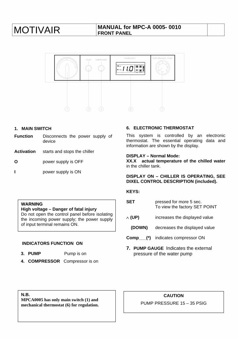
6. ELECTRONIC THERMOSTAT
This system is controlled by an electronicthermostat. The essential operating data and information are shown by the display. DISPLAY – Normal Mode: XX.X actual temperature of the chilled waterin the chiller tank. DISPLAY ON – CHILLER IS OPERATING, SEE DIXEL CONTROL DESCRIPTION (included). KEYS: SET pressed for more 5 sec. To view the factory SET POINT ∧ (UP) increases the displayed value � (DOWN) decreases the displayed value Comp___(*) indicates compressor ON 7. PUMP GAUGE Indicates the external
pressure of the water pump
1. MAIN SWITCH Function Disconnects the power supply of
device Activation starts and stops the chiller
O power supply is OFF I power supply is ON
INDICATORS FUNCTION ON 3. PUMP Pump is on
4. COMPRESSOR Compressor is on
CAUTION PUMP PRESSURE 15 – 35 PSIG
WWAARRNNIINNGG High voltage – Danger of fatal injury Do not open the control panel before isolatingthe incoming power supply; the power supplyof input terminal remains ON.
N.B. MPCA0005 has only main switch (1) and mechanical thermostat (6) for regulation.
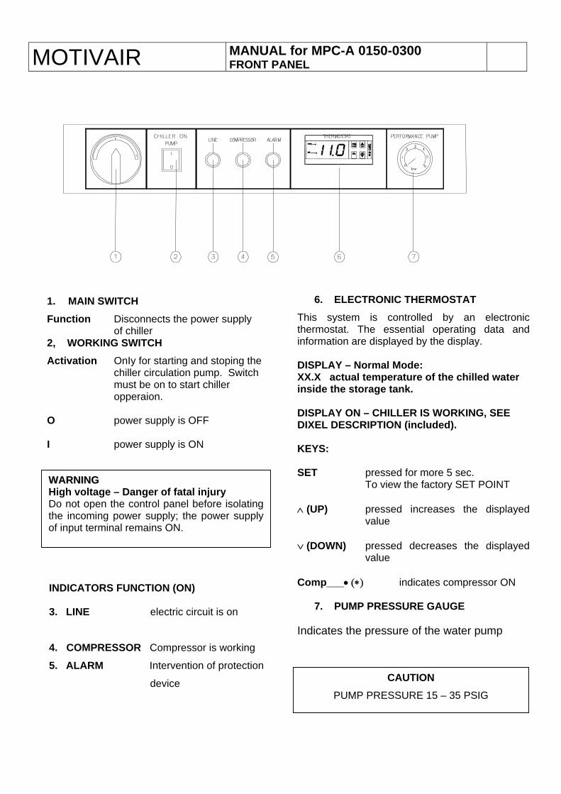
MOTIVAIR MANUAL for MPC-A 0150-0300 FRONT PANEL
6. ELECTRONIC THERMOSTAT
This system is controlled by an electronicthermostat. The essential operating data andinformation are displayed by the display. DISPLAY – Normal Mode: XX.X actual temperature of the chilled water inside the storage tank. DISPLAY ON – CHILLER IS WORKING, SEE DIXEL DESCRIPTION (included). KEYS: SET pressed for more 5 sec. To view the factory SET POINT ∧ (UP) pressed increases the displayed
value ∨ (DOWN) pressed decreases the displayed
value Comp___• (∗) indicates compressor ON
7. PUMP PRESSURE GAUGE Indicates the pressure of the water pump
1. MAIN SWITCH Function Disconnects the power supply
of chiller 2, WORKING SWITCH Activation OnIy for starting and stoping the
chiller circulation pump. Switch must be on to start chiller opperaion.
O power supply is OFF I power supply is ON
INDICATORS FUNCTION (ON) 3. LINE electric circuit is on
4. COMPRESSOR Compressor is working
5. ALARM Intervention of protection
device CAUTION PUMP PRESSURE 15 – 35 PSIG
WWAARRNNIINNGG High voltage – Danger of fatal injury Do not open the control panel before isolatingthe incoming power supply; the power supplyof input terminal remains ON.
MOTIVAIR MANUAL for MPC-A 0005 - 0300
DIXEL CONROLS
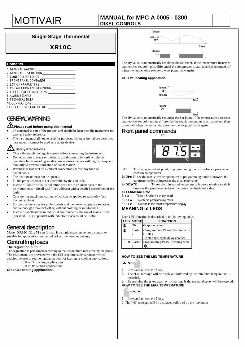
Single Stage Thermostat
XR10C
Contents 1. GENERAL WARNING _________________________
The Hy value is automatically set above the Set Point. If the temperature increases and reaches set point plus differential the compressor is started and then turned off when the temperature reaches the set point value again. CH = ht: heating application.
2. GENERAL DESCRIPTION______________________ 3. CONTROLLING LOADS _______________________ 4. FRONT PANEL COMMANDS ___________________ 5. LIST OF PARAMETERS _______________________ 6. INSTALLATION AND MOUNTING________________ 7. ELECTRICAL CONNECTIONS __________________ 8. ALARM SIGNALS ____________________________ 9. TECHNICAL DATA ___________________________ 10. CONNECTIONS_____________________________ 11. DEFAULT SETTING VALUES __________________ G
The Hy value is automatically set under the Set Point. If the temperature decreases and reaches set point minus differential the regulation output is activated and then turned off when the temperature reaches the set point value again.
F
GEENNEERRAALL WWAARRNNIINNGG Please read before using this manual
• This manual is part of the product and should be kept near the instrument for easy and quick reference.
• The instrument shall not be used for purposes different from those described hereunder. It cannot be used as a safety device.
Frroonntt ppaanneell ccoommmmaannddss
Safety Precautions • Check the supply voltage is correct before connecting the instrument. • Do not expose to water or moisture: use the controller only within the
operating limits avoiding sudden temperature changes with high atmospheric humidity to prevent formation of condensation
• Warning: disconnect all electrical connections before any kind of maintenance.
• The instrument must not be opened. • Fit the probe where it is not accessible by the end user. • In case of failure or faulty operation send the instrument back to the
distributor or to “Dixell s.r.l.” (see address) with a detailed description of the fault.
• Consider the maximum current which can be applied to each relay (see Technical Data).
• Ensure that the wires for probes, loads and the power supply are separated and far enough from each other, without crossing or intertwining.
• In case of applications in industrial environments, the use of mains filters (our mod. FT1) in parallel with inductive loads could be useful.
G
SET: To display target set point, In programming mode it selects a parameter or
confirm an operation. è (UP): To see the max stored temperature; in programming mode it browses the
parameter codes or increases the displayed value. à (DOWN) To see the min stored temperature; in programming mode it
browses the parameter codes or increases the displayed value. KEY COMBINATIONS: è + à To lock & unlock the keyboard. SET + à To enter in programming mode. SET + è To return to the room temperature display. MEANING of LEDS Each LED function is described in the following table.
Geenneerraall ddeessccrriippttiioonn Model XR10C, 32 x 74 mm format, is a single stage temperature controller suitable for applications in the field of refrigeration or heating.
CCoonnttrroolllliinngg llooaaddss The regulation output The regulation is performed according to the temperature measured by the probe. The instruments are provided with the CH programmable parameter which enables the user to set the regulation both for heating or cooling applications: · CH = CL: cooling applications · CH = Ht: heating applications CH = CL: cooling applications.
LED MODE FUNCTION ON Output enabled
Flashing
-Programming Phase (flashing with LED1) - Anti-short cycle delay enabled
LED1 Flashing
Programming Phase (flashing with )
HOW TO SEE THE MIN TEMPERATURE
1. Press and release the à key. 2. The “Lo” message will be displayed followed by the minimum temperature
recorded. 3. By pressing the à key again or by waiting 5s the normal display will be restored. HOW TO SEE THE MAX TEMPERATURE
1. Press and release the è key. 2. The “Hi” message will be displayed followed by the maximum
MOTIVAIR MANUAL for MPC-A 0005 - 0300 DIXEL CONTROLS
temperature recorded. 3. By pressing the è key again or by waiting 5s the normal display
will be restored. HOW TO RESET THE max OR min TEMPERATURE RECORDED 1. Hold press the SET key for more than 3s, while the max. or min
temperature is displayed. (rSt message will be displayed) 2. To confirm the operation the “rSt” message starts blinking and the normal
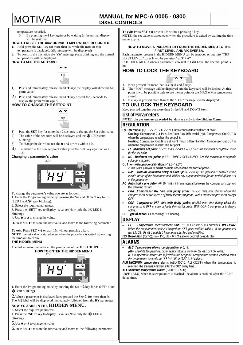
temperature will be displayed. HOW TO SEE THE SETPOINT
1) Push and immediately release the SET key: the display will show the Set
point value; 2) Push and immediately release the SET key or wait for 5 seconds to
display the probe value again. HOW TO CHANGE THE SETPOINT
1) Push the SET key for more than 2 seconds to change the Set point value;2) The value of the set point will be displayed and the LED starts
blinking; 3) To change the Set value use the è or à arrows within 10s. 4) To memorise the new set point value push the SET key again or wait
10s. Changing a parameter’s value
To change the parameter’s value operate as follows: 1. Enter the Programming mode by pressing the Set and DOWN key for 3s (LED 1 and start blinking). 2. Select the required parameter. 3. Press the “SET” key to display its value (Now only the LED is blinking). 4. Use è or à to change its value. 5.Press “SET” to store the new value and move to the following parameter. To exit: Press SET + è or wait 15s without pressing a key. NOTE: the set value is stored even when the procedure is exited by waiting the time-out to expire. THE HIDDEN MENU The hidden menu Includes all the parameters of the instrument.
HOW TO ENTER THE HIDDEN MENU
1. Enter the Programming mode by pressing the Set + à key for 3s (LED 1 and
start blinking).
2.When a parameter is displayed keep pressed the Set+à for more than 7s. The Pr2 label will be displayed immediately followed from the HY parameter.
NOW YOU ARE IN THE HIDDEN MENU. 3. Select the required parameter. 4. Press the “SET” key to display its value (Now only the LED is blinking). 5.Use è or à to change its value. 6.Press “SET” to store the new value and move to the following parameter.
To exit: Press SET + è or wait 15s without pressing a key. NOTE: the set value is stored even when the procedure is exited by waiting the time-out to expire.
HOW TO MOVE A PARAMETER FROM THE HIDDEN MENU TO THE FIRST LEVEL AND VICEVERSA.
Each parameter present in the HIDDEN MENU can be removed or put into “THE FIRST LEVEL” (user level) by pressing “SET + à”. In HIDDEN MENU when a parameter is present in Fisrt Level the decimal point is on. HOW TO LOCK THE KEYBOARD
1. Keep pressed for more than 3 s the è and à keys. 2. The “POF” message will be displayed and the keyboard will be locked. At this
point it will be possible only to see the set point or the MAX o Min temperature stored
3. If a key is pressed more than 3s the “POF” message will be displayed. TO UNLOCK THE KEYBOARD Keep pressed together for more than 3s the UP and DOWN keys.
LLiisstt ooff PPaarraammeetteerrss NOTE: the parameters preceded by dots are only in the Hidden Menu.
REGULATION Hy Differential: (0,1 ÷ 25,5°C / 1÷255 °F) Intervention differential for set point.
Cooling: Compressor Cut IN is Set Point Plus Differential (Hy). Compressor Cut OUT is when the temperature reaches the set point. Heating: Compressor Cut IN is Set Point minus Differential (Hy). Compressor Cut OUT is when the temperature reaches the set point.
• LS Minimum set point: (- 50°C÷SET / -58°F÷SET): Sets the minimum acceptable value for the set point.
• US Maximum set point: (SET÷ 150°C / SET÷302°F). Set the maximum acceptable value for set point.
Ot Thermostat probe calibration: (-12.0÷12.0°C; -120÷120°F) allows to adjust possible offset of the thermostat probe.
• OdS Outputs activation delay at start up: (0÷255min) This function is enabled at the initial start up of the instrument and inhibits any output activation for the period of time set in the parameter.
AC Anti-short cycle delay: (0÷50 min) minimum interval between the compressor stop and the following restart.
• COn Compressor ON time with faulty probe: (0÷255 min) time during which the compressor is active in case of faulty thermostat probe. With COn=0 compressor is always OFF.
• COF Compressor OFF time with faulty probe: (0÷255 min) time during which the compressor is OFF in case of faulty thermostat probe. With COF=0 compressor is always active.
CH Type of action: CL = cooling; Ht = heating.
DISPLAY • CF Temperature measurement unit: °C = Celsius; °F= Fahrenheit. WARNING:
When the measurement unit is changed the SET point and the values of the parameters Hy, LS, US, Ot, ALU and ALL have to be checked and modified)
rES Resolution (for °C): (in = 1°C; dE = 0.1 °C) allows decimal point display.
ALARMS • ALC Temperature alarms configuration: (Ab; rE) (Ab= absolute temperature: alarm temperature is given by the ALL or ALU values.
rE = temperature alarms are referred to the set point. Temperature alarm is enabled when the temperature exceeds the “SET+ALU” or “SET-ALL” values.
ALU MAXIMUM temperature alarm: (ALL÷150°C; ALL÷302°F) when this temperature is reached the alarm is enabled, after the “Ald” delay time.
ALL Minimum temperature alarm: (-50.0 °C ÷ ALU; -58°F ÷ALU) when this temperature is reached the alarm is enabled, after the “Ald” delay time.
MOTIVAIR MANUAL for MPC-A 0005 - 0300 DIXEL CONTROLS
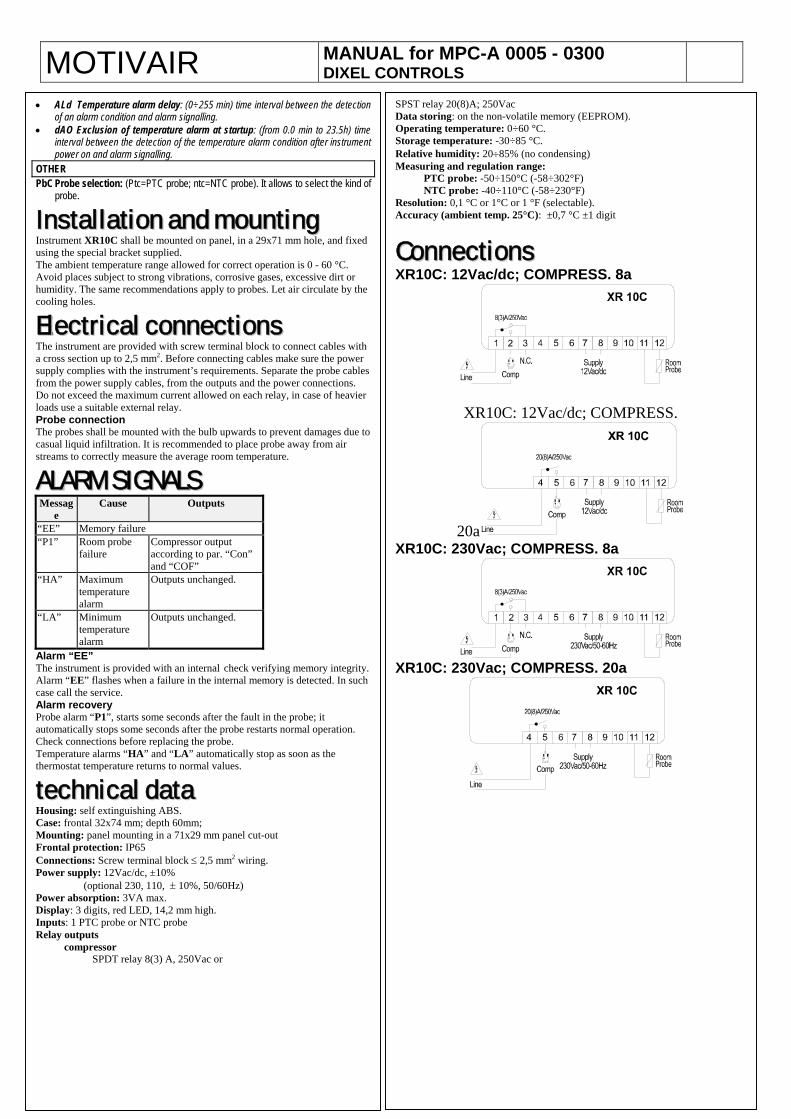
• ALd Temperature alarm delay: (0÷255 min) time interval between the detection of an alarm condition and alarm signalling.
• dAO Exclusion of temperature alarm at startup: (from 0.0 min to 23.5h) time interval between the detection of the temperature alarm condition after instrument power on and alarm signalling.
OTHER PbC Probe selection: (Ptc=PTC probe; ntc=NTC probe). It allows to select the kind of
probe.
IInnssttaallllaattiioonn aanndd mmoouunnttiinngg Instrument XR10C shall be mounted on panel, in a 29x71 mm hole, and fixed using the special bracket supplied. The ambient temperature range allowed for correct operation is 0 - 60 °C. Avoid places subject to strong vibrations, corrosive gases, excessive dirt or humidity. The same recommendations apply to probes. Let air circulate by the cooling holes.
EElleeccttrriiccaall ccoonnnneeccttiioonnss The instrument are provided with screw terminal block to connect cables with a cross section up to 2,5 mm2. Before connecting cables make sure the power supply complies with the instrument’s requirements. Separate the probe cables from the power supply cables, from the outputs and the power connections. Do not exceed the maximum current allowed on each relay, in case of heavier loads use a suitable external relay. Probe connection The probes shall be mounted with the bulb upwards to prevent damages due to casual liquid infiltration. It is recommended to place probe away from air streams to correctly measure the average room temperature.
AALLAARRMM SSIIGGNNAALLSS Messag
e Cause Outputs
“EE” Memory failure “P1”
Room probe failure
Compressor output according to par. “Con” and “COF”
“HA”
Maximum temperature alarm
Outputs unchanged.
“LA” Minimum temperature alarm
Outputs unchanged.
Alarm “EE” The instrument is provided with an internal check verifying memory integrity. Alarm “EE” flashes when a failure in the internal memory is detected. In such case call the service. Alarm recovery Probe alarm “P1”, starts some seconds after the fault in the probe; it automatically stops some seconds after the probe restarts normal operation. Check connections before replacing the probe. Temperature alarms “HA” and “LA” automatically stop as soon as the thermostat temperature returns to normal values.
tteecchhnniiccaall ddaattaa Housing: self extinguishing ABS. Case: frontal 32x74 mm; depth 60mm; Mounting: panel mounting in a 71x29 mm panel cut-out Frontal protection: IP65 Connections: Screw terminal block ≤ 2,5 mm2 wiring. Power supply: 12Vac/dc, ±10% (optional 230, 110, ± 10%, 50/60Hz) Power absorption: 3VA max. Display: 3 digits, red LED, 14,2 mm high. Inputs: 1 PTC probe or NTC probe Relay outputs compressor SPDT relay 8(3) A, 250Vac or
SPST relay 20(8)A; 250VacData storing: on the non-volatile memory (EEPROM). Operating temperature: 0÷60 °C. Storage temperature: -30÷85 °C. Relative humidity: 20÷85% (no condensing) Measuring and regulation range:
PTC probe: -50÷150°C (-58÷302°F) NTC probe: -40÷110°C (-58÷230°F)
Resolution: 0,1 °C or 1°C or 1 °F (selectable). Accuracy (ambient temp. 25°C): ±0,7 °C ±1 digit
CCoonnnneeccttiioonnss XR10C: 12Vac/dc; COMPRESS. 8a
XR10C: 12Vac/dc; COMPRESS.
20a XR10C: 230Vac; COMPRESS. 8a
XR10C: 230Vac; COMPRESS. 20a
MOTIVAIR MANUAL for MPC-A 0005 - 0300 DIXEL CONTROLS
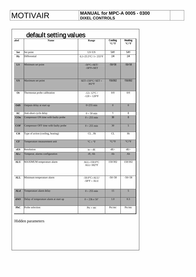
ddeeffaauulltt sseettttiinngg vvaalluueess Label Name Range Cooling
°C/°F Heating °C/°F
Set Set point LS÷US 5/41 5/41 Hy Differential 0,1÷25.5°C/ 1÷ 255°F 2/4 2/4
LS Minimum set point -50°C÷SET/ -58°F÷SET
-50/-58 -50/-58
US Maximum set point SET÷150°C/ SET ÷ 302°F
150/302 150/302
Ot Thermostat probe calibration -12÷ 12°C / -120 ÷ 120°F
0/0 0/0
OdS Outputs delay at start up 0÷255 min 0 0
AC Anti-short cycle delay 0 ÷ 50 min 1 0 COn Compressor ON time with faulty probe 0 ÷ 255 min 30 0
COF Compressor OFF time with faulty probe 0 ÷ 255 min 30 5
CH Type of action (cooling, heating) CL , Ht CL Ht
CF Temperature measurement unit °C ÷ °F °C/°F °C/°F
rES Resolution in ÷ dE dE/- dE/-
ALc Temperat. alarms configuration rE; Ab Ab Ab
ALU MAXIMUM temperature alarm ALL÷150.0°C ALL÷302°F
150/302 150/302
ALL Minimum temperature alarm -50.0°C÷ALU/ -58°F ÷ ALU
-50/-58 -50/-58
ALd Temperature alarm delay 0 ÷ 255 min 15 5
dAO Delay of temperature alarm at start up 0 ÷ 23h e 50’ 1.0 0.3
PbC Probe selection Ptc ÷ ntc Ptc/ntc Ptc/ntc
Hidden parameters
MOTIVAIR MANUAL for MPC-A 0500 - 7200 FRONT PANEL
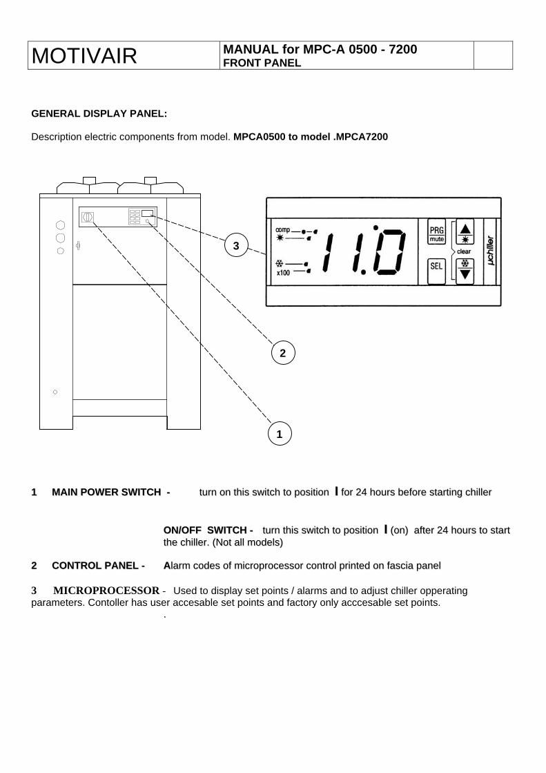
GENERAL DISPLAY PANEL: Description electric components from model. MPCA0500 to model .MPCA7200
1
3
2
11 MMAAIINN PPOOWWEERR SSWWIITTCCHH -- ttuurrnn oonn tthhiiss sswwiittcchh ttoo ppoossiittiioonn II ffoorr 2244 hhoouurrss bbeeffoorree ssttaarrttiinngg cchhiilllleerr
OONN//OOFFFF SSWWIITTCCHH -- ttuurrnn tthhiiss sswwiittcchh ttoo ppoossiittiioonn II ((oonn)) aafftteerr 2244 hhoouurrss ttoo ssttaarrtt tthhee cchhiilllleerr.. ((NNoott aallll mmooddeellss))
22 CCOONNTTRROOLL PPAANNEELL -- AAllaarrmm ccooddeess ooff mmiiccrroopprroocceessssoorr ccoonnttrrooll pprriinntteedd oonn ffaasscciiaa ppaanneell 3 MICROPROCESSOR - Used to display set points / alarms and to adjust chiller opperating parameters. Contoller has user accesable set points and factory only acccesable set points. ..
7
I
I
J
L K
J
ABCDE
FG
H
FG
H
L
KABCDE
EN
GL
ISH
µC2 - +030220731 - rel. 1.0 - 27.07.2006
1. INTRODUCTION
1.1 General description The µC2 is a new compact CAREL electronic controller, the same size as a normal thermostat, for the complete management of chillers and heat pumps: it can control air-air, air-water, water-water and condensing units.
1.1.1 Main functions control of the water inlet and evaporator outlet temperature;defrost management by time and/or by temperature or pressure;fan speed control;complete alarm management;connection to serial line for supervision/telemaintenance;elimination of the expansion vessel.
- Driver function Management of electronic expansion valves.
1.1.2 Controlled devices compressor;condenser fans;reversing valve;water pumps for evaporator and/or condenser, and outlet fan (air-air);antifreeze heater;alarm signal device.
1.1.3 Programming CAREL offers the possibility to confi gure all the unit parameters not only from the keypad on the front panel, but also using:
a hardware key;a serial line.
1.2 User interface
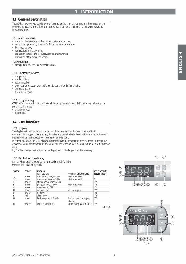
1.2.1 Display The display features 3 digits, with the display of the decimal point between -99.9 and 99.9. Outside of this range of measurement, the value is automatically displayed without the decimal (even if internally the unit still operates considering the decimal part).In normal operation, the value displayed corresponds to the temperature read by probe B1, that is, the evaporator water inlet temperature (for water chillers) or the ambient air temperature for direct expansion units.Fig. 1.a show the symbols present on the display and on the keypad and their meanings.
1.2.2 Symbols on the display Display with 3 green digits (plus sign and decimal point), ambersymbols and red alarm symbols.
symbol colour meaning reference refri-gerant circuit with LED ON con LED lampeggiante
1; 2 amber compressor 1 and/or 2 ON start up request 11; 3 amber compressor 3 and/or 3 ON start up request 2A amber at least one compressor ON 1/2B amber pump/air outlet fan ON start up request 1/2C amber condenser fan ON 1/2D amber defrost active defrost request 1/2E amber heater ON 1/2F red alarm active 1/2G amber heat pump mode (P6=0) heat pump mode request
(P6=0)1/2
H amber chiller mode (P6=0) chiller mode request (P6=0) 1/2Table 1.a
••••••
•
••••••
••
Fig. 1.a
8
EN
GL
ISH
µC2 - +030220731 - rel. 1.0 - 27.07.2006
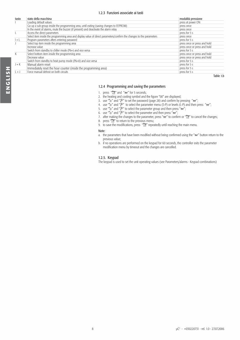
1.2.3 Funzioni associate ai tastitasto stato della macchina modalità pressioneI Loading default values press at power ON
Go up a sub-group inside the programming area, until exiting (saving changes to EEPROM) press once In the event of alarms, mute the buzzer (if present) and deactivate the alarm relay press once
L Access the direct parameters press for 5 s Select item inside the programming area and display value of direct parameters/confi rm the changes to the parameters press once
I + L Program parameters afters entering password press for 5 sJ Select top item inside the programming area press once or press and hold
Increase value press once or press and hold Switch from standby to chiller mode (P6=) and vice versa press for 5 s
K Select bottom item inside the programming area press once or press and hold Decrease value press once or press and hold Switch from standby to heat pump mode (P6=0) and vice versa press for 5 s
J + K Manual alarm reset press for 5 s Immediately reset the hour counter (inside the programming area) press for 5 s
L + J Force manual defrost on both circuits press for 5 sTable 1.b
1.2.4 Programming and saving the parameters
press “ “ and “ ” for 5 seconds; the heating and cooling symbol and the fi gure “00” are displayed;use “ ” and “ ” to set the password (page 28) and confi rm by pressing “ ”;use “ ” and “ ” to select the parameter menu (S-P) or levels (L-P) and then press “ ”;use “ ” and “ ” to select the parameter group and then press “ ”;use “ ” and “ “ to select the parameter and then press “ ”; after making the changes to the parameter, press “ ” to confi rm or “ ” to cancel the changes;press “ ” to return to the previous menu; to save the modifi cations, press “ ” repeatedly until reaching the main menu.
Note: the parameters that have been modifi ed without being confi rmed using the “ ” button return to the previous value; if no operations are performed on the keypad for 60 seconds, the controller exits the parameter modifi cation menu by timeout and the changes are cancelled.
1.2.5. Keypad The keypad is used to set the unit operating values (see Parameters/alarms - Keypad combinations)
1.2.3.4.5.6.7.8.9.
a.
b.
9
EV driver
EV driver EV driverDIN
EN
GL
ISH
µC2 - +030220731 - rel. 1.0 - 27.07.2006
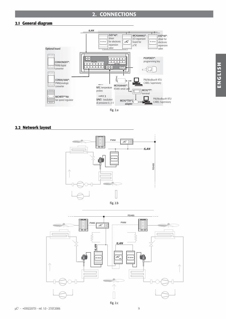
2. CONNECTIONS
2.1 General diagram
Fig. 2.a
2.2 Network layout
Fig. 2.b
Fig. 2.c
EVD*40*: driver for electronic expansion valve
MCH200002*: I/O expansion board for µ2SE
EVD*40*: driver for electronic expansion valveOptional board
CONVONOFF*: PWM/digital converter
CONV0/10A0*: PWM/analogic converter
MCH2*T*: terminal
PW/Modbus® RTU CAREL Supervisory
NTC: temperature probes
MCH200485*: RS485 serial card
PSOPZKEY*: programming key
PW/Modbus® RTU CAREL Supervisory
SPKT: trasduttori di pressione 0...5 V
MCHRTF**A0: fan speed regulator MCH2*TSV*:
adapter
25
For 5�
And For 5�Sa ve in the EEPROM
OrOr
Or
EN
GL
ISH
µC2 - +030220731 - rel. 1.0 - 27.07.2006
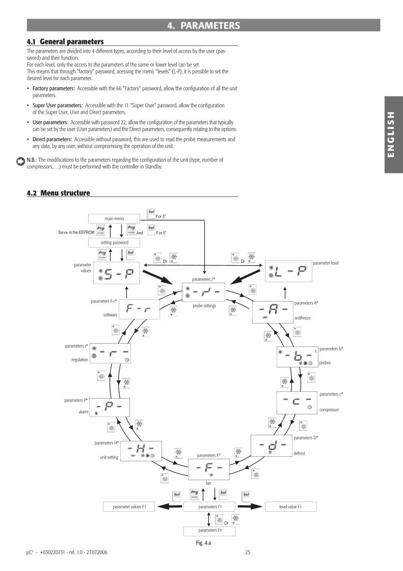
4.1 General parameters The parameters are divided into 4 different types, according to their level of access by the user (pas-sword) and their function.For each level, only the access to the parameters of the same or lower level can be set.This means that through “factory” password, acessing the menù “levels” (L-P), it is possible to set the desired level for each parameter.
Factory parameters: Accessible with the 66 “Factory” password, allow the confi guration of all the unit parameters.
Super User parameters: Accessible with the 11 “Super User” password, allow the confi guration of the Super User, User and Direct parameters.
User parameters: Accessible with password 22, allow the confi guration of the parameters that typically can be set by the user (User parameters) and the Direct parameters, consequently relating to the options.
Direct parameters: Accessible without password, this are used to read the probe measurements and any data, by any user, without compromising the operation of the unit.
N.B.: The modifi cations to the parameters regarding the confi guration of the unit (type, number of compressors,…) must be performed with the controller in Standby.
4.2 Menu structure
•
•
•
•
4. PARAMETERS
main menù
setting password
parameter values
parameter level
parameters A*parameters F-r*
parameters r*parameters b*
regulationprobes
antifreezesoftware
parameters P*
alarm
parameters H*
unit setting parameters F*
fan
parameters D*
defrost
parameters c*
compressor
parameters /*
probe settings
parameter values F1 parameters F1 level value F1
parameters Fn
Fig. 4.a
26
EN
GL
ISH
µC2 - +030220731 - rel. 1.0 - 27.07.2006
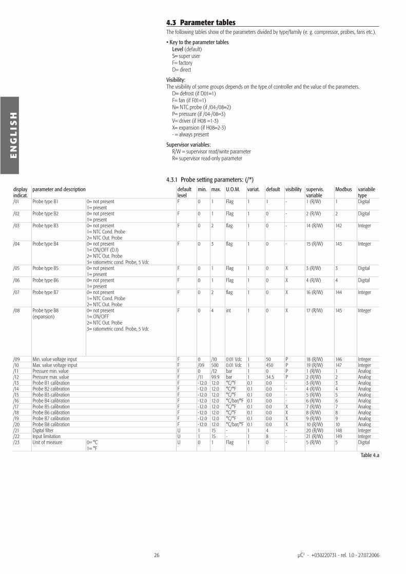
4.3 Parameter tables The following tables show of the parameters divided by type/family (e. g. compressor, probes, fans etc.).
• Key to the parameter tablesLevel (default)S= super userF= factoryD= direct
Visibility: The visibility of some groups depends on the type of controller and the value of the parameters.
D= defrost (if D01=1)F= fan (if F01=1)N= NTC probe (if /04-/08=2)P= pressure (if /04-/08=3)V= driver (if H08 =1-3)X= expansion (if H08=2-3)- = always present
Supervisor variables:R/W = supervisor read/write parameterR= supervisor read-only parameter
4.3.1 Probe setting parameters: (/*)display indicat.
parameter and description default level
min. max. U.O.M. variat. default visibility supervis. variable
Modbus variabile type
/01 Probe type B1 0= not present 1= present
F 0 1 Flag 1 1 - 1 (R/W) 1 Digital
/02 Probe type B2 0= not present 1= present
F 0 1 Flag 1 0 - 2 (R/W) 2 Digital
/03 Probe type B3 0= not present 1= NTC Cond. Probe 2= NTC Out. Probe
F 0 2 fl ag 1 0 - 14 (R/W) 142 Integer
/04 Probe type B4 0= not present 1= ON/OFF (D.I) 2= NTC Out. Probe 3= ratiometric cond. Probe, 5 Vdc
F 0 3 fl ag 1 0 - 15 (R/W) 143 Integer
/05 Probe type B5 0= not present 1= present
F 0 1 Flag 1 0 X 3 (R/W) 3 Digital
/06 Probe type B6 0= not present 1= present
F 0 1 Flag 1 0 X 4 (R/W) 4 Digital
/07 Probe type B7 0= not present 1= NTC Cond. Probe 2= NTC Out. Probe
F 0 2 fl ag 1 0 X 16 (R/W) 144 Integer
/08 Probe type B8 (expansion)
0= not present 1= ON/OFF 2= NTC Out. Probe 3= ratiometric cond. Probe, 5 Vdc
F 0 4 int 1 0 X 17 (R/W) 145 Integer
/09 Min. value voltage input F 0 /10 0.01 Vdc 1 50 P 18 (R/W) 146 Integer/10 Max. value voltage input F /09 500 0.01 Vdc 1 450 P 19 (R/W) 147 Integer/11 Pressure min. value F 0 /12 bar 1 0 P 1 (R/W) 1 Analog/12 Pressure max. value F /11 99.9 bar 1 34.5 P 2 (R/W) 2 Analog/13 Probe B1 calibration F -12.0 12.0 °C/°F 0.1 0.0 - 3 (R/W) 3 Analog/14 Probe B2 calibration F -12.0 12.0 °C/°F 0.1 0.0 - 4 (R/W) 4 Analog/15 Probe B3 calibration F -12.0 12.0 °C/°F 0.1 0.0 - 5 (R/W) 5 Analog/16 Probe B4 calibration F -12.0 12.0 °C/bar/°F 0.1 0.0 - 6 (R/W) 6 Analog/17 Probe B5 calibration F -12.0 12.0 °C/°F 0.1 0.0 X 7 (R/W) 7 Analog/18 Probe B6 calibration F -12.0 12.0 °C/°F 0.1 0.0 X 8 (R/W) 8 Analog/19 Probe B7 calibration F -12.0 12.0 °C/°F 0.1 0.0 X 9 (R/W) 9 Analog/20 Probe B8 calibration F -12.0 12.0 °C/bar/°F 0.1 0.0 X 10 (R/W) 10 Analog/21 Digital fi lter U 1 15 - 1 4 - 20 (R/W) 148 Integer/22 Input limitation U 1 15 - 1 8 - 21 (R/W) 149 Integer/23 Unit of measure 0= °C
1= °FU 0 1 Flag 1 0 - 5 (R/W) 5 Digital
Table 4.a
27
EN
GL
ISH
µC2 - +030220731 - rel. 1.0 - 27.07.2006
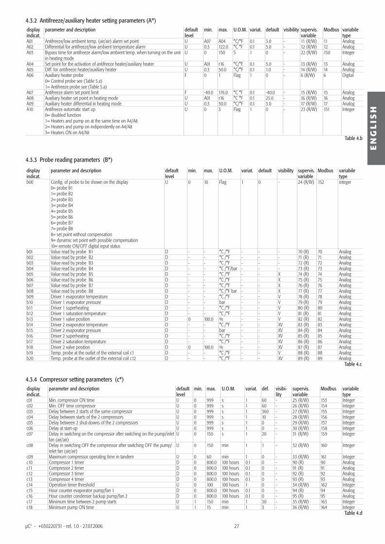
4.3.2 Antifreeze/auxiliary heater setting parameters (A*)display indicat.
parameter and description default level
min. max. U.O.M. variat. default visibility supervis. variable
Modbus variabile type
A01 Antifreeze/low ambient temp. (air/air) alarm set point U A07 A04 °C/°F 0.1 3.0 - 11 (R/W) 11 AnalogA02 Differential for antifreeze/low ambient temperature alarm U 0.3 122.0 °C °F 0.1 5.0 - 12 (R/W) 12 AnalogA03 Bypass time for antifreeze alarm/low ambient temp. when turning on the unit
in heating modeU 0 150 S 1 0 - 22 (R/W) 150 Integer
A04 Set point for the activation of antifreeze heater/auxiliary heater U A01 r16 °C/°F 0.1 5.0 - 13 (R/W) 13 AnalogA05 Diff. for antifreeze heater/auxiliary heater U 0.3 50.0 °C/°F 0.1 1.0 - 14 (R/W) 14 AnalogA06 Auxiliary heater probe
0= Control probe see (Table 5.a)1= Antifreeze probe see (Table 5.a)
F 0 1 Flag 1 0 - 6 (R/W) 6 Digital
A07 Antifreeze alarm set point limit F -40.0 176.0 °C °F 0.1 -40.0 - 15 (R/W) 15 AnalogA08 Auxiliary heater set point in heating mode U A01 r16 °C °F 0.1 25.0 - 16 (R/W) 16 AnalogA09 Auxiliary heater differential in heating mode U 0.3 50.0 °C/°F 0.1 3.0 - 17 (R/W) 17 AnalogA10 Antifreeze automatic start up
0= disabled function1= Heaters and pump on at the same time on A4/A82= Heaters and pump on indipendently on A4/A83= Heaters ON on A4/A8
U 0 3 Flag 1 0 - 23 (R/W) 151 Integer
Table 4.b
4.3.3 Probe reading parameters (B*)
display indicat.
parameter and description default level
min. max. U.O.M. variat. default visibility supervis. variable
Modbus variabile type
b00 Confi g. of probe to be shown on the display0= probe B11= probe B22= probe B33= probe B44= probe B55= probe B66= probe B77= probe B88= set point without compensation9= dynamic set point with possible compensation10= remote ON/OFF digital input status
U 0 10 Flag 1 0 - 24 (R/W) 152 integer
b01 Value read by probe B1 D - - °C /°F - - - 70 (R) 70 Analogb02 Value read by probe B2 D - - °C /°F - - - 71 (R) 71 Analogb03 Value read by probe B3 D - - °C /°F - - - 72 (R) 72 Analogb04 Value read by probe B4 D - - °C /°F/bar - - - 73 (R) 73 Analogb05 Value read by probe B5 D - - °C /°F - - X 74 (R) 74 Analogb06 Value read by probe B6 D - - °C /°F - - X 75 (R) 75 Analogb07 Value read by probe B7 D - - °C /°F - - X 76 (R) 76 Analogb08 Value read by probe B8 D - - °C /°F bar - - X 77 (R) 77 Analogb09 Driver 1 evaporator temperature D - - °C /°F - - V 78 (R) 78 Analogb10 Driver 1 evaporator pressure D - - bar - - V 79 (R) 79 Analogb11 Driver 1 superheating D - - °C /°F - - V 80 (R) 80 Analogb12 Driver 1 saturation temperature D - - °C /°F - - V 81 (R) 81 Analogb13 Driver 1 valve position D 0 100.0 % - - V 82 (R) 82 Analogb14 Driver 2 evaporator temperature D - - °C /°F - - XV 83 (R) 83 Analogb15 Driver 2 evaporator pressure D - - bar - - XV 84 (R) 84 Analogb16 Driver 2 superheating D - - °C /°F - - XV 85 (R) 85 Analogb17 Driver 2 saturation temperature D - - °C /°F - - XV 86 (R) 86 Analogb18 Driver 2 valve position D 0 100.0 % - - XV 87 (R) 87 Analogb19 Temp. probe at the outlet of the external coil c1 D - - °C /°F - - V 88 (R) 88 Analogb20 Temp. probe at the outlet of the external coil c12 D - - °C /°F - - XV 89 (R) 89 Analog
Table 4.c
4.3.4 Compressor setting parameters (c*)display indicat.
parameter and description default level
min. max. U.O.M. variat. def. visibi-lity
supervis. variable
Modbus variabile type
c01 Min. compressor ON time U 0 999 s 1 60 - 25 (R/W) 153 Integerc02 Min. OFF time compressor U 0 999 s 1 60 - 26 (R/W) 154 Integerc03 Delay between 2 starts of the same compressor U 0 999 s 1 360 - 27 (R/W) 155 Integerc04 Delay between starts of the 2 compressors U 0 999 s 1 10 - 28 (R/W) 156 Integerc05 Delay between 2 shut-downs of the 2 compressors U 0 999 s 1 0 - 29 (R/W) 157 Integerc06 Delay at start-up U 0 999 s 1 0 - 30 (R/W) 158 Integerc07 Delay in switching on the compressor after switching on the pump/inlet
fan (air/air)U 0 150 s 1 20 - 31 (R/W) 159 Integer
c08 Delay in switching OFF the compressor after switching OFF the pump/inlet fan (air/air)
U 0 150 min 1 1 - 32 (R/W) 160 Integer
c09 Maximum compressor operating time in tandem U 0 60 min 1 0 - 33 (R/W) 161 Integerc10 Compressor 1 timer D 0 800.0 100 hours 0.1 0 - 90 (R) 90 Analogc11 Compressor 2 timer D 0 800.0 100 hours 0.1 0 - 91 (R) 91 Analogc12 Compressor 3 timer D 0 800.0 100 hours 0.1 0 - 92 (R) 92 Analogc13 Compressor 4 timer D 0 800.0 100 hours 0.1 0 - 93 (R) 93 Analogc14 Operation timer threshold U 0 100 100 hours 1 0 - 34 (R/W) 162 Integerc15 Hour counter evaporator pump/fan 1 D 0 800.0 100 hours 0.1 0 - 94 (R) 94 Analogc16 Hour counter condenser backup pump/fan 2 D 0 800.0 100 hours 0.1 0 - 95 (R) 95 Analogc17 Minimum time between 2 pump starts U 1 150 min 1 30 - 35 (R/W) 163 Integerc18 Minimum pump ON time U 1 15 min 1 3 - 36 (R/W) 164 Integer
Table 4.d
28
EN
GL
ISH
µC2 - +030220731 - rel. 1.0 - 27.07.2006
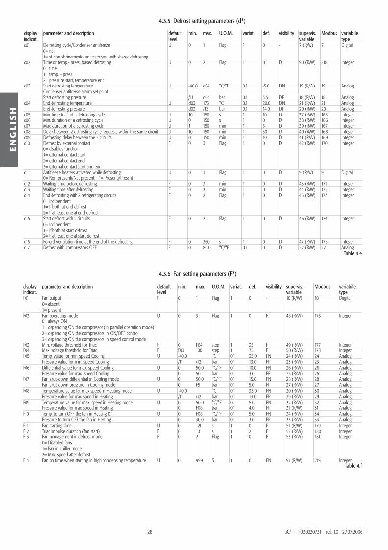
4.3.5 Defrost setting parameters (d*)
display indicat.
parameter and description default level
min. max. U.O.M. variat. def. visibility supervis. variable
Modbus variabile type
d01 Defrosting cycle/Condenser antifreeze0= no; 1= sì, con sbrinamento unifi cato yes, with shared defrosting
U 0 1 Flag 1 0 - 7 (R/W) 7 Digital
d02 Time or temp.- press. based defrosting0= time1= temp. - press2= pressure start, temperature end
U 0 2 Flag 1 0 D 90 (R/W) 218 Integer
d03
Start defrosting temperature Condenser antifreeze alarm set point
U -40.0 d04 °C/°F 0.1 -5.0 DN 19 (R/W) 19 Analog
Start defrosting pressure /11 d04 bar 0.1 3.5 DP 18 (R/W) 18 Analogd04
End defrosting temperature U d03 176 °C 0.1 20.0 DN 21 (R/W) 21 Analog End defrosting pressure d03 /12 bar 0.1 14.0 DP 20 (R/W) 20 Analog
d05 Min. time to start a defrosting cycle U 10 150 s 1 10 D 37 (R/W) 165 Integerd06 Min. duration of a defrosting cycle U 0 150 s 1 0 D 38 (R/W) 166 Integerd07 Max. duration of a defrosting cycle U 1 150 min 1 5 D 39 (R/W) 167 Integerd08 Delay between 2 defrosting cycle requests within the same circuit U 10 150 min 1 30 D 40 (R/W) 168 Integerd09 Defrosting delay between the 2 circuits U 0 150 min 1 10 D 41 (R/W) 169 Integerd10 Defrost by external contact
0= disables function1= external contact start2= external contact end3= external contact start and end
F 0 3 Flag 1 0 D 42 (R/W) 170 Integer
d11 Antifreeze heaters activated while defrosting0= Non presenti/Not present; 1= Presenti/Present
U 0 1 Flag 1 0 D 9 (R/W) 9 Digital
d12 Waiting time before defrosting F 0 3 min 1 0 D 43 (R/W) 171 Integerd13 Waiting time after defrosting F 0 3 min 1 0 D 44 (R/W) 172 Integerd14 End defrosting with 2 refrigerating circuits
0= Indipendent1= If both at end defrost2= If at least one at end defrost
F 0 2 Flag 1 0 D 45 (R/W) 173 Integer
d15 Start defrost with 2 circuits0= Indipendent1= If both at start defrost2= If at least one at start defrost
F 0 2 Flag 1 0 D 46 (R/W) 174 Integer
d16 Forced ventilation time at the end of the defrosting F 0 360 s 1 0 D 47 (R/W) 175 Integerd17 Defrost with compressors OFF F 0 80.0 °C/°F 0.1 0 D 22 (R/W) 22 Analog
Table 4.e
4.3.6 Fan setting parameters (F*)
display indicat.
parameter and description default level
min. max. U.O.M. variat. def. visibility supervis. variable
Modbus variabile type
F01 Fan output 0= absent1= present
F 0 1 Flag 1 0 - 10 (R/W) 10 Diigital
F02 Fan operating mode0= always ON1= depending ON the compressor (in parallel operation mode)2= depending ON the compressors in ON/OFF control3= depending ON the compressors in speed control mode
U 0 3 Flag 1 0 F 48 (R/W) 176 Integer
F03 Min. voltage threshold for Triac F 0 F04 step 1 35 F 49 (R/W) 177 IntegerF04 Max. voltage threshold for Triac F F03 100 step 1 75 F 50 (R/W) 178 IntegerF05
Temp. value for min. speed Cooling U -40.0 °C 0.1 35.0 FN 24 (R/W) 24 Analog Pressure value for min. speed Cooling /11 /12 bar 0.1 13.0 FP 23 (R/W) 23 Analog
F06
Differential value for max. speed Cooling U 0 50.0 °C/°F 0.1 10.0 FN 26 (R/W) 26 Analog Pressure value for max. speed Cooling 0 50 bar 0.1 3.0 FP 25 (R/W) 25 Analog
F07
Fan shut-down differential in Cooling mode U 0 50.0 °C/°F 0.1 15.0 FN 28 (R/W) 28 Analog Fan shut-down pressure in Cooling mode 0 F5 bar 0.1 5.0 FP 27 (R/W) 27 Analog
F08
Temperature value for max speed in Heating mode U -40.0 °C 0.1 35.0 FN 30 (R/W) 30 Analog Pressure value for max speed in Heating /11 /12 bar 0.1 13.0 FP 29 (R/W) 29 Analog
F09
Temperature value for max. speed in Heating mode U 0 50.0 °C/°F 0.1 5.0 FN 32 (R/W) 32 Analog Pressure value for max speed in Heating 0 F08 bar 0.1 4.0 FP 31 (R/W) 31 Analog
F10
Temp. to turn OFF the fan in Heating 0.1 U 0 F08 °C/°F 0.1 5.0 FN 34 (R/W) 34 Analog Pressure to turn OFF the fan in Heating 0 30.0 bar 0.1 3.0 FP 33 (R/W) 33 Analog
F11 Fan starting time U 0 120 s 1 0 F 51 (R/W) 179 IntegerF12 Triac impulse duration (fan start) F 0 10 s 1 2 F 52 (R/W) 180 IntegerF13 Fan management in defrost mode
0= Disabled fans1= Fan in chiller mode2= Max. speed after defrost
F 0 2 Flag 1 0 F 53 (R/W) 181 Integer
F14 Fan on time when starting in high condensing temperature U 0 999 S 1 0 FN 91 (R/W) 219 IntegerTable 4.f
29
EN
GL
ISH
µC2 - +030220731 - rel. 1.0 - 27.07.2006
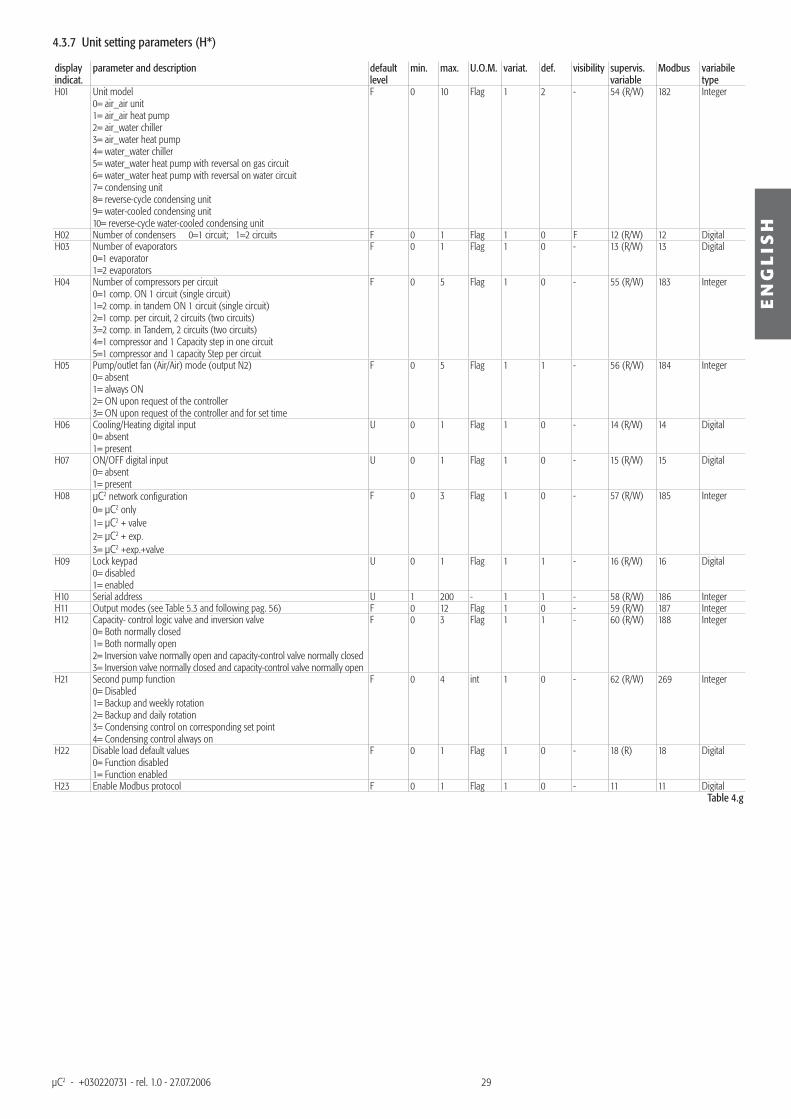
4.3.7 Unit setting parameters (H*)
display indicat.
parameter and description default level
min. max. U.O.M. variat. def. visibility supervis. variable
Modbus variabile type
H01 Unit model 0= air_air unit1= air_air heat pump2= air_water chiller3= air_water heat pump4= water_water chiller5= water_water heat pump with reversal on gas circuit6= water_water heat pump with reversal on water circuit 7= condensing unit8= reverse-cycle condensing unit9= water-cooled condensing unit10= reverse-cycle water-cooled condensing unit
F 0 10 Flag 1 2 - 54 (R/W) 182 Integer
H02 Number of condensers 0=1 circuit; 1=2 circuits F 0 1 Flag 1 0 F 12 (R/W) 12 DigitalH03 Number of evaporators
0=1 evaporator1=2 evaporators
F 0 1 Flag 1 0 - 13 (R/W) 13 Digital
H04 Number of compressors per circuit0=1 comp. ON 1 circuit (single circuit)1=2 comp. in tandem ON 1 circuit (single circuit)2=1 comp. per circuit, 2 circuits (two circuits)3=2 comp. in Tandem, 2 circuits (two circuits)4=1 compressor and 1 Capacity step in one circuit5=1 compressor and 1 capacity Step per circuit
F 0 5 Flag 1 0 - 55 (R/W) 183 Integer
H05 Pump/outlet fan (Air/Air) mode (output N2)0= absent1= always ON2= ON upon request of the controller3= ON upon request of the controller and for set time
F 0 5 Flag 1 1 - 56 (R/W) 184 Integer
H06 Cooling/Heating digital input0= absent1= present
U 0 1 Flag 1 0 - 14 (R/W) 14 Digital
H07 ON/OFF digital input 0= absent1= present
U 0 1 Flag 1 0 - 15 (R/W) 15 Digital
H08 µC2 network confi guration0= µC2 only1= µC2 + valve2= µC2 + exp.3= µC2 +exp.+valve
F 0 3 Flag 1 0 - 57 (R/W) 185 Integer
H09 Lock keypad 0= disabled 1= enabled
U 0 1 Flag 1 1 - 16 (R/W) 16 Digital
H10 Serial address U 1 200 - 1 1 - 58 (R/W) 186 IntegerH11 Output modes (see Table 5.3 and following pag. 56) F 0 12 Flag 1 0 - 59 (R/W) 187 IntegerH12 Capacity- control logic valve and inversion valve
0= Both normally closed 1= Both normally open2= Inversion valve normally open and capacity-control valve normally closed3= Inversion valve normally closed and capacity-control valve normally open
F 0 3 Flag 1 1 - 60 (R/W) 188 Integer
H21 Second pump function0= Disabled1= Backup and weekly rotation2= Backup and daily rotation3= Condensing control on corresponding set point4= Condensing control always on
F 0 4 int 1 0 - 62 (R/W) 269 Integer
H22 Disable load default values0= Function disabled1= Function enabled
F 0 1 Flag 1 0 - 18 (R) 18 Digital
H23 Enable Modbus protocol F 0 1 Flag 1 0 - 11 11 DigitalTable 4.g
30
EN
GL
ISH
µC2 - +030220731 - rel. 1.0 - 27.07.2006
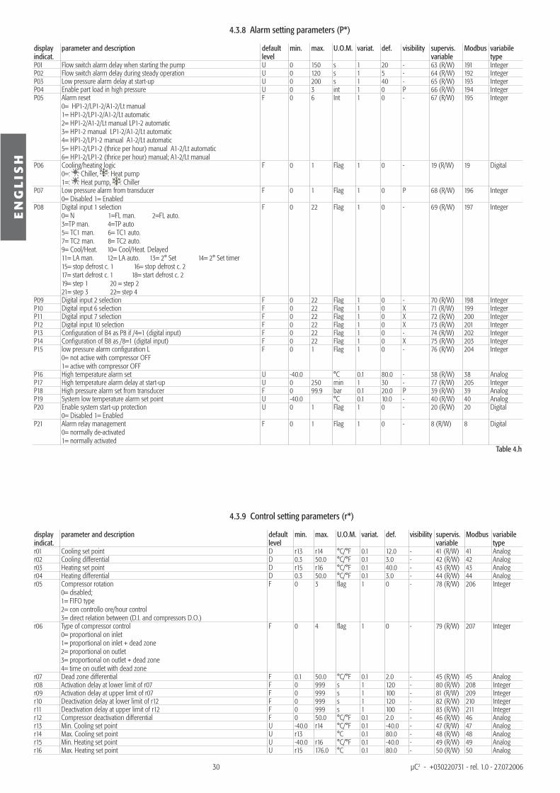
4.3.8 Alarm setting parameters (P*)
display indicat.
parameter and description default level
min. max. U.O.M. variat. def. visibility supervis. variable
Modbus variabile type
P01 Flow switch alarm delay when starting the pump U 0 150 s 1 20 - 63 (R/W) 191 IntegerP02 Flow switch alarm delay during steady operation U 0 120 s 1 5 - 64 (R/W) 192 IntegerP03 Low pressure alarm delay at start-up U 0 200 s 1 40 - 65 (R/W) 193 IntegerP04 Enable part load in high pressure U 0 3 int 1 0 P 66 (R/W) 194 IntegerP05 Alarm reset
0= HP1-2/LP1-2/A1-2/Lt manual1= HP1-2/LP1-2/A1-2/Lt automatic2= HP1-2/A1-2/Lt manual LP1-2 automatic3= HP1-2 manual LP1-2/A1-2/Lt automatic4= HP1-2/LP1-2 manual A1-2/Lt automatic5= HP1-2/LP1-2 (thrice per hour) manual A1-2/Lt automatic6= HP1-2/LP1-2 (thrice per hour) manual; A1-2/Lt manual
F 0 6 Int 1 0 - 67 (R/W) 195 Integer
P06 Cooling/heating logic 0=: Chiller, : Heat pump 1=: Heat pump, : Chiller
F 0 1 Flag 1 0 - 19 (R/W) 19 Digital
P07 Low pressure alarm from transducer 0= Disabled 1= Enabled
F 0 1 Flag 1 0 P 68 (R/W) 196 Integer
P08 Digital input 1 selection 0= N 1=FL man. 2=FL auto. 3=TP man. 4=TP auto 5= TC1 man. 6= TC1 auto. 7= TC2 man. 8= TC2 auto. 9= Cool/Heat. 10= Cool/Heat. Delayed 11= LA man. 12= LA auto. 13= 2° Set 14= 2° Set timer 15= stop defrost c. 1 16= stop defrost c. 2 17= start defrost c. 1 18= start defrost c. 2 19= step 1 20 = step 2 21= step 3 22= step 4
F 0 22 Flag 1 0 - 69 (R/W) 197 Integer
P09 Digital input 2 selection F 0 22 Flag 1 0 - 70 (R/W) 198 IntegerP10 Digital input 6 selection F 0 22 Flag 1 0 X 71 (R/W) 199 IntegerP11 Digital input 7 selection F 0 22 Flag 1 0 X 72 (R/W) 200 IntegerP12 Digital input 10 selection F 0 22 Flag 1 0 X 73 (R/W) 201 IntegerP13 Confi guration of B4 as P8 if /4=1 (digital input) F 0 22 Flag 1 0 - 74 (R/W) 202 IntegerP14 Confi guration of B8 as /8=1 (digital input) F 0 22 Flag 1 0 X 75 (R/W) 203 IntegerP15 low pressure alarm confi guration L
0= not active with compressor OFF1= active with compressor OFF
F 0 1 Flag 1 0 - 76 (R/W) 204 Integer
P16 High temperature alarm set U -40.0 °C 0.1 80.0 - 38 (R/W) 38 AnalogP17 High temperature alarm delay at start-up U 0 250 min 1 30 - 77 (R/W) 205 IntegerP18 High pressure alarm set from transducer F 0 99.9 bar 0.1 20.0 P 39 (R/W) 39 AnalogP19 System low temperature alarm set point U -40.0 °C 0.1 10.0 - 40 (R/W) 40 AnalogP20 Enable system start-up protection
0= Disabled 1= EnabledU 0 1 Flag 1 0 - 20 (R/W) 20 Digital
P21 Alarm relay management 0= normally de-activated1= normally activated
F 0 1 Flag 1 0 - 8 (R/W) 8 Digital
Table 4.h
4.3.9 Control setting parameters (r*)
display indicat.
parameter and description default level
min. max. U.O.M. variat. def. visibility supervis. variable
Modbus variabile type
r01 Cooling set point D r13 r14 °C/°F 0.1 12.0 - 41 (R/W) 41 Analogr02 Cooling differential D 0.3 50.0 °C/°F 0.1 3.0 - 42 (R/W) 42 Analogr03 Heating set point D r15 r16 °C/°F 0.1 40.0 - 43 (R/W) 43 Analogr04 Heating differential D 0.3 50.0 °C/°F 0.1 3.0 - 44 (R/W) 44 Analogr05 Compressor rotation
0= disabled; 1= FIFO type 2= con controllo ore/hour control3= direct relation between (D.I. and compressors D.O.)
F 0 3 fl ag 1 0 - 78 (R/W) 206 Integer
r06 Type of compressor control0= proportional on inlet 1= proportional on inlet + dead zone2= proportional on outlet3= proportional on outlet + dead zone4= time on outlet with dead zone
F 0 4 fl ag 1 0 - 79 (R/W) 207 Integer
r07 Dead zone differential F 0.1 50.0 °C/°F 0.1 2.0 - 45 (R/W) 45 Analogr08 Activation delay at lower limit of r07 F 0 999 s 1 120 - 80 (R/W) 208 Integerr09 Activation delay at upper limit of r07 F 0 999 s 1 100 - 81 (R/W) 209 Integerr10 Deactivation delay at lower limit of r12 F 0 999 s 1 120 - 82 (R/W) 210 Integerr11 Deactivation delay at upper limit of r12 F 0 999 s 1 100 - 83 (R/W) 211 Integerr12 Compressor deactivation differential F 0 50.0 °C/°F 0.1 2.0 - 46 (R/W) 46 Analogr13 Min. Cooling set point U -40.0 r14 °C/°F 0.1 -40.0 - 47 (R/W) 47 Analogr14 Max. Cooling set point U r13 °C 0.1 80.0 - 48 (R/W) 48 Analogr15 Min. Heating set point U -40.0 r16 °C/°F 0.1 -40.0 - 49 (R/W) 49 Analogr16 Max. Heating set point U r15 176.0 °C 0.1 80.0 - 50 (R/W) 50 Analog
31
EN
GL
ISH
µC2 - +030220731 - rel. 1.0 - 27.07.2006
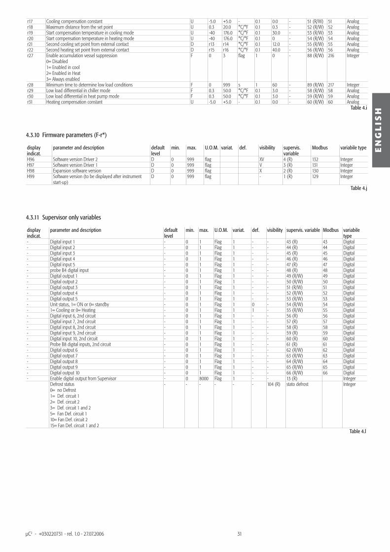
r17 Cooling compensation constant U -5.0 +5.0 - 0.1 0.0 - 51 (R/W) 51 Analogr18 Maximum distance from the set point U 0.3 20.0 °C/°F 0.1 0.3 - 52 (R/W) 52 Analogr19 Start compensation temperature in cooling mode U -40 176.0 °C/°F 0.1 30.0 - 53 (R/W) 53 Analogr20 Start compensation temperature in heating mode U -40 176.0 °C/°F 0.1 0 - 54 (R/W) 54 Analogr21 Second cooling set point from external contact D r13 r14 °C/°F 0.1 12.0 - 55 (R/W) 55 Analogr22 Second heating set point from external contact D r15 r16 °C/°F 0.1 40.0 - 56 (R/W) 56 Analogr27 Enable accumulation vessel suppression
0= Disabled1= Enabled in cool2= Enabled in Heat3= Always enabled
F 0 3 fl ag 1 0 - 88 (R/W) 216 Integer
r28 Minimum time to determine low load conditions F 0 999 s 1 60 - 89 (R/W) 217 Integerr29 Low load differential in chiller mode F 0.3 50.0 °C/°F 0.1 3.0 - 58 (R/W) 58 Analogr30 Low load differential in heat pump mode F 0.3 50.0 °C/°F 0.1 3.0 - 59 (R/W) 59 Analogr31 Heating compensation constant U -5.0 +5.0 - 0.1 0.0 - 60 (R/W) 60 Analog
Table 4.i
4.3.10 Firmware parameters (F-r*)
display indicat.
parameter and description default level
min. max. U.O.M. variat. def. visibility supervis. variable
Modbus variabile type
H96 Software version Driver 2 D 0 999 fl ag XV 4 (R) 132 IntegerH97 Software version Driver 1 D 0 999 fl ag V 3 (R) 131 IntegerH98 Expansion software version D 0 999 fl ag X 2 (R) 130 IntegerH99 Software version (to be displayed after instrument
start-up)D 0 999 fl ag - 1 (R) 129 Integer
Table 4.j
4.3.11 Supervisor only variables
display indicat.
parameter and description default level
min. max. U.O.M. variat. def. visibility supervis. variable Modbus variabile type
- Digital input 1 - 0 1 Flag 1 - - 43 (R) 43 Digital- Digital input 2 - 0 1 Flag 1 - - 44 (R) 44 Digital- Digital input 3 - 0 1 Flag 1 - - 45 (R) 45 Digital- Digital input 4 - 0 1 Flag 1 - - 46 (R) 46 Digital- Digital input 5 - 0 1 Flag 1 - - 47 (R) 47 Digital- probe B4 digital input - 0 1 Flag 1 - - 48 (R) 48 Digital- Digital output 1 - 0 1 Flag 1 - - 49 (R/W) 49 Digital- Digital output 2 - 0 1 Flag 1 - - 50 (R/W) 50 Digital- Digital output 3 - 0 1 Flag 1 - - 51 (R/W) 51 Digital- Digital output 4 - 0 1 Flag 1 - - 52 (R/W) 52 Digital- Digital output 5 - 0 1 Flag 1 - - 53 (R/W) 53 Digital- Unit status, 1= ON or 0= standby - 0 1 Flag 1 0 - 54 (R/W) 54 Digital- 1= Cooling or 0= Heating - 0 1 Flag 1 1 - 55 (R/W) 55 Digital- Digital input 6, 2nd circuit - 0 1 Flag 1 - - 56 (R) 56 Digital- Digital input 7, 2nd circuit - 0 1 Flag 1 - - 57 (R) 57 Digital- Digital input 8, 2nd circuit - 0 1 Flag 1 - - 58 (R) 58 Digital- Digital input 9, 2nd circuit - 0 1 Flag 1 - - 59 (R) 59 Digital- Digital input 10, 2nd circuit - 0 1 Flag 1 - - 60 (R) 60 Digital- Probe B8 digital inputs, 2nd circuit - 0 1 Flag 1 - - 61 (R) 61 Digital- Digital output 6 - 0 1 Flag 1 - - 62 (R/W) 62 Digital- Digital output 7 - 0 1 Flag 1 - - 63 (R/W) 63 Digital- Digital output 8 - 0 1 Flag 1 - - 64 (R/W) 64 Digital- Digital output 9 - 0 1 Flag 1 - - 65 (R/W) 65 Digital- Digital output 10 - 0 1 Flag 1 - - 66 (R/W) 66 Digital- Enable digital output from Supervisor - 0 8000 Flag 1 - - 13 (R) Integer Defrost status
0= no Defrost 1= Def. circuit 1 2= Def. circuit 2 3= Def. circuit 1 and 2 5= Fan Def. circuit 110= Fan Def. circuit 215= Fan Def. circuit 1 and 2
- - - - - - 104 (R) stato defrost Integer
Table 4.l
MOTIVAIR MANUAL for MPC-A 0500 - 7200 FRONT PANEL
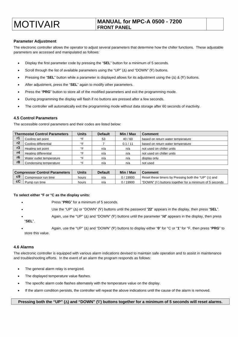
Parameter Adjustment The electronic controller allows the operator to adjust several parameters that determine how the chiller functions. These adjustable parameters are accessed and manipulated as follows:
• Display the first parameter code by pressing the “SEL” button for a minimum of 5 seconds.
• Scroll through the list of available parameters using the “UP” (Δ) and “DOWN” (∇) buttons.
• Pressing the “SEL” button while a parameter is displayed allows for its adjustment using the (Δ) & (∇) buttons.
• After adjustment, press the “SEL” again to modify other parameters.
• Press the “PRG” button to store all of the modified parameters and exit the programming mode.
• During programming the display will flash if no buttons are pressed after a few seconds.
• The controller will automatically exit the programming mode without data storage after 60 seconds of inactivity.
4.5 Control Parameters The accessible control parameters and their codes are listed below: Thermostat Control Parameters Units Default Min / Max Comment
r1 Cooling set point °F 53 40 / 60 based on return water temperature r2 Cooling differential °F 7 0.1 / 11 based on return water temperature r3 Heating set point °F n/a n/a not used on chiller units r4 Heating differential °F n/a n/a not used on chiller units r6 Water outlet temperature °F n/a n/a display onlyr8 Condensing temperature °F n/a n/a not used
Compressor Control Parameters Units Default Min / Max Commentc9 Compressor run time hours n/a 0 / 19900cC Pump run time hours n/a 0 / 19900
Reset these timers by Pressing both the “UP” (Δ) and “DOWN” (∇) buttons together for a minimum of 5 seconds
To select either °F or °C as the display units:
• Press “PRG” for a minimum of 5 seconds.
• Use the “UP” (Δ) or “DOWN” (∇) buttons until the password “22” appears in the display, then press “SEL”.
• Again, use the “UP” (Δ) and “DOWN” (∇) buttons until the parameter “/d” appears in the display, then press “SEL”.
• Again, use the “UP” (Δ) and “DOWN” (∇) buttons to display either “0” for °C or “1” for °F, then press “PRG” to store this value.
4.6 Alarms The electronic controller is equipped with various alarm indications devised to maintain safe operation and to assist in maintenance and troubleshooting efforts. In the event of an alarm the program responds as follows:
• The general alarm relay is energized.
• The displayed temperature value flashes.
• The specific alarm code flashes alternately with the temperature value on the display.
• If the alarm condition persists, the controller will repeat the above indications until the cause of the alarm is removed.
Pressing both the “UP” (Δ) and “DOWN” (∇) buttons together for a minimum of 5 seconds will reset alarms.
MOTIVAIR MANUAL for MPC-A 0500 - 7200 FRONT PANEL
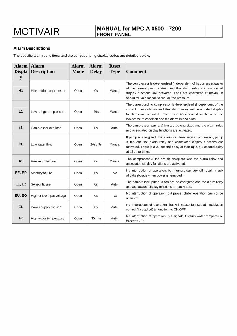
Alarm Descriptions
The specific alarm conditions and the corresponding display codes are detailed below: Alarm Displa
y
Alarm Description
Alarm Mode
AlarmDelay
Reset Type
Comment
H1 High refrigerant pressure Open 0s Manual
The compressor is de-energized (independent of its current status or of the current pump status) and the alarm relay and associated display functions are activated. Fans are energized at maximum speed for 60 seconds to reduce the pressure.
L1 Low refrigerant pressure Open 40s Manual
The corresponding compressor is de-energized (independent of the current pump status) and the alarm relay and associated display functions are activated. There is a 40-second delay between the low-pressure condition and the alarm intervention.
t1 Compressor overload Open 0s Auto. The compressor, pump, & fan are de-energized and the alarm relay and associated display functions are activated.
FL Low water flow Open 20s / 5s Manual
If pump is energized, this alarm will de-energize compressor, pump & fan and the alarm relay and associated display functions are activated. There is a 20-second delay at start-up & a 5-second delay at all other times.
A1 Freeze protection Open 0s Manual The compressor & fan are de-energized and the alarm relay and associated display functions are activated.
EE, EP Memory failure Open 0s n/a No interruption of operation, but memory damage will result in lack of data storage when power is removed.
E1, E2 Sensor failure Open 0s Auto. The compressor, pump, & fan are de-energized and the alarm relay and associated display functions are activated.
EU, EO High or low input voltage Open 0s n/a No interruption of operation, but proper chiller operation can not be assured.
EL Power supply “noise” Open 0s Auto. No interruption of operation, but will cause fan speed modulation control (if supplied) to function as ON/OFF.
Ht High water temperature Open 30 min Auto. No interruption of operation, but signals if return water temperature exceeds 70°F
MOTIVAIR MANUAL for MPC-A 0005-MPC-A 7200 COMMISSIONING/START-UP
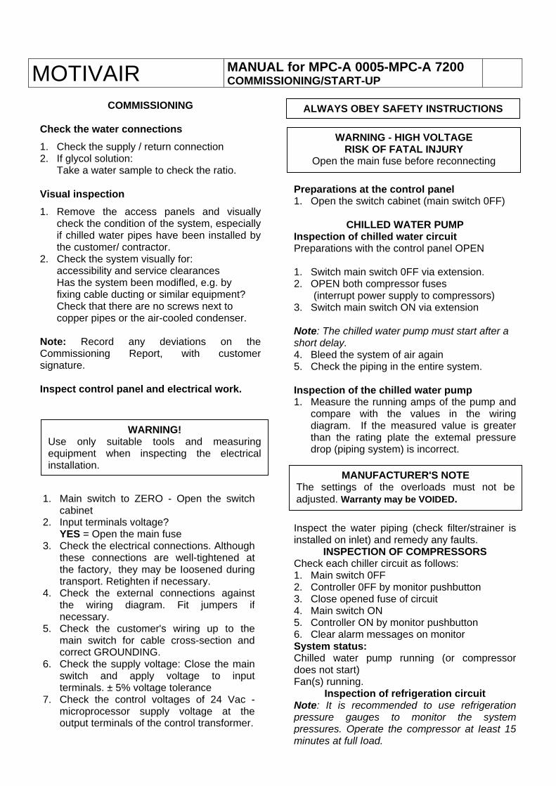
COMMISSIONING Check the water connections 1. Check the supply / return connection 2. If glycol solution:
Take a water sample to check the ratio. VisuaI inspection 1. Remove the access panels and visually
check the condition of the system, especiallyif chilled water pipes have been installed bythe customer/ contractor.
2. Check the system visually for: accessibility and service clearances Has the system been modifled, e.g. by fixing cable ducting or similar equipment? Check that there are no screws next to copper pipes or the air-cooled condenser.
Note: Record any deviations on theCommissioning Report, with customersignature. Inspect control panel and electrical work.
ALWAYS OBEY SAFETY INSTRUCTIONS
WARNING - HIGH VOLTAGE RISK OF FATAL INJURY
Open the main fuse before reconnecting
Preparations at the control panel 1. Open the switch cabinet (main switch 0FF)
CHILLED WATER PUMP Inspection of chilled water circuit Preparations with the control panel OPEN 1. Switch main switch 0FF via extension. 2. OPEN both compressor fuses
(interrupt power supply to compressors) 3. Switch main switch ON via extension Note: The chilled water pump must start after a short delay. 4. Bleed the system of air again 5. Check the piping in the entire system. Inspection of the chilled water pump 1. Measure the running amps of the pump and
compare with the values in the wiringdiagram. If the measured value is greaterthan the rating plate the extemal pressuredrop (piping system) is incorrect.
WARNING! Use only suitable tools and measuringequipment when inspecting the electricalinstallation. MANUFACTURER'S NOTE
The settings of the overloads must not beadjusted. Warranty may be VOIDED. 1. Main switch to ZERO - Open the switch
cabinet 2. Input terminals voltage?
YES = Open the main fuse 3. Check the electrical connections. Although
these connections are well-tightened atthe factory, they may be Ioosened duringtransport. Retighten if necessary.
4. Check the external connections againstthe wiring diagram. Fit jumpers ifnecessary.
5. Check the customer's wiring up to themain switch for cable cross-section andcorrect GROUNDING.
6. Check the supply voltage: Close the mainswitch and apply voltage to inputterminals. ± 5% voltage tolerance
7. Check the control voltages of 24 Vac -microprocessor supply voltage at theoutput terminals of the control transformer.
Inspect the water piping (check filter/strainer isinstalled on inlet) and remedy any faults.
INSPECTION OF COMPRESSORS Check each chiller circuit as follows: 1. Main switch 0FF 2. Controller 0FF by monitor pushbutton 3. Close opened fuse of circuit 4. Main switch ON 5. Controller ON by monitor pushbutton 6. Clear alarm messages on monitor System status: Chilled water pump running (or compressordoes not start) Fan(s) running.
Inspection of refrigeration circuit Note: It is recommended to use refrigerationpressure gauges to monitor the systempressures. Operate the compressor at Ieast 15minutes at full Ioad.
MOTIVAIR MANUAL for MPC-A 0005- MPC-A 7200 COMMISSIONING INSTRUCTIONS
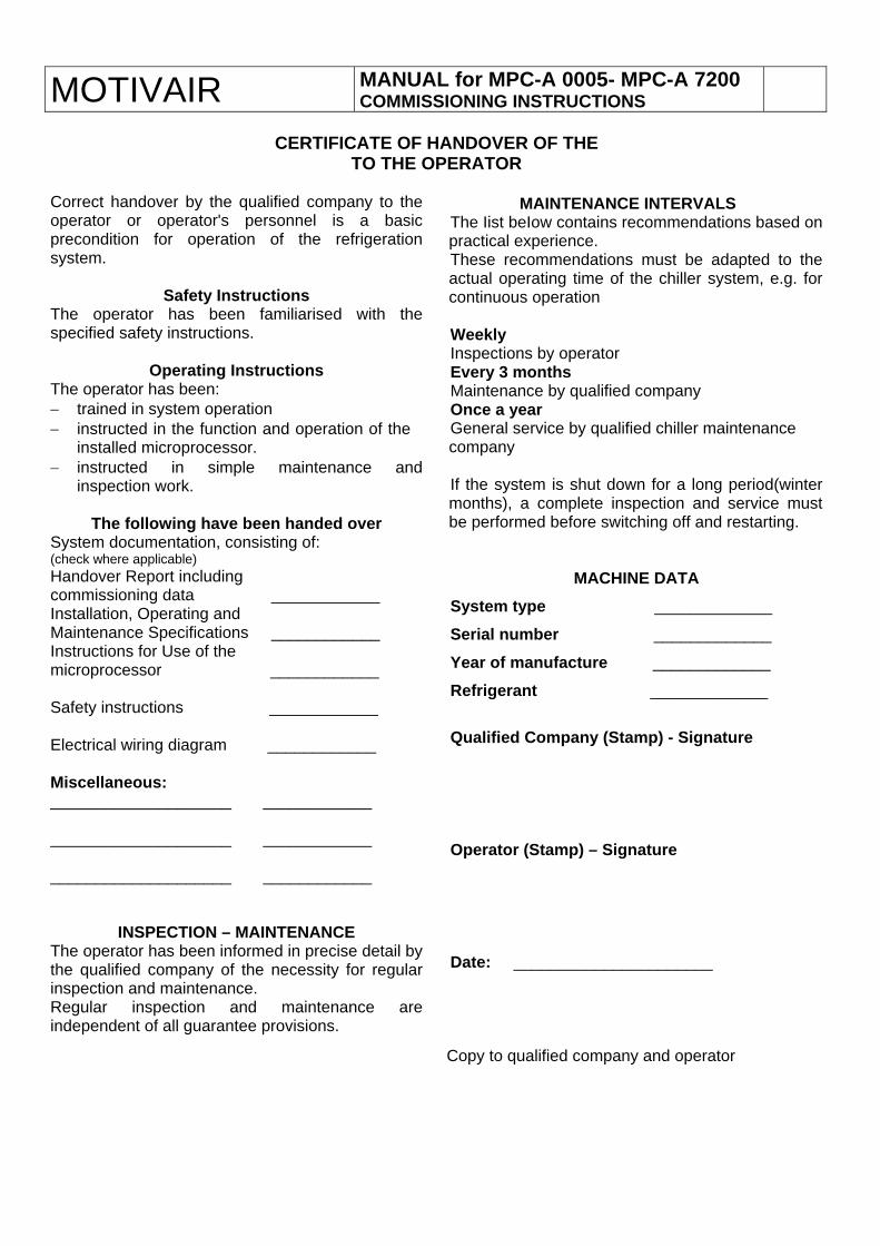
CERTIFICATE OF HANDOVER OF THE
TO THE OPERATOR Correct handover by the qualified company to the operator or operator's personnel is a basic precondition for operation of the refrigeration system.
Safety Instructions The operator has been familiarised with the specified safety instructions.
Operating Instructions The operator has been: − trained in system operation − instructed in the function and operation of the
installed microprocessor. − instructed in simple maintenance and
inspection work.
The following have been handed over System documentation, consisting of: (check where applicable) Handover Report including commissioning data ____________ Installation, Operating and Maintenance Specifications ____________ Instructions for Use of the microprocessor ____________ Safety instructions ____________ Electrical wiring diagram ____________ Miscellaneous: ____________________ ____________ ____________________ ____________ ____________________ ____________
INSPECTION – MAINTENANCE The operator has been informed in precise detail by the qualified company of the necessity for regular inspection and maintenance. Regular inspection and maintenance are independent of all guarantee provisions.
MAINTENANCE INTERVALS
The Iist beIow contains recommendations based on practical experience. These recommendations must be adapted to the actual operating time of the chiller system, e.g. for continuous operation Weekly Inspections by operator Every 3 months Maintenance by qualified company Once a year General service by qualified chiller maintenance company
If the system is shut down for a long period(winter months), a complete inspection and service must be performed before switching off and restarting.
MACHINE DATA System type _____________
Serial number _____________
Year of manufacture _____________
Refrigerant _____________
Qualified Company (Stamp) - Signature Operator (Stamp) – Signature Date: ______________________
Copy to qualified company and operator

MOTIVAIR MANUAL for MPC-A 0005- MPC-A 7200 COMMISSIONING REPORT
The system was commissioned under the following conditions
Ambient air temperature Chilled water inlet temperature Chilled water outlet temperature GIycoI solution Type of glycol Name. Water flow rate Pressure drop Refrig. circuit 1 - Compressor 1 Power consumption,compressor Power consumption1compressor Power consumption1compressor Overcurrent release1 winding 1 Overcurrent release,winding 2 High pressure Low pressure OiI pressure (semi hermetic only) Suction gas temperature Superheat Safety devices – Settings Highpressure SDBK High pressure DBK OiI pressure OFF/SEC Low pressure OFF/ON Refrig. Circuit 1 - Compressor 2 Power consumption,compressor Power consumption1compressor Power consumption1compressor Overcurrent release1 winding 1 Overcurrent release,winding 2 High pressure Low pressure OiI pressure (semi hermetic) Intake gas temperature Overheating Safety devices – Settings Highpressure SDBK High pressure DBK OiI pressure OFF/SEC Low pressure OFF/ON Pump 1 Power consumption Power consumption Power consumption Overcurrent release Pressure gauge, intake Pressure gauge, delivery
°F °F °F % GPM PSI L1/A L2/A L3/A A A PSIG PSIG PSIG °F K PSIG PSIG PSIG PSIG L1/A L2/A L3/A A A PSIG PSIG PSIG °F K PSIG PSIG PSIG PSIG L1/A L2/A L3/A A PSIG PSIG
Pump 2 Power consumption Power consumption Power consumption Overcurrent release Pressure gauge, intake Pressure gauge, delivery
lnspection of safety system Antifreeze cut-off temperature FIow meter switch point
Control settings Return temperature Supply temperature Setpoint Values read by the probes
System ID Model Series/Year of manufacture Customer Job No Supplier Order No Refrigerant Type: Lbs. circ.1 Lbs. circ.2 Operator/installation site: ___________________________________Start up company ___________________________________The system was commissioned without deficiency. The Iisted values were measured at full Ioad. ___________________________________Date/Place ___________________________________System operator ___________________________________Contact person of performing company: ___________________________________Servicing – Technical ___________________________________Comments:
L1/A L2/A L3/A A PSIG PSIG °F Mark °F °F °F

MOTIVAIR MANUAL for MPC-A 0005- MPC-A 7200 TROUBLESHOOTING
WWAARRNNIINNGG OOBBEEYY AALLLL SSAAFFEETTYY IINNSSTTRRUUCCTTIIOONNSS
The table that follows lists a large proportion ofthe fault causes that can occur in practice. These descriptions are intended for informationonly and must not be considered as a repairmanual. Often, the cause of a failure is due to a variety offactors. However, these factors can only be evaluated bya qualified refrigeration company with preciseknowledge of the functional interactions.
WWAARRNNIINNGG OOnnllyy qquuaalliiffiieedd sseerrvviiccee aanndd MMaaiinntteennaannccee ppeerrssoonnnneell mmaayy ccaarrrryy oouutt rreeppaaiirrssttoo tthhee ssyysstteemm.. DDuurriinngg ooppeerraattiioonn,,ppootteennttiiaallllyyffaattaall pprreessssuurreess aanndd vvoollttaaggeess aarree ggeenneerraatteedd iinntthhee ssyysstteemm.. AAllll ssaaffeettyy pprreeccaauuttiioonnss aanndd wwaarrnniinnggss ccoonnttaaiinneeddiinn tthheessee ddooccuummeennttss mmuusstt bbee ssttrriiccttllyy oobbsseerrvveedd..
PPoossssiibbllee mmaallffuunnccttiioonnss ttoo tthhee cchhiilllleerr mmaayy ooccccuurr dduueettoo tthhee ffoolllloowwiinngg ffaaccttoorrss::
11.. CChhaannggeess iinn ooppeerraattiinngg ccoonnddiittiioonnss
22.. llnnssuuffffiicciieenntt mmaaiinntteennaannccee aanndd iinnssppeeccttiioonn
33.. EExxtteerrnnaall eennvviirroonnmmeennttaall ffaaccttoorrss
44.. IInntteerrnnaall mmaacchhiinnee ffaaccttoorrss
55.. SSyysstteemm ffaaccttoorrss
66.. OOppeerraattiinngg eerrrroorrss
CCAAUUSSEESS OOFF MMAALLFFUUNNCCTTIIOONNSS TThheessee ccaauusseess ccaann bbee ddiivviiddeedd iinnttoo tthhrreeee ggrroouuppss:: 11.. FFaauullttss dduuee ttoo tthhee wwaatteerr cciirrccuuiitt
TThhee ooppeerraattoorr ccaann ggeenneerraallllyy rreemmeeddyy tthhiiss ttyyppee ooffpprroobblleemm..
22.. EElleeccttrriiccaall ffaauullttss WWiitthh tthhee aaiidd ooff aa qquuaalliiffiieedd eelleeccttrriicciiaann,, tthheeooppeerraattoorr ccaann ppaarrttiiaallllyy rreemmeeddyy tthhiiss ttyyppee ooff ffaauulltt..
33.. FFaauullttss iinn tthhee rreeffrriiggeerraanntt cciirrccuuiitt..
TThhiiss ttyyppee ooff pprroobblleemm ccaann oonnllyy bbee rreemmeeddiieedd bbyyaa qquuaalliiffiieedd rreeffrriiggeerraattiioonn ccoommppaannyy..
IMPORTANT A large proportion of the functions, faults and
operating states of the system are signalled by the microprocessor.
The microprocessor monitors all the function areas of the system.
Therefore, this information is also essential in defining faults.
CHANGES IN OPERATING CONDITIONS Significant changes in the operating conditions of
the liquid chiller may cause faults, because individual components important to the operation
of the system wiII not be tuned to the new operating mode.
Inform the MANUFACTURER of any intended change and obtain prior consent.
NOTE: CANCELLATION OF WARRANTY MAY OCCUR.
TROUBLESHOOTING
FAULTS,
possible CAUSES
and possible REMEDIES
MOTIVAIR MANUAL for MPC-A 0005- MPC-A 7200 TROUBLESHOOTING
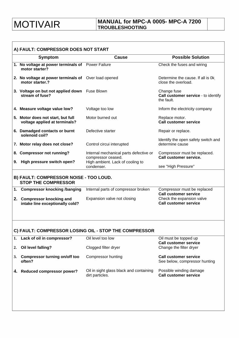
A) FAULT: COMPRESSOR DOES NOT START
Symptom Cause Possible Solution 1. No voltage at power terminals of
motor starter? 2. No voltage at power terminals of
motor starter.? 3. Voltage on but not applied down
stream of fuse? 4. Measure voltage value low? 5. Motor does not start, but full
voltage applied at terminals? 6. Damadged contacts or burnt
solenoid coil? 7. Motor relay does not close? 8. Compressor not running? 9. High pressure switch open?
Power Failure Over load opened Fuse Blown Voltage too low Motor burned out Defective starter Control circui interupted Internal mechanical parts defective or compressor ceased. High ambient. Lack of cooling to condenser.
Check the fuses and wiring Determine the cause. lf all is 0k, close the overload. Change fuse Call customer service - to identify the fault. Inform the electricity company Replace motor. Call customer service Repair or replace. ldentify the open safety switch and determine cause Compressor must be replaced. Call customer service. see "High Pressure”
B) FAULT: COMPRESSOR NOISE - TOO LOUD. STOP THE COMPRESSOR 1. Compressor knocking /banging 2. Compressor knocking and
intake line exceptionally cold?
Internal parts of compressor broken Expansion valve not closing
Compressor must be replaced Call customer service Check the expansion valve Call customer service
C) FAULT: COMPRESSOR LOSING OIL - STOP THE COMPRESSOR 1. Lack of oil in compressor? 2. Oil level falling? 3. Compressor turning on/off too
often? 4. Reduced compressor power?
Oil level too low Clogged filter dryer Compressor hunting Oil in sight glass black and containing dirt particles.
Oil must be topped up Call customer service Change the filter dryer Call customer service See below, compressor hunting Possible winding damage Call customer service
MOTIVAIR MANUAL for MPC-A 0005- MPC-A 7200 TROUBLESHOOTING
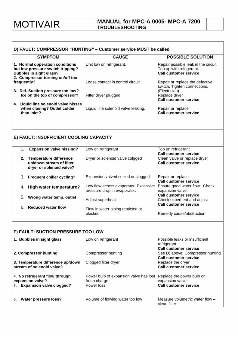
D) FAULT: COMPRESSOR “HUNTING” – Customer service MUST be called
SYMPTOM CAUSE POSSIBLE SOLUTION 1. Normal opperation conditions but low pressure switch tripping? Bubbles in sight glass? 2. Compressor turning on/off too frequently? 3. Ref. Suction pressure too low?
Ice on the top of compressor? 4. Liquid line solenoid valve hisses
when closing? Outlet colder than inlet?
Unit low on refrigerant. Loose contact in control circuit Filter dryer plugged Liquid line solenoid valve leaking.
Repair possible leak in the circuit Top up with refrigerant. Call customer service Repair or replace the defective switch. Tighten connections. (Electrician) Replace dryer Call customer service Repair or replace Call customer service
E) FAULT: INSUFFICIENT COOLING CAPACITY
1. Expansion valve hissing?
2. Temperature difference up/down stream of filter dryer or solenoid valve?
3. Frequent chiller cycling?
4. High water temperature?
5. Wrong water temp. outlet
6. Reduced water flow
Low on refrigerant Dryer or solenoid valve colgged Expansion valved seized or clogged. Low flow across evaporator. Excessive pressure drop in evaporator. Adjust superheat Flow in water piping resticted or blocked
Top un refrigerant Call customer service Clean valve or replace dryer Call customer service Repair or replace Call customer service Ensure good water flow. Check expansion valve. Call customer service Check superheat and adjust Call customer service Remedy cause/obstruction
F) FAULT: SUCTION PRESSURE TOO LOW 1. Bubbles in sight glass 2. Compressor hunting 3. Temperature difference up/down stream of solenoid valve? 4. No refrigerant flow through expansion valve? 5. Expansion valve clogged? 6. Water pressure loss?
Low on refrigerant Compressor hunting Clogged filter dryer Power bulb of expansion valve has lost freon charge. Power loss Volume of flowing water too low
Possible leaks or insufficient refrigerant Call customer service See D) above: Compressor hunting Call customer service Replace the dryer Call customer service Replace the power bulb or expansion valve. Call customer service Measure volumetric water flow – clean filter

MOTIVAIR MANUAL for MPC-A 0005- MPC-A 7200 TROUBLESHOOTING
G) FAULT: CONDENSING PRESSURE TOO HIGH
SYMPTOM CAUSE POSSIBLE SOLUTION 1. Normal opperation; high pressure switch activated?
2. Condenser pressure very
high?
3. Condenser pressure very high?
4. High water temperature?
Too much refrigerant in system Insufficint cooling air to condenser(s). Fans not delivering enough air. Check fan rotation. Check if fan motor has failed. Heat load into water circuit too large.
Possibly overfilled with refrigerant. Check the level. Call customer service. Clean the condenser coil. Check the operating mode of the motor and fans. Change phase order on main power cord or change fan motor. Call customer service. Check cooling load. Call customer service.
H) FAULT: CONDENSING PRESSURE TOO LOW
1. Suction and discharge pressure equalize after pump down?
2. Visable bubbles in sight glass?
High pressure valves broken or leaky. Low on refrigerant
Check the cylinder heads and valves. Call customer service Possible leak or insufficient rerigerant. Call customer service
I) FAULT: AXIAL FANS ! 1. Fan or chiller vibration? 2. No air flow or some fans not
running?
Fan out of balance Fan fuse blown
Inspect the bearings and visually check for damage. Check the voltage. Check the speed regulator (if fitted) and measure the amp. values. Check the motor(s) amp rating(s).
L) FAULT: CHILLED-WATER PUMP
1. Large temperature rise from water out to water in.
2. Water leaking from pump 3. Pump does not run although
cooling is required
Not enough flow through system Pumps seal failure Pump mechanically defective or circuit breaker has tripped
Pressure drop in process cooling circuit is too high. Check the pump pressure gauge. Change pump seal. Call customer service Check pump pressure gauge. External pressure loss may be too high causing high amp draw. Check amp draw of pump.
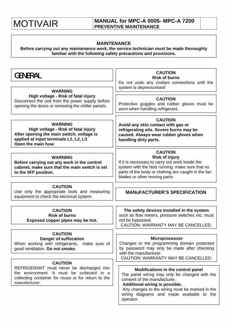
MOTIVAIR MANUAL for MPC-A 0005- MPC-A 7200 PREVENTIVE MAINTENANCE
MAINTENANCE Before carrying out any maintenance work, the service technician must be made thoroughly
familiar with the following safety precautions and provisions.
CAUTION Risk of burns
Do not undo any coolant connections until thesystem is depressurised!
GGEENNEERRAALL
WARNING High voltage - Risk of fatal injury
Disconnect the unit from the power supply beforeopening the doors or removing the chiller panels.
CAUTION Protective goggles and rubber gloves must beworn when handling refrigerant.
CAUTION Avoid any skin contact with gas or refrigerating oiIs. Severe burns may be caused. Always wear rubber gloves when handling dirty parts.
WARNING High voltage - Risk of fatal injury
After opening the main switch, voltage is applied at input terminals L1, L2, L3 Open the main fuse
CAUTION Risk of injury
If it is necessary to carry out work inside the system with the fans running, make sure that no parts of the body or clothing are caught in the fan blades or other moving parts.
WARNING Before carrying out any work in the control cabinet, make sure that the main switch is set to the 0FF position.
CAUTION Use only the appropriate tools and measuringequipment to check the electrical system.
MANuFACTURER’S SPECIFICATION
The safety devices installed in the system such as flow meters, pressure switches etc. mustnot be bypassed. CAUTION: WARRANTY MAY BE CANCELLED.
CAUTION Risk of burns
Exposed copper pipes may be hot.
CAUTION Danger of suffocation
When working with refrigerants, make sure ofgood ventilation. Do not smoke.
Microprocessor Changes to the programming domain protectedby password may only be made after checkingwith the manufacturer. CAUTION: WARRANTY MAY BE CANCELLED.
CAUTION REFRIGERANT must never be discharged intothe environment. It must be coIlected in acollecting container for reuse or for return to themanufacturer.
Modifications in the control panel The panel wiring may only be changed with theconsent of the manufacturer. Additional wiring is possible. Any changes to the wiring must be marked in the
wiring diagrams and made available to theoperator.
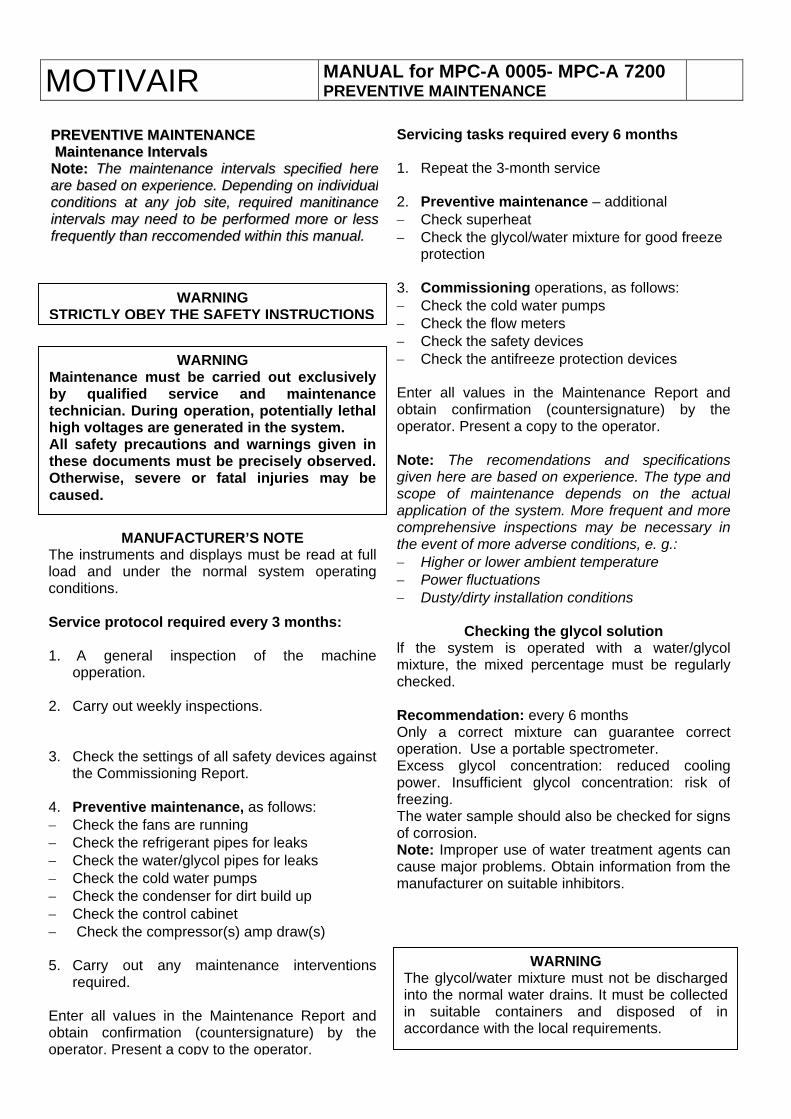
MANUAL for MPC-A 0005- MPC-A 7200 PREVENTIVE MAINTENANCE MOTIVAIR
Servicing tasks required every 6 months 1. Repeat the 3-month service 2. Preventive maintenance – additional − Check superheat − Check the glycol/water mixture for good freeze
protection 3. Commissioning operations, as follows: − Check the cold water pumps − Check the flow meters − Check the safety devices − Check the antifreeze protection devices Enter all values in the Maintenance Report andobtain confirmation (countersignature) by theoperator. Present a copy to the operator. Note: The recomendations and specificationsgiven here are based on experience. The type andscope of maintenance depends on the actualapplication of the system. More frequent and morecomprehensive inspections may be necessary inthe event of more adverse conditions, e. g.: − Higher or lower ambient temperature − Power fluctuations − Dusty/dirty installation conditions
Checking the glycol solution lf the system is operated with a water/glycolmixture, the mixed percentage must be regularlychecked. Recommendation: every 6 months Only a correct mixture can guarantee correctoperation. Use a portable spectrometer. Excess glycol concentration: reduced coolingpower. Insufficient glycol concentration: risk offreezing. The water sample should also be checked for signsof corrosion. Note: Improper use of water treatment agents cancause major problems. Obtain information from themanufacturer on suitable inhibitors.
PPRREEVVEENNTTIIVVEE MMAAIINNTTEENNAANNCCEE MMaaiinntteennaannccee IInntteerrvvaallss NNoottee:: TThhee mmaaiinntteennaannccee iinntteerrvvaallss ssppeecciiffiieedd hheerreeaarree bbaasseedd oonn eexxppeerriieennccee.. DDeeppeennddiinngg oonn iinnddiivviidduuaallccoonnddiittiioonnss aatt aannyy jjoobb ssiittee,, rreeqquuiirreedd mmaanniittiinnaanncceeiinntteerrvvaallss mmaayy nneeeedd ttoo bbee ppeerrffoorrmmeedd mmoorree oorr lleessssffrreeqquueennttllyy tthhaann rreeccccoommeennddeedd wwiitthhiinn tthhiiss mmaannuuaall..
WARNING STRICTLY OBEY THE SAFETY INSTRUCTIONS
WARNING Maintenance must be carried out exclusivelyby qualified service and maintenancetechnician. During operation, potentially lethalhigh voltages are generated in the system. All safety precautions and warnings given inthese documents must be precisely observed.Otherwise, severe or fatal injuries may becaused.
MANUFACTURER’S NOTE The instruments and displays must be read at fullload and under the normal system operatingconditions. Service protocol required every 3 months: 1. A general inspection of the machine
opperation. 2. Carry out weekly inspections. 3. Check the settings of all safety devices against
the Commissioning Report. 4. Preventive maintenance, as follows: − Check the fans are running − Check the refrigerant pipes for leaks − Check the water/glycol pipes for leaks − Check the cold water pumps − Check the condenser for dirt build up − Check the control cabinet − Check the compressor(s) amp draw(s) 5. Carry out any maintenance interventions
required. Enter all vaIues in the Maintenance Report andobtain confirmation (countersignature) by theoperator. Present a copy to the operator.
WARNING The glycol/water mixture must not be dischargedinto the normal water drains. It must be collectedin suitable containers and disposed of inaccordance with the local requirements.
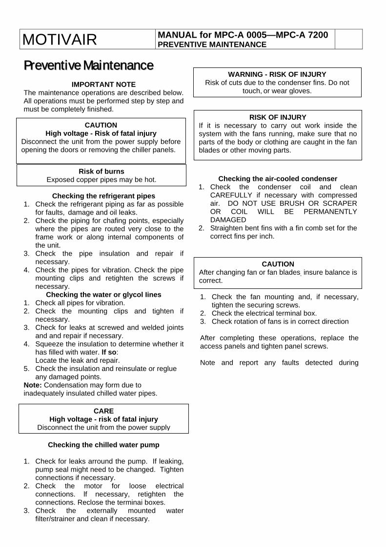
MOTIVAIR MANUAL for MPC-A 0005—MPC-A 7200 PREVENTIVE MAINTENANCE
WARNING - RISK OF INJURY Risk of cuts due to the condenser fins. Do not
touch, or wear gloves.
PPrreevveennttiivvee MMaaiinntteennaannccee IMPORTANT NOTE
The maintenance operations are described below.All operations must be performed step by step andmust be completely finished.
RISK OF INJURY If it is necessary to carry out work inside thesystem with the fans running, make sure that noparts of the body or clothing are caught in the fanblades or other moving parts.
CAUTION High voltage - Risk of fatal injury
Disconnect the unit from the power supply beforeopening the doors or removing the chiller panels.
Risk of burns Exposed copper pipes may be hot. Checking the air-cooled condenser
1. Check the condenser coil and cleanCAREFULLY if necessary with compressedair. DO NOT USE BRUSH OR SCRAPEROR COIL WILL BE PERMANENTLYDAMAGED
2. Straighten bent fins with a fin comb set for thecorrect fins per inch.
Checking the refrigerant pipes 1. Check the refrigerant piping as far as possible
for faults, damage and oil leaks. 2. Check the piping for chafing points, especially
where the pipes are routed very close to theframe work or along internal components ofthe unit.
3. Check the pipe insulation and repair ifnecessary.
4. Check the pipes for vibration. Check the pipemounting clips and retighten the screws ifnecessary.
Checking the water or glycol Iines 1. Check all pipes for vibration. 2. Check the mounting clips and tighten if
necessary. 3. Check for leaks at screwed and welded joints
and and repair if necessary. 4. Squeeze the insulation to determine whether it
has filled with water. lf so: Locate the leak and repair.
5. Check the insulation and reinsulate or reglue any damaged points.
Note: Condensation may form due to inadequately insulated chilled water pipes.
CAUTION After changing fan or fan blades, insure balance iscorrect.
1. Check the fan mounting and, if necessary,tighten the securing screws.
2. Check the electrical terminal box. 3. Check rotation of fans is in correct direction After completing these operations, replace theaccess panels and tighten panel screws. Note and report any faults detected during
CARE High voltage - risk of fatal injury
Disconnect the unit from the power supply
Checking the chilled water pump
1. Check for leaks arround the pump. If leaking,pump seal might need to be changed. Tightenconnections if necessary.
2. Check the motor for loose electricalconnections. lf necessary, retighten theconnections. Reclose the terminai boxes.
3. Check the externally mounted waterfilter/strainer and clean if necessary.
MOTIVAIR MANUAL for MPC-A 0005- MPC-A 7200 Notes on Chlorine free refrigerants
NOTE ON CHLORINE - FREE REFRIGERANTS The compressors designed for operation with chlorine-free refrigerants are factory-filled with ester oils approved by the compressor manufacturer and are marked accordingly. Compared to single-substance refrigerants and azeotropic and quasi-azeotropic mixtures, the zeotropic refrigerant mixtures are characterised by a wider temperature variation. Specific effects on system maintenance and repairs must therefore be taken into account. Due to the fact that zeotropic mixtures can have different compositions in the liquid and gas phases, it is especially important that these refrigerants are only ever charged into the system in the Iiquid state. Therefore: strictly follow the filling instructions of the refrigerant manufacturer. In the event of a Ieak, the change in mixture composition Ieads to reduced superheat after the thermostatic expansion valve and ultimately to liquid hammering in the compressor. Another aspect of the mixture change is sudden ‘hunting’ of the expansion valve. Tests by refrigerant manufacturers and the past experience of users have shown that this situation can be stabilized by recovering the complete charge and re-filling the system. Before replacing the entire circulating refrigerant, a mixture concentration analysis is recommended.
The use of polyester oils ("POE"s) is necessary for operation with chlorine-free refrigerants. Compared to minerai oils, POEs have high hygroscopicity (moisture absorption). If POE is exposed for only a short time to the ambient air, it absorbs so much moisture that it is no longer acceptable for use in refrigeration circuits. Since a POE binds moisture more firmly than mineral oil, the moisture is more difficult to remove from the system by vacuum. Consequently, we recommend filling the system with a POE containing Iess than 50ppm moisture particles.With the use of appropriately sized filter dryers, the moisture content in the system can be kept below 50 ppm. lf the moisture level rises to unacceptable Ievels, corrosion and copper-plating can occur. By perfect evacuation, the residual moisture can be reduced to 10 ppm. The system must be evacuated to 0.3 mbar. In the event of any doubt regarding the moisture level in the system, an oil sample should be taken and analysed for water content. The installed indicator sight glass can be used for the new refrigerants and oils, but they do not show the actual moisture content, which may be higher than shown in the sight glass due to the high hygroscopicity. The display in the sight glass only gives the moisture content of the refrigerant. To determine the real moisture level, an oil sample must be taken from the system and analyzed.
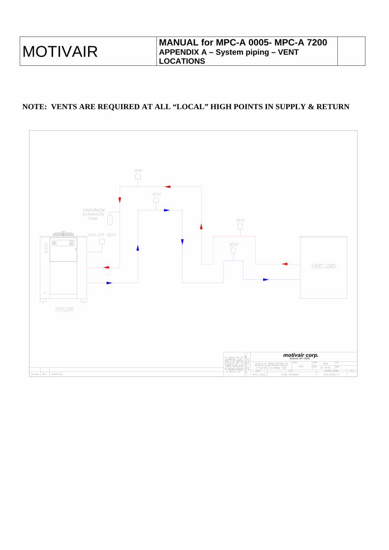
MANUAL for MPC-A 0005- MPC-A 7200 APPENDIX A – System piping – VENT LOCATIONS
MOTIVAIR NOTE: VENTS ARE REQUIRED AT ALL “LOCAL” HIGH POINTS IN SUPPLY & RETURN
MANUAL for MPC-A 0005- MPC-A 7200 MOTIVAIR Piping Recomendations
PPIIPPIINNGG IINNSSTTAALLLLAATTIIOONN
This section is intended as a guide for the correct installation of the chilled water piping system, including this chiller. However, the chiller manufacturer accepts no responsibility whatsoever for the installation of the chiller or the associated piping. All piping must be installed only by a licensed plumbing contractor, and in compliance with local codes. DO NOT USE GALVANIZED PIPING IF GLYCOL IS TO BE USED IN THE CHIILED WATER SYSTEM. Chemical reaction between the glycol and the galvanized piping (galvanic action) can be detrimental to the cooling system, the glycol and the chiller. Piping material may be copper, plastic, carbon or stainless steel, depending on the requirements of each installation. It is the responsibility of the engineer and/or the piping contractor to insure that the piping is correctly sized in relation to the installation, and the available dynamic head of the pump installed inside the chiller. The chilled water pipe connections on the chiller are not necessarily the appropriate size for the system piping. As a general guide, the chiller pipe connections should be considered as the minimum pipe size required for the installation. Drastic reductions in pipe sizing (small hoses, etc.) will reduce the chilled water flow and may cause a low flow alarm, or freezing damage in the evaporator. Note: installations with low water flow/high water temperature rise should always have a full-ported by-pass installed between the chiller inlet and outlet connections, with a manually adjustable gate valve in the by-pass line. Correctly adjusted, this blended return water will maintain an adequate flow through the chiller, at an acceptable return temperature. Always install a pressure gauge in the return piping close to the chiller. This is essential for monitoring system pressure and pump performance. It is good piping practice, especially on systems with short piping runs and/or low system pressure loss, to install a gate valve in the DISCHARGE line from the chiller for throttling purposes. This allows the operator to maintain optimum pump performance by adding resistance to the system. NEVER throttle the water flow on the return line to the chiller. This will cause cavitation and over-heating of the pump. AAUUTTOOMMAATTIICC WWAATTEERR MMAAKKEE--UUPP If the chilled water cooling system is expected to lose water during normal operation (mold-changing, etc.) an automatic water make-up system should be installed, or can be supplied as a factory option. The auto make-up system must include a water pressure regulator and pressure gauge. CAUTION: The tank inside the chiller has a maximum pressure rating of 40 PSIG. Do not discharge city water (which can be as high as 60-80 PSIG) directly into the chiller. Instantaneous pressurization can cause the tank to rupture before the pressure relief valve opens. NOTE: Do not use an automatic water make-up system if glycol is installed for anti-freeze protection. The glycol will become diluted and the freeze protection will be lost. Some critical applications require the installation of emergency city water and drain solenoid valves, in the event of a chiller failure. In this case, the chiller MUST be isolated from the city water pressure to avoid damage. After operation of the emergency city water system, the glycol concentration must be carefully checked using a spectrometer. Add glycol to maintain the correct antifreeze concentration if required.
MANUAL for MPC-A 0005- MPC-A 7200
EEXXPPAANNSSIIOONN TTAANNKK There is a small air space provided inside the top of the insulated reservoir of the chiller. This is designed to act as a compression chamber, in order to absorb moderate hydraulic expansion of the water, during operation. For systems with extensive piping, or large system chilled water volumes it is recommended to install a closed diaphragm expansion tank in the return chilled water line, close to the chiller. The tank should be sized using the appropriate calculations for the volume of water in the system, and the maximum expected temperature fluctuation of the water in the piping system, under any conditions. The purpose of the expansion tank is to absorb hydraulic expansion of the water in the system, which can cause damage to the chiller, piping and/or equipment to be cooled. The expansion tank should be connected to the side of a vertical pipe or the bottom of the horizontal return piping so that trapped air circulating in the chilled water does not become trapped in the expansion tank. Expansion tanks are typically factory pre-charged with compressed air to approximately 12-20 psig. After installation, filling & venting of the entire system, the pressure of the expansion tank should be set to provide a pressure of 5-10 PSIG on the return side of the chiller, with the chiller in operation. Air pressure can be added or removed from the diaphragm tank via the Schraeder valve. NOTE: Vertical piping immediately connected to and from the chiller will impose a static (or standing) head pressure, which can be read on the pump discharge gauge of the chiller, and the gauge installed on the return line to the chiller, when the system is not operating. For example, if the supply and/or return piping from the chiller rises 15 feet before running above a ceiling, etc. this will show a gauge static pressure of approximately 6-7 PSIG on the gauges (feet x .424 = PSIG). This is simply the weight of the water in the vertical piping at that location, and does not indicate an overall system pressure. SSYYSSTTEEMM VVEENNTTIINNGG The single most common problem in chiller piping installations is lack of chilled water flow caused by poor piping practices and/or inadequate venting of the system. The symptom is a repeated flow alarm, when the flow switch installed in the return line inside the chiller opens the control circuit, stops the chiller and sets the alarm. This chiller is a CLOSED CIRCUIT system and is not open to atmosphere. This means that air will remain in all local high points of the system when it is initially filled with water. NOTE: A local high point is any point in the piping, which can be described as an inverted “U” section. More clearly defined, if the piping rises vertically ANYWHERE, AND AT ANY ELEVATION IN THE SYSTEM, travels horizontally, then drops again vertically, this inverted “U” section of piping is a permanent air lock AND MUST BE VENTED. Venting is required AT ALL LOCAL HIGH POINTS, and is required on both the supply and return pipes. Vents can be either manual, or automatic. Automatic vents should always be installed with an isolation valve for future service access, repair or replacement. Automatic vents are particularly susceptible to drawing air into the return chilled water piping if this line is allowed to fall into a vacuum.
MOTIVAIR Piping Recomendations MOTIVAIR Piping Recomendations
PPOOSSIITTIIVVEE PPRREESSSSUURRIIZZAATTIIOONN OOFF TTHHEE SSYYSSTTEEMM There are two (2) reasons for positive pressure in a closed loop, pumped piping system:
1. Prevention of air being drawn into the system at vent locations close to the chiller, caused by the pump drawing a vacuum in the return line.
2. Optimizing pump performance by providing a net positive suction head (N.P.S.H.) to the pump.
Positive system pressure can be imposed by carefully & slowly introducing city water pressure, via a hose connection anywhere in the system. After the system has been completely filled & vented, note the gauge pressure at the supply & return of the chiller. If there is no significant vertical piping connected directly to the chiller, the gauges should be at zero. If a pre-pressurized expansion tank is installed in the system, the initial system pressure should be approximately that of the expansion tank. Start the chiller and observe the operating pressure on both the return and discharge water pressure gauges. The return line to the chiller (while operating) should be approximately 5-10 PSIG, confirmed by the return line pressure gauge. The discharge gauge on the chiller should be approximately 30-40 PSIG, depending on the piping and system pressure losses of each installation. The return (or suction) pressure can be raised or lowered by carefully using city water pressure via a hose connection, or by adjusting the diaphragm pressure of the expansion tank, or a combination of both. NOTE: The expansion tank should not normally be pressurized to more than 20 PSIG, measured when the system is not operating. The final discharge pump pressure should NEVER be allowed to exceed the maximum pump rating pressure (normally around 35-50 PSIG). CAUTION: Supercharging the pump with city water pressure higher than the nominal rating of the pump, can damage the mechanical pump seals, or cause damage to the chiller, piping system or customer equipment. This damage is not covered by the chiller warranty. WATER/GLYCOL FILLING If glycol is required for antifreeze protection, ALWAYS use an industrial inhibited ethylene glycol, or propylene (food-grade) glycol. DO NOT use automobile antifreeze. Suitable glycols are manufactured by the Dow Chemical Company for this purpose, and available nationwide. There are other glycol suppliers available, but always exercise great caution in the selection of a glycol supplier, and always confirm the freeze protection after installation, using a spectrometer. Damage caused by freezing is not covered under warranty. Glycol can be pre-mixed with water to the correct concentration, then pumped into the system, or pumped in separately from the water, provided the system capacity is calculated accurately. The most common method for filling the system is to pump the water/glycol into the fill or drain connection of the chiller, with all system vents open. There is a manual vent located at the back of the chiller for initial filling/venting purposes, in addition to the high point piping vents. NOTE: The system should be filled slowly and carefully, allowing all the air to escape. The system can only be filled as fast as the air can escape. Be patient, and do not over-pressurize the system. After initial operation, check all air is vented from the system.
CCAAUUTTIIOONN:: A FILTER/STRAINER MUST BE INSTALLED ON THE INLET TO THE CHILLER, IN ORDER TO PREVENT PARTICULATES (RUST, DIRT, INSTALLATION DEBRIS) FROM BLOCKING THE EVAPORATOR. Blockage will severely impair chiller performance and is NOT covered by warranty.