Embed Size (px)
Citation preview
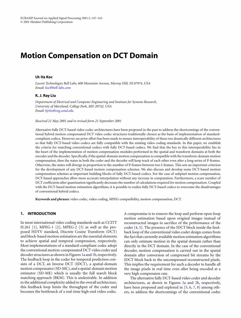
EURASIP Journal on Applied Signal Processing 2001:3, 147–162© 2001 Hindawi Publishing Corporation
Motion Compensation on DCT Domain
Ut-Va Koc
Lucent Technologies Bell Labs, 600 Mountain Avenue, Murray Hill, NJ 07974, USAEmail: [email protected]
K. J. Ray Liu
Department of Electrical and Computer Engineering and Institute for Systems Research,University of Maryland, College Park, MD 20742, USAEmail: [email protected]
Received 21 May 2001 and in revised form 21 September 2001
Alternative fully DCT-based video codec architectures have been proposed in the past to address the shortcomings of the conven-tional hybrid motion compensated DCT video codec structures traditionally chosen as the basis of implementation of standard-compliant codecs. However, no prior effort has been made to ensure interoperability of these two drastically different architecturesso that fully DCT-based video codecs are fully compatible with the existing video coding standards. In this paper, we establishthe criteria for matching conventional codecs with fully DCT-based codecs. We find that the key to this interoperability lies inthe heart of the implementation of motion compensation modules performed in the spatial and transform domains at both theencoder and the decoder. Specifically, if the spatial-domain motion compensation is compatible with the transform-domain motioncompensation, then the states in both the coder and the decoder will keep track of each other even after a long series of P-frames.Otherwise, the states will diverge in proportion to the number of P-frames between two I-frames. This sets an important criterionfor the development of any DCT-based motion compensation schemes. We also discuss and develop some DCT-based motioncompensation schemes as important building blocks of fully DCT-based codecs. For the case of subpixel motion compensation,DCT-based approaches allow more accurate interpolation without any increase in computation. Furthermore, a scare number ofDCT coefficients after quantization significantly decreases the number of calculations required for motion compensation. Coupledwith the DCT-based motion estimation algorithms, it is possible to realize fully DCT-based codecs to overcome the disadvantagesof conventional hybrid codecs.
Keywords and phrases: video codec, video coding, MPEG compatibility, motion compensation, DCT.
1. INTRODUCTION
In most international video coding standards such as CCITTH.261 [1], MPEG-1 [2], MPEG-2 [3] as well as the pro-posed HDTV standard, Discrete Cosine Transform (DCT)and block-based motion estimation are the essential elementsto achieve spatial and temporal compression, respectively.Most implementations of a standard-compliant codec adoptthe conventional motion-compensated DCT video coder anddecoder structures as shown in Figures 1a and 1b, respectively.The feedback loop in the coder for temporal prediction con-sists of a DCT, an Inverse DCT (IDCT), a spatial-domainmotion compensator (SD-MC),and a spatial-domain motionestimator (SD-ME) which is usually the full search blockmatching approach (BKM). This is undesirable. In additionto the additional complexity added to the overall architecture,this feedback loop limits the throughput of the coder andbecomes the bottleneck of a real-time high-end video codec.
A compromise is to remove the loop and perform open-loopmotion estimation based upon original images instead ofreconstructed images in sacrifice of the performance of thecoder [4, 5]. The presence of the IDCT block inside the feed-back loop of the conventional video coder design comes fromthe fact that currently available motion estimation algorithmscan only estimate motion in the spatial domain rather thandirectly in the DCT domain. In the case of the conventionaldecoder, motion compensation is carried out in the spatialdomain after conversion of compressed bit streams by theIDCT block back to the uncompressed reconstructed pixels.This implies the requirement for such a decoder to handle allthe image pixels in real time even after being encoded at avery high compression rate.
The alternative fully DCT-based video coder and decoderarchitectures, as shown in Figures 2a and 2b, respectively,have been proposed and explored in [5, 6, 7, 8] among oth-ers, to address the shortcomings of the conventional codec

148 EURASIP Journal on Applied Signal Processing
+ DCT Q
Q−1
VLC
IDCT
SD-ME
+video in channel
+
−
(a) Conventional hybrid motion-compensated DCT video coder.
VLD Q IDCT +
SD-MC
−1
(b) Conventional hybrid motion-compensated DCT video decoder.
Figure 1: Conventional hybrid motion-compensated DCT videocodec: motion estimation/compensation are performed in the spa-tial domain.
structures. In the fully DCT-based video codec, motion es-timation and compensation are performed on the com-pressed bit stream in the transform (DCT) domain, and thusthese functional blocks are called transform-domain motionestimator (TD-ME) and transform-domain motion compen-sator (TD-ME), respectively, to be distinguished from theirspatial-domain counterparts. The resultant fully DCT-basedmotion compensated video codec structure enjoys severaladvantages over the conventional hybrid motion compen-sated DCT video codec structure:
• Less coder components and complexity: removal of theDCT-IDCT pair in the feedback loop of the fully DCT-basedreduces the total number of components required in the feed-back loop and thus the complexity of the complete coder.
• Higher throughput rate: the feedback loop of a videocoder requires processing at the frame rate so that the pre-vious frame data can be stored in the frame memory andneed to be available for coding the next incoming frame.Traditionally, this loop has four components plus the spatial-domain motion estimation and compensation unit and thuscreates the bottleneck for encoding large frame sizes in realtime. In the conventional coder, the whole frame must beprocessed by both the DCT-IDCT pair and the Q-Q−1 pairbefore the next incoming frame. In the DCT-based struc-ture, the whole frame must be processed by only the Q-Q−1 pair. This results in a less stringent requirement on theprocessing speed of the feedback loop components. Alterna-tively, this may increase the throughput rate of the coder andthus allow processing larger frame sizes when the technol-ogy keeps on improving the processing speed of these com-ponents. This high throughput advantage becomes increas-ingly important when the advances in optical networking
DCT Q
Q
VLC+
video in channel
+
+
TD-ME
−1
−
(a) Fully DCT-based motion-compensated video coder.
+ IDCTVLD Q
TD-MC
−1
(b) Fully DCT-based motion-compensated video decoder.
Figure 2: Fully DCT-based motion-compensated video codec:motion estimation/compensation are completed in the transform(DCT) domain.
technology permit transmission of high-quality production-grade video signals over broadband networks in real time ataffordable costs.
•Lower computational complexity of DCT-based motionestimation and compensation approaches: due to the decor-relation of DCT exploited in most video standards, mostenergy tend to cluster in a few DCT coefficients, especiallythe DC terms, with the rest being zeros after quantization.This characteristic is particularly beneficial to the DCT-basedapproach since no computation is needed for the majority ofDCT coefficients being zero [9].
• Joint optimization of DCT-based components: a fastlattice-structured DCT coder generates dual outputs (DCTand DST) which can be utilized by the DCT-based motionestimation algorithms.
• Extendibility to a transcoder structure: an optimaltranscoder modifies the encoded video bit stream in the DCTdomain directly to fit different usage requirements (such asframe rate conversion, frame size conversion, bit rate con-version, etc.) different from the usage requirement originallyplanned for. The fully DCT-based structure handles videodata completely in the DCT domain and therefore can be eas-ily extended to provide a transcoder function by cascading aDCT-based decoder with certain simplification and modifi-cation required by the end usage. For example, the DCT coderat the front of a DCT-based coder and an IDCT decoder of aDCT-based decoder can be removed.
• Additional information processing: DCT coefficientscarry certain information which can be utilized, as an exam-ple, for image segmentation in the DCT domain [10]. TheDCT-based codec structure facilitates such use of DCT coef-ficients.

Motion compensation on DCT domain 149
• Compatibility with existing standards: one of themain objectives of most motion-compensated DCT videocompression standards is to ensure proper interoperabilitybetween an encoder and a decoder supplied by two dif-ferent vendors. The fully DCT-based structure encodes theintraframes and motion compensated residuals in DCT fun-damentally in the same way as the hybrid structure does. Theencoded bit stream can be made fully compatible with theexisting video coding standards under certain conditions asdiscussed later in this paper.
For compatibility with existing standards, a decoder mustbe able to track closely the state of the encoder transmittingthe encoded bit stream to ensure interoperability, because ofthe recursive nature of the motion-compensated standards,especially for systems having lots of interframes to achievehigh compression. In this way, the decoder will be able toreproduce the images in as high fidelity as possible. However,despite the above advantages of fully DCT-based codecs, noeffort has been spent on the important issue of how the con-ventional hybrid codecs and the fully DCT-based codecs canmatch with each other without causing degradation in videoquality. In Section 2, we will demonstrate that
• The fully DCT-based codecs and the conventionalhybrid codecs are mathematically compatible in the sense thatthe state of a DCT-based decoder can track the DCT-basedencoder state in the same manner as the hybrid counterparts.
• If the coder-encoder pair of different architectural typesmeets the matching condition, then we can mix differenttypes of coders and decoders without having the decodersreaching divergent states after a long series of P-frames.
Furthermore, we will also discuss DCT-based motioncompensation schemes employed in these fully DCT-basedcodecs in Section 3.
2. MATCHING FULLY DCT-BASED CODECS WITHCONVENTIONAL HYBRID CODECS
In order to gain insight into the main differences betweenthe conventional codec and the fully DCT-based one, we aregoing to derive the mathematical formulation for both ar-chitectures. The conventional hybrid coder is redrawn inFigure 3 with the SD-ME block splitted into two functionalblocks (ME for motion estimation and MC for motion com-pensation) and the frame memory (Z) explicitly depicted forthe storage of the previous reconstructed frame. The esti-mated motion vector field vt for the current frame is es-timated from both the current frame xt and the previousreconstructed frame yt−1. The encoded bit stream for thecompressed interframe residual is denoted as VLC{st} whereVLC{·} is the variable length coder and st is the quantizedDCT coefficients of the interframe motion-compensatedresidual. Therefore, the conventional hybrid coder (also calledSpatial Domain Encoder or SE for short) can be describedmathematically as an iterative function:
• Interframe encoding (P-frame) for SE:
st = Q{DCT
{xt −MC
(yt−1, vt
)}},
yt = MC(yt−1, vt
)+ IDCT{Q−1{st}}, (1)
+
+
Q
Q−1
VLCxtst
DCT
IDCT
Z
rt
ht
ytyt−1
vt
MC
MEZ = Frame memory
−
ˆ
Figure 3: Modeling diagram for conventional hybrid motion-compensated DCT video coder.
+
+
DCT−
Q
Q−1
VLC
ZMCD
MED
xtrDt
yt−1
htD
ytD
stD
D
Z = Frame memoryvtDˆ
Figure 4: Modeling diagram for fully DCT-based motion-compensated video coder.
whereyt is the state of the coder stored in the frame memory,and the estimated motion vector
vt = ME(yt−1, xt
). (2)
• Intraframe encoding (I-frame) for SE:
s0 = Q{DCT
{x0}},
y0 = h0 = IDCT{Q−1{Q{DCT
{x0}}}}
.(3)
The above formulation considers only a group of pictureswith the frame x0 encoded as an I-frame and the rest offrames xt as P-frames. Without loss of generality, B-framesare not considered here. Then st and vt are entropy codedinto the bit stream sent to a decoder.
The fully DCT-based coder structure is redrawn inFigure 4 where the TD-ME block is also splitted, explicitlyfor formulating the encoding process, into two sections: themotion estimation (MED) and the motion compensation(MCD). Note that the superscript D in Figure 4 and equa-tions (4), (5), and (6) below are used to distinguish the fullyDCT-based structure (called Transform Domain Encoder orTE) from the SE. Similar to the formulation of the SE, we con-sider only one group of pictures with the first frame coded asan I-frame and the rest as P-frames. The recursive functiondescribing the TE structure is listed as follows:

150 EURASIP Journal on Applied Signal Processing
VLD Q−1 IDCT
zt−1
st
MC
wt
Z
+
vt
x= t
ˆ
zt
Figure 5: Modeling diagram for conventional hybrid motion-compensated DCT video decoder.
+VLD Q IDCTwtD
stD
t−1zD
ZMCD
vtD
txD−1ˆ
ˆ
tzD
Figure 6: Modeling diagram for fully DCT-based motion-compensated video decoder.
• Interframe encoding (P-frame) for TE:
sDt = Q{DCT
{xt}−MCD
(yDt−1, v
Dt)},
yDt = MCD(yDt−1, v
Dt)+Q−1{sDt }, (4)
where sDt is the quantized DCT coefficients of the interframemotion-compensated residual, yDt−1 is the state of the coderstored in the frame memory, and the estimated motion vector
vDt = MED(yDt−1,DCT
{xt}). (5)
• Intraframe encoding (I-frame) for TE:
sD0 = Q{DCT
{x0}},
yD0 = hD0 = Q−1{Q{DCT{x0}}}.
(6)
In most motion-compensated video compression stan-dards, the conventional hybrid decoder (Spatial DomainDecoder or SD for short) is usually cited for its concep-tual simplicity. The SD is also depicted in Figure 5 wherest reappears at the output of VLD (Variable Length Decoder)because variable length coding is considered as a reversibleprocess, that is, VLD{VLC{α}} = α. The formulation for theSD is listed as follows:
• Interframe decoding (P-frame) for SD:
xt = IDCT{Q−1{st}}+MC
(xt−1, vt
),
zt = xt,(7)
where xt is the reconstructed frame image at the decoderand zt will be stored in the frame memory as the state of thedecoder.
• Intraframe decoding (I-frame) for SD:
z0 = x0 = w0 = IDCT{Q−1{s0}}, (8)
where s0 = Q{DCT{x0}}.Based on the DCT-based motion compensation schemes
discussed above, the Transform Domain Decoder (TD), afully DCT-based decoder, can be constructed [8, 11] as shownin Figure 6 with all the signals and components explicitlylabeled. The TD can be modeled as follows:
• Interframe decoding (P-frame) for TD:
xDt = IDCT{Q−1{sDt }+MCD
(zDt−1, v
Dt)},
zDt = MCD(zDt−1, v
Dt)+Q−1{sDt },
(9)
where xDt is the reconstructed frame image at the decoderand zDt will be stored in the frame memory as the state of thedecoder.
• Intraframe decoding (I-frame) for TD:
xD0 = IDCT{wD
0
} = IDCT{Q−1{sD0 }},
zD0 = wD0 = Q−1{sD0 },
(10)
where sD0 = Q{DCT{x0}}.No matter how we match the spatial- or transform-
domain encoders (SE or TE) with the spatial- or transform-domain decoders (SD or TD), the reconstructed intraframes(t = 0) are related to the original frames as follows:
x0 = IDCT{Q−1{Q{DCT
{x0}}}}
. (11)
However, for intraframes, the reconstructed frames will havesubtle difference with different matching pairs. As discussedbelow, the subtle difference in the states of the encoder andthe decoder may have a divergent effect on the reconstructedimages after encoding a long series of P-frames.
2.1. Matching SE with SD
If we send the encoded bit stream from an SE to an SD, thenwe can show that, as long as the encoder-decoder pair havematching DCT/IDCT, Q/Q−1 and MC implementation,
wt = ht, zt = yt, (12)
where zt (= xt) and yt are the decoder and encoder states,respectively. In other words, the decoder can always trackthe state of the encoder even after a long series of P-frames.However, in practice, it is difficult to implement matchingcomponents at both the encoder and the decoder. As a result,a new intraframe is usually sent after a limited number ofP-frames to reset the state of the codecs before diverging toofar off. The reconstructed frames can be shown to be relatedto the original images as below:
xt = IDCT{Q−1{Q{DCT
{xt −MC
(xt−1, vt
)}}}}+MC
(xt−1, vt
).
(13)

Motion compensation on DCT domain 151
2.2. Matching TE with TD
Similarly, if we send the encoded bit stream from a TE to aTD, then we can prove that, as long as the encoder-decoderpair have matching DCT/IDCT, Q/Q−1 and MCD implemen-tation,
wDt = hDt , zDt = yDt , (14)
where zDt and yDt are the decoder and encoder states, respec-tively. Therefore, the decoder can always track the state of theencoder even after a long series of P-frames in the same way asthe SE-SD pair. It should be noted that, unlike the states of theSE-SD pair being the reconstructed frame images, the statesof this TE-TD pair are the quantized DCT coefficients usuallyhaving many zeros in the high-frequency DCT domain andthus requiring less storage space than the SE-SD pair.
The reconstructed frames are related to the originalimages as below:
xDt = IDCT{zDt}, (15)
where
zDt = Q−1{Q{DCT{xt}−MCD
(zDt−1, v
Dt)}}
+MCD(zDt−1, v
Dt).
(16)
2.3. Matching TE with SD
When the encoded bit stream from an SE is decoded by a TD,that is,
st = sDt , vt = vDt , (17)
it can be shown that
wt = IDCT{hDt}. (18)
The reconstructed frames are related to the original imagesas below:
xt = IDCT{Q−1{Q{DCT
{xt}−MCD
(yDt−1, vt
)}}}+MC
(xt−1, vt
).
(19)
However, the contents of the frame memories (zt and yDt )of the TE encoder and the SD decoder are quite differ-ent: the frame memory of the TE holds the quantized DCTcoefficients of the reconstructed frames whereas the SD framememory stores the reconstructed images. Now we need toshow the following theorem.
Theorem 1. If the SD decoder and the TE encoder satisfy thematching MC-MCD condition as described as follows:
MC(IDCT
{yDt−1
}, vDt
) = IDCT{MCD
(yDt−1, v
Dt)},
IDCT{a+ b} = IDCT{a} + IDCT{b},(20)
then both frame memory contents can maintain a fixed rela-tionship in order for the SD decoder to track the state of theTE encoder for accurately decoding a long series of P-frames in
high-fidelity, that is,
zt = IDCT{yDt}. (21)
Proof. For intraframes (t = 0),
z0 = IDCT{Q−1{Q{DCT
{x0}}}}
= IDCT{hD0} = IDCT
{yD0}.
(22)
For t = 1, z1 = IDCT{Q−1{sD1 }} +MC(z0, vD1 ), and
IDCT{yD1} = IDCT
{Q−1{sD1 }+MCD
(yD0 , v
D1
)}= IDCT
{Q−1{sD1 }}+ IDCT
{MCD
(yD0 , v
D1
)}= z1 +
[IDCT
{MCD
(yD0 , v
D1
)}−MC(z0, vD1
)]= z1
(23)
if IDCT{MCD(yD0 , vD1 )} = MC(IDCT{yD0 }, vD1 ). The first
equality holds for the distributive property of IDCT.Now assuming that zt = IDCT{yDt },
IDCT{yDt+1
}= IDCT{Q−1{sDt+1
}+MCD(yDt , v
Dt+1
)}= IDCT
{Q−1{sDt+1
}}+ IDCT{MCD
(yDt , v
Dt+1
)}=zt+1+
[IDCT
{MCD
(yDt , v
Dt+1
)}−MC(zt, vDt+1
)]= zt+1
(24)
if IDCT{MCD(yDt , vDt+1)} = MC(IDCT{yDt }, vDt+1).
The first requirement is the matching condition ofMC-MCD simply stating that the conventional motion com-pensated frame (MC) must be the same as the IDCT (image)of the DCT-based motion compensated frame (MCD). Thesecond condition says that the distributive property of IDCTmust also be maintained true even in the finite-length andfixed-point implementation though it holds in theory.
When the first requirement cannot be satisfied, we findthat the encoder and the decoder may have progressivelydivergent states as more P-frames are inserted between twoI-frames. We may define the difference between the encoderand decoder states as δt for the tth P-frame as follows:
δt � IDCT{yDt}− zt. (25)
In other words, δt is defined as the encoder state minus thedecoder state. We further assume that the second conditionholds and the spatial-domain and transform-domain motioncompensators produce results differing by a fixed amount ∆for each pixel for the sake of simplicity in the analysis
IDCT{MCD(a,v)
}−MC(DCT{a}, v) = ∆. (26)
We know that δ0 = IDCT{yD0 } − z0 = 0. Also
δ1 = IDCT{yD1}− z1
= IDCT{MCD
(yD0 , v
D1
)}−MC(IDCT
{yD0}, vD1
)= ∆.
(27)

152 EURASIP Journal on Applied Signal Processing
Similarly,
δ2 = IDCT{MCD
(yD1 , v
D2
)}−MC(z1, vD2
)= IDCT
{MCD
(yD1 , v
D2
)}−MC(IDCT
{yD1}+ δ1, vD2
).
(28)
Usually the commonly used spatial-domain motion compen-sation algorithms are distributive:
MC(a+ b,v) = MC(a,v)+MC(b, v). (29)
Since ∆ is assumed to be fixed independent of its pixel posi-tion,
δ2 = IDCT{MCD
(yD1 , v
D2
)}−MC(IDCT
{yD1}, vD2
)+MC
(δ1, vD2
)= ∆+∆ = 2∆.
(30)
In general,
δt = IDCT{MCD
(yDt−1, v
Dt)}−MC
(zt−1, vDt
)= ∆+ (t − 1)∆ = t∆. (31)
This suggests that the state difference will diverge in propor-tion to the number of P-frames between two I-frames. If ∆ ispositive, then the decoded picture will become dimmer anddimmer; otherwise, the decoded picture will become brighterand brighter.
2.4. Matching SE with TD
A number of papers (see [8, 11, 12]) discuss the implementa-tion of a DCT-based decoder taking an SE-encoded bit streambut none of them has addressed the issue of divergent statesif their DCT-based decoder is not matched properly with theconventional hybrid encoder.
Consider the case when the encoded bit stream from anSE is decoded by a TD, that is,
sDt = st, vDt = vt . (32)
We can show that
ht = IDCT{wDt}. (33)
The reconstructed frames are constructed from the originalimages accordingly:
xDt = IDCT{Q−1{Q{DCT
{xt −MC
(yt−1, vt
)}}}+MCD
(zDt−1, v
Dt)}.
(34)
In the same way as in the case of the TE-SD pair, we aregoing to show the following theorem.
Theorem 2. If the TD decoder and the SE encoder satisfy thematching MC-MCD condition as described in the following:
MC(IDCT
{zDt−1
}, vt) = IDCT
{MCD
(zDt−1, vt
)},
IDCT{a+ b} = IDCT{a} + IDCT{b}, (35)
then both frame memory contents can maintain a fixed rela-tionship in order for the TD decoder to track the state of the SEencoder and accurately decode P-frames continuously in high-fidelity:
yt = IDCT{zDt}. (36)
Proof. For intraframes (t = 0), y0 = IDCT{Q−1{Q{DCT{x0}}}} = x0 = IDCT{zD0 }. For t = 1, y1 = h1 +MC(IDCT{zD0 }, v1), and
IDCT{zD1} = IDCT
{wD
1 +MCD(zD0 , v1
)}= IDCT
{wD
1
}+ IDCT{MCD
(zD0 , v1
)}= y1 +
[IDCT
{MCD
(zD0 , v1
)}−MC(y0, v1
)]= y1
(37)
if IDCT{MCD(zD0 , v1)} = MC(IDCT{zD0 }, v1).Now assuming that yt = IDCT{zDt },
IDCT{zDt+1
}= IDCT{wDt+1 +MCD
(zDt , vt+1
)}= IDCT
{wDt+1
}+ IDCT{MCD
(zDt , vt+1
)}=yt+1+
[IDCT
{MCD
(zDt , vt+1
)}−MC(yt, vt+1
)]= yt+1
(38)
if IDCT{MCD(zDt , vt+1)} = MC(IDCT{zDt }, vt+1).
Notice that the first requirement of a matching MC-MCD
pair is the same as the matching condition for the TE-SDpair. This implies that if we can build a matching MC-MCD
pair satisfying the first requirement, then we can build a TEand TD so that we can mix the encoder-decoder pair in anycombination without reaching the divergent states.
Similar to the case of matching TE with SD, we can derivehow much the decoder state diverges from the encoder statein terms of the number of P-frames between two I-frames, ifthe first condition cannot be met. Define the state difference,δ′t for the tth P-frame as follows:
δ′t � −(yt − IDCT{zDt}). (39)
Please note that δ′t is defined as the decoder state minus theencoder state, opposite to δt in the case of matching TE-SD. Similarly, we assume that the second condition holdsand the spatial-domain and transform-domain motion com-pensators produce results differing by a fixed amount ∆ foreach pixel for the sake of simplicity in the analysis as in theTE-SD case:
IDCT{MCD(a,v)
}−MC(DCT{a}, v) = ∆. (40)
Therefore, δ′0 = IDCT{zD0 } −y0 = 0. Also
δ′1 = IDCT{zD1}−y1
= IDCT{MCD
(zD0 , v1
)}−MC(IDCT
{zD0}, v1
)= ∆.
(41)

Motion compensation on DCT domain 153
The equality δ′ = δ = ∆ means that we can expect the samedivergent amount in the codec states for the SE-TD case asfor the TE-SD case. Similarly,
δ′2 = IDCT{MCD
(zD1 , v2
)}−MC(y1, v2
)= IDCT
{MCD
(zD1 , v2
)}−MC(IDCT
{zD1}−∆, v2
).
(42)
Because of the distributive property of spatial-domainmotion compensation (MC(a+b,v)=MC(a,v)+MC(b, v)),and the assumption of ∆ being fixed independent of its pixelposition,
δ′2= IDCT{MCD
(zD1 , v2
)}−MC(IDCT
{zD1}, v2
)+MC(∆, v2
)= ∆+∆ = 2∆.
(43)
In general,
δ′t = IDCT{MCD
(zDt−1, vt
)}−MC(yt−1, vt
)= ∆+ (t − 1)∆ = t∆. (44)
This suggests that the state difference will diverge in propor-tion to the number of P-frames between two I-frames in theopposite direction to the diverging state difference for the caseof matching TE with SD. If ∆ is positive, then the decodedpicture will become brighter and brighter.
2.5. Simulation results
We implement two types of encoders (SE and TE) and twotypes of decoders (SD and TD). In order to make fair com-parison, we use the full search block matching approach forboth encoders to find the estimate of motion vectors. Fur-thermore, in order to verify (31) and (44), we deliberately adda constant∆ to the transform-domain motion compensationprocess so that the motion-compensated frames from boththe spatial-domain and transform-domain motion compen-sators differ by that constant ∆. Simulation is performed onthe “Flower Garden” sequence. The simulation results for thecases of matching TE-SD and SE-TD are plotted in Figures7 and 8, respectively. Both figures show that the codec statedifferences for both cases grow linearly with respect to thenumber of P-frames as predicted by (31) and (44). For thecase of TE-TD, the TD decoder can keep track of the TEencoder state, as shown in Figure 9.
3. DCT-BASED MOTION COMPENSATION SCHEMES
Manipulation of compressed video data in DCT domainhas been recognized as an important component in manyadvanced video applications (cf. [8, 11, 13, 14, 15, 16, 17]). Ina video bridge where multiple sources of compressed videoare combined and retransmitted in a network, techniques ofmanipulation and composition of compressed video streamsentirely in DCT domain eliminate the need to build a decod-ing/encoding pair. Furthermore, manipulation in DCT do-main provides flexibility to match heterogeneous Quality ofService requirements with different network or user resources
0 10 20 30 40 50 60 70 80 90 1000
5
10
15
20
25
30
35
40
45
50
Frame number
En
code
r st
ate-
deco
der
stat
e
∆ = 0.5 (slope = 0.500000)
Figure 7: Simulation result of the “Flower Garden” sequence formatching TE-SD with ∆ = 0.5.
0 10 20 30 40 50 60 70 80 90 100−50
−45
−40
−35
−30
−25
20
15
−10
−5
0
Frame number
En
code
r st
ate
dec
oder
sta
te-
∆ = 0.5 (slope = −0.500000)
−
−
Figure 8: Simulation result of the “Flower Garden” sequence formatching SE-TD with ∆ = 0.5.
such as prioritization of signal components from low orderDCT coefficients to fit low-end communication resources.Finally, many manipulation functions can be performed inthe DCT domain more efficiently than in the spatial domain[14] due to a much lower data rate and removal of the decod-ing/encoding pair. However, all the earlier works have beenfocused mainly on manipulation at the decoder side.
To serve the purpose of building a fully DCT-basedmotion compensated video coder, our aim is to develop thetechniques of motion compensation in the DCT domainwithout converting back to the spatial domain before motioncompensation. In [14], the method of pixelwise (integer-pel)translation in the DCT domain is proposed for extractinga DCT block out of four neighboring DCT blocks at anarbitrary position. Though addressing a different scenario,this method can be applied after modification to integer-pel

154 EURASIP Journal on Applied Signal Processing
0 10 20 30 40 50 60 70 80 90 100−1
0
0.2
0.4
0.6
0.8
1
Frame number
En
code
r st
ate-
deco
der
stat
e
∆ = 0.5 (slope = 0.000000)
−0.8
−0.6
−0.4
−0.2
Figure 9: Simulation result of the “Flower Garden” sequence formatching TE-TD with ∆ = 0.5.
motion compensation in the DCT domain. For subpelmotion compensation, we derive an equivalent form of bi-linear interpolation in the DCT domain and then show thatit is possible to perform other interpolation functions forachieving more accurate and visually better approximationin the DCT domain without increasing the complexity.
3.1. Integer-pel DCT-based motion compensation
As illustrated in Figure 10a, after motion estimation, the cur-rent block C of size N × N in the current frame It can bebest predicted from the block displaced from the currentblock position by the estimated motion vector (du,dv) inthe spatial domain. This motion estimate determines whichfour contiguous predefined DCT blocks are chosen for theprediction of the current block out of eight surroundingDCT blocks and the block at the current block position. Toextract the displaced DCT block in the DCT domain, a directmethod is used to obtain separately from these four contigu-ous blocks four subblocks which can be combined togetherto form the final displaced DCT block as shown in Figure 10bwith the upper-left, lower-left, upper-right, and lower-rightblocks from the previous frame It−1 labeled as B1, B2, B3,and B4, respectively [14]. Subblocks Si are extracted in thespatial domain from these four blocks by pre-multiplicationand post-multiplication of the windowing/shifting matrices,Hi and Vi:
Sk = HkBkVk, for k = 1, . . . ,4, (45)
where Hk and Vk are the N ×N windowing/shifting matricesdefined as
H1 =[
0 Ih1
0 0
], V1 =
[0 0
Iv1 0
],
H2 =[
0 0Ih2 0
], V2 =
[0 0
Iv2 0
],
H3 =[
0 Ih3
0 0
], V3 =
[0 Iv3
0 0
],
H4 =[
0 0Ih4 0
], V4 =
[0 Iv4
0 0
]. (46)
Here In is the n × n identity matrix, that is, In =diag {1, . . . ,1} and n is determined by the height/width ofthe corresponding subblock. These pre-multiplication andpost-multiplication matrix operations can be visualized inFigure 10c where the overlapped grey areas represent theextracted subblock. Then these four subblocks are summedto form the desired translated block Bref .
If we define the DCT operation on an N ×N matrix B as
DCT{B} = DBDT , (47)
where the (k,m) element of D is the DCT-II kernel:
D(k,m)= 2NC(k)cos
kπN
(m+ 1
2
), for k,m=0, . . . , N−1.
(48)Therefore, DTD = (2/N)IN . The formation of the DCT ofBref in the DCT domain can be described in this equation:
DCT{Bref
} = (N2
)2 4∑k=1
DCT{Hk}DCT
{Bk}DCT
{Vk}. (49)
This corresponds to pre- and post-multiplication of the DCTtransformed Hk and Vk with the DCT of Bk since DCT isa unitary orthogonal transformation and is guaranteed tobe distributive to matrix multiplications. The DCT of themotion-compensated residual (displaced frame difference orDFD) for the current block C is, therefore,
DCT{DFD
} = DCT{Bref
}−DCT{C}. (50)
DCT{Hk} and DCT{Vk} can be precomputed and storedin the memory. Furthermore, many high-frequency coeffi-cients of DCT{Bk} or displacement estimates are zeros (i.e.,sparse and block aligned reference blocks), making the ac-tual number of computations in (49) small. In [14], simu-lation results show that the DCT-domain approach is fasterthan the spatial-domain approach by about 10% to 30%. Fur-ther simplification is also possible as seen from Figure 10bthat
HU = H1 = H3, HL = H2 = H4,
VL = V1 = V2, VR = V3 = V4.(51)
Therefore, only four windowing/shifting matrices need to beaccessed from the memory instead of eight.
In [8, 18], further savings in the computation of the win-dowing/shifting matrices is made by using fast DCT. It isreported that 47% reduction in computational complexitywith fast DCT over the brute-force method without theassumption of sparseness and 68% with only the top-left 4×4subblocks being nonzero can be achieved with the use offast DCT.

Motion compensation on DCT domain 155
(du,dv)
current block reconstructed from previous frame
current block in current frame
9 blocks from previous frame
(a) DCT-based motion compensation.
hU
hL
B4
B2
B1
current block (Bref)
B3
vL
vR
(b) Pixelwise translated DCT block.
B1
B2 B4
B3
vL vR
vL vR
hU
hL
hU
hL
(c) Integer-pel compensation.
B1
B4
B3
du
(half pel)
(half pel)
dv
vL vR
vL vR
hU
hL
hU
hL
B2
hL
vL vR
hU−1
−1 −1
−1
(d) Half-pel compensation.
Figure 10: (a) Prediction of current block in current frame from four contiguous DCT blocks selected among nine neighboring blocks inprevious frame based upon the estimated displacement vector for current block. (b) Schematic diagram of how a pixelwise translated DCTblock is extracted from four contiguous DCT blocks. (c) Decomposition of integer-pel DCT-based translation as four matrix multiplicationoperations. (d) Decomposition of half-pel DCT-based translation as four matrix multiplication operations.
3.2. Subpixel DCT-based motion compensation
For the case of subpixel motion, interpolation is used topredict interpixel values. According to the MPEG standards,bilinear interpolation is recommended for its simplicity in
implementation and effectiveness in prediction [2, 3], thoughit is well known that a range of other interpolation func-tions, such as cubic, spline, Gaussian, and Lagrange interpo-lations, can provide better approximation accuracy and morepleasant visual quality (see [19, 20, 21, 22]). The complexity
156 EURASIP Journal on Applied Signal Processing
x2(0) x
2(N−1)
x1a(0) x
1a(N−1) x1b(0) x
1b(N−1)T
u
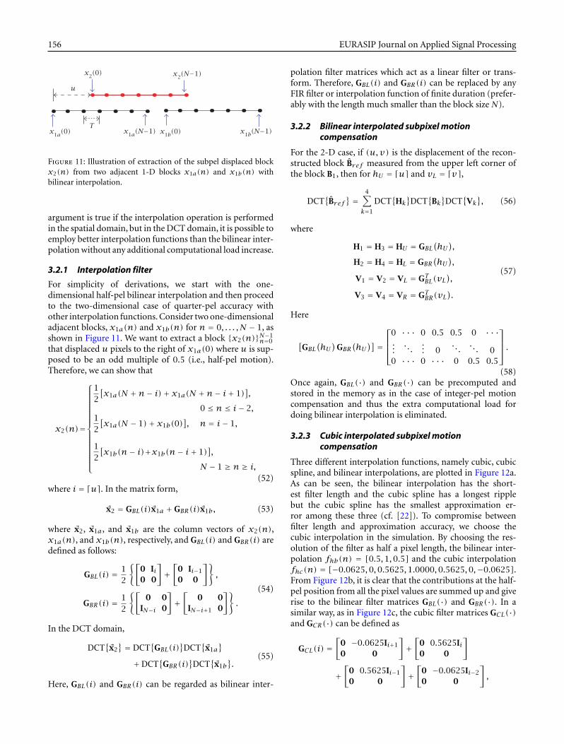
Figure 11: Illustration of extraction of the subpel displaced blockx2(n) from two adjacent 1-D blocks x1a(n) and x1b(n) withbilinear interpolation.
argument is true if the interpolation operation is performedin the spatial domain, but in the DCT domain, it is possible toemploy better interpolation functions than the bilinear inter-polation without any additional computational load increase.
3.2.1 Interpolation filter
For simplicity of derivations, we start with the one-dimensional half-pel bilinear interpolation and then proceedto the two-dimensional case of quarter-pel accuracy withother interpolation functions. Consider two one-dimensionaladjacent blocks, x1a(n) and x1b(n) for n = 0, . . . , N − 1, asshown in Figure 11. We want to extract a block {x2(n)}N−1
n=0
that displaced u pixels to the right of x1a(0) where u is sup-posed to be an odd multiple of 0.5 (i.e., half-pel motion).Therefore, we can show that
x2(n)=
12
[x1a(N +n− i)+ x1a(N +n− i+ 1)
],
0 ≤ n ≤ i− 2,12
[x1a(N − 1)+ x1b(0)
], n = i− 1,
12
[x1b(n− i)+x1b(n− i+ 1)
],
N − 1 ≥ n ≥ i,(52)
where i = �u�. In the matrix form,
�x2 = GBL(i)�x1a +GBR(i)�x1b, (53)
where �x2, �x1a, and �x1b are the column vectors of x2(n),x1a(n), and x1b(n), respectively, and GBL(i) and GBR(i) aredefined as follows:
GBL(i) = 12
{[0 Ii0 0
]+[
0 Ii−1
0 0
]},
GBR(i) = 12
{[0 0
IN−i 0
]+[
0 0IN−i+1 0
]}.
(54)
In the DCT domain,
DCT{�x2} = DCT
{GBL(i)
}DCT
{�x1a
}+DCT
{GBR(i)
}DCT
{�x1b
}.
(55)
Here, GBL(i) and GBR(i) can be regarded as bilinear inter-
polation filter matrices which act as a linear filter or trans-form. Therefore, GBL(i) and GBR(i) can be replaced by anyFIR filter or interpolation function of finite duration (prefer-ably with the length much smaller than the block size N).
3.2.2 Bilinear interpolated subpixel motioncompensation
For the 2-D case, if (u,v) is the displacement of the recon-structed block Bref measured from the upper left corner ofthe block B1, then for hU = �u� and vL = �v�,
DCT{Bref
} = 4∑k=1
DCT{Hk}DCT
{Bk}DCT
{Vk}, (56)
where
H1 = H3 = HU = GBL(hU),
H2 = H4 = HL = GBR(hU),
V1 = V2 = VL = GTBL(vL),
V3 = V4 = VR = GTBR(vL).
(57)
Here
[GBL
(hU)
GBR(hU)] =
0 · · · 0 0.5 0.5 0 · · ·...
. . .... 0
. . .. . . 0
0 · · · 0 · · · 0 0.5 0.5
.(58)
Once again, GBL(·) and GBR(·) can be precomputed andstored in the memory as in the case of integer-pel motioncompensation and thus the extra computational load fordoing bilinear interpolation is eliminated.
3.2.3 Cubic interpolated subpixel motioncompensation
Three different interpolation functions, namely cubic, cubicspline, and bilinear interpolations, are plotted in Figure 12a.As can be seen, the bilinear interpolation has the short-est filter length and the cubic spline has a longest ripplebut the cubic spline has the smallest approximation er-ror among these three (cf. [22]). To compromise betweenfilter length and approximation accuracy, we choose thecubic interpolation in the simulation. By choosing the res-olution of the filter as half a pixel length, the bilinear inter-polation fhb(n) = [0.5,1,0.5] and the cubic interpolationfhc(n) = [−0.0625,0,0.5625,1.0000,0.5625,0,−0.0625].From Figure 12b, it is clear that the contributions at the half-pel position from all the pixel values are summed up and giverise to the bilinear filter matrices GBL(·) and GBR(·). In asimilar way, as in Figure 12c, the cubic filter matrices GCL(·)and GCR(·) can be defined as
GCL(i) =[
0 −0.0625Ii+1
0 0
]+[
0 0.5625Ii0 0
]
+[
0 0.5625Ii−1
0 0
]+[
0 −0.0625Ii−2
0 0
],

Motion compensation on DCT domain 157
Cubic Cubic SplineLinear
−0.2
0
0.2
0.4
0.6
0.8
1
t [T = sampling period]
f(t)
Interpolation functions f(t)
0 2 4 6−6 −4 −2
(a) Different interpolation functions.
0
0.1
0.2
0.3
0.4
0.5
0.6
0.7
0.8
0.9
1
−3 −2 −1 0 1 2 3
t [T = sampling period]
f(t)
Bilinear interpolation f(t)
T
(b) Bilinear interpolation.
0
0.2
0.4
0.6
0.8
1
f(t)
Cubic interpolation f(t)
−4 −3 −2 −1 0 1 2 3 4
t [T = sampling period]
T
(c) Cubic interpolation.
−0.2
0
0.2
0.4
0.6
0.8
1
f(t)
Cubic spline interpolation f(t)
−5 0 1 2 3 4 5
t [T = sampling period]
−4 −3 −2 −1
T
(d) Cubic spline interpolation.
Figure 12: (a) plots of different interpolation functions. (b), (c), and (d) depict how to form a pre- or post-multiplication matrix for half-pelor even quarter-pel DCT-based motion compensation.
GCR(i) =[
0 0−0.0625IN−i−1 0
]+[
0 00.5625IN−i 0
]
+[
0 00.5625IN−i+1 0
]+[
0 0−0.0625IN−i+2 0
].
(59)
Here GCL(·) and GCR(·) can be precomputed and stored.Therefore, its computational complexity remains the sameas both integer-pel and half-pel bilinear interpolated DCT-based motion compensation methods. The reconstructedDCT block and the corresponding motion-compensated
residual can be obtained in a similar fashion:
DCT{Bref
} = 4∑k=1
DCT{Hk}DCT
{Bk}DCT
{Vk},
DCT{DFD
} = DCT{Bref
}−DCT{C},
(60)
where
H1 = H3 = HU = GCL(hU), H2 = H4 = HL = GCR(hU),
V1 = V2 = VL = GTCL(vL), V3 = V4 = VR = GTCR(vL).(61)
158 EURASIP Journal on Applied Signal Processing
This idea can be extended to other interpolation functionssuch as sharped Gaussian [20] and quarter-pel accuracy.
3.3. Interpolation by DCT/DST
Discrete Cosine Transform of type I (DCT-I) or type II (DCT-II) have successfully been applied to discrete interpolationapplications (cf. [23, 24, 25]). Interpolation using DST or themore general W transform has also been studied over theyears (cf. [26, 27]). Interpolation using DCT/DST is foundto surpass the usual DFT interpolation method, especiallyfor sinusoidal inputs, and, by taking into account of theboundary condition, very accurate interpolated values canbe generated [25]. In the following, we will relate DCT-I in-terpolation with the Nyquist sampling theorem and showthat, by means of DCT-I interpolation, the DCT-II coeffi-cients of a half-pel shifted block can be directly obtained fromthe DCT-I coefficients of the original block. In this way, wecan build a DCT-based motion compensation block withoutthe need of converting the DCT coefficients back to pixelsbefore motion compensation as required in the conventionalapproach.
3.3.1 DCT-I interpolated sequence
The procedure of interpolation using DCT-I is given as fol-lows:
(1) Compute the modified DCT-I defined as
Y(m)=DCT-I{y(n)}
= 2NKm
N∑n=0
Kny(n) cos(mnπN
); for m=0, . . . , N,
(62)
where
Km =
12, m = 0, or N,
1, otherwise.(63)
(2) Append zeros to the DCT-I sequence Y(m) to formanother DCT-I sequence Z(m):
Z(m) =Y(m), m = 0, . . . , N,
0, m = N + 1, . . . ,MN.(64)
(3) Obtain the interpolated sequence z(n) by calculatingthe modified inverse DCT-I transform of the zero-padded Z(m) as below:
z(n) = DCT-I−1{Z(m)}
=MN∑m=0
Z(m) cos(mnπMN
); for n = 0, . . . ,MN.
(65)
The above interpolation procedure of using DCT-I can beshown to be equivalent to upsampling of the reconstructed
bandlimited signal from the sequence y(n) by a pair of sinc-like η functions. By defining
Qc(n, ν) � 2NKn
N∑m=0
Km cos(mnπN
)cos
(mνπN
), (66)
the interpolated sequence is
z(n) =N∑
n′=0
y(n′)Qc(n′,
nM
). (67)
Notice that
Qc(n, ν) = KnN
N∑m=0
Km cosmπN(n− ν)
+N∑
m=0
Km cosmπN(n+ ν)
= KnN{η(n− ν)+ η(n+ ν)},
(68)
where
η(x) �N∑
m=0
Km cosmπN(x). (69)
It can be shown that
η(x)= 12
sinπx · cos(πx/2N)sin(πx/2N)
≈Nsinc (x) if πx� 2N.
(70)Since the orthogonal equation is
2NKm
N∑n=0
Kn cos(m′nπN
)cos
(mnπN
)= δ(m′ −m),
(71)we can show that
Qc(n, ν) = δ(n− ν) if ν is an integer. (72)
Therefore, z(nM) = y(n) for n = 0, . . . , N. This satisfies therequirement of being an interpolation function.
From the Nyquist sampling theorem, a continuous ban-dlimited signal, f(t), can be perfectly reconstructed from itssampled sequence, f(nT) for the sampling interval T by aseries of sinc functions (see [28, 29])
f(t) =∞∑
n=−∞f(nT)sinc
(n− t
T
). (73)
The reconstructed f(t) can then be resampled at a differ-ent sampling rate, T1 = T/M , to generate an interpolatedsequence f(mT1).
f(mT1
) = f(mT/M) = ∞∑n=−∞
f(nT)sinc(n− m
M
). (74)
Therefore, interpolation using DCT-I expressed in (67) is thetruncated version of (74) for a symmetric sequence f(nT).
Motion compensation on DCT domain 159
2 4 6 8 10 12 14
45
50
55
60
65
70
75
80
Frame number
MSE
per
pix
el
Half-pel motion compensation on Infrared Car
Cubic Linear
2 4 6 8 10 12 140
500
1000
1500
2000
Frame number
MSE
per
pix
el
Half-pel motion compensation on Infrared Car
Cubic
Linear
Zero-order
(a) Infrared Car sequence.
5 10 15 20 25 30
13
14
15
16
17
18
19
20
21
Frame number
MSE
per
pix
el
Half-pel motion compensation on Miss America
Cubic Linear
5 10 15 20 25 300
50
100
150
200
250
300
Frame number
MSE
per
pix
elHalf-pel motion compensation on Miss America
Cubic
Linear Zero-order
(b) Miss America sequence.
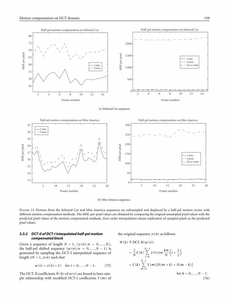
Figure 13: Pictures from the Infrared Car and Miss America sequences are subsampled and displaced by a half-pel motion vector withdifferent motion compensation methods. The MSE-per-pixel values are obtained by comparing the original unsampled pixel values with thepredicted pixel values of the motion compensated residuals. Zero-order interpolation means replication of sampled pixels as the predictedpixel values.
3.3.2 DCT-II of DCT-I interpolated half-pel motioncompensated block
Given a sequence of length N + 1, {y(n);n = 0, . . . , N},the half-pel shifted sequence {w(n);n = 0, . . . , N − 1} isgenerated by sampling the DCT-I interpolated sequence oflength 2N + 1, z(n) such that
w(i) = z(2i+ 1) for i = 0, . . . , N − 1. (75)
The DCT-II coefficientsW(k) ofw(i) are found to have sim-ple relationship with modified DCT-I coefficients Y(m) of
the original sequence y(n) as follows:
W(k) � DCT-II{w(i)}
= 2NC(k)
N−1∑i=0
z(i) coskπN
(i+ 1
2
)
= C(k)N−1∑m=0
Y(m)[δ(m+ k)+ δ(m− k)]
for k = 0, . . . , N − 1.(76)

160 EURASIP Journal on Applied Signal Processing
Therefore,
W(0) =√
2Y(0); W(k) = Y(k) for k = 1, . . . , N − 1.(77)
With this simple relationship, once the modified DCT-Icoefficients of an N + 1 sequence are obtained, the DCT-IIof the DCT-I interpolated half-pel shifted block will easily beobtained via (77).
3.3.3 Simulation results
Simulation is performed on the Infrared Car and Miss Amer-ica sequences to demonstrate the effectiveness of our bilinearand cubic motion compensation methods.
The first set of simulations subsamples each pictureIt(i, j) from the sequences (i.e., y(i, j) = It(2 ∗ i,2 ∗ j))and then this shrinked picture y(i, j) is displaced by a half-pel motion vector (arbitrarily chosen as (2.5,1.5)) with bothbilinear and cubic interpolated motion compensation meth-ods. The mean square errors per pixel (MSE) are computed asMSE = (∑i,j[x(i, j)− x(i, j)]2)/N2 by treating the originalunsampled pixels It(2∗i+1,2∗j+1) as the reference picturex(i, j) = It(2∗ i+1,2∗j+1)where x(i, j) is the predictedpixel value from y(i, j). As shown in Figure 13, the zero-order interpolation is also simulated for comparison. Thezero-order interpolation, also called sample-and-hold inter-polation, simply takes the original pixel value as the predictedhalf-pel pixel value [21]. As can be seen in Figure 13, both thebilinear and cubic methods have much lower MSE values thanthe zero-order method and also the cubic method performsmuch better than the bilinear counterpart without increasedcomputational load.
Figures 14 and 15 show the results of another set of sim-ulations in which the subpixel DCT-based motion compen-sation algorithms generate motion compensated residuals ofthe sequences“Infrared Car”and“Miss America,”respectively,based on the displacement estimates of the full search blockmatching algorithm, where the residuals are used to computethe MSE and BPS values for comparison. It can be seen thatthe cubic interpolation approach achieves lower MSE andBPS values than the bilinear interpolation.
4. CONCLUSION
Despite the conceptual simplicity in the conventional hybridDCT motion compensated codec structures adopted forimplementation of most DCT-based video coding standards,an alternative DCT-based video codec structure has been pro-posed in the past to address a number of shortcomings in-herent in the conventional hybrid architecture. However, noprior research has been directed at what criteria can allowthese two drastically different architectures to interoperatewith each other in accordance with the standards.
In this paper, we establish the criteria for matching con-ventional codecs with fully DCT-based codecs such that com-patibility with existing standards and interoperability witheach other are guaranteed. We find that the key to this in-teroperability lies in the heart of the implementation ofmotion compensation modules performed in the spatial and
2 4 6 8 10 12 1435
40
45
50
55
60
65Infrared Car (hca)
Frame number
Mea
n s
quar
e er
ror
per
pel (
MSE
)
Half-Pel Bilinear Half-Pel CubicQuarter-Pel BilinearQuarter-Pel Cubic
0.76
0.78
0.8
0.82
0.84
0.86
0.88
0.9
0.92Infrared Car (hca)
Frame number (quality = 32)
Bit
s pe
r sa
mpl
e (b
ps)
Half-Pel Bilinear Half-Pel CubicQuarter-Pel BilinearQuarter-Pel Cubic
16
2 4 6 8 10 12 14 16
Figure 14: Pictures from the Infrared Car sequence are subsampledand displaced by a half-pel motion vector with different motioncompensation methods. The MSE-per-pixel values are obtained bycomparing the original unsampled pixel values with the predictedpixel values of the motion compensated residuals. Zero-order in-terpolation means replication of sampled pixels as the predictedpixel values.
transform domains at both the encoder and the decoder.Specifically, if the spatial-domain motion compensation iscompatible with the transform-domain motion compensa-tion, then the states in both the coder and the decoder willkeep track of each other even after a long series of P-frames.Otherwise, the states will diverge in proportion to the num-ber of P-frames between two I-frames. This sets an impor-tant criterion for the development of any DCT-based motioncompensation schemes.
Following this criterion, we also discuss and develop someDCT-based motion compensation schemes as importantbuilding blocks of fully DCT-based codecs. For the caseof subpixel motion compensation, DCT-based approaches

Motion compensation on DCT domain 161
0 50 100 1501
2
3
4
5
6
7
8
9
Half-Pel BilinearHalf-Pel CubicQuarter-Pel BilinearQuarter-Pel Cubic
Mis America in QCIF (hms)
Frame number
Mea
n s
quar
e er
ror
per
pel (
MSE
)
0 50 100 1500.23
0.24
0.25
0.26
0.27
0.28
0.29
0.3
0.31
0.32
0.33
Half-Pel BilinearHalf-Pel CubicQuarter-Pel BilinearQuarter-Pel Cubic
Miss America in QCIF (hms)
Frame number (quality = 32)
Bit
s pe
r sa
mpl
e (b
ps)
Figure 15: Pictures from the Miss America sequence are subsam-pled and displaced by a half-pel motion vector with different motioncompensation methods. The MSE-per-pixel values are obtained bycomparing the original unsampled pixel values with the predictedpixel values of the motion compensated residuals. Zero-order in-terpolation means replication of sampled pixels as the predictedpixel values.
allow more accurate interpolation without any increase incomputation. Furthermore, a scare number of DCT coeffi-cients after quantization significantly decreases the numberof calculations required for motion compensation. Coupledwith the DCT-based motion estimation algorithms, it is pos-sible to realize fully DCT-based codecs to overcome the dis-advantages of conventional hybrid codecs.
REFERENCES
[1] CCITT Recommendation H.261, Video Codec for AudiovisualServices at p × 64 kbit/s, CCITT, August 1990.
[2] CCITT Recommendation MPEG-1, Coding of Moving Pictures
and Associated Audio for Digital Storage Media at up to about1.5 Mbit/s, ISO/IEC 11172, Geneve, Switzerland, 1993.
[3] CCITT Recommendation MPEG-2, Generic Coding of MovingPictures and Associated Audio, ISO/IEC 13818, Geneve, Switzer-land, 1994 H.262.
[4] J. S. McVeigh and S.-W. Wu, “Comparative study of partialclosed-loop versus open-loop motion estimation for coding ofHDTV,” in Proc. IEEE Workshop on Visual Signal Processing andCommunications, New Brunswick, September 1994, pp. 63–68.
[5] H. Li, A. Lundmark, and R. Forchheimer, “Image sequencecoding at very low bitrates: a review,” IEEE Trans. Image Pro-cessing, vol. 3, no. 5, pp. 589–609, 1994.
[6] U. V. Koc and K. J. R. Liu, “DCT-based motion estimation,”IEEE Trans. Image Processing, vol. 7, no. 7, pp. 948–965, 1998.
[7] U. V. Koc and K. J. R. Liu, “Interpolation-free subpixel motionestimation techniques in DCT domain,” IEEE Trans. Circuitsand Systems for Video Technology, vol. 8, no. 4, pp. 460–487,1998.
[8] N. Merhav and V. Bhaskaran, “Fast algorithms for DCT-domain image downsampling and for inverse motion compen-sation,” IEEE Trans. Circuits and Systems for Video Technology,vol. 7, no. 3, pp. 468–476, 1997.
[9] M. Song, A. Cai, and J. A. Sun, “Motion estimation in DCTdomain,” in Proceedings of International Conference on Com-munication Technology (ICCT), 1996, vol. 2, pp. 670–674.
[10] S. Ji and H. W. Park, “Moving object segmentation in DCT-based compressed video,” Electronics Letters, vol. 36, no. 21, pp.1769–1770, 2000.
[11] J. Song and B.-L. Yeo, “A fast algorithm for DCT-domain in-verse motion compensation based on shared information in amacroblock,” IEEE Trans. Circuits and Systems for Video Tech-nology, vol. 10, no. 5, pp. 767–775, 2000.
[12] R. Kleihorst and F. Cabrera, “Implementation of DCT-domainmotion estimation and compensation,” in IEEE Workshop onSignal Processing Systems, October 1998, pp. 53–62.
[13] S. F. Chang and D. G. Messerschmitt, “A new approach todecoding and compositing motion-compensated DCT-basedimages,” in Proc. IEEE Int. Conf. Acoustics, Speech, Signal Pro-cessing, April 1993, vol. V, pp. 421–424.
[14] S.-F. Chang and D. G. Messerschmitt, “Manipulation and com-positing of MC-DCT compressed video,” IEEE Journal on Se-lected Areas in Communications, vol. 13, no. 1, pp. 1–11, 1995.
[15] Y. Y. Lee and J. W. Woods, “Video post-production with com-pressed images,” SMPTE Journal, vol. 103, pp. 76–84, February1994.
[16] B. C. Smith and L. Rowe, “Algorithms for manipulating com-pressed images,” IEEE Computer Graphics and Applications, vol.13, no. 5, pp. 34–42, 1993.
[17] J.-B. Lee and B. G. Lee, “Transform domain filtering based onpipelining structure,” IEEE Trans. Signal Processing, vol. 40, pp.2061–2064, August 1992.
[18] N. Merhav and V. Bhaskaran, “A fast algorithm for DCT-domain inverse motion compensation,” in Proc. IEEE Int. Conf.Acoustics, Speech, Signal Processing, Atlanta, May 1996, vol. IV,pp. 2307–2310.
[19] R. W. Schafer and L. R. Rabiner, “A digital signal processingapproach to interpolation,” Proceedings of the IEEE, vol. 61, no.6, pp. 692–702, 1973.
[20] W. F. Schreiber, Fundamentals of Electronic Imaging Systems—Some Aspects of Image Processing, Springer-Verlag, 3rd edition,1993.
[21] A. K. Jain, Fundamentals of Digital Image Processing, Prentice-Hall, 1989.
[22] H. Hou and H. C. Andrews, “Cubic splines for image interpo-lation and digital filtering,” IEEE Trans. Acoustics, Speech, andSignal Processing, vol. 26, no. 6, pp. 508–517, 1978.

162 EURASIP Journal on Applied Signal Processing
[23] Z. Wang,“Interpolation using type I discrete cosine transform,”Electronics Letters, vol. 26, no. 15, pp. 1170, 1990.
[24] J. I. Agbinya, “Interpolation using the discrete cosine trans-form,” Electronics Letters, vol. 28, no. 20, pp. 1927, 1992.
[25] C.-Y. Hsu and S.-M. Chen, “Discrete interpolation using thediscrete cosine transform with the mapping of the boundaryconditions,” IEEE Signal Processing Letters, vol. 2, no. 10, pp.185, 1995.
[26] Z. Wang and L. Wang, “Interpolation using the fast sine trans-form,” Signal Processing, vol. 26, no. 2, pp. 131–137, 1992.
[27] Z. Wang, G. A. Jullien, and W. C. Miller, “The generalized dis-crete W transform and its application to interpolation,” SignalProcessing, vol. 36, no. 1, pp. 99–109, 1994.
[28] A. V. Oppenheim and R. W. Schafer, Discrete-Time Signal Pro-cessing, Signal Processing. Prentice Hall, New Jersey, 1989.
[29] S. P. Kim and W.-Y. Su, “Direct image resampling using blocktransform coefficients,” Signal Processing: Image Communica-tion, vol. 5, no. 3, pp. 259–272, 1993.
Ut-Va Koc is a Distinguished Member ofTechnical Staff (DMTS) at Bell Labs Re-search, Lucent Technologies, Murray Hill,New Jersey. He has published numerouspeer-reviewed papers and book chapters onsignal processing in multimedia and com-munications. Dr Koc has been active in serv-ing as reviewer of various journals and con-ferences, editor for EURASIP Journal of Ap-plied Signal Processing and guest co-chairin various international conferences. He received the Ph.D. degreefrom the University of Maryland, College Park and the B.S. degreefrom the National Chiao Tung University.
K. J. Ray Liu received the B.S. degree fromthe National Taiwan University, and thePh.D. degree from UCLA, both in electri-cal engineering. He is a Professor of Elec-trical and Computer Engineering Depart-ment and Institute for Systems Researchof University of Maryland, College Park.His research interests span broad aspectsof signal processing algorithms and archi-tectures; image/video compression, coding,and processing; wireless communications; security; and medicaland biomedical technology in which he has published over 200 pa-pers. Dr Liu received numerous awards including the 1994 NationalScience Foundation Young Investigator, the IEEE Signal ProcessingSociety’s 1993 Senior Award (Best Paper Award), IEEE VehicularTechnology Conference Best Paper Award, Amsterdam, 1999, andthe George Corcoran Award in 1994 for outstanding contributionsto electrical engineering education and the Outstanding SystemsEngineering Faculty Award in 1996 in recognition of outstandingcontributions in interdisciplinary research, both from the Univer-sity of Maryland. Dr Liu is Editor-in-Chief of EURASIP Journal onApplied Signal Processing, and has been an Associate Editor of IEEETransactions on Signal Processing, a Guest Editor of special issueson Multimedia Signal Processing of Proceedings of the IEEE,a GuestEditor of special issue on Signal Processing for Wireless Commu-nications of IEEE Journal of Selected Areas in Communications, aGuest Editor of special issue on Multimedia Communications overNetworks of IEEE Signal Processing Magazine, a Guest Editor ofspecial issue on Multimedia over IP of IEEE Trans. on Multimedia,and an editor of Journal of VLSI Signal Processing Systems. He cur-rently serves as the Chair of Multimedia Signal Processing TechnicalCommittee of IEEE Signal Processing Society and the Series Editorof Marcel Dekker series on signal processing and communications.

EURASIP JOURNAL ON ADVANCES IN SIGNAL PROCESSING
Special Issue on
Multihop-Based Cellular Networks
Call for Papers
The deployment of 3G cellular networks is intended to meetthe rapidly increasing number of mobile subscribers and thegrowing demand for new high data rate services such asmobile Internet, video conferencing, and interactive gam-ing. With the anticipated growth rates in cellular commu-nications, the demand is still likely to exceed the availableresources. This fact necessitates research towards practicalcapacity/coverage enhancement and power reduction tech-niques for the evolution of cellular networks towards 4 G.
Motivated by a growing number of applications, there hasbeen recently elevated interest in the design of wireless adhoc networks that do not depend on a fixed infrastructurewhere nodes communicate via multihop transmission. Mul-tihop transmission can possibly lead to coverage extension,capacity enhancement, QoS improvement, and power reduc-tion. Deploying wireless ad hoc network architectures for alarge-scale personal wireless communication system in whichany mobile station (MS) can communicate with its base sta-tion (BS) via an arbitrary number of hops may not be practi-cally feasible. Therefore, it is prudent to combine the benefitsof the centralized architecture of traditional wireless cellularnetworks with the distributed architecture of pure wirelessad hoc networks into a joint design that allows for controlledmultihop transmissions in cellular networks. In multihop-based cellular networks, an MS which meets a predefined setof conditions, for example, is located in a specific area insidethe cell or cannot establish a direct connection with the BS,will use other mobile or fixed stations as relays to communi-cate with its BS. To enable the successful and efficient inte-gration of multihop transmission in cellular networks, thereis an essential need for signal processing research to addressa wide range of problems.
Original contributions are solicited related to all aspects ofsignal processing for multihop-based cellular networks. Top-ics of interest include, but are not limited to:
• Performance analysis• Advanced antenna techniques• Centralized and decentralized detection and estima-
tion
• Distributed signal processing algorithms• Cooperative diversity and coding techniques• Cross-layer designs• Resource allocation algorithms• QoS support mechanisms• Channel modeling• Synchronization and localization• Test bed design and experimental measurements
Authors should follow the EURASIP Journal on Ad-vances in Signal Processing manuscript format describedat the journal site http://www.hindawi.com/journals/asp/.Prospective authors should submit an electronic copy oftheir complete manuscript through the EURASIP Journalon Advances in Signal Processing Manuscript Tracking Sys-tem at http://mts.hindawi.com/ according to the followingtimetable:
Manuscript Due July 1, 2007
First Round of Reviews November 1, 2007
Publication Date February 1, 2008
Guest Editors:
Zaher Dawy, Department of Electrical and Computer En-gineering, American University of Beirut, P.O. Box 11-0236,Bliss Street, Beirut 1107 2020, Lebanon;[email protected]
Mischa Dohler, France Telecom R&D, 38243 Meylan,France; [email protected]
Georgio B. Giannakis, Department of Electrical and Com-puter Engineering, University of Minnesota, Minneapolis,MN 55455-0167, USA;[email protected]
Jing Wang, School of Information Science and Technology,Tsinghua University, Beijing 100084, China;[email protected]
Hindawi Publishing Corporationhttp://asp.hindawi.com

EURASIP Book Series on SP&C, Volume 4, ISBN 977-5945-18-6Please visit http://www.hindawi.com/spc.4.html for more information about the book. To place an order while taking advantage of our current promotional offer, please contact [email protected]
The popularity of multimedia content has led to the widespread distribution and consumption of digital multimedia data. As
a result of the relative ease with which individuals may now alter and repackage digital content, ensuring that media content is employed by authorized users for its intended purpose, is becoming an issue of eminent importance to both governmental security and commercial applications. Digital fingerprinting is a class of multimedia forensic technologies to track and identify entities involved in the illegal manipulation and unauthorized usage of multimedia content, thereby protecting the sensitive nature of multimedia data as well as its commercial value after the content has been delivered to a recipient.
Multimedia Fingerprinting Forensics for Traitor Tracing covers the essential aspects of research in this emerging technology, and explains the latest development in this field. It describes the framework of multimedia fingerprinting, discusses the challenges that may be faced when enforcing usage polices, and investigates the design of fingerprints that cope with new families of multiuser attacks that may be mounted against media fingerprints. The discussion provided in the book highlights challenging problems as well as future trends in this research field, providing readers with a broader view of the evolution of the young field of multimedia forensics.
Topics and features: Comprehensive coverage of digital watermarking and fingerprinting in multimedia forensics for a number of media
types. Detailed discussion on challenges in multimedia fingerprinting and analysis of effective multiuser collusion attacks on
digital fingerprinting. Thorough investigation of fingerprint design and performance analysis for addressing different application concerns
arising in multimedia fingerprinting. Well-organized explanation of problems and solutions, such as order-statistics-based nonlinear collusion attacks, efficient
detection and identification of colluders, group-oriented fingerprint design, and anticollusion codes for multimedia fingerprinting.
Multimedia Fingerprinting Forensics for Traitor TracingK. J. Ray Liu, Wade Trappe, Z. Jane Wang, Min Wu, and Hong Zhao
EURASIP Book Series on Signal Processing and Communications
Limited-Time Promotional Offer. Buy this title NOW at 20% discount plus Free Shipping.
����������������������������������������������������������� ����������
������������������������������������������
���������������������������������������������������������������