Embed Size (px)
Citation preview
MoteTrack: MoteTrack: A Robust, Decentralized Approach to A Robust, Decentralized Approach to RFRF--Based Location TrackingBased Location Tracking
Konrad Lorincz and Matt Welsh
Harvard UniversityDivision of Engineering and Applied Sciences
{konrad, mdw}@eecs.harvard.edu
September 10, 2004
Konrad Lorincz, Harvard University 2
Why Location Tracking is UsefulWhy Location Tracking is Useful
Sensor networks are about “observing events” – for many applications the physical location of the event is important!
Our Primary Focus: Disaster response applications where the robustness of the location-tracking infrastructure is at stake
Konrad Lorincz, Harvard University 3
Why Location Tracking is UsefulWhy Location Tracking is Useful
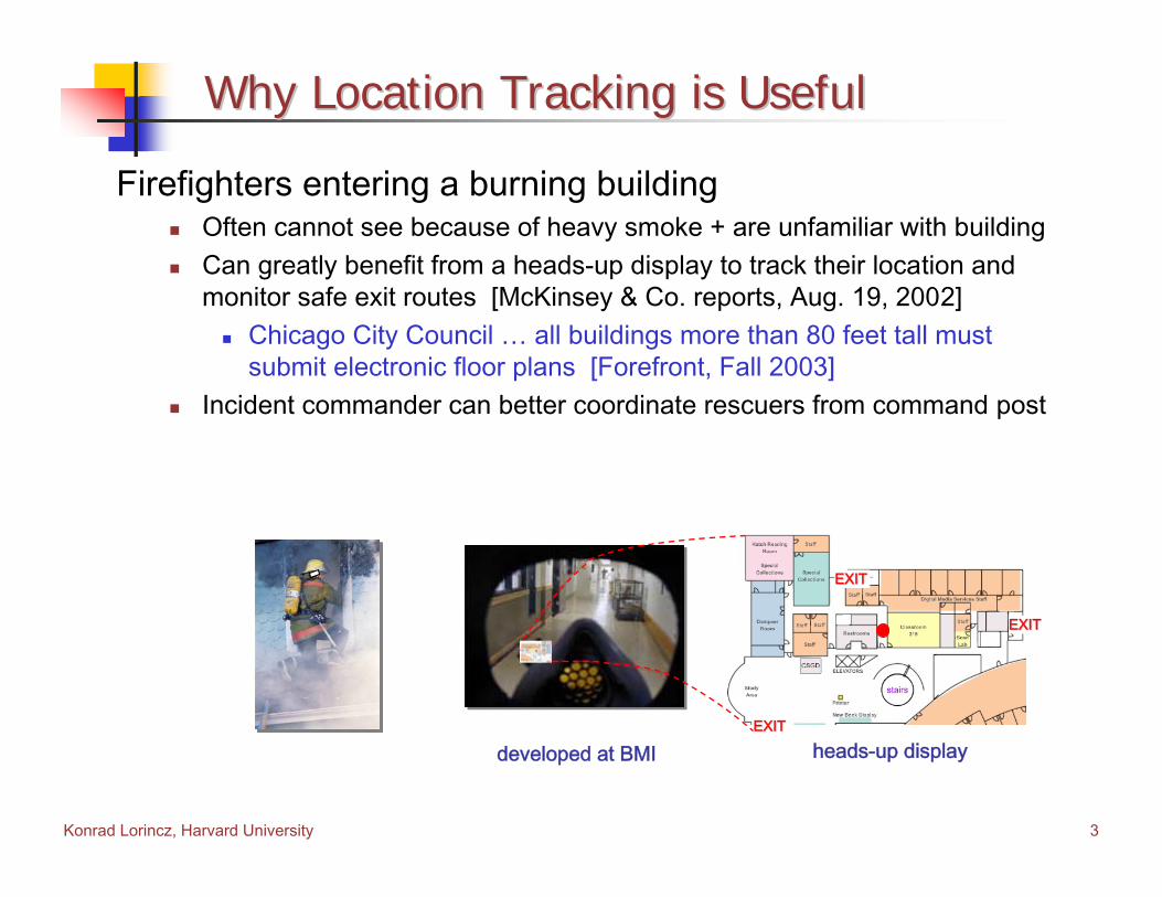
Firefighters entering a burning buildingOften cannot see because of heavy smoke + are unfamiliar with buildingCan greatly benefit from a heads-up display to track their location and monitor safe exit routes [McKinsey & Co. reports, Aug. 19, 2002]
Chicago City Council … all buildings more than 80 feet tall must submit electronic floor plans [Forefront, Fall 2003]
Incident commander can better coordinate rescuers from command post
EXITEXIT
EXITEXIT
EXITEXIT
heads-up displaydeveloped at BMI

Konrad Lorincz, Harvard University 4
Why Location Tracking is UsefulWhy Location Tracking is Useful
Emergency Medical CareMonitor the location of patients with wearable vital sign sensors
Can quickly locate patient that suddenly requires immediate attention(e.g., patient stops breathing)
Monitoring the location of emergency personnel (e.g., EMTs, firefighters)6 firefighters die in Worcester MA fire, [Boston Globe, Dec. 10, 1999]
pulse oximeter
two-led EKG
PDA-based triage app.

Konrad Lorincz, Harvard University 5
OutlineOutline
MotivationIntroductionIntroductionSystem DescriptionImplementation and Data CollectionEvaluationFuture Work and DirectionsConclusions
Konrad Lorincz, Harvard University 6
Requirements and ProblemsRequirements and Problems
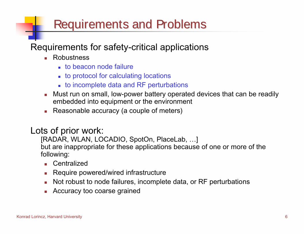
Requirements for safety-critical applicationsRobustness
to beacon node failureto protocol for calculating locationsto incomplete data and RF perturbations
Must run on small, low-power battery operated devices that can be readily embedded into equipment or the environmentReasonable accuracy (a couple of meters)
Lots of prior work: [RADAR, WLAN, LOCADIO, SpotOn, PlaceLab, …] but are inappropriate for these applications because of one or more of the following:
CentralizedRequire powered/wired infrastructureNot robust to node failures, incomplete data, or RF perturbationsAccuracy too coarse grained

Konrad Lorincz, Harvard University 7
Achieving RobustnessAchieving Robustness
Our ApproachBase the location tracking on empirical measurements of radio signals from multiple transmitters, using an algorithm similar to RADARAchieve robustness by extending this approach in 3 significant ways
Use a decentralized approach for computing locations that runs on the beacon nodes, rather than a central serverReplicate the location signature database across the beacon nodes in a fashion that minimizes per-node storage overhead and achieves high robustness to failureEmploy a signature distance metric that adapts to partial failure of beacon nodes, partial information, and perturbations in the RF signal

Konrad Lorincz, Harvard University 8
Platform ChoicePlatform Choice
Why Motes/TinyOS seems to be the right platformSmall size
Easy to embed in environment and equipmentCan operate off of battery + it is low power
Resilient to infrastructure failureWell established platform
Used by over 150 research groups worldwideEasy to integrate new sensors/actuators
Mica2 Dot moteMica2 mote

Konrad Lorincz, Harvard University 9
Why RFWhy RF--basedbased
Why RF-based (Radio Frequency)It’s the “least common denominator” for most wireless sensor networks
Can supplement other wireless sensor networks with location trackingfor little or no additional cost
Benefits of no additional hardwareLower cost and smaller size
“Robust” to the environment Doesn’t require line of sightIs not sensitive to variations of light and temperature

Konrad Lorincz, Harvard University 10
ChallengesChallenges
Accurate RF-based localization with low-power radiosLarge fluctuations in received signal strength indicator (RSSI)No clear correlation with distance
Low device capability and memory sizee.g., Mica2: 4KB RAM, 8-bit CPU, no floating point unitCan’t do real signal processing
RobustnessFailed nodesRF characteristics of building changedIncomplete data

Konrad Lorincz, Harvard University 11
OutlineOutline
MotivationIntroductionSystem DescriptionSystem DescriptionImplementation and Data CollectionEvaluationFuture Work and DirectionsConclusions
Konrad Lorincz, Harvard University 12
HighHigh--level Overview of MoteTracklevel Overview of MoteTrack
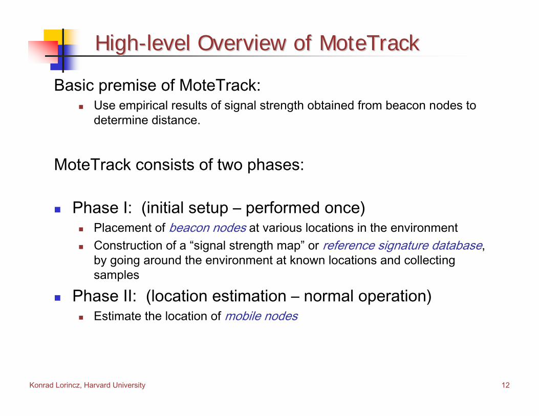
Basic premise of MoteTrack: Use empirical results of signal strength obtained from beacon nodes to determine distance.
MoteTrack consists of two phases:
Phase I: (initial setup – performed once)Placement of beacon nodes at various locations in the environmentConstruction of a “signal strength map” or reference signature database, by going around the environment at known locations and collecting samples
Phase II: (location estimation – normal operation)Estimate the location of mobile nodes
Konrad Lorincz, Harvard University 13
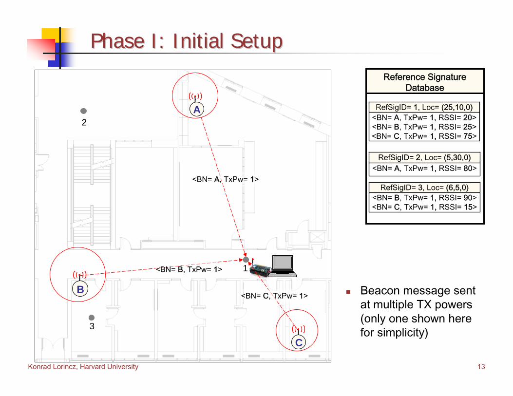
Phase I: Initial SetupPhase I: Initial Setup
Beacon message sent at multiple TX powers(only one shown here for simplicity)
1
<BN= A, TxPw= 1>
A<BN= A, TxPw= 1, RSSI= 20><BN= B, TxPw= 1, RSSI= 25><BN= C, TxPw= 1, RSSI= 75>
RefSigID= 1, Loc= (25,10,0)
<BN= B, TxPw= 1>
<BN= C, TxPw= 1>B
C
<BN= A, TxPw= 1, RSSI= 80>RefSigID= 2, Loc= (5,30,0)
<BN= B, TxPw= 1, RSSI= 90><BN= C, TxPw= 1, RSSI= 15>
RefSigID= 3, Loc= (6,5,0)
Reference Signature Database
2
3
Konrad Lorincz, Harvard University 14
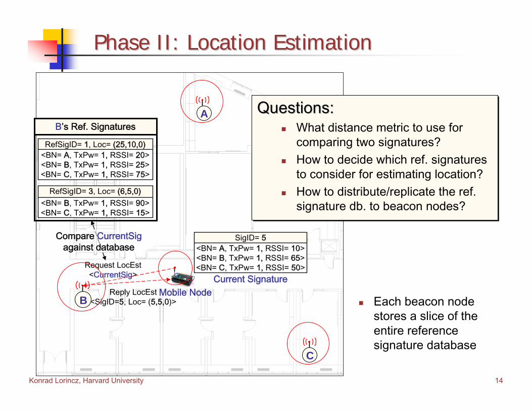
Phase II: Location EstimationPhase II: Location Estimation
Mobile Node
<BN= A, TxPw= 1, RSSI= 10><BN= B, TxPw= 1, RSSI= 65><BN= C, TxPw= 1, RSSI= 50>
Current Signature
SigID= 5
Request LocEst<CurrentSig>
Reply LocEst<SigID=5, Loc= (5,5,0)>
Compare CurrentSigagainst database
A
B
C
<BN= A, TxPw= 1, RSSI= 20><BN= B, TxPw= 1, RSSI= 25><BN= C, TxPw= 1, RSSI= 75>
RefSigID= 1, Loc= (25,10,0)
<BN= B, TxPw= 1, RSSI= 90><BN= C, TxPw= 1, RSSI= 15>
RefSigID= 3, Loc= (6,5,0)
B’s Ref. Signatures
Each beacon node stores a slice of the entire reference signature database
Questions:What distance metric to use for comparing two signatures?How to decide which ref. signatures to consider for estimating location?How to distribute/replicate the ref. signature db. to beacon nodes?
Questions:Questions:What distance metric to use for comparing two signatures?How to decide which ref. signatures to consider for estimating location?How to distribute/replicate the ref. signature db. to beacon nodes?
Konrad Lorincz, Harvard University 15
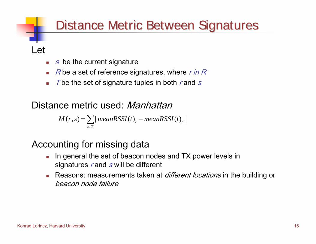
Distance Metric Between SignaturesDistance Metric Between Signatures
Lets be the current signatureR be a set of reference signatures, where r in RT be the set of signature tuples in both r and s
Distance metric used: Manhattan
Accounting for missing dataIn general the set of beacon nodes and TX power levels in signatures r and s will be differentReasons: measurements taken at different locations in the building or beacon node failure
( , ) | ( ) ( ) |r st T
M r s meanRSSI t meanRSSI t∈
= −∑
Konrad Lorincz, Harvard University 16
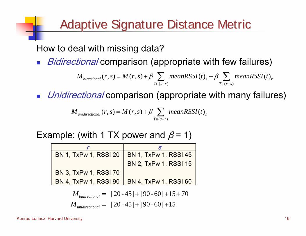
Adaptive Signature Distance MetricAdaptive Signature Distance Metric
How to deal with missing data?Bidirectional comparison (appropriate with few failures)
Unidirectional comparison (appropriate with many failures)
Example: (with 1 TX power and β = 1)
( )
( , ) ( , ) ( )unidirectional sT s r
M r s M r s meanRSSI tβ∈ −
= + ∑
( ) ( )
( , ) ( , ) ( ) ( )birectional s rT s r T r s
M r s M r s meanRSSI t meanRSSI tβ β∈ − ∈ −
= + +∑ ∑
BN 1, TxPw 1, RSSI 45BN 2, TxPw 1, RSSI 15
BN 4, TxPw 1, RSSI 60
BN 1, TxPw 1, RSSI 20
BN 3, TxPw 1, RSSI 70BN 4, TxPw 1, RSSI 90
sr
| 20 - 45 | | 90 - 60 | 15 70 | 20 - 45 | | 90 - 60 | 15
bidirectional
unidirectional
MM
= + + +
= + +

Konrad Lorincz, Harvard University 17
Adaptive Signature Distance MetricAdaptive Signature Distance Metric
Adaptive approachPeriodically estimate the local failure ratio
Take intersection between the current and original neighborhoodsDecide dynamically which comparison algorithm to use
AssumptionsConnectivity between nodes doesn’t change substantially over timeNo beacon node failures between the time the reference signaturedatabase is collected and deployment
Konrad Lorincz, Harvard University 18
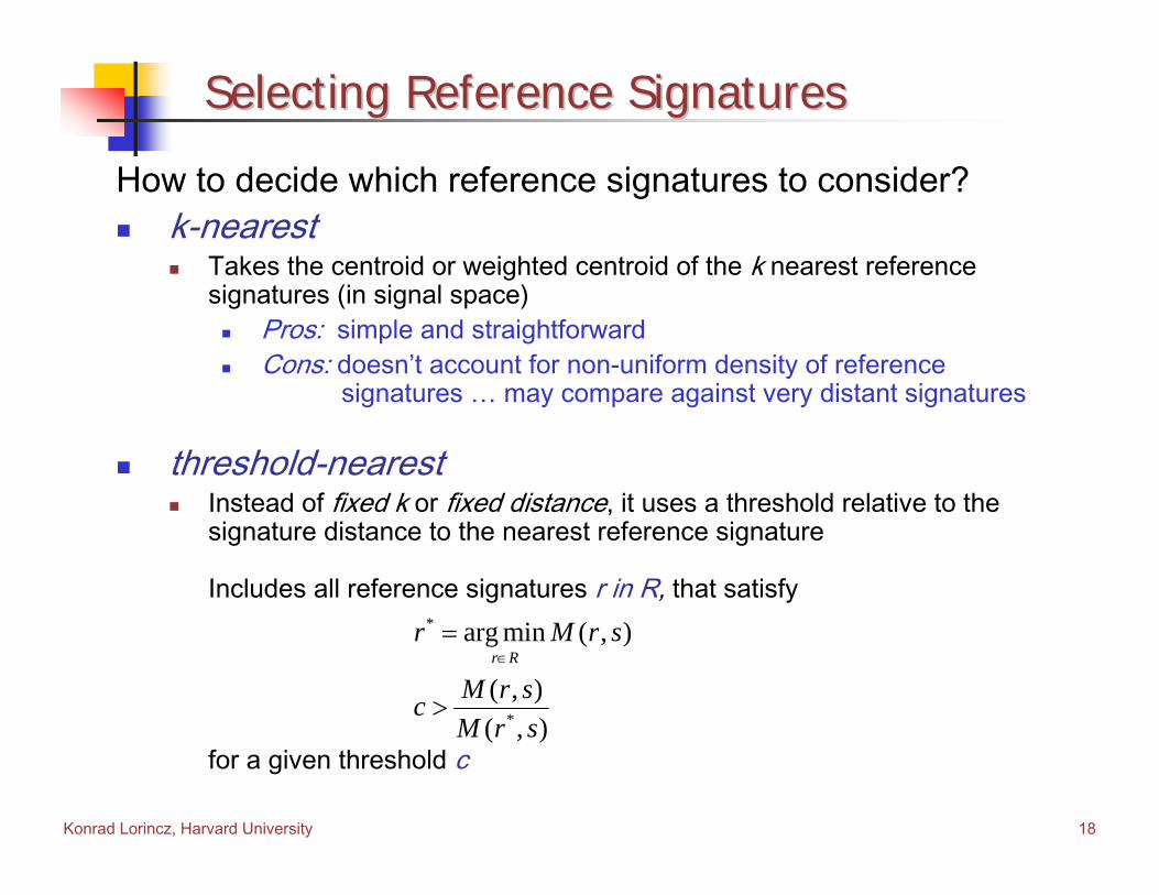
Selecting Reference SignaturesSelecting Reference Signatures
How to decide which reference signatures to consider?k-nearest
Takes the centroid or weighted centroid of the k nearest reference signatures (in signal space)
Pros: simple and straightforwardCons: doesn’t account for non-uniform density of reference
signatures … may compare against very distant signatures
threshold-nearestInstead of fixed k or fixed distance, it uses a threshold relative to the signature distance to the nearest reference signature
Includes all reference signatures r in R, that satisfy
for a given threshold c
*
*
arg min ( , )
( , )( , )
r Rr M r s
M r scM r s
∈=
>
Konrad Lorincz, Harvard University 19
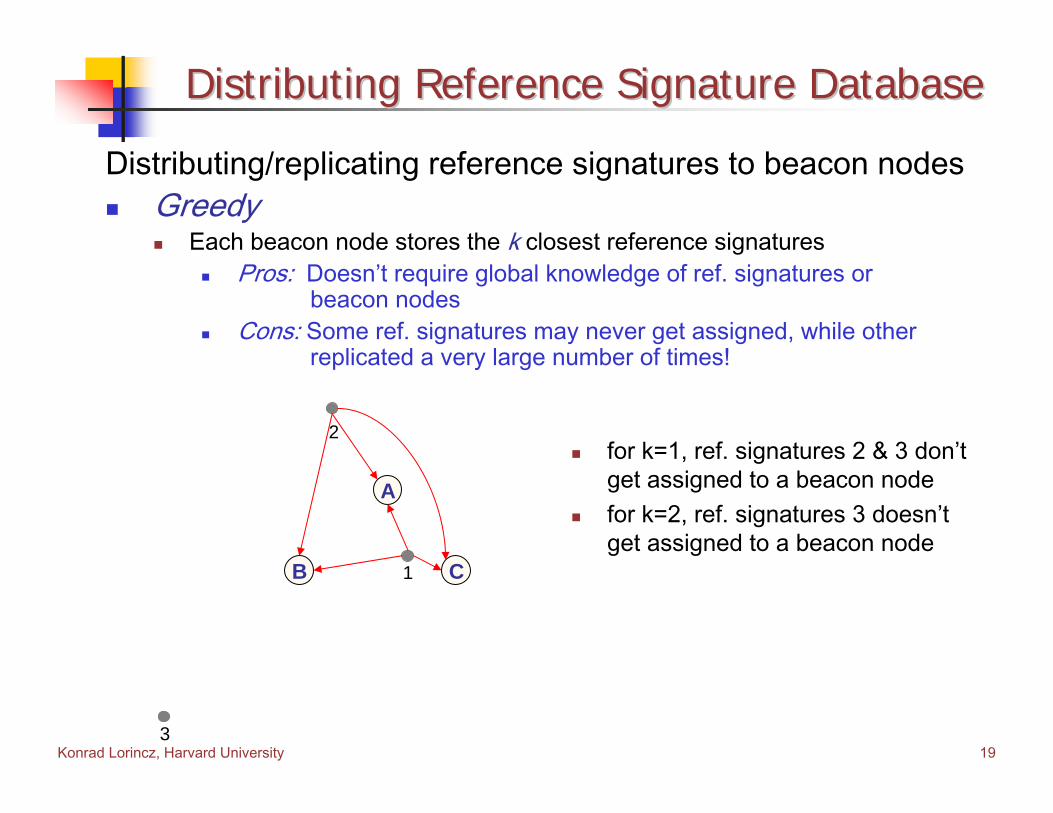
Distributing Reference Signature DatabaseDistributing Reference Signature Database
Distributing/replicating reference signatures to beacon nodesGreedy
Each beacon node stores the k closest reference signaturesPros: Doesn’t require global knowledge of ref. signatures or
beacon nodesCons: Some ref. signatures may never get assigned, while other
replicated a very large number of times!
A
B C1
2
3
for k=1, ref. signatures 2 & 3 don’t get assigned to a beacon nodefor k=2, ref. signatures 3 doesn’t get assigned to a beacon node

Konrad Lorincz, Harvard University 20
Distributing Reference Signature DatabaseDistributing Reference Signature Database
Distributing reference signatures to beacon nodesBalanced
Ensures that each reference signature is replicated k times while trying to pair each beacon node with its closest reference signatures (inspired by the stable marriage algorithm)
Pros: Ensures all ref. sigs. are replicated k timesCons: Requires global knowledge of all ref. sigs. and beacon nodes.
A
B C
time steps
231C123B
312Ak = 3k = 2k = 1nbr rep
1
2
3
Algorithm (high-level)repeat until all ref-sigs are paired k times
Pair next closest <ref-sig, BN> pair, thatdoesn’t violate one of the following
1. no ref-sig is paired with a BN more thanone additional time from any other ref-sig
2. no BN is paired with a ref-sig more thanone additional time from any other BN
Konrad Lorincz, Harvard University 21
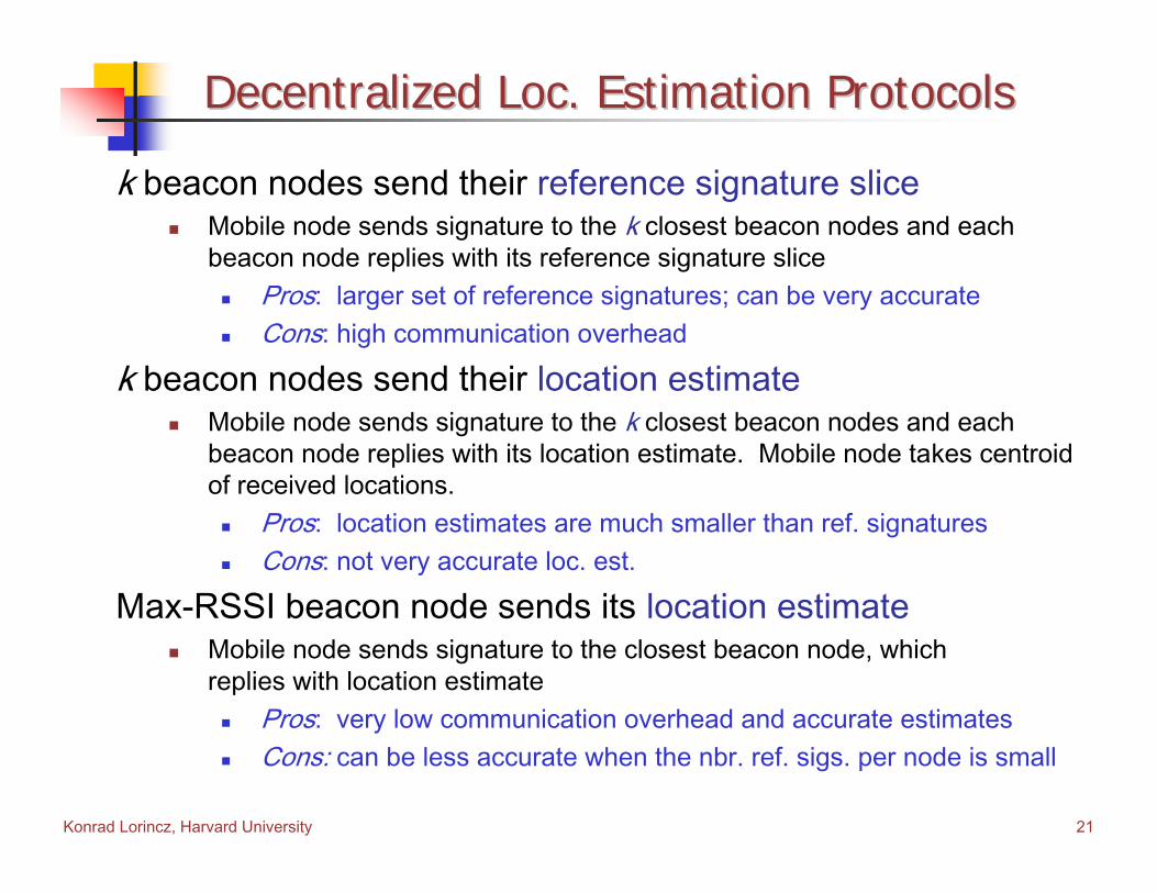
Decentralized Loc. Estimation ProtocolsDecentralized Loc. Estimation Protocols
k beacon nodes send their reference signature sliceMobile node sends signature to the k closest beacon nodes and each beacon node replies with its reference signature slice
Pros: larger set of reference signatures; can be very accurateCons: high communication overhead
k beacon nodes send their location estimateMobile node sends signature to the k closest beacon nodes and each beacon node replies with its location estimate. Mobile node takes centroid of received locations.
Pros: location estimates are much smaller than ref. signaturesCons: not very accurate loc. est.
Max-RSSI beacon node sends its location estimateMobile node sends signature to the closest beacon node, which replies with location estimate
Pros: very low communication overhead and accurate estimatesCons: can be less accurate when the nbr. ref. sigs. per node is small

Konrad Lorincz, Harvard University 22
OutlineOutline
MotivationIntroduction System DescriptionImplementation and Data CollectionImplementation and Data CollectionEvaluationEvaluationFuture Work and DirectionsConclusions
Konrad Lorincz, Harvard University 23
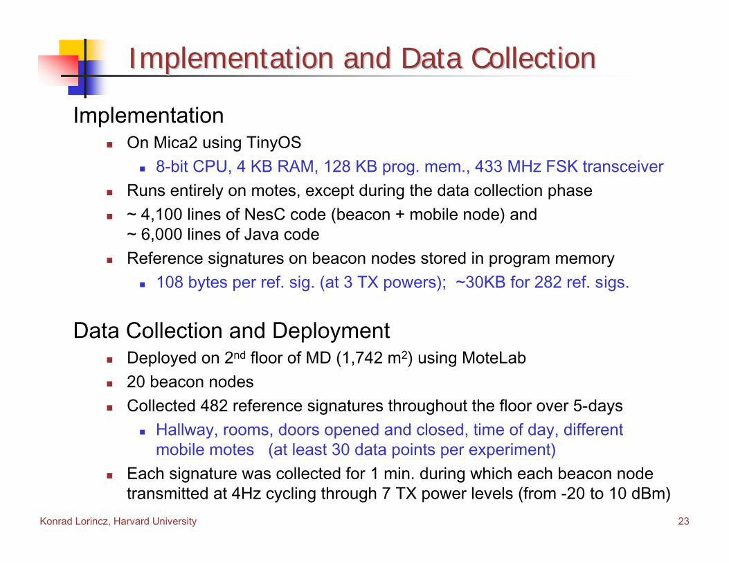
Implementation and Data CollectionImplementation and Data Collection
ImplementationOn Mica2 using TinyOS
8-bit CPU, 4 KB RAM, 128 KB prog. mem., 433 MHz FSK transceiverRuns entirely on motes, except during the data collection phase~ 4,100 lines of NesC code (beacon + mobile node) and~ 6,000 lines of Java codeReference signatures on beacon nodes stored in program memory
108 bytes per ref. sig. (at 3 TX powers); ~30KB for 282 ref. sigs.
Data Collection and DeploymentDeployed on 2nd floor of MD (1,742 m2) using MoteLab20 beacon nodesCollected 482 reference signatures throughout the floor over 5-days
Hallway, rooms, doors opened and closed, time of day, different mobile motes (at least 30 data points per experiment)
Each signature was collected for 1 min. during which each beacon node transmitted at 4Hz cycling through 7 TX power levels (from -20 to 10 dBm)
Konrad Lorincz, Harvard University 24
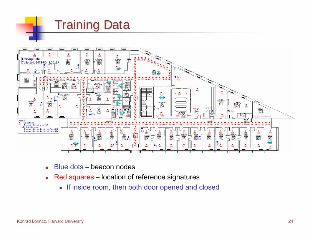
Training DataTraining Data
Blue dots – beacon nodesRed squares – location of reference signatures
If inside room, then both door opened and closed
Konrad Lorincz, Harvard University 25
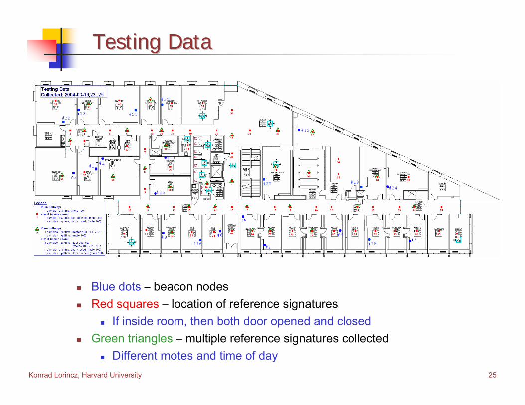
Testing DataTesting Data
Blue dots – beacon nodesRed squares – location of reference signatures
If inside room, then both door opened and closedGreen triangles – multiple reference signatures collected
Different motes and time of day
Konrad Lorincz, Harvard University 26
EvaluationEvaluation
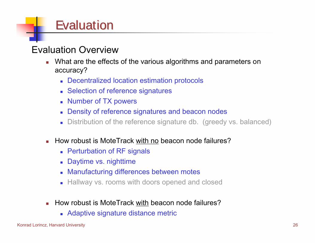
Evaluation OverviewWhat are the effects of the various algorithms and parameters onaccuracy?
Decentralized location estimation protocolsSelection of reference signaturesNumber of TX powersDensity of reference signatures and beacon nodesDistribution of the reference signature db. (greedy vs. balanced)
How robust is MoteTrack with no beacon node failures?Perturbation of RF signalsDaytime vs. nighttime Manufacturing differences between motes Hallway vs. rooms with doors opened and closed
How robust is MoteTrack with beacon node failures?Adaptive signature distance metric
Konrad Lorincz, Harvard University 27
Decentralized Loc. Estimation ProtocolsDecentralized Loc. Estimation Protocols
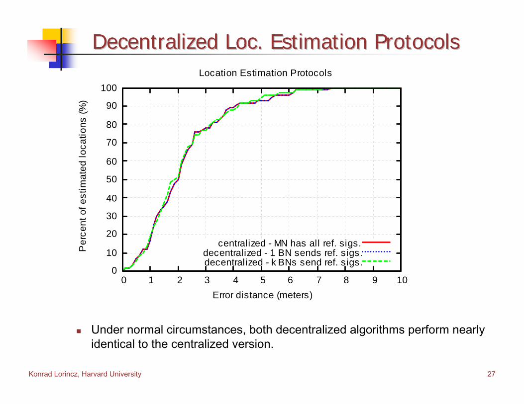
Under normal circumstances, both decentralized algorithms perform nearly identical to the centralized version.
0
10
20
30
40
50
60
70
80
90
100
0 1 2 3 4 5 6 7 8 9 10
Per
cent
of e
stim
ated
loca
tions
(%)
Error distance (meters)
Location Estimation Protocols
centralized - MN has all ref. sigs.decentralized - 1 BN sends ref. sigs.decentralized - k BNs send ref. sigs.
Konrad Lorincz, Harvard University 28
Selection of Reference SignaturesSelection of Reference Signatures
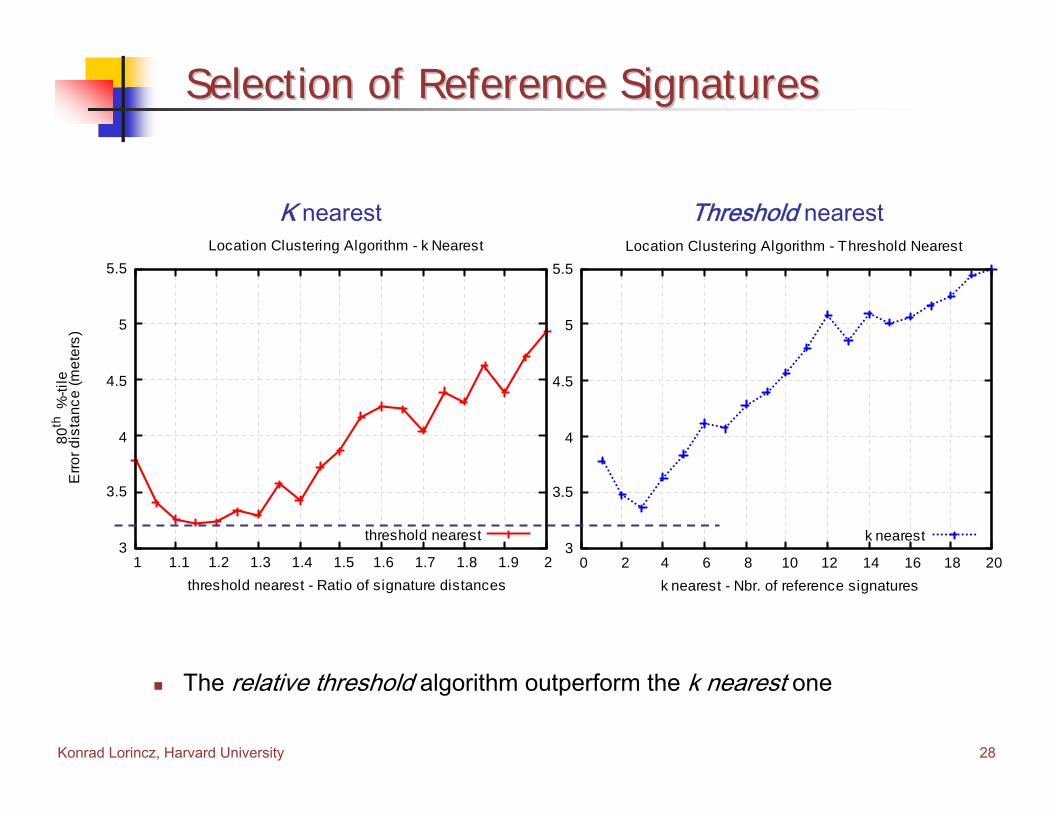
The relative threshold algorithm outperform the k nearest one
3
3.5
4
4.5
5
5.5
0 2 4 6 8 10 12 14 16 18 20
80th
%-ti
leE
rror d
ista
nce
(met
ers)
k nearest - Nbr. of reference signatures
Location Clustering Algorithm - Threshold Nearest
k nearest 3
3.5
4
4.5
5
5.5
1 1.1 1.2 1.3 1.4 1.5 1.6 1.7 1.8 1.9 2
80th
%-ti
leE
rror d
ista
nce
(met
ers)
threshold nearest - Ratio of signature distances
Location Clustering Algorithm - k Nearest
threshold nearest
K nearest Threshold nearest
Konrad Lorincz, Harvard University 29
Number of Transmission PowersNumber of Transmission Powers
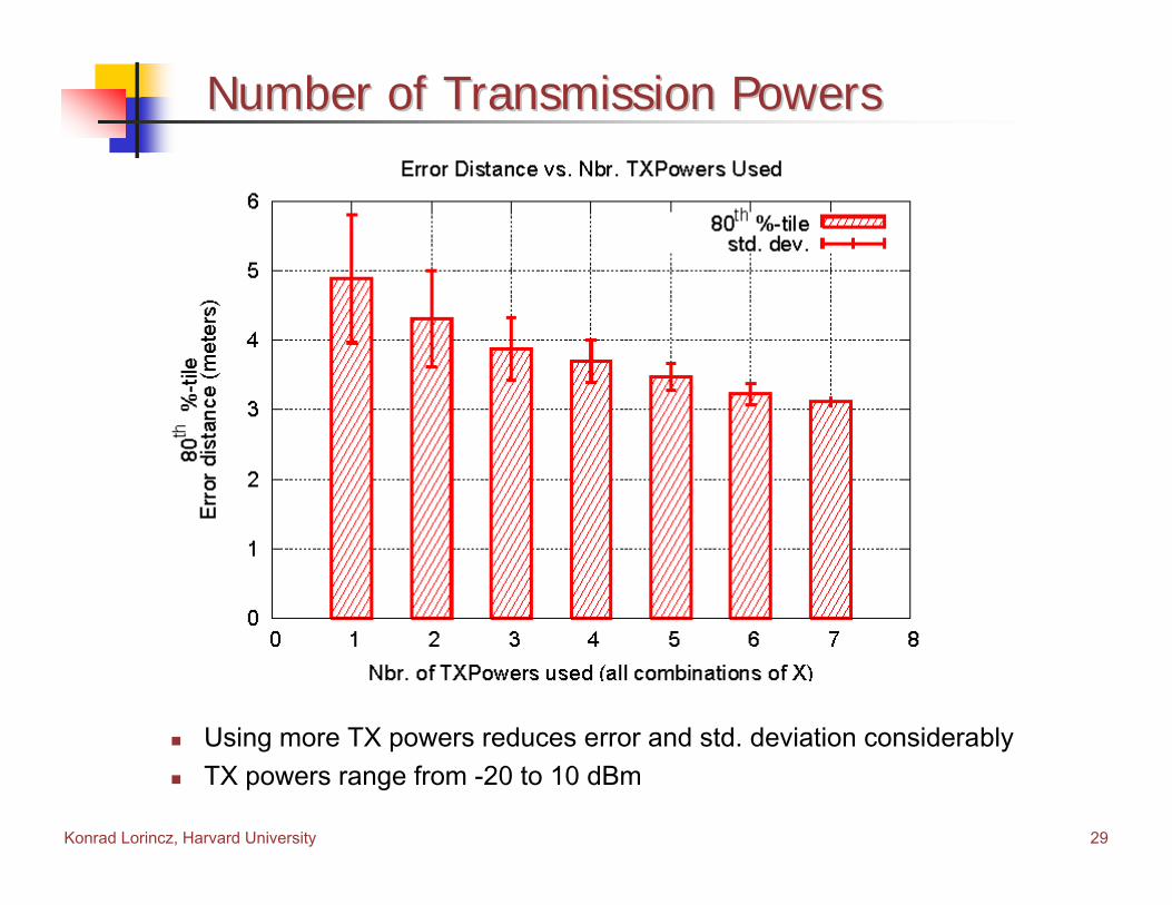
Using more TX powers reduces error and std. deviation considerablyTX powers range from -20 to 10 dBm

Konrad Lorincz, Harvard University 30
Density of Beacon NodesDensity of Beacon Nodes
Critical number is about 6-7 beacon nodes (0.004 beacon nodes/m2)(total area: 1,742 m2 or 18,751 ft2)
0
5
10
15
20
25
30
35
40
45
0 2 4 6 8 10 12 14 16 18 20
Erro
r dis
tanc
e (m
eter
s)
Nbr. of beacon nodes
Density of Beacon Nodes
80th %-tile50th %-tile25th %-tile
Konrad Lorincz, Harvard University 31
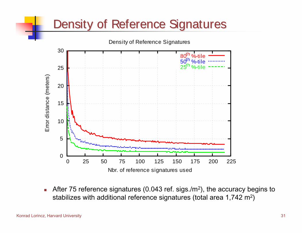
Density of Reference SignaturesDensity of Reference Signatures
After 75 reference signatures (0.043 ref. sigs./m2), the accuracy begins to stabilizes with additional reference signatures (total area 1,742 m2)
0
5
10
15
20
25
30
0 25 50 75 100 125 150 175 200 225
Erro
r dis
tanc
e (m
eter
s)
Nbr. of reference signatures used
Density of Reference Signatures
80th %-tile50th %-tile25th %-tile
Konrad Lorincz, Harvard University 32
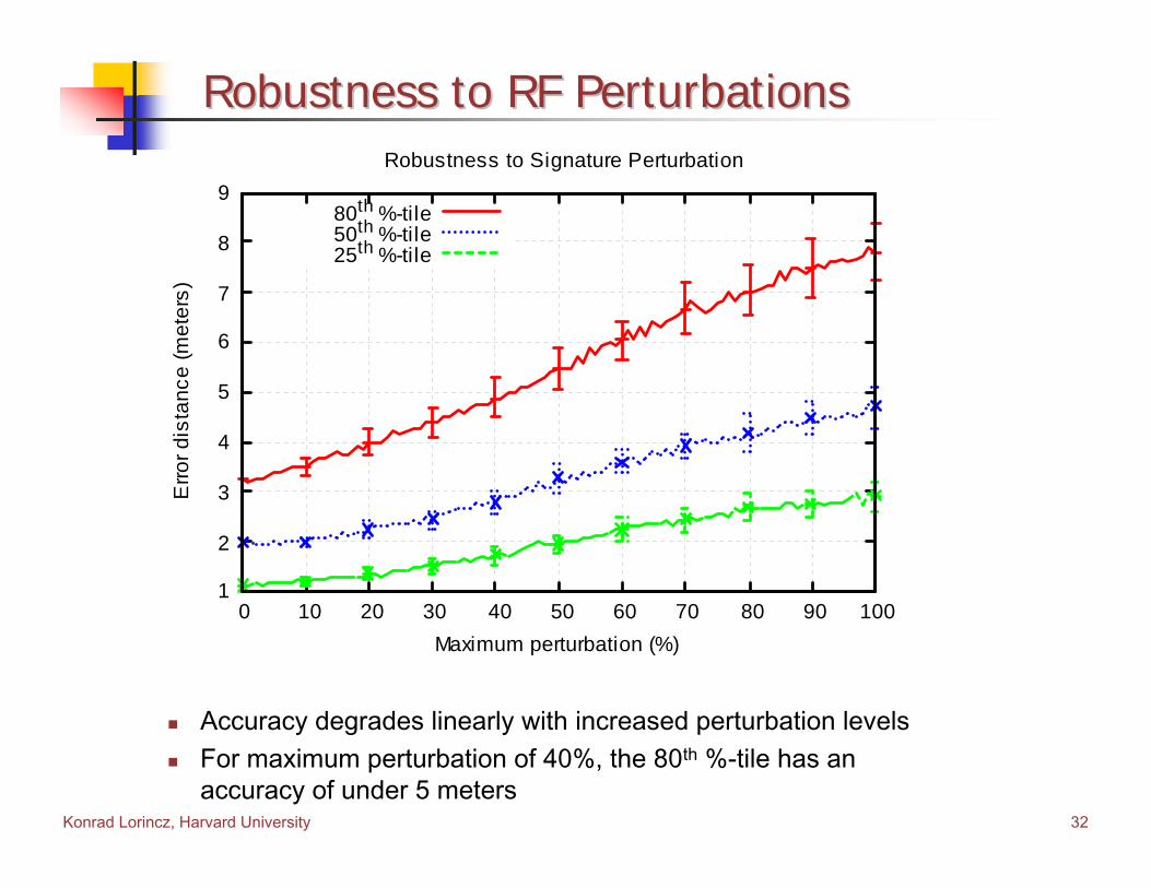
Robustness to RF PerturbationsRobustness to RF Perturbations
Accuracy degrades linearly with increased perturbation levelsFor maximum perturbation of 40%, the 80th %-tile has an accuracy of under 5 meters
1
2
3
4
5
6
7
8
9
0 10 20 30 40 50 60 70 80 90 100
Erro
r dis
tanc
e (m
eter
s)
Maximum perturbation (%)
Robustness to Signature Perturbation
80th %-tile50th %-tile25th %-tile
Konrad Lorincz, Harvard University 33
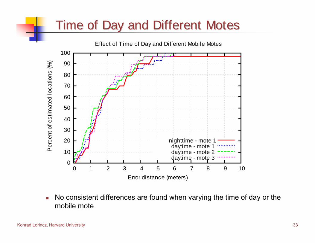
Time of Day and Different MotesTime of Day and Different Motes
No consistent differences are found when varying the time of day or the mobile mote
0
10
20
30
40
50
60
70
80
90
100
0 1 2 3 4 5 6 7 8 9 10
Per
cent
of e
stim
ated
loca
tions
(%)
Error distance (meters)
Effect of T ime of Day and Different Mobile Motes
nighttime - mote 1daytime - mote 1daytime - mote 2daytime - mote 3

Konrad Lorincz, Harvard University 34
Robustness to Beacon Node FailureRobustness to Beacon Node Failure
The unidirectional algorithm is more robust to significant beacon node failures, but yields poorer accuracy for few failures (less than 16%)MoteTrack uses a hybrid approachideal: bidirectional metric only over non-failed nodes (req. perfect knowledge)
0
10
20
30
40
50
60
0 10 20 30 40 50 60 70 80 90
80th
%-ti
leE
rror d
ista
nce
(met
ers)
Percent of failed beacon nodes (%)
Robustness to Beacon Node Failure
unidirectionalbidirectional
ideal
3
4
5
6
7
0 5 10 15 20

Konrad Lorincz, Harvard University 35
Signature Distance AlgorithmsSignature Distance Algorithms
The bidirectional algorithm is more accurate because the comparison space is larger
0
10
20
30
40
50
60
70
80
90
100
0 1 2 3 4 5 6 7 8 9 10
Per
cent
of e
stim
ated
loca
tions
(%)
Error distance (meters)
Signal Distance Algorithms
unidirectionalbidirectional
Konrad Lorincz, Harvard University 36
OutlineOutline
MotivationIntroductionSystem DescriptionImplementation and Data CollectionEvaluationFuture Work and DirectionsFuture Work and DirectionsConclusionsConclusions
Konrad Lorincz, Harvard University 37
Future Work and DirectionsFuture Work and Directions
Ad hoc rapid deployment – automatic calibration via GPS(e.g., on the scene of a train wreck)
Add/remove reference signatures on-the-fly from beacon nodesHow to build up the reference signature database?
Rescue personnel populate beacon nodes with reference signatures as they move about with GPS enabled PDAs
Additional error introduced by the GPS
Immediate futurePort to Telos and MicaZ motes which use the CC2420 802.15.4 radio chipRe-run measurements to compare performance of 433MHz to 2.4GHz
Konrad Lorincz, Harvard University 38
ConclusionsConclusions
Main contributionsExtended the basic RF signature approach to achieve high robustness by:
Decentralizing the location estimation protocol so that it relies only on local communication, data, and operational nodesReplicating the ref. signature database across beacon nodes in afashion that minimizes storage but achieves high level of robustness to failureUsing an dynamic signature distance metric that adapts to locally failed beacon nodes
Negligible error introduced with up to 40% of beacon node failureDemonstrated a complete workable system and performed detail evaluation
AvailabilityMoteTrack 1.0 has been released
Get the latest code from the TinyOS contrib directory on SourceForgeMoteTrack web site:
http://www.eecs.harvard.edu/~konrad/projects/motetrack/