Embed Size (px)
Citation preview
HAL Id: hal-01455300https://hal.inria.fr/hal-01455300
Submitted on 3 Feb 2017
HAL is a multi-disciplinary open accessarchive for the deposit and dissemination of sci-entific research documents, whether they are pub-lished or not. The documents may come fromteaching and research institutions in France orabroad, or from public or private research centers.
L’archive ouverte pluridisciplinaire HAL, estdestinée au dépôt et à la diffusion de documentsscientifiques de niveau recherche, publiés ou non,émanant des établissements d’enseignement et derecherche français ou étrangers, des laboratoirespublics ou privés.
Distributed under a Creative Commons Attribution| 4.0 International License
Reconstruction of Konrad Zuse’s Z3Horst Zuse
To cite this version:Horst Zuse. Reconstruction of Konrad Zuse’s Z3. International Conference on History of Comput-ing (HC), Jun 2013, London, United Kingdom. pp.287-296, �10.1007/978-3-642-41650-7_26�. �hal-01455300�
280
Reconstruction of Konrad Zuse’s Z3
Horst Zuse
Schaperstraße 21, 10719 Berlin, Germany [email protected]
Abstract: This paper describes the reconstruction of Konrad Zuse’s Machine Z3 by the author Horst Zuse from 2008. Konrad Zuse built the Z3 machine between 1939 and 1941 with some friends and a small amount of support by the government. The main idea for reconstructing the Z3 was to learn how this machine works and how much effort is necessary to build such a machine. Another main topic was to show
this machine to the public.
Keywords: Z3, Zuse, computer, freely programmable, reconstruction of the Z3, memory, binary system, floating point numbers
1 Introduction
In this paper we describe the reconstruction of Konrad Zuse’s Machine Z3 by the
author Horst Zuse from 2008.
Today, in the whole world Konrad Zuse almost unanimously is accepted as the
creator / inventor of the first free programmable computer with a binary floating point
and switching system, which really worked. This machine - called Z3 - was
completed in his small workshop in Berlin (Kreuzberg) in 1941. Zuse’s first thoughts
about the logical and technical principles go back to 1934. Konrad Zuse, also created the first programming language (1942-1945) in the world, called the Plankalkül. In
1949 he founded the computer company Zuse KG in Neukirchen (close to Fulda) and
built till 1964 more than 250 computers for universities and companies. Konrad Zuse
was born on June 22, 1910 in Berlin and died on December 18, 1995 in Hünfeld.
2 Konrad Zuse’s First Ideas on Computing
In 1934 Konrad Zuse formulated the first ideas on computing. The reason was the
expensive calculations as a civil engineer. His idea was that such stupid calculations
should be done by machines and not by human beings. The first question, which
Konrad Zuse discussed in 1934 was: What mathematical problems should a
computing machine solve? His answer was the following definition of computing
(1936): To build new specifications from given specifications by a prescription. In the
year 1943 he extended the definition to: Computing is the deviation of result
specifications to any specifications by a prescription.
From these definitions Konrad Zuse defined the logical architecture of his
computers Z1 (1936-38), Z2 (1938), Z3 (1939-41) and Z4 (1941-45). From the
281
beginning, it was clear for him, that his computers should be freely programmable.
This means that they should read an arbitrary meaningful sequence of instructions
from a punch tape and the machines should work in the binary digit system, because
Konrad Zuse wanted to construct his computers with binary switching elements. Not
only should the numbers be represented in a binary form, but the whole logic of the
machine should work in a binary switching mechanism (0-1-principle). He planned a
high performance binary floating point unit, which allowed calculating very small and
very big numbers with sufficient precision. He implemented a high performance adder with a one-step carry-ahead and precise arithmetic exceptions handling. He
developed a memory where each cell could be addressed by the punch tape and could
store arbitrary data. Finally, he constructed a control unit, which controlled the whole
machine, and implemented input- and output devices from the binary to the decimal
number system and vice versa. Let us make a closer look at his machines.
2.2 Konrad Zuse’s First Computers Z1 and Z3
In 1936 the logical plan for the first computer V1 (later he changed the name to Z1 in
order to avoid a connection with the rocket V1), which he wanted to build, was
finished. He had studied almost all the available mechanical calculating machines
using the decimal number system of this time. He never had the plan to build a
modified or extended decimal machine. He wanted to build a new machine for
universal scientific applications.
2.2.1 Computer Z1
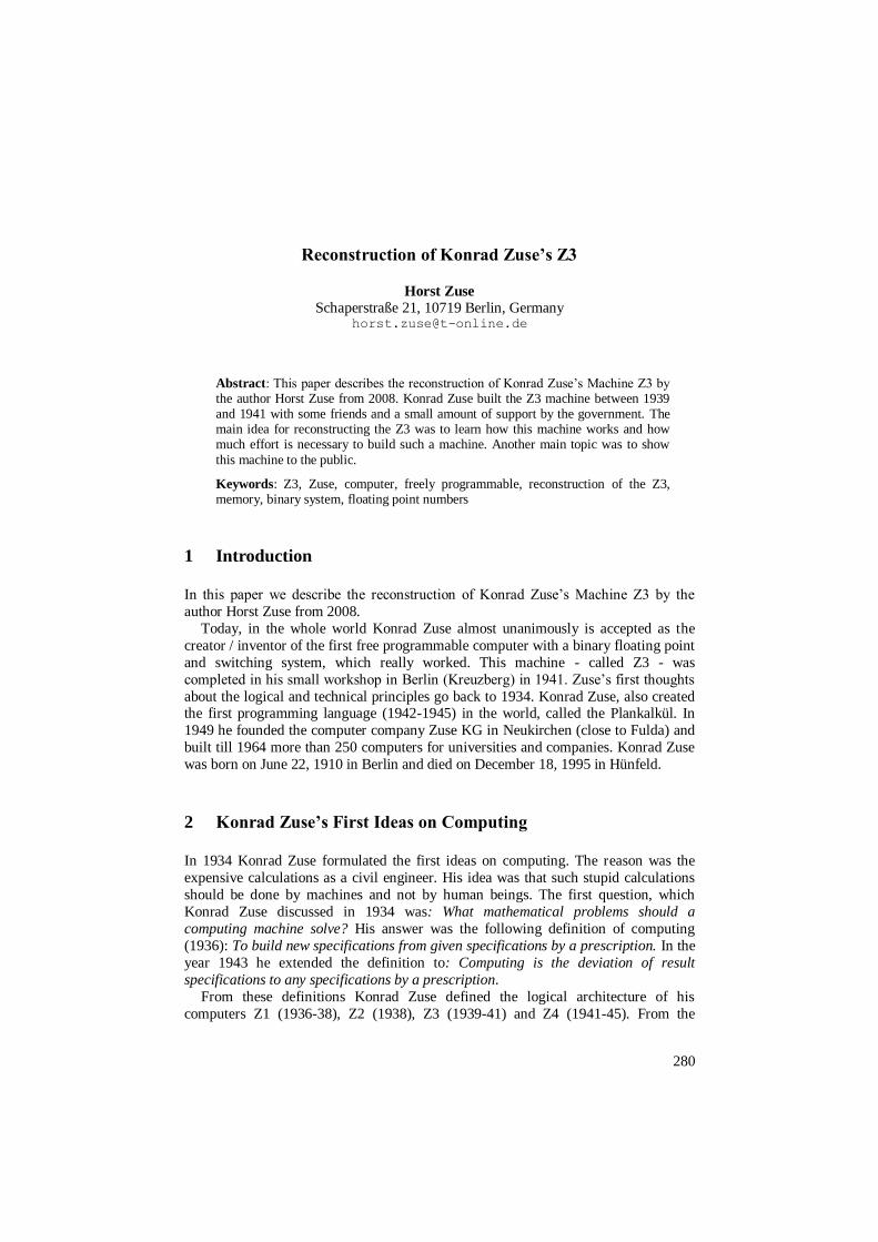
His first machine Z1, which worked on these principles, was constructed from 1936-
1938. It was a machine with a 64 cell (words) memory of 22-bits and the components
as discussed above. The Z1 consisted completely of thin metal sheets, which friends
and he produced with a jigsaw. The clock frequency was around one Hertz. The Z1 was the first freely programmable machine, based on a binary principle, of the world.
Figure 1: Left: The computer Z1 in the living room of his parents in 1938. Right: Building blocks (thin metal sheets) of the Z1.
The Z1 was in many ways a remarkable machine. Konrad Zuse used thin metal
sheets in order to construct this machine. There were no relays in it. The only one
electrical unit was an electrical engine in order to give the clock frequency of one
282
Hertz to the machine. The Z1 was freely programmable via a punch tape and a punch
tape reader. There was a clear separation of the punch tape reader, the control unit for
supervising the whole machine and the execution of the instructions, the arithmetic
unit with the two Registers R1 and R2, the memory with 64 words of 22-bits and the
input and output devices.
2.2.2 Computer Z3
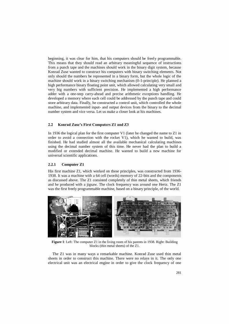
Konrad Zuse built the machine Z3 from 1939 to 1941 in the Methfesselstraße 7 in
Berlin-Kreuzberg with some friends and a small amount of support by the government.
Figure 2: A drawing of the Z3 by Konrad Zuse (the exactly date of this drawing is unclear). The height of the machine is around 2,20m, the width of one cupboard is 1,20m. On the left
side is the arithmetic unit; on the right are both the memory cupboards. In the front the input- and output device and the punch tape reader. 800 relays in the arithmetic unit and 2000 in the
memories.
With the Z3 Konrad Zuse wanted to show, that it is possible to build a reliable
working machine for very complicated arithmetic calculations, which is freely
programmable and is based on a binary floating point number and switching system.
For reliability reasons he used relays for the entire machine.
283
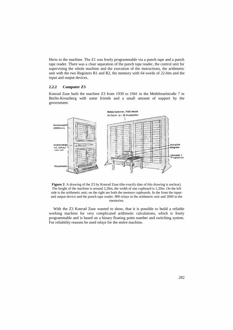
Figure 3: Left: The rebuilt computer Z3 in 1964 with Konrad Zuse. The machine is from the cubical expansion much smaller than the original one. The memory is on the left side (- the
logo Z of the Zuse KG can be seen) and the arithmetic unit with the stepwise relays are on the right side. Left on the front the console with the punch tape reader can be seen. Right: The diary of Konrad Zuse at May 12, 1941: Konrad Zuse presented the original working Z3 to scientists
in Berlin.
2.2.3 Architecture of the Z3
We are showing some technical data of the architecture of the Z3.
Parallel Machine: The Z3 was a parallel working machine. The 22-bits from the
memory to the Register R1 and vice versa were moved in one step (cycle). The same
holds for the binary arithmetic unit, where, among others, two parallel adders
(exponent, mantissa) were used.
Memory: The memory of the Z3 consisted of 64 words of 22-bits. Each word was directly addressable by the instructions Pr z or Ps z, where z is the address in the
range: 64 z 1. For each bit a relay was needed. Floating Point Numbers: Konrad Zuse used floating point numbers.
Instructions: The Z3 disposed of the nine instructions.
Arithmetic Unit and Carry Ahead: The arithmetic unit of the Z3 is Konrad
Zuse’s masterstroke. He reduced all the arithmetic operations to addition or
subtraction. For the realization of the addition (subtraction is an addition of the
complement of one number and the number) Konrad Zuse implemented a special
switch because he wanted to avoid too many cycles for the addition of two binary
floating point numbers. Using the special switch, he could reduce the addition from at
least 14 cycles with a serial addition down to three cycles with a parallel addition.
Although there were only five instructions (Ls1, Ls2, Lm, Li, and Lw) for arithmetic
operations, some more operations were implemented which could be called from the input device. He also simplified the execution of the arithmetic operations with micro-
sequences controlled by stepwise relays.
284
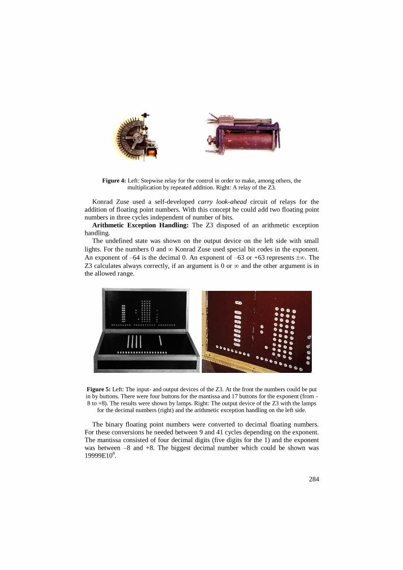
Figure 4: Left: Stepwise relay for the control in order to make, among others, the multiplication by repeated addition. Right: A relay of the Z3.
Konrad Zuse used a self-developed carry look-ahead circuit of relays for the
addition of floating point numbers. With this concept he could add two floating point
numbers in three cycles independent of number of bits.
Arithmetic Exception Handling: The Z3 disposed of an arithmetic exception
handling.
The undefined state was shown on the output device on the left side with small
lights. For the numbers 0 and Konrad Zuse used special bit codes in the exponent.
An exponent of –64 is the decimal 0. An exponent of –63 or +63 represents . The
Z3 calculates always correctly, if an argument is 0 or and the other argument is in the allowed range.
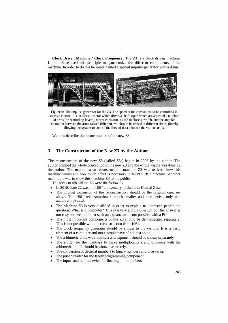
Figure 5: Left: The input- and output devices of the Z3. At the front the numbers could be put in by buttons. There were four buttons for the mantissa and 17 buttons for the exponent (from -8 to +8). The results were shown by lamps. Right: The output device of the Z3 with the lamps
for the decimal numbers (right) and the arithmetic exception handling on the left side.
The binary floating point numbers were converted to decimal floating numbers.
For these conversions he needed between 9 and 41 cycles depending on the exponent.
The mantissa consisted of four decimal digits (five digits for the 1) and the exponent
was between –8 and +8. The biggest decimal number which could be shown was
19999E108.
285
Clock Driven Machine / Clock Frequency: The Z3 is a clock driven machine.
Konrad Zuse used this principle to synchronize the different components of the
machine. In order to do this he implemented a special impulse generator with a drum.
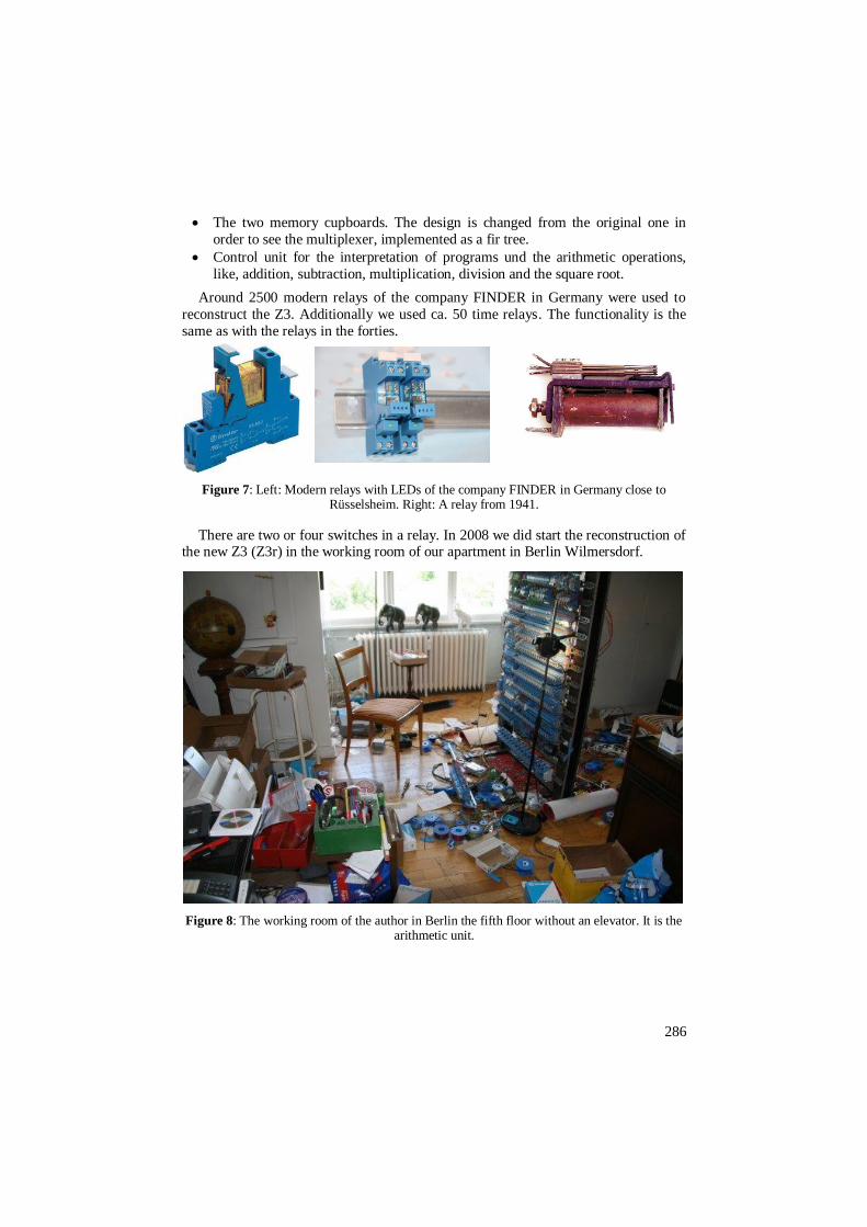
Figure 6: The impulse generator for the Z3. The speed of the capstan could be controlled in steps (5 Hertz). It is an electric motor which drives a shaft, upon which are attached a number
of arms (or protruding levers), where each arm is used to close a switch, and the angular separation between the arms caused different switches to be closed at different times, thereby
allowing the system to control the flow of data between the various units.
We now describe the reconstruction of the new Z3.
3 The Construction of the New Z3 by the Author
The reconstruction of the new Z3 (called Z3r) begun in 2008 by the author. The
author planned the whole conception of the new Z3 and the whole wiring was done by
the author. The main idea to reconstruct the machine Z3 was to learn how this
machine works and how much effort is necessary to build such a machine. Another
main topic was to show this machine Z3 to the public.
The ideas to rebuild the Z3 were the following:
In 2010, June 22 was the 100th anniversary of the birth Konrad Zuse.
The cubical expansion of the reconstruction should be the original one, see
above. The 1961 reconstruction is much smaller and there exists only one
memory cupboard.
The Machine Z3 is very qualified in order to explain to interested people the question: What is a computer? This is a very simple question but the answer is
not easy and we think that such an explanation is not possible with a PC
The most important components of the Z3 should be demonstrated separately.
This is not possible with the reconstruction from 1961.
The clock frequency generator should by shown to the visitors. It is a basic
element of a computer and most people have of no idea about it.
The arithmetic units with mantissa and exponent should be shown separately.
The shifter for the mantissa to make multiplications and divisions with the
arithmetic unit. It should be shown separately.
The conversion of decimal numbers to binary numbers and vice versa.
The punch reader for the freely programming component.
The input- and output device for floating point numbers.
286
The two memory cupboards. The design is changed from the original one in
order to see the multiplexer, implemented as a fir tree.
Control unit for the interpretation of programs und the arithmetic operations,
like, addition, subtraction, multiplication, division and the square root.
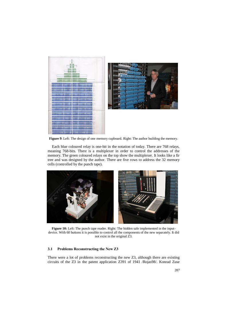
Around 2500 modern relays of the company FINDER in Germany were used to
reconstruct the Z3. Additionally we used ca. 50 time relays. The functionality is the
same as with the relays in the forties.
Figure 7: Left: Modern relays with LEDs of the company FINDER in Germany close to Rüsselsheim. Right: A relay from 1941.
There are two or four switches in a relay. In 2008 we did start the reconstruction of the new Z3 (Z3r) in the working room of our apartment in Berlin Wilmersdorf.
Figure 8: The working room of the author in Berlin the fifth floor without an elevator. It is the arithmetic unit.
287
Figure 9: Left: The design of one memory cupboard. Right: The author building the memory.
Each blue coloured relay is one-bit in the notation of today. There are 768 relays,
meaning 768-bits. There is a multiplexer in order to control the addresses of the
memory. The green coloured relays on the top show the multiplexer. It looks like a fir
tree and was designed by the author. There are five rows to address the 32 memory
cells (controlled by the punch tape).
Figure 10: Left: The punch tape reader. Right: The hidden safe implemented in the input-device. With 60 buttons it is possible to control all the components of the new separately. It did
not exist in the original Z3.
3.1 Problems Reconstructing the New Z3
There were a lot of problems reconstructing the new Z3, although there are existing
circuits of the Z3 in the patent application Z391 of 1941 /Rojas98/. Konrad Zuse
288
never got this patent; it was rejected in 1967 because of lack of amount of invention.
However, it was necessary to modify many circuits. The reasons were among others
the following:
The clock frequency of the new Z3 is realized with special frequency relays of
FINDER. The original Z3 had an impulse generator with a drum.
The control unit of the new Z3 is realized with time relays. It was not possible to
get enough stepwise relays.
Electronic stepwise relays were used instead of mechanical ones.
The next image shows the new Z3 in 2011 in the Heinz Nixdorf Museum Forum in
Paderborn.
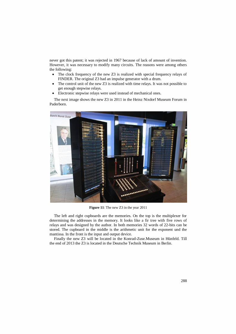
Figure 11: The new Z3 in the year 2011
The left and right cupboards are the memories. On the top is the multiplexer for
determining the addresses in the memory. It looks like a fir tree with five rows of
relays and was designed by the author. In both memories 32 words of 22-bits can be
stored. The cupboard in the middle is the arithmetic unit for the exponent und the
mantissa. In the front is the input and output device.
Finally the new Z3 will be located in the Konrad-Zuse.Museum in Hünfeld. Till
the end of 2013 the Z3 is located in the Deutsche Technik Museum in Berlin.
289
4 Who Supported the Reconstruction of the Z3
The reconstruction of the new Z3 was very complex. It was much more work than
the author and the supporters believed, it was really a hard job. The work was very
often interrupted by presentations by the author about history of computing from 2008
till today. The sponsors and supporters of the project came from the area of Hünfeld
close to Fulda. Supporters were a lot of companies in Germany.
Sponsors
Förderung Stiftung der Sparkasse Fulda.
Zuschuss Land Hessen: Hessisches Ministerium f. Wissenschaft und Kunst.
Dr. Tim Olbricht aus Hünfeld.
Eigenanteil Stiftung Stadt- und Kreisgeschichtliches: Museum Hünfeld mit
Konrad-Zuse-Museum.
Supporters of the Projekt
Fa. Dux Elektrokontakt GmbH, 04303 Leipzig: Switches.
Fa. Eltec Engineering GmbH, 10587 Berlin: Mechanical planning.
Fa. Finder GmbH, 65468 Trebur-Astheim: Relays.
Fa. Erwin Krug & Söhne GmbH Co KG, 14199 Berlin: Cupboards
Fa. Harting Deutschland GmbH Co KG, 32381 Minden: Connections.
Fa. Wago Kontakttechnik GmbH & Co KG, 32385 Minden: Connexions.
Kanzlei Hübner & Dr. Körting, 10623 Berlin: Protection of
registered design.
Fa. ELSAME GmbH - Forckenbeckstrasse 9-13, 14199 Berlin: Location of the
Z3 in 2011 for further developments.
Literature
/ROJA98/Rojas Raul (Editor): Die Rechenmaschinen von Konrad Zuse, Springer
Verlag, 1998.
This is a detailed analysis of a Konrad Zuse’s machines Z1 and Z3 with many new
details, also the drawing in the patent application from 1941 are shown. It also contains the report of the fight of Konrad Zuse for his patents from 1938 till 1967.
Konrad Zuse lost this fight in 1967 because of lack of amount of invention.