Embed Size (px)
Citation preview

Engineering Management Consulting
Moss Landing Tower Collapse
Root Cause Analysis
1600474.000 - 4172
Moss Landing Tower Collapse
Root Cause Analysis
Prepared for
Pacific Gas & Electric
6111 Bollinger Canyon Road
San Ramon, CA 94583
Prepared by
Exponent
475 14th
Street, Suite 400
Oakland, CA 94612
April 4, 2016
Exponent, Inc.
1600474.000 - 4172
ii
Contents
Page
List of Figures iv
List of Tables v
Limitations vi
Executive Summary vii
1. Background 1
1.1 Tower Design and Event Description 1
1.2 Failure Analysis Findings 2
2. Problem Statement 7
3. Root Cause Analysis Approach 8
4. Data Collection and Analysis 10
5. Observations and Findings 12
5.1 Sequence of Events 12
5.2 Observations and Findings 14
6. Causal Analysis 19
6.1 Causal Analysis 19
6.2 Root and Contributing Causes 21
7. Recommended Corrective Actions 23
8. Extent of Condition 24
9. Conclusions 25
10. References 26
1600474.000 - 4172
iii
Appendix A Interview List
Appendix B Event Timeline and Process Comparison
Appendix C Findings Description and Evidence
Appendix D Event and Causal Factors Chart
Appendix E Causal Factors Analysis Chart
1600474.000 - 4172
iv
List of Figures
Page
Figure 1: Moss Landing Tower Collapse Site Photo 2
Figure 2: Tower Foundation Layout and Conductor Location 4
Figure 3: Stub Angle – Lower Tower Leg Orientation (for illustrative purposes only) 6
Figure 4: Prevention of Unwanted Events 8
Figure 5: Heel Batter Designation from Drawing 313438 15
Figure 6: Stub Batter Angles from Rec. 621915 16
Figure 7: Human Error Classification 19

1600474.000 - 4172
v
List of Tables
Page
Table 1: Recommended Corrective Actions 23
1600474.000 - 4172
vi
Limitations
At the request of Pacific Gas & Electric Company (PG&E), Exponent conducted a root cause
assessment of electric transmission tower collapse on October 18, 2015 resulting in significant
equipment and structure damage as well as customer outages. Exponent has investigated
specific issues relevant to the incident as requested by PG&E. The scope of services performed
during this investigation, as well as our findings as described herein, may not adequately
address the needs of other users and any re-use of this report, conclusions, or recommendations
presented herein are at the sole risk of the user.
The findings presented herein are made to a reasonable degree of engineering and scientific
certainty based on observations and information available at the time of the investigation. This
report may be supplemented to expand or modify our findings based on additional work or
review of additional information. Thus, if new data become available or there are perceived
omissions or misstatements in this report, we ask that they be brought to our attention as soon as
possible so that we have the opportunity to fully address them.
1600474.000 - 4172
vii
Executive Summary
On October 18, 2015, a PG&E electric transmission tower located in Moss Landing, CA
collapsed. The tower was a 124-foot tall, steel lattice, overhead transmission tower of a type
designated by PG&E as G95-DE with a 32.5-ft extension. The tower supported two circuits
(Metcalf – Moss Landing 1 and Metcalf – Moss Landing 2), each composed of three 954
KCMIL Cardinal ACSS conductors (1.196” diameter) spanning 252 feet to the east, and three
bundled (paired) 1113 KCMIL Marigold AAC conductors (1.216” diameter) dropping to the
substation to the south1,2. The tower was of bolted steel construction whose basic design is
shown on PG&E Drawings 403912 (Rev. 8) and Rec. 622028.
PG&E retained Exponent Failure Analysis Associates (Exponent) to investigate the direct and
root cause(s) of the accident, and in particular, to evaluate the tower design and material
properties for possible contribution to the collapse. Exponent prepared two reports for this
investigation: a structural and metallurgical failure analysis report2 and this report to identify the
root cause. Based on the failure analysis, Exponent2 identified two principal findings relative to
the tower collapse:
Based on measurements made of the foundations after the accident, the stub angles were
not oriented correctly at the time of construction. Rather than being tilted to match the
sloped tower legs, the stub angles were installed with insufficient batter (angle);
therefore, causing a misalignment of the stub angles and lower tower legs. When the
bolts were tightened to bring these components together, the out-of-alignment
configuration produced bending moments in the stub angles which exceeded the stress
limits in the stub angle material.
Based on metallurgical examination and testing of steel specimens of the stub angles
recovered from the site, the steel met the mechanical and chemical requirements for
ASTM A572 Grade 50 at the time of the specification and purchase. The accident
fracture surfaces and subsequent testing indicates that this steel is more brittle than
desirable for the subject tower application. However, the tower would not have
collapsed if the stub angles and lower legs were aligned as-designed. PG&E is in the
process of updating its material specifications to include fracture toughness
requirements.
1 Drawing No. 076274, Rev. 6, Page 10
2 Reference 1: Exponent Failure Analysis Report
1600474.000 - 4172
viii
Based on the results of the failure analysis and a review of the available documentation,
Exponent defined the problem statement for the root cause analysis as:
“On October 18, 2015, a 124-foot electric transmission steel lattice tower collapsed in
Moss Landing, California, due to the incorrect installation of the footing stub angles
during foundation construction, resulting in the collapse of the tower and damage to
adjacent structures.”
From the findings identified, the tower collapse event was initiated by the incorrect settings of
the stub angle due to a human error in reading the drawing heel batter; and the subsequent
communication of this incorrect heel batter to the crew for use in setting the stub angles3.
Human errors may occur for a variety of reasons, but work processes and programs are put in
place to prevent human errors from having significant consequences. Typical human error
defenses (barriers to prevent human error) include training, procedures, clear documents and
communication, and independent verification. Since the human error relative to the stub angle
alignment with the tower legs resulted in a significant occurrence, the causal analysis includes a
review of these barriers and their performance and contribution to the incident.
Based on the causal evaluation, the root and contributing causes of the incident are listed below.
The root cause is based on determining whether eliminating the cause would have prevented or
significantly reduced the probability of the incident, and whether eliminating the cause is under
the control of management. Contributing causes are those that may contribute to preventing the
event.
Root Cause: Inadequate process to ensure that critical parameters (dimensions and/or
steps) of the transmission towers are constructed as designed: The verification
methodology to ensure that design information from the tower drawings is correctly
transferred to the construction installation process should be improved. There is no
formal requirement to verify the take-offs from the drawings. Since the stub angle
inclination is a key dimension for validating the tower design, a defined means to
determine and confirm this dimension (as well as other key parameters) is required.
Contributing Cause 1: Inadequate process design relative to training requirements for
tower drawings for transfer of design-related information to the construction crews:
The tower construction utilizes general drawings and not site specific drawings. There is
no formal training that provides the construction crew with information on what
drawings to review and how to interpret these drawings. Also, the key parameters that
govern the design are not communicated except through informal on-the-job (OJT)
training. Formal training provides a basis for understanding requirements and gaining
necessary information on significant design considerations as impacted by construction
3 Since the identification of the human error occurred approximately nine months after the stub angle setting, it is
expected that the recollection of specific events from interviews may be imprecise.
1600474.000 - 4172
ix
activities. Also, tower erection is not performed frequently and the use of OJT
exclusively may no longer be sufficient.
Contributing Cause 2: Inadequate maintenance (update) of drawings relative to
legacy tower drawings may not reflect the current needs of crews who perform the
tower installations on an infrequent basis: The tower drawings are very dated and last
updated in the 1960’s. Therefore, this causes the potential for error in reading the
drawings due to legibility issues, as well as missing or confusing information.
Contributing Cause 3: Inadequate process design relative to training requirements for
tower drawings on dimensional tolerances and potential field issues: This cause is
similar to Contributing Cause 1, except that it relates to the field identification of
potential issues. There is no formal guidance provided to the crews relative to fit-up
tolerances on critical dimensional measurements, and other field observations that may
indicate a problem.
Recommended corrective actions are identified and included in Section 7. This Executive
Summary does not contain all of Exponent’s technical evaluations, analyses, conclusions and
recommendations. Hence, the main body of this report is, at all times, the controlling document.
1600474.000 - 4172
1
1. Background
1.1 Tower Design and Event Description
On October 18, 2015, a PG&E electric transmission tower located in Moss Landing, CA
collapsed. The tower was a 124-foot tall, steel lattice, overhead transmission tower of a type
designated by PG&E as G95-DE with a 32.5-ft extension. The tower supported two circuits
(Metcalf – Moss Landing 1 and Metcalf – Moss Landing 2), each composed of three 954
KCMIL Cardinal ACSS conductors (1.196” diameter) spanning 252 feet to the east, and three
bundled (paired) 1113 KCMIL Marigold AAC conductors (1.216” diameter) dropping to the
substation to the south4,5. The tower was of bolted steel construction whose basic design is
shown on PG&E Drawings 403912 (Rev. 8) and Rec. 622028.
The tower was constructed in the following sequence:
March 18-19, 2015: The four concrete foundation piers (with embedded and protruding
stub angles) were set on March 18 and poured on March 19.
April 6-8, 2015: Construction of the base (lower tower extensions) occurred at this time.
The tower was constructed piecewise by first erecting a 17.5-ft extension (lower tower
legs, diagonal lacing, and horizontals), and then a 15-ft extension to complete the base.
September 8, 2015: After the base was erected, the remaining tower structure, which had
been pre-assembled on site, was placed atop the brace with a crane after clearances were
received.
September 12, 2015: The wire transfer operations were conducted for Metcalf-Moss
Landing Circuit 1.
October 10, 2015: The wire transfer operations were conducted for Metcalf-Moss
Landing Circuit 2.6
4 Drawing No. 076274, Rev. 6, Sheet 10
5 Reference 1: Exponent Failure Analysis Report
6 Detailed tower information from Reference 1
1600474.000 - 4172
2
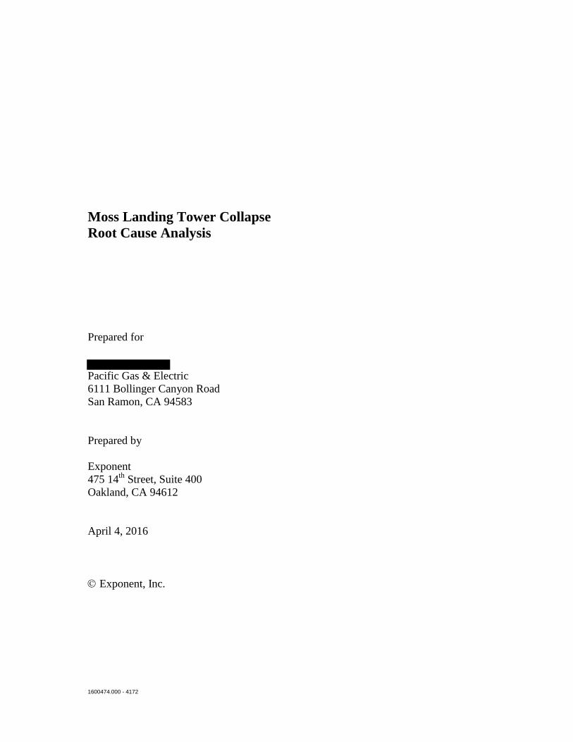
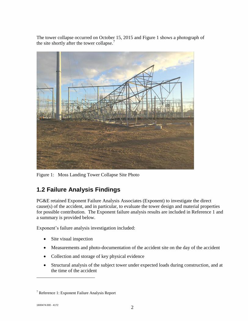
The tower collapse occurred on October 15, 2015 and Figure 1 shows a photograph of
the site shortly after the tower collapse.7
Figure 1: Moss Landing Tower Collapse Site Photo
1.2 Failure Analysis Findings
PG&E retained Exponent Failure Analysis Associates (Exponent) to investigate the direct
cause(s) of the accident, and in particular, to evaluate the tower design and material properties
for possible contribution. The Exponent failure analysis results are included in Reference 1 and
a summary is provided below.
Exponent’s failure analysis investigation included:
Site visual inspection
Measurements and photo-documentation of the accident site on the day of the accident
Collection and storage of key physical evidence
Structural analysis of the subject tower under expected loads during construction, and at
the time of the accident
7 Reference 1: Exponent Failure Analysis Report
1600474.000 - 4172
3
Review of design documents and summaries of the design and construction process for
this tower
Verification of selected tower design loads and member sizes as they relate to the
accident
Metallurgical analysis
Mechanical properties testing of steel specimens recovered from the accident site, as well
as exemplar material provided by PG&E
Finite element-based stress analysis
Linear-elastic fracture mechanics analysis
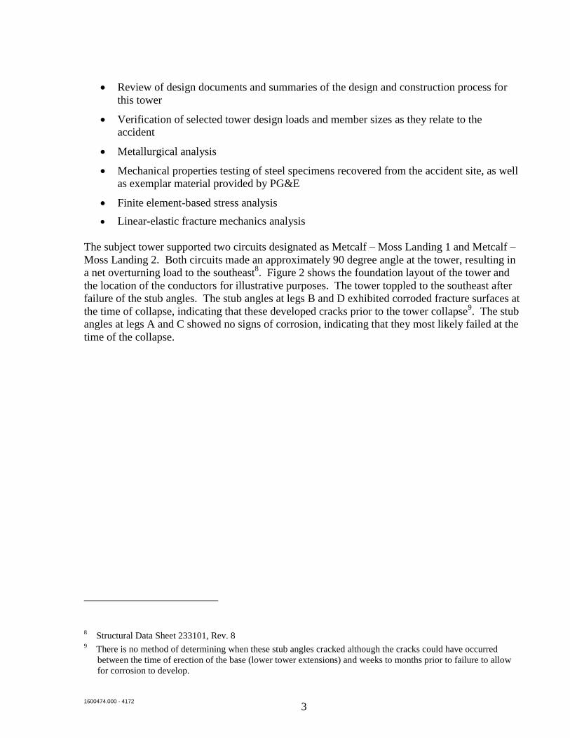
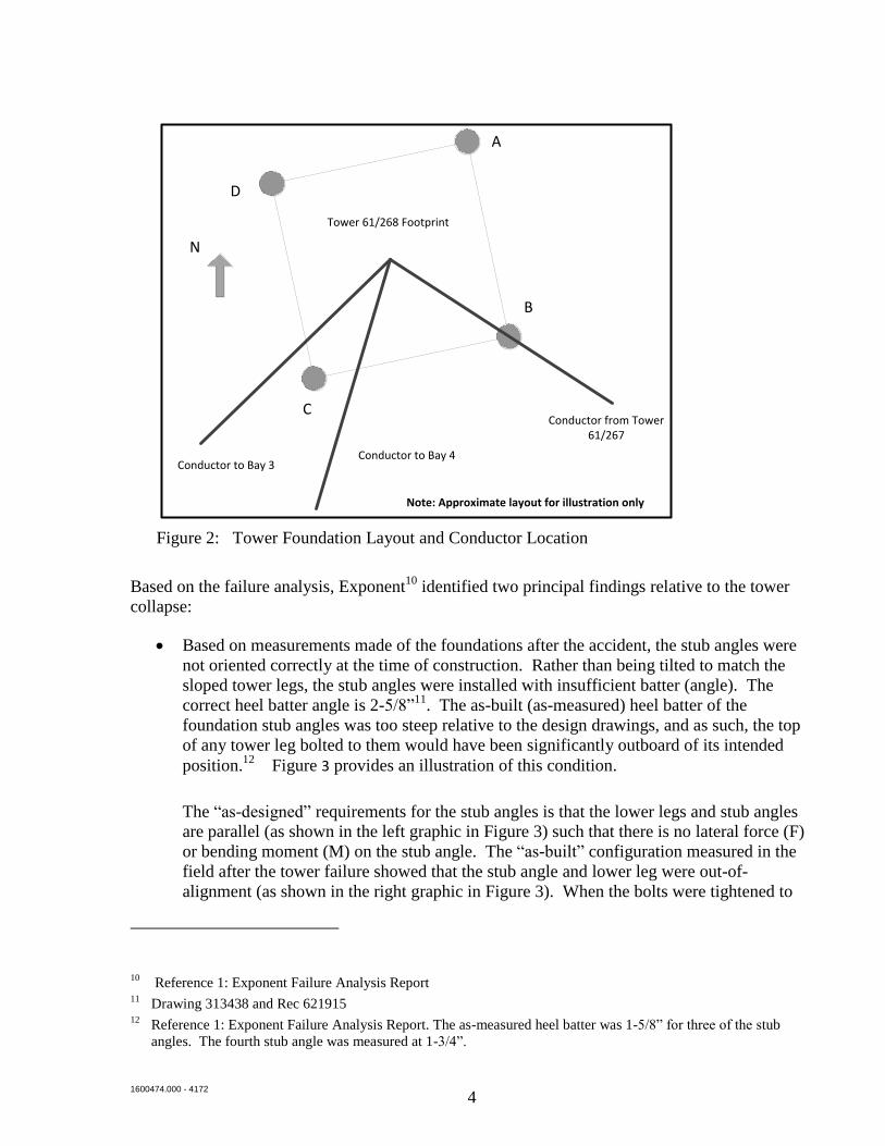
The subject tower supported two circuits designated as Metcalf – Moss Landing 1 and Metcalf –
Moss Landing 2. Both circuits made an approximately 90 degree angle at the tower, resulting in
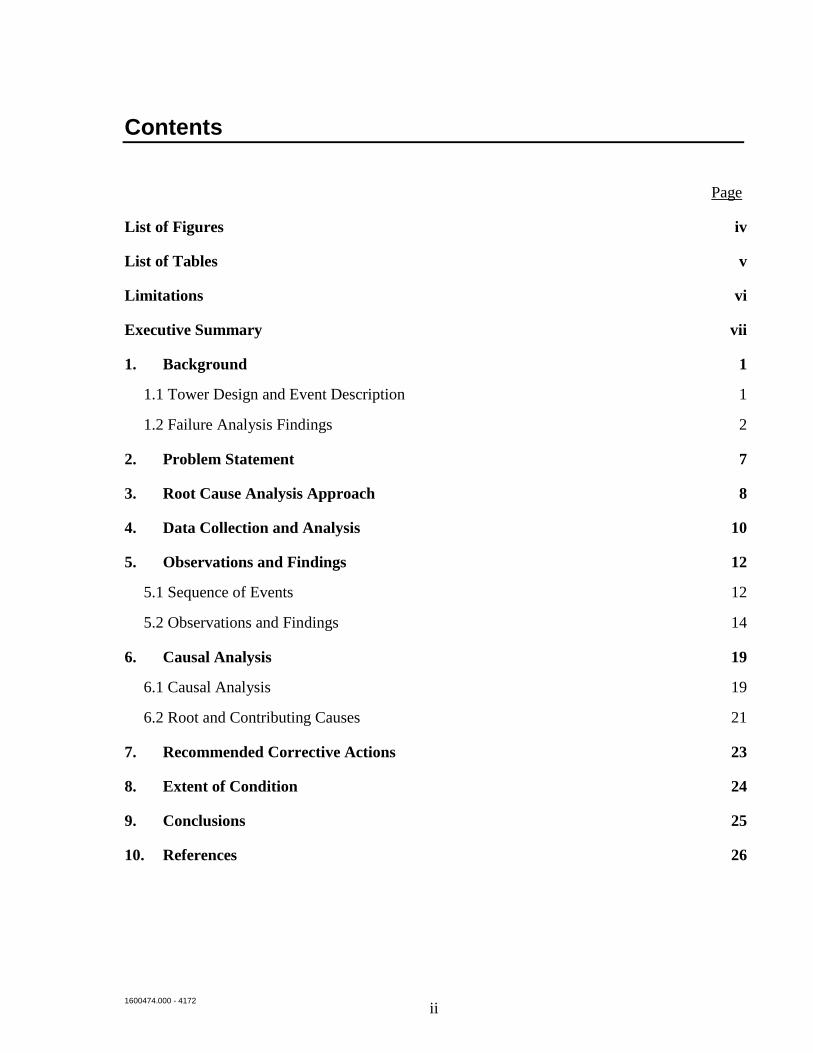
a net overturning load to the southeast8. Figure 2 shows the foundation layout of the tower and
the location of the conductors for illustrative purposes. The tower toppled to the southeast after
failure of the stub angles. The stub angles at legs B and D exhibited corroded fracture surfaces at
the time of collapse, indicating that these developed cracks prior to the tower collapse9. The stub
angles at legs A and C showed no signs of corrosion, indicating that they most likely failed at the
time of the collapse.
8 Structural Data Sheet 233101, Rev. 8
9 There is no method of determining when these stub angles cracked although the cracks could have occurred
between the time of erection of the base (lower tower extensions) and weeks to months prior to failure to allow
for corrosion to develop.
1600474.000 - 4172
4
Figure 2: Tower Foundation Layout and Conductor Location
Based on the failure analysis, Exponent10
identified two principal findings relative to the tower
collapse:
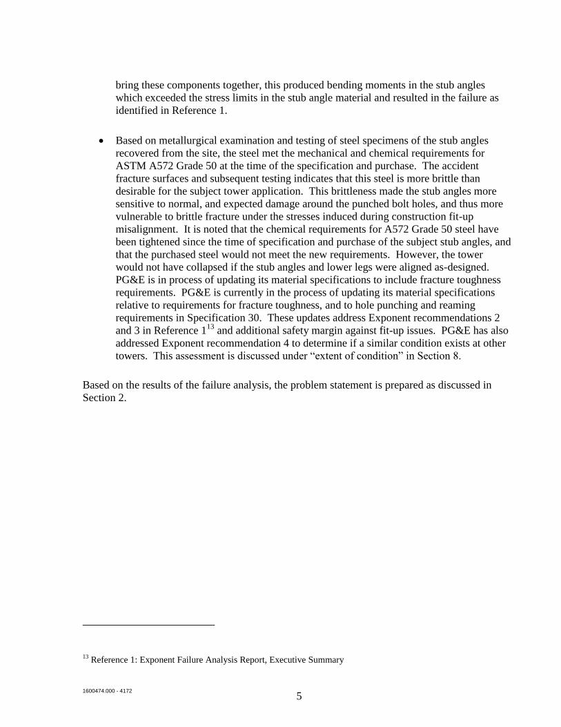
Based on measurements made of the foundations after the accident, the stub angles were
not oriented correctly at the time of construction. Rather than being tilted to match the
sloped tower legs, the stub angles were installed with insufficient batter (angle). The
correct heel batter angle is 2-5/8”11
. The as-built (as-measured) heel batter of the
foundation stub angles was too steep relative to the design drawings, and as such, the top
of any tower leg bolted to them would have been significantly outboard of its intended
position.12
Figure 3 provides an illustration of this condition.
The “as-designed” requirements for the stub angles is that the lower legs and stub angles
are parallel (as shown in the left graphic in Figure 3) such that there is no lateral force (F)
or bending moment (M) on the stub angle. The “as-built” configuration measured in the
field after the tower failure showed that the stub angle and lower leg were out-of-
alignment (as shown in the right graphic in Figure 3). When the bolts were tightened to
10 Reference 1: Exponent Failure Analysis Report
11 Drawing 313438 and Rec 621915
12 Reference 1: Exponent Failure Analysis Report. The as-measured heel batter was 1-5/8” for three of the stub
angles. The fourth stub angle was measured at 1-3/4”.
A
D
C
B
N
Tower 61/268 Footprint
Conductor from Tower 61/267
Conductor to Bay 4Conductor to Bay 3
Note: Approximate layout for illustration only
1600474.000 - 4172
5
bring these components together, this produced bending moments in the stub angles
which exceeded the stress limits in the stub angle material and resulted in the failure as
identified in Reference 1.
Based on metallurgical examination and testing of steel specimens of the stub angles
recovered from the site, the steel met the mechanical and chemical requirements for
ASTM A572 Grade 50 at the time of the specification and purchase. The accident
fracture surfaces and subsequent testing indicates that this steel is more brittle than
desirable for the subject tower application. This brittleness made the stub angles more
sensitive to normal, and expected damage around the punched bolt holes, and thus more
vulnerable to brittle fracture under the stresses induced during construction fit-up
misalignment. It is noted that the chemical requirements for A572 Grade 50 steel have
been tightened since the time of specification and purchase of the subject stub angles, and
that the purchased steel would not meet the new requirements. However, the tower
would not have collapsed if the stub angles and lower legs were aligned as-designed.
PG&E is in process of updating its material specifications to include fracture toughness
requirements. PG&E is currently in the process of updating its material specifications
relative to requirements for fracture toughness, and to hole punching and reaming
requirements in Specification 30. These updates address Exponent recommendations 2
and 3 in Reference 113
and additional safety margin against fit-up issues. PG&E has also
addressed Exponent recommendation 4 to determine if a similar condition exists at other
towers. This assessment is discussed under “extent of condition” in Section 8.
Based on the results of the failure analysis, the problem statement is prepared as discussed in
Section 2.
13 Reference 1: Exponent Failure Analysis Report, Executive Summary
1600474.000 - 4172
6
Figure 3: Stub Angle – Lower Tower Leg Orientation (for illustrative purposes only)
12"
2-5/8" per design
1-5/8" As-measured (Stubs A, B, D) and
1-3/4” (Stub C)
F
M
F = force required to align tighten bolts to connect stub angle and lower leg
M = bending moment resulting from aligning lower leg with stub angle
AS-DESIGNED AS-BUILT
Lower extension leg
Concrete footing
Stub angle 12"
1600474.000 - 4172
7
2. Problem Statement
The problem statement provides the focus of the root cause analysis to ensure that the
appropriate issues are addressed. Based on the results of the failure analysis (reference 1), and a
review of the available documentation, Exponent defined the problem statement for the root
cause analysis as:
“On October 18, 2015, a 124-foot electric transmission steel lattice tower collapsed in Moss
Landing, California, due to the incorrect installation of the footing stub angles during
foundation construction, resulting in the collapse of the tower and damage to adjacent
structures.”
1600474.000 - 4172
8
3. Root Cause Analysis Approach
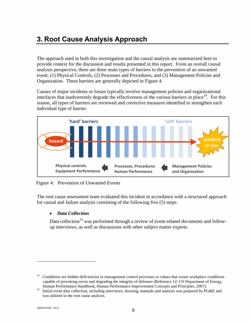
The approach used in both this investigation and the causal analysis are summarized here to
provide context for the discussion and results presented in this report. From an overall causal
analysis perspective, there are three main types of barriers to the prevention of an unwanted
event; (1) Physical Controls, (2) Processes and Procedures, and (3) Management Policies and
Organization. These barriers are generally depicted in Figure 4.
Causes of major incidents or losses typically involve management policies and organizational
interfaces that inadvertently degrade the effectiveness of the various barriers in place14
. For this
reason, all types of barriers are reviewed and corrective measures identified to strengthen each
individual type of barrier.
Figure 4: Prevention of Unwanted Events
The root cause assessment team evaluated this incident in accordance with a structured approach
for causal and failure analysis consisting of the following five (5) steps:
Data Collection
Data collection15
was performed through a review of event-related documents and follow-
up interviews, as well as discussions with other subject matter experts.
14 Conditions are hidden deficiencies in management control processes or values that create workplace conditions
capable of provoking errors and degrading the integrity of defenses (Reference 12: US Department of Energy,
Human Performance Handbook, Human Performance Improvement Concepts and Principles, 2007). 15
Initial event data collection, including interviews, drawing, manuals and analysis was prepared by PG&E and
was utilized in the root cause analysis.
‘hard’ barriers ‘soft’ barriers
accident or loss
hazard
Processes, ProceduresHuman Performance
Management Policiesand Organization
Physical controlsEquipment Performance
1600474.000 - 4172
9
Reconstruction of Problem Scenarios
As a result of the data collection activities and the direct cause analysis (Reference 1),
a sequence of events was developed around specific activities for use in evaluating
the incident.
Performance of Causal Analysis
The causal analysis was performed in a structured sequence of steps that led to
identification of the root and contributing causes. The cause analysis tools used in
this investigation were:
a. Events and Causal Factors Analysis (ECFA) – This tool is used to identify
potential systemic incident causes (i.e., management policies and
organization) for each initiating event. It involves repeatedly asking why the
event or pre-condition existed in order to identify the underlying causes. This
tool was used for the primary causal analysis.
b. Causal Factor Unit Analysis – This step involved a detailed evaluation of each
cause identified in the ECFA, and was used to determine the root cause(s) of
the incident. It involves assessing the degree to which each condition
contributing to the incident is within management’s control to change, and
whether its removal would have prevented the occurrence of the problem.
Those causes which meet these criteria were determined to be the root
cause(s) of the incident.
The outcome of the above causal analyses was the identification of the root and
contributing causes. This information formed the basis for assessing lessons learned
and corrective actions.
Review for Extent of Condition
An outcome of the causal analysis is to identify the potential for the problem or cause
to exist elsewhere.
Development of Recommended Corrective Actions
The desired outcome of the causal analysis is to identify recommended corrective
actions to prevent recurrence of the problem, and to identify lessons learned.
Effective corrective actions are those that address the causes, are implementable by
the organization, are cost effective and are consistent with company business goals
and strategies.
1600474.000 - 4172
10
4. Data Collection and Analysis
The data collection and analysis was performed primarily through review of records provided by
PG&E, as well as supplemental interviews with project participants and subject matter experts.
The kick-off meeting for the root cause investigation was held on January 27, 2016. Since the
incident’s occurrence in October 2015, PG&E has performed interviews, data collection and
analysis. Exponent has built on that information for use in this analysis. The principal sources
of information used in this analysis are:
Documentation (see Section 10 References for a list of documents reviewed)
Interviews (see Appendix A for list of interviewees)16
The timeline for the incident was developed from the time of “submittal of the job package to
construction” through the “incident”. This time frame provides for a complete review of actions,
processes, and requirements leading up to the tower installation job and the events of October 18,
2015. The data collection and analysis is performed to develop an event timeline (or sequence of
events) and to compare the job’s as-required processes to the as-performed processes in order to
identify gaps and actions that may not be in accordance with PG&E expectations. These gaps
and actions are the starting point of the causal analysis.
The key activities reviewed in the data collection are:
Job package completeness
Construction foundation planning
Foundation set-up and prep
Setting and installation of the stub angles
Verification of stub angle placement
Installation of lower tower extensions
The results of the data collection are provided in the following:
Sequence of events (see Appendix B)
Findings descriptions and evidence chart (see Appendix C)
16 Since the identification of the human error occurred approximately nine months after the stub angle setting, it is
expected that the recollection of specific events from interviews may be imprecise.
1600474.000 - 4172
11
The timeline in Appendix B provides a detailed description of the timeline and process
comparison; and identifies the gaps and actions that may not have been performed according to
PG&E expectations. These findings are described in Section 5 and Appendix C.
1600474.000 - 4172
12
5. Observations and Findings
Background information is presented in this section to describe the sequence of events and the
findings and observations from the data analysis that are the basis for initiating the causal
analysis.
5.1 Sequence of Events
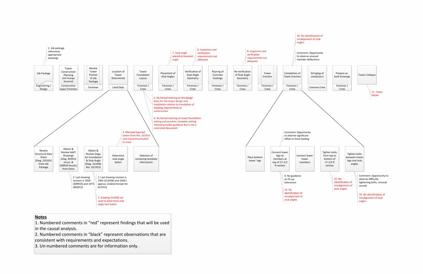
The reconstruction of the problem scenario is described in the sequence of events as shown in the
chart in Appendix B. The sequence of events is described for the tower design and installation.
The key activities defined for the tower design and installation are:
Engineering and design is performed and a job package is created and provided to
construction17
. The tower design is based on existing drawings for the G95 tower type.
The selection of the crew for the tower installation is made by the construction
supervisor18
. The crew foreman and crew lead have prior experience with tower
construction. However, this is the first G95 tower installation that the crew foreman has
led.19
While experience with G95 towers was limited, the crew had tower experience,
and the construction process for the tower and foundation was performed as intended.
The tower installation project is reviewed by the supervisor and crew foreman and
scheduled through the project manager.19
The crew foreman reviewed the job package (structural data sheets and selected
drawings) and assigned tasks to the crew (including communicating the stub angle heel
batter). The crew foreman’s recollection was that he incorrectly communicated the face
batter (1-7/8” per 12”) as the heel batter (correct 2-5/8” per 12”) to the crew based on an
incorrect reading of the drawing (Rec. 621915).19
However, the actual heel batter from
the field measurements was 1-5/8” for 3 stubs and 1-3/4” for the fourth batter (see Figure
3). There is no procedure or requirement that specifies the independent check of the stub
setting dimensions obtained from the drawing, prior to the initiation of field construction
activities.20
17 Reference 2: Job Package
18 Interviews with construction staff and supervisor
19 Interviews with crew foreman
20 Mitigation of operator mistakes (cognitive perception or interpretation malfunction) often require external
monitoring/checking from qualified, experienced, and independent personnel due to the perpetrator having
limited clues there is a problem (Reference 13: Bea, R.G. Human & Organizational Factors: Quality &
Reliability of Engineered Systems, Volume 1. 2008).
1600474.000 - 4172
13
The crew performed the tasks of locating the tower footing locations; placing the stub
angles; and completing the concrete pour to establish the tower footings. The crew
followed appropriate procedures as identified in the Template Setting Manual. [Note that
the site surveys after the event and during the failure analysis indicated that the stub
angles were positioned to the incorrect heel batter angle, communicated by the
foreman.21
]
The crew performed a series of verification activities at the location, during setting and
concrete pour activities for the stub angles and footings. These activities are identified in
the Template Setting Manual and include the following:
o Verification of stub angle batter and alignment within the footprint of the footings
through use of measurement tools (transit, plumb bobs, angle measuring tools,
tape measures), that monitor stub angle setting during setting of individual stub
angles, after completing all stub angle settings, and during the concrete pour. The
dimensions taken off the drawing by the foreman and verbally communicated to
the crew, is the basis for each verification step performed.
o Additional measurements are taken between the stub angles and diagonally across
the foundation footprint.
o Height measurements are also taken at the tops of the stub angles to ensure that
the foundation is appropriate to accept the lower tower extensions.
Through the interviews with the crew foreman and crew lead, the measurements were all
at the approximate requirements of the drawings. Length measurements between
footings were reported as within 5/8”22
. There is no guidance provided for tolerances on
the footing measurements.
The crew erected the tower base (17-1/2 foot base extension), and indicated that there
was no significant issue with completion of this activity, and that it was similar to other
tower projects. There was no identification of the misalignment of the stub angles.23
The crew completed the remaining upper tower erection.
The linemen installed the conductors.
The construction crew completed the as-built package and submitted the project for
processing. There is no indication on the as-built drawings that there were any issues
with the stub angles or tower erection.24
21 Reference 1: Exponent failure analysis report
22 Interview with crew foreman and crew lead
23 Interview with crew foreman and crew lead
24 Reference 3: As-built package
1600474.000 - 4172
14
The problem scenario in Appendix B captures the sequence of events and also identifies the
observations and findings from the data analysis. These findings and observations are discussed
below.
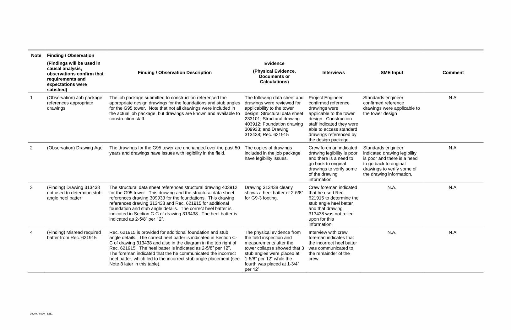
5.2 Observations and Findings
The key observations and findings are identified in the sequence of events in Appendix B and are
further described in Appendix C. For purposes of this discussion, observations are actions and
conditions that met expected requirements and results. Findings are actions or conditions that
did not meet requirements and these findings are used in the causal analysis. A summary of the
observations and findings are described below.
Note 1: (Observation) Job package references appropriate drawing
The job package submitted to construction referenced the appropriate design drawings for the
foundations and stub angles for the G95 tower.25
Note that not all drawings were included in the
actual job package, but drawings were referenced, known by, and available to the construction
staff.26
The structural data sheet and drawings applicable to the tower design were structural data
sheet 233101; structural drawing 403912; foundation drawing 309933; drawing 313438; and
record 621915. These are the appropriate drawings for the construction of the G95 tower.27
Note 2: (Observation) Drawing Age
The drawings for the G95 tower are unchanged over the past 50 years, but the drawings contain
correct and appropriate information for erection of the G95 tower. There are issues with
legibility of the drawings in the field, but the construction crew has access to personnel at Davis
Service Center to assist in reading drawings, if legibility of the copies is an issue.28
Note 3: (Finding) Drawing 313438 not used to determine stub angle heel batter
The structural data sheet references structural drawing 403912 for the G95 tower. This drawing
and the structural data sheet references drawing 309933 for the foundations. This drawing
references drawing 313438 and Rec. 621915 for additional foundation and stub angle details.
The correct heel batter is indicated in Section C-C of drawing 313438. The heel batter is
indicated as 2-5/8” per 12”. The crew foreman indicated that he did not use this drawing for
determination of the heel batter, but used the referenced Rec. 621915 for the heel batter
determination. Figure 5 below shows the heel batter designation from drawing 313438.
25 Reference 2: Job package
26 Interviews with crew foreman
27 Interviews with engineering personnel
28 Interviews with crew and engineering; Reference 6: PG&E tower drawings
1600474.000 - 4172
15
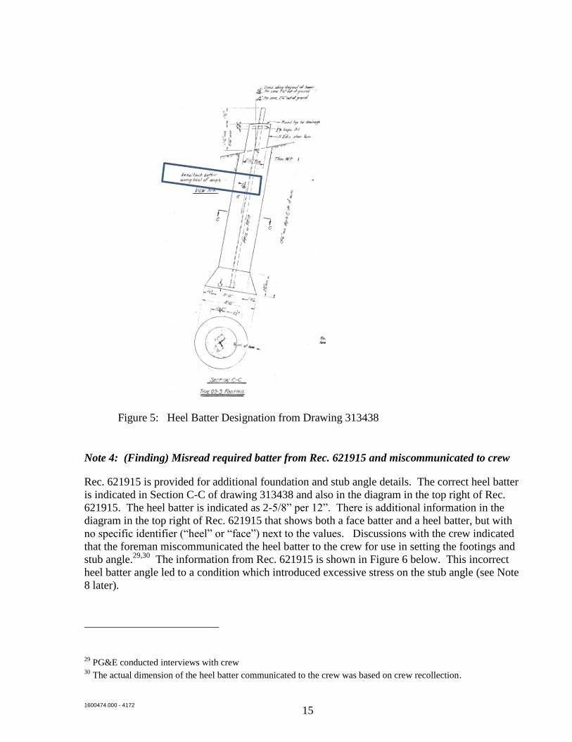
Figure 5: Heel Batter Designation from Drawing 313438
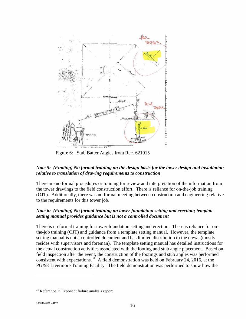
Note 4: (Finding) Misread required batter from Rec. 621915 and miscommunicated to crew
Rec. 621915 is provided for additional foundation and stub angle details. The correct heel batter
is indicated in Section C-C of drawing 313438 and also in the diagram in the top right of Rec.
621915. The heel batter is indicated as 2-5/8” per 12”. There is additional information in the
diagram in the top right of Rec. 621915 that shows both a face batter and a heel batter, but with
no specific identifier (“heel” or “face”) next to the values. Discussions with the crew indicated
that the foreman miscommunicated the heel batter to the crew for use in setting the footings and
stub angle.29,30
The information from Rec. 621915 is shown in Figure 6 below. This incorrect
heel batter angle led to a condition which introduced excessive stress on the stub angle (see Note
8 later).
29 PG&E conducted interviews with crew
30 The actual dimension of the heel batter communicated to the crew was based on crew recollection.
1600474.000 - 4172
16
Figure 6: Stub Batter Angles from Rec. 621915
Note 5: (Finding) No formal training on the design basis for the tower design and installation
relative to translation of drawing requirements to construction
There are no formal procedures or training for review and interpretation of the information from
the tower drawings to the field construction effort. There is reliance for on-the-job training
(OJT). Additionally, there was no formal meeting between construction and engineering relative
to the requirements for this tower job.
Note 6: (Finding) No formal training on tower foundation setting and erection; template
setting manual provides guidance but is not a controlled document
There is no formal training for tower foundation setting and erection. There is reliance for on-
the-job training (OJT) and guidance from a template setting manual. However, the template
setting manual is not a controlled document and has limited distribution to the crews (mostly
resides with supervisors and foreman). The template setting manual has detailed instructions for
the actual construction activities associated with the footing and stub angle placement. Based on
field inspection after the event, the construction of the footings and stub angles was performed
consistent with expectations.31
A field demonstration was held on February 24, 2016, at the
PG&E Livermore Training Facility. The field demonstration was performed to show how the
31 Reference 1: Exponent failure analysis report
1600474.000 - 4172
17
footings were located and bored and how the stub angles were set. This demonstration was
performed consistent with the template setting manual.
Note 7: (Finding) Stub angle placed at incorrect angle
Three stub angles (A, B, D) were inclined at a batter of 1-5/8” per 12” and the fourth (C) at 1-
3/4” per 12” vs. the required 2-5/8” per 12” per the field inspection after the event.32
Note 8: (Finding) Inspection and verification requirements not adequate (pre-concrete pour
and post-concrete pour)
There are no requirements established for independent verification activities for determination of
dimensions from the tower drawings.33
There was no verification of the stub angle batter for this
tower erection against the information in the drawing at this location.34
Note 9: (Finding) No guidance on fit-up tolerances
Tolerances are not provided on the tower foundation and stub angle drawings related to the stub
angle batter and dimensions between stub angles. Interviews with engineering confirmed that
the stub angles are required to match the drawing dimension to validate the design assumptions
for the tower. Additionally, there is no guidance provided for dimensional tolerances (e.g.
dimensions F and S “to theoretical heel of top of stub”, see drawing 313438).35
Note 10: (Finding) No identification of misalignment of stub angles (during fit-up at top of
17-1/2 ft. legs, during installation of bracing, and during bolt tightening)
There was no identification of the stub angle misalignment with the lower tower legs during the
tower installation.36
The construction sequence for a tower erection includes significant amount
of movement of various members, until the tower bolts are tightened. Therefore, there is limited
opportunity for visual clues that there may be a tower erection problem relative to fit-up. The
crew indicated that they did not observe anything during this installation that was out-of-the
ordinary for tower erection. Additionally, there is no formal training to alert construction crew
members on what to look for during construction that may be indicative of a problem.
Note 11: (Finding) Tower collapse
The tower collapsed on October 18, 2015, and caused damage to an adjacent tower. This is the
failure event.
32 Reference 1: Exponent failure analysis report
33 Review of template setting manual and lack of formal procedures
34 Interviews with crew foreman and crew lead
35 Interview with construction crew and engineering personnel
36 Interviews with crew foreman and crew lead
1600474.000 - 4172
18
The findings identified above are used as starting points in the causal analysis that follows.
Observations were provided to describe a complete picture of the activities and conditions during
the tower installation.
1600474.000 - 4172
19
6. Causal Analysis
6.1 Causal Analysis
The Event and Causal Factor Analysis (ECFA) is used to evaluate the cause for each of the
findings previously determined. The analysis is performed by looking at the causal chain for
each finding, based on the evidence and facts gathered during the data collection activities. The
ECFA is presented in the causal diagram shown in Appendix D. This section describes the
results of the ECFA.
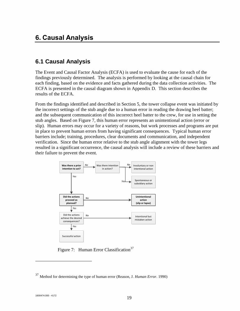
From the findings identified and described in Section 5, the tower collapse event was initiated by
the incorrect settings of the stub angle due to a human error in reading the drawing heel batter;
and the subsequent communication of this incorrect heel batter to the crew, for use in setting the
stub angles. Based on Figure 7, this human error represents an unintentional action (error or
slip). Human errors may occur for a variety of reasons, but work processes and programs are put
in place to prevent human errors from having significant consequences. Typical human error
barriers include; training, procedures, clear documents and communication, and independent
verification. Since the human error relative to the stub angle alignment with the tower legs
resulted in a significant occurrence, the causal analysis will include a review of these barriers and
their failure to prevent the event.
Figure 7: Human Error Classification37
37 Method for determining the type of human error (Reason, J. Human Error. 1990)
Was there a prior intention to act?
Was there intention in action?
Involuntary or non intentional action
Spontaneous or subsidiary action
Did the actions proceed as planned?
Did the actions achieve the desired
consequences?
Successful action
Unintentional action
(slip or lapse)
Intentional but mistaken action
No No
Yes
No
Yes
No
Yes
Yes
1600474.000 - 4172
20
Based on the causal analysis of the problem statement and the findings previously identified, the
causal analysis is provided in the chart in Appendix D, and described below.
The causal analysis chain starts with the tower collapse, which was caused by the stub angles
being installed at the incorrect angle (batter).
There are two causes of the stub angles at the incorrect angle:
1. The angle was misread from the design drawings, and this incorrect angle was
communicated to the crew for their foundation setting work. Interviews with the PG&E
crew foreman indicated that he misread the drawing angle and communicated this
incorrect information to the crew.38
Exponent concludes this was a human error. Human
errors are typically prevented by processes related to training, procedures and
verification.
The first causal chain for this error relates to an insufficient review of the job package.
Prior to construction, the crew foreman received all pertinent engineering drawings for
setting the foundation of the tower in question.
o During the review of the job package, the foreman indicated that he misread the
heel batter inclination on Rec 621915. Additionally, drawing 313438 was not
used to determine the heel batter. These actions for ineffective review were
caused by inadequate training, relative to transferring design information into the
construction plan for the footing set-up. The inadequate training is caused
because there is no formal training program for the construction crews on
interpreting the design-related information to construction. Currently, on-the-job
training is relied upon for transferring knowledge to the crew. This approach may
have been effective in the past, but there are fewer towers being constructed
today, and the on-the-job training approach may no longer be sufficient. The lack
of a formal training program is caused by inadequate program design to identify
the need for formal training of the crew, relative to understanding and interpreting
the design drawings for construction.
o A lack of clarity and confusing information in the construction drawing (Rec.
621915) also resulted in the misreading of the tower design drawing39
. This is
caused by the use of legacy drawings (dating from the 1960’s). The legacy tower
drawings may not reflect the current needs of crews who perform the tower
installations on an infrequent basis. The lack of drawing clarity results from
38 Interview with crew foreman and crew lead
39 Exponent reviewed drawings for various tower designs and there was a great variance in drawing clarity and
how information was conveyed on the drawings related to heel and face batter. These variances indicate the
potential for more formal training relative to construction review and understanding of the design drawings.
1600474.000 - 4172
21
inadequate maintenance and updated drawings to factor in the current needs of the
construction crews.
o The limited interface between engineering and construction contributed to the
incorrect stub angle batter not being successfully transferred to the crew
performing the construction. Given the criticality of this parameter and the
presence of potential barriers, such as clarity and familiarity, which affect the
ability of the message being successfully received, feedback is a reasonable way
to assure the desired communication has taken place. Structured dialogue
between engineering and construction provides an opportunity to reinforce
training in reading and interpreting drawings, as well as for independent
verification of the drawing information to the construction effort. The absence of
robust training verification and documentation is caused by inadequate program
design to identify the need for independent verification of the dimensions taken
from the design drawings.
The second causal chain for the insufficient review of the job package relates to no
requirement for an independent verification of the footing and stub angle settings relative
to the design requirements. This is caused by the lack of procedures for an independent
verification of the critical dimensions. This check is also not included in the template
setting manual. The lack of the procedures is caused by inadequate program design to
identify the need for independent verification of the dimensions taken from the design
drawings.
2. There was no identification by the crew of potential misalignment issues with the tower.
There was no evidence in documents or interviews with the crew that indicated that
anything out-of-the-normal occurred during the construction and installation process.
This was caused by the lack of guidance provided to the construction crew on tolerances
for the tower design and issues to be observed during the construction process. This is
caused by a further lack of guidance on when engineering needs to be contacted
regarding field issues. This lack of guidance is caused by the lack of formal training for
the construction crews on the overall design basis of the towers, as previously described.
6.2 Root and Contributing Causes
This section provides the results of the causal analysis to identify the root causes of the incident.
Appendix E provides the evaluation of the causes identified in Section 6.1 to determine the root
cause of the incident. The determination of the root causes is based on evaluating the causes at
the ends of the causal chains, and determining whether these would have prevented or
significantly reduced the probability of the incident, and whether they are under the control of
management.
Based on the problem statement and the evaluation in Appendix E, the root cause of the incident
is:

1600474.000 - 4172
22
RC1: Inadequate process to ensure that critical parameters (dimensions and/or steps)
of the transmission towers are constructed as designed: The predefined verification
methodology to ensure that design information from the tower drawings is correctly
transferred to the construction installation process should be improved. There is no
formal requirement to verify the take-offs from the drawings. Since the stub angle
inclination is a key dimension for validating the tower design, a defined means to
determine and confirm this dimension is required.
The determination of the contributing causes is based on evaluating the causes at the ends of the
causal chains, determining whether these would have helped to reduce the probability of the
incident, and whether they are under the control of management. Based on the problem
statement and the evaluation in Appendix E, the contributing causes of the incident are:
CC1: Inadequate process design relative to training requirements for tower drawings
for transfer of design-related information to the construction crews: The tower
construction utilizes general drawings and not site specific drawings. There is no formal
training that provides the construction crew with information on what drawings to review
and how to interpret these drawings. Also, the key parameters that govern the design are
not communicated, except through informal on-the-job training. Additionally, there is a
need for the crew foreman to perform a significant number of calculations on-site to
transfer the design information to the field. Formal training provides a basis for
understanding requirements, and gaining necessary information on significant design
considerations, as impacted by construction activities. Also, tower erection is not
performed frequently and the use of OJT exclusively may no longer be sufficient.
CC2: Inadequate maintenance (update) of drawings relative to legacy tower drawings
may not reflect the current needs of crews who perform the tower installations on an
infrequent basis: The tower drawings are very dated and last updated in the 1960’s.
Therefore, this causes potential error in reading the drawings due to legibility issues, as
well as missing or confusing information.
CC3: Inadequate process design relative to training requirements for tower drawings
on dimensional tolerances and potential field issues: This cause is similar to CC1
except that it relates to the field identification of potential issues. There is no formal
guidance provided to the crews relative to fit-up tolerances on critical dimensional
measurements and other field observations that may indicate a problem.
1600474.000 - 4172
23
7. Recommended Corrective Actions
The desired outcome of a root cause analysis is to identify corrective actions to prevent
recurrence of the problem. Effective corrective actions are those that address the root cause, are
implementable by the organization, are cost effective, and are consistent with company business
goals and strategies.
The recommended corrective actions from the causal analysis are defined for application by
PG&E in processes that they control. Based on the root and contributing causes, the following
actions are recommended to prevent recurrence of the problem are listed in Table 1:
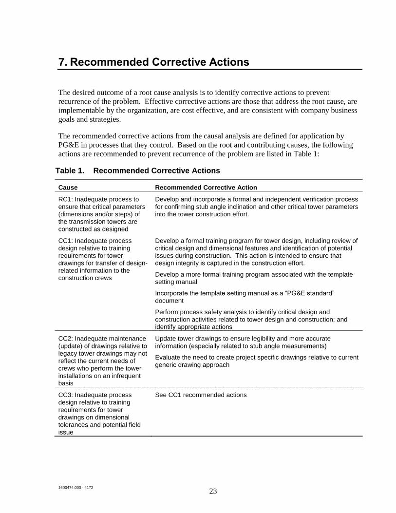
Table 1. Recommended Corrective Actions
Cause Recommended Corrective Action
RC1: Inadequate process to ensure that critical parameters (dimensions and/or steps) of the transmission towers are constructed as designed
Develop and incorporate a formal and independent verification process for confirming stub angle inclination and other critical tower parameters into the tower construction effort.
CC1: Inadequate process design relative to training requirements for tower drawings for transfer of design-related information to the construction crews
Develop a formal training program for tower design, including review of critical design and dimensional features and identification of potential issues during construction. This action is intended to ensure that design integrity is captured in the construction effort.
Develop a more formal training program associated with the template setting manual
Incorporate the template setting manual as a “PG&E standard” document
Perform process safety analysis to identify critical design and construction activities related to tower design and construction; and identify appropriate actions
CC2: Inadequate maintenance (update) of drawings relative to legacy tower drawings may not reflect the current needs of crews who perform the tower installations on an infrequent basis
Update tower drawings to ensure legibility and more accurate information (especially related to stub angle measurements)
Evaluate the need to create project specific drawings relative to current generic drawing approach
CC3: Inadequate process design relative to training requirements for tower drawings on dimensional tolerances and potential field issue
See CC1 recommended actions
1600474.000 - 4172
24
8. Extent of Condition
The causal investigation focused on the specific incident only; and the evaluation of extent of
condition issues were undertaken as a separate effort by PG&E. For this incident, the extent of
condition issues relate to the stub angle placement for the larger towers. PG&E has undertaken a
review of the 36 towers constructed over the past two years that utilized tower designs
incorporating stub angle foundations. Based on this review40
, all of these tower stub angles were
installed correctly with no signs of stress. Therefore, there are no further actions required for the
evaluation of extent of condition.
40 Reference 11: PG&E tower review file
1600474.000 - 4172
25
9. Conclusions
The objectives of this root cause analysis were to determine the root and contributing causes and
define the actions to prevent recurrence. From the findings identified, the tower collapse event
was initiated by the incorrect settings of the stub angle due to a human error in determining the
drawing heel batter; and the subsequent communication of this incorrect heel batter to the crew
for use in setting the stub angles. Typical human error defenses (barriers to prevent human error)
include training, procedures, clear documents and communication, and independent verification.
Since the human error relative to the stub angle alignment with the tower legs resulted in a
significant occurrence, the causal analysis includes a review of these barriers and their
performance and contribution to the incident.
Based on the causal evaluation, the root and contributing causes of the incident are listed below:
Root Cause: Inadequate process to ensure that critical parameters (dimensions and/or
steps) of the transmission towers are constructed as designed: The verification
methodology to ensure that design information from the tower drawings is correctly
transferred to the construction installation process should be improved. There is no
formal requirement to verify the take-offs from the drawings.
Contributing Cause 1: Inadequate process design relative to training requirements for
tower drawings for transfer of design-related information to the construction crews: The
tower construction utilizes general drawings and not site specific drawings. There is no
formal training that provides the construction crew with information on what drawings to
review and how to interpret these drawings. Also, the key parameters that govern the
design are not communicated except through informal on-the-job (OJT) training.
Contributing Cause 2: Inadequate maintenance (update) of drawings relative to legacy
tower drawings may not reflect the current needs of crews who perform the tower
installations on an infrequent basis: The tower drawings are very dated and last updated
in the 1960’s. Therefore, this causes the potential for error in reading the drawings due to
legibility issues, as well as missing or confusing information.
Contributing Cause 3: Inadequate process design relative to training requirements for
tower drawings on dimensional tolerances and potential field issues: This cause is
similar to Contributing Cause 1, except that it relates to the field identification of
potential issues. There is no formal guidance provided to the crews relative to fit-up
tolerances on critical dimensional measurements, and other field observations that may
indicate a problem.
Recommended corrective actions are identified and included in Section 7. The extent of
condition was performed by PG&E and indicated no other towers were constructed within
correct stub angle batter over the past two years as described in Section 8.
1600474.000 - 4172
26
10. References
1. “Moss Landing Tower Collapse Analysis”; Exponent, Inc., dated December 18, 2015.
2. “Job Package: Moss Landing 230/115 kV BAAH Project Phase 2 Construction Binder”;
Black & Veatch
3. “As-Built Mark-Ups”; prepared by (PG&E)
4. Template Setters Training Manual
5. Structural Data Sheet 233101
6. Structural Drawing 403912
7. Foundation drawing 309933
8. Drawing 313438
9. Drawing: Rec. 621915
10. Interview Notes Summary from
11. Review file: Moss_Landing_CA_Tower_Inspections.xlsx
12. US Department of Energy, Human Performance Handbook, Human Performance
Improvement Concepts and Principles, 2007
13. Bea, R.G. Human & Organizational Factors: Quality & Reliability of Engineered Systems,
Volume 1. 2008

Appendix A
Interview List
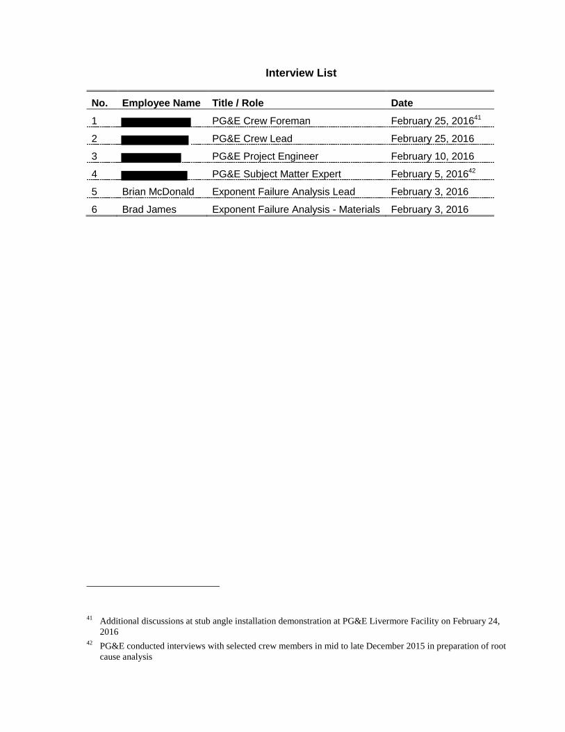
Interview List
No. Employee Name Title / Role Date
1 PG&E Crew Foreman February 25, 201641
2 PG&E Crew Lead February 25, 2016
3 PG&E Project Engineer February 10, 2016
4 PG&E Subject Matter Expert February 5, 201642
5 Brian McDonald Exponent Failure Analysis Lead February 3, 2016
6 Brad James Exponent Failure Analysis - Materials February 3, 2016
41 Additional discussions at stub angle installation demonstration at PG&E Livermore Facility on February 24,
2016 42
PG&E conducted interviews with selected crew members in mid to late December 2015 in preparation of root
cause analysis
Appendix B
Event Timeline and Process Comparison
Job Package
Tower Construction
Planning (Job Package
Received)
Tower Foundation
Layout
Placement of Stub Angles
1. Job package references appropriate drawings
5. No formal training on the design basis for the tower design and installation relative to translation of drawing requirements to construction
7. Stub angle placed at incorrect angle
Review Structural Data
Sheet(Dwg. 233101)
from Job Package
Obtain & Review Add’l
Drawings(Dwg. 403912
struct. & 309933 found.)
from Davis
Obtain & Review Dwgs
for Foundation & Stub Angle
(Dwg. 313438; Rec. 621915)
Determine stub angle
batter
4. Misread required batter from Rec. 621915 and miscommunicated to crew
Selection of remaining template
information
Engineering / Design
Construction Supv/ Foreman
Foreman Land DeptForeman /
CrewForeman /
Crew
Review Tower Portion of Job
Package
Notes1. Numbered comments in “red” represent findings that will be used in the causal analysis.2. Numbered comments in “black” represent observations that are consistent with requirements and expectations.3. Un-numbered comments are for information only.
Location of Tower
Determined
2. Last drawing revision is 1962 (313438) and 1950's approx. (indeterminate for 621915)
2. Last drawing revision is 1958 (309933) and 1973 (403912)
3. Drawing 313438 not used to determine stub angle heel batter
Verification of Stub Angle Geometry
Pouring of Concrete Footings
Re-verification of Stub Angle
Geometry
8. Inspection and verification requirements not adequate
8. Inspection and verification requirements not adequate
Tower Erection
Completion of Tower Erection
Tower Collapse
10. No identification of misalignment of stub angles
11. Tower failure
Place bottom tower legs
Connect tower legs to
members at top of 17-1/2
ft section
Connect lower tower
members
Tighten bolts from top to bottom of 17-1/2 ft section
10. No identification of misalignment of stub angles
10. No identification of misalignment of stub angles
Tighten bolts between tower legs and stub
angles
10. No identification of misalignment of stub angles
Comment: Opportunity to observe significant offset or hoist loading
Comment: Opportunity to observe difficulty tightening bolts; unusual sounds
9. No guidance on fit-up tolerances
Stringing of conductors
Foreman / Crew
Foreman / Crew
Foreman / Crew
Foreman / Crew
Foreman / Crew
Lineman Crew
Prepare as-built drawings
Foreman / Crew
Comment: Opportunity to observe unusual member deflections
6. No formal training on tower foundation setting and erection; template setting manual provides guidance but is not a controlled document
Appendix C
Findings Description and Evidence
1600474.000 - 8281
Note Finding / Observation
(Findings will be used in causal analysis; observations confirm that requirements and expectations were satisfied)
Finding / Observation Description
Evidence
(Physical Evidence, Documents or Calculations)
Interviews SME Input Comment
1 (Observation) Job package references appropriate drawings
The job package submitted to construction referenced the appropriate design drawings for the foundations and stub angles for the G95 tower. Note that not all drawings were included in the actual job package, but drawings are known and available to construction staff.
The following data sheet and drawings were reviewed for applicability to the tower design: Structural data sheet 233101; Structural drawing 403912; Foundation drawing 309933; and Drawing 313438; Rec. 621915
Project Engineer confirmed reference drawings were applicable to the tower design. Construction staff indicated they were able to access standard drawings referenced by the design package.
Standards engineer confirmed reference drawings were applicable to the tower design
N.A.
2 (Observation) Drawing Age The drawings for the G95 tower are unchanged over the past 50 years and drawings have issues with legibility in the field.
The copies of drawings included in the job package have legibility issues.
Crew foreman indicated drawing legibility is poor and there is a need to go back to original drawings to verify some of the drawing information.
Standards engineer indicated drawing legibility is poor and there is a need to go back to original drawings to verify some of the drawing information.
N.A.
3 (Finding) Drawing 313438 not used to determine stub angle heel batter
The structural data sheet references structural drawing 403912 for the G95 tower. This drawing and the structural data sheet references drawing 309933 for the foundations. This drawing references drawing 313438 and Rec. 621915 for additional foundation and stub angle details. The correct heel batter is indicated in Section C-C of drawing 313438. The heel batter is indicated as 2-5/8” per 12”.
Drawing 313438 clearly shows a heel batter of 2-5/8” for G9-3 footing.
Crew foreman indicated that he used Rec. 621915 to determine the stub angle heel batter and that drawing 313438 was not relied upon for this information.
N.A. N.A.
4 (Finding) Misread required batter from Rec. 621915
Rec. 621915 is provided for additional foundation and stub angle details. The correct heel batter is indicated in Section C-C of drawing 313438 and also in the diagram in the top right of Rec. 621915. The heel batter is indicated as 2-5/8” per 12”. The foreman indicated that the he communicated the incorrect heel batter, which led to the incorrect stub angle placement (see Note 8 later in this table).
The physical evidence from the field inspection and measurements after the tower collapse showed that 3 stub angles were placed at 1-5/8” per 12” while the fourth was placed at 1-3/4” per 12”.
Interview with crew foreman indicates that the incorrect heel batter was communicated to the remainder of the crew.
N.A. N.A.
1600474.000 - 8281
Note Finding / Observation
(Findings will be used in causal analysis; observations confirm that requirements and expectations were satisfied)
Finding / Observation Description
Evidence
(Physical Evidence, Documents or Calculations)
Interviews SME Input Comment
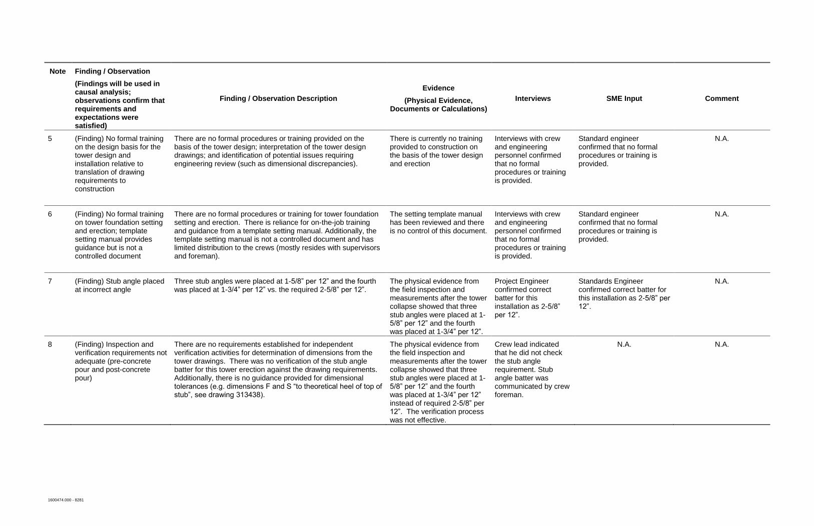
5 (Finding) No formal training on the design basis for the tower design and installation relative to translation of drawing requirements to construction
There are no formal procedures or training provided on the basis of the tower design; interpretation of the tower design drawings; and identification of potential issues requiring engineering review (such as dimensional discrepancies).
There is currently no training provided to construction on the basis of the tower design and erection
Interviews with crew and engineering personnel confirmed that no formal procedures or training is provided.
Standard engineer confirmed that no formal procedures or training is provided.
N.A.
6 (Finding) No formal training on tower foundation setting and erection; template setting manual provides guidance but is not a controlled document
There are no formal procedures or training for tower foundation setting and erection. There is reliance for on-the-job training and guidance from a template setting manual. Additionally, the template setting manual is not a controlled document and has limited distribution to the crews (mostly resides with supervisors and foreman).
The setting template manual has been reviewed and there is no control of this document.
Interviews with crew and engineering personnel confirmed that no formal procedures or training is provided.
Standard engineer confirmed that no formal procedures or training is provided.
N.A.
7 (Finding) Stub angle placed at incorrect angle
Three stub angles were placed at 1-5/8” per 12” and the fourth was placed at 1-3/4” per 12” vs. the required 2-5/8” per 12”.
The physical evidence from the field inspection and measurements after the tower collapse showed that three stub angles were placed at 1-5/8” per 12” and the fourth was placed at 1-3/4” per 12”.
Project Engineer confirmed correct batter for this installation as 2-5/8” per 12”.
Standards Engineer confirmed correct batter for this installation as 2-5/8” per 12”.
N.A.
8 (Finding) Inspection and verification requirements not adequate (pre-concrete pour and post-concrete pour)
There are no requirements established for independent verification activities for determination of dimensions from the tower drawings. There was no verification of the stub angle batter for this tower erection against the drawing requirements. Additionally, there is no guidance provided for dimensional tolerances (e.g. dimensions F and S “to theoretical heel of top of stub”, see drawing 313438).
The physical evidence from the field inspection and measurements after the tower collapse showed that three stub angles were placed at 1-5/8” per 12” and the fourth was placed at 1-3/4” per 12” instead of required 2-5/8” per 12”. The verification process was not effective.
Crew lead indicated that he did not check the stub angle requirement. Stub angle batter was communicated by crew foreman.
N.A. N.A.
1600474.000 - 8281
Note Finding / Observation
(Findings will be used in causal analysis; observations confirm that requirements and expectations were satisfied)
Finding / Observation Description
Evidence
(Physical Evidence, Documents or Calculations)
Interviews SME Input Comment
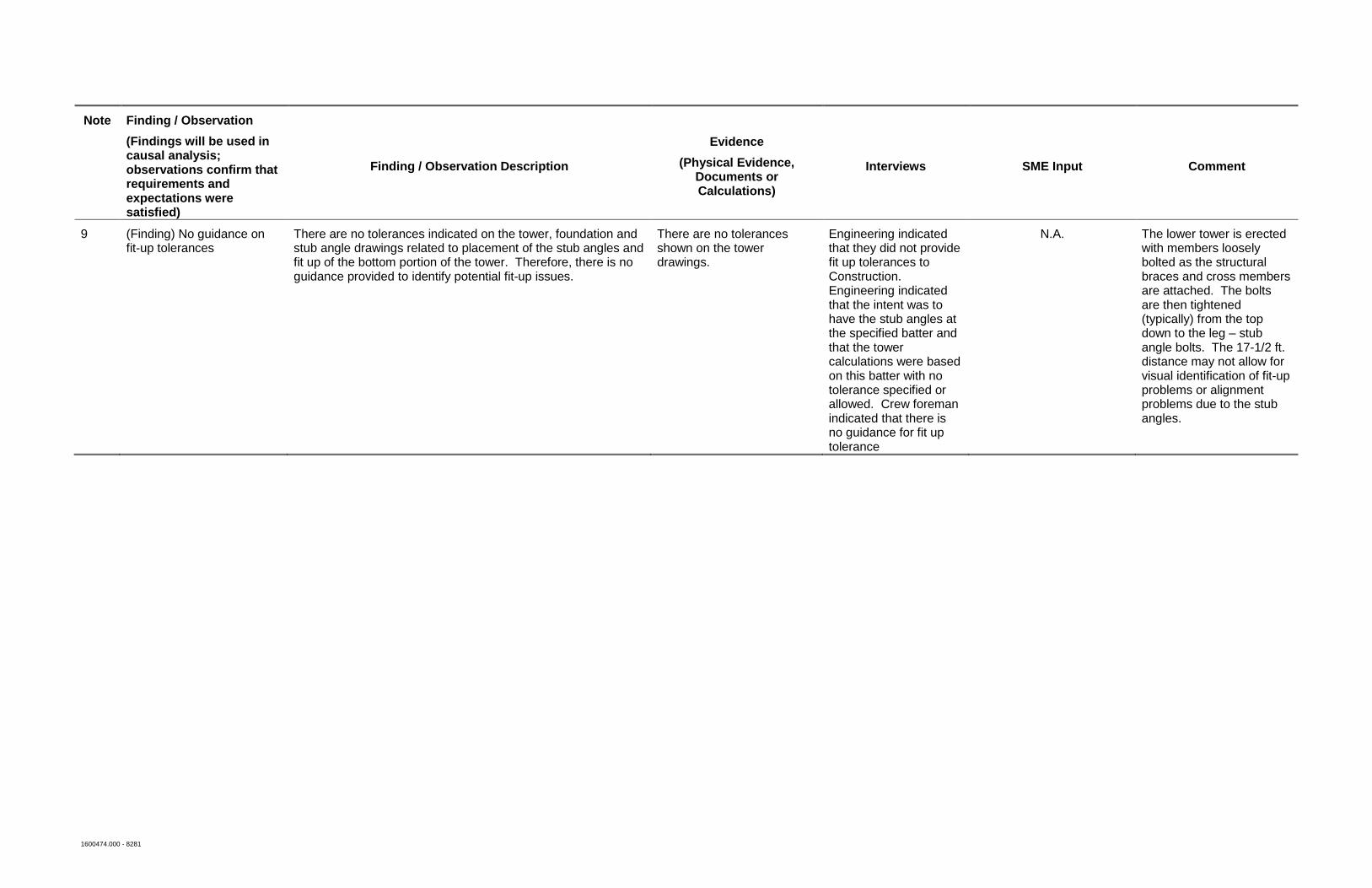
9 (Finding) No guidance on fit-up tolerances
There are no tolerances indicated on the tower, foundation and stub angle drawings related to placement of the stub angles and fit up of the bottom portion of the tower. Therefore, there is no guidance provided to identify potential fit-up issues.
There are no tolerances shown on the tower drawings.
Engineering indicated that they did not provide fit up tolerances to Construction. Engineering indicated that the intent was to have the stub angles at the specified batter and that the tower calculations were based on this batter with no tolerance specified or allowed. Crew foreman indicated that there is no guidance for fit up tolerance
N.A. The lower tower is erected with members loosely bolted as the structural braces and cross members are attached. The bolts are then tightened (typically) from the top down to the leg – stub angle bolts. The 17-1/2 ft. distance may not allow for visual identification of fit-up problems or alignment problems due to the stub angles.
1600474.000 - 8281
Note Finding / Observation
(Findings will be used in causal analysis; observations confirm that requirements and expectations were satisfied)
Finding / Observation Description
Evidence
(Physical Evidence, Documents or Calculations)
Interviews SME Input Comment
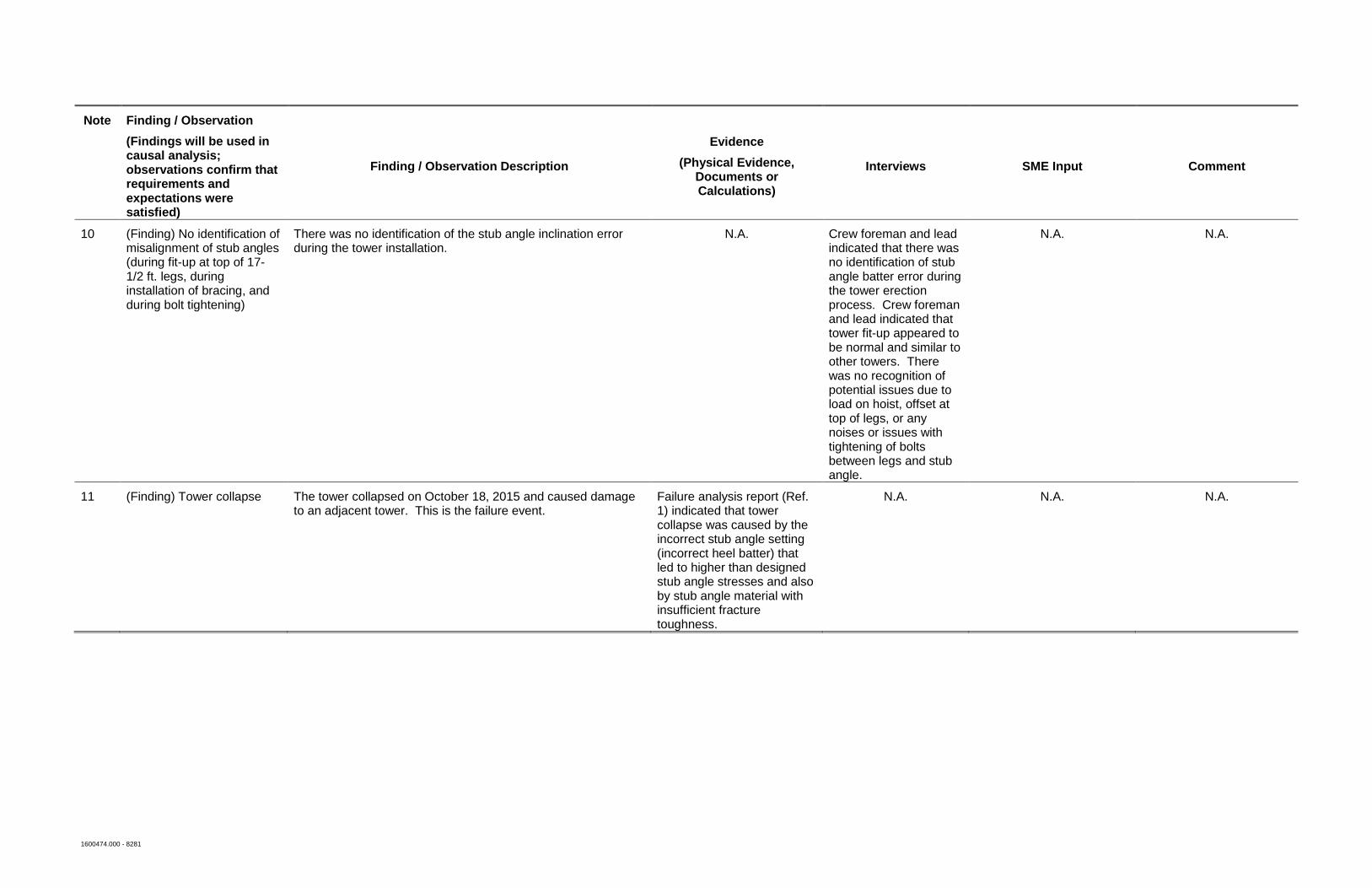
10 (Finding) No identification of misalignment of stub angles (during fit-up at top of 17-1/2 ft. legs, during installation of bracing, and during bolt tightening)
There was no identification of the stub angle inclination error during the tower installation.
N.A. Crew foreman and lead indicated that there was no identification of stub angle batter error during the tower erection process. Crew foreman and lead indicated that tower fit-up appeared to be normal and similar to other towers. There was no recognition of potential issues due to load on hoist, offset at top of legs, or any noises or issues with tightening of bolts between legs and stub angle.
N.A. N.A.
11 (Finding) Tower collapse The tower collapsed on October 18, 2015 and caused damage to an adjacent tower. This is the failure event.
Failure analysis report (Ref. 1) indicated that tower collapse was caused by the incorrect stub angle setting (incorrect heel batter) that led to higher than designed stub angle stresses and also by stub angle material with insufficient fracture toughness.
N.A. N.A. N.A.
Appendix D
Event and Causal Factors Chart
1600474.000 - 8281
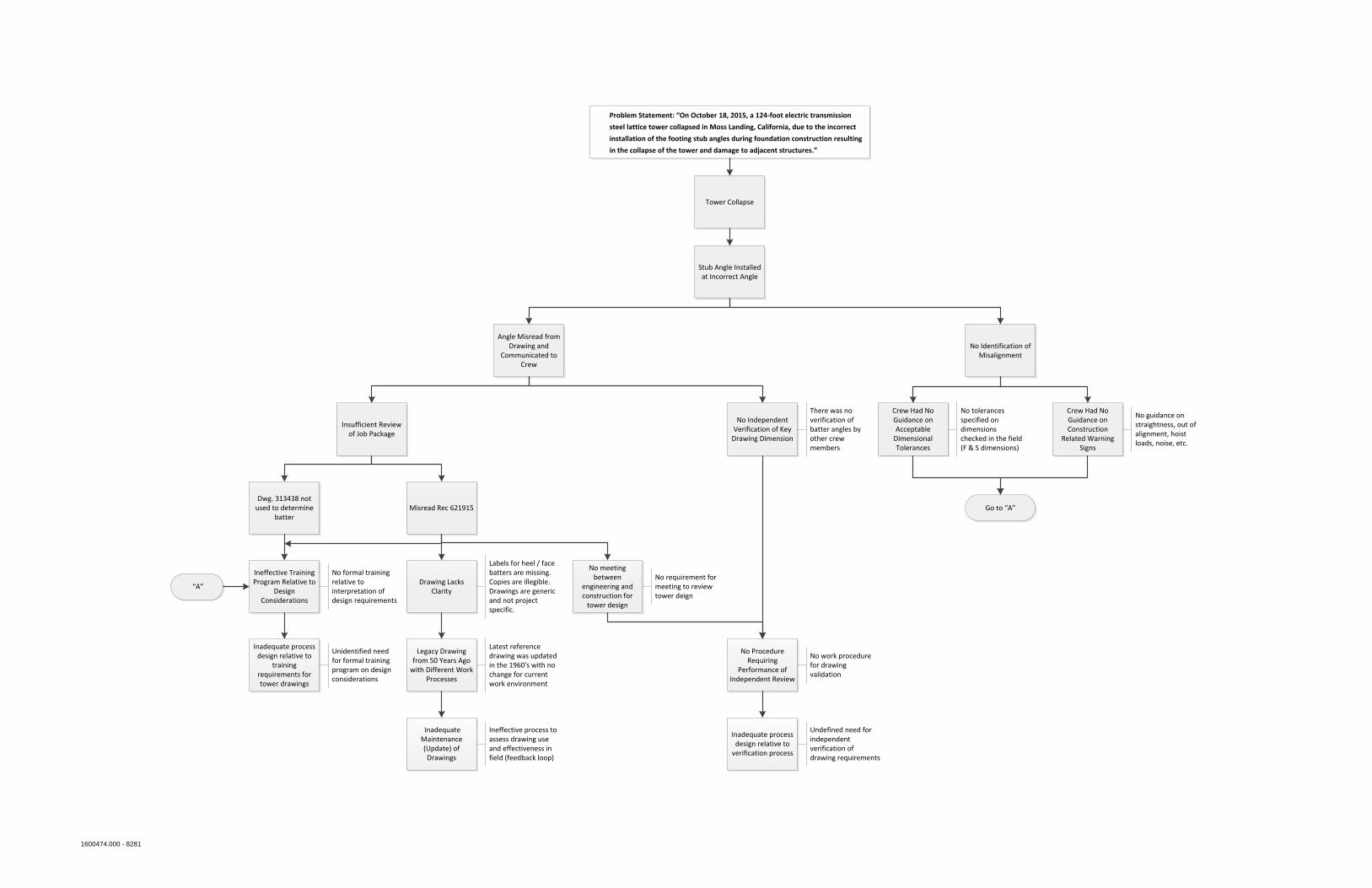
Tower Collapse
Stub Angle Installed at Incorrect Angle
Angle Misread from Drawing and
Communicated to Crew
Dwg. 313438 not used to determine
batterMisread Rec 621915
Ineffective Training Program Relative to
Design Considerations
Insufficient Review of Job Package
Drawing Lacks Clarity
Legacy Drawing from 50 Years Ago
with Different Work Processes
Inadequate Maintenance (Update) of Drawings
Labels for heel / face batters are missing. Copies are illegible. Drawings are generic and not project specific.
Latest reference drawing was updated in the 1960's with no change for current work environment
Ineffective process to assess drawing use and effectiveness in field (feedback loop)
No formal training relative to interpretation of design requirements
No Independent Verification of Key
Drawing Dimension
There was no verification of batter angles by other crew members
No Procedure Requiring
Performance of Independent Review
Inadequate process design relative to
training requirements for tower drawings
Inadequate process design relative to
verification process
Undefined need for independent verification of drawing requirements
No Identification of Misalignment
Crew Had No Guidance on Acceptable
Dimensional Tolerances
No tolerances specified on dimensions checked in the field (F & S dimensions)
Crew Had No Guidance on Construction
Related Warning Signs
No guidance on straightness, out of alignment, hoist loads, noise, etc.
No work procedure for drawing validation
Problem Statement: “On October 18, 2015, a 124-foot electric transmission
steel lattice tower collapsed in Moss Landing, California, due to the incorrect
installation of the footing stub angles during foundation construction resulting
in the collapse of the tower and damage to adjacent structures.”
No meeting between
engineering and construction for
tower design
No requirement for meeting to review tower deign
Go to “A”
“A”
Unidentified need for formal training program on design considerations
1600474.000 - 8281
Appendix E
Causal Factors Analysis Chart
1600474.000 - 8281
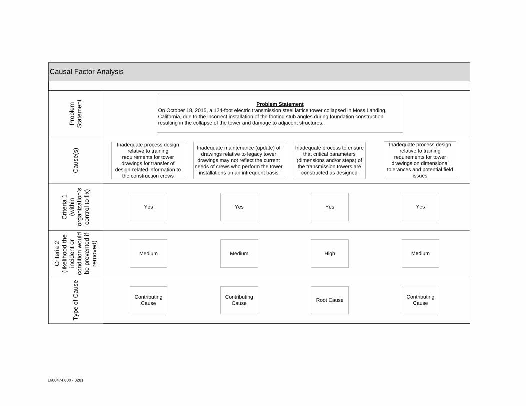
Causal Factor AnalysisT
ype o
f C
ause
Crite
ria 2
(lik
elih
ood the
incid
ent or
cond
itio
n w
ould
be p
revente
d if
rem
oved)
Crite
ria 1
(within
org
aniz
atio
n’s
contr
ol to
fix
)
Cau
se(s
)P
roble
m
Sta
tem
ent
Problem Statement
On October 18, 2015, a 124-foot electric transmission steel lattice tower collapsed in Moss Landing,
California, due to the incorrect installation of the footing stub angles during foundation construction
resulting in the collapse of the tower and damage to adjacent structures..
Inadequate process design
relative to training
requirements for tower
drawings for transfer of
design-related information to
the construction crews
Inadequate maintenance (update) of
drawings relative to legacy tower
drawings may not reflect the current
needs of crews who perform the tower
installations on an infrequent basis
Inadequate process to ensure
that critical parameters
(dimensions and/or steps) of
the transmission towers are
constructed as designed
Yes YesYes
Medium Medium High
Contributing
CauseRoot Cause
Contributing
Cause
Inadequate process design
relative to training
requirements for tower
drawings on dimensional
tolerances and potential field
issues
Yes
Medium
Contributing
Cause