Embed Size (px)
Citation preview
Monthly Progress Report Stanford Synchrotron Radiation Laboratory
July 2003
2
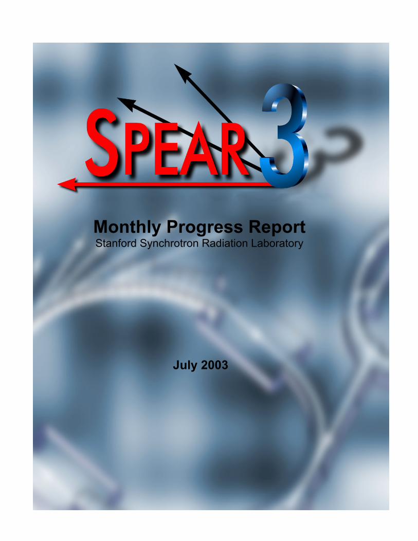
TABLE OF CONTENTS
Page A. Project Summary 1. Technical Progress 3 2. Cost Data 4 B. Design and Fabrication Reports
1.1 Magnets & Supports 5 1.2 Vacuum System 5 1.3 Power Supplies 5 1.4 RF System 6
1.5 Instrumentation & Controls 6 1.8 Facilities 7 C. Installation Reports 1.9.1 Mechanical Systems 9 1.9.3 Power Supply System 11 1.9.4 RF System 11 1.9.6 Cable Plant Installation 12 1.9.8 Facilities 13 2.0.2 Survey and Alignment 14 .
3
A. SPEAR 3 PROJECT SUMMARY 1. Technical Progress July completes the 4th month of the SPEAR3 installation program. The planned activities continue on schedule. A major achievement this month was the preparation of the floor mounting plates for the magnet rafts, beam line front ends, and all straight section components. Starting June 30th, some two thousand holes were drilled in the new tunnel floor for the support studs. This was followed by final alignment and grouting of the floor support plates for all of the components. The work was accomplished by August 4, 2003 ahead of schedule (see photo’s in Section 1.9.1). This month also completes the design and fabrication efforts for the magnet and support area and the RF system. In summary, the following systems are complete, i.e. all components are ready for installation and the accounts have been closed:
1.1 Magnet and Supports 1.3 Power Supplies 1.4 RF Systems 1.6 Cable Plant
1.7 Beam Line Front Ends Work continues for remaining components in the (1.2) Vacuum System and mainly for the High Conductivity Water (HCW) system completion in (1.8) Facilities. WBS 1.5, Instrumentation and Controls, because of its complexity, does not have a separate installation account and thus will continue to include both design-fabrication and installation efforts. Note that all 4 RF cavities have now been tested and are ready for installation, which is scheduled for September. SLAC is now in the process of testing two new and two repaired 1.2 MW Klystrons. One of these will be available for SPEAR3 installation before October 1. The only remaining major contract (Phase II) for cable installation is now underway. It involves final power and signal cable connections within the tunnel and the power supply building that could not be done prior to the current shutdown period. Note that most of the cable placement around the outside of the tunnel and to areas within the power supply building were accomplished in Phase I prior to the current shutdown period. At this time the project is still headed toward its planned completion near the end of October. The Accelerator Readiness Review for SPEAR3 is scheduled for September 9, 10 and 11 and the DOE Review that will focus on CD4 is scheduled for October 10.
4
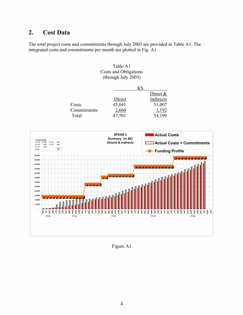
2. Cost Data The total project costs and commitments through July 2003 are provided in Table A1. The integrated costs and commitments per month are plotted in Fig. A1
Table A1 Costs and Obligations (through July 2003)
K$ Direct & Direct Indirects Costs 45,041 51,007 Commitments 2,660 3,192 Total 47,701 54,199
SPEAR 3Summary (in $K)
Directs & Indirects
-
5,000
10,000
15,000
20,000
25,000
30,000
35,000
40,000
45,000
50,000
55,000
60,000
JUN
JUL
AU
G
SEP
OC
T
NO
V
DEC
JAN
FEB
MA
R
APR
MA
Y
JUN
JUL
AU
G
SEP
OC
T
NO
V
DEC
JAN
FEB
MA
R
APR
MA
Y
JUN
JUL
AU
G
SEP
OC
T
NO
V
DEC
JAN
FEB
MA
R
APR
MA
Y
JUN
JUL
AU
G
SEP
OC
T
NO
V
DEC
JAN
FEB
MA
R
APR
MA
Y
JUN
JUL
AU
G
SEP
FY 99 FY 00 FY 01 FY 02 FY 03
Funding ProfileFY 99 $14M FY 02 10MFY 00 14M FY 03 10MFY 01 10M .Total 58M
Actual Costs
Actual Costs + Commitments
Funding Profile
Figure A1

5
B. Design and Fabrication Reports 1.1 Magnets and Supports
• With final electrical checks, all work has been completed for the 54-magnet rafts (includes all lattice magnets and their vacuum chambers) and they are ready to install.
• The injection Beam Transport System (BTS) has been completed.
• Septum magnet end-plates were modified to clear the vacuum chamber, final magnetic
measurements were made, and the magnet was installed on its support frame. 1.2 Vacuum System While the vacuum chambers through the main magnet system have been completed as reported above, work continues on an assortment of connecting straight section chambers, and associated instrumentation as summarized below. Work completed this month includes:
• The K1, K2, and K3 kicker magnet chambers • The injection septum magnet chamber • The RF HOM drift chambers. • Tune driver bellows. • All straight section support rafts. • Injection Transition/pump chambers and spool pieces
Work is continuing on the following:
• PPS stopper (95% complete) • DCCT (90% complete)
• Girder chamber pump installation
• Six remaining straight sections
• Girder and straight section bellows brazing
• Beam line 5, 9, and 10 transition chambers
• RF drift sections (80% complete) and RF entrance/exit transition chambers

6
1.3 Power Supplies All magnet power supplies have been received except for five 500A Intermediate Units. Delivery of these from IE Power is scheduled for the first week in August. This delivery date will support installation. It was observed that the central processing units (CPUs) in the multi-channel bipolar power supply controllers did not boot up when 5V power was applied. This problem was corrected by Synergy, the CPU manufacturer. Investigation revealed that the CPU needs several on-board voltage sources (converted from the SSRL external +5V supply) to be simultaneously applied to the CPU core. Two modified CPUs were received from Synergy. They were extensively tested without problems. Synergy will repair all the CPUs. Temporary AC power was connected to the pulsers that were recently installed in B118. The pulsers were used to test the production K1 and K2 kicker magnets. The pulsers turned on without incident and the magnet tests also proved successful. 1.4 RF System
• Cavities: The 500 kW klystron used for RF conditioning of the SPEAR3 cavities (as reported in the June Monthly report) had failed during processing of the SP3-03 cavity. A repair of the gun ceramic was made and the final SP3-04 cavity was successfully processed to 850 kV. This means that all 4 SPEAR3 cavities have now been successfully processed to full RF voltage and are ready for installation.
• Klystron: High power testing of the SLAC build 1.2 MW klystron, S/N 03 has been completed and it will be installed on PEP-II during the summer downtime.
The second SLAC built klystron S/N 04 has started high power testing and, now that RF cavity testing is completed, will continue on August 18. This klystron will then be installed in HER station 8-5 on PEP-II.
SLAC built tubes S/N 05 and 06 are expected to go on bake by September 15 and December 1 respectively. This means that each should be ready for installation by November 1 and January 19, 2004.
The CPI repaired Marconi klystron S/N 03 is now at SLAC and will be high power tested immediately following SLAC tube S/N 04. This klystron will be employed on SPEAR3 initially and upgraded at a later date to a SLAC built tube. The second CPI repaired Marconi klystron S/N 04 is expected at SLAC by August 29.
• Low Level RF (LLRF): All LLRF modules are expected to be installed and tested by the end of August.
7
1.5 Instrumentation and Control Systems
• Work on the computer control system is ongoing and significant progress was made in the detailed programming and configuration of MCOR power supply controllers, the BPM data acquisition system, the SPEAR control database, and the device control panels. MCOR control testing is in progress and plans for a full crate test are in the works. Design and fabrication of the prototype Time-Stamp/Sync Module is near completion and testing will begin in August. Computer network components have been ordered and some have been received.
• The first phase testing of the 60 4-button-multiplexed BPM processing modules from
Bergoz is complete and all modules have been accepted. The second phase of testing, where calibration of “SDEMOD” processing is determined, is now beginning. Fabrication of BPM system interconnection components continues. Installation of BPM patch panels will begin soon, and all BPM jumper cables have been received from the outside vendor. Installation of AC power for East and West I&C rooms will begin in August.
• The fabrication of the LO, Clock and Test Tone fan-out units and the Tune/Bunch
Monitor units is in progress. The design of the BPM-based current monitor is complete and fabrication has begun.
• The design of the Injection Timing Controller, which communicates with the Booster RF
Signal Generator, in nearly complete, with delivery now expected in September. Other timing control units and the Booster RF generator are complete.
• Detailed configuration of the programmable logic controller systems for the vacuum and
magnet water protection interlocks is in progress. Production of the Orbit Interlock Position Limit Detector chassis and the Summary Chassis is in progress.
• Fabrication of the Average Current Monitors for the Beam Containment System is
complete. Fabrication of the Long Ion Chamber (LION) control chassis and the Beam Current Interlock will continue over the next two months.
• Installation of I&C equipment into their racks is now in progress.
8
1.8 Facilities
LCW System • The installation is complete for the East and West straight sections and pressure tests are
underway.
• North and South arc pipe modifications are underway to meet SPEAR3 specs.
• Header and flex hose connections are underway.
• LCW for the building 514 RF power supply is complete.
• Building 118 LCW for power supplies will be complete in September.
HCW System • The new piping system design from the HCW skid to the RF klystron station has been
approved by the Earthquake Safety Committee. Parts have been ordered and installation is scheduled to being in August.
9
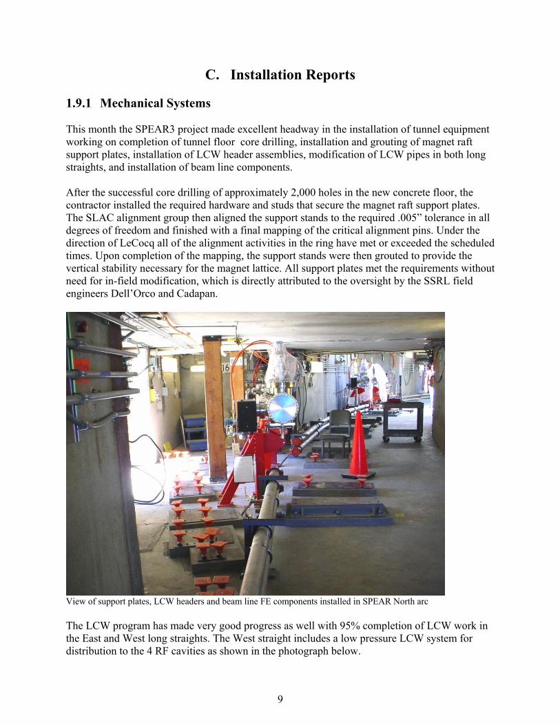
C. Installation Reports 1.9.1 Mechanical Systems This month the SPEAR3 project made excellent headway in the installation of tunnel equipment working on completion of tunnel floor core drilling, installation and grouting of magnet raft support plates, installation of LCW header assemblies, modification of LCW pipes in both long straights, and installation of beam line components. After the successful core drilling of approximately 2,000 holes in the new concrete floor, the contractor installed the required hardware and studs that secure the magnet raft support plates. The SLAC alignment group then aligned the support stands to the required .005” tolerance in all degrees of freedom and finished with a final mapping of the critical alignment pins. Under the direction of LeCocq all of the alignment activities in the ring have met or exceeded the scheduled times. Upon completion of the mapping, the support stands were then grouted to provide the vertical stability necessary for the magnet lattice. All support plates met the requirements without need for in-field modification, which is directly attributed to the oversight by the SSRL field engineers Dell’Orco and Cadapan.
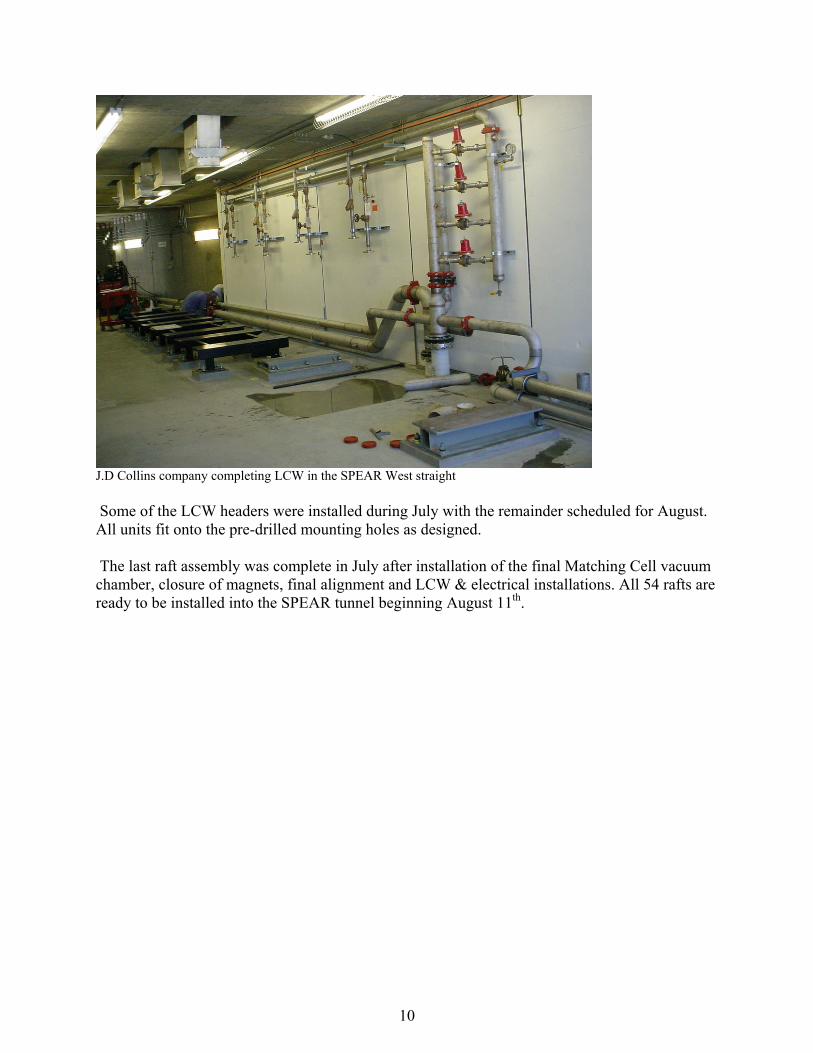
View of support plates, LCW headers and beam line FE components installed in SPEAR North arc The LCW program has made very good progress as well with 95% completion of LCW work in the East and West long straights. The West straight includes a low pressure LCW system for distribution to the 4 RF cavities as shown in the photograph below.
10
J.D Collins company completing LCW in the SPEAR West straight Some of the LCW headers were installed during July with the remainder scheduled for August. All units fit onto the pre-drilled mounting holes as designed. The last raft assembly was complete in July after installation of the final Matching Cell vacuum chamber, closure of magnets, final alignment and LCW & electrical installations. All 54 rafts are ready to be installed into the SPEAR tunnel beginning August 11th.
11
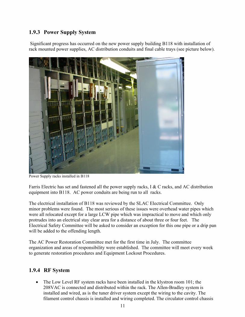
1.9.3 Power Supply System Significant progress has occurred on the new power supply building B118 with installation of rack mounted power supplies, AC distribution conduits and final cable trays (see picture below).
Power Supply racks installed in B118 Farris Electric has set and fastened all the power supply racks, I & C racks, and AC distribution equipment into B118. AC power conduits are being run to all racks. The electrical installation of B118 was reviewed by the SLAC Electrical Committee. Only minor problems were found. The most serious of these issues were overhead water pipes which were all relocated except for a large LCW pipe which was impractical to move and which only protrudes into an electrical stay clear area for a distance of about three or four feet. The Electrical Safety Committee will be asked to consider an exception for this one pipe or a drip pan will be added to the offending length. The AC Power Restoration Committee met for the first time in July. The committee organization and areas of responsibility were established. The committee will meet every week to generate restoration procedures and Equipment Lockout Procedures. 1.9.4 RF System
• The Low Level RF system racks have been installed in the klystron room 101; the 208VAC is connected and distributed within the rack. The Allen-Bradley system is installed and wired, as is the tuner driver system except the wiring to the cavity. The filament control chassis is installed and wiring completed. The circulator control chassis

12
and klystron focus power supplies are installed and wired. The VXI crate and the IOC and Scanner modules have also been installed. The waveguide has been installed from the klystron to the tunnel roof penetrations; all Magic-Tee assemblies and water loads have been installed on their support frames, although not yet bolted to the tunnel roof. The klystron water system installation has started and a supply bypass valve and hoses installed. The waveguide air pressurization system up to the loads is complete and the rest of the air system is still being worked on. Installation of the long haul cables from the RF racks to the cavities will be completed in August.
• Pulling and terminating of cables that interconnect all RF klystron power supply
components is complete. SSRL ES&H has asked for toe boards to be added to the power supply safety platform. These will be installed during the next reporting period.
• A purchase order was issued and installation of the secondary oil containment system has
begun. The secondary containment work is being monitored by the SLAC Environmental Safety Committee. The secondary containment installation will be followed by installation of a fixed stairway to the safety work platform.
• The chain link fence around the klystron power supply that is no longer needed and
would have presented interference and other issues was removed.
• The klystron power supply electrical installation was reviewed by SLAC Electrical Safety Committee. Only minor problems were found and have been corrected.
• Work continues on writing the klystron power supply Equipment Lockout Procedure
(ELP) and a commissioning test procedure. Efforts are also underway towards obtaining seismic qualification of the klystron power supply.
1.9.6 Cable Plant Installation
• The Cable Plant Phase 2 contracts which include: all the long haul cables for the project plus the ring trays and the ring tray supports were successfully bid and awarded. Cable installation begins in earnest on August 11. A short setup period for Palmer Electric, the winning contractor, will immediately precede the start-up.
• Cable Plant staff finished all cable and connector procurement for DC and I&C systems
and the supplied tray materials this reporting period. Ancillary needs, i.e. unistrut, clamps etc. will be addressed and procured as required throughout the installation.
• Design of the final assembly drawings for trays and DC jumpers was completed and
signed off immediately prior to inclusion in the bid.
• A report, listing non-tray rated cables needed but not otherwise available in rated form was submitted to the Electrical Safety Committee for approval.
13
1.9.8 Facilities All drawing have been completed for additional shielding that is now required by the Radiation Physics Committee for Phase 1 operation (Phase 1 is limited to 100 mA). This is required near the injection septum and kickers, beam stop, and at the transverse beam line exit walls. Apart form radiation shielding, consultants evaluated all existing roof shielding-blocks presently at SPEAR. Three very long blocks with cracks were questioned. Per the consultants assessment none of the three will collapse under the present loading conditions. However, no additional or new loads can be added and extra care needs to be taken when handling blocks in the future. It was recommended that the three be replaced in the future when they are to be removed from SPEAR for any purpose. All that attended the meeting agreed that new blocks sould be cast and stored inside the ring courtyard for possible replacement in the future.
14
2.0.2 Survey and Alignment Summary of the Alignment Engineering Group’s progress and accomplishments during the month of July:
• Templates: Through the first 3 days of July, all remaining beam line templates were marked with their holes color sprayed. The template activities started June 26 and ended July 3.
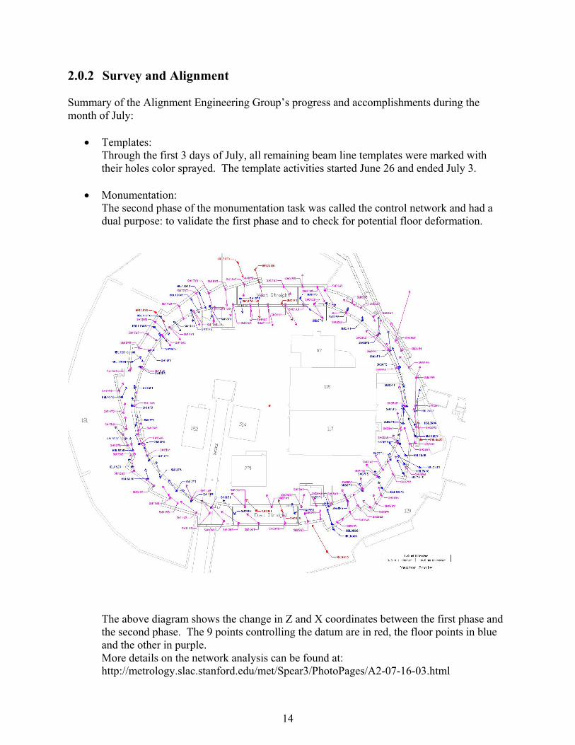
• Monumentation: The second phase of the monumentation task was called the control network and had a dual purpose: to validate the first phase and to check for potential floor deformation.
The above diagram shows the change in Z and X coordinates between the first phase and the second phase. The 9 points controlling the datum are in red, the floor points in blue and the other in purple. More details on the network analysis can be found at: http://metrology.slac.stanford.edu/met/Spear3/PhotoPages/A2-07-16-03.html
15
• Support Plate Alignment: The setting of the plates started on July 21 in the East Straight area progressing towards the north. One station in the middle of the girder was used to position 3 cell plates up stream, 3 cell plates down stream and any nearby straight pins, the controlling holes for yaw and a surface scan of the plates followed closely. Plots for horizontal position and height were generated to decide if the setting was acceptable. Plates out of tolerance were then reset using a special total station set-up. See for example: http://www-group.slac.stanford.edu/met/align/spear3/SP3Plate2/pdf All the plates were released for grouting August 1. An additional tracker survey of girder 11 was made to confirm the results established in Building 750 showing that the grouting did not change the position and attitude of the plates. In summary, 144 plates (108 cells, 21 straights and 15 others) were set and mapped.
• Building 750 raft assembly: The fiducialization data for the 2 BM1/MCB chambers were reanalyzed and the datum was changed to put the DS flange within 20 mil. Rafts 81 and 82 were “final aligned” accordingly.
• SSRL Beam-line (BL)Vacuum front end assembly: - CMM fiducialization of fixed masks for BLs 4, 6, 7, 9, 10, 11 - Union of fixed mask and movable mask for BLs 4, 6, 7, 9, 10 - Union of collimator and stopper for BLs 1, 2, 3, 6, 8
• Miscellaneous: - IR12: mapped support plate holes and magnet TBs. - Building 26: set the ID4 and ID7 chambers inside the wiggler. - BTS: set the caps to nominal height and marked the bolt pattern for later raft
installation. Daily summary report with occasional pictures can be obtained at: http://www-group.slac.stanford.edu/met/Align/Spear3/Spear3.html