Embed Size (px)
Citation preview
Doc. File: ICD_5.1 PAN Config_v1_0.doc Created on 8/17/2006 Doc. Number MNSN-AD-01-0007
Page 1 of 27
_______________________________________________________________________________________
NATIONAL OPTICAL
MAJOR INSTRUMENTATION GROUP 950 N. Cherry Ave.
ASTRONOMY OBSERVATORY
P. O. Box 2673 Tucson, Arizona 85726-6732
(520) 318-8000 FAX: (520) 318-8303
MONSOON PAN Run-time Configuration, Setup
and Operating Mode Definition Interface Description
NOAO Document ICD 5.1 Revision: 1.0
This document may or may not include all pertinent information. The final released version is forthcoming.
Authored by: Nick C. Buchholz and Phil N. Daly
12/4/2003 Please send comments: [email protected]

Doc. File: ICD_5.1 PAN Config_v1_0.doc Created on 8/17/2006 Doc. Number MNSN-AD-01-0007
Page 2 of 27
Revision History Version Date
Approved Sections Affected Remarks
0.1.1 12/4/2003 All Second release draft 1.0 (Provisional) 8/17/2006 All Reformatted and edited - aro

Doc. File: ICD_5.1 PAN Config_v1_0.doc Created on 8/17/2006 Doc. Number MNSN-AD-01-0007
Page 3 of 27
Table of Contents Revision History .................................................................................................................2 Table of Contents ...............................................................................................................3 List of Figures.....................................................................................................................4 List of Tables ......................................................................................................................4 1.0 Introduction...............................................................................................................5
1.1 Scope.........................................................................................................................5 1.2 Purpose.....................................................................................................................6 1.3 Acronyms and Glossary..........................................................................................6 1.4 Standard Terminology..........................................................................................10 1.5 What’s in This Document.....................................................................................11 1.6 What’s NOT in This Document ...........................................................................11
2.0 PAN Software Setup ...............................................................................................12 3.0 Configuration Techniques, General Requirements and Philosophy..................12
3.1 Shared Libraries – System Library Changes .....................................................13 3.2 Detector Specific Commands amnd Methods ....................................................13 3.3Configuration Files - .arr, .cfg, .gui........................................................................13
4.0 Initialization, Setup and observation/Exposure Modes.......................................14 4.1 Initialization Record - .ini ....................................................................................14 4.2 Setup Records - .mod, .ucd, .txt ...........................................................................14
5.0 The Detector Command Library - libDetCmnds.................................................14 5.1 libDetCmnds – Required Functions ....................................................................14
6.0 The Detector/Focal Plane Descriptor Record – xxx.arr ......................................18 7.0 The PAN/DHE Attribute Description Record – xxx.csv .....................................18 8.0 The GUI Interface Configuration Record – xxx.guiCategories.txt....................18 9.0 The Initialization Record – xxx.ini ........................................................................18 10.0 The Setup Routines – xxx_DefaultSetup.mod......................................................18 11.0 Observation and Exposure Modes –
xxx_Exp.mod, xxx_Idp.mod, xxx_SeqV00#.ucd ..................................................18
Appendix I Commands and Defined Variables and Parameters.............................19
Appendix II Attribute-Value Pair Notation Conventions..........................................23
Appendix III Configuration File Format ......................................................................24
Appendix IV Memory Configuration File Format ......................................................26

Doc. File: ICD_5.1 PAN Config_v1_0.doc Created on 8/17/2006 Doc. Number MNSN-AD-01-0007
Page 4 of 27
List of Figures
Figure 1 – Observatory Reference Model One .............................................................5 Figure 2 – MONSOON Context Diagram...................................................................12
List of Tables
Table 1 – Commands and Defined Variable and Parameters......................................19

1.0 Introduction
1.1 Scope The Generic Pixel Server Interface, as discussed at the November 2001 ACCORD conference, describes an interface between an image acquisition system or pixel server and the external world. The definition describes the interface between the instrument or observatory control system and the electronics and software which configure the detector, generate and preprocess the data, and send the data to an archive for later analysis.
The PAN Communications and Command ICD is a subset of the GPX commands which simplify the decomposition of the GPX in cases where more than one system communicates with the low level pixel generation hardware, that is, in mosaic requiring multiple detector controllers.
One of the basic requirements placed on the MONSOON project software was that the resulting programs should be configurable at run-time to appropriately describe and control any focal plane controlled by a MONSOON image server system.
This document delineates the interface, formats and methods used to do this run-time configuration and the formats and methods required to initialize and setup operating modes in the PAN/DHE software.
Observatory System Reference Model One
Observatory System Reference Model One Figure 1
Doc. File: ICD_5.1 PAN Config_v1_0.doc Created on 8/17/2006 Doc. Number MNSN-AD-01-0007
Page 5 of 27

Doc. File: ICD_5.1 PAN Config_v1_0.doc Created on 8/17/2006 Doc. Number MNSN-AD-01-0007
Page 6 of 27
1.2 Purpose This Interface Control Document (ICD) serves four purposes:
• To describe the run-time configuration system of the MONSOON PAN software.
• To describe the method used to initialize the parameters required by the software.
• To describe the method used to define operation Modes for a particular focal plane.
• To describe the behaviour of the run-time configuration system and the initialization system used by the PAN software.
The intended audience for this document is:
• The NEWFIRM instrument group.
• The developers of any Instrument which plans to use a MONSOON Pixel Server System.
• The MONSOON Pixel Server System group.
1.3 Acronyms and Glossary
1.3.1 Abbreviations and Acronyms
AC Acquisition Camera ADC Analog to Digital Converter DAC Digital to Analog Converter DCS Detector Controller System (software) DHE Detector Head Electronics DHS Data Handling System ECS Enclosure Control System ES Embedded System FITS Flexible Image Transport System FP Focal Plane FPA Focal Plane Array GPX Generic Pixel Server IAS Image Analysis System ICS Instrument Control System IDPS Image Data Preprocessor System ID Identifier IR Infrared LAN Local Area Network MONSOON Not an acronym NICD NOAO Interface Control Document N/A Not Applicable OCS Observatory Control System PDF Parameter Description File ROI Region of Interest SUS Status Update System TBD To Be Decided
Doc. File: ICD_5.1 PAN Config_v1_0.doc Created on 8/17/2006 Doc. Number MNSN-AD-01-0007
Page 7 of 27
1.3.2 Glossary
Attribute An entity that describes some aspect of the configuration of a Detector Head Electronics, Image Acquisition System or science instrument. Examples are: the name of a filter, a DAC voltage value, or the tilt angle of a grating. Some attributes will be used by the Instrument Control System as command parameters. The OCS communicates with a science instrument by sending it sets of attributes and values.
Byte 8 bits.
Command An instruction requiring a system to start some action. The action may result in a voltage changing or some internal parameters being set to particular values. A command may have command parameters (arguments) that contain the details of the instruction to be obeyed.
Data Array The data, while it is stored in data processing memory, which resulted from one or more readouts of an IR array or CCD detector.
Data Set A self-contained collection of data generated as a result of a Pixel Server obeying a gpxStartExp command. Each gpxStartExp command results in one and only one data set.
Detector Head Electronics
The lowest level hardware system, normally closely connected to the detector and the dewar in which the detector resides. Sometimes referred to as the Detector Controller.
Exposure The process and the data resulting from the process of resetting or clearing a detector, exposing it to photons and then reading one or more frames to determine the photon levels. These frames are processed into a data array, called an exposure, which may be further processed. For example, an exposure would be the data array that results when a single Reset-Readout-Integrate-Readout cycle is performed on an IR detector or a single CCD Clear-Integrate Readout cycle.
Frame The result of a single readout of an array. Each frame represents the signal values obtained from reading the entire ROI being read out of the detector. Multiple frames may be processed into a single exposure.

Doc. File: ICD_5.1 PAN Config_v1_0.doc Created on 8/17/2006 Doc. Number MNSN-AD-01-0007
Page 8 of 27
1.3.2 Glossary (Cont.)
Generic Pixel Server (GPX)
A set of software routines that implement a pixel server. A Generic Pixel Server does not require any particular set of proprietary hardware or software.
Image The array of detector pixel and description data representing a science or diagnostic exposure or combined set of exposures. An image is capable of being displayed or processed as a discrete entity. The values in the array may be stored in memory or on disk and are related to the data taken by the detector by some processing algorithm. For example, an image may consist of all the co-added and averaged exposures in one beam of a chop mode gpxStartExp command.
Image Acquisition System
A system of software and hardware capable of producing images from a detector on command.
Image Server A system of software and hardware capable of producing images from a detector on command.
Instrument Control System
A set of software routines designed to control and configure a science instrument to take science observations.
MONSOON Image Acquisition System
A Generic Pixel Server. An extensible, modular Image Acquisition System. The design of the system is, to the extent possible, independent of the hardware being used in a particular implementation. Each component of the system should be capable of replacement by a similar component without having to redesign the rest of the system. Each component of the software is, as far as possible, independent of the underlying hardware and as modular as possible.
Observation The process of exposing the detector to photons through the telescope in one or more exposures. The result of an observation is an image.
Pixel Acquisition Node
The computer that handles the interface to the Detector Head Electronics and the image pre-processing of the data stream from the Detector Head Electronics.
Pixel Server A set of software and hardware that accepts commands and produces a set of pixels (an image) related to those commands.
Read When used as a noun to describe instrument data, a single read of a pixel on the detector. A read may consist of several A/D conversions of the pixel data that are averaged or processed in some other way to produce a single integer output value for the pixel. A readout is made up of one read of each pixel in the detector ROI being read.

Doc. File: ICD_5.1 PAN Config_v1_0.doc Created on 8/17/2006 Doc. Number MNSN-AD-01-0007
Page 9 of 27
1.3.2 Glossary (Cont.)
Readout When used as a noun to describe instrument data, a single read of every pixel on the detector. A frame is made up of one or more readouts averaged pixel by pixel.
Region of Interest (ROI)
A sub-array of the available detector area. There are two types of sub-arrays that can be defined. The Sequence ROI is an ROI on the active surface of the array used to increase the frequency of the array readout. The Data Reduction ROI is an arbitrary rectangle of any size that fits on the array. Data Reduction ROIs are defined to reduce the volume of data sent to the disk or DHS even when the entire array is being read out.
Value The value associated with an attribute.
Word Four bytes or 32 bits.
1.3.3 Reference Documents
SPE-C-G0037, “Software Design Description”, Gemini 8m Telescopes Project.
WHT-PDF-1, “FITS headers for WHT FITS tapes”, Steve Unger, Guy Rixon & Frank Gribbin, RGO.
NOST 100-1.0, “Definition of the Flexible Image Transport System (FITS)”, NASA Office of Standards and Technology.
GEN-SPE-ESO-00000-794, “ESO Data Interface Control Document”, Miguel Albrecht, ESO.
IEEE Std 610.12-1990 - “IEEE Standard Glossary of Software Engineering Terminology”, Standards Coordinating Committee of the IEEE Computer Society, USA, 19901210.
ANSI/IEEE Std 754-1985 - “IEEE Standard for Binary Floating-Point Arithmetic” - Standards Committee of the IEEE Computer Society, USA 19850812
xxxx “XDR - Extended data representation Standard” ????
NOAO Document MNSN-AD-01-0002 - ICD 4.0 Version 1.0 - Generic Pixel Server, Communications, Command/Response and Data Stream Interface Description”, Nick C. Buchholz (NOAO), Barry M. Starr (NOAO), 8/8/2006
NOAO Document MNSN-AD-01-0003 - ICD 5.0 Version 1.0 - PAN Communications, Command/Response and Data Stream Interface Description, Nick C. Buchholz (NOAO), Phil N.Daly (NOAO), 8/15/2006
NOAO Document MNSN-AD-01-0004 - ICD 6.0 Version 1.0 - Generic Detector Head Electronics Command and Data Stream Interface Description, Nick C. Buchholz (NOAO), Barry M. Starr (NOAO), 8/9/2006
NOAO Document MNSN AD-01-0005 - ICD 6.1 Version 1.0 - Monsoon Detector Head Electronics- Command and Hardware Interface Description, Nick C. Buchholz (NOAO), Barry M. Starr (NOAO), 7/25/2006

Doc. File: ICD_5.1 PAN Config_v1_0.doc Created on 8/17/2006 Doc. Number MNSN-AD-01-0007
Page 10 of 27
1.4 Standard Terminology To avoid confusion and to make very clear what the requirements for compliance are, many of the paragraphs in this standard are labelled with keywords that indicate the type of information they contain. The keywords are:
• RULE
• RECOMMENDATION
• SUGGESTION
• PERMISSION
• OBSERVATION
These keywords are used as follows:
RULE <Paragraph Number> Subject Describing Text RULE
RULEs form the basic framework of this draft standard. They are sometimes expressed in text form and sometimes in the form of figures, tables or drawings. All RULEs shall be followed to ensure compatibility between components. All RULEs use the “shall” or “shall not” words to emphasize the importance of the RULE.
Example: 3.5 Status and Data Stream Interface RULE
RECOMMENDATION <Paragraph Number> Subject Describing Text RECOMMENDATION
Wherever a recommendation appears, designers would be wise to take the advice given. Doing otherwise might result in some awkward problems or poor performance. It is possible to design a system that complies with all the RULEs but has poor performance. Recommendations found in this standard are based on this kind of experience and are provided to designers to speed their traversal of the learning curve. All recommendations use the “should” or “should not” words to emphasize the importance of the recommendation.
Example: 2.5.1 GPX Names RECOMMENDATION
SUGGESTION <Paragraph Number> Subject Describing Text SUGGESTION
A suggestion contains advice that is helpful but not vital. The reader is encouraged to consider the advice before discarding it. Some design decisions that should be made are difficult until experience has been gained. Suggestions are included to help a designer who has not yet gained this experience.
Example: 2.5.2 Long Variables Names

Doc. File: ICD_5.1 PAN Config_v1_0.doc Created on 8/17/2006 Doc. Number MNSN-AD-01-0007
Page 11 of 27
PERMISSION <Paragraph Number> Subject Describing Text PERMISSION
In some cases, a RULE does not specifically prohibit a certain design approach, but the reader might be left wondering whether that approach might violate the spirit of the RULE or whether it might lead to some subtle problem. Permissions reassure the reader that a certain approach is acceptable and will cause no problems. All permissions use the “may” word to emphasize the importance of the permission.
Example: 2.6 Long Variables Names PERMISSION
OBSERVATION <Paragraph Number>Subject Describing Text OBSERVATION
Observations do not offer any specific advice. They usually follow naturally from what has just been discussed. They spell out the implications of certain RULEs and bring attention to things that might otherwise be overlooked. They also give the rationale behind certain RULEs so that the reader understands why the RULEs shall be followed.
Example: 2.7 Long Variables Names OBSERVATION
1.5 What’s in this Document This document presents the methods and procedures used to configure, initialize and control the PAN command set and attributes. It includes the requirements for configuration records and a description of the interface. It also includes a procedure which can be used to create a new configuration file, Initialization and setup file set. Finally, the document describes the procedure for describing and developing Observing/exposure modes for use with new focal planes.
1.6 What’s NOT in this Document This document does not describe the internal command and communications protocols or the nature of the internal command passing techniques. In particular, the hardware interconnects and data passing techniques within a PAN software are explicitly excluded from this discussion.
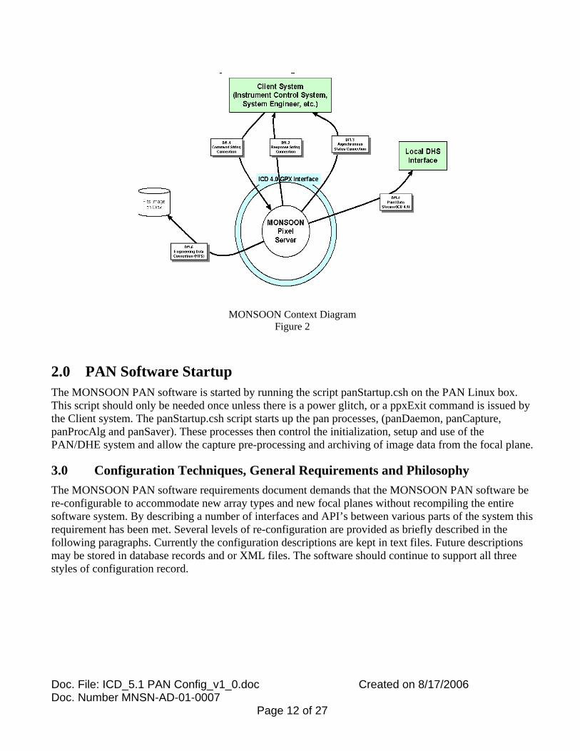
MONSOON Context Diagram
Figure 2
2.0 PAN Software Startup The MONSOON PAN software is started by running the script panStartup.csh on the PAN Linux box. This script should only be needed once unless there is a power glitch, or a ppxExit command is issued by the Client system. The panStartup.csh script starts up the pan processes, (panDaemon, panCapture, panProcAlg and panSaver). These processes then control the initialization, setup and use of the PAN/DHE system and allow the capture pre-processing and archiving of image data from the focal plane.
3.0 Configuration Techniques, General Requirements and Philosophy The MONSOON PAN software requirements document demands that the MONSOON PAN software be re-configurable to accommodate new array types and new focal planes without recompiling the entire software system. By describing a number of interfaces and API’s between various parts of the system this requirement has been met. Several levels of re-configuration are provided as briefly described in the following paragraphs. Currently the configuration descriptions are kept in text files. Future descriptions may be stored in database records and or XML files. The software should continue to support all three styles of configuration record.
Doc. File: ICD_5.1 PAN Config_v1_0.doc Created on 8/17/2006 Doc. Number MNSN-AD-01-0007
Page 12 of 27

Doc. File: ICD_5.1 PAN Config_v1_0.doc Created on 8/17/2006 Doc. Number MNSN-AD-01-0007
Page 13 of 27
3.1 Shared Libraries - System Library Changes NOT RECOMMENDED The first, most comprehensive and least recommended configuration method is to rewrite the MONSOON system shared libraries. When the PAN software starts up, part of the load process includes the loading of the shared libraries which implement the basic routines used in the software. One method of re-configuring the software would be to modify these basic shared libraries. This is not recommended. The MONSOON shared libraries are being and have been thoroughly tested to insure they meet the API for the routines and work correctly within the MONSOON software. This testing is ongoing. While we try to avoid the use of side effects in routines, we can’t guarantee that changes will not have unintended consequences.
3.2 Detector Specific Commands and Methods - libdetCmnds COMMENTARY The next most flexible configuration method is the use of the detector command library. Each detector type and focal plane configuration can have a set of commands to do the unique basic tasks required in controlling the detector or focal plane. This library can adopt commands from the generic command library and modify only those commands which are unique to the focal plane. A complete description of the structure, contents and use of the libdetCmnds library is included in a later section.
3.3 Configuration Files - .arr, .cfg, .gui COMMENTARY Currently the software loads in three configuration records during the start-up process. These records, with the libdetCmnds library, are sufficient to configure the MONSOON PAN software to run most array and focal plane configurations. The details of these record formats and contents are described in later major section.
3.3.1 Focal Plane Description Record - the .arr file
This record contains a description of the geometry of the focal plane and the detectors which make it up. The information in this record will determine the size of buffers, the number of output channels in the focal plane and the general structure and layout of the focal plane.
3.3.2 PAN/DHE Attribute Description Record - the .cfg file This record is partially created by the Electronic or Detector Engineer doing the integration of the MONSOON DHE hardware and the detector Focal Plane and partially by the software integrator. It contains a table of values which describe all of the settable attributes in the PAN/DHE system and gives meaningful names to DHE attribute functions; such as SEQ_LOOP_REG[1] in the DHE might be defined as rows2read in the PAN and clients.

Doc. File: ICD_5.1 PAN Config_v1_0.doc Created on 8/17/2006 Doc. Number MNSN-AD-01-0007
Page 14 of 27
3.3.3 The GUI Interface Configuration Record - the .gui file This record contains a list of category names which describe groups of attributes to be provided by the engineering or science client GUI. These groups are determined by the hardware integrator and or the Science instrument team.
4.0 Initialization, Setup and Observation/Exposure Modes Once the software is running and properly configured the Client program can initialize the system, set up the detector/focal plane parameters and set up observation and exposure modes for the focal plane and detectors. To do this the client system sends the GPX the gpx[ppx]SetMode or gpx[ppx]SetSysCfg commands. These commands use the record name on the command line or the record name set into the appropriate PAN attribute to initialize or setup the PAN-DHE pair.
The set mode commands may be used multiple times to initialize the setup or to refine a previously loaded mode.
4.1 Initialization Record - .ini
4.2 Setup Records - .mod, .ucd, .txt
5.0 The Detector Command Library -libDetCmnds The detector command library is a library built for each focal plane which encapsulates the unique details required to run the focal plane in question. The library contains a set of commands which must appear in the library and my contain command names which are unique to a particular detector or focal plane. The standard commands are explained below. Each detector specific library MUST include all of the commands listed in the required commands section and may use the generic versions or focal plane specific versions of the commands.
5.1 libDetCmnds - Required Functions
5.1.1 Hardware Attribute Commands These commands are the commands used to set and read back attributes in the DHE and PAN hardware. The current set of methods is compiled into the detector specific library. If no new methods are created, then only the detector library need be changed to change the set readback behavior of the PAN/DHE. If new commands are added (recommended only when required), then the additional commands will require changes to the cmdCfgUtil library code to reflect these additional commands. Note that this should only be required in cases where a significant change is instituted in the underlying MONSOON DHE hardware.

Doc. File: ICD_5.1 PAN Config_v1_0.doc Created on 8/17/2006 Doc. Number MNSN-AD-01-0007
Page 15 of 27
5.1.1.1 setBiasV, getBiasV void setBiasV ( long *istat, char *resp, ulong func, cmdTblP attAddr, char *attValue, ulong dheState);
void getBiasV ( long *istat, char *resp, ulong func, cmdTblP attAddr, char *attValue, ulong dheState);
5.1.1.2 setfBias, getfBais void setFBias ( long *istat, char *resp, ulong func, cmdTblP attAddr, char *attValue, ulong dheState);
void getFBias ( long *istat, char *resp, ulong func, cmdTblP attAddr, char *attValue, ulong dheState);
5.1.1.3 setImageName, getImageName void setImageName ( long *istat, char *resp, ulong func, cmdTblP attAddr, char *attValue, ulong dheState);
void getImageName ( long *istat, char *resp, ulong func, cmdTblP attAddr, char *attValue, ulong dheState);
5.1.1.4 setIntTime, getIntTime void setIntTime ( long *istat, char *resp, ulong func, cmdTblP attAddr, char *attValue, ulong dheState);
void getIntTime ( long *istat, char *resp, ulong func, cmdTblP attAddr, char *attValue, ulong dheState);
5.1.1.5 noMethod void noMethod ( long *istat, char *resp, ulong func, cmdTblP attAddr, char *attValue, ulong dheState);
5.1.1.6 setRdMskWrt, getRdMskWrt void getRdMskWrt ( long *istat, char *resp, ulong func, cmdTblP attAddr, char *attValue, ulong dheState);
void setRdMskWrt ( long *istat, char *resp, ulong func, cmdTblP attAddr, char *attValue, ulong dheState);
void _dheSetRdMskWrt(long *istat, char *resp, cmdTblP attAddr, char *attValue);
void _dheGetRdMskWrt(long *istat, char *resp, cmdTblP attAddr, char *attValue);
5.1.1.7 setRoiCols, getRoiCols void setRoiCols ( long *istat, char *resp, ulong func, cmdTblP attAddr, char *attValue, ulong dheState);
void getRoiCols ( long *istat, char *resp, ulong func, cmdTblP attAddr, char *attValue, ulong dheState);
5.1.1.8 setRoiRows, getRoiRows void setRoiRows ( long *istat, char *resp, ulong func, cmdTblP attAddr, char *attValue, ulong dheState);
void getRoiRows ( long *istat, char *resp, ulong func, cmdTblP attAddr, char *attValue, ulong dheState);
5.1.1.9 setSimple, getSimple, _panSetSimple, _dheSetSimple, _panGetSimple, _dheGetSimple void getSimple ( long *istat, char *resp, ulong func, cmdTblP attAddr, char *attValue, ulong dheState);
void setSimple ( long *istat, char *resp, ulong func, cmdTblP attAddr, char *attValue, ulong dheState);
void _panSetSimple(long *istat, char *resp, cmdTblP attAddr, char *attValue);
void _dheSetSimple(long *istat, char *resp, cmdTblP attAddr, char *attValue);
void _panGetSimple(long *istat, char *resp, cmdTblP attAddr, char *attValue);
void _dheGetSimple(long *istat, char *resp, cmdTblP attAddr, char *attValue);

Doc. File: ICD_5.1 PAN Config_v1_0.doc Created on 8/17/2006 Doc. Number MNSN-AD-01-0007
Page 16 of 27
5.1.1.10 setString, getString void setString ( long *istat, char *resp, ulong func, cmdTblP attAddr, char *attValue, ulong dheState);
void getString ( long *istat, char *resp, ulong func, cmdTblP attAddr, char *attValue, ulong dheState);
5.1.1.11 setVOffset, getVOffset void setVOffset ( long *istat, char *resp, ulong func, cmdTblP attAddr, char *attValue, ulong dheState);
void getVOffset ( long *istat, char *resp, ulong func, cmdTblP attAddr, char *attValue, ulong dheState);
void _dheSetVOffset(long *istat, char *resp, cmdTblP attAddr, char *attValue);
5.1.1.12 wrtToRead void wrtToRead ( long *istat, char *resp, ulong func, cmdTblP attAddr, char *attValue, ulong dheState);
5.1.2 Detector Specific Function Commands
5.1.2.1 detInit 5.1.2.2 detUninit 5.1.2.3 detAbortExp
void detAbortExp ( long *istat, char *resp );
5.1.2.4 detArmExpTrigger void detArmExpTrigger ( long *istat, char *resp );
5.1.2.5 detAsyncResp void detAsyncResp ( long *istat, char *resp, cmdTblP baddr);
5.1.2.6 detGetState void detGetState ( long *istat, char *resp, void *sPtr);
5.1.2.7 detPauseExp void detPauseExp ( long *istat, char *resp);
5.1.2.8 detPower void detPower ( long *istat, char *resp, ulong state, ulong sequence);
5.1.2.9 detReset void detReset ( long *istat, char *resp, ulong boards, ulong level);
5.1.2.10 detResumeExp void detResumeExp ( long *istat, char *resp);
5.1.2.11 detShftImg void detShftImg ( long *istat, char *resp, ulong shftX, ulong shftY);
5.1.2.12 detShutDown void detShutDown ( long *istat, char *resp);
5.1.2.13 detShutter void detShutter ( long *istat, char *resp);
5.1.2.14 detSimulate void detSimulate ( long *istat, char *resp, ulong system, ulong level);

Doc. File: ICD_5.1 PAN Config_v1_0.doc Created on 8/17/2006 Doc. Number MNSN-AD-01-0007
Page 17 of 27
5.1.2.15 detStartExp void detStartExp ( long *istat, char *resp);
5.1.2.16 detStopExp void detStopExp ( long *istat, char *resp);
5.1.2.17 detTestMode void detTestMode ( long *istat, char *resp, ulong testSuite, ulong level, ulong *result );
5.1.3 Detector Specific Data Handling Commands 5.1.3.1 detDescramble
void detDescramble ( long *istat, char *resp, long *src, int sPxlSize, long *dest, int dPxlSize);
5.1.3.2 detProcess void detProcess ( long *istat, char *resp, long *dest);
5.1.3.3 imgAdd void imgAdd (long *istat, char *resp, void *srcBuf, int sPxlSize, void *destBuf, int dPxlSize, long numPix);
5.1.3.4 imgSub void imgSub (long *istat, char *resp, void *srcBuf, int sPxlSize, void *destBuf, int dPxlSize, long numPix);
5.1.3.5 imgMov void imgMov (long *istat, char *resp, void *srcBuf, int sPxlSize, void *destBuf, int dPxlSize, long numPix);
5.1.3.6 detCalcPixels void detCalcPixels ( long *istat, char *resp, long *numPixels);
5.1.3.7 detCapture void detCapture ( long *istat, char *resp);
5.1.4 Internal Helper Commands - Provided in _generic 5.1.4.1 _cnvrtToDHE
void _cnvrtToDHE (long *istat, char *resp, cmdTblP attAddr, double fValue, ulong *dValue );
5.1.4.2 _cnvrtToPAN void _cnvrtToPAN (long *istat, char *resp, cmdTblP attAddr, ulong dValue, double *fValue );
5.1.4.3 _chkRange void _chkRange (long *istat, char *resp, cmdTblP attAddr, char *attValue );
5.1.4.4 _chkValue void _chkValue (long *istat, char *resp, cmdTblP attAddr, double fValue );

Doc. File: ICD_5.1 PAN Config_v1_0.doc Created on 8/17/2006 Doc. Number MNSN-AD-01-0007
Page 18 of 27
6.0 The Detector/Focal Plane Descriptor Record - xxx.arr
7.0 The PAN/DHE Attribute Description Record - xxx.csv
8.0 The GUI Interface Configuration Record - xxx_guiCategories.txt
9.0 The Initialization Record - xxx.ini
10.0 The Setup Routines - xxx_DefaultSetup.mod
11.0 Observation & Exposure Modes - xxx_Exp.mod, xxx_Idp.mod, xxx_SeqV00#.ucd

Doc. File: ICD_5.1 PAN Config_v1_0.doc Created on 8/17/2006 Doc. Number MNSN-AD-01-0007
Page 19 of 27
Appendix I Table 1 – Commands and Defined Variables and Parameters
Command Name
Parameters Set/Controlled
Usage/Explanation
ppxSetMode All parameters settable from other Config commands
numArrays An integer value giving the number of arrays in a focal plane. arrayDescriptor type rows columns outputsPerArray
A structure describing the characteristics of the array being controlled. The components are: a string giving the type of array, Two integers giving the size in rows and columns and an integer giving the number outputs on the array. Other elements may be needed for certain arrays.
outputArrangement picQueue baseR, baseC strideR, strideC chunkR, chunkC sizeR, sizeC
A structure which outlines how the array outputs are read. This includes a queue descriptor which tells where to place the pixels for processing and information on the structure of the pixel data block transferred. We describe the block of data as chunks of contiguous pixels separated by a intervening pixels from other blocks. The block is described by a number of integers giving the starting row and column of the block, a row and column stride (the number of pixels to skip when storing chunks) the row and column chunk size and the total size of the final block of data in rows and columns.
spcDescriptor gain settlingTime offset noiseFoM
A structure which describes the configuration of the signal processor chains in the system. The components of the structure are floating point arrays which describe the gain, settling time, and offset of the signal processing chain. Included is a noise figure of merit (TBD) which will allow the quietest set of chains to be chosen when that is important.
waveForms A descriptor for the timing waveforms to be run when running the array. These will be an array of bytes which will either describe of define the timing of the array readout. It is expected that each system will have an idiosyncratic way of describing these waveforms.
DacValueN - float An array of floating point voltage values which are to be loaded into any DAC settable voltages used to control the array. Each system will likely have a unique set of these voltages and a mapping from voltage name to DAC number should be provided in the PPX.
Min Integration Time
A floating point number giving the minimum integration time achievable by the system.
ppxSetArrConfig
Base Readout Time A floating point number giving the fastest possible readout time for the entire array.
Doc. File: ICD_5.1 PAN Config_v1_0.doc Created on 8/17/2006 Doc. Number MNSN-AD-01-0007
Page 20 of 27
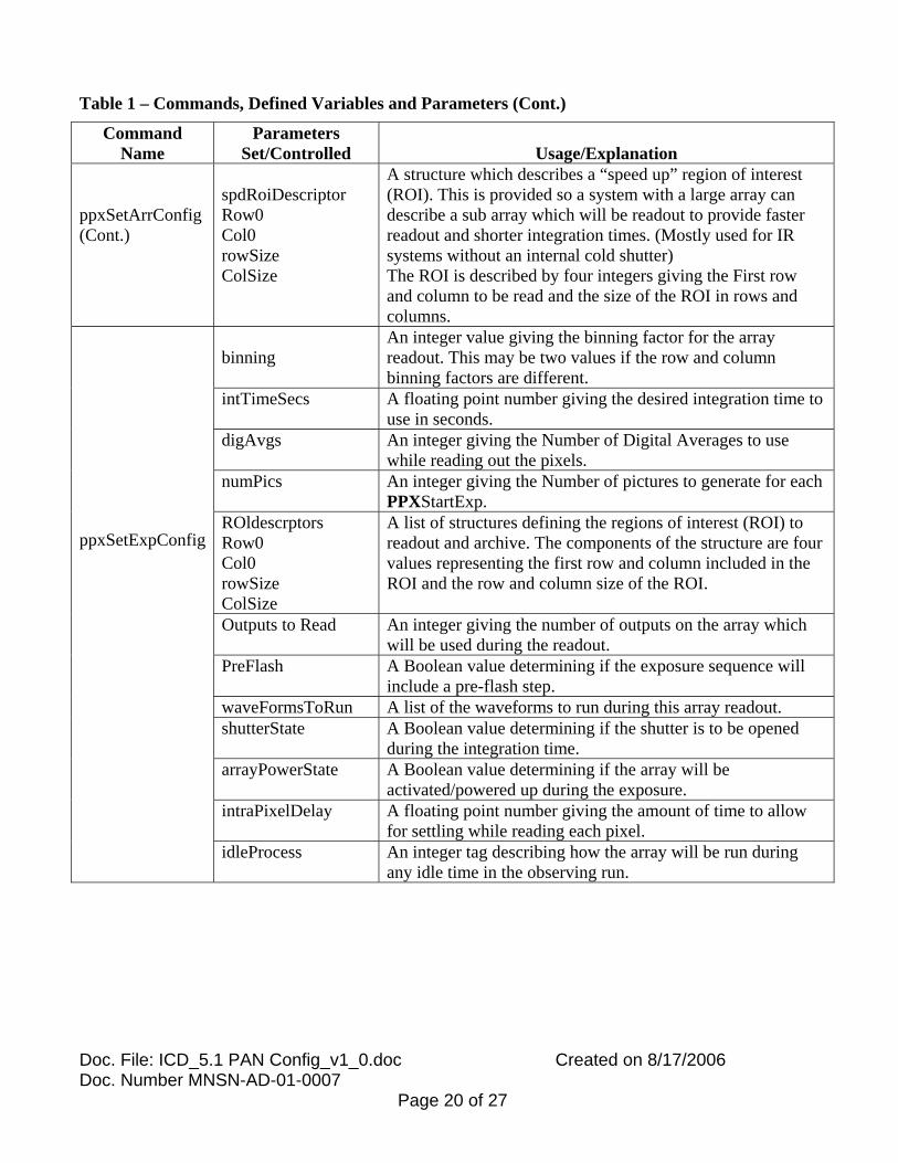
Table 1 – Commands, Defined Variables and Parameters (Cont.)
Command Name
Parameters Set/Controlled
Usage/Explanation
ppxSetArrConfig (Cont.)
spdRoiDescriptor Row0 Col0 rowSize ColSize
A structure which describes a “speed up” region of interest (ROI). This is provided so a system with a large array can describe a sub array which will be readout to provide faster readout and shorter integration times. (Mostly used for IR systems without an internal cold shutter) The ROI is described by four integers giving the First row and column to be read and the size of the ROI in rows and columns.
binning
An integer value giving the binning factor for the array readout. This may be two values if the row and column binning factors are different.
intTimeSecs A floating point number giving the desired integration time to use in seconds.
digAvgs An integer giving the Number of Digital Averages to use while reading out the pixels.
numPics An integer giving the Number of pictures to generate for each PPXStartExp.
ROldescrptors Row0 Col0 rowSize ColSize
A list of structures defining the regions of interest (ROI) to readout and archive. The components of the structure are four values representing the first row and column included in the ROI and the row and column size of the ROI.
Outputs to Read An integer giving the number of outputs on the array which will be used during the readout.
PreFlash A Boolean value determining if the exposure sequence will include a pre-flash step.
waveFormsToRun A list of the waveforms to run during this array readout. shutterState A Boolean value determining if the shutter is to be opened
during the integration time. arrayPowerState A Boolean value determining if the array will be
activated/powered up during the exposure. intraPixelDelay A floating point number giving the amount of time to allow
for settling while reading each pixel.
ppxSetExpConfig
idleProcess An integer tag describing how the array will be run during any idle time in the observing run.

Doc. File: ICD_5.1 PAN Config_v1_0.doc Created on 8/17/2006 Doc. Number MNSN-AD-01-0007
Page 21 of 27
Table 1 – Commands, Defined Variables and Parameters (Cont.)
Command Name Parameters Set/Controlled
Usage/Explanation
Data Disposition -struct disposition - procedure name Arguments - filename, directory image format, data type, data stream/queue
Pre-processing Algorithm
Unscrambling Algorithm
Image Data Set ID coAdds - integer
ppxSetIDPConfig
fSamples - integer ppxSetAVP Every user-settable
attribute
binning - Integer intTimeSecs – float digAvgs - integer numPics – integer shutterState arrayPowerState Data Disposition Pre-processing Algorithm
Unscrambling Algorithm
Image Data Set ID coAdds – integer
ppxStartExp
fSamples - integer TriggerSource ppxArmExpTrigger TriggerTime Out
ppxStop Image Data Set ID ppxAbort None ppxPause intTimeSecs – float ppxResume intTimeSecs – float ppxShutter Current shutter state
Row or Y shift ppxShft/Image Column or X shift

Doc. File: ICD_5.1 PAN Config_v1_0.doc Created on 8/17/2006 Doc. Number MNSN-AD-01-0007
Page 22 of 27
Table 1 – Commands, Defined Variables and Parameters (Cont.)
Command Name Parameters Set/Controlled
Usage/Explanation
ppxSimulate Units to simulate ppxTestMode Units to test ppxPower System Power State ppxReset System Reset Level ppxGetState Reads all system
state attributes
ppxGetAVP
Reads every individual system attribute
Reports asynchronous events and errors
ppxAsynchMsg
Asynchronously reports attribute values
ppxRstAsynStatus Resets asynchronous event and error flags
ppxPass
Passes string command to underlying system
Doc. File: ICD_5.1 PAN Config_v1_0.doc Created on 8/17/2006 Doc. Number MNSN-AD-01-0007
Page 23 of 27
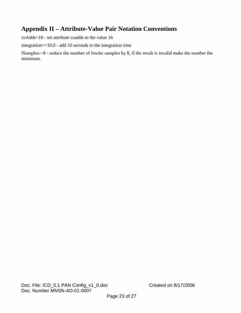
Appendix II – Attribute-Value Pair Notation Conventions coAdds=16 - set attribute coadds to the value 16
integration+=10.0 - add 10 seconds to the integration time
fSamples-=8 - reduce the number of fowler samples by 8, if the result is invalid make the number the minimum.
Doc. File: ICD_5.1 PAN Config_v1_0.doc Created on 8/17/2006 Doc. Number MNSN-AD-01-0007
Page 24 of 27
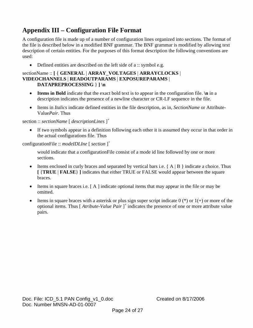
Appendix III – Configuration File Format A configuration file is made up of a number of configuration lines organized into sections. The format of the file is described below in a modified BNF grammar. The BNF grammar is modified by allowing text description of certain entities. For the purposes of this format description the following conventions are used:
• Defined entities are described on the left side of a :: symbol e.g.
sectionName :: [ { GENERAL | ARRAY_VOLTAGES | ARRAYCLOCKS | VIDEOCHANNELS | READOUTPARAMS | EXPOSUREPARAMS | DATAPREPROCESSING } ] \n
• Items in Bold indicate that the exact bold text is to appear in the configuration file. \n in a description indicates the presence of a newline character or CR-LF sequence in the file.
• Items in Italics indicate defined entities in the file description, as in, SectionName or Attribute-ValuePair. Thus
section :: sectionName [ descriptionLines ]+
• If two symbols appear in a definition following each other it is assumed they occur in that order in the actual configurations file. Thus
configurationFile :: modeIDLIne [ section ]+
would indicate that a configurationFile consist of a mode id line followed by one or more sections.
• Items enclosed in curly braces and separated by vertical bars i.e. { A | B } indicate a choice. Thus [ {TRUE | FALSE} ] indicates that either TRUE or FALSE would appear between the square braces.
• Items in square braces i.e. [ A ] indicate optional items that may appear in the file or may be omitted.
• Items in square braces with a asterisk or plus sign super script indicate 0 (*) or 1(+) or more of the optional items. Thus [ Atribute-Value Pair ]+ indicates the presence of one or more attribute value pairs.

Doc. File: ICD_5.1 PAN Config_v1_0.doc Created on 8/17/2006 Doc. Number MNSN-AD-01-0007
Page 25 of 27
The description of the Configuration File follows:
configurationFile :: modeIdLine fileSections
modeIdLine :: ModeName = FileName \n
fileSections :: [ generalSection array ] [ VoltageSection ] [ arrayClockSection ] [ videoChannelSection ] [ readoutParamsSection ] [ exposureParamSection ] [ dataPreProcessSection ]
generalSection :: [GENERAL] \n sectionLines
VoltageSection :: [ARRAYVOLTAGES] \n sectionLines
arrayClockSection :: [ARRAYCLOCKS] \n sectionLines
videoChannelSection :: [VIDEOCHANNELS] \n sectionLines
readoutParamSection :: [READOUTPARAMS] \n sectionLines
exposureParamSection:: [EXPOSUREPARAMS] \n sectionLines
dataPreProcessSection:: [DATAPREPROCESSING] \n sectionLines
sectionLines :: [ sectionConfigurationLines ]* [AttributeValueLines ]*
Doc. File: ICD_5.1 PAN Config_v1_0.doc Created on 8/17/2006 Doc. Number MNSN-AD-01-0007
Page 26 of 27
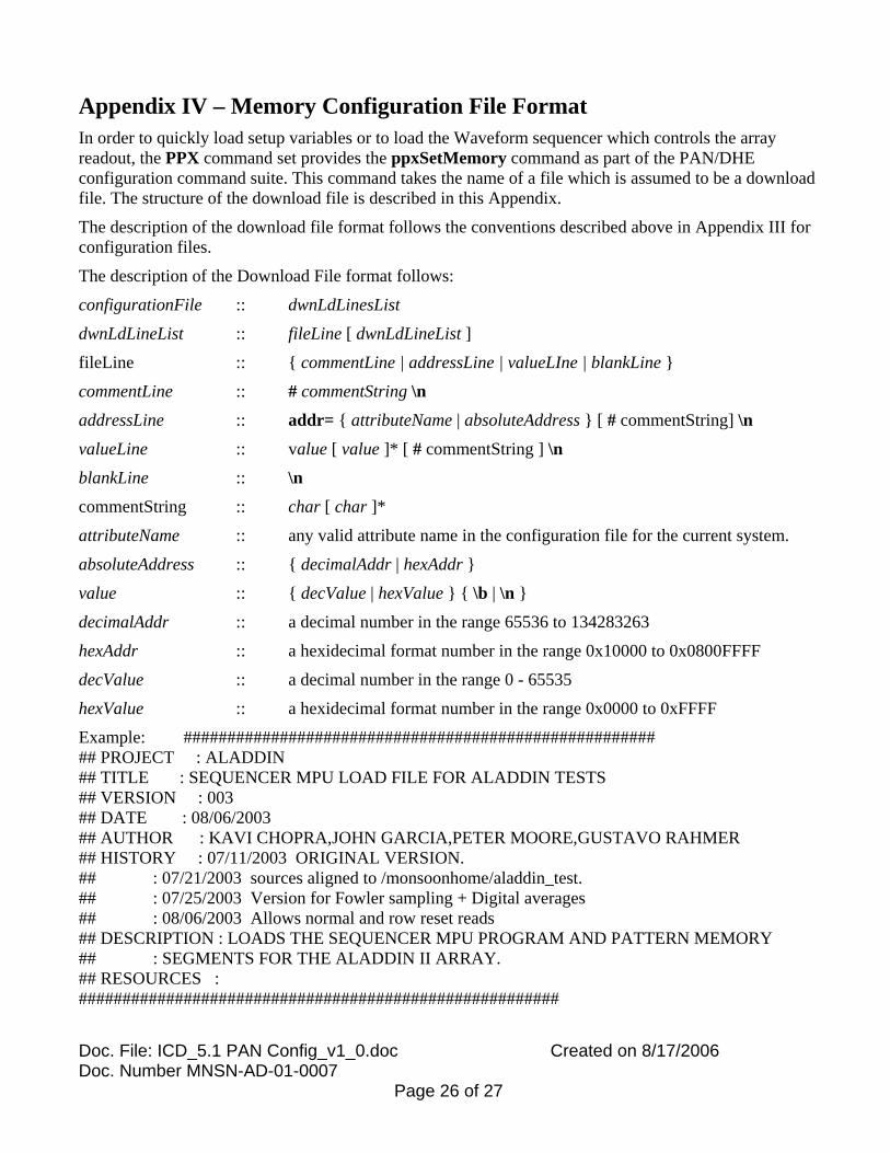
Appendix IV – Memory Configuration File Format In order to quickly load setup variables or to load the Waveform sequencer which controls the array readout, the PPX command set provides the ppxSetMemory command as part of the PAN/DHE configuration command suite. This command takes the name of a file which is assumed to be a download file. The structure of the download file is described in this Appendix.
The description of the download file format follows the conventions described above in Appendix III for configuration files.
The description of the Download File format follows:
configurationFile :: dwnLdLinesList
dwnLdLineList :: fileLine [ dwnLdLineList ]
fileLine :: { commentLine | addressLine | valueLIne | blankLine }
commentLine :: # commentString \n
addressLine :: addr= { attributeName | absoluteAddress } [ # commentString] \n
valueLine :: value [ value ]* [ # commentString ] \n
blankLine :: \n
commentString :: char [ char ]*
attributeName :: any valid attribute name in the configuration file for the current system.
absoluteAddress :: { decimalAddr | hexAddr }
value :: { decValue | hexValue } { \b | \n }
decimalAddr :: a decimal number in the range 65536 to 134283263
hexAddr :: a hexidecimal format number in the range 0x10000 to 0x0800FFFF
decValue :: a decimal number in the range 0 - 65535
hexValue :: a hexidecimal format number in the range 0x0000 to 0xFFFF
Example: ###################################################### ## PROJECT : ALADDIN ## TITLE : SEQUENCER MPU LOAD FILE FOR ALADDIN TESTS ## VERSION : 003 ## DATE : 08/06/2003 ## AUTHOR : KAVI CHOPRA,JOHN GARCIA,PETER MOORE,GUSTAVO RAHMER ## HISTORY : 07/11/2003 ORIGINAL VERSION. ## : 07/21/2003 sources aligned to /monsoonhome/aladdin_test. ## : 07/25/2003 Version for Fowler sampling + Digital averages ## : 08/06/2003 Allows normal and row reset reads ## DESCRIPTION : LOADS THE SEQUENCER MPU PROGRAM AND PATTERN MEMORY ## : SEGMENTS FOR THE ALADDIN II ARRAY. ## RESOURCES : #######################################################

Doc. File: ICD_5.1 PAN Config_v1_0.doc Created on 8/17/2006 Doc. Number MNSN-AD-01-0007
Page 27 of 27
# ALADDIN PATTERN MEMORY SEGMENT # First Give start address #addr=0x00011000 # you can use absolute address or #addr=MCB_SEQPATMEM # DHE attribute name or addr=mcbSeqPatMem # PAN attribute name # Now list the values to be loaded into the memory # you can list one per line or several per line 0x0001 0x0000 0x0002 0x0000 0x0004 0x0000 0x0000 0x0000 0x0000 0x0000 0x0000 0x0000 0x0000 0x0000 0x0000 0x0000 0x0000 0x0000 0x0000 0x0000 0x0000 0x0000 0x0000 0x0000 0x2540 53 32456 18