Embed Size (px)
Citation preview

Monographie BIPM-l
PROCEDURES FOR ACCURATELY DILUTING
AND DISPENSING RADIOACTIVE SOLUTIONS
1975
BUREAU INTERNATIONAL DES POIDS ET MESURES
Pavilion de Breteuil, F-92310 SEVRES

PROCEDURES FOR ACCURATELY DILUTING AND DISPENSING
RADIOACTIVE SOLUTIONS
Preface
This monograph is one of several to be published by the Bureau Internotionol des Poids et Mesures (B.I.P.M.) on beholfof the Comite Consultotif pour les Etalons de Mesure des Rayonnements lonisants (C.C.E.M.R.I.). The aim of this series of publications is to review various topics which are of importance for the , measurement of ionizing radiation and radioactivity, in particular, those techniques normally used by participants in international comparisons. It is hoped that these publications will prove to be useful reference volumes both for those who ore alreody engaged in this field and for those who are approaching such measurements for the first rime.
This volume is concerned with a particular aspect of radionuclide metrology and Was prepared for publication by P.J. Campion .
f
1 ,
E. Ambler J . Terrien C ha i rma n 0 f the C. C • E • M. R .1. Director af the B.I.P . M.

CONTENTS
Preface
Introduction
General requirements for weighing
Outline of procedures
Details of procedures: Issuing laboratory
The master solution
Dispensing the master solution
Details of procedures: Receiving laboratory
Dilution
Source preparation
Efficienc y tracer measurements
Uncertainties
Co nc I usio n
Appendi x 1 - C leaning treatment for glass and polyethylene
Appendix 2 - Water-repellent silicone coatings
Appendi x 3 - Preparation of polyethylene pycnometers
Appendix 4 - The buoyancy correction
Appendi x 5 - Ioni zation chamber measurements
References
Page
3
3
6
8
8
9
13
14
17
20
20
22
ve sse Is 23
24
25
26
28
29

3
INTRODUCTION
Ad vance s in metrolog y are usually made by concentrating on the reduction of the magnitude of the most significant source of potential error in a measurement to a value which is small compared with those of other source s; the process is then repeated with the ne xt most significant source and so on . Thus, a particular technique which may be good enough within a measuring sys tem which is capable of an accurac y of, say, + 2% ma y not be acceptable when all the other techniques in that system have been improved to a level of accurac y of + 0.2% . Hence techniques and procedures, which may be fou nd so tisfa c to-;y ot 0 given time, mu st be e xamined periodicall y in the light of advances made in the rest of the system . With the present stateof-the-ort of radioactivity metrolog y the two stages in the determination of radioactive co ncentration where errors are perhaps mo st likel y to occur (apart from the disintegration rate mea su rement of the indi v idual sources) a re (1) the dilution of a concentrated solution and (2) the dispensing of sma ll quantitie s of the diluted solution in the preparation of sources for cou nting. Technique s for the satisfactory accomplishment of both these man ipulations ha ve been described in the literature although a considerable amount of additiona"1 and detailed knowledge remains unpublished and is vested in many labo ra torie s th ro ug ho ut the world. Thi s monograph represents an attempt to pro vide a guide to what mig ht be called "good laboratory practice" in this area. Because not 011 laboratories agree on the best practice at e very point, a n attempt has been made to record variant procedures where the se have been made known to the outhor. It follows, therefore, that while ge ne ra 11 y agree i ng with th is re port, a 11 the me m be rs of C • C • E • M • R • I. do no t necessarily subscribe to all of its recommendations. It is hoped that the monograph will be of value to those engaged in the standardization of radioac ti vi ty , e speciall y those who ma y be approaching these problems for the first time .
GENERAL REQUIREMENTS FOR WEIGHING
It is generall y agreed that diluting and di spensing are best carried out gravimetrically and hence the fir st requirement is a balance capable of determining the ma ss of a liquid drop in the range la to 100 mg to an accurac y of better than + 20 jJ.-g. Such balonces are often limited in their capacity and it is thus convenient to have a second balance on which masses of the order of 50 g can be weighed and which need only have on accuracy of about ~ 200 P:g. It is important that the balances should b. located in a room that is relatively draught-fr •• and which should be large enough

4
to carry out simple manipu.lations other than weighing. Mechanical balances in particular shou ld rest on a rigid and heavy table, preferably on the bottom floor of a buildin g , the floor being in contact with compacted or undisturbed ground. Alternatively the table shou ld rest on brick or concrete piers with foundations in undisturbed ground. It is also important that balances should be regularlr cleaned and serviced. A small thermal gradient of the order of 0.1 K m- within the balance enclosure (top warmer) is e ssentia l for the stabi lit y of equal-arm type of balances, but due to basic di fference s in de sign, it is not usually necessa ry to impose such a gradient wi thin the enclosure of single-arm balances [lJ; it is good laboratory practice to locate the balances in a part of the balance room that has a positive thermal gradient (top warmer) because the general nature of the disturbing effects of having the top cooler is applicable to some degree to all types of precise balances. The temperature in the balance room should be both spatially uniform and constant preferably to within+0.50( over a short period, say one hour, and to within + 1 °C over a 24 hourperiod. The humidity shou ld also be reasonably c;nstant over t he same period, say with in + 5% at a relati ve humidity preferably in the range 50 to 60%. Such stability may be achieved by careful lo cation of the balance room (e .g. a room within a room, or a room with a very large thermal capacity) or by suitable air conditioning equipment. In the latter case it is particularly important to ensure tha t any v ibration of the air conditioning plant is not transmitted to the balance room. It is also desirable that the air be delivered to the balance room via a perforated fal se ceiling or similar widely dispersed ducting ports in order to attenuate air currents as much as possible. A procedure some times adopted is to switch off the air conditioning plant when actually carrying out weighi ng. Provided the balance room is well insulated, as it shou ld be , the temperature change over the period required for diluting and dispensing, say one ho ur, wi ll be negl igible and the desirable condi tions of a positive thermal gradient and minimal vibration will be realized. Accurate weighings can only be started if thermal equilibrium has been reached by the balance and its environment; some experts ·recommend that the operator shou ld sit in front of the balance for at least 15 minutes before weighing comme nce s in order to attain a sufficie nt degree of thermal equilibirum. Smoking should be prohibited in the balance room to reduce the possibility of tor and other products condensing on the balance mechanism. The temperature and humidity fluctuations for adjacent preparatory rooms may be somew hat greater but the mean values sho.uld be the same as those of the balance room in order to avoid long delays in vessels and solutions reaching equilibrium with the balance environment.
While the stabi lity of commercially available balance weights is normally adequate, very sma ll amounts of dirt will introduce errors and regular cleaning and recalibration of the weights is recommended. Even when re g ularl y cleaned, occasionally a weight has been observed to change its actual mass over a period of yea rs due, pre sumabl y , to a surfa ce chemical effect and sma ll but ne vertheless significant changes con take place over short periods for no obvious reason [2, 3J. It is therefore recommended that

5
the balance weights be calibrated, independently of the manufacturer, before being put into service and annuall y thereafter; this requires an access to professional mass metrolog y services. In principle this calibration can be achieved by a sing le reference weight, the fractional uncerta inty being the same for all the (smal le r) weights calibrated using the reference weight r 4J but in v iew of the possib le mass changes mentioned abo ve it is advisable to have several calibrated reference weights available. It should be noted that the response of a balance on its optical scale is not necessarily linear and thus the scale should al so be calibrated [3-6].
Apart from the calibration of the balance weights and optical scale the following tests should be carried out by the balance user whe n the balance is first installed and from time to time thereafter in order to assure himself that its performance has not deteriorated :
1. the variation of sensitivity over the optical scale
2. the variation of sensitivity with time, and eventuall y
3. test of randomness.
These and more e x tensive performance tests may be found in the literature [7-12].
Static charge may build up on glassware and plastic materials and can cause serious errors in weighing particularly when usi ng small balance enclosures [13J. These difficulties may be avoided by means of a radioac~tive static charge eliminator situated within the enclosure. The source may be a ~-emitter such as 204TI or 90S r_90y and in such cases, for safe ty reasons , a mechanical shutter is often arranged to close over the source when the balance enclosure is opened. On the other hand a-emitters are much more efficient eliminators of static charge and considerably weaker sources ma y be used without the necessity of a shutter [131, although with such emitters the experimenter sho uld be aware of the possibil ity of recoil contamination. In this respect the use of 210po should be avoided.
A most important requirement in the manipulation of both active and inacti ve solut ions is that 011 vesse ls used shall be scrupulous ly clean, and this also applies to the ampou le s into which the active solutions are fina ll y dispensed for distribution. Some typical methods for cleaning such vessels are described in Appendix 1. If required, clean glassware may be given a water-repe lie nt sit icone coating. This treatment is necessary for g la ss pycnometers, but is not recommended for ampoules since the coating is destroyed by flame sealing. Some laboratories coat other glassware such as dilution flasks, scintillatio n via ls, etc., whereas others recommend against this. Procedures for silicone-coatin g g la ss together with some advantages and disadvantages of doing so are given in Appendix 2. Pol yethyle ne is naturally hydrophobic, but adsorption or absorption has been observed to occur with palyethylene surfaces . Polyethylene is also porous to some solvents [ 14-18J.

6
OUTLINE OF PROCEDURES
The procedure s normally involved in di stributing a standard of radioactivity cnd in making an accurate acti v ity measurement are schematically i ll ustrated in the chart of Figure 1. Naturally the details ma y vary in an individual laboratory or for particular rodionuclides but in genera l Figure 1 represents the brood outline of the manipulations required.
In brief, the master so lution is di spensed into os mony ampoules os ma y be necessary for the intercomparison or distribution. A few of these ampoules are retained for the measurement of the activity per unit moss of solution and the remain i ng ampoules ore di stributed to laboratories participating in the intercomparison. Because the radioactive concentration of the master solution and the aliquot size are selected so that the filled ampoules provide a su itable ioni zation chamber re sponse to give a convenient measuring time (or contai n sufficient radioactivity for a particular pu rpo se) it is usually necessary to dilute the distributed so lution to a level which is suitable for making sources for counting. As wi ll be seen below, the dilution stage shou ld not introduce a significant error into the measurement of the radioactive conce ntration.
Having diluted the solution to 0 suitoble level the ne x t step is to prepare the counting sources. These will usually be dispensed either on to thin metal -coa ted VY NS · or other films for gas proportional counting or into suitab le vials for liquid scintillation counting . The solution is dispensed from a vessel (a pycnometer) and the mass deposited may be determined in two ways . In the first method the ma ss of the so lution deposited is obtained by weighing the pycnometer before and after dispensing the drop of solution and this is usually referred to as the pycnometer method. The second method invo lves the weighing of the source mount (or scintillation vial) before and after dispensing the drop of solution. To correct for the evaporation of the solution from an open source mount the mass of source mount plus solution is observed as 0 function of time and an extrapolation made to obtain the combined mass at the instant the drop was dispensed. This is cal led the e x trapolation method. Only by careful attention to detail can these two methods be made to agree; in general the pycnometer method is to be preferred and is recommended in this monograph. This is not to say that the e x trapolation method cannot be used successfu ll y but only that there is an inherent systematic error in the technique due to a non constant rate of evaporation near time zero [13, 22, 23J . In order to minimise the uncertainty due to this effect the use of on electrobalance is essential.
* VYNS is a copolymer of vinyl chloride and vinyl acetate. Details af the production and metallising af such films may be found in the lite rature
[19-21] .

PROCEDURE
Mast~r sotution dispensed into ampoul~s
Ampoul~s s~l.ct~
for measurement
Dilution
Preparation of la}
I I
MASTER
SOLUTION
I
('"'.2, " , IU\ . , . ,
I , I , , , , . , . , , , \ ' .... ---r --_ ...
Etc .-------,----'---,-.-... --.-,.--.--,. - ---
,'-----, ----" - v-
Ampoules for ion chamber measurements
C> C>
C>
'-----~v I
Ib) Sources for counting
I I I
, , r --_______ L _ ---
, ,
c- il ., \, .. )\..JI
• I •
I ' • I •
• , , / . \ ________ J
Figure 1 - Procedures for the distribution and preparation for measurement of radioactivity stonda rds
"

8
DETAILS OF PROCEDURES: ISSUING LABORATORY
The master solution
While a detailed discussion of the physical ond chemical composition of master solutions is beyond the scape of this monograph it is relevant to mention some of the more important factors which should be considered when specifying such solutions. The purpose for which a standard of radioactivity is required is one such factor which may influence the choice of chemical composition, appro x imate radioactive concentration, and perhaps, container. This monograph is mainly concerned with the use of solutions in international compari sons where considerations of accuracy are paramount, but for distributions fram standardizing laboratories other factors such as the specific application of the standard and even the cost may, in part, determine the choice of characteristics.
In general, the objective is to achieve a stable solution having negligible adsorption on container walls but at the same time having a low dissolved solids content in order that thin sources with as small a self-absorption as practicable may be prepared for 4rr counting. A re lated consideration is that both acid and alkaline solutions tend to leach out glass so increasing the concentration of disso lved solids [24-26J. This increase depends on the strength of acid or base in the solution, the type of glass forming the container and the length of time of contact; values of the order· of 100 f-l-g/ fI. of solids have been reported after several months of storage in Pyre x glass L 27J . Quartz is relatively insoluble and has been used far the storage of standard solutions r14,2S] and although polyethylene vessels are also good in this respect [26J they are slightly porous. Thus, if it is necessary to achieve the absolute minimum of dissolved solids, both reagents and water should be freshly distilled using quartz utensils·. However, the widespread use af the coincidence technique and its extension to the tracer method for pure ~ -emitters reduce the need for such e x treme measures and analytical grade reagents and water distilled in borosilicate stills are usually adequate .
• Typically, once-distilled water contains solids to the e x tent of about 1 f-"9/ g while triple distillation in quartz stills will reduce this by obout an order of magnitude. Triply-distilled and de ionized water contains solids to the extent of about 0.01 f-l-S / g [26J; however de ionized water is rarely free from organic matter. A recent review of the production of ultrapure water has been given in reference [28J .

9
Adsorption is another phenomenon that must be considered and the carrier concentration and the pH of the master so lution shou ld be chosen to minimise this; os a general guide a concentration of about 100 f.L'9 of ca rrier p':er gram of on acid (usua ll y Hel or HN03) solution of 0.1 mol in 1 dm 3 of water is acceptable but concentrations both above and below these guide line va lue s may be required for particular radionuclides. Some radionuc lide solutions are particularly susceptible to bacterial growth which can absorb activity from the so lution . In such cases the solutions should contain a bacteriostat such as 0.10/0 formalin or be heat sterilized after having been sea led in the ampoules. The latter is in any case considered to be a desirable practice if the ampoules are to be stored for a considerable length of time. A useful guide to the chemistry of vario us radionuc lide s in dilute so lutions has been pub li shed [29J .
It should be noted that radiolysis can produce an increase in pressure in closed vesse ls containing radioact"ive solutions. For radioactive concentrations of the order of 100]J.A:i per g ram of so lution the effect is usually negligible and sealed glass ampoules can be safely used for the long term storage of solutions. For large radioactive concentrations there is the danger of mechanical rupture (for e xample, a gram of solution containing an activitY.: of 10 mCi of an a-emitting nuclide will produce in six weeks about 1 cm 3 of gas at NTP due to radiolytic decomposition but even more important from the point of view of radionuclide metrology is the question of the chemical stabil ity of suc h so lutions.
The remarks made in the Introduction with regard to acceptable uncertai nty limits apply wi th equal emphasis to the radionuclide purity of the activity; this shou ld be checked using a method whose sensi ti vi ty is compatible wi th the overall uncertainty limits and, if necessary, chemical separations performed before preparing the master solution.
Dispensing the master solution
A number of glass or, if necessary, quartz ampoules wh ich can subsequently be flame sea led must be selected and prepared. Although the quantity of master solutio n dispensed into each ampoule is determined gravimetrically it is usuall y checked by means of measurements in a re-e ntrant , or well -type, ionization chamber; in some metrological laboratories use is made of Nal(Tl) or Ge(li) detectors for the comparison of activities. In order that the y-ray absorption properties of ampo ules should be the same, the dimensional tolerances of the ampoules shou ld be such that any differences in absorption are negligible. A convenient method fo r ascertaining thi s is de scribed in Appendi x 5 . After selection, the ampoules shou ld be cleaned (see Appendi x 1) and left in the balance room for several hours in order to attain thermal and hydrometric equilibrium. It is convenient to identify each ampoule at this stage; this may be done by a temporary wax pencil marking, labelling, engraving the glass, or by labelling clean containers each holding an ampoule .
10
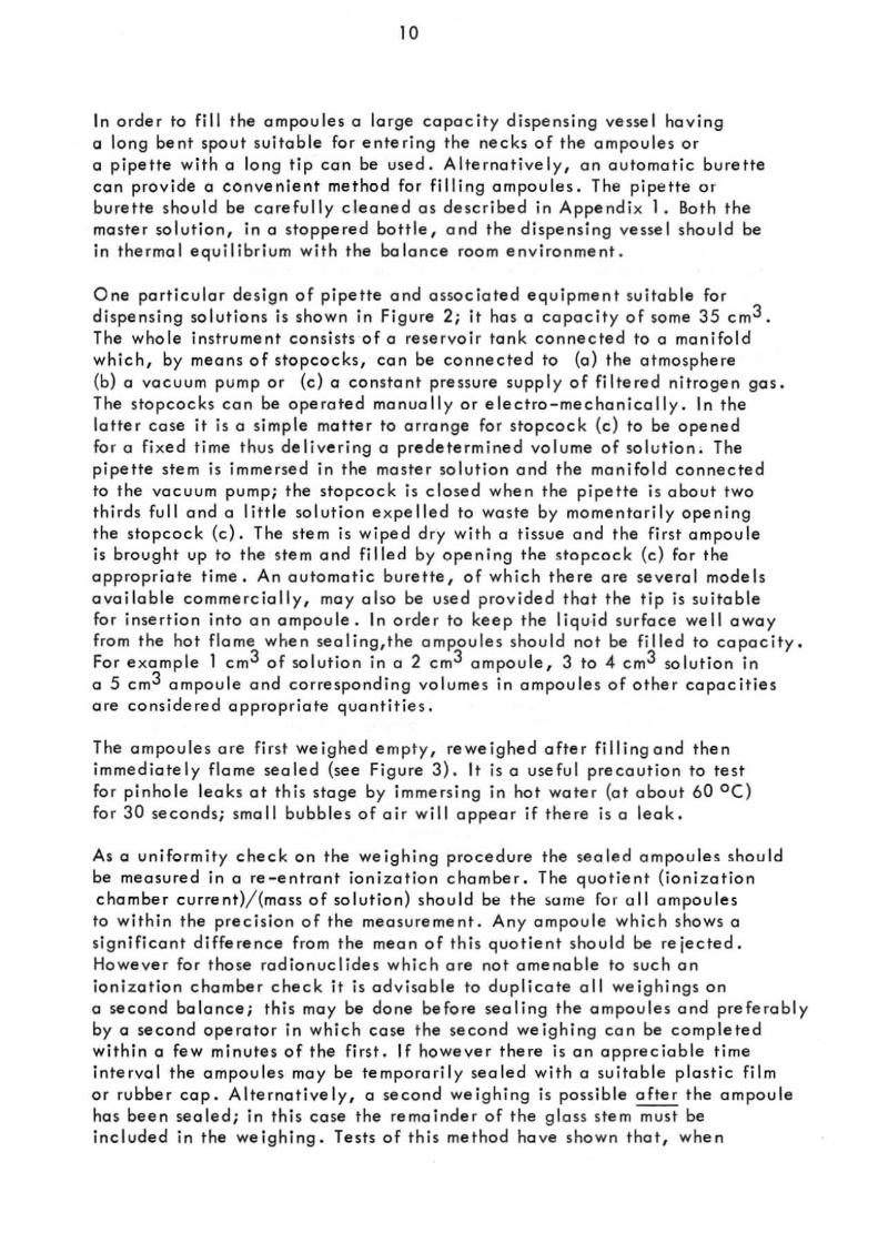
In order to fill the ampoules a large capacity dispensing vesse l having a long bent spout suitable for entering the necks of the ampoules or a pipette wit h 0 long tip can be used. Alternatively, an automatic burette can provide a convenient method for filling ampoules. The pipette or burette shou ld be care full y cleaned as described in Appendix 1. Both the ma ster solution , in a stoppered bottle, and the dispensing vesse l should be in thermal equilibrium with the balance room environment.
One particular design of pipette and associated eq uipment suitable for dispensing solutions is shown in Figure 2; it has 0 capacity of some 35 cm 3 . The who le instrument consists of 0 reservoir tank connected to 0 manifold which, by means of stopcocks, con be connected to (0) the atmosphere (b) a vacuum pump or (c) a constant pressure supp ly of filtered nitrogen gas. The stopcocks can be operated manuall y or electra-mechanically. In the latte r Case it is a simple matter to arrange for sto pcoc k (c ) to be opened for a fixed time thus delivering a predetermined volu me of solut ion ; The pipette stem is immersed in the master solutio n and the manifold connected to the va cuum pump; the stopcock is clo sed when the pipette is about two third s full and a little solution e x pelled to waste by momentarily opening the stopcock (c ). The stem is wiped dry w ith a tissue and the first ampoule is brought up to the stem and filled by openi ng the stopco ck (c) for the appropriate time. An automatic burette, of which there are several model s available commercially, may also be used provided that the tip is suitable for insertion into an ampoule. In order to keep the liquid su rface well away from the hot flame whe n sealing,the ampoules should not be filled to capacity. For e xample 1 cm 3 of solution in 02 cm 3 ampoule, 3 to 4. cm 3 so lution in 05 cm 3 ampoule ond corre sponding vo lu me s in ampoules of other capacities o re considered appropriate quantitie s.
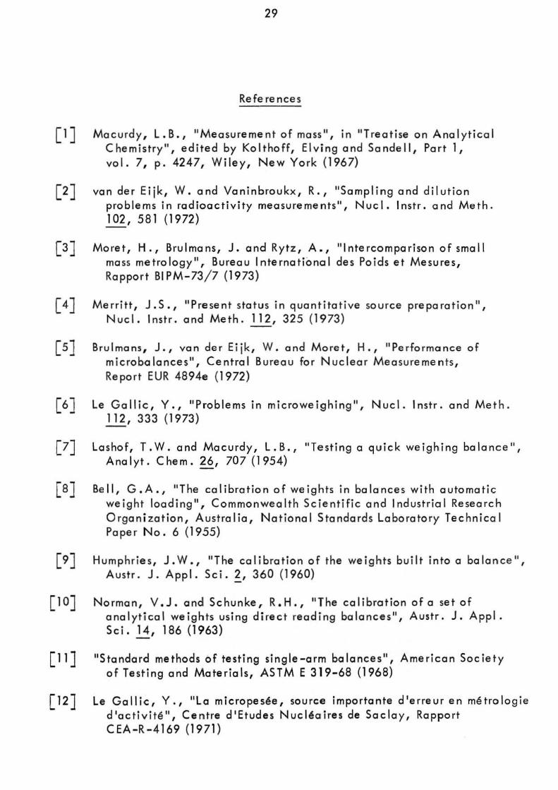
The ampoules are first we ighed empty, reweighed after filling and then immediately flame sealed (see Fi gure 3). It is a useful precaution to test for pinhole lea ks at this s tage by immersi ng in hot water (at about 60 oC) for 30 seconds; small bubbles of air will appear if there is a lea k.
As a uniformit y check on the weighing procedure the sea led ampoules should be measured in a re-entrant ionization chamber. The quotient (ionization chamber current)/ (mass of solution) should be the sa me for a ll ampoules to within the precision of the measurement . An y ampo u le which shows a significant difference from the mean of this quotient shou ld be rejected. However for those radionuclides which are not amenable to such an ionization chamber check it is advisable to duplicate all we ighings on a seco nd balance; this may be done before sealing the ampoules and preferably by a second operator in which case t he second weighing can be completed within a few minutes of the first. If however there is an appreciable time interval the ampoule s may be temporaril y sea led with a suitab le plastic film or rubber cap. Alternati ve ly , a second we ighing is possible after t he ampoule ha s been sealed; in this case the rema inder of the glass stem must be included in the weighi ng. Tests of this method hove shown that, when

11
(a) (b)N-~
+ (c) .....
t
Ballast volumt
Atmosphort Vacuum Constant pressure pump N2 suppl y
FIGURE 2
Sketch of dispensing equipment as used at the National Physical Laboratory (U .K .)

12
Figure 3
Flame-sealing apparatus (National Ph ysical Laboratory , U. K.)

13
borosilicate glass ampoules of 2 cm 3 nominal capacity and containing 1 g o·f woter ore sea led with the equipment shown in Figure 3, there is an apparent average mass loss of about 0.25 mg but that, when the ampoules are reopened, the average mass loss is reduced to less than 0.05 mg. Subsidiary experiments have shown that this phenomenon is mainl y due to the expansion and partial loss of air within the ampoule on heating, most of this lo ss being made good on reopening. Thus, it is evident that the change in radioactive concentration due to the ampoule sea ling process is negligible for all practical purposes.
As indicated above, the comparison of activities within the ampoules ma y also be corried out by means of Nal(TI) or Ge(Li} detectors. Having sealed and checked the ampoules they should then be labelled. The information on the label should include at least the rodionuclide, the oppro xi mote activity (w ith date) and a reference number. More details can be given if space permi ts, but in any case a separate statement (w hich should not be confused with the statement of the final result) 'shou ld accompany each ampoule dispatche d and give not only the above information but also the mass and chemical composition of the solution.
The evaporation rate from an unsealed glass ampoule ha s been quoted as about 0.5 mg/ h [2J to 2 mg/ h [18J but, even allowing 12 minutes for weighing, these rates represent possible fractional losses of only 0.01 to 0.04% for 1 g aliquots and correspondingl y smaller fractional lo sse s for larger aliquots. Hence the change in radioactive concentration due both to evaporation from unsealed ampoules whilst weighing and to the sealing process itself, should be negligible.
Two or three ampoules for meaSurement should be selected ot random from the batch, the remainder being available for distribution.
DETAILS OF PROCEDURES : RECEIVING LABORATORY
On receipt by a loboratory the outside of the ampoules should be checked for activity by means of a w ipe test. The contents should then be thoroughl y shaken to overcome any distillation phenomena that may have occurred in transit and the solution induced to drain completely from the ampoule tip. Simple tapping of the ampoule is usuall y sufficient to obtain thi s provided a rounded flame-sealed end, rother than a pointed tip has been achieved; centrifuging would certainly ensure proper drainage. The ampoules should then be left in the balance room in order to achieve thermal equilibrium with their environment.

14
In order to provide an independent check on tile dilution foctor os obtained by the gravimetric procedure described below, it is recommended that ionization chamber measurements be made on aliquots of both the undiluted and diluted solutions of those radionuclides which emit suitable photon radiation . If the dynamic range of the ionization chamber is adequate and the ampoules in which the solution is received are the same as those customarily used by" the laboratory for ionization chamber work, then it is possible to make measurements on the ampoules before opening them. However, the second condition is rather unlikely to be fulfilled, in which case it is necessary to transfer some of the solution to "standardl1 ampoules. These standard ampoules should, if necessary, be topped . up to a constant height in tl1e normal way by the addition of inactive solution (see Appendix 5). However, if the quantity of active solution is limited, no additional solution should be added so that the ampou les may be reopened after the ionization chamber measurements and the contents used in the preparation of the diluted solutions.
Dilution
The dilution procedure requires a stoppered glass dilution flask, a transfer pycnometer which may be glass or polyethylene, a suitable glass funnel and a further vessel containing the diluent. The dilution flask may be any suitable vessel and a variety of shapes have been used, but an Erlenmeyer or volumetric flask of about 10 to 20 cm 3 capacity can be recommended; volumetric flasks are available with plastic screw caps and teflon gaskets and provide a useful alternative to glass stoppers which may be lightly greased or used "dry" . The advantage of lightly greasing is, of course, that the solution may be stored for a long period of time with the assurance that no loss due to evaporation can take place and that it allows the flask to be repeatedly inverted for mi xing purposes; plastic screw caps are also advantageous in this respect. On the other hand the evaporation rote from a dry stoppered flask is sufficiently small that it may be used for the dilution process when sources are to be dispensed immediately. The necessity for inverting the flask to achieve complete mixing has been questioned [17, 18J. The arguments for not inverting the flask are, firstly, to avoid liquid, which is not yet mixed, being trapped in the stopper or cap crevices and, secondly, where the solution is to be assayed by liquid scintillation counting, to avoid any possible contamination of the scintillator by grease which, according to some authorities [30J, may cause quenching. However, the proponents for inverting suggest it as a safeguard for complete mixing [4J. The important point is to be aware of the possible pitfalls in whichever technique is adopted . Further it is equally important that a 11 the glassware should be clean (see Appendix 1) and in thermal equilibrium with the balance room environment. The pycnometer may readily be made from commercially available virgin polyethylene bottles*. A technique for making such
• Supplied by Canu, Equipment Ltd., 340 Glad,tone Avenue, Ottawa, Canada

15
pycnometers is described in Appendix 3. Glass pycnometers may also be used [22J; however, it is necessary to grind and flame the pycnometer tips in order to produce a smooth rounded surface and then add a woterrepellent coating (Appendix 2); they also require a detachable (via a dry cone and joint) rubber bulb or syringe to expel the solution. The polyethylene pycnometer is possibly to be preferred for diluting and dispensing sources. In general the diluent should be mode up to maintain the same inactive chemical composition and concentration as the master solution; however, if the experimenter has evidence that a lower carrier concentration is acceptable from the point of view of adsorption then the chemical composition of the diluent may be chosen so that this lo wer concentration is achieved in the diluted so lution. The diluent can be conveniently stored in a graduated flask with a dry stopper and subsequent ly transferred to the dilution flask by means of the g lass funnel. Both vessels and diluent should be in thermal equilibrium with their environment.
The dilution flask is first weighed. If 0 dry stopper is to be used then the stopper may, if desired , be weighed with the flask (but note that, when making two or more dilutions, a flask and its stopper should be clearly identified) although if a greased stopper is to be used the flask only should be weighed [4J . Opening of the ampoule containing the solution to be diluted can be accomplished by drawing a file mark near the top of the neck. The tip is then cracked by momentarily contacting the file mark with either a small bead of molten glass or a red hot wire . Immediatel y after the glass tip has been removed, the liquid shou ld be withdrawn into the pycnometer. There is usually no need to withdrC"w all of the solution and it is much more important to remove an adequate sample (a gram or more) quickly in one operation witho ut expelling air into the so lution from the pycnometer. Because the operator's hand may disturb the thermal equilibrium of the pycnometer and contents it is essential to handle pycnometers only wi th long tweezers or other remote handling equipment (Fi gure 4). The time required for transfer shou Id not toke more than a few minutes at the most. After wi thdra wing the solution the outside of the pycnometer stem is wiped wit h a tissue and, if small droplets are found to adhere to the interior, a few drops are expelled to waste. The pressure on the ampoule (in the case of a polyethylene pycnometer) or on the detachable syr inge (in the case of a glass pycnometer) is then released slowly so as to lea ve the stem free of liquid droplets. The pycnometer shou ld then be weighed, care being taken to ensu,'e that the pycnometer and contents are still in thermal equilibrium with the balance enclosure.
The pycnometer is then removed from the balance and preferably not less than several hundred milligrams of the solution are dispensed into the dilution flask in such a way that droplets are not allowed to adhere to the glass wa ll s near the neck of the flask. The pycnometer is then reweighed. Some laboratories also reweigh the (stoppered) flask ot this point. The difference in weight wi ll be s lightl y less than that indicated by the pycnometer weighings {which shou ld be used in calculating the dilution factor} owing to

16
Figure 4 - Tweezers for handling pycnometers (from reference [16J)
evaporation losses but it serves a s Cl check on gross weighing mistakes. Next, the diluent should be added to the dilution flask via the funnel ar other suitable means of transfer such as Cl pipette, care being again taken to prevent sp·lashing. The dilution flask is then reweighed together with, if appropri,ate, its stopper*. Immediately after weighing, the contents of
* At the expense of making the check on the pycnometer weighings rather less sensitive, the order in which the components are added to the dilution flask ma y be reversed but opinion is divided on this. Adding the diluent first is done in order to occupy any adsorption sites with inacti ve rather than active material, while adding the active solution to the diluent is felt by some to cause more splashing. In ane procedure part of the diluent is put into the flask first and the remainder after delivery of the active solution.

17
the dilution flask should be mixed. Care should be taken to ensure that any drops which may have adhered to the walls of the flask should not escape being mixed with the main volume. As indicated above, opinion is divided on whether or not the dilution flask should be inverted in order to mix the master solution and the diluent. The evidence to date suggests that complete mixing can be achieved by gently swirling the solution in the dilution flask [17J and in order to carry out this swirling effectively the flask should not be filled to more than half its nominal capocity.
If A is the mass of the dilution flask empty, D the mass of flask plus total solution, and Band C the pycnometer plus solution masse s before and after expelling the master solution into the flask, then the dilution factor is (D-A)/(B-C). At least one further dilution should be made from the same ampoule and the dilution factor varied by an appreciable amount, say a factor of two. In generol, dilution factors should not. e xceed 50 in an y one dilution and preferably should not be more than 30. If a larger factor is necessary it may be achieved in two or more stages. larger factors may also be achieved provided that a balance of suitable capacity is available to accommodate a larger dilution flask; hawever, it should be remembered that the greater the dilution the more difficult it becomes to achieve complete mi xi ng.
The dilution procedure itself is now complete. The remainder of the solution in the pycnometer can be stored either by delivering it to a glass ampoule which is then flame sealed or, if contained in a polyethylene pycnometer, by simply sealing the capillary in a microflame. It should be realized, however, that there is an evaporation loss through the pol yethy lene walls which may be of the order of 0.1 mg per day. Although this can be reduced by storing the ampoule in a closed container in which there is an open vessel containing an inactive solution of the same chemical composition as that within the ampoule [18J,it is recommended that, for storage over an appreciable period of time, a flame-sealed glass ampoule or greased stoppered flask be used.
Source preparation
The ne x t stage is the preparation of sources suitable for counting and, if a sensitive ionization chamber is available, also of sealed ampoules in orde r to check the dilution factor. by ionization current ratios. A series of su itable source mounts is required for 4ri proportional counting or vials for liquid scintillation counting, together with a few ampoule s. It is, of course, imperative that a different pycnometer be used for the transfer of the diluted solution from that used for the strong solution, and indeed pycnometers should be discarded after use. Again all glassware should be clean and in thermal equilibrium with the balance room environment.

18
Some solution is carefully drawn into the pycnometer without bubbling and the outside of the pycnometer stem wiped with a tissue. In one weighing technique the pycnometer is weighed using the set of balance weights and then a drop or two of the solution is dispensed on to the source mount, the pycnometer being immediately weighed again: this weighing is also the initiol weighing for the second source. Thus a series of some 7 to 10 sources can be prepared and, after counting, the mean value for the activity per unit mass of the so lution is calculated. In this way the uncertainties associated with the indi vidua l weights used for all but the first and lost weighings of the series are cancelled, i ,e. they do not contribute an y uncertainty to the mean value for the radioactive concentration. An alternative technique is substitution weighing and involves the use of the optical sca le and a reference weight approximately equal to the mass of the liquid drop dispensed. The pycnometer is first counterpoised on the balance and the reading of the optical scale noted, the internal balance weigh ts being used os tares only. A drop is then expelled on to a source moun t and the pycnometer together with the reference weight are placed on the balance pan. The new optical sca le reading which, wi th care, wi ll be close to the first, is recorded . The mass of the expelled drop is thus the algebraic difference between these two readings plus the mass of the reference weight [6J. The heavy reliance that this method puts on a single calibrated reference weight can be avoided by using a series of such weights [31]. With care both techniques can give adequate precision and accuracy; however it is not the intention of this monograph to discuss the relative merits of these two methods at this point in time particularly since the recent commercia l development of electrobalances will to some extent influence such an evaluation.
In using polyethylene pycnometers particularly, it so metime s happens that, due to capillary forces, some of the so lution rema ins in the stem after dispensing a source. Thus the air inside the pycnometer cannot come into contact with the ambient air and is at a s lightl y lower pressure. Hence, on reweighing the pycnometer, the vo lume of the dispensed drop is not rep laced by ambient air as is required for the normal buoyancy correction (see Appendix 4). This effect can be avoided by first holding the pycnometer with the ste m in an upwards direction and gently squeez ing. With the pressure still applied the pycnometer is . turned downwards and a drop dispensed on to the mount by additional squeez ing. After releasing, the pressure inside the pycnometer will reduce and allow the withdrawal of all the solution from the capillary.
For so lid sources prepared for 4rr proportional counting, source masses in the range 20 to 50 mg have been found to be acceptable and the dilution fac tor shou ld be so arranged that sources in this mass range give a suitable counting rate. If seeding or spreading agents are to be used to improve the uniformity of sources for 4rr proportional counting these may be dispensed on to the source mount before the deposition of the active so lution si nce any splashing re su lting from the first operation is then immaterial. Different radionuclides may, of course, require different source preparation techniques : a survey of source preparation procedures, which includes on extensive list of references to recent work in this area, may be found in reference [32J .

19
Fo r liq uid scintillat io n co.unting t he scint il lctor and radioacti ve solutions ma y be di spensed into the counting v iol s separately . In ma ny ca se s thi s is the preferred metho d since the alternati ve, that of pre-mi x ing the sinctillator a nd radioacti ve solutions, in vol ve s weighing solutions ha ving hi gh vapour pre ssure s, although an elegont method to overcome the problem of rapid e vaporat ion has been described [ 33J. The pre-mi x ing method doe s ho we ve r ho ve the ad vantage of weighing a considerabl y larger ma ss of rad ioacti ve solution with the consequent reduction in the fractional unce rtainty a ssociate d with this step but, because a known oliquot must be ex tracted from the bulk solution for each counting v ial, it is essential that the com~onents be tho roughl y mi xed by, for e xample, mechanical . shaking [34 J . Whil e mix ing is also de sirable in the first method it is equall y important that drops of the solution do not become lodged in the c re vices of the vial cap or stopper and hence for this method gentle swirling is reco mmended ; alternati vel y, the contents ma y be mi xed by means of a (clean) gla ss stir r ing rod. Most laboratorie s which use l iqu id scintillation c o untin g fo r t he establi shment of radioacti vity standa rds use to lue ne (o r xy lene ) fo r the main sol vent with about 10 to 20% ethanol a s an intermedia te so lvent together with PPO and POPOP as primary and secondary solute s respectivel y . In preparing and mi xi ng these solutions with the radioacti ve solution it is convenient to add the ethanol to the mixing fla sk or counting v ial first, then add 0 kno wn quantity of the radioacti ve solution from a p ycnometer and then, finall y, add the sc int i llator solution itse lf. It is necessary to es tabli sh the ma x imum quanti ty of aqueous solution that can be incorpora ted into the scintillator so lut ion and yet still maintain complete miscib i lit y . Fu rther, the conditions required to pre vent adso rpt ion from the final mi x ture on to the v ial walls sho u ld also be es·tabl ished. For toluene ba sed scintillators it is found that a relati vel y high acid concentration is required and some wo rkers add a drop of concentrated acid to the ethanol before the ad d ition of the radioacti ve aliquot and the scintillator solution. Dio xane ba sed scintillators can accommo date considerabl y weaker solutions w itho ut adsorp t ion but suffer from the fact that dio xane e x hibi ts chemilumine scence on con tact with water . Because o f the possible sensiti v ity of both vial s and solu tio ns to pho sphore scence induced by light [34,35J t he entire source preparation should be carried out in subdued red light or, alternati vel y, the filled vials should be stored for se veral da ys in the dark prior to countin g .
Fo r radionuclide s e mitting suitable photon radiation, some ampoules should be filled with the diluted solution, sealed and measured in an ionization chamber. Two or three such ampoules can be prepared either immediatel y be fore o r immediatel y afte r (or preferabl y both) the preparation of the co untin g source s . The se measurements together with simila r mea surements on ampou les prepared from the undiluted master so lution enable an independent check on the dilution factor to be obtained . Subsequentl y , these ampoules can be used, if ne cessary, for impurity checks by, for e xample, half life mea surements and y-ray spectroscopy . It is recommended that at least two ampoules of the master solution should be opened and at least two dilutions made from each, with the dilution facto rs differing by on appreciable amount.

20
Efficiency tracer measureme,nts
The efficiency tracer technique for the mea surement of pure ~-emitters requires a known amount of tracer activity to be added to the unknown pure ~ -acti vity. It is a simp le matter to prepare and calibrate a solution of the ~-y trocer activity using the diluting and dispensing procedures described above. The mix,ing of the two so lutions is best carried out ot the diluted level (i. e . at about a concentration le vel of la fJ-Ci/g). That is to say, both unknown and trocer activities are separa tel y diluted and then combined together by dispensing quantities of the order of 1 gram of each into a suitable flask and mi xing_ Counting sources may then be prepared; if, in 4rr proportional counting, seeding or spreadi ng ogents are to be used there may be, as mentioned above, some advantage in depositing these and any inactive carrier before dispensing the active so lution .
UNCERTAINTIES
The random and systematic errors associated with the manipulations described above have been discussed by several authors. It has been reported [16, 18J that the random uncertainties for repeated measurements are of the order of 0.02% and that any systematic uncertainties should be considerably less than this, provided that Hgood laboratory practice H is followed. An experimental meosurement of 233 sources prepared from 33 dilutions [17J gove stondord deviations ranging from 0.010 to 0.099%. Due to the wide ly differing measurement conditions, the 33 va lues cannot be combined rigorously. Howe ver, the arithmetic mean of 0.055% is perhaps representative of the standard deviation to be expected. Of this value about 0.05% is accounted for by counting sta tistics leaving about 0.02% due to the random uncertainty associated with diluting and source pre,Paration, - in rather good agreement wit h the estimates found in references L 16] and [18]. The former authors derived by experiment the random uncertainty associated with the weighing of 0 single drop, using their balance and dispensing technique, as about 12 I-L..g (sta ndard deviation) wh ich con be compared with an earlier estimate of 10 I-L9 for a different type of balance [22J. Another report [6J estima te s an uncertainty of 12 f.L9 for a -sing le drop measurement; however this value includes some systematic as well as random components. In this analysis of the problem, the author emphasizes the need for careful calibration of the balance weights and optical scale by means of reference weights calibrated by a mass metrology laboratory.
A recent comparison of metal masses in the range 20 to 100 mg has suggested that professional mass metrology laboratories agree to about ~ 1 fLg, while the agreement obtained in a number 0.( radionuclide laboratories using Mettler M5 balances was about.! 6 ~ when using either ca librated dial

21
weights and optical scales or calibrated reference weights [3]. Howe ver deviations of + 10 (L9 or more were observed using uncalibroted balances, that is to saY/-balances which had no calibration other than the manufacturer' s specification . Since the se uncertainties refer to the mass determination of solid samples, as opposed to liquid samples , and were obtained under ideal conditions they must be regarded as the ultimate limit that ma y be achieved by current technique. In any practical situation in radionuclide metrology the uncertainties may be considerably greater.
Effects which ma y contribute to the systematic uncertainty include the following:
1. Evaporation from open ampoules, pycnometers and dilution flasks. In a t ypical situation in which the man"ipulative procedures were assumed to take about four hours, this effect has been assessed to be about 0.004% [18] and shown e x perimentall y to be less than 0 .. 03 % [36].
2. Adherence of d roplets on the tip of pycnometers. For carefully prepared glass pycnometers this ha s been shown to be le ss than 1 fJ-g, i .•. 0.005% on a 20 mg drop [22] . Sinc. pol yethy l.ne is a hydrophobic material the adherence of droplets on pycnometers made of this material is likel y to be small although no e x periments establishing limits have been published .
3. Buo yanc y correction (see Appendi x 4). The correction for common ly used solutions and balance weights is about 0.1 % and th is va lue wou ld seldom vary by more than a few per cent.
4. Uncertainties in the balance weights and, if fitted, the optical scale of the balance. Typically, individual weights ore quoted by commercial supplie rs as better than + la f.Lg, or when taken in groups, better than + 20 j...I..og of their ~ominal va lue . However, weights may be individ-z.ally calibrated to higher accuracies and in any case it is essential to check the manufacturer' s specification. There may also be some non linearity in the response of the optical scale . A useful discussion of these points is given in the recent report on mass comparisons mentioned above [}1 and also in a report on the performance of various microbalances 15'] .
5. Uniformity of mi x ing. Any error due to this has been shown to be very small [17J.
Systematic uncertainties are thus seen to be sma ll but it must be emphasized that much larger uncertainties ma y occur if the relatively simple precautions described in this monograph are not taken.

22
CONCLUSION
The e x tensi ve e xperimental wark aimed at quantifying the possi ble uncertainty estimates described above has shown that, with reasonable precautions, the diluting and dispensing procedures should not intraduce total systematic and random uncertainties of more than 0.1 % in the final result of a radioactive concentration measurement and with care accu racies better than this may be achieved. It is possible, and indeed almost mandatory, to check the efficac y of the procedures at any laboratory by carrying out the following internal check. A solution of, for e xample, 60Co is prepared and the manipulations described in this monograph carried out. In this case several ampoules (> 5) of the master solution should be prepared, opened, diluted and sources dispensed, making t wo dilutions from each ampoule. The sources should be counted with sufficient statistical precision in a 4it~-y coincidence system. If the total spread of the results from these ten or more dilutions is less than 0.2 % the procedures are of sufficient precision to be acceptable . Such an internal check should be carried out by every laboratory before participating in an international comparison.

23
Appendix 1
CLEANING TREATMENT FOR GLASS AND POLYETHYLENE VESSELS
Whi le glass of o ne type or another is the most frequently used material for vessels and conta iners in chemical work, it is not possible to obtain o universa ll y clean gloss surface. What may be acceptable for one purpose may not be for another. A discussion of thi s together with a description of the various types of glasses, their surface properties under different conditions and detai led c leaning treatments may be found in the literature [37J . However, the follow in g three me thod s for c leaning new g lo ss or po lyethy le ne vesse ls have been found satisfactory for most work in radioactivity metrology.
Method I - The vesse ls are soaked for 24 hours in Q solution of sodium dichromate in concentrated su lphuric acid ("chro mic acid H
). They are then rinsed three time s in distilled water and once in ethanol and finally dried in an oven a t 35 °C. Rinsing should be t horough since the presence of sulphate ions can cause precipitation or colloidal effects in solutions containing cations wh ich form insoluble sulphates. Chromate ion is also st rong ly sorbed on glass [26J . It may be removed with a comp le x ing agent, e.g. by rinsing with dilute oxa li c acid followed by a distilled water rinse .
Method 11 (for g la ssware only) - The vessels or ampoules cre filled with hot carrier solut ion of the same concentration as used later for the radioactive solution. They are then dipped for two to three hours in a boiling water -bath . Thereafter they are emptied, rinsed w ith de ionized wa ter and dried in an oven at about 50 °C.
Method III - The vesse ls are immersed in a solution comprising approximately 60% (by volume) deionized water , 35% concentrated nitric acid, 3% concentrated hydrofluoric acid and 2% liquid detergent (e . g . Teepol), for 5 to 10 minutes depending on the age of the solution·. The vessels are then rinsed with de ionized water three times. In the Case of narrow necked ampoules it may be necessary to expel the wate r by blowing filtered nitrogen gas into the ampoule through a thin tube inserted down the neck. The glassware is then dried in an oven a t about 100 °c for a time depending on the size and shape of the article. For a glass pycnometer, for example, w ith a narrow orifice the time required is about three hours but is considerably less for dilution flasks. In the case of polyethylene pycnometers a lower oven temperature for a so mewhat longer time is re quired since polyeth y lene becomes soft ct 100 °C .
.. The solution should be stored in a polyethylene container.

24
Appendix 2
WATER -REPELLENT SILICONE COATINGS
If it is considered necessary glassware con be made extremely water repellent by the following techniques. Glassware must first be cleaned and dried (at < 200 °C to avoid irreversible dehydro xy lation of the surface). A number of commercial preparations are available [28,37J I usuall y a s solutions of mi xed chlorosilanes (chie fl y dimethyldichlorosilane) in a suitable so lvent such as benzene or carbon tetrachloride. On contacting the gloss surface the chlorosilanes ore hydrolysed by the reactive hydro xy groups and an y absorbed atmospheric water on the gloss surface to form a wa ter-repellent polysilo xane film. The cooting is applied by momentarily immersi ng the glassware in the silicone so lution and rinsing with benzene or carbon tetrachloride to remove the He! formed. The vessels are then left to drain. It should be noted that same silicone fluids (e.g. methylhydrogensilo xane, which forms 0 very durable surface , but, unlike dimethyldichlorosilone, requires baking for 2 to 3 hours at 140 °C) contain Si-H bond s which can act as a reducing agent.
Water - repe llent silicone coatings are necessary for glass pycnometers for w hi c h a hydrophobic surface is essential to prevent errors caused by the adherence of small droplets to the pycnometer tip [22J. In addition, siliconetreated glassware readily retains its state of cleanliness because the adhesion of many substances to g la ss is reduced. Further, so lutions stored in si li conetreated glass remain re lati ve Iy uncontaminated as lea ching from the g lass surface and dissolution of the glass itself are inhibited. Ho wever, the major ad vantage of s ilanization is that it pre vents loss of acti vity from the so lutio n to the vessel walls for mo st (but not all) radionuclides. Sili cone coated glassware ma y be useful if it is necessary to sto re high specific acti vi ty (e.g. ··carrier free ll
) solutions, although many laboratories prefer pol yethylene containers for this application. For radioacti v ity solution standards, ho wever, the carrier concentration and chemical form of the so luti on ore chosen to ensure that acti v ity losses to clean untreated glass su rfac es are negligibl e .
Some disad vantages of silanization are that the film ma y be removed to some e x tent by alkaline solutions and partiall y filled containers ma y suffer an impairment of the film at the line of the air-liquid interface after standing for some time. In addition, the procedure is time consuming and found to be unnecessary by many laboratories .
Of the clea ning procedures described in Appendi x 1, it should be noted that onl y Method I1I employing hydrofluoric acid will remo ve silicone surface films completely.

25
Appendix 3
PREPARATION OF POLYETHYLENE PYCNOMETERS
Equipment required
1. Small glass blowing torch or Bunsen burner - a hot flame is not desirable as polyethylene is quite soft at 100 °C. Neither is a wide flame desirable.
2. Forceps or tweezers.
Procedure
The plastic ampoules as received from the manufacturer have a capacity of 5 cm3 and a wall thickness of about 0.75 mm. The neck of the ampoule is drawn out in much the same way as glass tubing. The base of the ampoule is held between the thumb and first two fingers and the opening at the neck is supported with forceps. The ampoule is he Id approximate Iy horizontally over the flame and rotated slowly, heating the thick portion of the neck. Gradually most of the top 2 cm of the ampoule becomes transparent. Then the ampoule is removed from the flame and drawn out slowly to the desired length. (If it is drawn out quickly it will be pulled into two pieces). It is held taut until it regains its translucent appearance.
The capillary is allowed to harden and is then cut with the flame, sealing the end at the same time. It is good practice to apply at this stage a simple manual compression test for possible pinhole leaks. When required for use, the capillary is cut to length with a sharp blade. Typically the capillary dimensions might be 80 mm long, 0.5 mm internal diameter and 1.0 mm external diameter.

26
Appendix 4
THE BUOYANCY CORRECTION
It is we ll known that a correction for buoyancy is necessary whenever the mass of an object whose density differs from that of the balance weights is to be determined. The true mo ss, rn, is related to the apparent mass, fA- , by
where I' a is the air density, ~w is the density af the weights and r that
of the object weighed. In the case of the pycnometer technique the use of this equation is well justified si nce the evaporation rate from a well designed pycnometer is very small. Thus j' is sensibly constant and equal
a to the ambient air density. It follows that, although two apparent masses of pycnometer plus solution are recorded ond the difference taken, the I' in the abo ve equation refers only to the solution which for most purposes can be assumed to be water. Thus the correction can be made with some certainty. Ho wever this is not necessarily the case for the e x trapolation technique where the density of the air surrounding the source mount may vary os the drop evaporates.
The calibration of a set of weights is often given in terms of mosses of hypothetical weight pieces of density 8.0 g/ cm 3 whi ch would bolance the members of the set in air of density 0.0012 g/ cm3 • The calibrated set can then be regarded os a set of mosses each member of which has 0 density of 8.0 g/ cm3 . An alternative convention, common in some countries, is the 8.4/ 0 . 001 2 basi s, i.e. ma sses of assumed density 8.4 g/ cm3 weighed in air of density 0.0012 g/cm3 . Since it is unlikel y that the weights have a density of e xactly 8.0 g/cm3 (or 8.4 g/ cm 3 as the case may be) it follows that 0 further correction is necessary when weighi ng in air of density other than 0 . 0012 g/ cm3 • Thus the above equation becomes [ 38]
where (> w is the density of the weights assumed by the laboratory calibrating a
the set of weights and l'w is the true density of the weights. The lo st term t

27
in the sq ua re brackets is small, being about 1.2 x 10⁻⁵
for ~ w = 8.4 g/cm3
and P w = 7.76 g/ cm3
, as compared with the second term whi~h is a bou t
10-3 fo/aqueous samples. For measurements in air of density 9 = 0.001 2 g/cm : a
the equation becomes
The density of air in mg/ cm3
as a function of pressure, temperature and humidity is given by
Pa =
273.15 K T
-0.3783 760 mm
3 1.292 9 mg/ cm ,
where B is the barometric pressure in mm Hg, T is the absolute temperature in kelvin and p is the vapour p re ssure of wa ter in air in mm Hg. A convenien t chart for the buo yancy correction as a function of air pressu re and tem perature
has been published; the authors point out that, for ajueous samples, the error introduced by neglecting humidity is small [39 . The chart is base d on an assumed density for the balance weigh ts of 8.4 g/ cm 3 , but, as indicated above, the error introduced by using the charts in conjunction with weights of densit y 8.0 g/ cm 3 is smal l and may be neglected for most purpo ses .

28
Appendix 5
IONIZATION CHAMBER MEASUREMENTS
A review of ionization chamber tec hniques is beyond the scope of this monograph but because of the usefulness of ionization chamber measurements in checking weighings it is worth recording a few salient points. A recent survey of ionization chamber techniques ma y be found in reference [40] •
The most useful type of instrument for this purpose is a we ll-type chamber often coiled a "4J1y" ionization chamber and which is frequently operated at several atmospheres pressure in order to increa se the sensitivi t y . Typically this sensitivity may be several picoamperes per microcurie of 60Co. Strictly, for the present purpose the chamber need not be calibrated in terms of ionization current per unit activity but su ch a calibration is a very desirable feature in that a rapid assay of the activity of a sample of a given radionuclide may be made. Further, the advantages of a calibrated ionization chamber in maintainin standards of activity ha ve been stressed on many occasions [41,42 • An ionization chamber can compare ratios of activity (for the same y-ray emitting nuc lide) with a standard error of the mean of better tha n ~ 0.1%; with care a precision of! 0.02% can be achieved in favourable cases.
The ampoule wall thic kness and glass composition must be sufficiently reproducible from ampoule to ampoule so that any variation in y-ray attenuation does not add significantly to the variance of the measurements. For the same reaso n the ampoules should be filled , if necessary , by the addition of inactive solution to a canstant height. Although the use of the so -called 4Tt geometry makes source positioning less critical it is nevertheless necessary to examine the chamber for maximum response and to ensure that ampoules are positioned at this optimum point in a reproducible way. Care must be taken to ensure that the activity be kept below such le vels that the response, as a function of activity, does not depart signifi ca ntly from linearity.
The constancy of the ampoule wa ll thickness and glass composition can be tested by means of a point sou rce of low energy y-rays mounted on the end of a thin dip stick. The latter should be mounted in such a way that the source is at the centre of the ampoule to be tested; the ampoule is then positioned in a re -en tra nt ionizatio n chambe r and the ionization current noted. About 2 mei of 241Am, encapsulated at the end of a thin nickel tube, makes a convenient dip stick source. The principal electromagne ti c radiation is a y-ray of 60 keY for which the attenuation of the glass wall of the ampoule is appreciable and hence the method is rather sensitive. For a series of ampoules whose wa ll thickness is specified as being within + 0.1 mm such ionization current measurements should be constant to within "+ 0.12% (s tanda rd de v iation). This im p lies that, for 60(0 radiation, the ~ncertainty due to wall attenuation is not greater than + 0.03 %. However for some radionuclides, for example 1251, it may be de;-irable to select ampoules in ord"er to obtain even better uniformity.
29
References
Mccurd y, L.B., "Measurement of mass", in "Treatise on Anal ytical Chemistry", edited by Kolthoff, Elving and Sandell, Part 1, vol. 7, p. 4247, Wiley, New York (1967)
van der Eijk, W. and Vaninbroukx , R., IISompling and dilution problems in radioactivity measurements", Nucl. Instr. and Meth. 102,581 (1972)
Moret, H., Brulmans, J. and Rytz, A" "Intercomparison of small mass metrology", Bureau International des Poids et Mesures, Rapport BI PM-73 / 7 (1973)
Merritt, J.S., "Present status in quantitative source preparation", Nuel. Instr . and Meth. 112,325 (1973)
[5] Brulmans, J., van der Eijk, W. and Mare t, H. , I1Pe r formance of
[7J
microbolances", Central Bureau for Nuclear Mea surements, Report EUR 4894e (1972)
Le Gallic, y,/ "Problems in rnicroweighing", Nucl. Instr . and Meth . .!...!2, 333 (1973)
Lashof, T.W. and Macurdy, L.B. , "Testing a quick weighing balance", Analyt. Chem. 26, 707 (1954)
[8J Bell, G.A., "The calibration of weights in balances with automatic
[10J
[11]
[12J
weight loading", Commonwealth Scientific and Industrial Research Organization, Australia, National Standards Laboratory Technica I Poper No. 6 (1955)
Humphries, J.W., "The calibration of the weights built into a balance ", Austr. J. Appl. Sei.?, 360 (1960)
Norman, V.J. and Schunke, R.H., "The calibration ofa set of analytical weights using direct reading balances", Austr . J. Appl. Sei . .!.i, 186 (1963)
"Standard methods of testing single-arm balances", American Society of Testing and Materials, ASTM E 319-68 (1968)
Le Gallic, Y., "La micropes~e, source importante d'erreur en m~trologie d'activit~lI, Centre d'Etudes Nucleaires de Saclay, Rapport CEA-R-4169 (1971)
[14]
[15]
[16 ]
[17]
[18]
[19]
[21 ]
[22]
[23]
[24]
30
Colas, C., Ry tz, A. and Veyradier, C., "Application d'une balance Mettler du type ME22 Cl 1' ~talonnoge de radionucleides", Bureau International des Poids et Mesures, Rapport B1PM-73/ 13 (1973)
Hamilton, E., "Storage of stondard solutions in polythene bottles", Nature, Land. 193,200 (1962)
Keith, R.L.G., "Storage of standardized radioactive solutio ns", Nature, Land. 196,500 (1962)
Merritt, J.S. and Taylor, J.G. V., I'Gra vimetric samp ling in the standardization of solutions of radionuclides", Atomic Energ y of Canada Ltd., Chalk River, Report AECL-2679 (1967)
Rytz, A " Colas, C. and Veyradier, C., "Some experiments on the dilution of radioacti ve solutions and the uniformity of mixing", Bureau International des Poids et Mesures, Rapport (Jan uary 1969)
Bowes, O.C. and Boerg, A.P., "Sampling and storage of radioactive solutions", National Research Council of Canada, Ottawa, Report NRC-11513 (1 970)
Pate, B.O. and Yaffe, L., HA new material and techniques for the fabrication and measurement of very thin films for use in 4TCcounting", Can. J. Chem. 33, 15 (1955)
Lowenthal, G.C. and Smith, A.M., "Use of Au-200/0 Pd for metallising thin source supports for 4JI proportional gas flow counters", Nucl. lnstr. and Meth. 30,363 (1964)
Colas, C. and Rytz, A " "La resistance e lectriq ue des supports et des sources utilises dons le comptage 4Tl~-y", Bureau International des Poids et Mesures, Rapport BIPM-71 / 1 (1971)
Campion, P.J., Dale, J.W.G. and Wi ll iams, A., "A study of weighing techniques used in radionuc lide standardization", Nucl. lnstr. and Meth. ~, 253 (1964)
van der Eijk, W. and Moret, H., IIPrecise determination of drop weights", inllProceedings of a Symposium on Standardization of Radionuc lides", International Atomic Energy Agency, Vie nna, p. 529 (1967)
Preiss, I.L. and Fink, R.W., "Carrier-free so lution storage in glass", Nucleonics 15, 10, 108 (1957)
[25J
[26J
[27J
[28J
[30J
[31 J [32 ]
[33]
[35J
31
Le Gallic, Y", Thenard, M. and Biettmann, D., IIPrecision sur les solutions radioactives etalonnees", in "Proceedings of a Sy mposium on Standardization of Radionuclides", International Atomic Energy Agency, Vienna, p. 387 (1967)
Korenman, I.M., "Analytical chemistry of low concentrations", translated from Russian and published by Israel Program for Scientific Publications, Jerusalem (1968)
Lo we nthal, G.C. and Wyllie, H.A., liThe storage of radioactive solutions with standardized disintegration rates", Nucl . Instr . and Meth. ,!E., 367 (1973)
Smith, V. C 0, "Preparation of ultrapure water ll, in IIUltrapuritYi
methods and techniques", edited by Zief and Speights, Dekker, New York (1972)
"Usersl guides for radioacti v ity standards" (revised edition), National Academy of Sciences-National Research Council, Nuclear Science Series Monograph NAS-NS-3115, USAEC Technical Information Center (1974)
Grinber9, B., Private communication (1972)
Williams, A . , Private communication (1974)
van der Eijk, W., Oldenhof, W. and Zehner, Wo, "Preparation of thin sources, a review", Nuc!. Instr. and Meth. ,!E., 343 (1973)
Garfinkel, S.B., Mann, W.B., Medlock, R.W. and Yura, 0., "The calibration of the National Bureau of Standards! tritiatedtoluene standard of radioactivity", 1nl. J. Appl . Radiat. and Isotopes.!..£, 27 (1965)
Vaninbroukx, Ro and Spernol, A., "High precIsion 4n liquid scintillation counting", Int. J. Appl. Radiat. and Isotopes~, 289 (1965)
Scales, B., "Questions regarding the occurrence of unwanted luminescence in liquid scintillation samples", in "Liquid Scintillation Counting", Vol. 2, Heyden, London (1972)
Goodier, I. W 0 and Pritchard, DoH 0, "Evaporation losses during radioisotope standardization procedures", Int. J. Appl. Radiat. and Isotopes~, 332 (1967)

[37J
[38J
[40J
[41J
[ 42J
32
Adams, P.B., IIGlass containers for ultrapure solutions ll , in IIUltrapuritYi methods and techniques ll , edited by Zief and Speights, Dekker, New York (1972)
Colas, C. and Muller, J.W., liOn the practical evaluation of the buoyancy correction for radioactive standard sources ll , Bureau International des Poids et Mesures, Rapport BIPM-104 ( 1967)
Faure, P.K. and Gledhill, J.A., IIRapid method for applying vacuum corrections to weightsll, Anal. Chem.30, 1304 (1958)
Weiss, H.M., 114°JLy-ionization chamber measurements ll , Nucl. Instr . and Meth. 112,291 (1973)
Mann, W.B. and Seliger, H.H., IIPreparation, maintenance and application of standards of radioactivityll, National Bureau of Standards, Washington, Circular 594 (1958)
Campion, P.J. and Williams, A., IIStandards of radioactivityll, Hea I th Physics.!...!., 769 (1965)


![[Product Monograph Template - Standard]€¦ · Monographie de SURVANTA Page 1 de 38. MONOGRAPHIE. ... les propriétés du surfactant pulmonaire naturel la tension superficielle](https://img.pdfslide.us/doc/110x75/5bc3614109d3f299608c7b45/product-monograph-template-standard-monographie-de-survanta-page-1-de-38.jpg)


![40th meeting of the JCRB - BIPM - BIPM · [The corresponding BIPM presentation is available on the restricted-access JCRB working documents webpage as JCRB-40/03.1.] 3.2. BIPM QMS](https://img.pdfslide.us/doc/110x75/6047869895787e1e9f1920f7/40th-meeting-of-the-jcrb-bipm-bipm-the-corresponding-bipm-presentation-is-available.jpg)