Embed Size (px)
Citation preview

The Southern African Institute of Mining and Metallurgy Furnace Tapping Conference 2014 M. Hopf
33
Monitoring the wear of water-cooled tap-hole blocks by the OPTISAVE fibre-optic method
M. Hopf Saveway GmbH & Co. KG
Introduction
Numerous developments and improvements have been made to tap-hole designs. On the other hand, there are very specific designs in operation that have endured for many years without any modification. Nobody likes design changes because of risk – the risk of atypical wear, potential hazards, and costly repairs entailing enormous production losses.
So the philosophy ‘never touch a running system’ is maintained, because among other things there is no efficient working monitoring technology for tap-holes. In the past few years a couple of new technical solutions have been investigated and developed. Not all theoretical solutions are possible in practice. However, metallurgists are inventive, and the last word regarding efficient working tap-hole monitoring technologies has not yet been spoken.
High-intensity water-cooled copper designs
High-intensity water-cooled copper panels, tap-hole hosts, and slag tap-hole blocks entered the market more than 20 years ago. That development reduced the wear of the refractory material and refractory modules. The service life and maintenance cycles of tap-holes have improved. ‘Cooling water is the best refractory material’ according to one of the famous refractory professors.
The only disadvantage of this technology is the presence of cooling water a couple of centimetres away from the 1600°C hot metal or slag. The volume expansion for the transformation of water into steam is shown in Figure 1. It is obvious that if cooling water comes into contact with hot metal or slag at 1600°C, a volume increase between 1244 and 8534 times will result.
Figure 1. Calculated volume expansion of water
Furnace Tapping Conference 2014
34
Temperature measurement systems for tap-hole monitoring
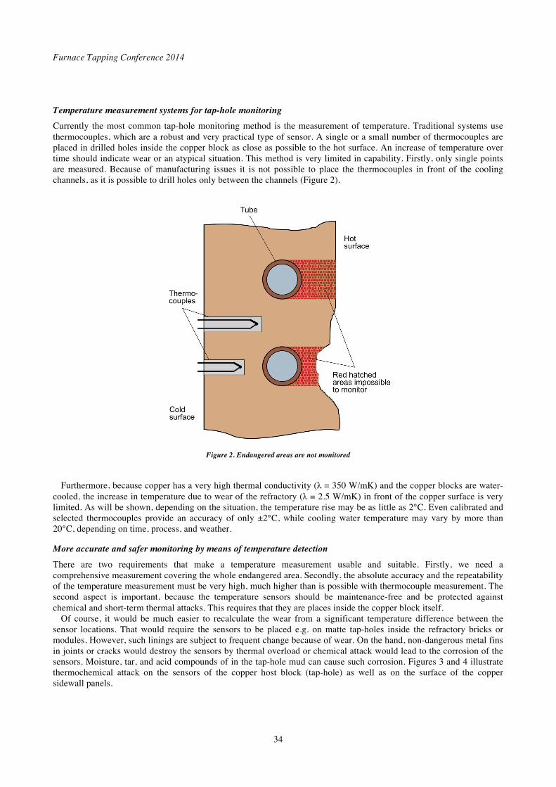
Currently the most common tap-hole monitoring method is the measurement of temperature. Traditional systems use thermocouples, which are a robust and very practical type of sensor. A single or a small number of thermocouples are placed in drilled holes inside the copper block as close as possible to the hot surface. An increase of temperature over time should indicate wear or an atypical situation. This method is very limited in capability. Firstly, only single points are measured. Because of manufacturing issues it is not possible to place the thermocouples in front of the cooling channels, as it is possible to drill holes only between the channels (Figure 2).
Figure 2. Endangered areas are not monitored
Furthermore, because copper has a very high thermal conductivity ( = 350 W/mK) and the copper blocks are water-
cooled, the increase in temperature due to wear of the refractory ( = 2.5 W/mK) in front of the copper surface is very limited. As will be shown, depending on the situation, the temperature rise may be as little as 2°C. Even calibrated and selected thermocouples provide an accuracy of only ±2°C, while cooling water temperature may vary by more than 20°C, depending on time, process, and weather.
More accurate and safer monitoring by means of temperature detection
There are two requirements that make a temperature measurement usable and suitable. Firstly, we need a comprehensive measurement covering the whole endangered area. Secondly, the absolute accuracy and the repeatability of the temperature measurement must be very high, much higher than is possible with thermocouple measurement. The second aspect is important, because the temperature sensors should be maintenance-free and be protected against chemical and short-term thermal attacks. This requires that they are places inside the copper block itself.
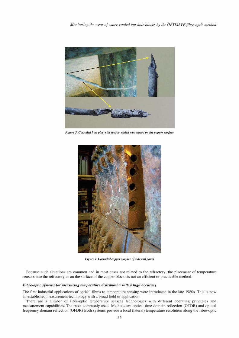
Of course, it would be much easier to recalculate the wear from a significant temperature difference between the sensor locations. That would require the sensors to be placed e.g. on matte tap-holes inside the refractory bricks or modules. However, such linings are subject to frequent change because of wear. On the hand, non-dangerous metal fins in joints or cracks would destroy the sensors by thermal overload or chemical attack would lead to the corrosion of the sensors. Moisture, tar, and acid compounds of in the tap-hole mud can cause such corrosion. Figures 3 and 4 illustrate thermochemical attack on the sensors of the copper host block (tap-hole) as well as on the surface of the copper sidewall panels.
Monitoring the wear of water-cooled tap-hole blocks by the OPTISAVE fibre-optic method
35
Figure 3. Corroded host pipe with sensor, which was placed on the copper surface
Figure 4. Corroded copper surface of sidewall panel
Because such situations are common and in most cases not related to the refractory, the placement of temperature
sensors into the refractory or on the surface of the copper blocks is not an efficient or practicable method.
Fibre-optic systems for measuring temperature distribution with a high accuracy
The first industrial applications of optical fibres to temperature sensing were introduced in the late 1980s. This is now an established measurement technology with a broad field of application.
There are a number of fibre-optic temperature sensing technologies with different operating principles and measurement capabilities. The most commonly used Methods are optical time domain reflection (OTDR) and optical frequency domain reflection (OFDR) Both systems provide a local (lateral) temperature resolution along the fibre-optic

Furnace Tapping Conference 2014
36
sensor, what is an ordinary glass fibre such as is used in the telecommunications industry. Both systems employ the Raman effect. OTDR uses the running time of a laser pulse and OFDR uses a frequency-modulated laser signal together with a Fourier transformation.
Figure 5. Basics of the Raman effect
Figure 6. Detection of local temperature distribution by OTDR
Figure 5 shows, that the wavelength of the back-scattered light is not identical with that of the input light. The
intensity of the higher wavelength (anti-Stoke band) is directly proportional to the temperature. By capturing the back- scattered light of a running laser flash in short time intervals the locality can be determined: distance = speed time (Figure 6).
Available measurement systems provide a temperature resolution and repeatability of 0.1 K and an absolute accuracy of ± 0.5 K. The spatial resolution is 250 mm with a maximum fibre length between 2 km and 10 km. In other words, the system provides a separate average temperature for each 25 cm section of a 10 km glass fibre sensor at this accuracy. Higher spatial resolutions are possible (between 3 and 10 mm) for total fibre lengths less than 100 m.
Another group of fibre-optic temperature measurement systems uses the so-called fibre Bragg grating (FBG) technology. Single sensing points (gratings) are inscribed at certain locations along the fibre length. The location of the sensing points can be chosen, but the number of measuring points is limited. According to the laws of physics, only the part of the incident light with the wavelength of the grating constant (distance G –Figure 7) will be reflected back and can be analysed by a spectrometer. If the temperature of the sensing point increases the grating constant of that point

Monitoring the wear of water-cooled tap-hole blocks by the OPTISAVE fibre-optic method
37
increases due to the thermal expansion of the glass fibre, thus the wavelength of the reflected light increases. Figures 7 and 8 explain the working principle.
Figure 7. Basic design of a Bragg grating
Figure 8. Basic working principle of the FBG measuring system
The FGB method enables very accurate temperature measurement. Common devices allow temperature resolutions of
0.05 K with an absolute accuracy of 0.2 K. The maximum number of sensing points per fibre (measurement channel) is typically 20.

Furnace Tapping Conference 2014
38
Fibre-optic sensing technologies are still developing, and more accurate measurements with higher spatial resolution can be expected in the future.
Embedding technology – requirement for practicability and cost efficiency
It can be seen that there are very sensitive measurement technologies are available that allow exhaustive monitoring of large areas. Now the question arises, how can we place such sensors inside the water-cooled blocks or copper panels? As shown previously, placement outside of the copper block leads to early destruction of the sensor. Even the surface of the copper blocks is commonly attacked by corrosion.
To circumvent this problem, the so-called ’embedding ’technology’ was developed by Saveway together with Thos Begbie in Middelburg. This technology enables the sensors to be placed inside the copper casting at the required positions. Endangered sections such as the cooling channels can be safely and exhaustively monitored. Placing the sensors in the copper addresses two main issues. Firstly, the sensors are protected against corrosion and non-dangerous, solidified metal fins. Secondly, no additional time and effort is necessary for sensor installation after the build-up or rebuild of the smelter. Furthermore, the sensors can be changed or replaced without destruction of the copper blocks or panels by placing a piping system. Figure 9 shows the principle of the embedding technology. Typically a monel tubing system is pre-manufactured and placed in a sand mould. The copper is then cast around the monel tubes. After solidification of the copper, the cooling channels are in place without any need for drilling or machining.
Figure 9. Structure of pre-manufactured cooling channel system with hosting pipe
In addition to the monel tubing system a host pipe system for the fibre-optic sensors is cast in. The monel tubes have
an inner diameter of less than 4 mm. The small host tubes are arranged in any required position between the cooling channels and the hot surface of the copper block or copper panel. Typically the host pipes follow the structure of the cooling water pipes. This enabling safe monitoring of those endangered areas. Figure 10 shows both piping systems before the casting procedure.

Monitoring the wear of water-cooled tap-hole blocks by the OPTISAVE fibre-optic method
39
Figure 10. The host pipe follows the cooling channel pipes
Modelling of a matte tap-hole block
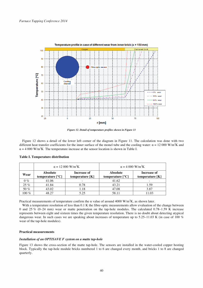
Is there a detectable change of temperature at the sensor location inside the copper in case of the refractory inlays? To answer that question, a theoretical calculation of the temperature distribution by the finite element method (FEM) was carried out.
Figure 11 shows the temperature distribution at the sensor location for four different wear situations – 0%, 25%, 50%, and 100 % wear – on the inner module brick. It can be clearly seen that the major temperature decrease takes place in the refractory lining, because the thermal conductivity is more than 100 times less than that of the copper.
Figure 11. Temperature profiles in case of refractory wear
Furnace Tapping Conference 2014
40
Figure 12. Detail of temperature profiles shown in Figure 11
Figure 12 shows a detail of the lower left corner of the diagram in Figure 11. The calculation was done with two
different heat transfer coefficients for the inner surface of the monel tube and the cooling water: = 12 000 W/m2K and = 4 000 W/m2K The temperature increase at the sensor location is shown in Table I.
Table I. Temperature distribution
= 12 000 W/m2K = 4 000 W/m2K
Wear Absolute
temperature [°C] Increase of
temperature [K] Absolute
temperature [°C] Increase of
temperature [K] 0 % 41.06 - 41.62 -
25 % 41.84 0.78 43.21 1.59 50 % 43.02 1.18 47.08 3.87
100 % 48.27 5.25 58.11 11.03
Practical measurements of temperature confirm the value of around 4000 W/m2K, as shown later. With a temperature resolution of less than 0.1 K the fibre-optic measurements allow evaluation of the change between
0 and 25 % (0–24 mm) wear or matte penetration on the tap-hole modules. The calculated 0.78–1.59 K increase represents between eight and sixteen times the given temperature resolution. There is no doubt about detecting atypical dangerous wear. In such cases we are speaking about increases of temperature up to 5.25–11.03 K (in case of 100 % wear of the tap-hole modules).
Practical measurements
Installation of an OPTISAVE F system on a matte tap-hole
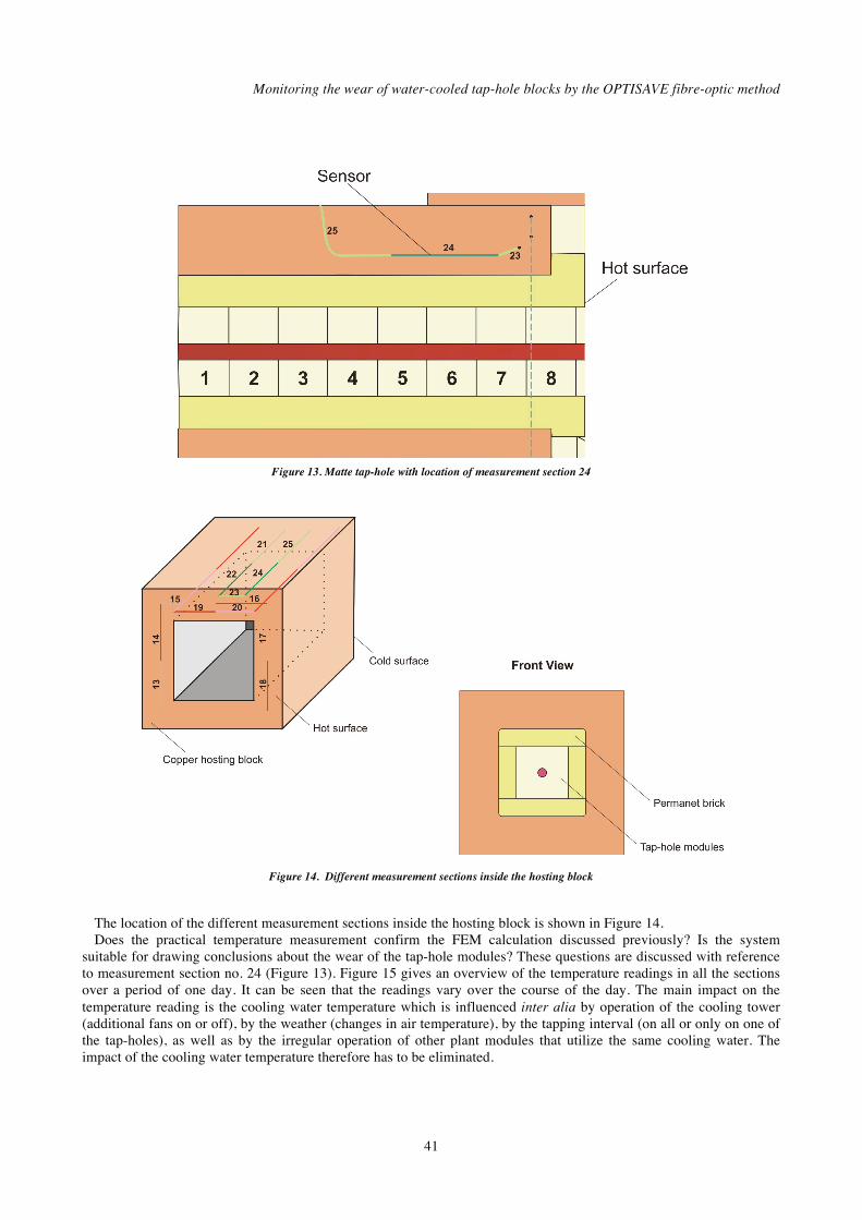
Figure 13 shows the cross-section of the matte tap-hole. The sensors are installed in the water-cooled copper hosting block. Typically the tap-hole module bricks numbered 1 to 6 are changed every month, and bricks 1 to 8 are changed quarterly.
Monitoring the wear of water-cooled tap-hole blocks by the OPTISAVE fibre-optic method
41
Figure 13. Matte tap-hole with location of measurement section 24
Figure 14. Different measurement sections inside the hosting block
The location of the different measurement sections inside the hosting block is shown in Figure 14. Does the practical temperature measurement confirm the FEM calculation discussed previously? Is the system
suitable for drawing conclusions about the wear of the tap-hole modules? These questions are discussed with reference to measurement section no. 24 (Figure 13). Figure 15 gives an overview of the temperature readings in all the sections over a period of one day. It can be seen that the readings vary over the course of the day. The main impact on the temperature reading is the cooling water temperature which is influenced inter alia by operation of the cooling tower (additional fans on or off), by the weather (changes in air temperature), by the tapping interval (on all or only on one of the tap-holes), as well as by the irregular operation of other plant modules that utilize the same cooling water. The impact of the cooling water temperature therefore has to be eliminated.
Furnace Tapping Conference 2014
42
Figure 15. Recorded temperatures over one day
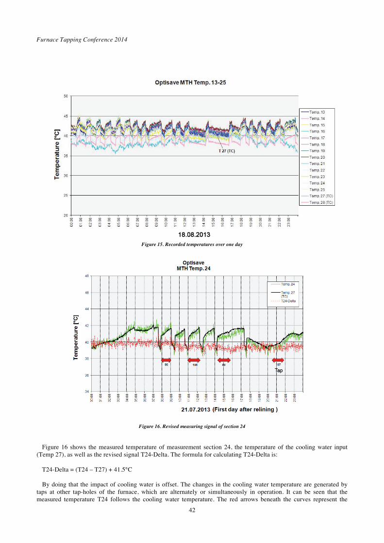
Figure 16. Revised measuring signal of section 24
Figure 16 shows the measured temperature of measurement section 24, the temperature of the cooling water input
(Temp 27), as well as the revised signal T24-Delta. The formula for calculating T24-Delta is: T24-Delta = (T24 – T27) + 41.5°C By doing that the impact of cooling water is offset. The changes in the cooling water temperature are generated by
taps at other tap-holes of the furnace, which are alternately or simultaneously in operation. It can be seen that the measured temperature T24 follows the cooling water temperature. The red arrows beneath the curves represent the
Monitoring the wear of water-cooled tap-hole blocks by the OPTISAVE fibre-optic method
43
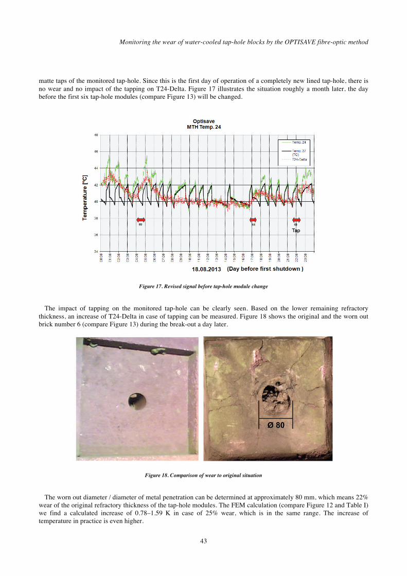
matte taps of the monitored tap-hole. Since this is the first day of operation of a completely new lined tap-hole, there is no wear and no impact of the tapping on T24-Delta. Figure 17 illustrates the situation roughly a month later, the day before the first six tap-hole modules (compare Figure 13) will be changed.
Figure 17. Revised signal before tap-hole module change
The impact of tapping on the monitored tap-hole can be clearly seen. Based on the lower remaining refractory
thickness, an increase of T24-Delta in case of tapping can be measured. Figure 18 shows the original and the worn out brick number 6 (compare Figure 13) during the break-out a day later.
Figure 18. Comparison of wear to original situation
The worn out diameter / diameter of metal penetration can be determined at approximately 80 mm, which means 22%
wear of the original refractory thickness of the tap-hole modules. The FEM calculation (compare Figure 12 and Table I) we find a calculated increase of 0.78–1.59 K in case of 25% wear, which is in the same range. The increase of temperature in practice is even higher.

Furnace Tapping Conference 2014
44
Figure 19. Confirmation and repeatability
Figure 19 shows the data for day before the second shutdown roughly a month later. The impact of tapping can be
seen clearly. The increase of temperature in case of tapping is approximately 3 K at the end of the second campaign. The wear situation was the same as that found after the first campaign.
Suitability of the embedding technology on the matte tap-hole
Currently, all the sensors are still in function (8 months’ operation). The measuring system provides plausible data. It is confirmed in practice that the system can be used to determine the wear situation on the refractory inlays of the tap-hole. It should be pointed out that 20 mm wear and / or penetration leads to a safe, detectable, and repeatable measurement signal. As shown in the calculation, in case of more severe wear the temperature will progressively increase. Therefore a critical situation will be safely and clearly identified.
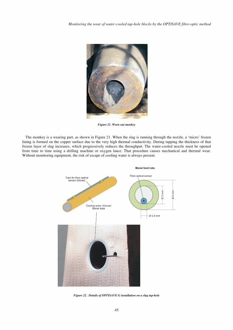
Installation of OPTISAVE G on a slag tap-hole
From 2010 the fibre-optical technology was used to monitor a slag tap-hole. A practicable way method was realized by using the embedding technology. The difference between the matte tap-hole and the slag tap-hole is that the slag tap-hole does not have a refractory inlay or lining, and consists of simply a water-cooled copper nozzle or ‘monkey’. Figure 20 shows the basic design of such a slag tap-hole. The system was installed in the monkey.
Figure 20. Slag tap-hole design
Monitoring the wear of water-cooled tap-hole blocks by the OPTISAVE fibre-optic method
45
Figure 21. Worn out monkey
The monkey is a wearing part, as shown in Figure 21. When the slag is running through the nozzle, a ‘micro’ frozen
lining is formed on the copper surface due to the very high thermal conductivity. During tapping the thickness of that frozen layer of slag increases, which progressively reduces the throughput. The water-cooled nozzle must be opened from time to time using a drilling machine or oxygen lance. That procedure causes mechanical and thermal wear. Without monitoring equipment, the risk of escape of cooling water is always present.
Figure 22. Details of OPTISAVE G installation on a slag tap-hole
Furnace Tapping Conference 2014
46
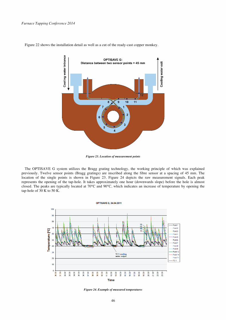
Figure 22 shows the installation detail as well as a cut of the ready-cast copper monkey.
Figure 23. Location of measurement points
The OPTISAVE G system utilizes the Bragg grating technology, the working principle of which was explained
previously. Twelve sensor points (Bragg gratings) are inscribed along the fibre sensor at a spacing of 45 mm. The location of the single points is shown in Figure 23. Figure 24 depicts the raw measurement signals. Each peak represents the opening of the tap-hole. It takes approximately one hour (downwards slope) before the hole is almost closed. The peaks are typically located at 70°C and 90°C, which indicates an increase of temperature by opening the tap-hole of 30 K to 50 K.
Figure 24. Example of measured temperatures
Monitoring the wear of water-cooled tap-hole blocks by the OPTISAVE fibre-optic method
47
Like the measurements on the matte tap-hole, the raw measurement signal must be assessed. Cooling water offset and incorporating the gradient and average increase of the signal as well as critical absolute values ensure that the measurement system provides the required output.
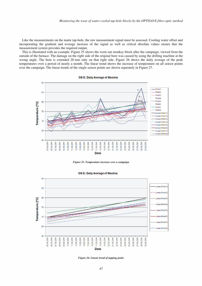
This is illustrated with an example. Figure 25 shows the worn out monkey block after the campaign, viewed from the outside of the furnace. The damage on the right side of the original bore was caused by using the drilling machine at the wrong angle. The bore is extended 20 mm only on that right side. Figure 26 shows the daily average of the peak temperatures over a period of nearly a month. The linear trend shows the increase of temperature on all sensor points over the campaign. The linear trends of the single sensor points are shown separately in Figure 27.
Figure 25. Temperature increase over a campaign
Figure 26. Linear trend of tapping peaks
Furnace Tapping Conference 2014
48
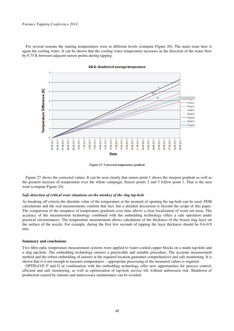
For several reasons the starting temperatures were at different levels (compare Figure 26). The main issue here is again the cooling water. It can be shown that the cooling water temperature increases in the direction of the water flow by 0.75 K between adjacent sensor points during tapping.
Figure 27. Corrected temperature gradient
Figure 27 shows the corrected values. It can be seen clearly that sensor point 1 shows the steepest gradient as well as
the greatest increase of temperature over the whole campaign. Sensor points 2 and 3 follow point 1. That is the area wear (compare Figure 24).
Safe detection of critical wear situations on the monkey of the slag tap-hole
As breaking off criteria the absolute value of the temperature at the moment of opening the tap-hole can be used. FEM calculations and the real measurements confirm that fact, but a detailed discussion is beyond the scope of this paper. The comparison of the steepness of temperature gradients over time allows a clear localization of worn out areas. The accuracy of the measurement technology combined with the embedding technology offers a safe operation under practical circumstances. The temperature measurement allows calculation of the thickness of the frozen slag layer on the surface of the nozzle. For example, during the first few seconds of tapping the layer thickness should be 0.6–0.9 mm.
Summary and conclusions
Two fibre-optic temperature measurement systems were applied to water-cooled copper blocks on a matte tap-hole and a slag tap-hole. The embedding technology ensures a practicable and suitable procedure. The accurate measurement method and the robust embedding of sensors at the required location guarantee comprehensive and safe monitoring. It is shown that it is not enough to measure temperatures – appropriate processing of the measured values is required.
OPTISAVE F and G in combination with the embedding technology offer new opportunities for process control, efficient and safe monitoring, as well as optimization of tap-hole service life without unforeseen risk. Shutdown of production caused by runouts and unnecessary maintenance can be avoided.
Monitoring the wear of water-cooled tap-hole blocks by the OPTISAVE fibre-optic method
49
References
Hoffmann, L., Müller, M. S., Krämer, S., Giebel, M., Schwotzer, G. and Wieduwilt, T. 2007. Applications of fibre optic
temperature measurement. Proceedings of the Estonian Academy of Sciences and Engineering, vol. 56, no. 4. pp.
363–378.
Hopf, M. and Rossouw, E.K.. 2006. Wandpaneel für Schmelzöfen [Wall panel for furnaces]. Patent application DE 10
2005 013 924 A1. 5 October 2006. Saveway GmbH & Co. KG and Thos Begbie & Co. (Pty) Ltd
Gerritsen, T., Shadlyn, P., Macrosty, R., Zhang, J., and Van Beek, B. . 2009. Tapblock fibre optic temperature system.
COM2009. Proceedings of the 48th Conference of Metallurgists, Sudbury, Ontario, Canada, 23–26 August 2009.
The Author
Dr.-Ing. Manfred Hopf, President, Saveway GmbH & Co. KG • School and professional education to skilled worker in machining • 1978 to 1981 military service, corporal at air force engineering • 1981 to 1986 study at Technical University Ilmenau, electrotechnics, diploma 1986 • 1986 to 1991 scientific employee at the University at the institute of electrothermicprocesses • 1990 doctors degree / Ph.D Electrical Engineering • 1992 to present President of Saveway GmbH & Co. KG, worldwide acting company
Development, manufacturing and installation of diagnostic systems for lining wear on melting and holding equipment in foundries, steel plant and primarily industry
• Inventions: six bending patents

Furnace Tapping Conference 2014
50