Embed Size (px)
Citation preview

© 2016 WILEY-VCH Verlag GmbH & Co. KGaA, Weinheim 1wileyonlinelibrary.com
Rev
iew
Monitoring of Vital Signs with Flexible and Wearable Medical Devices
Yasser Khan, Aminy E. Ostfeld, Claire M. Lochner, Adrien Pierre, and Ana C. Arias*
Y. Khan, A. E. Ostfeld, C. M. Lochner, A. Pierre, Prof. A. C. AriasDepartment of Electrical Engineering and Computer SciencesUniversity of CaliforniaBerkeley, CA 94720, USAE-mail: [email protected]
DOI: 10.1002/adma.201504366
1. Introduction
In recent years, there has been an increased demand for wear-able devices, as demonstrated by the growth of the wearable fitness market to $5 billion in 2015, which is higher by 25% from 2014—this growth rate is expected to be sustained over the next 5 years.[1] Concurrently, there has been a significantly increased interest in monitoring stress and human perfor-mance during physically demanding tasks. Wearable medical devices, for improved in-home care, customized for patients with known health issues that can benefit from regular and even continuous monitoring, are desired. Currently, devices are being developed to monitor human vital signs continuously, as noninvasively and comfortably as possible. Regular monitoring of vital signs would help to establish an individual health base-line and alert users and medical professionals of abnormalities
Advances in wireless technologies, low-power electronics, the internet of things, and in the domain of connected health are driving innovations in wearable medical devices at a tremendous pace. Wearable sensor systems composed of flexible and stretchable materials have the potential to better interface to the human skin, whereas silicon-based electronics are extremely efficient in sensor data processing and transmission. Therefore, flexible and stretchable sensors combined with low-power silicon-based electronics are a viable and efficient approach for medical monitoring. Flexible medical devices designed for monitoring human vital signs, such as body temperature, heart rate, respiration rate, blood pressure, pulse oxygenation, and blood glucose have applications in both fitness monitoring and medical diagnostics. As a review of the latest development in flexible and wearable human vitals sen-sors, the essential components required for vitals sensors are outlined and discussed here, including the reported sensor systems, sensing mechanisms, sensor fabrication, power, and data processing requirements.
indicating that further medical attention and care may be necessary. Today, most of the wearable devices have a watch format and track activity levels. By incorporating vital signs sensors, these devices can be upgraded for both fitness monitoring and medical diagnostics.
Moving toward health monitoring devices that interface well with the skin and the body may help with the adop-tion of wearable medical devices and even improve the performance of fit-ness monitoring. Considerable efforts are taking place where new fabrication techniques and materials are being applied to sensors and electronics with the goal of demonstrating flexible and conformal electronic devices. The bulky and rigid nature of conventional silicon-based devices can impede their applications in epidermal and implant-
able medical sensing.[2,3] Alternative materials, such as plastic and elastomeric substrates, used in these flexible devices are conformal by nature, lightweight, and therefore offer better interface with the human skin and soft tissue. Many sensors also use electronic and optoelectronic materials that are flex-ible by nature[4–7] while other approaches look into transferring small and thin conventional devices onto flexible substrates.[8,9] Meanwhile, silicon-based electronics provide unparalleled performance in data processing and performance. Therefore, the ideal design for a comfortable wearable medical device would take a hybrid approach where new advanced flexible materials are used in the same fabrication platform as silicon integrated circuits (ICs). Such a hybrid approach can also take into consideration the diversity of shapes and sizes of the population, making medical devices better customized for individuals. Additionally, flexibility and a good fit to the body can also improve signal quality and reduce noise from the measurement.[6,7]
Medical devices are designed to diagnose, prevent, and treat disease. According to the Food and Drug Administra-tion (FDA), a medical device should not achieve its purposes through chemical action within or on the body, and an agent which achieves its purpose through chemical action is termed as a drug.[10] Therefore, sensors ranging from a simple temper-ature sensor to an invasive electrocorticography (ECOG) sensor fall under the broader umbrella of medical devices. In this
Adv. Mater. 2016, DOI: 10.1002/adma.201504366
www.advmat.dewww.MaterialsViews.com

2 wileyonlinelibrary.com © 2016 WILEY-VCH Verlag GmbH & Co. KGaA, Weinheim
Rev
iew Yasser Khan is a Ph.D.
student in the department of Electrical Engineering and Computer Sciences at the University of California, Berkeley, in Prof. Ana Claudia Arias’ Group. He received his B.S. in Electrical Engineering from the University of Texas at Dallas in 2010, and M.S. in Electrical Engineering from King Abdullah University of
Science and Technology in 2012. Yasser’s research focuses mainly on wearable medical devices, with an emphasis on flexible bioelectronic and biophotonic sensors.
review paper, we limited our focus to noninvasive and wearable vital signs sensors. Vital signs are measurements of the body’s most basic functions and are useful in assessing the physical state of a person.
Here, we review several sensors that are flexible and could be used as wearable devices to monitor vital signs such as heart and respiration rate, temperature, blood pressure, pulse oxygenation, and blood glucose. An overview of the general working principle of each sensor is given together with examples of flexible sensors previously reported in the literature. General fabrication processes that allow flexibility are also reviewed together with schemes for data processing, transmission, and visualization. In Figure 1, a visual sum-mary of this paper is given. In Section 2, flexible health monitoring devices are described. For each sensor, the under-lying sensing principle, alternative sensing schemes, and the reported sensors in the literature are discussed. In Section 3, fabrication processes are reviewed. Section 4 describes the data processing and transmission requirements of the sen-sors, and also lists the measurement range and signal frequencies associated with different types of vital sign meas-urements. Finally, in Section 5, the power requirements of wearable electronics are discussed along with practical con-siderations such as choice of power source and storage in different sensing scenarios. Overall, in this review paper, we present all the major components in wearable biosensor sys-tems and discuss the progress made in this field, as well as the challenges that lie ahead.
2. Flexible Health Monitoring Devices
The four main vital signs routinely monitored by medical professionals are: i) body temperature, ii) heart rate, iii) res-piration rate, and iv) blood pressure;[11] v) pulse oxygenation (oxygenation of fresh arterial blood), and vi) blood glucose do not fall into the category of vital signs, yet these are widely used by medical professionals. Figure 2 gives an overview of the biosignals and sensing locations. In Figure 2a, biosignals are grouped according to the sensing location. For example, blood pressure measurements and bioelectronic measure-ments such as surface electromyography (SEMG) can be performed on the arm,[12,13] therefore these two biosignals are grouped under the red dot (Arm). Similarly, tempera-ture, heart rate, pulse oxygenation, bioelectronic, and motion signals can be obtained from the wrist, therefore these are grouped under the green dot (wrist). Other biosignals that can be extracted from the chest (orange dot), leg (yellow dot), and bodily fluids (black dot) are also shown in the figure. In Figure 2b, biosignals are listed according to precedence. The same order is followed in the paper, where we discuss the biosignal, the sensing mechanisms, and the reported flex-ible and wearable biosensors in literature used for measuring the specific biosignal. Bioelectronic and motion signals are also shown in Figure 2 because they can be used to extract important physiological information such as the stress level or movement of a person. However, considering the scope of the review paper, these two biosignals were omitted from the discussions.
2.1. Temperature
Body temperature provides an insight into the physiological state of a person. An elevated body temperature is an indi-cation of infection or fever. On the other hand, a degraded body temperature signifies low blood flow due to circulatory shock. Therefore, body temperature is regarded as the first vital sign. While measuring body temperature, the effect
Ana Claudia Arias is an Associate Professor at the Electrical Engineering and Computer Sciences Department and a faculty director of the Berkeley Wireless Research Center (BWRC) and the Swarm Lab at the University of California in Berkeley. She received her Ph.D. on semiconducting poly mer blends for photo-
voltaic devices from the Physics Department at the University of Cambridge, UK. Prior to that, she received her master and bachelor degrees in Physics from the Federal University of Paraná in Curitiba, Brazil. Her research focuses on devices based on solution processed materials and applications development for flexible sensors and electronic systems.
Aminy Erin Ostfeld gradu-ated from Brown University in 2011 with a B.S. in electrical engineering. She is currently a Ph.D. candidate in electrical engineering at the University of California, Berkeley, in the group of Prof. Ana Claudia Arias. Her research is on power systems for flexible and wearable electronics, with a special focus on photovoltaics.
Adv. Mater. 2016, DOI: 10.1002/adma.201504366
www.advmat.dewww.MaterialsViews.com
3wileyonlinelibrary.com© 2016 WILEY-VCH Verlag GmbH & Co. KGaA, Weinheim
Rev
iew
of the measurement site needs to be taken into account because body temperature varies depending on the measure-ment site; for example, at room temperature (25 °C), normal wrist temperature is around 32 °C while the body-core tem-perature is around 37 °C.[14] In wearable form factor, tem-perature sensors are usually placed on the arm or the chest, hence, recorded temperatures are less than the body-core temperature.
Body temperature can be measured using thermistors,[15–18] thermoelectric effects,[19] or via optical means.[20] However, the prominent method used in wearable sensors is the thermistor configuration. The resistance of thermistors varies according to the temperature. If the resistance increases with temperature increase, the sensor is positive temperature coefficient (PTC) type. Conversely, if the resistance decreases with temperature
increase, the sensor is negative temperature coefficient (NTC) type. The general equation governing a thermistor is given below:
β= −
exp1 1
00
R RT T
t
(1)
Here, Rt is the resistance at temperature T, R0 is the resistance at T0 (reference temperature), and β is the material constant for the thermistor. Equation (1) can be rewritten as:
β= + −
ln ln1 1
00
R RT T
t
(2)
Now, a linear relationship between ln (Rt) and 1/T is estab-lished. β represents the slope of the ln(Rt) versus 1/T plot,
Adv. Mater. 2016, DOI: 10.1002/adma.201504366
www.advmat.dewww.MaterialsViews.com
Figure 1. System flow of biosensors and a graphical overview of this review. Section 2 presents various biosensors designed to acquire biosignals. Section 3 discusses the fabrication processes reported in the literature for developing flexible medical devices. Section 4 introduces the process flow for biosignal acquisition, filtering, amplification, processing, and transmission to a host computer or portable device. Section 5 discusses the power requirements and methods of powering wearable biosensor systems.
Figure 2. Biosignals and sensing locations. a) Sensing locations for wearable medical devices. Here the biosignals are grouped according to the sensing location. Blood pressure measurements and bioelectronic measurements such as surface electromyography (SEMG) can be performed on the arm, therefore these two biosignals are grouped under the red dot (Arm). The wrist (green dot) can be used for obtaining a vast amount of biosignals—temperature, heart rate, pulse oxygenation, bioelectronic, and motion signals. Similar to the wrist, the chest (orange dot) is also a suitable biosensing location. Temperature, heart rate, and respiration rate can be extracted from the chest. The leg (yellow dot) can provide bioelectronic and motion signals. Electrochemical sensing can be performed on bodily fluids such as sweat and tear (black dot). Since bodily fluids can be obtained from dif-ferent parts of the body, the sensing location is not marked. Additionally, these biosignals can be obtained from other sensing locations, for example, pulse oxygenation can be obtained from the fresh arterial blood of the finger, earlobe, or forehead. Here, we highlighted the sensing locations where the measurements can be done in a less obtrusive manner. b) Biosignals and their corresponding sections in this review article.
4 wileyonlinelibrary.com © 2016 WILEY-VCH Verlag GmbH & Co. KGaA, Weinheim
Rev
iew
which is related to the Boltzmann relation
E
kT, where E is the
bandgap of the thermistor material and k is the Boltzmann’s constant. Generally, the sensitivity of the thermistor is quanti-fied using β and the temperature coefficient of the thermistor, α, which can be found by differentiating Equation (1) with respect to T and dividing by Rt:
α β= = − −1(% K )2
1
R
dR
dT Tt
t
(3)
Both β and α can be used to characterize the performance of the thermistor; β has the units of Kelvin, while α represents the percentage change of resistance per degree Kelvin. The described working principle and performance quantification apply to most of the reported wearable thermistors. Depending on the thermistor material, β and α can vary significantly. Some of the reported thermistors in flexible and wearable form factor and their performance parameters are listed in Table 1. For these reports, the thermistor material is deposited and pat-terned on top of conductive electrodes.
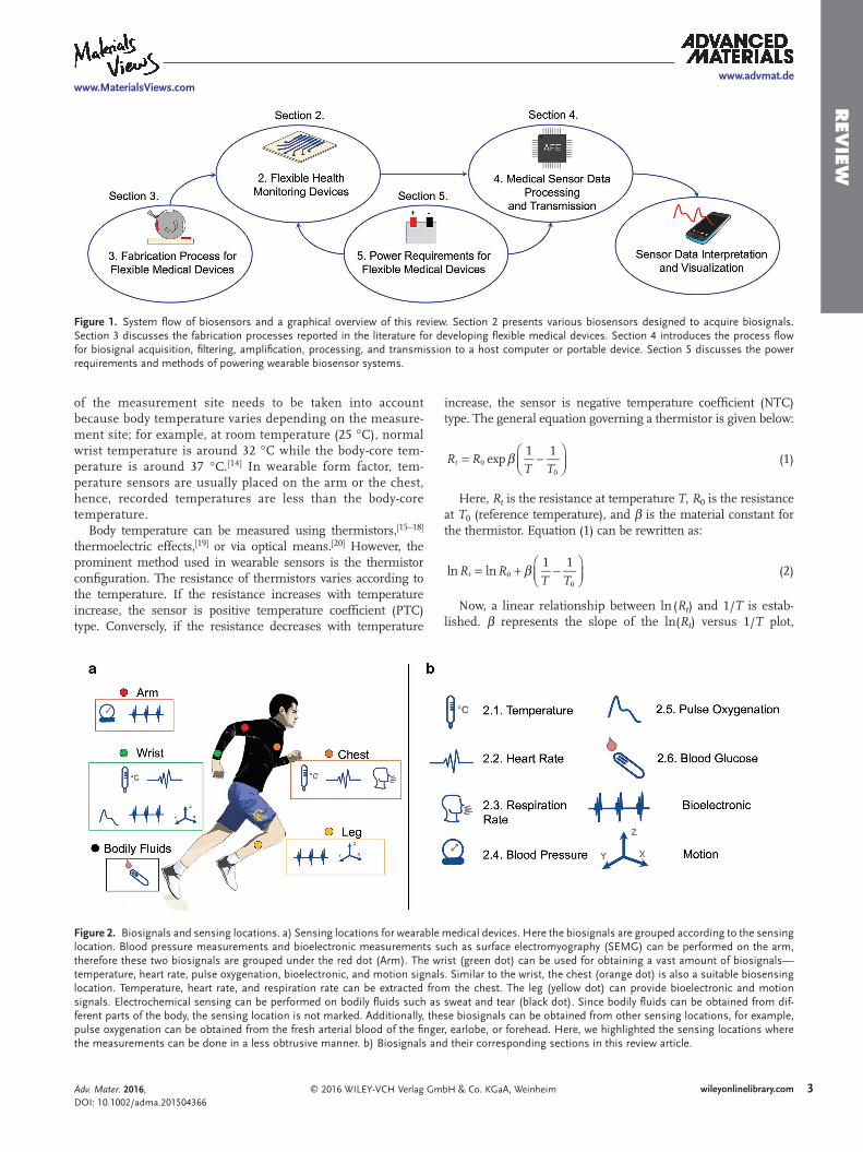
Yan et al. used resistive graphene as the temperature sensing channels and highly conductive silver nanowires (AgNWs) as electrodes (shown in Figure 3).[17] Fabricated stretchable devices proved mechanically robust and demonstrated strain dependent resistance (Figure 3b,c,e). The thermistors demon-strated β = 835.72 K and α = −1.12% K−1. Huang et al. used nickel oxide based thermistors, and demonstrated β = 4262.70 K and α = −5.71% K−1. These performance parameters are com-parable to commercially available thermistors.[18] Jeon et al. used nickel microparticle-filled binary polymer composites as the temperature sensor, where the polymers had a melting point in the range of 35 to 40 °C.[21] When the material temper-ature reaches the melting point of the polymers, the particle–particle distance of the host nickel microparticles increases due to volume expansion of the polymers, which increases the ther-mistor resistance. This results in a huge β in the sensing tem-perature zone, hence, a low gain read circuit is used to read out the sensor data. While promising advances have been made in wearable temperature sensing, a few impediments still hinder accurate temperature measurements. Most reported thermis-tors show a strain dependence,[17,18] which is not ideal for wear-able sensing because flexing or twisting the sensor can alter the resistance of the thermistor. Decoupling strain effects from temperature effects in thermistors still remains challenging. A hybrid approach of using a small rigid thermistor embedded in a flexible and stretchable matrix can be used to circumvent the strain dependence. The host flexible and stretchable matrix will provide the required compliance and the rigid thermistor will be minimally influenced by the induced strain. Another bottleneck in wearable temperature sensing is to accurately measure body-core temperature. Wearable sensors record skin
Adv. Mater. 2016, DOI: 10.1002/adma.201504366
www.advmat.dewww.MaterialsViews.com
Table 1. Flexible thermistors and performance parameters.
Thermistor material β [K] α [% K−1] Ref.
Multi-walled CNTsa) 112.49 −0.15 [15]
PEDOT:PSSb) and CNT – −0.61 [16]
Graphene 835.72 −1.12 [17]
Nickel oxide 4262.70 −5.71 [18]
a)Carbon nanotubes; b)Poly(3,4-ethylenedioxythiophene)–poly(styrenesulfonate).
Figure 3. Stretchable graphene thermistors and characterization. a,b) Images of the stretchable graphene thermistors at relaxed and twisted states. c) Images of the stretchable graphene thermistor at 0% and 50% strains. d) Resistance variation with temperature showing a nonlinear relationship. e) I–V curves of the thermistor at 0% strain in the temperature range of 30 to 100 °C. f) Dependence of ln(R) on 1000/T showing a linear relationship. Reproduced with permission.[17] Copyright 2015, American Chemical Society.
5wileyonlinelibrary.com© 2016 WILEY-VCH Verlag GmbH & Co. KGaA, Weinheim
Rev
iew
temperature, which is a few °C less than the core tempera-ture of 37 °C. Additionally, the skin temperature has a strong dependence on environmental temperature fluctuations. Boano et al. measured temperature shift of 2–3 °C in skin temperature during indoor to outdoor movement using wearable tempera-ture sensors.[22] On the other hand, the core temperature varies less than 1 °C throughout the day. Although, the variation of core and skin temperature is dissimilar, it is possible to estab-lish a relationship between the two, and estimate the core tem-perature from the skin temperature using reported models in the literature.[23–25] Additionally, evaporation of sweat results in a reduced relationship between core and skin temperature,[26] as well as a degraded thermal contact between the skin and the sensor. Therefore, for accurately measuring the core tempera-ture, all these impediments need to be addressed.
2.2. Heart Rate
The primary function of the human heart is to pump oxygen-ated blood and nutrients to the body and remove carbon dioxide and other wastes. The sequence of cycling deoxygenated blood through the lungs and pumping newly oxygenated blood to the body through the aorta is called the cardiac cycle. The heart rate (HR) or pulse is the frequency of cardiac cycles, expressed as beats per minute (b.p.m.). The HR changes according to the body’s need and is susceptible to alteration in the body’s normal state.
Any major change to the physical or mental state of a person usu-ally changes the pulse. Therefore, HR is used as one of the vital signs to assess the physical and mental state of a person.[11]
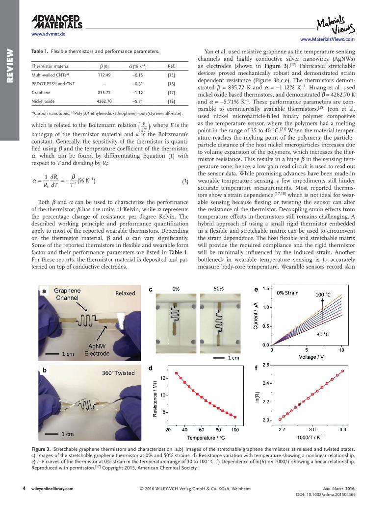
The HR can be measured manually from the radial artery at the wrist, from the carotid artery at the neck, or by listening directly to the heartbeat using a stethoscope. To measure the HR more accurately, electrical, optical, and strain sensors can be used. In the case of electrical measurement, skin electrodes are used to pick up the depolarization signal from the heart muscles. This technique is known as electrocardiography (ECG). In addition to health monitoring, ECG is a useful diagnostic technique for assessing the cardiovascular system. Although ECG measurements are conventionally done using 12 leads, the signal can be picked up by using two electrodes placed on the chest.[27] This allows the sensor designs in wear-able form factor. However, the signal intensity drops as the spacing between the electrodes is reduced.[28] Xu et al. used two electrodes in a band aid form factor as shown in Figure 4a. The sensor system was composed of electrodes, circuits, and radios for wireless communication in a soft microfluidic assembly; as a result, the complete system was flexible and stretchable[29] (Figure 4b). Figure 4c,d shows the obtained ECG signal using the flexible system. Similar wearable ECG config-uration is used with polymer,[30] carbon nanotube,[31] stretch-able elastomer,[32] and textile-based[33,34] electrodes. Since the ECG signal is periodic, the heart rate can be obtained from the R wave-to-R wave (RR) interval of the ECG signal.
Adv. Mater. 2016, DOI: 10.1002/adma.201504366
www.advmat.dewww.MaterialsViews.com
Figure 4. Electrocardiography (ECG) using a flexible and stretchable sensor system. a,b) Optical images of the sensor system on the forearm, with a pair of epidermal electrodes in self-similar serpentine mesh layouts (inset optical micrograph) for an a) undeformed state and b) compressed and twisted state. c) ECG acquired by using the device mounted on the sternum. d) A detailed view of the ECG signal shows the expected Q, R, and S waveforms. Reproduced with permission.[29] Copyright 2014, AAAS.
6 wileyonlinelibrary.com © 2016 WILEY-VCH Verlag GmbH & Co. KGaA, Weinheim
Rev
iew While the conventional gel-assisted Ag/AgCl electrodes
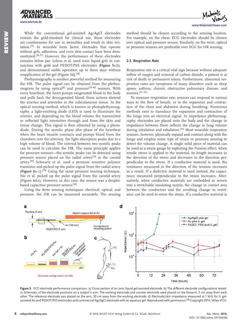
remain the gold-standard for clinical use, these electrodes are cumbersome for use in wearables and result in skin irri-tation.[35] In wearable form factor, electrodes that operate without gels, adhesives, and even skin contact have been dem-onstrated.[36,37] However, the performance of these electrodes remains below par. Leleux et al. used ionic liquid gels in con-junction with gold and PEDOT:PSS electrodes (Figure 5a,b), and demonstrated stable operation up to three days without reapplication of the gel (Figure 5d).[38]
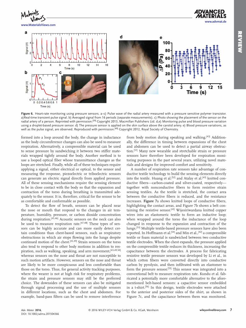
Plethysmography is another powerful method for measuring the HR. The pulse signal can be obtained from the plethys-mogram by using optical[6] and pressure[39,40] sensors. With every heartbeat, the heart pumps oxygenated blood to the body and pulls back the deoxygenated blood; these actions distend the arteries and arterioles in the subcutaneous tissue. In the optical sensing method, which is known as photoplethysmog-raphy, a light-emitting diode (LED) is used to illuminate the arteries, and depending on the blood volume the transmitted or reflected light intensities through and from the skin and tissue change. This signal is then obtained by using a photo-diode. During the systolic phase (the phase of the heartbeat when the heart muscle contracts and pumps blood from the chambers into the arteries), the light absorption peaks due to a high volume of blood. The interval between two systolic peaks can be used to calculate the HR. The same principle applies for pressure sensors—the systolic peaks can be detected using pressure sensor placed on the radial artery[39] or the carotid artery.[40] Schwartz et al. used a pressure sensitive polymer transistor and picked up the pulse signal from the radial artery (Figure 6a–c).[39] Using the same pressure sensing technique, Nie et al. picked up the pulse signal from the carotid artery (Figure 6d,e). However, in this case, the sensor was a droplet-based capacitive pressure sensor.[40]
Using the three sensing techniques: electrical, optical, and pressure, the HR can be measured accurately. The sensing
method should be chosen according to the sensing location. For example, on the chest, ECG electrodes should be chosen over optical and pressure sensor. Similarly, on the wrist, optical or pressure sensors are preferable over ECG for HR sensing.
2.3. Respiration Rate
Respiration rate is a critical vital sign because without adequate inflow of oxygen and removal of carbon dioxide, a patient is at risk of death or permanent injury. Furthermore, abnormal res-piration rates are symptoms of many disorders such as sleep apnea, asthma, chronic obstructive pulmonary disease, and anemia.[41–43]
To measure respiration rate, sensors can respond in various ways to the flow of breath, or to the expansion and contrac-tion of the chest and abdomen during breathing. Numerous methods exist to transduce the expansion and contraction of the lungs into an electrical signal. In impedance plethysmog-raphy, electrodes are placed onto the body and the change in impedance between them reflects the change in lung volume during inhalation and exhalation.[44] Most wearable respiration sensors, however, physically expand and contract along with the lungs and employ some type of strain or pressure sensing to detect the volume change. A single solid piece of material can be used as a strain gauge by exploiting the Poisson effect: when tensile stress is applied to the material, its length increases in the direction of the stress and decreases in the direction per-pendicular to the stress. If a conductive material is used, the resistance measured in the direction of the tension increases as a result. If a dielectric material is used instead, the capaci-tance measured perpendicular to the strain increases. Alter-natively, when conductive materials are embedded or woven into a stretchable insulating matrix, the change in contact area between the conductors and the resulting change in resist-ance can be used to sense the strain. If a conductive material is
Adv. Mater. 2016, DOI: 10.1002/adma.201504366
www.advmat.dewww.MaterialsViews.com
Figure 5. ECG electrode performance comparison. a) Cross-section of an ionic liquid gel-assisted electrode. b) The different electrode configurations tested. c) Schematic of the electrode positions on a subject’s arm. The working electrode and counter electrode were placed on the forearm, 5 cm away from each other. The reference electrode was placed on the arm, 30 cm away from the working electrode. d) Electrode/skin impedance measured at 1 kHz for IL gel-assisted Au and PEDOT:PSS electrodes and commercial Ag/AgCl electrode with an aqueous gel. Reproduced with permission.[38] Copyright 2014, Wiley-VCH.
7wileyonlinelibrary.com© 2016 WILEY-VCH Verlag GmbH & Co. KGaA, Weinheim
Rev
iew
formed into a loop around the body, the change in inductance as the body circumference changes can also be used to measure respiration. Alternatively, a compressible material can be used to sense pressure by sandwiching it between two stiffer mate-rials wrapped tightly around the body. Another method is to use a looped optical fiber whose transmittance changes as the loops are stretched. Finally, while all of these techniques require applying a signal, either electrical or optical, to the sensor and measuring the response, piezoelectric or triboelectric sensors can generate an electric signal directly from applied pressure. All of these sensing mechanisms require the sensing element to be in close contact with the body so that the expansion and contraction of the torso during breathing is transmitted ade-quately to the sensor. It is, therefore, critical for the sensor to be as comfortable and conformable as possible.
To detect the flow of breath, sensors can be placed near the nose or mouth that respond to the changes in air tem-perature, humidity, pressure, or carbon dioxide concentration during respiration.[45,46] Acoustic sensors on the neck can also be used to measure respiration rate.[47,48] These types of sen-sors can be highly accurate and can more easily detect cer-tain conditions than chest-based sensors, such as respiratory obstructions in which air stops flowing into the lungs despite continued motion of the chest.[45,49] Strain sensors on the torso also tend to respond to other body motions in addition to res-piration, such as walking, speaking, and arm movement,[43,49,50] whereas sensors on the nose and throat are not susceptible to such motion artifacts. However, sensors on the nose and throat are likely to be more conspicuous and less comfortable than those on the torso. Thus, for general activity tracking purposes, where the wearer is not at high risk for respiratory problems, the strain and pressure sensors may still be the preferred choice. The downsides of these sensors can also be mitigated through signal processing and the use of multiple sensors in different locations, such as the chest and abdomen. For example, band-pass filters can be used to remove interference
from body motion during speaking and walking.[43] Addition-ally, the difference in timing between expansions of the chest and abdomen can be used to detect a partial airway obstruc-tion.[51] Many new wearable and stretchable strain or pressure sensors have therefore been developed for respiration moni-toring purposes in the past several years, utilizing novel mate-rials and designs for improved comfort and sensitivity.
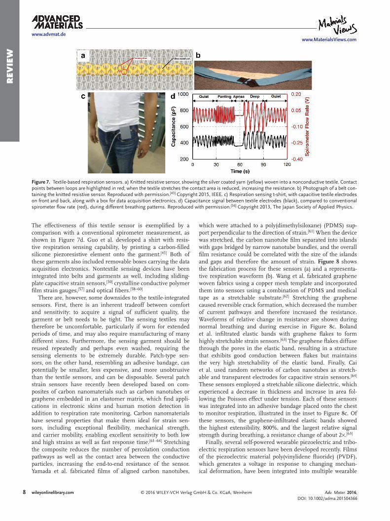
A number of respiration rate sensors take advantage of con-ductive textile technology to build the sensing elements directly into the textile. Huang et al.[52] and Atalay et al.[43] knitted con-ductive fibers—carbon-coated and silver-coated, respectively—together with nonconductive fibers to form resistive strain sensing textiles. As the textile is stretched, the contact area between the conductive fibers is reduced, and the resistance increases. Figure 7a shows knitted loops of conductive fibers, highlighting the contact areas, and Figure 7b shows a belt con-taining the resistive sensor.[43] Wijesiriwardana knitted copper wires into an elastomeric textile to form an inductive loop; when wrapped around the torso the inductance of the loop changed in response to the expansion and contraction of the lungs.[53] Multiple textile-based pressure sensors have also been reported. In Hoffmann et al.[54] and Min et al.,[42] a compressible textile or foam material is sandwiched between two conductive textile electrodes. When the chest expands, the pressure applied on the compressible textile reduces its thickness, increasing the capacitance between the electrodes. A process for fabricating resistive textile pressure sensors was developed by Li et al., in which cotton fibers were converted directly into conductive carbon by pyrolysis, and then infiltrated with an elastomer to form the pressure sensor.[55] This sensor was integrated into a conventional belt to measure respiration rate. Kundu et al. fab-ricated a potentially more comfortable alternative to the afore-mentioned belt-based sensors: a capacitive sensor embedded in a t-shirt.[56] In this design, textile electrodes were attached to the anterior and posterior sides of the shirt, as shown in Figure 7c, and the capacitance between them was monitored.
Adv. Mater. 2016, DOI: 10.1002/adma.201504366
www.advmat.dewww.MaterialsViews.com
Figure 6. Heart-rate monitoring using pressure sensors. a–c) Pulse wave of the radial artery measured with a pressure sensitive polymer transistor. a)Real-time transient pulse signal. b) Averaged signal from 16 periods (separate measurements). c) Photo showing the placement of the sensor on the radial artery of a person. Reprinted with permission.[39] Copyright 2013, Macmillan Publishers Ltd. d,e) Monitoring pulse and blood pressure variation using a droplet-based pressure sensor. d) The pressure sensor is applied on the skin surface above the carotid artery. e) Blood pressure variations, as well as the pulse signal, are observed. Reproduced with permission.[40] Copyright 2012, Royal Society of Chemistry.
8 wileyonlinelibrary.com © 2016 WILEY-VCH Verlag GmbH & Co. KGaA, Weinheim
Rev
iew
The effectiveness of this textile sensor is exemplified by a comparison with a conventional spirometer measurement, as shown in Figure 7d. Guo et al. developed a shirt with resis-tive respiration sensing capability, by printing a carbon-filled silicone piezoresistive element onto the garment.[41] Both of these garments also included removable boxes carrying the data acquisition electronics. Nontextile sensing devices have been integrated into belts and garments as well, including sliding-plate capacitive strain sensors,[50] crystalline conductive polymer film strain gauges,[57] and optical fibers.[58–60]
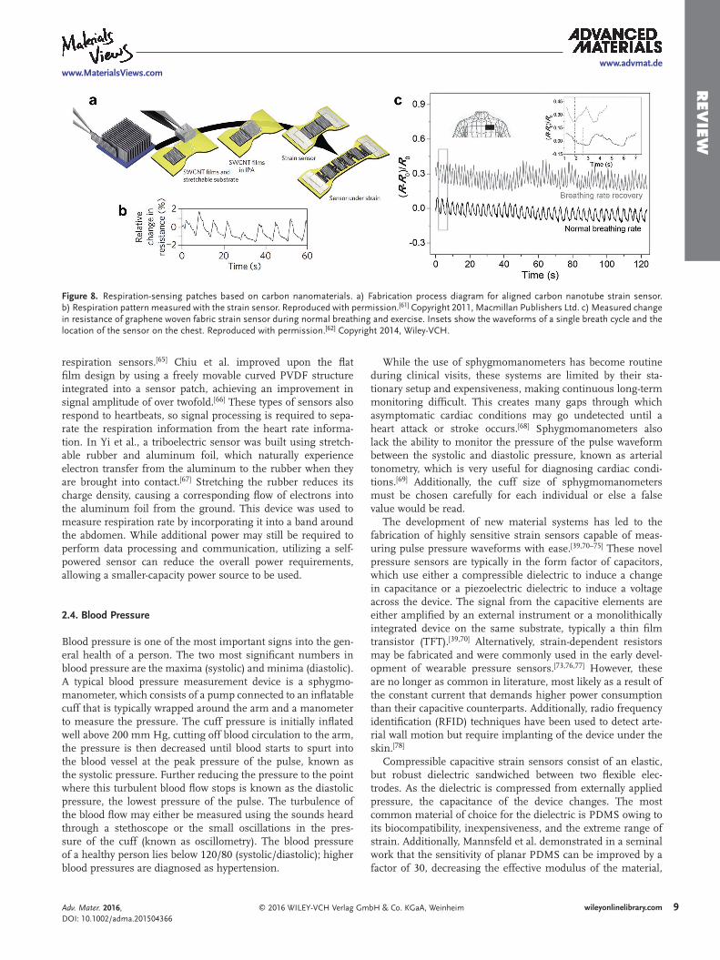
There are, however, some downsides to the textile-integrated sensors. First, there is an inherent tradeoff between comfort and sensitivity: to acquire a signal of sufficient quality, the garment or belt needs to be tight. The sensing textiles may therefore be uncomfortable, particularly if worn for extended periods of time, and may also require manufacturing of many different sizes. Furthermore, the sensing garment should be reused repeatedly and perhaps even washed, requiring the sensing elements to be extremely durable. Patch-type sen-sors, on the other hand, resembling an adhesive bandage, can potentially be smaller, less expensive, and more unobtrusive than the textile sensors, and can be disposable. Several patch strain sensors have recently been developed based on com-posites of carbon nanomaterials such as carbon nanotubes or graphene embedded in an elastomer matrix, which find appli-cations in electronic skins and human motion detection in addition to respiration rate monitoring. Carbon nano materials have several properties that make them ideal for strain sen-sors, including exceptional flexibility, mechanical strength, and carrier mobility, enabling excellent sensitivity to both low and high strains as well as fast response time.[61–64] Stretching the composite reduces the number of percolation conduction pathways as well as the contact area between the conductive particles, increasing the end-to-end resistance of the sensor. Yamada et al. fabricated films of aligned carbon nanotubes,
which were attached to a poly(dimethylsiloxane) (PDMS) sup-port perpendicular to the direction of strain.[61] When the device was stretched, the carbon nanotube film separated into islands with gaps bridged by narrow nanotube bundles, and the overall film resistance could be correlated with the size of the islands and gaps and therefore the amount of strain. Figure 8 shows the fabrication process for these sensors (a) and a representa-tive respiration waveform (b). Wang et al. fabricated graphene woven fabrics using a copper mesh template and incorporated them into sensors using a combination of PDMS and medical tape as a stretchable substrate.[62] Stretching the graphene caused reversible crack formation, which decreased the number of current pathways and therefore increased the resistance. Waveforms of relative change in resistance are shown during normal breathing and during exercise in Figure 8c. Boland et al. infiltrated elastic bands with graphene flakes to form highly stretchable strain sensors.[63] The graphene flakes diffuse through the pores in the elastic band, resulting in a structure that exhibits good conduction between flakes but maintains the very high stretchability of the elastic band. Finally, Cai et al. used random networks of carbon nanotubes as stretch-able and transparent electrodes for capacitive strain sensors.[64] These sensors employed a stretchable silicone dielectric, which experienced a decrease in thickness and increase in area fol-lowing the Poisson effect under tension. Each of these sensors was integrated into an adhesive bandage placed onto the chest to monitor respiration, illustrated in the inset to Figure 8c. Of these sensors, the graphene-infiltrated elastic bands showed the highest extensibility, 800%, and the largest relative signal strength during breathing, a resistance change of about 2×.[63]
Finally, several self-powered wearable piezoelectric and tribo-electric respiration sensors have been developed recently. Films of the piezoelectric material poly(vinylidene fluoride) (PVDF), which generates a voltage in response to changing mechan-ical deformation, have been integrated into multiple wearable
Adv. Mater. 2016, DOI: 10.1002/adma.201504366
www.advmat.dewww.MaterialsViews.com
Figure 7. Textile-based respiration sensors. a) Knitted resistive sensor, showing the silver coated yarn (yellow) woven into a nonconductive textile. Contact points between loops are highlighted in red; when the textile stretches the contact area is reduced, increasing the resistance. b) Photograph of a belt con-taining the knitted resistive sensor. Reproduced with permission.[43] Copyright 2015, IEEE. c) Respiration sensing t-shirt, with capacitive textile electrodes on front and back, along with a box for data acquisition electronics. d) Capacitance signal between textile electrodes (black), compared to conventional spirometer flow rate (red), during different breathing patterns. Reproduced with permission.[56] Copyright 2013, The Japan Society of Applied Physics.
9wileyonlinelibrary.com© 2016 WILEY-VCH Verlag GmbH & Co. KGaA, Weinheim
Rev
iew
respiration sensors.[65] Chiu et al. improved upon the flat film design by using a freely movable curved PVDF structure integrated into a sensor patch, achieving an improvement in signal amplitude of over twofold.[66] These types of sensors also respond to heartbeats, so signal processing is required to sepa-rate the respiration information from the heart rate informa-tion. In Yi et al., a triboelectric sensor was built using stretch-able rubber and aluminum foil, which naturally experience electron transfer from the aluminum to the rubber when they are brought into contact.[67] Stretching the rubber reduces its charge density, causing a corresponding flow of electrons into the aluminum foil from the ground. This device was used to measure respiration rate by incorporating it into a band around the abdomen. While additional power may still be required to perform data processing and communication, utilizing a self-powered sensor can reduce the overall power requirements, allowing a smaller-capacity power source to be used.
2.4. Blood Pressure
Blood pressure is one of the most important signs into the gen-eral health of a person. The two most significant numbers in blood pressure are the maxima (systolic) and minima (diastolic). A typical blood pressure measurement device is a sphygmo-manometer, which consists of a pump connected to an inflatable cuff that is typically wrapped around the arm and a manometer to measure the pressure. The cuff pressure is initially inflated well above 200 mm Hg, cutting off blood circulation to the arm, the pressure is then decreased until blood starts to spurt into the blood vessel at the peak pressure of the pulse, known as the systolic pressure. Further reducing the pressure to the point where this turbulent blood flow stops is known as the diastolic pressure, the lowest pressure of the pulse. The turbulence of the blood flow may either be measured using the sounds heard through a stethoscope or the small oscillations in the pres-sure of the cuff (known as oscillometry). The blood pressure of a healthy person lies below 120/80 (systolic/diastolic); higher blood pressures are diagnosed as hypertension.
While the use of sphygmomanometers has become routine during clinical visits, these systems are limited by their sta-tionary setup and expensiveness, making continuous long-term monitoring difficult. This creates many gaps through which asymptomatic cardiac conditions may go undetected until a heart attack or stroke occurs.[68] Sphygmomanometers also lack the ability to monitor the pressure of the pulse waveform between the systolic and diastolic pressure, known as arterial tonometry, which is very useful for diagnosing cardiac condi-tions.[69] Additionally, the cuff size of sphygmomanometers must be chosen carefully for each individual or else a false value would be read.
The development of new material systems has led to the fabrication of highly sensitive strain sensors capable of meas-uring pulse pressure waveforms with ease.[39,70–75] These novel pressure sensors are typically in the form factor of capacitors, which use either a compressible dielectric to induce a change in capacitance or a piezoelectric dielectric to induce a voltage across the device. The signal from the capacitive elements are either amplified by an external instrument or a monolithically integrated device on the same substrate, typically a thin film transistor (TFT).[39,70] Alternatively, strain-dependent resistors may be fabricated and were commonly used in the early devel-opment of wearable pressure sensors.[73,76,77] However, these are no longer as common in literature, most likely as a result of the constant current that demands higher power consumption than their capacitive counterparts. Additionally, radio frequency identification (RFID) techniques have been used to detect arte-rial wall motion but require implanting of the device under the skin.[78]
Compressible capacitive strain sensors consist of an elastic, but robust dielectric sandwiched between two flexible elec-trodes. As the dielectric is compressed from externally applied pressure, the capacitance of the device changes. The most common material of choice for the dielectric is PDMS owing to its biocompatibility, inexpensiveness, and the extreme range of strain. Additionally, Mannsfeld et al. demonstrated in a seminal work that the sensitivity of planar PDMS can be improved by a factor of 30, decreasing the effective modulus of the material,
Adv. Mater. 2016, DOI: 10.1002/adma.201504366
www.advmat.dewww.MaterialsViews.com
Figure 8. Respiration-sensing patches based on carbon nanomaterials. a) Fabrication process diagram for aligned carbon nanotube strain sensor. b) Respiration pattern measured with the strain sensor. Reproduced with permission.[61] Copyright 2011, Macmillan Publishers Ltd. c) Measured change in resistance of graphene woven fabric strain sensor during normal breathing and exercise. Insets show the waveforms of a single breath cycle and the location of the sensor on the chest. Reproduced with permission.[62] Copyright 2014, Wiley-VCH.
10 wileyonlinelibrary.com © 2016 WILEY-VCH Verlag GmbH & Co. KGaA, Weinheim
Rev
iew and the relaxation time can be reduced to by a factor of 104, by
molding the surface into microstructured pyramids.[79] These high sensitivities and fast relaxation times enabled a new set of devices that could measure blood pressure precisely enough for arterial tonometry. Further examining the effects of these microstructures, Tee et al. have shown that smaller sidewall angles and larger pyramid spacing led to a decrease in the effec-tive modulus, improving sensitivity to 0.2 kPa−1.[80] However, the attempt to measure pulse pressure was made difficult by the fact the pressure of the finger on the sensor was far greater than the pulse and by the nonlinearity of the sensor, which decreased sensitivity to the small pressure variations from the finger’s pulse at high background pressures. The effective modulus of the PDMS dielectric may also be reduced by cre-ating a porous film[81] and roughening the surface by casting PDMS on a rough substrate.[73] Wang et al. demonstrated that casting PDMS on an inherently microtextured substrate such as silk and depositing stretchable and conformal carbon nano-tube conductors creates a pulse pressure sensor with a sensi-tivity of 1.8 kPa−1.[73] In this design, the change in contact area between two carbon nanotube coated rough PDMS films, and the resulting change in resistance between them, allowed the pressure to be sensed. An ionic fluid may also be used as a die-lectric, as reported by Li et al., with an electrical double layer acting as the main source of capacitance with a sensitivity of 0.45 kPa−1.[71] The relaxation time was sufficiently fast to reli-ably measure arterial pulse pressure.
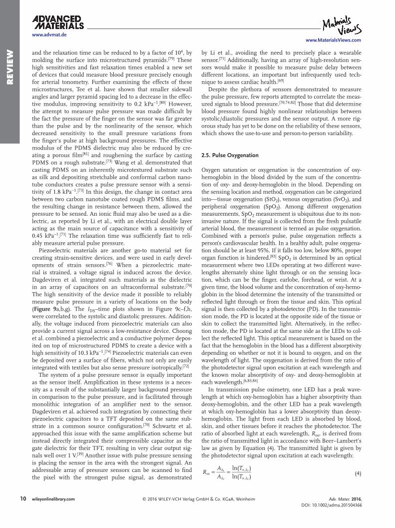
Piezoelectric materials are another go-to material set for creating strain-sensitive devices, and were used in early devel-opments of strain sensors.[76] When a piezoelectric mate-rial is strained, a voltage signal is induced across the device. Dagdeviren et al. integrated such materials as the dielectric in an array of capacitors on an ultraconformal substrate.[70] The high sensitivity of the device made it possible to reliably measure pulse pressure in a variety of locations on the body (Figure 9a,b,g). The IDS–time plots shown in Figure 9c–f,h, were correlated to the systolic and diastolic pressures. Addition-ally, the voltage induced from piezoelectric materials can also provide a current signal across a low-resistance device. Choong et al. combined a piezoelectric and a conductive polymer depos-ited on top of microstructured PDMS to create a device with a high sensitivity of 10.3 kPa−1.[74] Piezoelectric materials can even be deposited over a surface of fibers, which not only are easily integrated with textiles but also sense pressure isotropically.[72]
The system of a pulse pressure sensor is equally important as the sensor itself. Amplification in these systems is a neces-sity as a result of the substantially larger background pressure in comparison to the pulse pressure, and is facilitated through monolithic integration of an amplifier next to the sensor. Dagdeviren et al. achieved such integration by connecting their piezoelectric capacitors to a TFT deposited on the same sub-strate in a common source configuration.[70] Schwartz et al. approached this issue with the same amplification scheme but instead directly integrated their compressible capacitor as the gate dielectric for their TFT, resulting in very clear output sig-nals well over 1 V.[39] Another issue with pulse pressure sensing is placing the sensor in the area with the strongest signal. An addressable array of pressure sensors can be scanned to find the pixel with the strongest pulse signal, as demonstrated
by Li et al., avoiding the need to precisely place a wearable sensor.[71] Additionally, having an array of high-resolution sen-sors would make it possible to measure pulse delay between different locations, an important but infrequently used tech-nique to assess cardiac health.[69]
Despite the plethora of sensors demonstrated to measure the pulse pressure, few reports attempted to correlate the meas-ured signals to blood pressure.[70,74,82] Those that did determine blood pressure found highly nonlinear relationships between systolic/diastolic pressures and the sensor output. A more rig-orous study has yet to be done on the reliability of these sensors, which shows the use-to-use and person-to-person variability.
2.5. Pulse Oxygenation
Oxygen saturation or oxygenation is the concentration of oxy-hemoglobin in the blood divided by the sum of the concentra-tion of oxy- and deoxy-hemoglobin in the blood. Depending on the sensing location and method, oxygenation can be categorized into—tissue oxygenation (StO2), venous oxygenation (SvO2), and peripheral oxygenation (SpO2). Among different oxygenation measurements, SpO2 measurement is ubiquitous due to its non-invasive nature. If the signal is collected from the fresh pulsatile arterial blood, the measurement is termed as pulse oxygenation. Combined with a person’s pulse, pulse oxygenation reflects a person’s cardiovascular health. In a healthy adult, pulse oxygena-tion should be at least 95%. If it falls too low, below 80%, proper organ function is hindered.[83] SpO2 is determined by an optical measurement where two LEDs operating at two different wave-lengths alternately shine light through or on the sensing loca-tion, which can be the finger, earlobe, forehead, or wrist. At a given time, the blood volume and the concentration of oxy-hemo-globin in the blood determine the intensity of the transmitted or reflected light through or from the tissue and skin. This optical signal is then collected by a photodetector (PD). In the transmis-sion mode, the PD is located at the opposite side of the tissue or skin to collect the transmitted light. Alternatively, in the reflec-tion mode, the PD is located at the same side as the LEDs to col-lect the reflected light. This optical measurement is based on the fact that the hemoglobin in the blood has a different absorptivity depending on whether or not it is bound to oxygen, and on the wavelength of light. The oxygenation is derived from the ratio of the photodetector signal upon excitation at each wavelength and the known molar absorptivity of oxy- and deoxy-hemoglobin at each wavelength.[6,83,84]
In transmission pulse oximetry, one LED has a peak wave-length at which oxy-hemoglobin has a higher absorptivity than deoxy-hemoglobin, and the other LED has a peak wavelength at which oxy-hemoglobin has a lower absorptivity than deoxy-hemoglobin. The light from each LED is absorbed by blood, skin, and other tissues before it reaches the photodetector. The ratio of absorbed light at each wavelength, Ros, is derived from the ratio of transmitted light in accordance with Beer–Lambert’s law as given by Equation (4). The transmitted light is given by the photodetector signal upon excitation at each wavelength:
= =λ
λ
λ
λ
ln( )
ln( )os
,
,
1
2
1
2
RA
A
T
Tn
n (4)
Adv. Mater. 2016, DOI: 10.1002/adma.201504366
www.advmat.dewww.MaterialsViews.com
11wileyonlinelibrary.com© 2016 WILEY-VCH Verlag GmbH & Co. KGaA, Weinheim
Rev
iew
Adv. Mater. 2016, DOI: 10.1002/adma.201504366
www.advmat.dewww.MaterialsViews.com
Figure 9. Blood-pressure-wave measurements on the wrist and neck using a pressure-sensitive transistor. a) Photograph of the sensor placed on a wrist (scale bar, 2 cm). b) Magnified view (scale bar, 1 cm). c) IDS–time plot for a sensor mounted on the wrist. d) IDS–time plot for data in the region indicated by the dashed box in c. e) IDS–time plot for the sensor while reading pressure on the wrist before, during and after application of pressure on the arm using a commercial pneumatic cuff. f) IDS–time plot for data in the region indicated by the dashed box in (e). Photograph of a sensor placed on ((g); scale bar, 1 cm) neck. h) Blood pressure from the neck. Reproduced with permission.[70] Copyright 2014, Macmillan Publishers Ltd.
12 wileyonlinelibrary.com © 2016 WILEY-VCH Verlag GmbH & Co. KGaA, Weinheim
Rev
iew The arterial oxygen saturation, SaO2, is then derived from Ros
and the molar extinction coefficient of oxy-hemoglobin (ελ ,HbO2)
and deoxy-hemoglobin (ελ ,Hb) at each wavelength:
ε εε ε ε ε
=−
− + −λ λ
λ λ λ λ( )
( ) ( )a 2 os
,Hb ,Hb os
,Hb ,HbO ,HbO ,Hb os
1 2
1 1 2 2 2 2
S O RR
R
(5)
Organic optoelectronics are a prime candidate for use in pulse oximetry because they are solution processable at low temperatures compatible with fabrication on flexible plastic substrates. Unlike the inorganic optoelectronics used in com-mercially available pulse oximeters, the flexible form factors of organic LEDs (OLEDs) and organic photodetectors (OPDs) allow for an oximeter that has a conformal fit to the human body.[6,85]
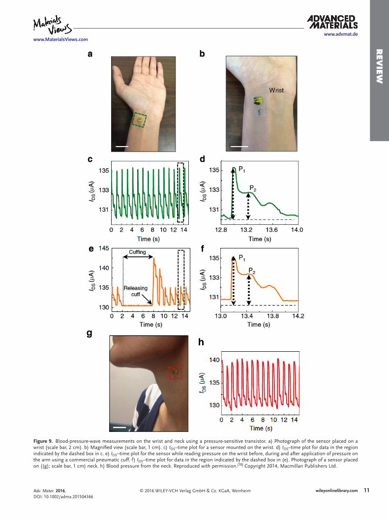
Lochner et al. have demonstrated a transmission-mode pulse oximetry probe composed of solution-processed OLEDs and a printed OPD.[6] The active layer of the OPD is a bulk hetero-junction donor/acceptor blend of [6,6]-phenyl C71-butyric acid methyl ester (PC71BM) and poly({4,8-bis[(2-ethylhexyl)oxy]-benzo[1,2-b:4,5-b′]dithiophene-2,6-diyl}{3-fluoro-2-[(2-ethyl-hexyl)carbonyl]thieno[3,4-b]thiophenediyl}) (PTB7). The active layer of each OLED is made from a blend of polyfluorenes, a family of stable fluorescent polymers. All-organic optoelectronic devices were processed in a way that is compatible with flexible plastic substrates, enabling devices that can have a conformal fit to the human body. In this oximeter, one OLED emits in the red spectrum with a peak wavelength at 626 nm and the other emits in the green spectrum with a peak wavelength at 532 nm, a novel combination of wavelengths compared to the conven-tional red and infrared wavelengths used in commercially avail-able pulse oximeters. A green OLED was chosen in place of a near-infrared OLED due to green emissive materials′ superior efficiency and solution processability at this point in time. This combination of solution processed red and green OLEDs with printed OPD successfully demonstrated the absolute meas-urement of human pulse and arterial oxygen saturation using organic optoelectronics (Figure 10).
An alternative approach to using OLEDs and OPDs for pulse oximetry has been demonstrated by Bansal et al., who
used one OLED made from poly[2-(3′,7′-dimethyloctyloxy)-5-methoxy-1,4-phenylenevinylene] or OC1C10-PPV (with peak emission in the red and tail in the NIR) and two OPDs made from PTB7:PC70BM (with an unfiltered absorption max-imum at 690 nm) to perform pulse oximetry using reflected light rather than transmitted light.[85] The OLED is placed in between the two OPDs, each with a different filter to allow the OPD to read light with a peak wavelength of 610 or 700 nm. The OLED and OPD were placed onto a subject’s forearm with 20 mm spacing in order to probe the oxygen saturation of muscle tissue, and successfully showed the change in the concentration of oxy-hemoglobin in the tissue upon induction and termination of ischemia induced in the arm.
With a focus away from making the optoelectronics them-selves flexible, Rothmaier et al. have shown a flexible and wear-able pulse oximeter using inorganic light sources and detectors that are not form-fitting to the human body by creating a textile optical fiber glove to transmit the optical signals from the light source, through the forefinger tip, and back to the detector.[86] Plastic optical fibers (POF) made from poly(methyl methacrylate) (PMMA) were woven or embroidered into polyester fibers. Their wearability while taking oxygenation measurements was demon-strated by integrating the optical fiber textile into the forefinger tip of a glove in order to take pulse oximetry measurements. Organic and textile optoelectronics are extremely promising for novel implementations of pulse and tissue oximetry. While textile optoelectronics can be integrated into clothing, organic optoelec-tronics on flexible substrates can be adhered directly to the skin with a secure fit. Even in commercially available pulse oximeters, motion artifacts and ambient light interference are known prob-lems that hinder the measurement accuracy. By adhering the sensor closely to the skin and letting it flex and move with the skin, the noise from ambient light can be reduced as well as the impact of motion artifacts.[6]
2.6. Blood Glucose
According to the World Health Organization, 9% of adults worldwide have diabetes.[87] Glucose monitoring is vital to
Adv. Mater. 2016, DOI: 10.1002/adma.201504366
www.advmat.dewww.MaterialsViews.com
Figure 10. All-organic optoelectronic pulse oximeter. a) Pulse oximetry transmission-mode finger probe composed of solution-processed red and green organic light-emitting diodes (OLEDs) and printed organic photodiodes (OPDs). b) Photoplethysmogram (PPG) signal upon excitation by light transmitted through a finger from green and red OLEDs (top two panels, respectively), heart rate extracted from PPG signal (third panel from the top), ratio of PPG signal upon excitation by red and green light (Ros) (second panel from bottom), and arterial blood oxygen saturation (SaO2) derived from Ros (bottom panel). Reproduced with permission.[6] Copyright 2014, Macmillan Publishers Ltd.
13wileyonlinelibrary.com© 2016 WILEY-VCH Verlag GmbH & Co. KGaA, Weinheim
Rev
iew
maintaining the health and quality of life of diabetics and must be done frequently every day. Even the most noninvasive com-mercially available glucose monitors require patient’s blood. New electronics fabrication techniques on flexible substrates have recently enabled noninvasive wearable glucose sensors that monitor the glucose concentration without drawing blood.
Noninvasive glucose measurement devices have been devel-oped to measure glucose concentration with an enzyme-based electrochemical sensor.[88–93] The main enzyme utilized by the measurements is glucose oxidase (GOD). In the presence of GOD, D-glucose and O2 form H2O2 and D-gluconolactone. The H2O2 oxidizes to produce hydrogen, oxygen, and free electrons. These free electrons are measured as sensor current; the higher the current, the more free electrons, the higher the blood glu-cose concentration.
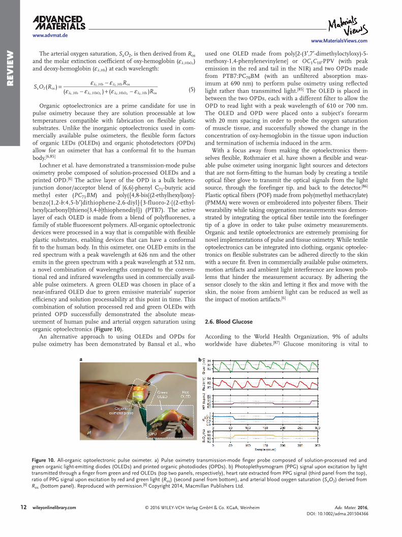
An enzymatic sensor that monitors the glucose level of tears in a wearable contact lens form factor (Figure 11) has been successfully demonstrated.[94] The sensor is composed of three Ti/Pd/Pt electrodes (working, counter, and reference) fabri-cated on a PET substrate. The working and counter electrodes were fabricated as concentric rings with the bare PET surface in between used to immobilize GOD. A GOD layer was depos-ited onto the sensor area and retained with a concurrently deposited titania sol–gel membrane. A Nafion coating was deposited over the GOD/titania sol–gel membrane in order to ensure sensor accuracy by decreasing interference in the measurement from ascorbic acid, lactate, and urea. 400 mV was applied between the working and reference electrodes and the counter electrode served as the current drain. The current generated in the sensor was measured in the presence of a con-centrated glucose solution, exhibiting an increase proportional to the amount of glucose present with a 240 μA cm−2 mM−1 sensitivity (Figure 11) and 0.01−6 mM detection range.
A wearable enzyme-based amperometric glucose sensor has also been demonstrated in a temporary tattoo form factor adhered to the skin.[93] In the tattoo, reverse iontophoretic extraction is used to transport interstitial glucose from the skin to the sensor. Reverse iontophoresis uses a small cur-rent applied between two electrodes (in this case made from
Ag/AgCl ink) to move sodium ions through the skin toward the sensing electrodes (in this case made from Ag/AgCl or Prussian blue ink). As the sodium ions flow across the skin, a flow of interstitial skin fluid is induced, transporting the glu-cose contained within to the sensing area. The current den-sity employed in iontophoresis should be low enough to not cause skin irritation; Bandokar et al. applied 0.2 mA cm−2 for 10 min prior to recording the enzymatic amperometric glucose response of the sensor with −0.01 mV applied between the working and reference electrodes. The tattoo sensor is able to measure glucose concentration from the interstitial skin fluid with a sensitivity of 23 nA μM−1 and 3−100 μM detection range.
In addition to measuring the amperometric response between working electrodes, an alternative enzymatic glucose sensing paradigm measures the drain-source current and Dirac point shifts in graphene field effect transistors (FETs) as a func-tion of glucose concentration.[91,92] In the graphene FET sen-sors, GOD is also used and reacts with glucose to form H2O2. H2O2 subsequently reacts with the graphene channel of the FET, effectively doping it and changing its conductance. Thus, the FET’s Dirac point will shift and the source/drain current will be modulated in the presence of glucose.
Kwak et al. demonstrated a CVD-grown graphene FET glu-cose sensor on a flexible PET substrate.[92] Source and drain electrodes were fabricated from conductive Ag paint and epoxy resin on either end of the graphene channel, which was modi-fied with a 1-pyrenebutanoic acid succinimidyl ester linker to facilitate GOD adhesion. To test the responsivity of the sensor, a Pt wire suspended in a glucose/H2O2 solution was used as the top gate electrode. A Dirac point shift and linear change in drain/source current were observed in a 3.3−10.9 mM glucose detection range.
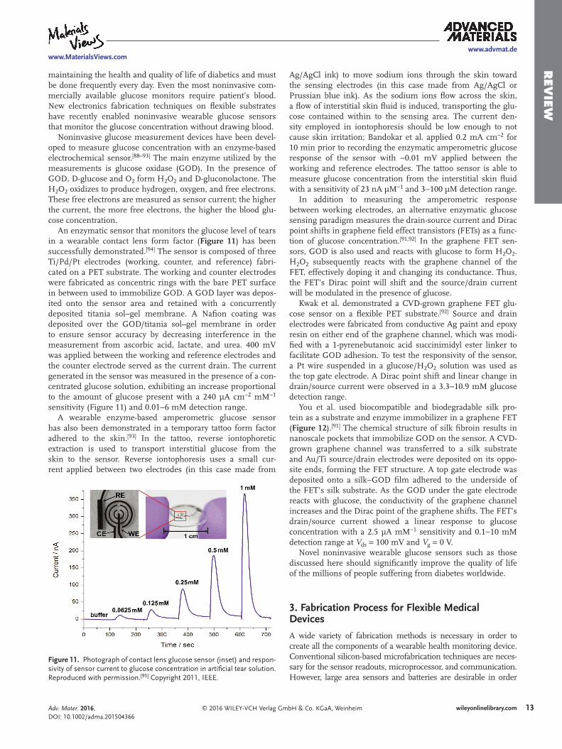
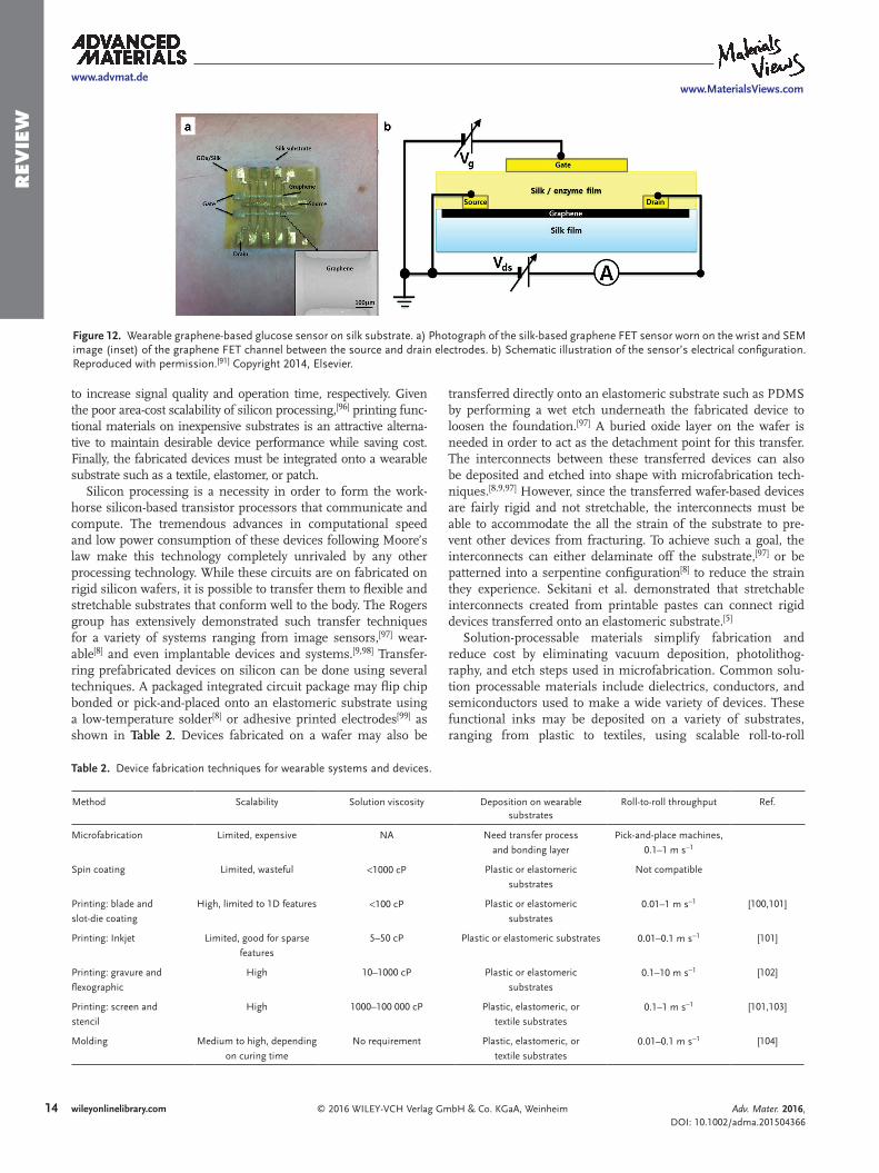
You et al. used biocompatible and biodegradable silk pro-tein as a substrate and enzyme immobilizer in a graphene FET (Figure 12).[91] The chemical structure of silk fibroin results in nanoscale pockets that immobilize GOD on the sensor. A CVD-grown graphene channel was transferred to a silk substrate and Au/Ti source/drain electrodes were deposited on its oppo-site ends, forming the FET structure. A top gate electrode was deposited onto a silk−GOD film adhered to the underside of the FET’s silk substrate. As the GOD under the gate electrode reacts with glucose, the conductivity of the graphene channel increases and the Dirac point of the graphene shifts. The FET’s drain/source current showed a linear response to glucose concentration with a 2.5 μA mM−1 sensitivity and 0.1−10 mM detection range at Vds = 100 mV and Vg = 0 V.
Novel noninvasive wearable glucose sensors such as those discussed here should significantly improve the quality of life of the millions of people suffering from diabetes worldwide.
3. Fabrication Process for Flexible Medical Devices
A wide variety of fabrication methods is necessary in order to create all the components of a wearable health monitoring device. Conventional silicon-based microfabrication techniques are neces-sary for the sensor readouts, microprocessor, and communication. However, large area sensors and batteries are desirable in order
Adv. Mater. 2016, DOI: 10.1002/adma.201504366
www.advmat.dewww.MaterialsViews.com
Figure 11. Photograph of contact lens glucose sensor (inset) and respon-sivity of sensor current to glucose concentration in artificial tear solution. Reproduced with permission.[95] Copyright 2011, IEEE.
14 wileyonlinelibrary.com © 2016 WILEY-VCH Verlag GmbH & Co. KGaA, Weinheim
Rev
iew
to increase signal quality and operation time, respectively. Given the poor area-cost scalability of silicon processing,[96] printing func-tional materials on inexpensive substrates is an attractive alterna-tive to maintain desirable device performance while saving cost. Finally, the fabricated devices must be integrated onto a wearable substrate such as a textile, elastomer, or patch.
Silicon processing is a necessity in order to form the work-horse silicon-based transistor processors that communicate and compute. The tremendous advances in computational speed and low power consumption of these devices following Moore’s law make this technology completely unrivaled by any other processing technology. While these circuits are on fabricated on rigid silicon wafers, it is possible to transfer them to flexible and stretchable substrates that conform well to the body. The Rogers group has extensively demonstrated such transfer techniques for a variety of systems ranging from image sensors,[97] wear-able[8] and even implantable devices and systems.[9,98] Transfer-ring prefabricated devices on silicon can be done using several techniques. A packaged integrated circuit package may flip chip bonded or pick-and-placed onto an elastomeric substrate using a low-temperature solder[8] or adhesive printed electrodes[99] as shown in Table 2. Devices fabricated on a wafer may also be
transferred directly onto an elastomeric substrate such as PDMS by performing a wet etch underneath the fabricated device to loosen the foundation.[97] A buried oxide layer on the wafer is needed in order to act as the detachment point for this transfer. The interconnects between these transferred devices can also be deposited and etched into shape with microfabrication tech-niques.[8,9,97] However, since the transferred wafer-based devices are fairly rigid and not stretchable, the interconnects must be able to accommodate the all the strain of the substrate to pre-vent other devices from fracturing. To achieve such a goal, the interconnects can either delaminate off the substrate,[97] or be patterned into a serpentine configuration[8] to reduce the strain they experience. Sekitani et al. demonstrated that stretchable interconnects created from printable pastes can connect rigid devices transferred onto an elastomeric substrate.[5]
Solution-processable materials simplify fabrication and reduce cost by eliminating vacuum deposition, photolithog-raphy, and etch steps used in microfabrication. Common solu-tion processable materials include dielectrics, conductors, and semiconductors used to make a wide variety of devices. These functional inks may be deposited on a variety of substrates, ranging from plastic to textiles, using scalable roll-to-roll
Adv. Mater. 2016, DOI: 10.1002/adma.201504366
www.advmat.dewww.MaterialsViews.com
Figure 12. Wearable graphene-based glucose sensor on silk substrate. a) Photograph of the silk-based graphene FET sensor worn on the wrist and SEM image (inset) of the graphene FET channel between the source and drain electrodes. b) Schematic illustration of the sensor’s electrical configuration. Reproduced with permission.[91] Copyright 2014, Elsevier.
Table 2. Device fabrication techniques for wearable systems and devices.
Method Scalability Solution viscosity Deposition on wearable substrates
Roll-to-roll throughput Ref.
Microfabrication Limited, expensive NA Need transfer process
and bonding layer
Pick-and-place machines,
0.1–1 m s−1
Spin coating Limited, wasteful <1000 cP Plastic or elastomeric
substrates
Not compatible
Printing: blade and
slot-die coating
High, limited to 1D features <100 cP Plastic or elastomeric
substrates0.01–1 m s−1 [100,101]
Printing: Inkjet Limited, good for sparse
features
5–50 cP Plastic or elastomeric substrates 0.01–0.1 m s−1 [101]
Printing: gravure and
flexographic
High 10–1000 cP Plastic or elastomeric
substrates0.1–10 m s−1 [102]
Printing: screen and
stencil
High 1000–100 000 cP Plastic, elastomeric, or
textile substrates0.1–1 m s−1 [101,103]
Molding Medium to high, depending
on curing time
No requirement Plastic, elastomeric, or
textile substrates0.01–0.1 m s−1 [104]
15wileyonlinelibrary.com© 2016 WILEY-VCH Verlag GmbH & Co. KGaA, Weinheim
Rev
iew
compatible printing methods. Despite the limited performance of printed transistors, printing is ideal for sensors. Not only is cost reduced, but larger sensors can be more easily printed than microfabricated since the process is not limited by wafer throughput. Additionally, the need for any transfer processes may be eliminated since the sensor may be printed on a wear-able substrate. A vast range of wearable sensors such as tem-perature sensors,[18] bioelectronic electrodes,[4] biosensors,[105] and electrochemical sensors[106,107] have been demonstrated by printing solution-processable functional inks. The most common solution processing technique for low-viscosity inks of <100 centipoise (cP) is spin coating. While this does pro-duce a uniform film, it does not use ink parsimoniously and is difficult to scale to large areas.[101] A more efficient method of printing uniform films from low viscosity inks can be achieved by doctor blade coating,[6] slot-die coating,[101] and spray coating.[108] Patterning low viscosity inks may either be achieved via patterning the surface of a substrate to direct wetting[100] or inkjet printing.[101] Inkjet printing is well adept for depositing sparse, thin designs but becomes difficult for larger-sized fea-tures.[7,109,110] Gravure and flexographic printing require higher viscosity inks for reliable printing.[101] While formulating high viscosity inks necessitates the use of highly soluble solutes, features as small as 5 μm can be reliably printed at speeds approaching one meter per second.[102] Functional materials with a high paste-like viscosity (1000–100 000 cP) can be depos-ited via screen printing and stencil printing.[103,111] Molding is also compatible with roll-to-roll manufacturing, but the flow rate into the mold pattern and curing speed is a critical factor in determining the maximum throughput speed.[104] Solution pro-cessing can even be integrated with textile substrates, which are conformal and robust. However due to the high roughness and porosity of textiles, they are best suited for devices that require thick active layers such as batteries.[112,113]
The low power and high speed of silicon-based electronics coupled with the low-cost area scalability, facile wearable
substrate integration and high performance of printable sen-sors means all wearable systems will be heterogeneous. Conse-quently, it will be necessary to integrate the transfer process for silicon processors and printing of the sensors onto the same line to maximize efficacy. Additionally, proper printing tech-niques will need to be chosen which deposit the necessary film thicknesses to maximize energy storage in the batteries, mini-mize energy consumption by the sensors, and make the oper-ating voltages between the silicon and printed-based devices compatible.
4. Medical Sensor Data Processing and Transmission
Sensors are essentially transducers—biosensors transduce biosig-nals to different kind of electrical signals, such as voltage, current, impedance, and capacitance. However, these electrical signals require preprocessing before they can be interpreted to a mean-ingful number or signal that can be used for medical monitoring or diagnostics. In this section, the workflow of a complete bio-sensor system is discussed. Fabricated biosensors are often con-nected to an analog front end, where the analog electrical signal is filtered and amplified. A microcontroller (MCU) or micropro-cessor (MPU) then reads the signal after digitizing the analog signal using an analog to digital converter (ADC). Next, the data are processed using algorithms running on the MCU/MPU and finally sent out to a computer or portable device via wired or wire-less interface for data interpretation and visualization.
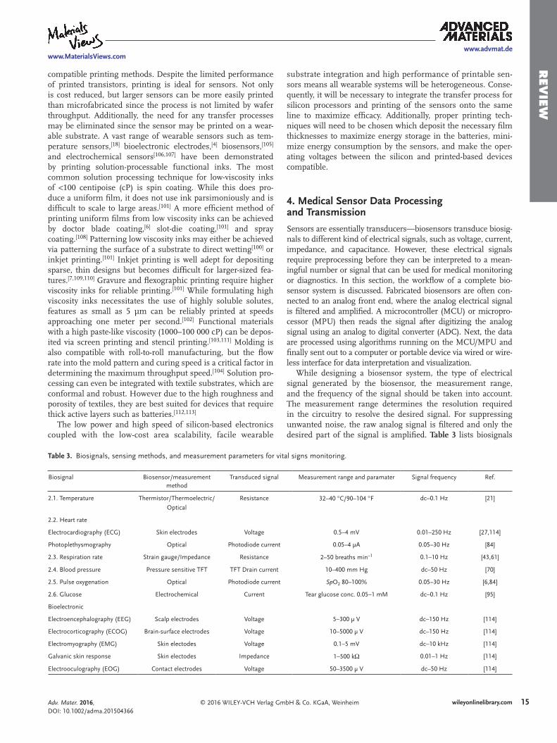
While designing a biosensor system, the type of electrical signal generated by the biosensor, the measurement range, and the frequency of the signal should be taken into account. The measurement range determines the resolution required in the circuitry to resolve the desired signal. For suppressing unwanted noise, the raw analog signal is filtered and only the desired part of the signal is amplified. Table 3 lists biosignals
Adv. Mater. 2016, DOI: 10.1002/adma.201504366
www.advmat.dewww.MaterialsViews.com
Table 3. Biosignals, sensing methods, and measurement parameters for vital signs monitoring.
Biosignal Biosensor/measurement method
Transduced signal Measurement range and paramater Signal frequency Ref.
2.1. Temperature Thermistor/Thermoelectric/
Optical
Resistance 32–40 °C/90–104 °F dc–0.1 Hz [21]
2.2. Heart rate
Electrocardiography (ECG) Skin electrodes Voltage 0.5–4 mV 0.01–250 Hz [27,114]
Photoplethysmography Optical Photodiode current 0.05–4 μA 0.05–30 Hz [84]
2.3. Respiration rate Strain gauge/Impedance Resistance 2–50 breaths min−1 0.1–10 Hz [43,61]
2.4. Blood pressure Pressure sensitive TFT TFT Drain current 10–400 mm Hg dc–50 Hz [70]
2.5. Pulse oxygenation Optical Photodiode current SpO2 80–100% 0.05–30 Hz [6,84]
2.6. Glucose Electrochemical Current Tear glucose conc. 0.05–1 mM dc–0.1 Hz [95]
Bioelectronic
Electroencephalography (EEG) Scalp electrodes Voltage 5–300 μ V dc–150 Hz [114]
Electrocorticography (ECOG) Brain-surface electrodes Voltage 10–5000 μ V dc–150 Hz [114]
Electromyography (EMG) Skin electodes Voltage 0.1–5 mV dc–10 kHz [114]
Galvanic skin response Skin electodes Impedance 1–500 kΩ 0.01–1 Hz [114]
Electrooculography (EOG) Contact electrodes Voltage 50–3500 μ V dc–50 Hz [114]
16 wileyonlinelibrary.com © 2016 WILEY-VCH Verlag GmbH & Co. KGaA, Weinheim
Rev
iew discussed in Section 2, the sensing mechanisms, the trans-
duced electrical signal, measurement range, and signal fre-quencies. Since there are variations from person to person, a tolerance should be added to these parameters. In general, these design criteria apply to most of the biosensors.
Conventional biosensors generate a continuous time signal or analog signal. Noninvasively obtained biosignals tend to be small and contain noise. The main purpose of the analog front end (AFE) is to reduce the noise and bring up the signal to levels that can be read by the MCU/MPU. For most setups, the power line frequency (50 Hz or 60 Hz) and the associated harmonics need to be taken out using filters. A differential input scheme using differential amplifiers or instrumentation amplifiers can also be used to reduce ambient noise.[28] Next, depending on the frequency of interest (Table 3), high-pass, low-pass, or band-pass filters can be implemented to extract the desired signal.[6,27,84] After that, the signal is brought up to a level so that it can be read with ADCs; here the resolution of the ADC should be selected considering the signal range and signal to noise ratio (SNR). The digitized signal is processed by the MCU/MPU—the sampling frequency should be high enough to reduce aliasing. Finally, the processed data is sent out to a host computer or a portable device using wired or wireless interfaces. An additional design parameter is the power requirements of the biosensors and the circuitry, which is discussed in Section 5.
5. Power Requirements for Flexible Medical Devices
Providing the required electrical power to flexible and wear-able devices is one of the grand challenges in electronics today. While some self-powered sensing elements have recently been
developed,[19,66,67,75,115] most health monitoring devices require power to drive the sensing elements; examples include resistive strain and temperature sensing and optoelectronic measurements such as photoplethysmography. In addition to the demands of the sensor itself, power is required to analyze the data collected and to communicate or display the result. The basic requirement of power sources for these wearable health monitoring modules is to provide whatever power is needed, without disrupting the wearer’s mobility or comfort. To avoid plugging wires into the module frequently, on-board energy storage or reliable energy harvesting with sufficient capacity must be present. These power sources should be located near the sensor module, to minimize wiring and the associated resistive losses, discomfort, and system complexity. Since large energy harvesting or storage capacity tends to require a large area or volume of material, it is beneficial for the power sources themselves to be flexible so that they do not limit the conformability or comfort of the system. In particular, the structure and mechanical properties of the power source would ideally be similar to those of the sensor itself (e.g., stretch-able or woven textiles) so that the power source can withstand the same stresses and respond similarly. This section will discuss the power requirements for the various types of wearable health sensing components and the technologies available to provide the necessary power. Focus will be given to the limitations and oppor-tunities of each power source technology, recent advances making them more suitable for wearable applications, and demonstra-tions of their potential in health monitoring systems.
5.1. Sensor Power Requirements
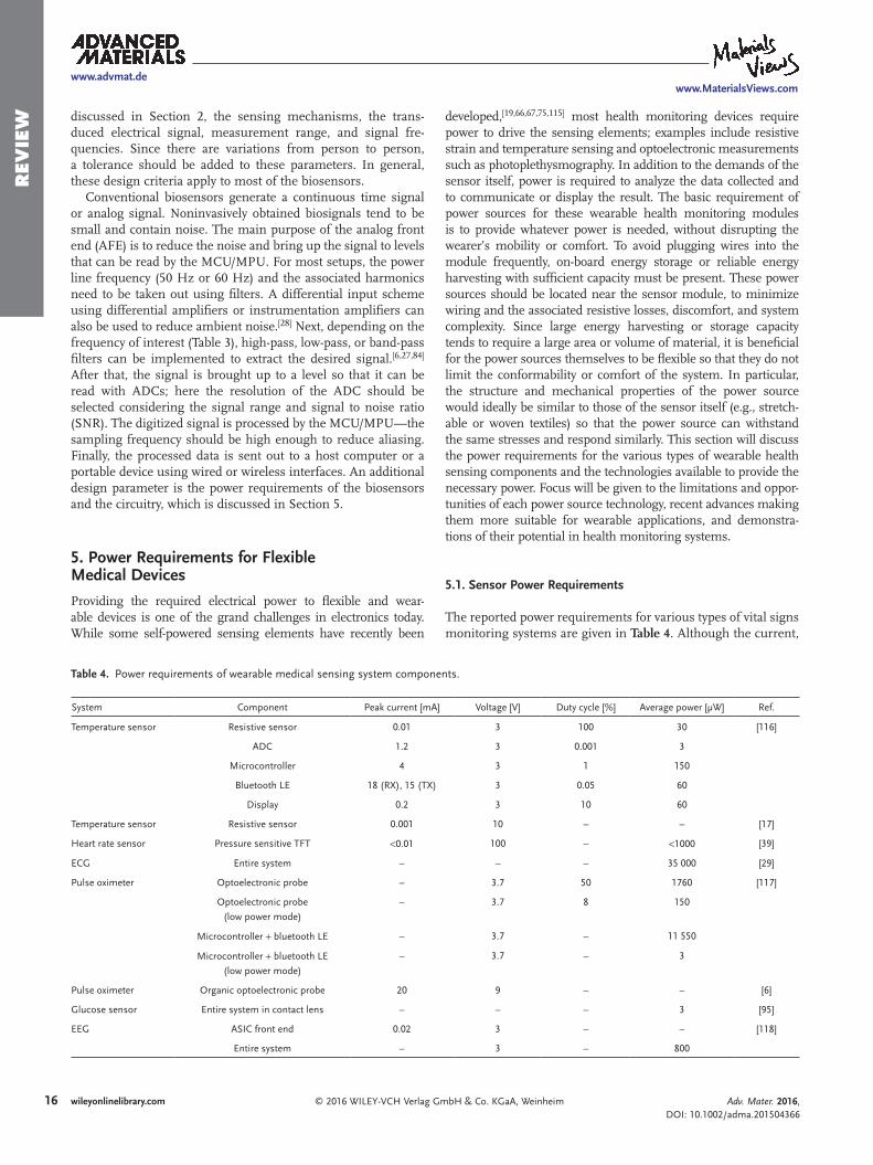
The reported power requirements for various types of vital signs monitoring systems are given in Table 4. Although the current,
Adv. Mater. 2016, DOI: 10.1002/adma.201504366
www.advmat.dewww.MaterialsViews.com
Table 4. Power requirements of wearable medical sensing system components.
System Component Peak current [mA] Voltage [V] Duty cycle [%] Average power [μW] Ref.
Temperature sensor Resistive sensor 0.01 3 100 30 [116]
ADC 1.2 3 0.001 3
Microcontroller 4 3 1 150
Bluetooth LE 18 (RX), 15 (TX) 3 0.05 60
Display 0.2 3 10 60
Temperature sensor Resistive sensor 0.001 10 – – [17]
Heart rate sensor Pressure sensitive TFT <0.01 100 – <1000 [39]
ECG Entire system – – – 35 000 [29]
Pulse oximeter Optoelectronic probe – 3.7 50 1760 [117]
Optoelectronic probe
(low power mode)
– 3.7 8 150
Microcontroller + bluetooth LE – 3.7 – 11 550
Microcontroller + bluetooth LE
(low power mode)
– 3.7 – 3
Pulse oximeter Organic optoelectronic probe 20 9 – – [6]
Glucose sensor Entire system in contact lens – – – 3 [95]
EEG ASIC front end 0.02 3 – – [118]
Entire system – 3 – 800

17wileyonlinelibrary.com© 2016 WILEY-VCH Verlag GmbH & Co. KGaA, Weinheim
Rev
iew
voltage, and power consumption values vary greatly, there are some generalizations to be made. First, the power consumption of light-emitting devices (e.g., the optoelectronic probes used for photoplethysmography) is relatively high compared to resis-tive sensors. The peak current for wireless communication is also very high, although communicating data infrequently can reduce the average power consumption. Microcontrollers con-sume less power than wireless transmitters while operating, but must generally operate for longer time periods, particularly if significant computation is being done locally to avoid sending large amounts of data wirelessly.
Often, the duty cycle of the components can be adjusted to reduce power consumption, either by reducing the operating time of the component during each cycle or by increasing the time between uses of the component. For example, in their design of a solar-powered pulse oximeter, Dieffenderfer et al. included a low-power mode with lower duty cycle for cases when sufficient solar power is not available.[117] However, since monitoring health is of utmost importance, the duty cycle must be adjusted with care to ensure that the reliability of the sensing, data analysis, or communication is not compromised. Also, although reducing the duty cycle reduces the average power, the peak current is typically not impacted. The power supply must therefore be designed to supply the peak current without a sig-nificant loss in efficiency, as well as supplying the average power for whatever duration is required between charging cycles.
Designing custom low-power data-processing circuits and wireless transmitters can also reduce power consumption, such as in the 3 μW glucose-sensing contact lens.[95] However, if a higher power is permissible, use of off-the-shelf compo-nents such as microcontrollers and radios can reduce cost and improve simplicity of the design and compatibility with legacy systems. Additionally, it is desirable to operate all components of a system at the same voltage to avoid additional circuitry to convert between voltages. This is typically in the 3–4 V range, as shown in the table, which is compatible with CMOS circuits and lithium-ion batteries. However, in the case of many thin-film and organic active electronic devices, particularly thin-film transistors such as the pressure sensitive transistors for heart rate monitoring,[39] the voltage requirement can be much greater than that of CMOS circuits. Some types of energy har-vesters also produce voltages that are far outside this range or highly variable. In these cases, power electronics are necessary.
In some sensing mechanisms, a voltage or current is directly generated in response to a stimulus, allowing the sensor to be self-powered. Examples of self-powered sensors are the piezo-electric respiration and heart rate sensors,[66,75] triboelectric respiration and heart rate sensors,[67,115] and thermoelectric temperature sensors.[19] However, since requirements for data processing and communication are significant, a system with a self-powered sensing element is not necessarily able to be fully self-powered.
5.2. Power Sources
If a device is disposable or the user can tolerate replacing the battery, a primary (nonrechargeable) battery can be used as the power source. Primary batteries are used widely in
wearable devices such as watches and hearing aids today. Although the standard coin cell used in these devices is bulky and noncompliant, flexible and stretchable primary batteries have been developed as power sources for flexible electronics.[111,119–121] There is not currently a standard for user-replaceable flexible primary batteries, however. Thus, if the lifetime of a flexible medical device must outlast that of an appropriately sized primary battery, a rechargeable battery is preferable. There has been a great effort toward flexible and stretchable batteries for wearable and flexible electronics applications, which has been the subject of several recent reviews.[116,122–126] Lithium-ion chemistry is considered espe-cially promising for portable and flexible electronics because of its high energy density, power density, and lifetime.[122,127] Alkaline chemistries, such as silver-zinc and zinc-manganese, however, are less toxic and less reactive, allowing them to be fabricated in air and placing less stringent requirements on the encapsulation.[128] Flexible and stretchable batteries have been achieved by various means: depositing the active layers on flex-ible and stretchable substrates such as textile electrodes,[129,130] nonwoven fibrous membranes,[108] and temporary tattoo paper;[128] connecting rigid microbatteries on a stretchable substrate with stretchable serpentine interconnects;[131] using kirigami (cutting and folding) techniques;[132] and fabricating the batteries in the shape of a wire or cable.[133,134] Figure 13 shows a textile-based battery integrated into a shirt and watch-band (a)[130] and a temporary tattoo battery adhered to the skin (b-c).[128] Supercapacitors have also been produced in flexible forms,[135,136] including textiles.[137–139] Supercapacitors charge and discharge much more quickly than batteries, making them unsuitable for long-term energy storage but ideal for providing relatively large amounts of energy over a short time. For sys-tems with a high peak current but a low duty cycle, e.g., low-power systems with occasional wireless communication, a supercapacitor can provide the required burst of power more effectively than a battery. In these systems, a battery and super-capacitor can be used together to ensure both long-term energy demands and short-term peak current demands are met.[116]
The batteries in most consumer electronic products today are charged by connecting wires to a stationary power source such as a wall outlet. For wearable medical sensors, where the user’s health depends on the availability of power for the sensor, the user should not be relied on to plug in the devices, particularly since plugging in many devices can be inconvenient. Therefore, it is important to integrate energy collecting devices into the system. Energy can be collected from ambient light via photo-voltaics (PV) or radio-frequency (RF) electromagnetic waves via antennas. The human body itself is also a source of several types of energy, including thermal, mechanical, and biochem-ical, which can be harvested to power wearable sensors. Table 5 briefly summarizes the available power in each energy source.
The amount of available light energy varies by several orders of magnitude from outdoors on a sunny day to a dim room. However, even in many indoor environments it can be one of the largest sources of energy, as shown in Table 5. So, if cou-pled with a battery large enough to compensate for the daily variation in light intensity experienced by most people, PV can be a very useful energy source. There have therefore been multiple recent demonstrations of commercial photovoltaic
Adv. Mater. 2016, DOI: 10.1002/adma.201504366
www.advmat.dewww.MaterialsViews.com
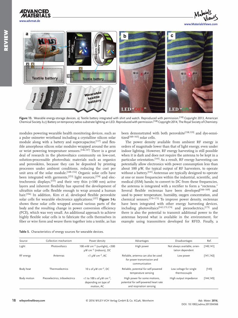
18 wileyonlinelibrary.com © 2016 WILEY-VCH Verlag GmbH & Co. KGaA, Weinheim
Rev
iew
modules powering wearable health monitoring devices, such as a pulse oximeter wristband including a crystalline silicon solar module along with a battery and supercapacitor,[117] and flex-ible amorphous silicon solar modules wrapped around the arm or wrist powering temperature sensors.[146,147] There is a great deal of research in the photovoltaics community on low-cost, solution-processable photovoltaic materials such as organics and perovskites, because they can be deposited by printing processes under ambient conditions, reducing the cost per unit area of the solar module.[148–152] Organic solar cells have been integrated with garments,[153] light sources,[154] and elec-trochromic displays,[155] and their very thin (≈100 nm) active layers and inherent flexibility has spurred the development of ultrathin solar cells flexible enough to wrap around a human hair.[156] In addition, Kim et al. developed flexible perovskite solar cells for wearable electronics applications.[157] Figure 14a shows these solar cells wrapped around various parts of the body and the resulting change in power conversion efficiency (PCE), which was very small. An additional approach to achieve highly flexible solar cells is to fabricate the cells themselves in fiber or wire form and weave them together into a textile, as has
been demonstrated with both perovskite[158,159] and dye-sensi-tized[160–163] solar cells.
The power density available from ambient RF energy is orders of magnitude lower than that of light energy, even under indoor lighting. However, RF energy harvesting is still possible when it is dark and does not require the antenna to be kept in a particular orientation.[141] As a result, RF energy harvesting can potentially allow electronics with power consumption less than about 100 μW, the typical output of RF harvesters, to operate without a battery.[141] Antennas are typically designed to operate at one or more frequencies within the industrial, scientific, and medical (ISM) bands; to convert to DC from these frequencies, the antenna is integrated with a rectifier to form a “rectenna.” Several flexible rectennas have been developed[166–169] and used to power temperature, humidity, oxygen concentration, and chemical sensors.[170–172] To improve power density, rectennas have been integrated with other energy harvesting devices, including photovoltaics[142,173,174] and piezoelectrics,[175] and there is also the potential to transmit additional power to the antennas beyond what is available in the environment, for example using transmitters developed for RFID. Finally, a
Adv. Mater. 2016, DOI: 10.1002/adma.201504366
www.advmat.dewww.MaterialsViews.com
Table 5. Characteristics of energy sources for wearable devices.
Source Collection mechanism Power density Advantages Disadvantages Ref.
Light Photovoltaics 100 mW cm−2 (sunlight), <500
μW cm−2 (indoors), DC
High power Not always available, orien-
tation dependent
[140,141]
RF energy Antennas <1 μW cm−2, AC Reliable, antenna can also be used
for power transmission and
communication
Low power [141,142]
Body heat Thermoelectrics 10 s of μW cm−2, DC Reliable, potential for self-powered
temperature sensing
Low voltage for single
thermocouple
[143]
Body motion Piezoelectrics, triboelectrics <1 to 100 s of μW cm−2,
depending on type of
motion, AC
High power for some motions,
potential for self-powered heart rate
and respiration sensing
High output impedance [144,145]
Figure 13. Wearable energy-storage devices. a) Textile battery integrated with shirt and watch. Reproduced with permission.[130] Copyright 2013, American Chemical Society. b,c) Battery on temporary tattoo substrate lighting an LED. Reproduced with permission.[128] Copyright 2014, The Royal Society of Chemistry.

19wileyonlinelibrary.com© 2016 WILEY-VCH Verlag GmbH & Co. KGaA, Weinheim
Rev
iew
Adv. Mater. 2016, DOI: 10.1002/adma.201504366
www.advmat.dewww.MaterialsViews.com
single antenna can perform multiple functions that are impor-tant for medical devices: receiving energy, transmitting excess energy to another device that is energy-starved, and sending and receiving data.[142,176]
Another reliable energy source for wearable medical devices is the heat of the body itself, which can be converted to elec-tricity using thermoelectric generators attached to the skin. While the state-of-the-art thermoelectric generators rely on rigid, brittle, and expensive Bi2Te3 and Sb2Te3-based inorganic materials, there has been a great deal of effort recently toward flexible and lower-cost thermoelectric generators.[143] This has been accomplished by printing[164,177–179] or sputtering[180] films of the Bi2Te3 and Sb2Te3 materials on flexible substrates, infil-trating the films with PEDOT:PSS to improve flexibility,[181] and employing alternative materials with higher flexibility such as carbon nanotubes,[182,183] PEDOT:PSS,[184,185] and Te nanorods.[186] Figure 14b–c shows the flexible Bi2Te3/Sb2Te3 thermoelectric generator on a glass fabric developed by Kim et al. (Figure 14b), generating electricity from the heat of a person’s wrist (Figure 14c).[164] The voltage of a thermoelectric generator is proportional to the temperature difference, and the power output is proportional to the square of the temperature differ-ence. Thus, to maximize power output, the generator should be subjected to the entire temperature difference between the body and the surroundings, requiring good thermal contact with the body on one side and good cooling on the other (ambient) side. Still, the difference between body temperature and air tempera-ture is relatively small, giving millivolt-level voltages for a single generator.[164,178,181,186] The 1 V or greater voltage levels required by most electronics are thus achieved by connecting dozens of thermoelectric generators in series[143,182] or by using power electronics to boost the voltage.[118,187] Nevertheless, wearable thermoelectric generators have been used to power a number of medical sensing devices including a glucose sensor,[182] pulse oximeter,[187] and electroencephalogram.[118]
The various motions of the human body, including foot-steps, motion of limbs, flexing of muscles, and breathing, are also sources of energy that can be used to power sen-sors. The energy available in these motions, which varies over several orders of magnitude as indicated in Table 5, can be harvested using wearable piezoelectric or triboelectric genera-tors. Piezoelectric materials generate electricity in response to a pressure signal; most common among them is the high-performing but brittle piezoelectric material lead zirconate titanate (PZT).[188] Flexible piezoelectric nanogenerators have recently been developed based on more flexible forms of PZT such as thin ribbons[189] or nanowires,[190] as well as lead-free materials such as PVDF,[145,165,191–193] ZnO nanowires,[194] and cellular polypropylene.[75] Triboelectric generators, on the other hand, generate electricity from the transfer of surface charge that occurs when certain materials, including many common metals and polymers, are brought into contact,[144] either by pressing and releasing[195] or sliding.[196] Piezoelec-tric and triboelectric sensors have been used to harvest energy from the motion of joints such as wrists, fingers, elbows, and knees.[115,145,165,192,194] Figure 14d shows a piezoelectric gen-erator developed by Siddiqui et al. on the finger, wrist, and elbow, and the corresponding voltage waveforms as each of those joints are bent.[165] Figure 14e shows photographs and voltage waveforms for a triboelectric generator by Yang et al. on the elbow and bicep.[115] Since footsteps are a relatively large source of energy among body motions, piezoelectrics have been integrated into shoes and demonstrated an average power generation of around 1 mW during walking or run-ning.[145,191] Triboelectric generators have also been integrated into textiles to harvest energy from the sliding motion of the arm past the side of the body.[197–199] Pu et al. showed the promise of these triboelectric generators for wearable elec-tronics by integrating one with a textile lithium-ion battery and powering a heartbeat meter.[198]
Figure 14. Wearable energy-harvesting devices. a) Flexible perovskite solar cells on different parts of the body, and effect of curvature radius on power conversion efficiency (PCE). Reproduced with permission.[157] Copyright 2015, The Royal Society of Chemistry. b,c) Flexible thermoelectric generator on a glass fabric substrate. Reproduced with permission.[164] Copyright 2014, The Royal Society of Chemistry. d,e) Devices to harvest energy from body motion. d) Piezoelectric generator on the knuckle, wrist, and elbow, and corresponding voltage output as the joint is flexed. Reproduced with permis-sion.[165] Copyright 2015, Elsevier. e) Triboelectric generator on the elbow and bicep, and corresponding voltage output during flexing. Reproduced with permission.[115] Copyright 2015, Wiley-VCH.

20 wileyonlinelibrary.com © 2016 WILEY-VCH Verlag GmbH & Co. KGaA, Weinheim
Rev
iew
Adv. Mater. 2016, DOI: 10.1002/adma.201504366
www.advmat.dewww.MaterialsViews.com
Finally, biochemical energy can be extracted to power wear-able devices using biofuel cells. For example, lactate in sweat was oxidized in a textile wristband or headband to generate electricity.[200] Sensors embedded in contact lenses can espe-cially benefit from this type of energy since it is particularly difficult to make connections to external power supplies. Con-tact-lens-based biofuel cells have therefore been developed that utilize the glucose[201] and ascorbate[202] present in tears as fuel.
Challenges still remain for the integration of these various power sources with medical devices. First, the power source should be near the location of the biosignal to be monitored, as well as in a place with sufficient energy to be collected, to minimize wiring. Second, the materials of the power source must be safe and nontoxic. If power electronics are required, they must use small components, flexible whenever possible, to maximize comfort. In some cases, multiple types of power sources may be integrated together to meet the demands of the sensors. Nevertheless, the amounts of available power in many forms and the many advances toward wearable power sources should allow the development of medical devices with reliable, on-board power supplies and little or no wired charging.
6. Conclusion
In conclusion, a plethora of flexible and wearable medical devices have been demonstrated with applications in vital signs monitoring, electronic skin, and epidermal and implantable medical sensing. Most of the reported devices utilize flexible, stretchable, and lightweight materials for fabricating the bio-sensors. The data processing and transmission requirements were met using silicon-based electronics. This scheme allowed the best use of both soft and hard electronics. In this review paper, we listed and discussed flexible and wearable vital-signs monitoring devices, focusing on biosignals such as tempera-ture, heart rate, respiration rate, blood pressure, pulse oxygena-tion, and blood glucose. We hope that this review will provide readers with the underlying sensing principle, sensor fabrica-tion, data processing, and power requirements of these novel biosensors. We also hope this review will convince readers that with further improvement of the biosensors coupled with low-cost and large-area processing capabilities, the promise of soft bioelectronic and biophotonic sensors and its applications in monitoring vital signs is enormous.
AcknowledgmentsAll the authors contributed equally to this review. This work is partially supported by the National Science Foundation under Grant No. EFRI 1240380. This work is also supported in part by Systems on Nanoscale Information fabriCs (SONIC), one of the six SRC STARnet Centers, sponsored by MARCO and DARPA. The authors thank Dr. Abhinav Gaikwad, Dr. Balthazar Lechêne, Dr. Anita Flynn, Dr. Donggeon Han, Dr. Igal Deckman, and Alla Zamarayeva for numerous helpful discussions. A.O., C.M.L., and A.P. wish to acknowledge financial support from the NSF Graduate Fellowship Research Program under Grant No. DGE-1106400.
Received: September 6, 2015Revised: October 9, 2015
Published online:
[1] K. Tillmann, Understanding the Connected Health and Wellness Market, Technical Report, Consumer Electronics Association, 2014.
[2] J. Kim, M. Lee, H. J. Shim, R. Ghaffari, H. R. Cho, D. Son, Y. H. Jung, M. Soh, C. Choi, S. Jung, K. Chu, D. Jeon, S. T. Lee, J. H. Kim, S. H. Choi, T. Hyeon, D. H. Kim,Nat. Commun. 2014, 5, 5747.
[3] J. C. Barrese, N. Rao, K. Paroo, C. Triebwasser, C. Vargas-Irwin, L. Franquemont, J. P. Donoghue, J. Neural Eng. 2013, 10, 066014.
[4] N. Matsuhisa, M. Kaltenbrunner, T. Yokota, H. Jinno, K. Kuribara, T. Sekitani, T. Someya, Nat. Commun. 2015, 6, 7461.
[5] T. Sekitani, H. Nakajima, H. Maeda, T. Fukushima, T. Aida, K. Hata, T. Someya, Nat. Mater. 2009, 8, 494.
[6] C. M. Lochner, Y. Khan, A. Pierre, A. C. Arias, Nat. Commun. 2014, 5, 5745.
[7] S. L. Swisher, M. C. Lin, A. Liao, E. J. Leeflang, Y. Khan, F. J. Pavinatto, K. Mann, A. Naujokas, D. Young, S. Roy, M. R. Harrison, A. C. Arias, V. Subramanian, M. M. Maharbiz, Nat. Commun. 2015, 6, 6575.
[8] J. Kim, A. Banks, H. Cheng, Z. Xie, S. Xu, K.-I. Jang, J. W. Lee, Z. Liu, P. Gutruf, X. Huang, P. Wei, F. Liu, K. Li, M. Dalal, R. Ghaffari, X. Feng, Y. Huang, S. Gupta, U. Paik, J. A. Rogers, Small 2015, 11, 906.
[9] D.-H. Kim, N. Lu, R. Ghaffari, Y.-S. Kim, S. P. Lee, L. Xu, J. Wu, R.-H. Kim, J. Song, Z. Liu, J. Viventi, B. de Graff, B. Elolampi, M. Mansour, M. J. Slepian, S. Hwang, J. D. Moss, S.-M. Won, Y. Huang, B. Litt, J. A. Rogers, Nat. Mater. 2011, 10, 316.
[10] Medical Device, Technical Report, US Food and Drug Administra-tion, 2015, http://www.fda.gov/aboutfda/transparency/basics/ucm211822.htm, accessed: August, 2015.
[11] D. Evans, B. Hodgkinson, J. Berry, Int. J. Nurs. Stud. 2001, 38, 643.[12] Y. Makino, S. Ogawa, H. Shinoda, in SICE Annual Conf., 2008,
IEEE, 2008, pp. 1468–1473.[13] X. Zhang, X. Chen, W.-H. Wang, J.-H. Yang, V. Lantz, K.-Q. Wang,
in Proc. of the 14th Int. Conf. on Intelligent User Interfaces, ACM, 2009, pp. 401–406.
[14] B. W. Olesen, Tech. Rev. 1982, 2, 3.[15] A. Giuliani, M. Placidi, F. Di Francesco, A. Pucci, React. Funct.
Polym. 2014, 76, 57.[16] W. Honda, S. Harada, T. Arie, S. Akita, K. Takei, Adv. Funct. Mater.
2014, 24, 3299.[17] C. Yan, J. Wang, P. S. Lee, ACS Nano 2015, 9, 2130.[18] C.-C. Huang, Z.-K. Kao, Y.-C. Liao, ACS Appl. Mater. Interfaces
2013, 5, 12954.[19] Y. Yang, Z.-H. Lin, T. Hou, F. Zhang, Z. L. Wang, Nano Res. 2012,
5, 888.[20] W. Wu, J. Shen, P. Banerjee, S. Zhou, Biomaterials 2010, 31, 7555.[21] J. Jeon, H.-B.-R. Lee, Z. Bao, Adv. Mater. 2013, 25, 850.[22] C. A. Boano, M. Lasagni, K. Romer, T. Lange, in 14th IEEE Int.
Symposium on Object/Component/Service-Oriented Real-Time Dis-tributed Computing Workshops (ISORCW), 2011, IEEE, 2011, pp. 189–198.
[23] R. Lenhardt, D. I. Sessler, Anesthesiology 2006, 105, 1117.[24] M. V. Savage, G. L. Brengelmann, J. Appl. Physiol. 1996, 80, 1249.[25] V. L. Richmond, S. Davey, K. Griggs, G. Havenith, Ann. Occup.
Hyg. 2015, 59, 1168.[26] X. Xu, A. J. Karis, M. J. Buller, W. R. Santee, Eur. J. Appl. Physiol.
2013, 113, 2381.[27] E. Nemati, M. J. Deen, T. Mondal, IEEE Commun. Mag. 2012, 50, 36.[28] S. E. Derenzo, Practical Interfacing in the Laboratory: Using a PC for
Instrumentation, Data Analysis and Control, Cambridge University Press, Cambridge, UK 2003.
[29] S. Xu, Y. Zhang, L. Jia, K. E. Mathewson, K.-I. Jang, J. Kim, H. Fu, X. Huang, P. Chava, R. Wang, S. Bhole, L. Wang, Y. J. Na, Y. Guan, M. Flavin, Z. Han, Y. Huang, J. A. Rogers, Science 2014, 344, 70.
[10] http://www.fda.gov/aboutfda/transparency/basics/ucm211822.htm
Please update hyperlink.
21wileyonlinelibrary.com© 2016 WILEY-VCH Verlag GmbH & Co. KGaA, Weinheim
Rev
iew
Adv. Mater. 2016, DOI: 10.1002/adma.201504366
www.advmat.dewww.MaterialsViews.com
[30] J.-Y. Baek, J.-H. An, J.-M. Choi, K.-S. Park, S.-H. Lee, Sens. Actuators, A 2008, 143, 423.
[31] H.-C. Jung, J.-H. Moon, D.-H. Baek, J.-H. Lee, Y.-Y. Choi, J.-S. Hong, S.-H. Lee, IEEE Trans. Biomed. Eng. 2012, 59, 1472.
[32] G. S. Jeong, D.-H. Baek, H. C. Jung, J. H. Song, J. H. Moon, S. W. Hong, I. Y. Kim, S.-H. Lee, Nat. Commun. 2012, 3, 977.
[33] P. Shyamkumar, P. Rai, S. Oh, M. Ramasamy, R. E. Harbaugh, V. Varadan, Electronics 2014, 3, 504.
[34] J. Yoo, L. Yan, S. Lee, H. Kim, H.-J. Yoo, IEEE Trans. Inf. Technol. Biomed. 2009, 13, 897.
[35] Y. M. Chi, T.-P. Jung, G. Cauwenberghs, IEEE Rev. Biomed. Eng. 2010, 3, 106.
[36] A. I. Ianov, H. Kawamoto, Y. Sankai, in ICME Int. Conf. on Complex Medical Engineering (CME), IEEE, 2012, pp. 593–598.
[37] Y. M. Chi, S. R. Deiss, G. Cauwenberghs, in Sixth International Workshop on Wearable and Implantable Body Sensor Networks, 2009 (BSN 2009), IEEE, 2009, pp. 246–250.
[38] P. Leleux, C. Johnson, X. Strakosas, J. Rivnay, T. Hervé, R. M. Owens, G. G. Malliaras, Adv. Healthcare Mater. 2014, 3, 1377.
[39] G. Schwartz, B. C.-K. Tee, J. Mei, A. L. Appleton, D. H. Kim, H. Wang, Z. Bao, Nat. Commun. 2013, 4, 1859.
[40] B. Nie, S. Xing, J. D. Brandt, T. Pan, Lab Chip 2012, 12, 1110.[41] L. Guo, L. Berglin, U. Wiklund, H. Mattila, Text. Res. J. 2012, 83, 499.[42] S. D. Min, Y. Yun, H. Shin, IEEE Sensors J. 2014, 14, 3245.[43] O. Atalay, W. R. Kennon, E. Demirok, IEEE Sensors J. 2015, 15, 110.[44] R. D. Allison, E. L. Holmes, J. Nyboer, J. Appl. Physiol. 1964, 19, 166.[45] M. Folke, L. Cernerud, M. Ekström, B. Hök, Med. Biol. Eng.
Comput. 2003, 41, 377.[46] F. Q. Al-Khalidi, R. Saatchi, D. Burke, H. Elphick, S. Tan, Pediatr.
Pulmonol. 2011, 46, 523.[47] P. Corbishley, E. Rodriguez-Villegas, IEEE Trans. Biomed. Eng.
2008, 55, 196.[48] O. Mimoz, T. Benard, A. Gaucher, D. Frasca, B. Debaene, Brit.
J. Anaesth. 2012, 108, 872.[49] K. P. Cohen, W. M. Ladd, D. M. Beams, W. S. Sheers,
R. G. Radwin, W. J. Tompkins, J. G. Webster, IEEE Trans. Biomed. Eng. 1997, 44, 555.
[50] C. Merritt, H. Nagle, E. Grant, IEEE Sensors J. 2009, 9, 71.[51] G. K. Prisk, J. Hammer, C. J. L. Newth, Pediatr. Pulmonol. 2002,
34, 462.[52] C.-T. Huang, C.-L. Shen, C.-F. Tang, S.-H. Chang, Sens. Actuators,
A 2008, 141, 396.[53] R. Wijesiriwardana, IEEE Sensors J. 2006, 6, 571.[54] T. Hoffmann, B. Eilebrecht, S. Leonhardt, IEEE Sensors J. 2011, 11,
1112.[55] Y. Li, Y. A. Samad, K. Liao, J. Mater. Chem. A 2015, 3, 2181.[56] S. K. Kundu, S. Kumagai, M. Sasaki, Jpn. J. Appl. Phys. 2013, 52,
04CL05.[57] E. Laukhina, R. Pfattner, L. R. Ferreras, S. Galli, M. Mas-Torrent,
N. Masciocchi, V. Laukhin, C. Rovira, J. Veciana, Adv. Mater. 2009, 22, 977.
[58] T. Allsop, K. Carroll, G. Lloyd, D. J. Webb, M. Miller, I. Bennion, J. Biomed. Opt. 2007, 12, 064003.
[59] A. Grillet, D. Kinet, J. Witt, M. Schukar, K. Krebber, F. Pirotte, A. Depre, IEEE Sensors J. 2008, 8, 1215.
[60] W. Zheng, X. Tao, B. Zhu, G. Wang, C. Hui, Text. Res. J. 2014, 84, 1791.
[61] T. Yamada, Y. Hayamizu, Y. Yamamoto, Y. Yomogida, A. Izadi-Najafabadi, D. N. Futaba, K. Hata, Nat. Nanotechnol. 2011, 6, 296.
[62] Y. Wang, L. Wang, T. Yang, X. Li, X. Zang, M. Zhu, K. Wang, D. Wu, H. Zhu, Adv. Funct. Mater. 2014, 24, 4666.
[63] C. S. Boland, U. Khan, C. Backes, A. O’Neill, J. McCauley, S. Duane, R. Shanker, Y. Liu, I. Jurewicz, A. B. Dalton, J. N. Coleman, ACS Nano 2014, 8, 8819.
[64] L. Cai, L. Song, P. Luan, Q. Zhang, N. Zhang, Q. Gao, D. Zhao, X. Zhang, M. Tu, F. Yang, W. Zhou, Q. Fan, J. Luo, W. Zhou, P. M. Ajayan, S. Xie, Sci. Rep. 2013, 3, 3048.
[65] S. Rajala, J. Lekkala, IEEE Sensors J. 2012, 12, 439.[66] Y.-Y. Chiu, W.-Y. Lin, H.-Y. Wang, S.-B. Huang, M.-H. Wu, Sens.
Actuators, A 2013, 189, 328.[67] F. Yi, L. Lin, S. Niu, P. K. Yang, Z. Wang, J. Chen, Y. Zhou, Y. Zi,
J. Wang, Q. Liao, Y. Zhang, Z. L. Wang, Adv. Funct. Mater. 2015, 25, 3688.
[68] B. M. Quandt, L. J. Scherer, L. F. Boesel, M. Wolf, G.-L. Bona, R. M. Rossi, Adv. Healthcare Mater. 2015, 4, 330.
[69] A. P. Avolio, M. Butlin, A. Walsh, Physiol. Meas. 2010, 31, R1.[70] C. Dagdeviren, Y. Su, P. Joe, R. Yona, Y. Liu, Y.-S. Kim, Y. Huang,
A. R. Damadoran, J. Xia, L. W. Martin, Y. Huang, J. A. Rogers, Nat. Commun. 2014, 5, 4496.
[71] R. Li, B. Nie, P. Digiglio, T. Pan, Adv. Funct. Mater. 2014, 24, 6195.[72] Z. Li, Z. L. Wang, Adv. Mater. 2011, 23, 84.[73] X. Wang, Y. Gu, Z. Xiong, Z. Cui, T. Zhang, Adv. Mater. 2014, 26,
1336.[74] C.-L. Choong, M.-B. Shim, B.-S. Lee, S. Jeon, D.-S. Ko, T.-H. Kang,
J. Bae, S. H. Lee, K.-E. Byun, J. Im, Y. J. Jeong, C. E. Park, J.-J. Park, U.-I. Chung, Adv. Mater. 2014, 26, 3451.
[75] N. Wu, X. Cheng, Q. Zhong, J. Zhong, W. Li, B. Wang, B. Hu, J. Zhou, Adv. Funct. Mater. 2015, 25, 4788.
[76] S. Terry, J. Eckerle, R. Kornbluh, T. Low, C. Ablow, Sens. Actuators, A 1990, 23, 1070.
[77] T. Someya, T. Sekitani, S. Iba, Y. Kato, H. Kawaguchi, T. Sakurai, Proc. Natl. Acad. Sci. USA 2004, 101, 9966.
[78] K.-H. Shin, C.-R. Moon, T.-H. Lee, C.-H. Lim, Y.-J. Kim, Sens. Actuators, A 2005, 123, 30.
[79] S. C. Mannsfeld, B. C. Tee, R. M. Stoltenberg, C. V. H. Chen, S. Barman, B. V. Muir, A. N. Sokolov, C. Reese, Z. Bao, Nat. Mater. 2010, 9, 859.
[80] B. C.-K. Tee, A. Chortos, R. R. Dunn, G. Schwartz, E. Eason, Z. Bao, Adv. Funct. Mater. 2014, 24, 5427.
[81] S. Park, H. Kim, M. Vosgueritchian, S. Cheon, H. Kim, J. H. Koo, T. R. Kim, S. Lee, G. Schwartz, H. Chang, Z. Bao, Adv. Mater. 2014, 26, 7324.
[82] M. K. Choi, O. K. Park, C. Choi, S. Qiao, R. Ghaffari, J. Kim, D. J. Lee, M. Kim, W. Hyun, S. J. Kim, H. J. Hwang, S.-H. Kwon, T. Hyeon, N. Lu, D.-H. Kim, Adv. Healthcare Mater. 2016, 5, 80.
[83] J. G. Webster, Design of Pulse Oximeters, Taylor and Francis, New York, 1997.
[84] Y. Khan, C. M. Lochner, A. Pierre, A. C. Arias, in 6th IEEE Inter-national Workshop on Advances in Sensors and Interfaces (IWASI), IEEE, 2015, pp. 83–86.
[85] A. K. Bansal, S. Hou, O. Kulyk, E. M. Bowman, I. D. W. Samuel, Adv. Mater. 2014, 27, 7638.
[86] M. Rothmaier, B. Selm, S. Spichtig, D. Haensse, M. Wolf, Opt. Express 2008, 16, 12973.
[87] Global Status Report on Noncommunicable Diseases, Technical Report, World Health Organization, 2014, http://www.who.int/global-coordination-mechanism/publications/global-status-report-ncds-2014-eng.pdf?ua=1, accessed: August, 2015.
[88] S. Iguchi, H. Kudo, T. Saito, M. Ogawa, H. Saito, K. Otsuka, A. Funakubo, K. Mitsubayashi, Biomed. Microdevices 2007, 9, 603.
[89] M.-C. Chuang, Y.-L. Yang, T.-F. Tseng, T. Chou, S.-L. Lou, J. Wang, Talanta 2010, 81, 15.
[90] H. Kudo, T. Sawada, E. Kazawa, H. Yoshida, Y. Iwasaki, K. Mitsubayashi, Biosens. Bioelectron. 2006, 22, 558.
[91] X. You, J. J. Pak, Sens. Actuators, B 2014, 202, 1357.[92] Y. H. Kwak, D. S. Choi, Y. N. Kim, H. Kim, D. H. Yoon, S.-S. Ahn,
J.-W. Yang, W. S. Yang, S. Seo, Biosens. Bioelectron. 2012, 37, 82.[93] A. J. Bandodkar, W. Jia, C. Yardımcı, X. Wang, J. Ramirez, J. Wang,
Anal. Chem. 2014, 87, 394.
22 wileyonlinelibrary.com © 2016 WILEY-VCH Verlag GmbH & Co. KGaA, Weinheim
Rev
iew
Adv. Mater. 2016, DOI: 10.1002/adma.201504366
www.advmat.dewww.MaterialsViews.com
[94] Y.-T. Liao, H. Yao, A. Lingley, B. Parviz, B. Otis, IEEE J. Solid-State Circuits 2012, 47, 335.
[95] Y.-T. Liao, H. Yao, B. Parviz, B. Otis, in IEEE International Solid-State Circuits Conference, Digest of Technical Papers (ISSCC), 2011, IEEE, 2011, pp. 38–40.
[96] A. C. Arias, J. D. MacKenzie, I. McCulloch, J. Rivnay, A. Salleo, Chem. Rev. 2010, 110, 3.
[97] H. C. Ko, M. P. Stoykovich, J. Song, V. Malyarchuk, W. M. Choi, C.-J. Yu, J. B. Geddes Iii, J. Xiao, S. Wang, Y. Huang, J. A. Rogers, Nature 2008, 454, 748.
[98] J. Viventi, D.-H. Kim, J. D. Moss, Y.-S. Kim, J. A. Blanco, N. Annetta, A. Hicks, J. Xiao, Y. Huang, D. J. Callans, J. A. Rogers, B. Litt, Sci. Transl. Med. 2010, 2, 24ra22.
[99] M. B. Akin, A. C. Arias, A Comprehensive Surface Mount Technology Solution for Integrated Circuits onto Flexible Screen Printed Electrical Interconnects, Technical report, DTIC Document, 2014.
[100] A. Pierre, M. Sadeghi, M. M. Payne, A. Facchetti, J. E. Anthony, A. C. Arias, Adv. Mater. 2014, 26, 5722.
[101] F. C. Krebs, Sol. Energy Mater. Sol. Cells 2009, 93, 394.[102] H. Kang, R. Kitsomboonloha, K. Ulmer, L. Stecker, G. Grau,
J. Jang, V. Subramanian, Org. Electron. 2014, 15, 3639.[103] A. Pierre, I. Deckman, P. B. Lechêne, A. C. Arias, Adv. Mater. 2015,
27, 41, 6411.[104] M. D. Fagan, B. H. Kim, D. Yao, Adv. Polym. Technol. 2009, 28,
246.[105] N. Komuro, S. Takaki, K. Suzuki, D. Citterio, Anal. Bioanal.Chem.
2013, 405, 5785.[106] W. Jia, A. J. Bandodkar, G. Valdés-Ramírez, J. R. Windmiller,
Z. Yang, J. Ramírez, G. Chan, J. Wang, Anal. Chem. 2013, 85, 6553.
[107] A. J. Bandodkar, D. Molinnus, O. Mirza, T. Guinovart, J. R. Windmiller, G. Valdés-Ramírez, F. J. Andrade, M. J. Schöning, J. Wang, Biosens. Bioelectron. 2014, 54, 603.
[108] A. M. Gaikwad, B. V. Khau, G. Davies, B. Hertzberg, D. A. Steingart, A. C. Arias, Adv. Energy Mater. 2014, 5, 3.
[109] F. J. Pavinatto, C. W. Paschoal, A. C. Arias, Biosens. Bioelectron. 2015, 67, 553.
[110] D. Soltman, B. Smith, H. Kang, S. Morris, V. Subramanian, Langmuir 2010, 26, 15686.
[111] K. Braam, V. Subramanian, Adv. Mater. 2014, 27, 689.[112] A. M. Gaikwad, G. L. Whiting, D. A. Steingart, A. C. Arias, Adv.
Mater. 2011, 23, 3251.[113] A. M. Gaikwad, A. M. Zamarayeva, J. Rousseau, H. Chu, I. Derin,
D. A. Steingart, Adv. Mater. 2012, 24, 5071.[114] J. Webster, Medical Instrumentation: Application and Design, John
Wiley & Sons, Hoboken, NJ, USA, 2010.[115] P.-K. Yang, L. Lin, F. Yi, X. Li, K. C. Pradel, Y. Zi, C.-I. Wu, J.-H. He,
Y. Zhang, Z. L. Wang, Adv. Mater. 2015, 27, 3817.[116] J. D. MacKenzie, C. Ho, Proc. IEEE 2015, 103, 535.[117] J. P. Dieffenderfer, E. Beppler, T. Novak, E. Whitmire,
R. Jayakumar, C. Randall, W. Qu, R. Rajagopalan, A. Bozkurt, in 2014 36th Annual Int. Conf. of the IEEE Engineering in Medicine and Biology Society, IEEE, 2014.
[118] M. Van Bavel, V. Leonov, R. F. Yazicioglu, T. Torfs, C. Van Hoof, N. E. Posthuma, R. J. Vullers, Sens. Transducers J. 2008, 94, 103.
[119] A. M. Gaikwad, A. M. Zamarayeva, J. Rousseau, H. Chu, I. Derin, D. A. Steingart, Adv. Mater. 2012, 24, 5071.
[120] A. M. Gaikwad, H. N. Chu, R. Qeraj, A. M. Zamarayeva, D. A. Steingart, Energy Technol. 2013, 1, 177.
[121] A. M. Gaikwad, D. A. Steingart, T. N. Ng, D. E. Schwartz, G. L. Whiting, Appl. Phys. Lett. 2013, 102, 233302.
[122] H. Gwon, J. Hong, H. Kim, D.-H. Seo, S. Jeon, K. Kang, Energy Environ. Sci. 2014, 7, 538.
[123] Y. Hu, X. Sun, J. Mater. Chem. A 2014, 2, 10712.
[124] X. Wang, X. Lu, B. Liu, D. Chen, Y. Tong, G. Shen, Adv. Mater. 2014, 26, 4763.
[125] G. Zhou, F. Li, H.-M. Cheng, Energy Environ. Sci. 2014, 7, 1307.[126] A. M. Gaikwad, A. C. Arias, D. A. Steingart, Energy Technol. 2015,
3, 305.[127] M. Armand, J.-M. Tarascon, Nature 2008, 451, 652.[128] S. Berchmans, A. J. Bandodkar, W. Jia, J. Ramírez, Y. S. Meng,
J. Wang, J. Mater. Chem. A 2014, 2, 15788.[129] G. Kettlgruber, M. Kaltenbrunner, C. M. Siket, R. Moser,
I. M. Graz, R. Schwödiauer, S. Bauer, J. Mater. Chem. A 2013, 1, 5505.
[130] Y.-H. Lee, J.-S. Kim, J. Noh, I. Lee, H. J. Kim, S. Choi, J. Seo, S. Jeon, T.-S. Kim, J.-Y. Lee, J. W. Choi, Nano Lett. 2013, 13, 5753.
[131] S. Xu, Y. Zhang, J. Cho, J. Lee, X. Huang, L. Jia, J. A. Fan, Y. Su, J. Su, H. Zhang, H. Cheng, B. Lu, C. Yu, C. Chuang, T. il Kim, T. Song, K. Shigeta, S. Kang, C. Dagdeviren, I. Petrov, P. V. Braun, Y. Huang, U. Paik, J. A. Rogers, Nat. Commun. 2013, 4, 1543.
[132] Z. Song, X. Wang, C. Lv, Y. An, M. Liang, T. Ma, D. He, Y.-J. Zheng, S.-Q. Huang, H. Yu, H. Jiang, Sci. Rep. 2015, 5, 10988.
[133] J. Ren, Y. Zhang, W. Bai, X. Chen, Z. Zhang, X. Fang, W. Weng, Y. Wang, H. Peng, Angew. Chem. 2014, 126, 7998.
[134] J. Park, M. Park, G. Nam, J. S. Lee, J. Cho, Adv. Mater. 2014, 27, 1396.
[135] M. F. El-Kady, V. Strong, S. Dubin, R. B. Kaner, Science 2012, 335, 1326.
[136] L. Li, Z. Wu, S. Yuan, X.-B. Zhang, Energy Environ. Sci. 2014, 7, 2101.
[137] J. A. Lee, M. K. Shin, S. H. Kim, H. U. Cho, G. M. Spinks, G. G. Wallace, M. D. Lima, X. Lepró, M. E. Kozlov, R. H. Baughman, S. J. Kim, Nat. Commun. 2013, 4, 1970.
[138] L. Kou, T. Huang, B. Zheng, Y. Han, X. Zhao, K. Gopalsamy, H. Sun, C. Gao, Nat. Commun. 2014, 5, 3754.
[139] L. Liu, Y. Yu, C. Yan, K. Li, Z. Zheng, Nat. Commun. 2015, 6, 7260.[140] L. Roselli, N. B. Carvalho, F. Alimenti, P. Mezzanotte,
G. Orecchini, M. Virili, C. Mariotti, R. Goncalves, P. Pinho, Proc. IEEE 2014, 102, 1723.
[141] S. Kim, R. Vyas, J. Bito, K. Niotaki, A. Collado, A. Georgiadis, M. M. Tentzeris, Proc. IEEE 2014, 102, 1649.
[142] A. Collado, A. Georgiadis, IEEE Trans. Circuits Syst. I 2013, 60, 2225.
[143] J.-H. Bahk, H. Fang, K. Yazawa, A. Shakouri, J. Mater. Chem. C 2015, 3, 10362.
[144] M. Ha, J. Park, Y. Lee, H. Ko, ACS Nano 2015, 9, 3421.[145] W.-S. Jung, M.-J. Lee, M.-G. Kang, H. G. Moon, S.-J. Yoon,
S.-H. Baek, C.-Y. Kang, Nano Energy 2015, 13, 174.[146] W. Y. Toh, Y. K. Tan, W. S. Koh, L. Siek, IEEE Sensors J. 2014, 14,
2299.[147] H. Fuketa, M. Hamamatsu, T. Yokota, W. Yukita, T. Someya,
T. Sekitani, M. Takamiya, T. Someya, T. Sakurai, in 2015 IEEE Inter-national Solid-State Circuits Conference–(ISSCC), Dig. Tech. Pap., IEEE, Piscataway, NJ, USA 2015.
[148] T. R. Andersen, H. F. Dam, M. Hösel, M. Helgesen, J. E. Carlé, T. T. Larsen-Olsen, S. A. Gevorgyan, J. W. Andreasen, J. Adams, N. Li, F. Machui, G. D. Spyropoulos, T. Ameri, N. Lemaître, M. Legros, A. Scheel, D. Gaiser, K. Kreul, S. Berny, O. R. Lozman, S. Nordman, M. Välimäki, M. Vilkman, R. R. Søndergaard, M. Jørgensen, C. J. Brabec, F. C. Krebs, Energy Environ. Sci. 2014, 7, 2925.
[149] J. E. Carlé, M. Helgesen, M. V. Madsen, E. Bundgaard, F. C. Krebs, J. Mater. Chem. C 2014, 2, 1290.
[150] N. Li, D. Baran, G. D. Spyropoulos, H. Zhang, S. Berny, M. Turbiez, T. Ameri, F. C. Krebs, C. J. Brabec, Adv. Energy Mater. 2014, 4, 11.
[151] A. Mei, X. Li, L. Liu, Z. Ku, T. Liu, Y. Rong, M. Xu, M. Hu, J. Chen, Y. Yang, M. Gratzel, H. Han, Science 2014, 345, 295.

23wileyonlinelibrary.com© 2016 WILEY-VCH Verlag GmbH & Co. KGaA, Weinheim
Rev
iew
Adv. Mater. 2016, DOI: 10.1002/adma.201504366
www.advmat.dewww.MaterialsViews.com
[152] K. Hwang, Y.-S. Jung, Y.-J. Heo, F. H. Scholes, S. E. Watkins, J. Subbiah, D. J. Jones, D.-Y. Kim, D. Vak, Adv. Mater. 2015, 27, 1241.
[153] F. C. Krebs, M. Biancardo, B. Winther-Jensen, H. Spanggard, J. Alstrup, Sol. Energy Mater. Sol. Cells 2006, 90, 1058.
[154] F. C. Krebs, T. D. Nielsen, J. Fyenbo, M. Wadstrøm, M. S. Pedersen, Energy Environ. Sci. 2010, 3, 512.
[155] J. Jensen, H. F. Dam, J. R. Reynolds, A. L. Dyer, F. C. Krebs, J. Polym. Sci., Part B: Polym. Phys. 2012, 50, 536.
[156] M. Kaltenbrunner, M. S. White, E. D. Głowacki, T. Sekitani, T. Someya, N. S. Sariciftci, S. Bauer, Nat. Commun. 2012, 3, 770.
[157] B. J. Kim, D. H. Kim, Y.-Y. Lee, H.-W. Shin, G. S. Han, J. S. Hong, K. Mahmood, T. K. Ahn, Y.-C. Joo, K. S. Hong, N.-G. Park, S. Lee, H. S. Jung, Energy Environ. Sci. 2015, 8, 916.
[158] L. Qiu, J. Deng, X. Lu, Z. Yang, H. Peng, Angew. Chem. Int. Ed. 2014, 53, 10425.
[159] R. Li, X. Xiang, X. Tong, J. Zou, Q. Li, Adv. Mater. 2015, 27, 3831.[160] S. Hou, Z. Lv, H. Wu, X. Cai, Z. Chu, Yiliguma, D. Zou, J. Mater.
Chem. 2012, 22, 6549.[161] S. Pan, Z. Yang, P. Chen, J. Deng, H. Li, H. Peng, Angew. Chem.
2014, 126, 6224.[162] Z. Yang, J. Deng, X. Sun, H. Li, H. Peng, Adv. Mater. 2014, 26, 2643.[163] M. J. Yun, S. I. Cha, S. H. Seo, H. S. kim, D. Y. Lee, Sci. Rep. 2015,
5, 11022.[164] S. J. Kim, J. H. We, B. J. Cho, Energy Environ. Sci. 2014, 7, 1959.[165] S. Siddiqui, D.-I. Kim, L. T. Duy, M. T. Nguyen, S. Muhammad,
W.-S. Yoon, N.-E. Lee, Nano Energy 2015, 15, 177.[166] F. Alimenti, M. Virili, G. Orecchini, P. Mezzanotte, V. Palazzari,
M. M. Tentzeris, L. Roselli, IEEE Trans. Microwave Theory Tech. 2011, 59, 627.
[167] M. Allen, C. Lee, B. Ahn, T. Kololuoma, K. Shin, S. Ko, Microelec-tron. Eng. 2011, 88, 3293.
[168] H. Park, H. Kang, Y. Lee, Y. Park, J. Noh, G. Cho, Nanotechnology 2012, 23, 344006.
[169] M. Li, P. S. Heljo, D. Lupo, IEEE Trans. Electron Devices 2014, 61, 2164.
[170] A. Martínez-Olmos, J. Fernández-Salmerón, N. Lopez-Ruiz, A. R. Torres, L. F. Capitan-Vallvey, A. J. Palma, Anal. Chem. 2013, 85, 11098.
[171] J. F. Salmerón, F. Molina-Lopez, D. Briand, J. J. Ruan, A. Rivadeneyra, M. A. Carvajal, L. F. Capitán-Vallvey, N. F. de Rooij, A. J. Palma, J. Electron. Mater. 2013, 43, 604.
[172] Y. Jung, H. Park, J.-A. Park, J. Noh, Y. Choi, M. Jung, K. Jung, M. Pyo, K. Chen, A. Javey, G. Cho, Sci. Rep. 2015, 5, 8105.
[173] T. Wu, R. Li, M. M. Tentzeris, IEEE Antennas Wireless Propag. Lett. 2011, 10, 510.
[174] S. Lemey, F. Declercq, H. Rogier, IEEE Antennas Wireless Propag. Lett. 2014, 13, 269.
[175] G. Orecchini, L. Yang, M. M. Tentzeris, L. Roselli, in 2011 IEEE MTT-S International Microwave Symposium, IEEE, 2011, DOI: 10.1109/MWSYM.2011.5972808.
[176] J. M. Rabaey, in Proceedings of the 2015 Design, Automation & Test in Europe Conference & Exhibition, DATE’15, EDA Consortium, San Jose, CA, USA, 2015, pp. 637–640.
[177] A. Chen, D. Madan, P. K. Wright, J. W. Evans, J. Micromech. Microeng. 2011, 21, 104006.
[178] M.-K. Kim, M.-S. Kim, S. Lee, C. Kim, Y.-J. Kim, Smart Mater. Struct. 2014, 23, 105002.
[179] Z. Lu, M. Layani, X. Zhao, L. P. Tan, T. Sun, S. Fan, Q. Yan, S. Magdassi, H. H. Hng, Small 2014, 10, 3551.
[180] L. Francioso, C. D. Pascali, I. Farella, C. Martucci, P. Cretì, P. Siciliano, A. Perrone, J. Power Sources 2011, 196, 3239.
[181] J. H. We, S. J. Kim, B. J. Cho, Energy 2014, 73, 506.[182] S. L. Kim, K. Choi, A. Tazebay, C. Yu, ACS Nano 2014, 8,
2377.[183] K. Suemori, S. Hoshino, T. Kamata, Appl. Phys. Lett. 2013, 103,
153902.[184] Y. Du, K. Cai, S. Chen, H. Wang, S. Z. Shen, R. Donelson, T. Lin,
Sci. Rep. 2015, 5, 6411.[185] T. Park, C. Park, B. Kim, H. Shin, E. Kim, Energy Environ. Sci. 2013,
6, 788.[186] C. Dun, C. A. Hewitt, H. Huang, D. S. Montgomery,
J. Xu, D. L. Carroll, Phys. Chem. Chem. Phys. 2015, 17, 8591.[187] T. Torfs, V. Leonov, R. J. Vullers, Sens. Transducers J. 2007, 80,
1230.[188] S. R. Anton, H. A. Sodano, Smart Mater. Struct. 2007, 16, R1.[189] Y. Qi, N. T. Jafferis, K. Lyons, C. M. Lee, H. Ahmad,
M. C. McAlpine, Nano Lett. 2010, 10, 524.[190] W. Wu, S. Bai, M. Yuan, Y. Qin, Z. L. Wang, T. Jing, ACS Nano
2012, 6, 6231.[191] J. Zhao, Z. You, Sensors 2014, 14, 12497.[192] Y.-K. Fuh, P.-C. Chen, Z.-M. Huang, H.-C. Ho, Nano Energy 2015,
11, 671.[193] S. Song, K.-S. Yun, Smart Mater. Struct. 2015, 24, 045008.[194] K. C. Pradel, W. Wu, Y. Ding, Z. L. Wang, Nano Lett. 2014, 14,
6897.[195] W. Seung, M. K. Gupta, K. Y. Lee, K.-S. Shin, J.-H. Lee, T. Y. Kim,
S. Kim, J. Lin, J. H. Kim, S.-W. Kim, ACS Nano 2015, 9, 3501.[196] G. Zhu, Y. S. Zhou, P. Bai, X. S. Meng, Q. Jing, J. Chen,
Z. L. Wang, Adv. Mater. 2014, 26, 3788.[197] S. Jung, J. Lee, T. Hyeon, M. Lee, D.-H. Kim, Adv. Mater. 2014, 26,
6329.[198] X. Pu, L. Li, H. Song, C. Du, Z. Zhao, C. Jiang, G. Cao,
W. Hu, Z. L. Wang, Adv. Mater. 2015, 27, 2472.[199] S. Li, Q. Zhong, J. Zhong, X. Cheng, B. Wang, B. Hu, J. Zhou, ACS
Appl. Mater. Interfaces 2015, 7, 14912.[200] W. Jia, X. Wang, S. Imani, A. J. Bandodkar, J. Ramírez,
P. P. Mercier, J. Wang, J. Mater. Chem. A 2014, 2, 18184.[201] M. Falk, V. Andoralov, Z. Blum, J. Sotres, D. B. Suyatin, T. Ruzgas,
T. Arnebrant, S. Shleev, Biosens. Bioelectron. 2012, 37, 38.[202] M. Falk, V. Andoralov, M. Silow, M. D. Toscano, S. Shleev, Anal.
Chem. 2013, 85, 6342.