Embed Size (px)
Citation preview
DOI: http:/dx.doi.org/10.18180/tecciencia.2013.15.10
How to cite: Melo-Torres, O.; Barón- Velandia, J.; Daza- Corredor, A. ,
Monitoring, management and topological display device using wireless Network managed clients, TECCIENCIA, Vol. 7 No. 14., 93-100, 2013,
DOI: http:/dx.doi.org/10.18180/tecciencia.2013.15.10
93
Monitoring, Management and Topological Display Device using wireless
network managed clients
Monitoreo, gestión y visualización topológica de dispositivos gestionables de red mediante
clientes inalámbricos
Oscar Javier Melo Torres, 1 Julio Barón Velandia.2 Alejandro Paolo Daza Corredor3
1 Universidad Distrital Francisco José de Caldas, Bogotá, Colombia, [email protected]
2 Universidad Distrital Francisco José de Caldas, Bogotá, Colombia, [email protected] 3 Universidad Distrital Francisco José de Caldas, Bogotá, Colombia, [email protected]
Received: 17 May 2013 Accepted: 28 Oct 2013 Published: 30 Dec 2013
Abstract
The technological breakthroughs and developments made both online and on mobile devices has enabled the deployment of
services that can be used by users without being in a fixed physical location or require transporting equipment with high
computational processing power channel , this release has allowed people greater mobility and generating new business
models based on e-commerce, to ensure an adequate service level a constant monitoring action is required to detect failures
and shortcomings in timely manner without implying that staff is permanently in the management center . This paper presents
the methodology, development and benefits of a prototype that allows visual access and ubiquitous real-time behavioral
information and status of network devices from a mobile device requiring only a Web browser that can run the HTML5 and
JavaScript protocol.
KeyWords: CSS3, HTML5, JavaScript, monitoring, network, topology.
Resumen
Los avances y desarrollos tecnológicos logrados tanto en Internet como en dispositivos móviles ha permitido la
implementación de servicios que pueden ser utilizados por los usuarios sin necesidad de estar en una ubicación física fija o
requerir el transporte de equipos con una alta capacidad de procesamiento computacional, esta liberación ha permitido a las
personas mayor movilidad y la generación de nuevos modelos de negocio basados en el comercio electrónico, para garantizar
un adecuado nivel de servicio es necesario realizar una constante acción de monitoreo que permita detectar las fallas y
deficiencias de manera oportuna sin que esto signifique que el personal este permanentemente en el centro de gestión. En este
documento se presenta la metodología, desarrollo y ventajas de un prototipo que permite acceder visualmente y en tiempo
real en forma ubicua a la información de comportamiento y estado de los dispositivos de red desde un dispositivo móvil
requiriendo únicamente que el navegador Web pueda ejecutar el protocolo HTML5 y JavaScript.
Palabras Claves: CSS3, HTML5, JavaScript, monitoreo, topología, red.
1. Introduction
Network management is understood as the set of processes
and functions required for the management, maintenance,
service provisioning in multi-vendor environment
networking and communications systems [1]. The user in
charge are divided depending on their functions, network
managers are responsible for making constant monitoring ,
performing preventive maintenance and corrective as well
as the generation and transmission of statistics analysis and
network behavior. Meanwhile network administrators are
responsible for managing the physical information of
network devices, installed software, computer security,
94
distribution, interconnection and inventory.1
In a general environment, network administrators have a
variety of tools that help them to keep detailed records of the
elements of the network that are in charge of them. These
tools make the focus groups according to which are
developed and allow basically maintaining inventory of
network devices, hardware and software information of
computer equipment’s, operating control devices remotely
and management of users who access the network.
To facilitate this task, the administrators should then have a
portable access user tool allowing detailed visualization of
the most important network elements graphically placing
them in a geographical environment which offers a
reduction in the response time when carrying out corrective
maintenance activity and which also allows monitoring the
status of transmission of devices anytime and anywhere,
providing performing other actions while the system
remains on alert.
Most developments for network monitoring and
management, provide a set of services that are configured to
be accessed from a communication device or mobile phone
using SMS text messages to provide such information when
it presents disadvantages of operating in a network , which
requires an additional contract with the operator of mobile
communication. This monitoring functionality may be
offered through parallel services or daemons2 that constantly
inform customers previously registered in the mobile
network status.
2. System for monitoring and network
The basic processes of maintaining office equipment and
network devices are classified in two according to the
methodology proposed for managing networks TMN
(Telecommunications Management Network) [2] :
• Corrective maintenance: which is done after a not expected
error occurs, in this case, the administrator must identify the
network failure by a series of pre- arranged steps and detect
the type of item that is causing the failure.
• Preventive maintenance actions to be performed in order
to avoid problems that may be present in the future. A
preventive activity usually suggests periodic review of the
structure of the network and connections, check response
times, updating antivirus and security software as firewall,
proxies, monitoring, etc.
1 This classification is based on the opinion of respondents experienced
network administrators. 2 From its acronym in English Disk and Execution Monitor Daemon,
refers to a process or application that runs in the imperceptible to the user
level.
Network administrators agree on the importance of constant
monitoring of network using protocols and using
applications that provide statistical traffic information.
These capacities are overcome using, for example, protocols
of application layer as SNMP (Simple Network
Management Protocol) [3] and tracking applications as
PING connectivity.
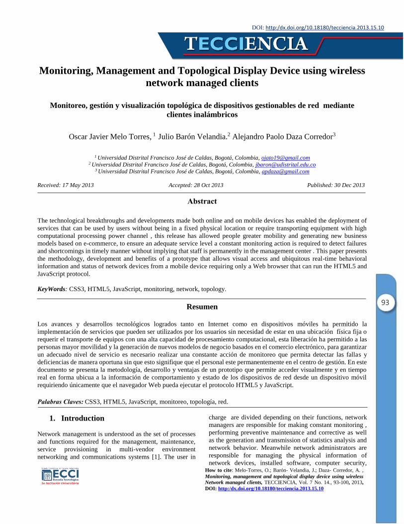
Table 1 shows the main features of the most important tools
for monitoring network, as selection criteria were taking,
Free Software, licensed software and businesses worldwide
focus in the issue of network. As seen in table 1, the tools
meet the requirements that are required for network
management; however none of them present’s visualization
capabilities on mobile devices, only NAGIOS facilitates
monitoring functions via text messages on mobile devices,
being the most important asset of the prototype described
here in.
Table 1. Management tools, network monitoring and
services for mobile devices.
TOOLS FEATURE
MOBILE
DEVICE
DISPLAY
NAGIOS3
Monitoring of network services NO
User notification of events and groups
NO
Notification to phones by SMS
(Short Message Service) SI
Autentification Scheme NO
NETWORK
NODE
MANAGER4
WAN Monitoring NO
Hardware resources Monitoring NO
Alerts NO
Reports and Graphics NO
CISCO
WORKS5
Monitoring LAN y WAN NO
Solutions NO
Monitoring Traffic Management NO
Based on these characteristics, they are summarized as
functional requirements for the development of a mobile
solution topology display network devices, services
monitoring, visualization through mobile devices and
storage network traffic for the generation of alarms and
awareness for registered customers.
3. Prototype development
3.1. Structural Model
3.1.1. Database Design
For the management of persistence the relational database
model was used due to its extensive documentation,
3NAGIOS. http://www.nagios.org/ 4Manage Engine. http://manageengine.adventnet.com/products/opmanager/index.html
5 Cisco. http://www.cisco.com/en/US/support/index.html
95
simplicity and efficiency [4]. Specifically the design of the
prototype Database provides several solutions for the correct
functionality and coherence.
The Entity Relationship design of databases solves several
important features required by the prototype, these features
are described below:
Users: All users in the system are recorded in the
USER table to store basic information for
identification and access to the prototype.
2. Profiles: As described before the prototype
contains of three types of user profiles; Super
Administrator, Administrator and Network
Manager. As these types of user actors were
considered for the development of functional
requirements, the table that stores these profiles is
called ACTOR.
Permissions. Profiles also have a set of
permissions that are reflected in the database as the
relationship between actors and prototype services
to which they have access. Since these services are
available in the Web pages, such relationship
between actors and the services are rendered as the
link JSP resource [5] that encode or generate such
Web pages. This relationship is available in the
MODULE table, and direction of resources is
recorded as relative addresses to the place where
the prototype is installed.
Device synchronization. This service carry out
constant updating of information manageable
assets devices, this information is stored and
updated in the DEVICE table to differentiate the
devices that are in transmission and the ones that
not.
Network Topology. The network topology is
reflected in the database through the relation of 3
tables; LOCATION – DEVICE –CONNECTION,
such relationship is summarized in the following
semantic rule: each device is connected to another
from different Locations.
3.1.2. Structural Design
In the structure of the prototype were used four different
design patterns for the implementation; [6] for the
construction of prototype model types [7]. The main concern
was the simplicity of implementation with the speed to put
into operation. Part of the functionality is based on other
existing developments, Open Source, is the case of the
GraphViz tool used as interface to represent the model of
network nodes to monitor.
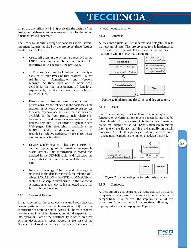
3.1.3. Command
Allows encapsulate all user requests and delegate them to
the relevant objects. This prototype pattern is implemented
to execute the ping and Telnet function in the case of
interaction with the network, see Figure 1.
Figure 1. Implementing the Command design pattern.
3.1.4. Facade
Sometimes a library or set of libraries containing a set of
functions to perform various actions repeatedly invoked by
other libraries. In these cases, it is desirable to create an
object that simplifies the API (Application Programming
Interface) of the library, unifying and simplifying certain
processes API. In this prototype pattern for centralized
management restrictions are implemented, see figure 2.
Figure 2. Implementing the Facade design pattern
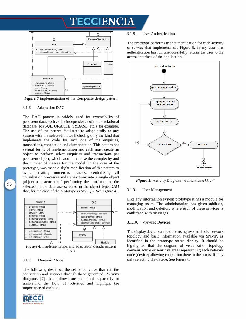
3.1.5. Composite
Allows building a structure of elements that can be treated
independent regardless of the state of these in terms of
composition. It is essential the implementation of this
pattern to form the network at runtime, allowing the
topological states and display, see Figure 3.
96
Figure 3 implementation of the Composite design pattern
3.1.6. Adaptation DAO
The DAO pattern is widely used for extensibility of
persistent data, such as the independence of motor relational
database (MySQL, ORACLE, SYBASE, etc.), for example.
The use of the pattern facilitates to adapt easily to any
system with the selected motor including only the kind that
implements the code for each one of the enquiries,
transactions, connection and disconnection. This pattern has
several forms of implementation and each must create an
object to perform select enquiries and transactions per
persistent object, which would increase the complexity and
the number of classes for the model. In the case of the
prototype, was made a slight modification of this pattern to
avoid creating numerous classes, centralizing all
consultation processes and transactions into a single object
(object persistence) and performing the translation to the
selected motor database selected in the object type DAO
that, for the case of the prototype is MySQL. See Figure 4.
Figure 4. Implementation and adaptation design pattern
DAO
3.1.7. Dynamic Model
The following describes the set of activities thar run the
application and services through these generated. Activity
diagrams [7] that follows are explained separately to
understand the flow of activities and highlight the
importance of each one.
3.1.8. User Authentication
The prototype performs user authentication for each activity
or service that implements see Figure 5, in any case that
authentication has run unsuccessfully returns the user to the
access interface of the application.
Figure 5. Activity Diagram “Authenticate User”
3.1.9. User Management
Like any information system prototype it has a module for
managing users. The administration has given addition,
modification and deletion, where each of these services is
confirmed with messages.
3.1.10. Viewing Devices
The display device can be done using two methods: network
topology and basic information available via SNMP, as
identified in the prototype status display. It should be
highlighted that the diagram of visualization topology
contains active or sensitive areas representing each network
node (device) allowing entry from there to the status display
only selecting the device. See Figure 6.
97
Figure 6. Activity Diagram “Display Devices”
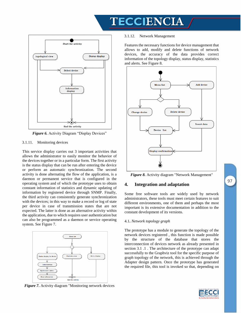
3.1.11. Monitoring devices
This service display carries out 3 important activities that
allows the administrator to easily monitor the behavior of
the devices together or in a particular form. The first activity
is the status display that can be run after entering the device
or perform an automatic synchronization. The second
activity is done alternating the flow of the application, is a
daemon or permanent service that is configured in the
operating system and of which the prototype uses to obtain
constant information of statistics and dynamic updating of
information by registered device through SNMP. Finally,
the third activity can consistently generate synchronization
with the devices; in this way to make a record or log of state
per device in case of transmission states that are not
expected. The latter is done as an alternative activity within
the application, due to which requires user authentication but
can also be programmed as a daemon or service operating
system. See Figure 7.
Figure 7. Activity diagram "Monitoring network devices
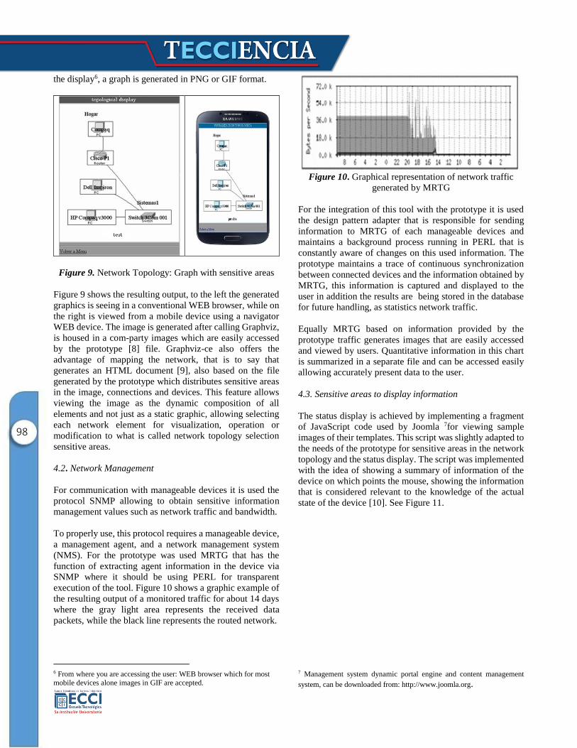
3.1.12. Network Management
Features the necessary functions for device management that
allows to add, modify and delete functions of network
devices, the accuracy of the data provides correct
information of the topology display, status display, statistics
and alerts. See Figure 8.
Figure 8. Activity diagram "Network Management"
4. Integration and adaptation
Some free software tools are widely used by network
administrators, these tools must meet certain features to suit
different environments, one of them and perhaps the most
important is its extensive documentation in addition to the
constant development of its versions.
4.1. Network topology graph
The prototype has a module to generate the topology of the
network devices registered , this function is made possible
by the structure of the database that stores the
interconnection of devices network as already presented in
section 3.1 .1 . The architecture of the prototype can adapt
successfully to the Graphviz tool for the specific purpose of
graph topology of the network, this is achieved through the
Adapter design pattern. Once the prototype has generated
the required file, this tool is invoked so that, depending on
98
the display6, a graph is generated in PNG or GIF format.
Figure 9. Network Topology: Graph with sensitive areas
Figure 9 shows the resulting output, to the left the generated
graphics is seeing in a conventional WEB browser, while on
the right is viewed from a mobile device using a navigator
WEB device. The image is generated after calling Graphviz,
is housed in a com-party images which are easily accessed
by the prototype [8] file. Graphviz-ce also offers the
advantage of mapping the network, that is to say that
generates an HTML document [9], also based on the file
generated by the prototype which distributes sensitive areas
in the image, connections and devices. This feature allows
viewing the image as the dynamic composition of all
elements and not just as a static graphic, allowing selecting
each network element for visualization, operation or
modification to what is called network topology selection
sensitive areas.
4.2. Network Management
For communication with manageable devices it is used the
protocol SNMP allowing to obtain sensitive information
management values such as network traffic and bandwidth.
To properly use, this protocol requires a manageable device,
a management agent, and a network management system
(NMS). For the prototype was used MRTG that has the
function of extracting agent information in the device via
SNMP where it should be using PERL for transparent
execution of the tool. Figure 10 shows a graphic example of
the resulting output of a monitored traffic for about 14 days
where the gray light area represents the received data
packets, while the black line represents the routed network.
6 From where you are accessing the user: WEB browser which for most
mobile devices alone images in GIF are accepted.
Figure 10. Graphical representation of network traffic
generated by MRTG
For the integration of this tool with the prototype it is used
the design pattern adapter that is responsible for sending
information to MRTG of each manageable devices and
maintains a background process running in PERL that is
constantly aware of changes on this used information. The
prototype maintains a trace of continuous synchronization
between connected devices and the information obtained by
MRTG, this information is captured and displayed to the
user in addition the results are being stored in the database
for future handling, as statistics network traffic.
Equally MRTG based on information provided by the
prototype traffic generates images that are easily accessed
and viewed by users. Quantitative information in this chart
is summarized in a separate file and can be accessed easily
allowing accurately present data to the user.
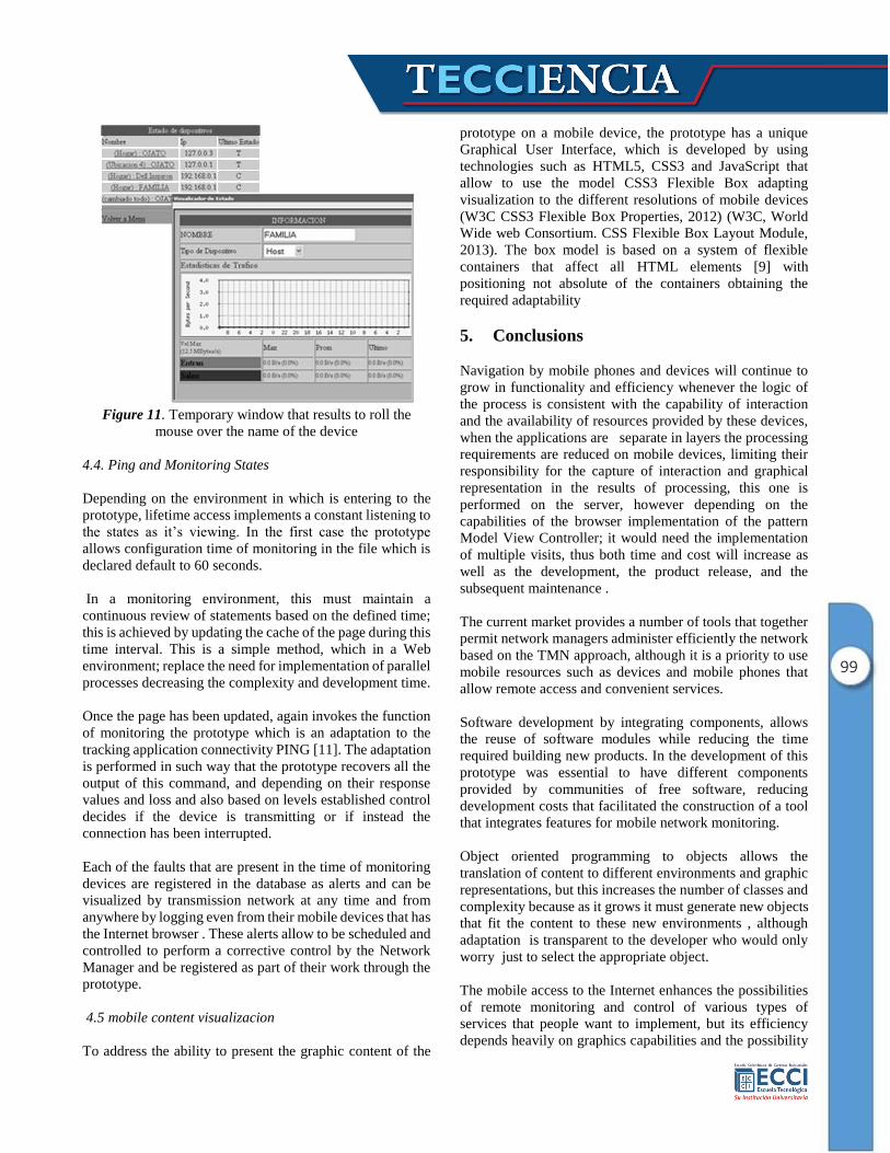
4.3. Sensitive areas to display information
The status display is achieved by implementing a fragment
of JavaScript code used by Joomla 7for viewing sample
images of their templates. This script was slightly adapted to
the needs of the prototype for sensitive areas in the network
topology and the status display. The script was implemented
with the idea of showing a summary of information of the
device on which points the mouse, showing the information
that is considered relevant to the knowledge of the actual
state of the device [10]. See Figure 11.
7 Management system dynamic portal engine and content management
system, can be downloaded from: http://www.joomla.org.
99
Figure 11. Temporary window that results to roll the
mouse over the name of the device
4.4. Ping and Monitoring States
Depending on the environment in which is entering to the
prototype, lifetime access implements a constant listening to
the states as it’s viewing. In the first case the prototype
allows configuration time of monitoring in the file which is
declared default to 60 seconds.
In a monitoring environment, this must maintain a
continuous review of statements based on the defined time;
this is achieved by updating the cache of the page during this
time interval. This is a simple method, which in a Web
environment; replace the need for implementation of parallel
processes decreasing the complexity and development time.
Once the page has been updated, again invokes the function
of monitoring the prototype which is an adaptation to the
tracking application connectivity PING [11]. The adaptation
is performed in such way that the prototype recovers all the
output of this command, and depending on their response
values and loss and also based on levels established control
decides if the device is transmitting or if instead the
connection has been interrupted.
Each of the faults that are present in the time of monitoring
devices are registered in the database as alerts and can be
visualized by transmission network at any time and from
anywhere by logging even from their mobile devices that has
the Internet browser . These alerts allow to be scheduled and
controlled to perform a corrective control by the Network
Manager and be registered as part of their work through the
prototype.
4.5 mobile content visualizacion
To address the ability to present the graphic content of the
prototype on a mobile device, the prototype has a unique
Graphical User Interface, which is developed by using
technologies such as HTML5, CSS3 and JavaScript that
allow to use the model CSS3 Flexible Box adapting
visualization to the different resolutions of mobile devices
(W3C CSS3 Flexible Box Properties, 2012) (W3C, World
Wide web Consortium. CSS Flexible Box Layout Module,
2013). The box model is based on a system of flexible
containers that affect all HTML elements [9] with
positioning not absolute of the containers obtaining the
required adaptability
5. Conclusions
Navigation by mobile phones and devices will continue to
grow in functionality and efficiency whenever the logic of
the process is consistent with the capability of interaction
and the availability of resources provided by these devices,
when the applications are separate in layers the processing
requirements are reduced on mobile devices, limiting their
responsibility for the capture of interaction and graphical
representation in the results of processing, this one is
performed on the server, however depending on the
capabilities of the browser implementation of the pattern
Model View Controller; it would need the implementation
of multiple visits, thus both time and cost will increase as
well as the development, the product release, and the
subsequent maintenance .
The current market provides a number of tools that together
permit network managers administer efficiently the network
based on the TMN approach, although it is a priority to use
mobile resources such as devices and mobile phones that
allow remote access and convenient services.
Software development by integrating components, allows
the reuse of software modules while reducing the time
required building new products. In the development of this
prototype was essential to have different components
provided by communities of free software, reducing
development costs that facilitated the construction of a tool
that integrates features for mobile network monitoring.
Object oriented programming to objects allows the
translation of content to different environments and graphic
representations, but this increases the number of classes and
complexity because as it grows it must generate new objects
that fit the content to these new environments , although
adaptation is transparent to the developer who would only
worry just to select the appropriate object.
The mobile access to the Internet enhances the possibilities
of remote monitoring and control of various types of
services that people want to implement, but its efficiency
depends heavily on graphics capabilities and the possibility
100
of adequate translation of content, therefore it is important
to consider the advantages provided by the flexible box
model by integrating of CSS3 through the integration with
HTML5 and JavaScript .
References [1] A. Barba Marti, Gestión de red., Catalunya: Ediciones Universitat
Politecnica de catalunya., 1999.
[2] A. Leinwand y K. Fang, Network Management: A practical
perspective., Addison Wesley, 1993.
[3] S. J. Harnedy, Total SNMP: Exploring the Simple Network
Management Protocol, Prentice Hall., 1998.
[4] J. Burch y G. Grudnitski, Diseño de sistemas de información:Teoría y Práctica, Mexico: Limusa, 1992.
[5] A. F. Quintas, Java server Pages: Manual De Usuario Y Tutoria,
Madrid: Ra-Ma, 2001.
[6] E. Gamma, R. Helm, R. Johnson y J. Vlissides, Design Patterns:
Elements of Reusable Object-Oriented Software, Sydney: Pearson Education, 1994.
[7] C. Larman, UML y patrones: introducción al análisis y diseño
orientado a objetos, Prentice Hall, 1999.
[8] A. Weitzenfeld, Ingeniería de Software orientada a objetos con
UML, Java e Internet., Mexico: Thomson, 2005.
[9] T. A. Powell, HTML & XHTML: The Complete Reference, Mc Graw-Hill., 2003.
[10] V. B, «MailXMail Técnicas para el desarrollo de computación
móvil,» 10 12 2012. [En línea].
[11] D. Comer, Interconectividad de redes con TCP/IP. Volumen II,
Diseño e Implementación., Pearson, 2002.