Embed Size (px)
Citation preview
Monitoring and Verification Issues for Carbon Storage
GCCC Digital Publication Series #06-01
Susan D. Hovorka
Cited as: Hovorka, S.D., Monitoring and verification issues for carbon storage: presented as online lecture to Regional Sequestration Partnerships Outreach and Geologic Working Groups, Austin, Texas, 2006. GCCC Digital Publication Series #06-01.
Keywords: Measurement Monitoring and Verification (MMV), Injection Zone- Risks, MMV Technologies, Monitoring Zone Options, Surface Geophysics

Monitoring and Verification Issues for Carbon Storage
Pilot ExperimentsSusan D. Hovorka
Bureau of Economic GeologyJackson School of GeosciencesThe University of Texas at Austin

Measurement, Monitoring and Verification
MM&V is defined as the capability to:Measure the amount of CO2 stored at a specific
sequestration site, Monitor the site for leaks or other deterioration
of storage integrity over time,Verify that the CO2 is stored and unharmful to
the host ecosystem(some add Model and Mitigate)
www.netl.doe.gov

Ask: Why is MMV Needed at This Project?
• Health, Safety, and Environmental concerns• Reservoir economics (ECBM, EOR, EGR)• Required by regulators• Credits/emissions trading/liability reduction• Research objectives• Public Acceptance
– How does the public know that a project is safe?– How do investors know that a project is effective?

Unexpected Results of Injection
Water tableUnderground source of drinking water
Earthquake
Escape to groundwater,surface water, or air via long flowpath
Substitute undergroundinjection for airrelease
Escape of CO2or brine togroundwater,surface wateror air throughflaws in the seal
Failure of well cement orcasing resulting in leakage

Major Impacts of Unexpected Result of Injection
Risk Short term (during injection process)
Long term (after closure)
Seismisity
Failure of well engineering
Leakage over a short path
Leakage over a long path
Impact on atmosphereHealth and safety Environment

MMV for CO2 Already Exists: Use it
• Health and safety procedures for CO2 pipelines, shipping, handling, and storing
• Pre-injection characterization and modeling• Isolation of injectate from Underground Sources of Drinking Water
(USDW)• Maximum allowable surface injection pressure (MASIP)• Mechanical integrity testing (MIT) of engineered system• Standards for well completion and plug and abandonment in cone
of influence and area of review around injection wells.• Reservoir management; extensive experience in modeling and
measuring location of fluids

Keys to Development of Successful Monitoring Program at an
Experimental Injection• Rigorous definition of objectives of monitoring • Adequate pre-injection characterization and
modeling of evolution of conditions post injection
• Sensitivity analysis to match tools to expected or possible signal at the right time
Flow SimulationTOUGH2, Doughty, LBNLSample analysis
(Core Lab)Reservoir model
Knox/Yeh, BEG

Example of Goals: Frio Experiment: Monitoring CO2 Storage in Brine-
Bearing FormationsProject Goal: Early success in a high-permeability, high-volume sandstone representative of a broad area that is an ultimate target for large-volume sequestration.
•Demonstrate that CO2 can be injected into a brine formation without adverse health, safety, or environmental effects
•Determine the subsurface distribution of injected CO2 using diverse monitoring technologies
•Demonstrate validity of conceptual and numerical models
•Develop experience necessary for success of large-scale CO2injection experiments
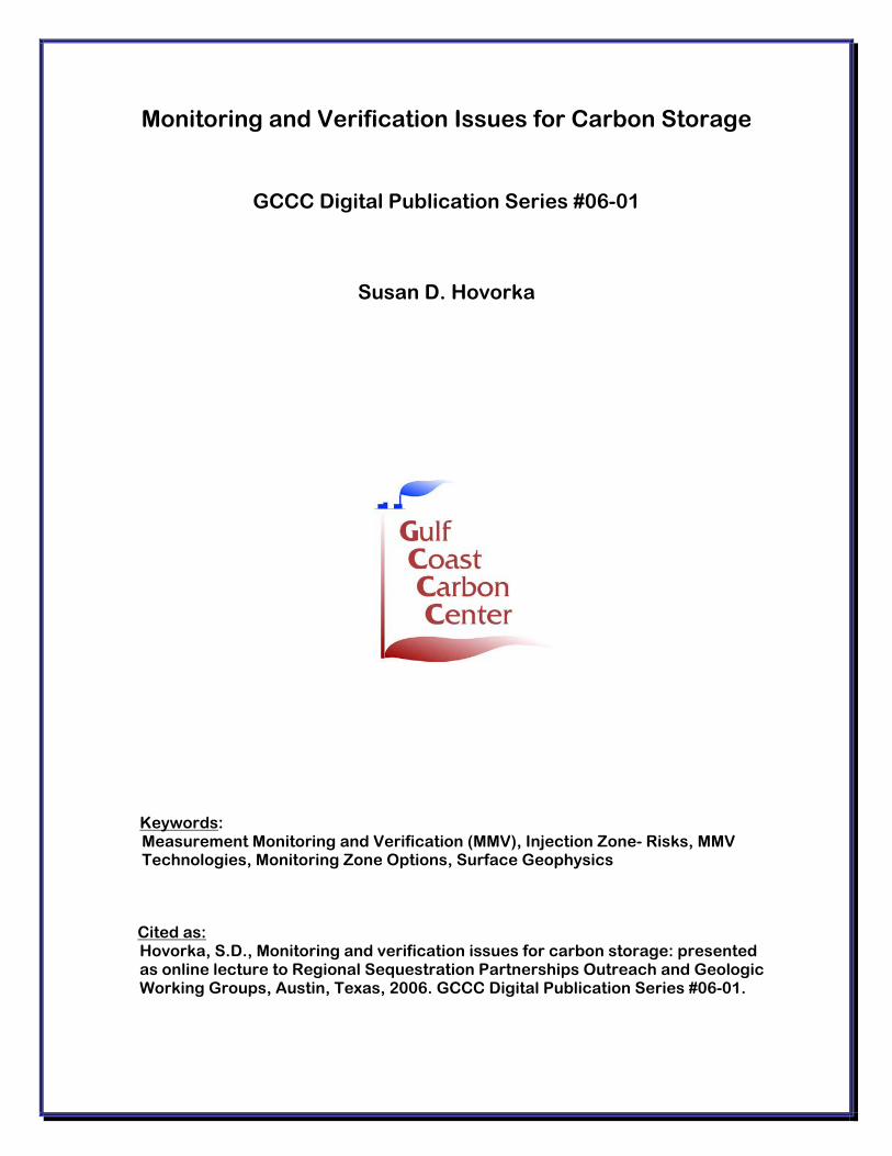
Monitoring at Frio Pilot
DownholeP&T
Radial VSPCross well Seismic, EM
Downhole samplingU-tubeGas lift
Wirelinelogging
Aquifer wells (4)Gas wells Access tubes, gas sampling
Tracers
Determine the subsurface distribution of injected CO2 using diverse monitoring technologies
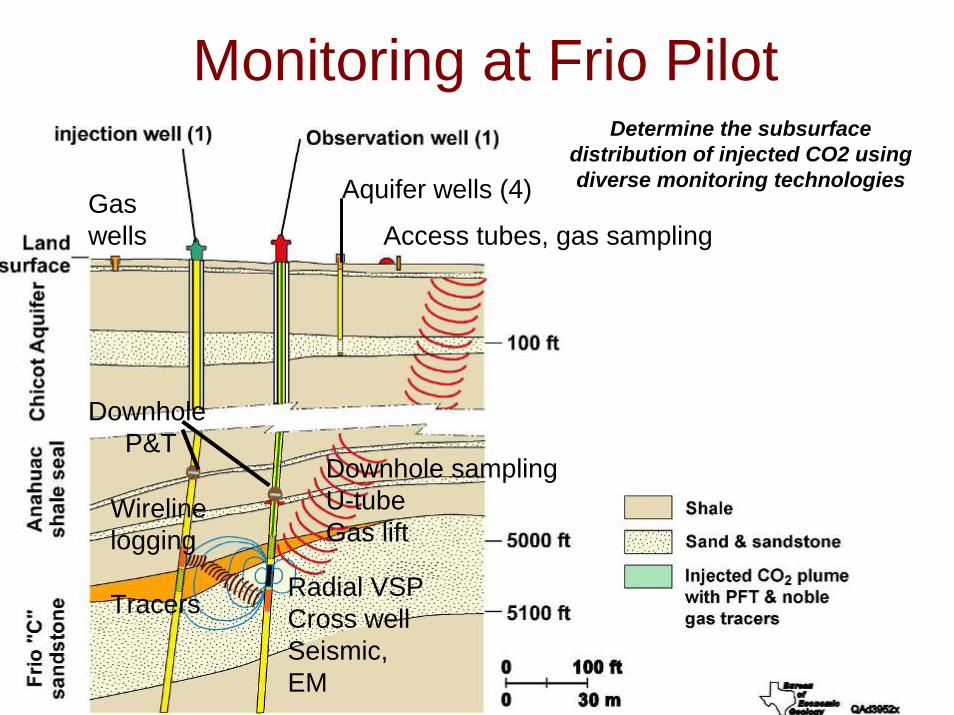
My Recommendations for Designing a MMV Program
• Characterization, modeling, sensitivity, and signal-to-noise analyses are essential
• Rank questions: no one tool is ideal for all questions; Impossible to optimize for all tools
What is the best way to monitor for unexpected events?
Nessie? belcold.com

MMV Technologies
• Intensive monitoring in pilot phases• Effective monitoring during
implementation• The problem of monitoring slow leakage
and long time frames is not yet solved• See study by Benson on costs

Monitoring Zone Options
Aquifer and USDW
AtmosphereBiosphere
Vadose zone & soil
Seal
Seal
• Atmosphere– Ultimate integrator, dynamic
• Biosphere– Requires assurance of no
damage, dynamic• Soil and Vadose Zone
– Integrator but dynamic• Aquifer and USDW
– Integrator, slightly isolated from ecological effects
• Above injection monitoring zone– First indicator, monitor small
signals, more stable. May not integrate
• In-injection zone - plume– Oil-field type technologies. Will not
find small leaks
Monitoring Zone
CO2 plumeConsider also lateral complexities, transport,focused flow paths

Atmospheric Monitoring• Direct detection• Many tools, from
standard monitors to new tools in development
• Applied at many scales• Detection is complicated because of high
ambient CO2 from atmosphere, soil, and vegetation – difficult to isolate small fluxes from subsurface
Real-time CO2 atmospheric monitoring near Naples, Italy

Soil Gas Monitoring• Done at numerous sites volcanic
sites, CO2-EOR• Relatively low cost, integrates
seepage over a time period • Escaped CO2 is likely to be
concentrated in vadose zone• Like air, detection in soil is
complicated because of high ambient CO2
• Flux, composition, isotopes• Coordinate with ecosystem
monitoringhttp://volcanoes.usgs.gov/About/What/Monitor/Gas/soil.html

Groundwater Monitoring
• Standard technique in contaminated sites
• Good regional integrator• Signal of leakage may be
complex• Might be used in
combination with natural or introduced tracers Injector
Aquifer Gradient
Upgradient aquifer Monitoring wells
Down gradient aquifer monitoring wells
30 m

Wireline Well Logging• Well-known oilfield activity• Match tools to rock/fluid
characteristics• Typically good vertical resolution,
quantitative, interpretable• Well bore effects and damage
may lead to errors• Interpolate the interwell areas
Frio post injection cased hole sonic log, Sakurai BEG/Mueller Schlumberger
CO2

Tracers and Geologic Inferences
• Introduced materials that travel with CO2 can uniquely fingerprint migration – Nobel gasses– PFT’s and other chemically unique materials– Detection at very low concentrations
• CO2 can be geochemically unique –– C isotopes– Impurities
• Hydrologic analysis to determinefractional saturation – Capacityassessment
Tracer Breakthrough Curves
-0.2
0
0.2
0.4
0.6
0.8
1
10/10/2004 10/11/2004 10/12/2004 10/13/2004
C/C
max
SF6 C/CmaxKrypton C/CmaxPFT C/Cmax
2nd Tracer Breakthrough
3rd Tracer Breakthrough
Frio noble gas and PFT analysis, Barry Freifeld (LBNL) and Timmy Phelps (ORNL)

Reservoir Pressure and Temperature Responses –Powerful and Inexpensive Tools
Day 1-10
Day 1-10
Sally Benson, LBNL

Surface Geophysics
• Surface seismic imaging – 2D, 3D, 4D
• Alternative methods– Electrical contrasts– Gravity– Passive Seismic
• Interferometry/tilt
Successful time lapse 3- at Sliepner (from Chadwick, 2004)

Time-laps Crosswell Seismic and Vertical Seismic Profiling
• Image host setting and CO2
• Sensitivity to concentration is model dependent
• Resolution limits detection of small volumes
• May not detect slow leakage
Frio X-well Tom Daley, Mike Hoversten, L. Myer, LBNL
Inje
ctor

Non-Seismic Geophysical Tools
• Electromagnetic: LBNL work• Spontaneous Potential • Gravity• Tilt, Interferometry

Conclusions
• Monitoring and verification advances at pilots will benefit the future application of geologic storage of carbon
• Good design to select the right tool to meet the right need at the the right phase of the implementation is important

Information on MMV applied to geologic storage is available from
many sources:A few starters:IPPC Special Report on Carbon Dioxide Capture and Storage, Sept 2005, esp. chapter 5 geologic storage.http://www.ipcc.ch/activity/srccs/index.htmCSLF discussion paper from task force for identifying gaps in CO2 monitoring and verification of storage.http://www.cslforum.org/documents/TaskForce_CO2_Monitoring_Verification.pdfFrio Brine Pilot: www.beg.utexas.edu/co2GEOSEQ: http://www-esd.lbl.gov/GEOSEQ/index.htmlGHGT6, Gale and Kaya, 2003, Pergamon PressGHGT 7, Rubin, Keith, Gilboy/Wilson, Morris, Gale, Thambimathu, 2005, ElsevierPrinceton Carbon Mitigation Initiative http://www.princeton.edu/~cmi/MIT Carbon Sequestration Initiative http://sequestration.mit.eduCarbon Capture Project JIP http://www.co2captureproject.org/index.htmIEA Greenhouse Gas R&D http://www.ieagreen.org.ukDOE NETL: http://www.fe.doe.gov/programs/sequestration/