Embed Size (px)
Citation preview
A
iCufefp©
K
1
ppatupavqfdpvm
f
0d
Available online at www.sciencedirect.com
Journal of Power Sources 173 (2007) 925–934
Molten carbonate fuel cell operation with dual fuel flexibility
Joseph Daly a, George Steinfeld a, David K. Moyer b, Franklin H. Holcomb c,∗a FuelCell Energy Inc., 3 Great Pasture Road, Danbury, CT 06813-1305, United States
b Concurrent Technologies Corporation, 100 CTC Drive, Johnstown, PA 15904-1935, United Statesc U.S. Army Engineer Research and Development Center, Construction Engineering Research Laboratory,
2902 Newmark Drive, Champaign, IL 61822-1076, United States
Received 2 July 2007; accepted 3 August 2007Available online 19 August 2007
bstract
The ability to operate highly efficient, pollution-free, distributed-generation power plants on either natural gas or HD-5 grade propane is ofnterest to the U.S. Army and the U.S. Department of Homeland Security as secure power for critical power operations. To address this interest,oncurrent Technologies Corporation (CTC) teamed with FuelCell Energy (FCE) to test an internally reforming 250 kW carbonate fuel cellsing HD-5 propane. This fuel cell power plant, originally designed to operate on pipeline natural gas or digester gas, was modified for dualuel operation (natural gas and propane). Fuel cell operation using HD-5 propane was demonstrated for over 3900 h and achieved high-electrical
fficiency (45.7–47.1% lower heating value (LHV)) over a broad range of power outputs. In addition, instantaneous and on-load fuel switchingrom natural gas to propane and back was demonstrated without loss of power. This dual fuel power plant operates efficiently on either fuel androvides the U.S. Army and other power users with a viable technology solution for critical power operations.2007 Elsevier B.V. All rights reserved.
cUswfaomiopw
eywords: Fuel cell; Dual fuel; Fuel swap; Propane; Critical power
. Introduction
Continuous, long-term operation of a fuel cell on HD-5ropane provides a viable option to islands, remote sites, nationalarks, data centers, military bases, hotels, and hospitals withoutnatural gas infrastructure. Although natural gas distribution
hrough utility pipelines is convenient, it is vulnerable to nat-ral disaster, threats of terrorism, and repair outages. Propanerovides an alternative local fuel supply routinely transportednd stored as a liquid at ambient temperatures and offers a con-enient and secure option for fuel cell operations. An adequateuantity of propane can be stored on-site to sustain operationsor several days pending a fuel delivery or until any natural gasisturbance is restored. The possibility of operating a fuel cell
ower plant on HD-5 propane, as a back-up to natural gas, pro-ides a valuable proposition for the U.S. Army’s initiative toinimize the impact of fuel availability [1–3].∗ Corresponding author. Tel.: +1 217 373 5864.E-mail addresses: [email protected],
[email protected] (F.H. Holcomb).
ufpdofpD
378-7753/$ – see front matter © 2007 Elsevier B.V. All rights reserved.oi:10.1016/j.jpowsour.2007.08.035
In response to the interest for a fuel flexible power plant, Con-urrent Technologies Corporation (CTC), under contract to the.S. Army Engineer Research and Development Center, Con-
truction Engineering Research Laboratory (ERDC–CERL),orked with FuelCell Energy (FCE) to test a 250 kW carbonate
uel cell power plant operating on propane at the Fuel Cell Testnd Evaluation Center (FCTec). Prior experience established theperation of a fuel cell power plant on natural gas [4], so the pri-ary objective of this project was to demonstrate HD-5 propane
s also a viable fuel for continuous, high power, high efficiencyperation of FCE’s Direct Fuel Cell® (DFC®) power plants. Thisroject employed a DFC300A, a 300 kW fuel cell power plantith a nominal output of 250 kW.A secondary goal was to demonstrate propane as a back-
p fuel to natural gas, with the added benefit of instantaneousuel swapping from natural gas to propane. This fuel flexibilityrovides secure power in the event of sudden and unexpectedisruption to the natural gas pipeline supply. HD-5 propane, as
pposed to other grades of propane, was selected as the back-upuel of choice based on availability, even in remote areas, andreliminary success processing the HD-5 propane in a full-scaleFC demonstration facility [5].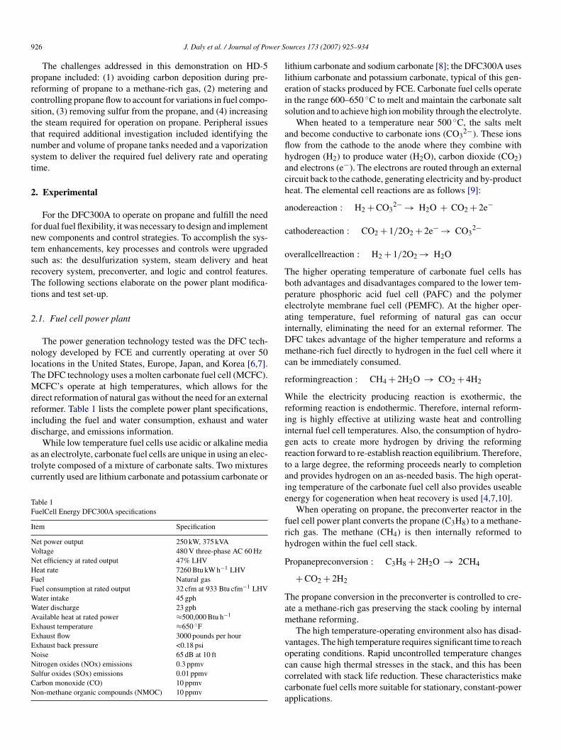
9 wer S
prcsttnst
2
fntsrTt
2
nlTMdrid
atc
TF
I
NVNHFFWWAEEENNSCN
lleis
aflhach
a
c
o
TbpeaiDmc
r
Wrii
26 J. Daly et al. / Journal of Po
The challenges addressed in this demonstration on HD-5ropane included: (1) avoiding carbon deposition during pre-eforming of propane to a methane-rich gas, (2) metering andontrolling propane flow to account for variations in fuel compo-ition, (3) removing sulfur from the propane, and (4) increasinghe steam required for operation on propane. Peripheral issueshat required additional investigation included identifying theumber and volume of propane tanks needed and a vaporizationystem to deliver the required fuel delivery rate and operatingime.
. Experimental
For the DFC300A to operate on propane and fulfill the needor dual fuel flexibility, it was necessary to design and implementew components and control strategies. To accomplish the sys-em enhancements, key processes and controls were upgradeduch as: the desulfurization system, steam delivery and heatecovery system, preconverter, and logic and control features.he following sections elaborate on the power plant modifica-
ions and test set-up.
.1. Fuel cell power plant
The power generation technology tested was the DFC tech-ology developed by FCE and currently operating at over 50ocations in the United States, Europe, Japan, and Korea [6,7].he DFC technology uses a molten carbonate fuel cell (MCFC).CFC’s operate at high temperatures, which allows for the
irect reformation of natural gas without the need for an externaleformer. Table 1 lists the complete power plant specifications,ncluding the fuel and water consumption, exhaust and waterischarge, and emissions information.
While low temperature fuel cells use acidic or alkaline medias an electrolyte, carbonate fuel cells are unique in using an elec-rolyte composed of a mixture of carbonate salts. Two mixturesurrently used are lithium carbonate and potassium carbonate or
able 1uelCell Energy DFC300A specifications
tem Specification
et power output 250 kW, 375 kVAoltage 480 V three-phase AC 60 Hzet efficiency at rated output 47% LHVeat rate 7260 Btu kW h−1 LHVuel Natural gasuel consumption at rated output 32 cfm at 933 Btu cfm−1 LHVater intake 45 gphater discharge 23 gphvailable heat at rated power ≈500,000 Btu h−1
xhaust temperature ≈650 ◦Fxhaust flow 3000 pounds per hourxhaust back pressure <0.18 psioise 65 dB at 10 ftitrogen oxides (NOx) emissions 0.3 ppmvulfur oxides (SOx) emissions 0.01 ppmvarbon monoxide (CO) 10 ppmvon-methane organic compounds (NMOC) 10 ppmv
grtaie
frh
P
Tam
voccca
ources 173 (2007) 925–934
ithium carbonate and sodium carbonate [8]; the DFC300A usesithium carbonate and potassium carbonate, typical of this gen-ration of stacks produced by FCE. Carbonate fuel cells operaten the range 600–650 ◦C to melt and maintain the carbonate saltolution and to achieve high ion mobility through the electrolyte.
When heated to a temperature near 500 ◦C, the salts meltnd become conductive to carbonate ions (CO3
2−). These ionsow from the cathode to the anode where they combine withydrogen (H2) to produce water (H2O), carbon dioxide (CO2)nd electrons (e−). The electrons are routed through an externalircuit back to the cathode, generating electricity and by-producteat. The elemental cell reactions are as follows [9]:
nodereaction : H2 + CO32− → H2O + CO2 + 2e−
athodereaction : CO2 + 1/2O2 + 2e− → CO32−
verallcellreaction : H2 + 1/2O2 → H2O
he higher operating temperature of carbonate fuel cells hasoth advantages and disadvantages compared to the lower tem-erature phosphoric acid fuel cell (PAFC) and the polymerlectrolyte membrane fuel cell (PEMFC). At the higher oper-ting temperature, fuel reforming of natural gas can occurnternally, eliminating the need for an external reformer. TheFC takes advantage of the higher temperature and reforms aethane-rich fuel directly to hydrogen in the fuel cell where it
an be immediately consumed.
eformingreaction : CH4 + 2H2O → CO2 + 4H2
hile the electricity producing reaction is exothermic, theeforming reaction is endothermic. Therefore, internal reform-ng is highly effective at utilizing waste heat and controllingnternal fuel cell temperatures. Also, the consumption of hydro-en acts to create more hydrogen by driving the reformingeaction forward to re-establish reaction equilibrium. Therefore,o a large degree, the reforming proceeds nearly to completionnd provides hydrogen on an as-needed basis. The high operat-ng temperature of the carbonate fuel cell also provides useablenergy for cogeneration when heat recovery is used [4,7,10].
When operating on propane, the preconverter reactor in theuel cell power plant converts the propane (C3H8) to a methane-ich gas. The methane (CH4) is then internally reformed toydrogen within the fuel cell stack.
ropanepreconversion : C3H8 + 2H2O → 2CH4
+ CO2 + 2H2
he propane conversion in the preconverter is controlled to cre-te a methane-rich gas preserving the stack cooling by internalethane reforming.The high temperature-operating environment also has disad-
antages. The high temperature requires significant time to reach
perating conditions. Rapid uncontrolled temperature changesan cause high thermal stresses in the stack, and this has beenorrelated with stack life reduction. These characteristics makearbonate fuel cells more suitable for stationary, constant-powerpplications.
wer S
2o
ooima
2
tiaastafrbssspfc
tdflwaisfwvla
btlspetwroiwi
stTlw
sitvtoivptehtc
td0pfpwtsvtp
2
fcmtia
2
pDDDe
J. Daly et al. / Journal of Po
.2. Power plant modification for propane and dual fuelperation
The DFC300A power plant was modified to accommodateperation on propane while maintaining the ability to operaten natural gas and to facilitate rapid fuel switching. Changesncluded piping and equipment modifications, additional instru-
entation, and the logic and controls to interpret the new signalsnd drive the new processes.
.3. Propane supply and delivery
The HD-5 propane was stored outdoors in two above groundanks (identified as Tanks A and B) each having a 2000 gal capac-ty. The usable volume of each tank was about 65% of capacity, orpproximately 1300 gal; the top 20% is reserved for expansion,nd the bottom 15% is maintained as a buffer to prevent exces-ive drawdown. When the fuel cell was operating at full load,he usable tank volume lasted approximately 2.5 days beforeutomatically switching to Tank B. The DFC300A approximateuel consumption of 520 gal/day necessitated the tanks to beefilled every 3–5 days. Sample ports were located to facilitateoth vapor and liquid sampling for characterization of the fuelupply. Fig. 1 shows a schematic of the propane storage andupply system. In addition to the propane storage system, thechematic also identifies: a temporary tanker that was used forropane spiked with propylene, the flow stabilizers initially usedor enhanced vaporization, and the interconnecting piping andontrols.
The initial fuel delivery strategy employed flow stabilizerso maintain propane vapor pressure; initially tanks were drawnown sequentially, first Tank A and then Tank B. Sequentialuel consumption was accomplished with an automated iso-ation valve on the Tank A vapor output. This valve closedhen a remote level sensor on Tank A indicated depletion to
pproximately 15% of capacity. Tank A and Tank B each hadndependent regulators, with the regulated pressure of Tank Aet 2 psi higher than Tank B. In this way, vapor was deliveredrom Tank A as long as the isolation valve was open, and Tank Bould passively begin to deliver flow once the Tank A isolationalve was closed. When Tank A was refilled to greater than 15%evel, the isolation valve would open and Tank A would oncegain become the primary fuel source.
The flow stabilizer is activated when the tank pressure fallselow 30 psig; a pressure switch (Fig. 1) is used to monitor theank vapor pressure. Low tank pressure is attained when theiquid propane reaches −12 ◦C by consequence of fuel con-umption rate and ambient temperature. The flow stabilizerrovides heat to the propane by heat exchange with a heatedthylene glycol–water loop in an external heat exchanger. Thus,he propane liquid is pumped out of the tank cold and returnedarm. The flow stabilizers turn off when the tank pressure
eaches 40 psig (i.e., a 10 psi dead band). Although this approach
perated as designed, the sulfur concentration increased dur-ng flow stabilizer operation. This may have resulted from thearmed liquid being introduced back into the vapor area, allow-ng increased vaporization of the heavy hydrocarbons containing
Ctgp
ources 173 (2007) 925–934 927
ulfur. A resolution may be to introduce the warmed liquid intohe bottom of the tank, hence mixing it with the existing liquid.his methodology was not tested within this effort due to the
ogistical limitations of making necessary piping modificationshile fuel occupied the tank.To avoid increased sulfur concentration, the fuel delivery
trategy was modified to eliminate the flow stabilizers; vapor-zation from ambient heat only was pursued. In this case bothanks were used in parallel. Use of a common regulator on theapor output of the two tanks helped assure both tanks main-ain the same liquid level. If one tank volume is higher than thether, the higher volume tank will be able to gain heat more read-ly from the ambient temperature, therefore providing a greaterapor pressure. This will cause the higher volume tank to deliverropane vapor preferentially until its level falls to that of the otherank. This approach proved to be simple and effective. Ambi-nt heat vaporization provided a more consistent fuel supply;owever, a sufficiently sized tank or multiple tanks are neededo maintain the required pressure, especially in seasonally coldlimate regions.
As per the fuel specification [11], HD-5 propane may con-ain up to 5% propylene, but the HD-5 as received during thisemonstration contained very low propylene on the order of.1%. To create a rigorous test of potential commercial fuel com-ositions, propylene was added to the stock HD-5 propane toorce the concentration of propylene to approximately 5%. Thisropylene-spiked HD-5 was stored in a separate tanker trailerith a capacity of 11,200 gal. The tanker was staged adjacent to
he HD-5 storage area and piped into the propane distributionystem (Fig. 1). When propylene-spiked HD-5 was needed, thealves supplying as-delivered HD-5 propane were closed andhe valve to the tanker was opened. The change-over to the 5%ropylene-spiked propane was performed manually.
.4. Natural gas delivery
Natural gas was supplied through the existing natural gasuel train. The in-house 5 psig feed flowed through a natural gasompressor system to increase the line pressure to the 15 psiginimum gas pressure required for full load power plant opera-
ion. Natural gas compression is not necessary for the DFC300Af a continuous natural gas utility pressure of 15 psig is availablet the installation site.
.5. Electrical connections
A 480Y/277 V three-phase electrical distribution feeder sup-lied the necessary DFC300A utility electrical connection.uring start up and while operating in hot stand-by, theFC300A consumed (received) power through this connection.uring normal power generation, power was exported (deliv-
red) to the utility electrical grid through this same connection.The DFC300A also has a customer critical bus (CCB). The
CB remains energized in the event of grid disruption providedhe fuel cell power plant is producing power equivalent to orreater than the CCB load. For this demonstration, the CCBrovided power to an AC load bank and the natural gas com-
928 J. Daly et al. / Journal of Power Sources 173 (2007) 925–934
and d
pcdtpa
eupca
gpepumippppgau
im
2
pgetSosd
osssDti
Fig. 1. Propane storage
ressor. In commercial application scenarios, the CCB would beonnected to critical devices allowing for continued operationsuring an electric utility disturbance. A separate 480Y/277 Vhree-phase electrical distribution panel supplied power to theropane vaporization system, including the two flow stabilizersnd the necessary propane level-sensing equipment.
For this test program’s energy analysis and efficiency review,ach of the four electrical connections presented above (onetility grid connection, two CCB connections, and the propaneower panel) were independently recorded to monitor electri-al parameters allowing accurate and detailed calculations andnalyses.
The DFC300A power plant can operate in grid connect orrid independent modes. During this demonstration, the fuel cellower plant normally was operated in grid connect mode. How-ver, in a simulated grid outage scenario, the DFC300A powerlant seamlessly separated from the electrical grid and contin-ed to operate in grid-independent mode. In grid-independentode, the power plant needs to produce a minimum of approx-
mately 15 kW AC to support the internal fuel cell power plantarasitic loads. Additional loads of up to 225 kW may also beresent on the CCB during a grid outage. Upon grid outage, theower plant load will drop from the grid connect load to the
arasitic load plus CCB loads. If the sum of the CCB loads arereater than the previous grid connect load, potentially causingn unacceptable instantaneous rise in fuel cell power plant outputpon transition to grid-independent mode, or if the fuel supply isbuTt
istribution schematic.
nterrupted, the DFC300A will shut down automatically in a safeanner.
.6. Gas sampling and analysis
Gas analyses were performed on the fuel cell’s inlet fuel com-osition, anode inlet and exit gases, and cathode inlet and exitases. These analyses were used to determine fuel utilization,stablish operating parameters, and investigate any irregulari-ies. The inlet fuel was also analyzed regularly for sulfur content.ulfur analysis provides a means for estimating the useful lifef the desulfurizing adsorbent and indicates the presence ofulfur break-through after the desulfurizer adsorbent becomesepleted.
Most fuel cell reforming processes require water in the formf steam to avoid carbon and produce hydrogen for use in the celltack [12,13]. The DFC power plant is no different; therefore, aignificant amount of water vapor is present in the anode gasesuch as the preconverter, reformer inlet, and reformer outlet.uring sampling and analysis of these gases, special precau-
ions are taken to prevent water from entering the analyticalnstruments such as the gas chromatograph (GC) and sensors.
A sample apparatus consisting of a control valve, desiccant
ed of drierite, a flow control rotameter, and air-powered vac-um was used to draw gases from each port on the fuel cell.he apparatus was connected to the sample port and plumbed tohe GC. Sample gas was first passed through the control valve
wer Sources 173 (2007) 925–934 929
utbdascowwsAwd
3
p2tFkppcaoppo
3
egno
oc
Table 2Electrical efficiency of the DFC300A fuel cell power plant operating on naturalgas and propane
Power level Determined plant efficienciesa (% LHV)
Natural gas Propane
1/2 Load (∼130 kW) 44.5 47.13/4 Load (∼200 kW) 47.0 46.1F
c
baaatosTtii
3
mmtiaercpcadepleted, and Fig. 4 shows the effect on the fuel gas LHV, hydro-
J. Daly et al. / Journal of Po
sed to initially control flow. Next, the gas was passed throughhe desiccant bed to dry the sample. Following the desiccanted, provision was made to insert a stainless steel sample cylin-er to allow for collection of an additional sample for shipmentnd evaluation at another laboratory. From this connection, theample was diverted to the GC sample line. Gas samples wereollected from the T-connection using the internal sample pumpf the GC instrument. The gas next flowed through the rotameter,hich indicated the GC sample rate. A target flow of 1 L min−1
as typically used. The flow was adjusted by varying the pres-ure of the air-powered ejector and by the sample control valve.ll gases, including inlet air to the cathode and incoming fuel,ere sampled through the apparatus to ensure that completelyry samples were analyzed.
. Results and discussion
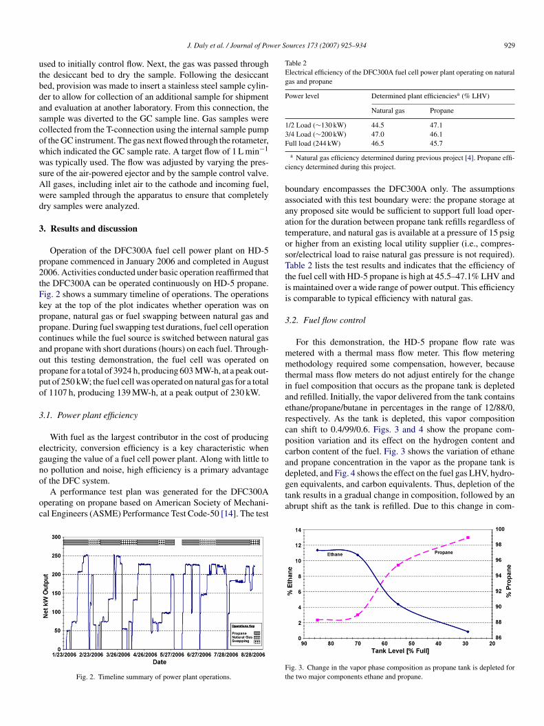
Operation of the DFC300A fuel cell power plant on HD-5ropane commenced in January 2006 and completed in August006. Activities conducted under basic operation reaffirmed thathe DFC300A can be operated continuously on HD-5 propane.ig. 2 shows a summary timeline of operations. The operationsey at the top of the plot indicates whether operation was onropane, natural gas or fuel swapping between natural gas andropane. During fuel swapping test durations, fuel cell operationontinues while the fuel source is switched between natural gasnd propane with short durations (hours) on each fuel. Through-ut this testing demonstration, the fuel cell was operated onropane for a total of 3924 h, producing 603 MW-h, at a peak out-ut of 250 kW; the fuel cell was operated on natural gas for a totalf 1107 h, producing 139 MW-h, at a peak output of 230 kW.
.1. Power plant efficiency
With fuel as the largest contributor in the cost of producinglectricity, conversion efficiency is a key characteristic whenauging the value of a fuel cell power plant. Along with little too pollution and noise, high efficiency is a primary advantage
f the DFC system.A performance test plan was generated for the DFC300Aperating on propane based on American Society of Mechani-al Engineers (ASME) Performance Test Code-50 [14]. The test
Fig. 2. Timeline summary of power plant operations.
gta
Ft
ull load (244 kW) 46.5 45.7
a Natural gas efficiency determined during previous project [4]. Propane effi-iency determined during this project.
oundary encompasses the DFC300A only. The assumptionsssociated with this test boundary were: the propane storage atny proposed site would be sufficient to support full load oper-tion for the duration between propane tank refills regardless ofemperature, and natural gas is available at a pressure of 15 psigr higher from an existing local utility supplier (i.e., compres-or/electrical load to raise natural gas pressure is not required).able 2 lists the test results and indicates that the efficiency of
he fuel cell with HD-5 propane is high at 45.5–47.1% LHV ands maintained over a wide range of power output. This efficiencys comparable to typical efficiency with natural gas.
.2. Fuel flow control
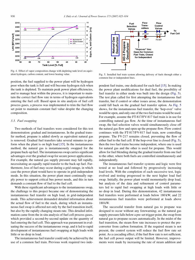
For this demonstration, the HD-5 propane flow rate wasetered with a thermal mass flow meter. This flow meteringethodology required some compensation, however, because
hermal mass flow meters do not adjust entirely for the changen fuel composition that occurs as the propane tank is depletednd refilled. Initially, the vapor delivered from the tank containsthane/propane/butane in percentages in the range of 12/88/0,espectively. As the tank is depleted, this vapor compositionan shift to 0.4/99/0.6. Figs. 3 and 4 show the propane com-osition variation and its effect on the hydrogen content andarbon content of the fuel. Fig. 3 shows the variation of ethanend propane concentration in the vapor as the propane tank is
en equivalents, and carbon equivalents. Thus, depletion of theank results in a gradual change in composition, followed by anbrupt shift as the tank is refilled. Due to this change in com-
ig. 3. Change in the vapor phase composition as propane tank is depleted forhe two major components ethane and propane.
930 J. Daly et al. / Journal of Power Sources 173 (2007) 925–934
Fa
pptatepsc
3
dfifmpaFntcmpd
timtnbmwfudl
u
Fc
ptfTtcswFcstcpetfati
tlesbtnfi1
dsnfc
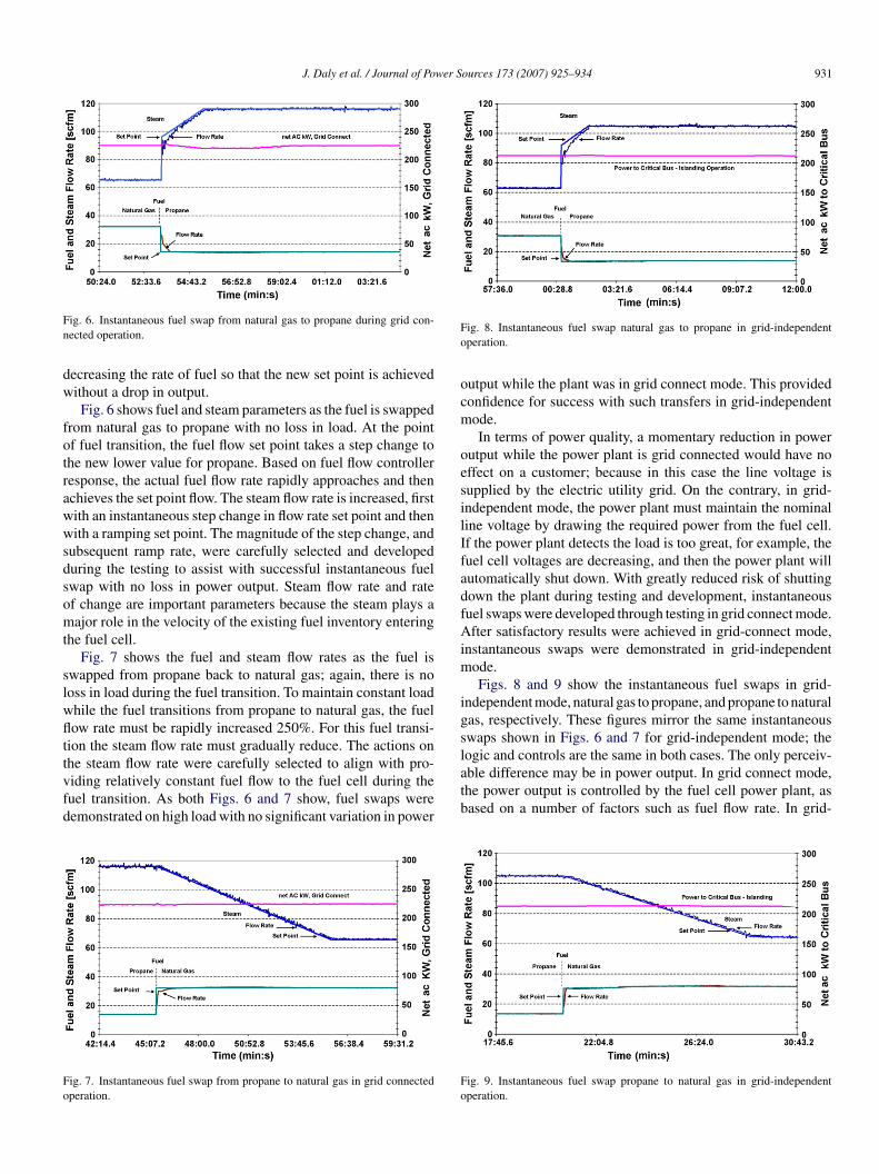
ig. 4. Effect of vapor composition change with depleting tank level on equiv-lent hydrogen, carbon content, and lower heating value.
osition, the fuel supplied to the power plant will be hydrogenoor when the tank is full and will become hydrogen rich whenhe tank is depleted. To maintain peak power plant efficiencies,nd to manage heat within the process, it is important to main-ain the correct fuel flow rate in terms of hydrogen equivalentsntering the fuel cell. Based upon in situ analysis of fuel cellrocess gases, a process was implemented to trim the fuel flowet point to maintain constant fuel value despite the changingomposition.
.3. Fuel swapping
Two methods of fuel transfers were considered for this testemonstration: gradual and instantaneous. In the gradual trans-er method, propane is added slowly as equivalent natural gass removed. Gradual fuel transfers take several minutes to per-orm when the plant is on high load [15]. In the instantaneousethod, the natural gas is instantaneously swapped for the
ropane back-up fuel. The instantaneous swap carries significantdvantages over the gradual swap for secure power applications.or example, the natural gas supply pressure may fall rapidly,ecessitating an equally rapid transfer to the back-up fuel. Fur-hermore, loss of fuel may occur during a grid outage, in whichase the power plant would have to operate in grid-independentode. In this situation, the power plant must continually sup-
ly power to support critical bus power needs, and this in turnemands a constant flow of fuel to the fuel cell.
With these significant advantages to the instantaneous swap,he challenge to this project became one of demonstrating thenstantaneous fuel transfer on high load, in grid-independent
ode. This achievement demanded detailed information abouthe actual flow of fuel to the stack, during which an instanta-eous fuel swap is affected not only by the fuel transition itself,ut also by the rapidly changing steam rate. This detailed infor-ation came from the in situ analysis of fuel cell process gases,hich provided a second-by-second update on the quantity of
uel entering the fuel cell. This approach was paramount in eval-ating the success of the instantaneous swap, and it led to rapid
evelopment of instantaneous fuel swapping at high loads withittle or no drop in load.The instantaneous fuel transfer could only be achieved by these of a common fuel train. Previous work required two inde-
pptm
ig. 5. Installed fuel train system allowing delivery of fuels through either aommon line or independent lines.
endent fuel trains, one dedicated for each fuel [15]. In makinghe power plant modifications for dual fuel, the possibility ofuel transfer in either mode was built into the design (Fig. 5).he test plan called for first attempting the instantaneous fuel
ransfer, but if control or other issues arose, the demonstrationould fall back on the gradual fuel transfer option. As Fig. 5hows, for the instantaneous fuel transfer, the ‘hop-over’ valveould be open, and only one of the two fuel trains would be used.or example, assume the FT-817/FV-817 fuel train is in use forontrolling natural gas flow. At the time of instantaneous fuelwap, the fuel selection valves would simultaneously close offhe natural gas flow and open up the propane flow. Flow controlontinues with the FT-817/FV-817 fuel train, now controllingropane. The FV-217 remains closed, preventing the flow ofither fuel to the fuel cell. If the hop-over line is closed (Fig. 5),hen the two fuel trains become independent, where one is usedor natural gas and the other is used for propane. This wouldllow for fuel blending during the gradual transfer from one fuelo the other, where both fuels are controlled simultaneously andndependently.
The instantaneous fuel transfer systems and logic were firstested at no load and followed by progressively increasingoad levels. With the completion of each successive test, logicvolved and testing progressed to the next higher load fuelwap. Initially, the power plant would momentarily drop load,ut analysis of the data and refinement of control parame-ers led to rapid fuel swapping at high loads with little oro drop in load. During this demonstration, 42 instantaneousuel transfers were performed at loads below 180 kW, and 22nstantaneous fuel transfers were performed at loads above80 kW.
The successful transfer from natural gas to propane wasesigned to occur without any forewarning; as the natural gasupply pressure falls below a pre-set trigger point, the swap fromatural gas to propane occurs automatically. In the midst of theuel transition, the steam flow rate increases to protect the pre-onverter from carbon formation. If the required steam is not
resent, the control system will reduce the fuel flow rate setoint. As a cascading effect, if the fuel flow rate is not sufficient,he fuel cell power output will be limited. However, improve-ents were made by increasing the rate of steam addition and
J. Daly et al. / Journal of Power Sources 173 (2007) 925–934 931
Fn
dw
fotrawwsdsomt
slwflttvfd
Fo
Fo
ocm
oesilIfadfAim
igsl
ig. 6. Instantaneous fuel swap from natural gas to propane during grid con-ected operation.
ecreasing the rate of fuel so that the new set point is achievedithout a drop in output.Fig. 6 shows fuel and steam parameters as the fuel is swapped
rom natural gas to propane with no loss in load. At the pointf fuel transition, the fuel flow set point takes a step change tohe new lower value for propane. Based on fuel flow controlleresponse, the actual fuel flow rate rapidly approaches and thenchieves the set point flow. The steam flow rate is increased, firstith an instantaneous step change in flow rate set point and thenith a ramping set point. The magnitude of the step change, and
ubsequent ramp rate, were carefully selected and developeduring the testing to assist with successful instantaneous fuelwap with no loss in power output. Steam flow rate and ratef change are important parameters because the steam plays aajor role in the velocity of the existing fuel inventory entering
he fuel cell.Fig. 7 shows the fuel and steam flow rates as the fuel is
wapped from propane back to natural gas; again, there is nooss in load during the fuel transition. To maintain constant loadhile the fuel transitions from propane to natural gas, the fuelow rate must be rapidly increased 250%. For this fuel transi-
ion the steam flow rate must gradually reduce. The actions onhe steam flow rate were carefully selected to align with pro-
iding relatively constant fuel flow to the fuel cell during theuel transition. As both Figs. 6 and 7 show, fuel swaps wereemonstrated on high load with no significant variation in powerig. 7. Instantaneous fuel swap from propane to natural gas in grid connectedperation.
atb
Fo
ig. 8. Instantaneous fuel swap natural gas to propane in grid-independentperation.
utput while the plant was in grid connect mode. This providedonfidence for success with such transfers in grid-independentode.In terms of power quality, a momentary reduction in power
utput while the power plant is grid connected would have noffect on a customer; because in this case the line voltage isupplied by the electric utility grid. On the contrary, in grid-ndependent mode, the power plant must maintain the nominaline voltage by drawing the required power from the fuel cell.f the power plant detects the load is too great, for example, theuel cell voltages are decreasing, and then the power plant willutomatically shut down. With greatly reduced risk of shuttingown the plant during testing and development, instantaneousuel swaps were developed through testing in grid connect mode.fter satisfactory results were achieved in grid-connect mode,
nstantaneous swaps were demonstrated in grid-independentode.Figs. 8 and 9 show the instantaneous fuel swaps in grid-
ndependent mode, natural gas to propane, and propane to naturalas, respectively. These figures mirror the same instantaneouswaps shown in Figs. 6 and 7 for grid-independent mode; theogic and controls are the same in both cases. The only perceiv-
ble difference may be in power output. In grid connect mode,he power output is controlled by the fuel cell power plant, asased on a number of factors such as fuel flow rate. In grid-ig. 9. Instantaneous fuel swap propane to natural gas in grid-independentperation.
9 wer Sources 173 (2007) 925–934
ifttct
bnspp2itrtp
3
5sHogptvppp5gtbiceTep
ovopbfcctcTsb
Table 3Vapor phase fuel gas composition for standard HD-5 and propylene-spiked HD-5
Component HD-5 HD-5 spiked with C3H6
Concentration (%)
Methane 0.180 0.000Ethane 0.360 3.606Ethene 0.000 0.000Propane 94.670 88.330Propylene 0.100 6.264iso-Butane n/a 0.181Butanes 3.190 1.269iso-Pentane n/a 0.000Pentane n/a 0.003Pentene n/a 0.292Hexane n/a 0.000Hexene n/a 0.000
Aliphatic hydrocarbonsC6 Range 0.188 0.013C7 Range 0.207 0.009C8 Range 0.103 0.002C9 Range 0.028 0.001C10 Range 0.014 0.002C11 Range 0.005 0.002C12–C14 Range 0.000 0.000
Component HD-5 HD-5 spiked with C3H6
(ppm v/v)
Aromatic hydrocarbonsBenzene 13,000 9Toluene 610 3.4Ethylbenzene 110 1.7
3
ivtri5 ◦C or above. Vaporization is achieved at lower ambient tem-peratures by using two or more 2000 gal tanks in parallel. Also,maintaining a higher fill level in the tank allows for higher vapor-
Table 4Preconverter exit compositions for propane and natural gas
Fuel HD-5 HD-5 with propylene Natural gasDate 7/21/2006 7/25/2006 7/17/2006Power 225 kW 220 kW 225 kWPercent reformed 8.2% 8.6% 5.4%
Composition (%)H2 21.22 22.33 17.77CH 59.06 59.00 77.78
32 J. Daly et al. / Journal of Po
ndependent mode, the power output cannot be controlled by theuel cell power plant. The power output may vary if the load onhe critical bus or power plant parasitic loads varies. Accordingo Figs. 8 and 9, the power output did not vary, and therefore theritical bus and power plant parasitic loads did not vary duringhe brief periods shown in the figures.
Switching back from propane to natural gas is much simplerecause excess steam is present, so there is no limitations to theatural gas flow rate set point. Furthermore, this is an operator-elected action, which is done deliberately and with forewarning,resumably when the utilities are otherwise secure and the powerlant is grid connected. Since the natural gas flow rate is about.5 times greater for equal power output, there can be some dropn power until the flow rate reaches the new set point. Due tohe propane inventory in the fuel train, the power output willemain high for the few seconds required for the natural gas fuelo achieve set point, therein eliminating any drop in the systemower.
.4. Reliability testing with high propylene
The most challenging preconverter test occurs when the HD-contains the maximum propylene. HD-5, by name and by
pecification, may contain up to 5% propylene. However, theD-5 as received, contained very little propylene, on the orderf 0.1% propylene. Propylene in the HD-5 is expected to havereater potential for carbon formation in the preconverter thanropane. Therefore, after 4 months of successful operation onhe low propylene concentration HD-5, as a test of the precon-erter robustness, the plant was operated on HD-5 spiked withropylene to bring the concentration to 5%. Table 3 lists an exam-le analysis of the composition of the vapor sent to the powerlant for both the standard HD-5 and the propylene-spiked HD-. Surprisingly, the concentration of aromatic hydrocarbons wasreater in the standard HD-5 than in the propylene-spiked HD-5,otaling 1.4% versus 26 ppmv, respectively. Aromatic hydrocar-ons also impose an increased burden on the pre-reformer andncrease the risk of carbon formation, but the higher propyleneontent potential (5%) presents a greater risk. The difference inthane content is attributed to tank level at the time of sampling.he two types of HD-5 came from two different suppliers, whichxplains the difference in composition between the HD-5 andropylene-spiked HD-5.
The plant was run on the propylene-spiked HD-5 for a totalf 27 days with the same preconverter catalyst. The precon-erter performed well prior to, during, and subsequent to theperation with HD-5 having approximately 5% propylene. Thereconverter pressure drop and internal temperatures were sta-le; the exit gas composition remained stable and was practicallyree of higher hydrocarbons, and the percent reformed remainedonsistent. The data in Table 4 may be used to compare the pre-onverter exit compositions when using propylene-spiked HD-5o normal HD-5, as well as natural gas. Samples of preconverter
atalyst were taken for analysis at the end of the test period.he analysis indicated normal activity with normal carbon andulfur content, providing confidence that DFC power plants cane operated with HD-5 having up to 5% propylene.m + p xylenes 350 7.8o-Xylene 130 3.9
.5. Propane vaporization
Propane consumption to produce a continuous 250 kW outputs approximately 520 gal/day of HD-5. To achieve the requiredapor pressure of 15 psig, the temperature of the liquid in theank must be warmer than −23 ◦C. To support this vaporizationate on a continuing basis using a single 2000 gal propane tank,t was found that the ambient temperature needed to be about
4
CO 0.37 0.00 0.17CO2 18.82 19.70 5.44Ethane 0.02 0.02 0.03Propane 0.31 0.47 0.00
J. Daly et al. / Journal of Power S
Fa
iwtsn
fiiomflteiflssotth
Ft
clttpcnwc
4
FoHptom
loo
das(tap
i
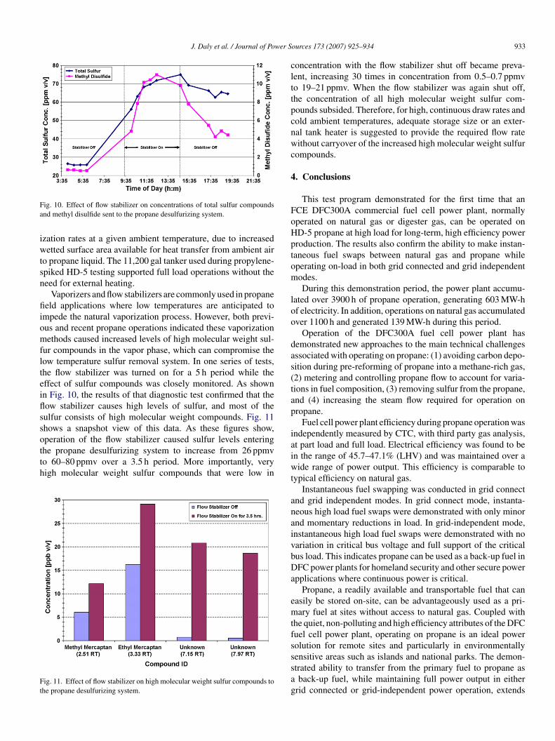
ig. 10. Effect of flow stabilizer on concentrations of total sulfur compoundsnd methyl disulfide sent to the propane desulfurizing system.
zation rates at a given ambient temperature, due to increasedetted surface area available for heat transfer from ambient air
o propane liquid. The 11,200 gal tanker used during propylene-piked HD-5 testing supported full load operations without theeed for external heating.
Vaporizers and flow stabilizers are commonly used in propaneeld applications where low temperatures are anticipated to
mpede the natural vaporization process. However, both previ-us and recent propane operations indicated these vaporizationethods caused increased levels of high molecular weight sul-
ur compounds in the vapor phase, which can compromise theow temperature sulfur removal system. In one series of tests,he flow stabilizer was turned on for a 5 h period while theffect of sulfur compounds was closely monitored. As shownn Fig. 10, the results of that diagnostic test confirmed that theow stabilizer causes high levels of sulfur, and most of theulfur consists of high molecular weight compounds. Fig. 11hows a snapshot view of this data. As these figures show,peration of the flow stabilizer caused sulfur levels entering
he propane desulfurizing system to increase from 26 ppmvo 60–80 ppmv over a 3.5 h period. More importantly, veryigh molecular weight sulfur compounds that were low inig. 11. Effect of flow stabilizer on high molecular weight sulfur compounds tohe propane desulfurizing system.
aiwt
anaivbDa
emtfsssag
ources 173 (2007) 925–934 933
oncentration with the flow stabilizer shut off became preva-ent, increasing 30 times in concentration from 0.5–0.7 ppmvo 19–21 ppmv. When the flow stabilizer was again shut off,he concentration of all high molecular weight sulfur com-ounds subsided. Therefore, for high, continuous draw rates andold ambient temperatures, adequate storage size or an exter-al tank heater is suggested to provide the required flow rateithout carryover of the increased high molecular weight sulfur
ompounds.
. Conclusions
This test program demonstrated for the first time that anCE DFC300A commercial fuel cell power plant, normallyperated on natural gas or digester gas, can be operated onD-5 propane at high load for long-term, high efficiency powerroduction. The results also confirm the ability to make instan-aneous fuel swaps between natural gas and propane whileperating on-load in both grid connected and grid independentodes.During this demonstration period, the power plant accumu-
ated over 3900 h of propane operation, generating 603 MW-hf electricity. In addition, operations on natural gas accumulatedver 1100 h and generated 139 MW-h during this period.
Operation of the DFC300A fuel cell power plant hasemonstrated new approaches to the main technical challengesssociated with operating on propane: (1) avoiding carbon depo-ition during pre-reforming of propane into a methane-rich gas,2) metering and controlling propane flow to account for varia-ions in fuel composition, (3) removing sulfur from the propane,nd (4) increasing the steam flow required for operation onropane.
Fuel cell power plant efficiency during propane operation wasndependently measured by CTC, with third party gas analysis,t part load and full load. Electrical efficiency was found to ben the range of 45.7–47.1% (LHV) and was maintained over aide range of power output. This efficiency is comparable to
ypical efficiency on natural gas.Instantaneous fuel swapping was conducted in grid connect
nd grid independent modes. In grid connect mode, instanta-eous high load fuel swaps were demonstrated with only minornd momentary reductions in load. In grid-independent mode,nstantaneous high load fuel swaps were demonstrated with noariation in critical bus voltage and full support of the criticalus load. This indicates propane can be used as a back-up fuel inFC power plants for homeland security and other secure power
pplications where continuous power is critical.Propane, a readily available and transportable fuel that can
asily be stored on-site, can be advantageously used as a pri-ary fuel at sites without access to natural gas. Coupled with
he quiet, non-polluting and high efficiency attributes of the DFCuel cell power plant, operating on propane is an ideal powerolution for remote sites and particularly in environmentally
ensitive areas such as islands and national parks. The demon-trated ability to transfer from the primary fuel to propane asback-up fuel, while maintaining full power output in eitherrid connected or grid-independent power operation, extends

9 wer S
tapethTtp
A
EocC
R
[[
[[
[
[
G
AAB◦CCcCCCCCCdDDeE◦FFGgHHHKkLMMO
34 J. Daly et al. / Journal of Po
he flexibility of the DFC power plant to provide secure powerpplications such as military installations, data centers, and hos-itals. The notion of dual fuel operation is part of the rapidvolution of fuel cells as a replacement for conventional elec-ric power where high efficiency, increased reliability, reducedarmful emissions, and lower noise levels are key requirements.his technology will continue to evolve and serve the mili-
ary and commercial markets demanding secure and reliableower.
cknowledgements
Funding for this project was provided by the U.S. ArmyRDC–CERL. The Department of Defense’s (DoD) FCTec isperated by CTC under contract no. DACA42-02-2-0001. CTConducted this work jointly with FCE for the ERDC–CERL Fuelell Technology Program.
eferences
[1] A.J. Appleby, Aerosp. Electron. Syst. Mag. IEEE 6 (12) (1991) 49–55.[2] Army Energy and Water Campaign Plan for Installations, Department of
the Army, August 2006, p. 52. http://army-energy.hqda.pentagon.mil/docs/campaign plan 01 08 06.pdf.
[3] P. Varbanov, et al., J. Fuel Cell Sci. Technol. 3 (4) (2006) 375–383.[4] Fuel Cell Energy DFC300A Fuel Cell Combined Heat and Power Test
Report. Submitted to the U.S. Army Engineer Research and DevelopmentCenter, Construction Engineering Research Laboratory by ConcurrentTechnologies Corporation, December 2, 2005.
[5] Final Technical Progress Report, submitted to U.S. Department of EnergyNational Energy Technology Laboratory, Submitted by FuelCell EnergyInc., March 2005.
[6] D. Brdar, C. Bentley, M. Farooque, P. Oei,T. Rauseo. 2006 Fuel Cell Sem-inar, Abstract 84, November 16, 2006.
[7] R. Peltier, Power 150 (2006).[8] US DOE/NETL, Fuel Cell Handbook, 5th ed., EG&G, Parsons Inc., SAIC,
2000.[9] D. Brdar, M. Farooque, Fuel Cell Rev. 2 (5) (2005).
10] M. Farooque, H.C. Maru, J. Power Sources 160 (2006) 827–834.11] ASTM D 1835, Standard Specification for Liquefied Petroleum (LP) Gases,ASTM International, West Conshohocken, PA, USA.12] W. Wang, et al., Chem. Eng. J. 129 (2007) 11–19.13] L.F. Brown, Int. J. Hydrogen Energy 26 (2001) 381–397.
PPppV
ources 173 (2007) 925–934
14] Fuel Cell Power Systems, Performance Test Codes (ASME PTC 50-2002),The American Society of Mechanical Engineers, Three Park Avenue, NewYork, NY, November 29, 2002.
15] Final Report, prepared for U.S. EPA by King County and CH2MHill, April2007.
lossary
C: alternating currentSME: American Society of Mechanical Engineerstu: British thermal unit.C: degree centigradeCB: critical customer busERL: Construction Engineering Research Laboratoryfm: cubic feet per minuteH4: methane
3H8: propaneO: carbon monoxideO2: carbon dioxideO3
2−: carbonate ionsTC: Concurrent Technologies CorporationB: decibelFC®: Direct Fuel Cell®
oD: Department of Defense−: electronsRDC: Engineer Research and Development CenterF: degree FahrenheitCE: FuelCell Energy Inc.CTec: Fuel Cell Test and Evaluation CenterC: gas chromatographph: gallons per hour
2: hydrogen
2O: waterz: hertzVA: kilovolt ampereW: kilowattHV: lower heating valueCFC: molten carbonate fuel cellW-h: megawatt-hours
2: oxygenAFC: phosphoric acid fuel cell
EMFC: polymer electrolyte membrane fuel cellpmv: parts per million volumesig: pounds per square inch gauge: volt


![Molten Carbonate Fuel Cells for SAGD - CESAR · [6] R. Remick and D. Wheeler, "Molten Carbonate and PhosphoricAcid Stationary Fuel Cells: Overview and Gap Analysis," National Renewable](https://img.pdfslide.us/doc/110x75/5e61d8083724b648a77118f9/molten-carbonate-fuel-cells-for-sagd-cesar-6-r-remick-and-d-wheeler-molten.jpg)