Embed Size (px)
Citation preview
Mold bases
Basic Molds are a class of molds that, while can be very basic in application, are molds that have no Action incorporated into the mold to produce a part.
The parting line can be planer, non-uniform, angled, and may be complex.
Basic Mold Design
Before an Injection Mold Design can be started the following criteria must be known, to enable a proper design.
Part Size Function Acceptable Witness Marks for Parting Line, Method of Ejection, and Gate Material Type, and Processing Characteristics, Shrink, Draft Requirements Production Required, Time Frame and Life of Mold Tolerance Considerations Runner Finish Specification, Data Inserts
Machine Type Knock out Bar, Size and spacing Tonnage Platen size Shot size Locating Ring hole size Nozzle Spherical Radius, and 'O' Dimension Coolant Connector Type and Size
Processing Capacity Study Cycle time Number of Cavities Required Per Mold Possible Types of Mold bases Number of Molds to be Ordered, Spare Cavity Steels Required
General What is the Timing of the Design/Mold Delivery?
If the above is known or specified, a mold design can be started.
A GENERAL APPROACH MAY FOLLOW THE FOLLOWING STEPS:(INJECTION MOLD DESIGN REQUIRES SYNTHESIS OF MANY
REQUIREMENTS AT THE SAME TIME )
Start at the part and work your way out.Determine the best gate location. CAE (Flow Analysis) is a superior tool to help determine a proper gate location.
Determine the appropriate Possible Parting Lines.
The location of an acceptable parting line will provide for proper ejection of the part from the mold.
A correct parting line will ensure that the part 'Sticks' to the ejection (core) side of the mold.
Determine a Runner Layout that suits the number of cavities needed for the mold and incorporate Cold Slug Wells into the layout.
The next three items need to be 'Juggled" at the same time. Ejection, Coolant lines, Cavity steel sizes.
Determine Cavity steel sizes (you should have and idea of cooling layout too, at this point). Will coolant holes be needed in the cavity steels?
Determine the Ejection method, and location of the ejector contact area.
Determine Cooling Line location per coolant line placement rules.
Select a possible Mold base (may change later) that suits the design requirements (Ejection travel, coolant connectors counterbored, general size. Make sure that the Knock-out bars will actuate the ejection system.
Determine the number and size of Support Pillars needed for the mold. Extend the Ejector Bar if Necessary
Select a Sprue Bushing, and Locating Ring based of the Machine specified for producing parts.
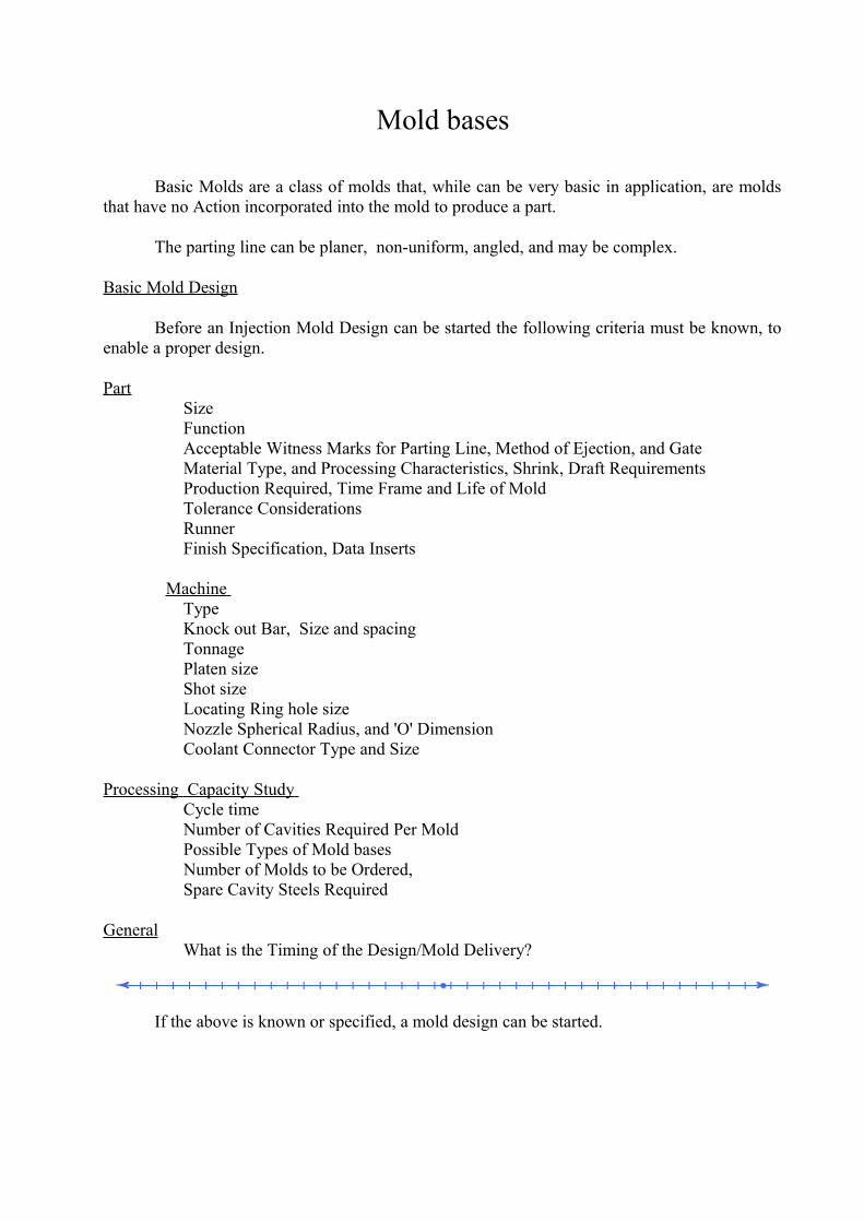
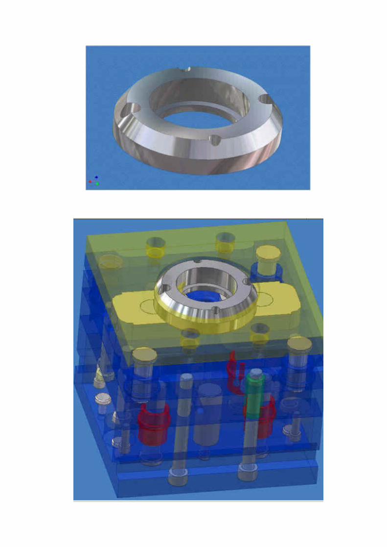
Locating Ring
Function:
The function of a Locating Ring is to Align the Mold Base to the Stationary Platen side of the Press. The Sprue Bushing is also located via a hole in the Locating Ring.
The Locating Ring is located and fastened into the Top Clamp Plate (TCP) via counterbored hole.
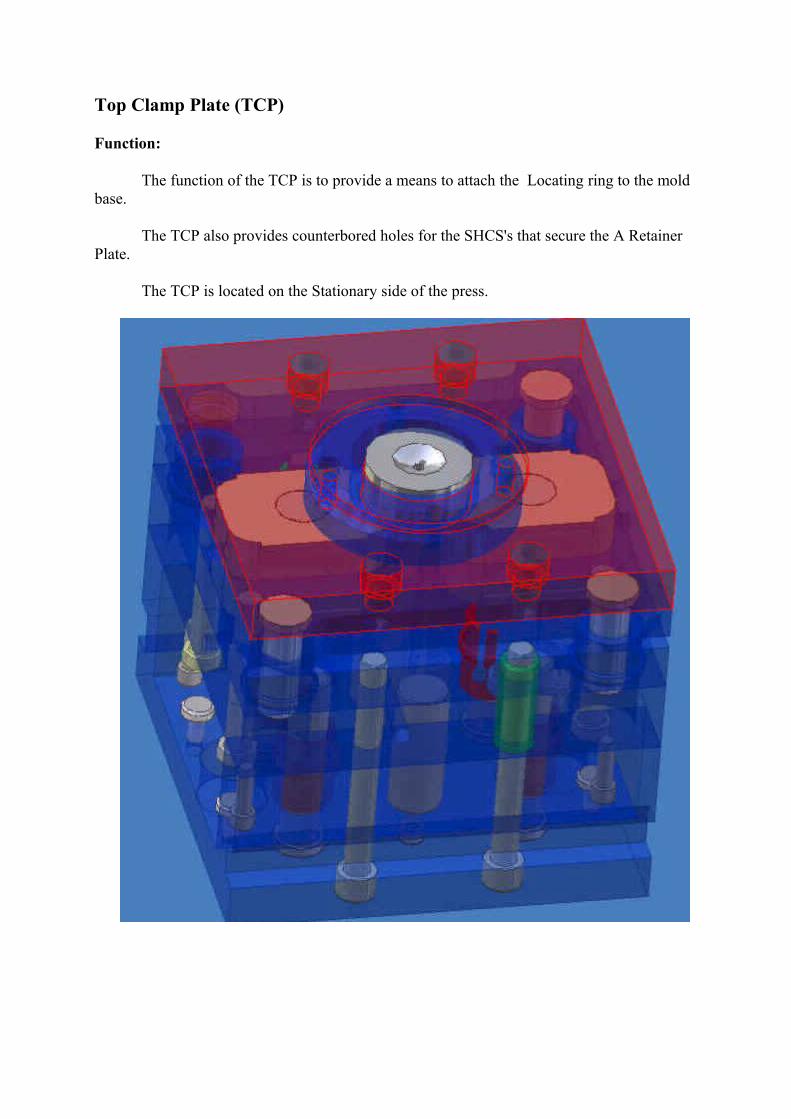
Top Clamp Plate (TCP)
Function:
The function of the TCP is to provide a means to attach the Locating ring to the mold base.
The TCP also provides counterbored holes for the SHCS's that secure the A Retainer Plate.
The TCP is located on the Stationary side of the press.
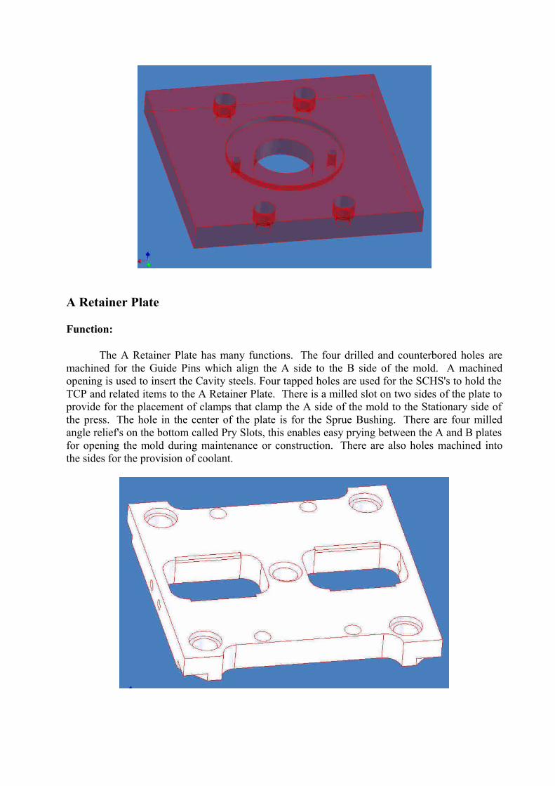
A Retainer Plate
Function:
The A Retainer Plate has many functions. The four drilled and counterbored holes are machined for the Guide Pins which align the A side to the B side of the mold. A machined opening is used to insert the Cavity steels. Four tapped holes are used for the SCHS's to hold the TCP and related items to the A Retainer Plate. There is a milled slot on two sides of the plate to provide for the placement of clamps that clamp the A side of the mold to the Stationary side of the press. The hole in the center of the plate is for the Sprue Bushing. There are four milled angle relief's on the bottom called Pry Slots, this enables easy prying between the A and B plates for opening the mold during maintenance or construction. There are also holes machined into the sides for the provision of coolant.
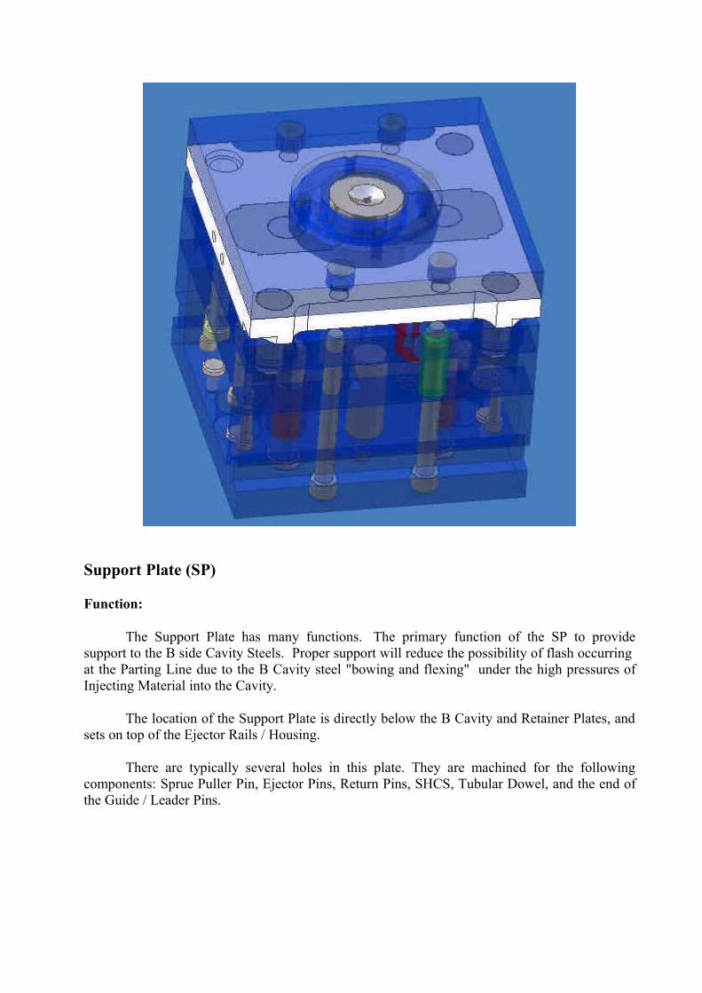
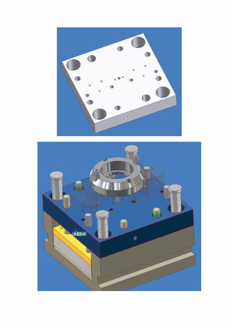
Support Plate (SP)
Function:
The Support Plate has many functions. The primary function of the SP to provide support to the B side Cavity Steels. Proper support will reduce the possibility of flash occurring at the Parting Line due to the B Cavity steel "bowing and flexing" under the high pressures of Injecting Material into the Cavity.
The location of the Support Plate is directly below the B Cavity and Retainer Plates, and sets on top of the Ejector Rails / Housing.
There are typically several holes in this plate. They are machined for the following components: Sprue Puller Pin, Ejector Pins, Return Pins, SHCS, Tubular Dowel, and the end of the Guide / Leader Pins.
Cavity Steels
Function:
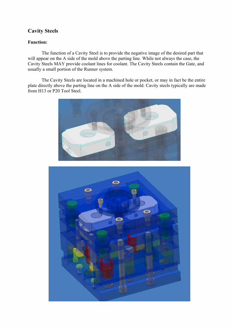
The function of a Cavity Steel is to provide the negative image of the desired part that will appear on the A side of the mold above the parting line. While not always the case, the Cavity Steels MAY provide coolant lines for coolant. The Cavity Steels contain the Gate, and usually a small portion of the Runner system.
The Cavity Steels are located in a machined hole or pocket, or may in fact be the entire plate directly above the parting line on the A side of the mold. Cavity steels typically are made from H13 or P20 Tool Steel.
Sprue Bushing
Function:
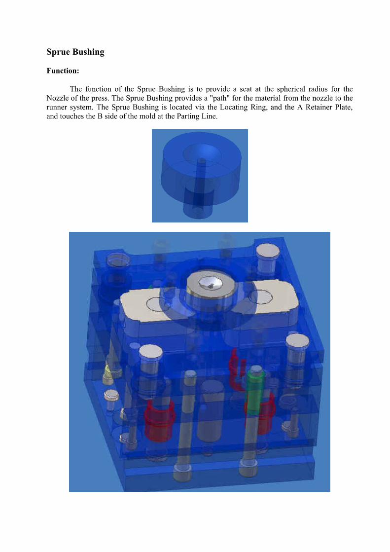
The function of the Sprue Bushing is to provide a seat at the spherical radius for the Nozzle of the press. The Sprue Bushing provides a "path" for the material from the nozzle to the runner system. The Sprue Bushing is located via the Locating Ring, and the A Retainer Plate, and touches the B side of the mold at the Parting Line.
Sprue Puller Pin
Function:
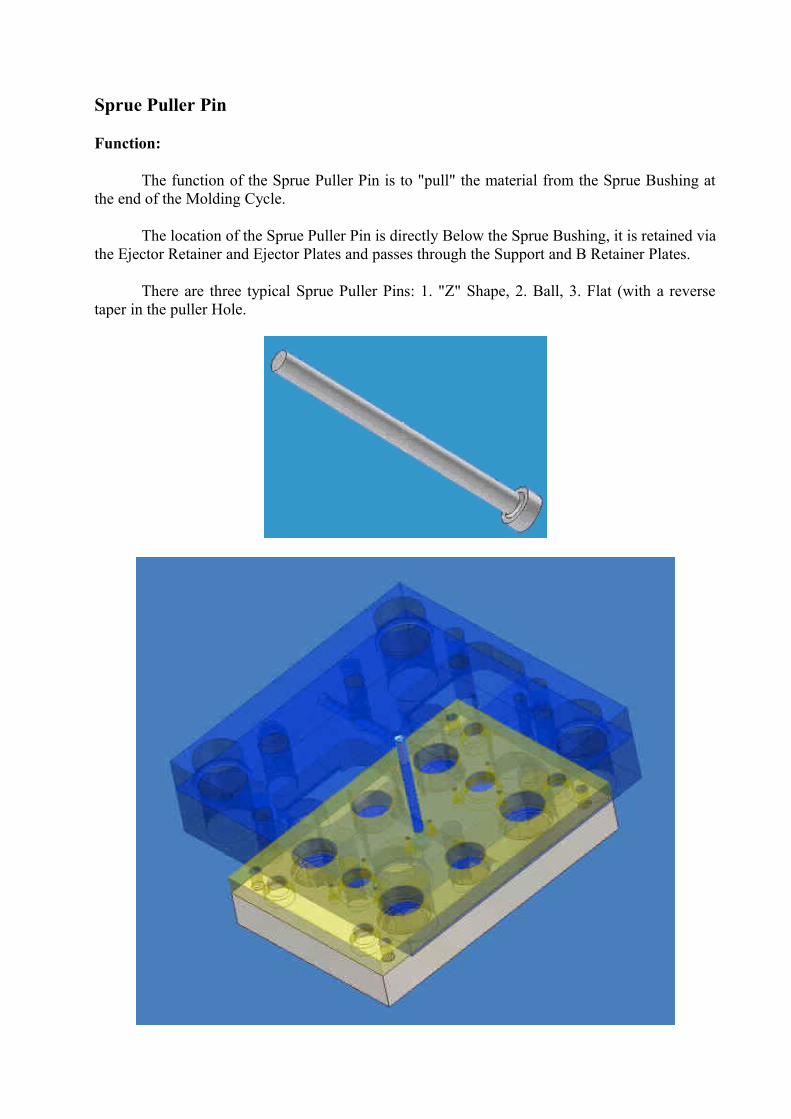
The function of the Sprue Puller Pin is to "pull" the material from the Sprue Bushing at the end of the Molding Cycle.
The location of the Sprue Puller Pin is directly Below the Sprue Bushing, it is retained via the Ejector Retainer and Ejector Plates and passes through the Support and B Retainer Plates.
There are three typical Sprue Puller Pins: 1. "Z" Shape, 2. Ball, 3. Flat (with a reverse taper in the puller Hole.
Guided Ejector Pin and Bushing
Function:
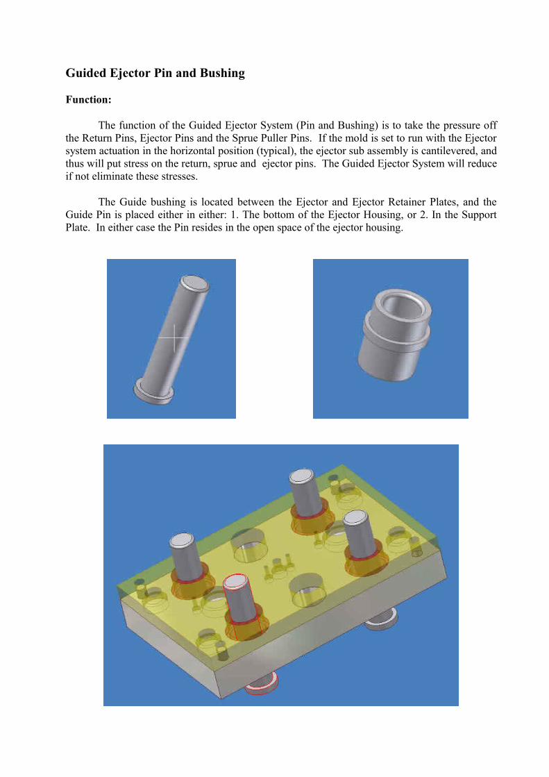
The function of the Guided Ejector System (Pin and Bushing) is to take the pressure off the Return Pins, Ejector Pins and the Sprue Puller Pins. If the mold is set to run with the Ejector system actuation in the horizontal position (typical), the ejector sub assembly is cantilevered, and thus will put stress on the return, sprue and ejector pins. The Guided Ejector System will reduce if not eliminate these stresses.
The Guide bushing is located between the Ejector and Ejector Retainer Plates, and the Guide Pin is placed either in either: 1. The bottom of the Ejector Housing, or 2. In the Support Plate. In either case the Pin resides in the open space of the ejector housing.
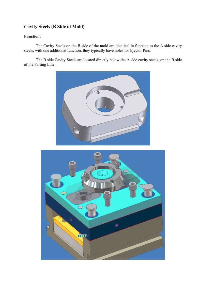
Cavity Steels (B Side of Mold)
Function:
The Cavity Steels on the B side of the mold are identical in function to the A side cavity steels, with one additional function, they typically have holes for Ejector Pins.
The B side Cavity Steels are located directly below the A side cavity steels, on the B side of the Parting Line.
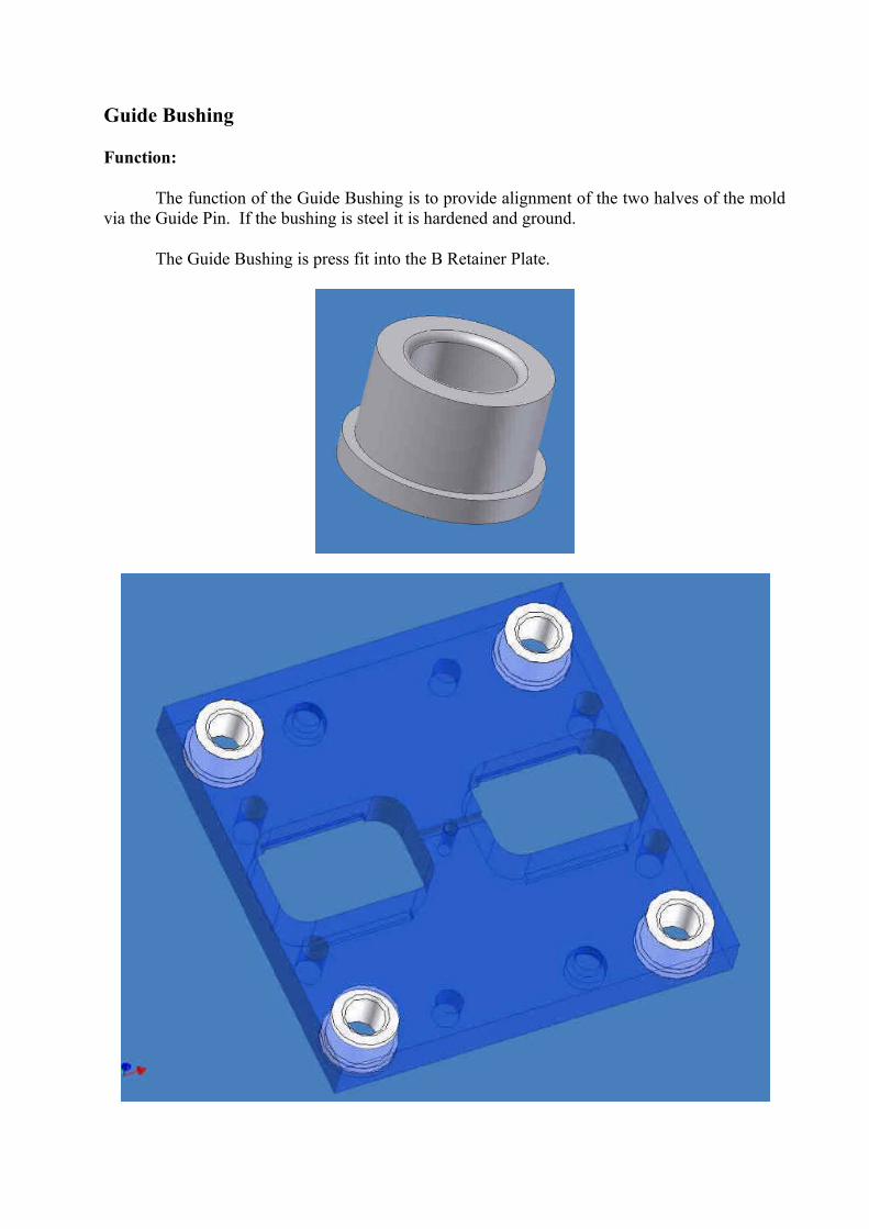
Guide Bushing
Function:
The function of the Guide Bushing is to provide alignment of the two halves of the mold via the Guide Pin. If the bushing is steel it is hardened and ground.
The Guide Bushing is press fit into the B Retainer Plate.
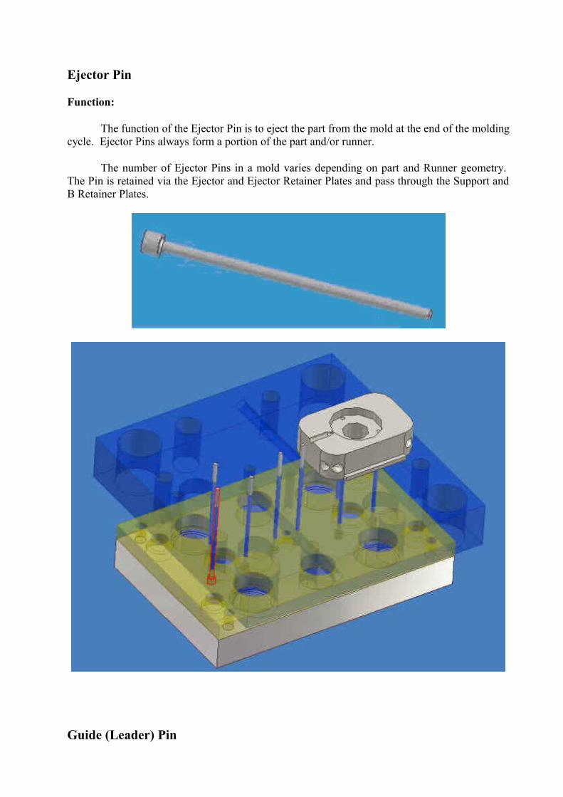
Ejector Pin
Function:
The function of the Ejector Pin is to eject the part from the mold at the end of the molding cycle. Ejector Pins always form a portion of the part and/or runner.
The number of Ejector Pins in a mold varies depending on part and Runner geometry. The Pin is retained via the Ejector and Ejector Retainer Plates and pass through the Support and B Retainer Plates.
Guide (Leader) Pin
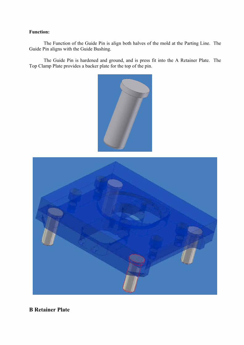
Function:
The Function of the Guide Pin is align both halves of the mold at the Parting Line. The Guide Pin aligns with the Guide Bushing.
The Guide Pin is hardened and ground, and is press fit into the A Retainer Plate. The Top Clamp Plate provides a backer plate for the top of the pin.
B Retainer Plate
Function:
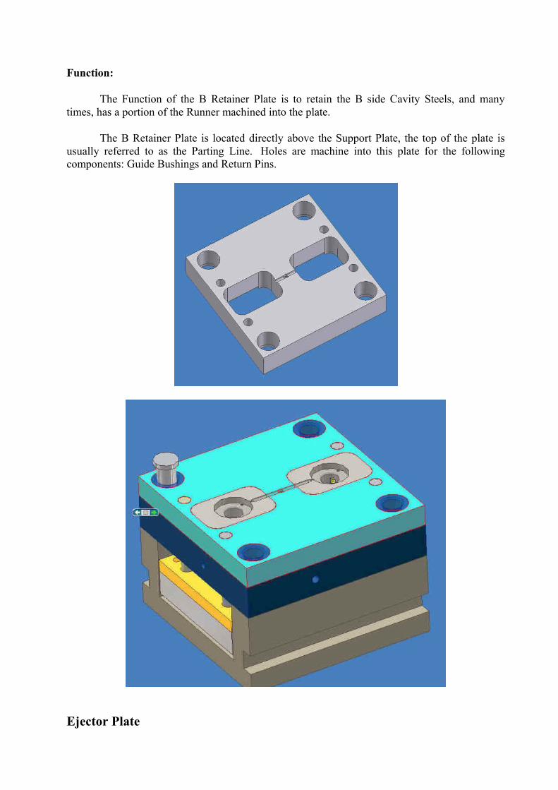
The Function of the B Retainer Plate is to retain the B side Cavity Steels, and many times, has a portion of the Runner machined into the plate.
The B Retainer Plate is located directly above the Support Plate, the top of the plate is usually referred to as the Parting Line. Holes are machine into this plate for the following components: Guide Bushings and Return Pins.
Ejector Plate
Function:
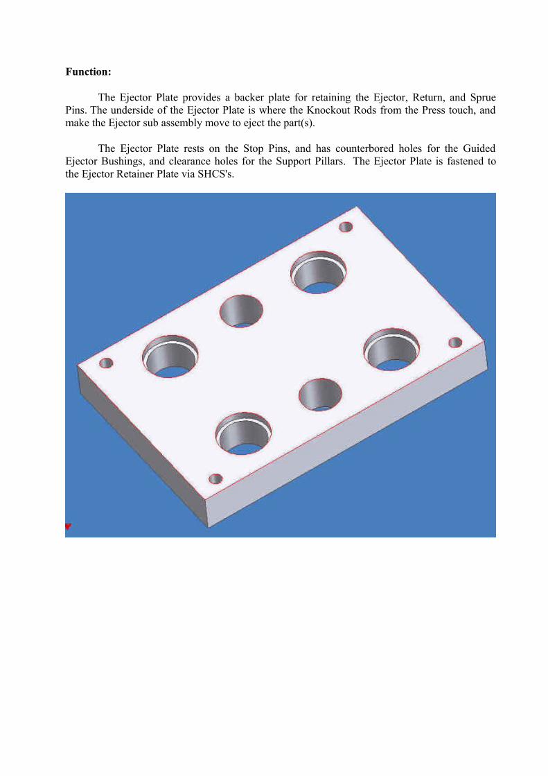
The Ejector Plate provides a backer plate for retaining the Ejector, Return, and Sprue Pins. The underside of the Ejector Plate is where the Knockout Rods from the Press touch, and make the Ejector sub assembly move to eject the part(s).
The Ejector Plate rests on the Stop Pins, and has counterbored holes for the Guided Ejector Bushings, and clearance holes for the Support Pillars. The Ejector Plate is fastened to the Ejector Retainer Plate via SHCS's.
Ejector Housing
Function:
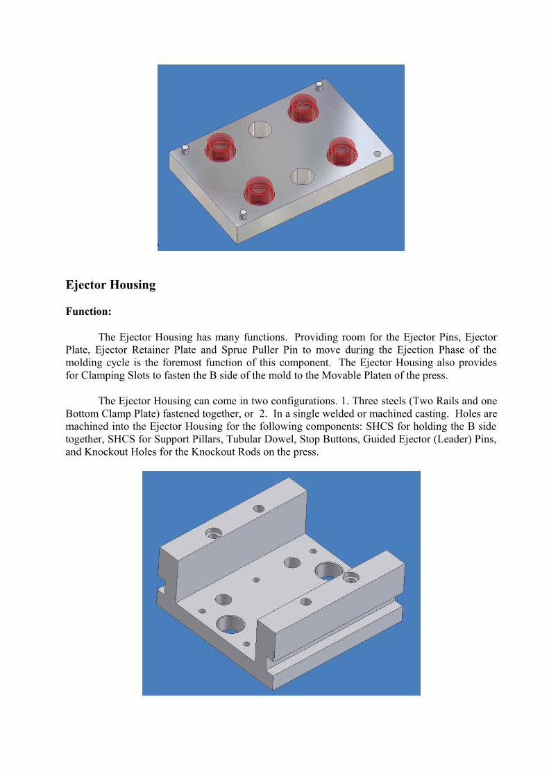
The Ejector Housing has many functions. Providing room for the Ejector Pins, Ejector Plate, Ejector Retainer Plate and Sprue Puller Pin to move during the Ejection Phase of the molding cycle is the foremost function of this component. The Ejector Housing also provides for Clamping Slots to fasten the B side of the mold to the Movable Platen of the press.
The Ejector Housing can come in two configurations. 1. Three steels (Two Rails and one Bottom Clamp Plate) fastened together, or 2. In a single welded or machined casting. Holes are machined into the Ejector Housing for the following components: SHCS for holding the B side together, SHCS for Support Pillars, Tubular Dowel, Stop Buttons, Guided Ejector (Leader) Pins, and Knockout Holes for the Knockout Rods on the press.
Ejector Retainer Plate
Function:
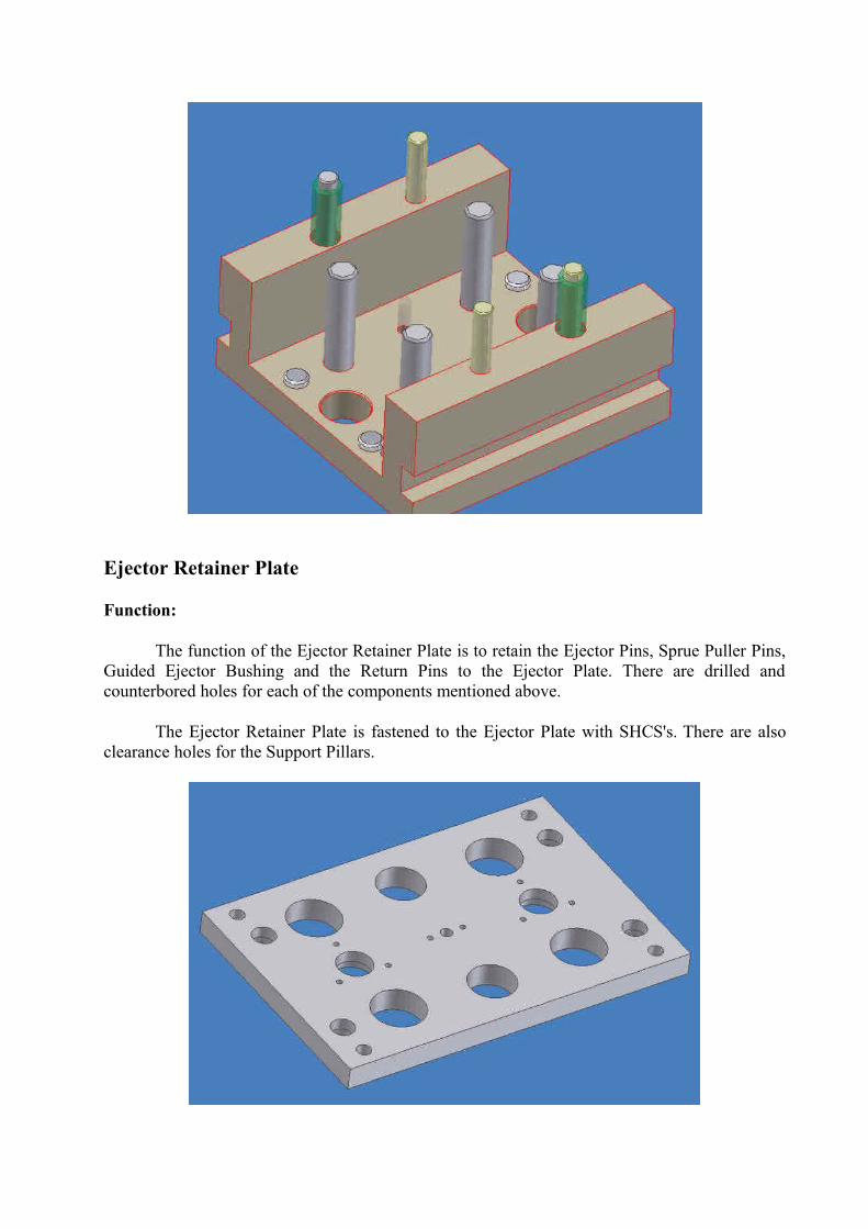
The function of the Ejector Retainer Plate is to retain the Ejector Pins, Sprue Puller Pins, Guided Ejector Bushing and the Return Pins to the Ejector Plate. There are drilled and counterbored holes for each of the components mentioned above.
The Ejector Retainer Plate is fastened to the Ejector Plate with SHCS's. There are also clearance holes for the Support Pillars.
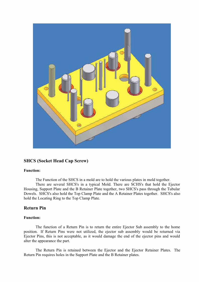
SHCS (Socket Head Cap Screw)
Function:
The Function of the SHCS in a mold are to hold the various plates in mold together.There are several SHCS's in a typical Mold. There are SCHS's that hold the Ejector
Housing, Support Plate and the B Retainer Plate together, two SHCS's pass through the Tubular Dowels. SHCS's also hold the Top Clamp Plate and the A Retainer Plates together. SHCS's also hold the Locating Ring to the Top Clamp Plate.
Return Pin
Function:
The function of a Return Pin is to return the entire Ejector Sub assembly to the home position. If Return Pins were not utilized, the ejector sub assembly would be returned via Ejector Pins, this is not acceptable, as it would damage the end of the ejector pins and would alter the appearance the part.
The Return Pin is retained between the Ejector and the Ejector Retainer Plates. The Return Pin requires holes in the Support Plate and the B Retainer plates.
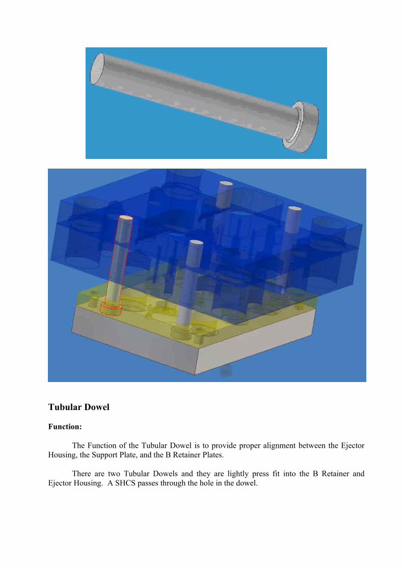
Tubular Dowel
Function:
The Function of the Tubular Dowel is to provide proper alignment between the Ejector Housing, the Support Plate, and the B Retainer Plates.
There are two Tubular Dowels and they are lightly press fit into the B Retainer and Ejector Housing. A SHCS passes through the hole in the dowel.
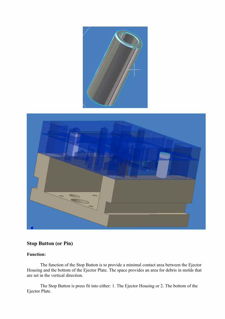
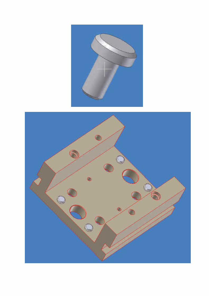
Stop Button (or Pin)
Function:
The function of the Stop Button is to provide a minimal contact area between the Ejector Housing and the bottom of the Ejector Plate. The space provides an area for debris in molds that are set in the vertical direction.
The Stop Button is press fit into either: 1. The Ejector Housing or 2. The bottom of the Ejector Plate.
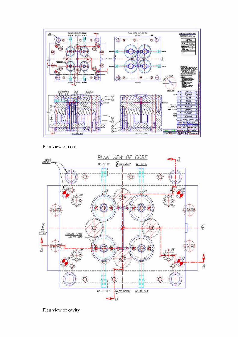
Plan view of core
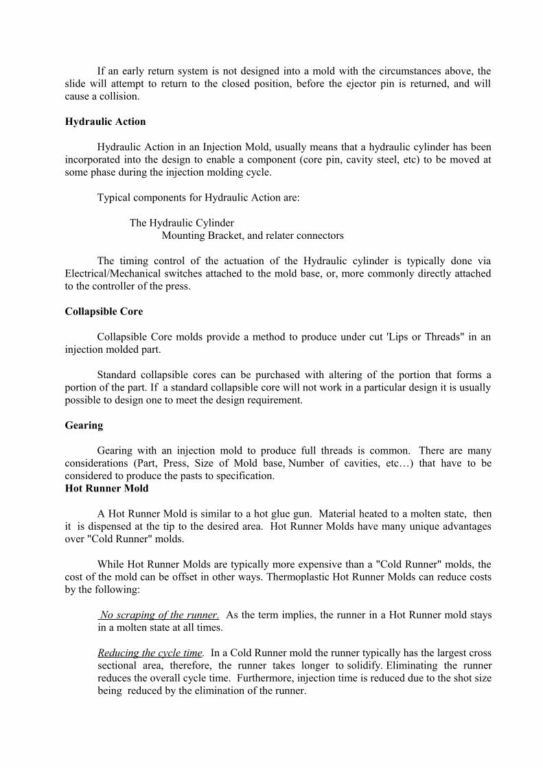
Plan view of cavity
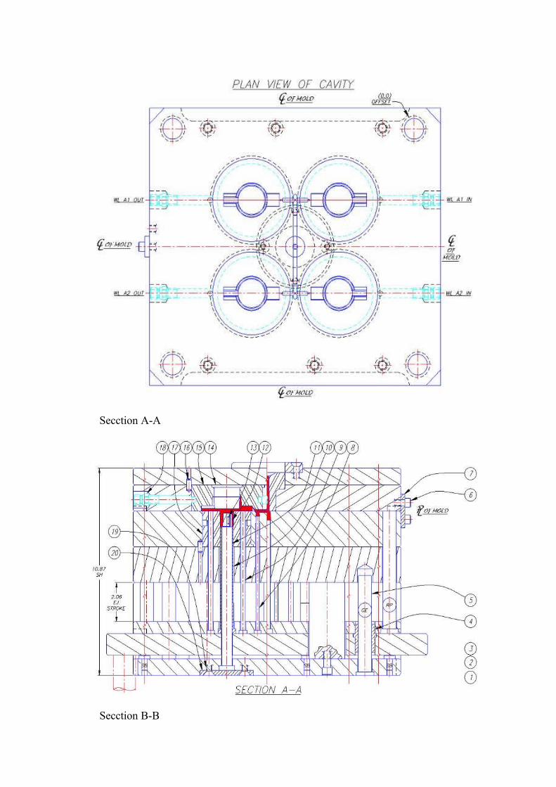
Secction A-A
Secction B-B
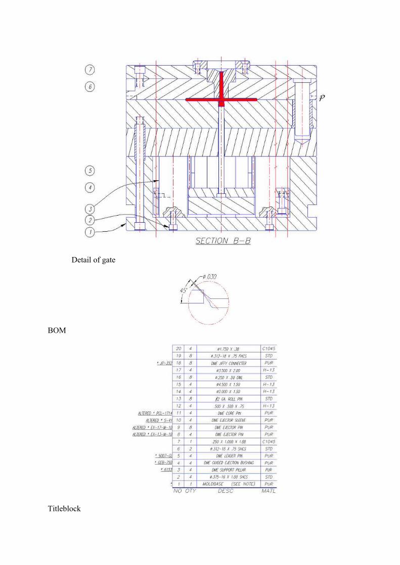
Detail of gate
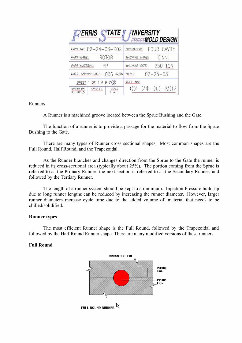
BOM
Titleblock
Runners
A Runner is a machined groove located between the Sprue Bushing and the Gate.
The function of a runner is to provide a passage for the material to flow from the Sprue Bushing to the Gate.
There are many types of Runner cross sectional shapes. Most common shapes are the Full Round, Half Round, and the Trapezoidal.
As the Runner branches and changes direction from the Sprue to the Gate the runner is reduced in its cross-sectional area (typically about 25%). The portion coming from the Sprue is referred to as the Primary Runner, the next section is referred to as the Secondary Runner, and followed by the Tertiary Runner.
The length of a runner system should be kept to a minimum. Injection Pressure build-up due to long runner lengths can be reduced by increasing the runner diameter. However, larger runner diameters increase cycle time due to the added volume of material that needs to be chilled/solidified.
Runner types
The most efficient Runner shape is the Full Round, followed by the Trapezoidal and followed by the Half Round Runner shape. There are many modified versions of these runners.
Full Round
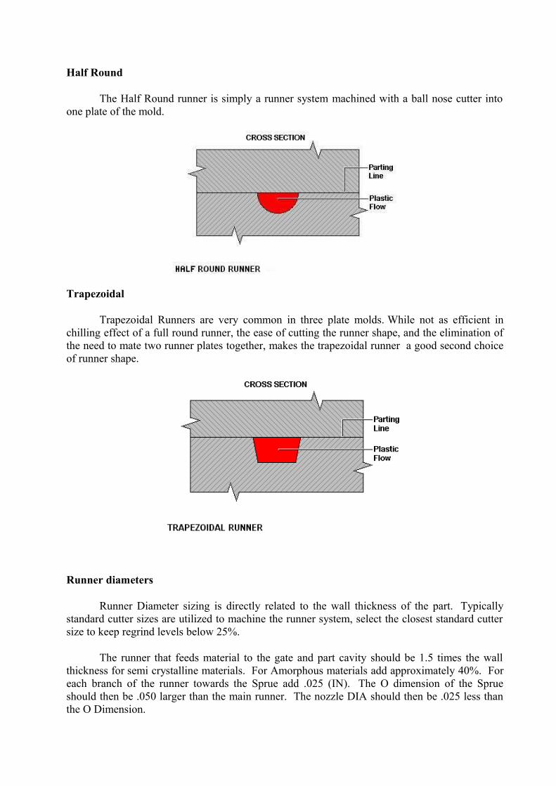
Half Round
The Half Round runner is simply a runner system machined with a ball nose cutter into one plate of the mold.
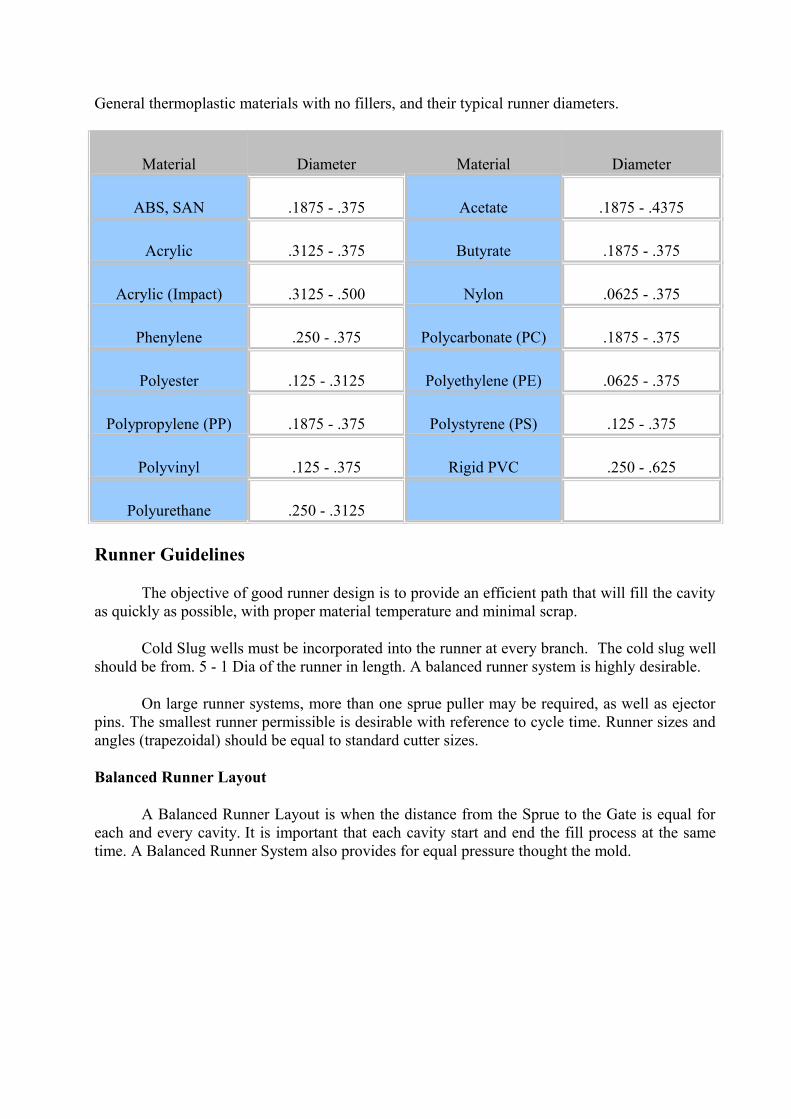
Trapezoidal
Trapezoidal Runners are very common in three plate molds. While not as efficient in chilling effect of a full round runner, the ease of cutting the runner shape, and the elimination of the need to mate two runner plates together, makes the trapezoidal runner a good second choice of runner shape.
Runner diameters
Runner Diameter sizing is directly related to the wall thickness of the part. Typically standard cutter sizes are utilized to machine the runner system, select the closest standard cutter size to keep regrind levels below 25%.
The runner that feeds material to the gate and part cavity should be 1.5 times the wall thickness for semi crystalline materials. For Amorphous materials add approximately 40%. For each branch of the runner towards the Sprue add .025 (IN). The O dimension of the Sprue should then be .050 larger than the main runner. The nozzle DIA should then be .025 less than the O Dimension.
General thermoplastic materials with no fillers, and their typical runner diameters.
Material Diameter Material Diameter
ABS, SAN .1875 - .375 Acetate .1875 - .4375
Acrylic .3125 - .375 Butyrate .1875 - .375
Acrylic (Impact) .3125 - .500 Nylon .0625 - .375
Phenylene .250 - .375 Polycarbonate (PC) .1875 - .375
Polyester .125 - .3125 Polyethylene (PE) .0625 - .375
Polypropylene (PP) .1875 - .375 Polystyrene (PS) .125 - .375
Polyvinyl .125 - .375 Rigid PVC .250 - .625
Polyurethane .250 - .3125
Runner Guidelines
The objective of good runner design is to provide an efficient path that will fill the cavity as quickly as possible, with proper material temperature and minimal scrap.
Cold Slug wells must be incorporated into the runner at every branch. The cold slug well should be from. 5 - 1 Dia of the runner in length. A balanced runner system is highly desirable.
On large runner systems, more than one sprue puller may be required, as well as ejector pins. The smallest runner permissible is desirable with reference to cycle time. Runner sizes and angles (trapezoidal) should be equal to standard cutter sizes.
Balanced Runner Layout
A Balanced Runner Layout is when the distance from the Sprue to the Gate is equal for each and every cavity. It is important that each cavity start and end the fill process at the same time. A Balanced Runner System also provides for equal pressure thought the mold.
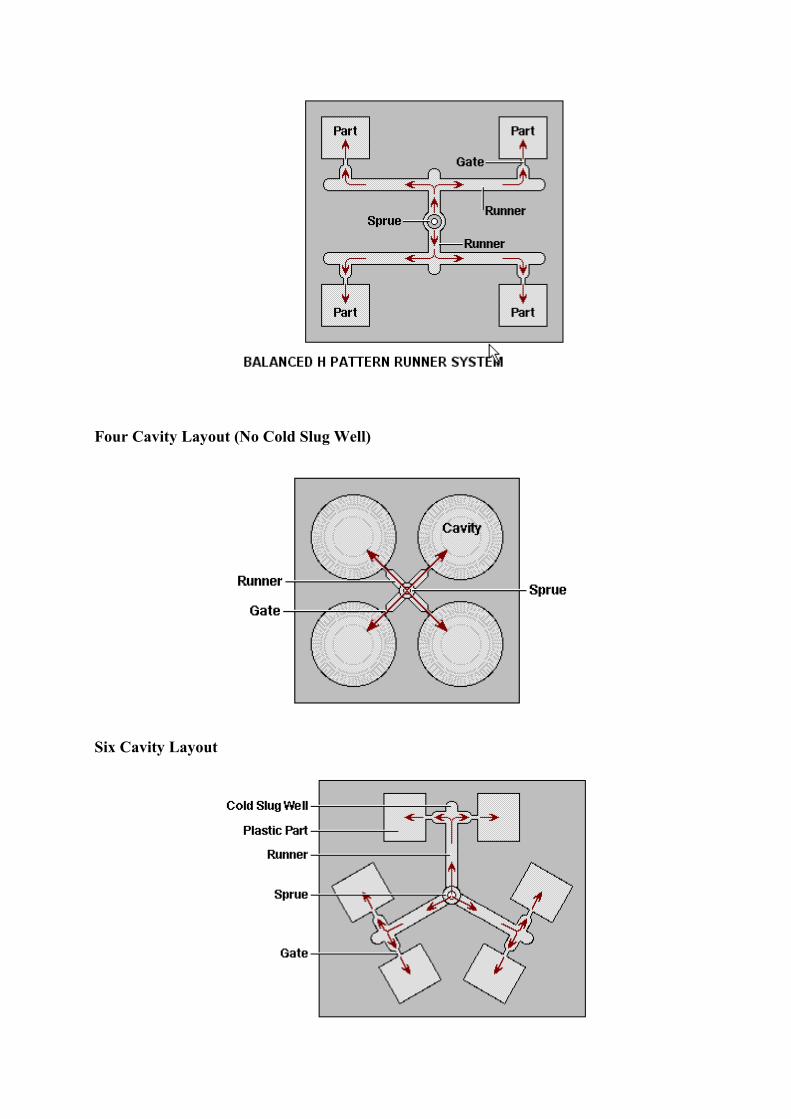
Four Cavity Layout (No Cold Slug Well)
Six Cavity Layout
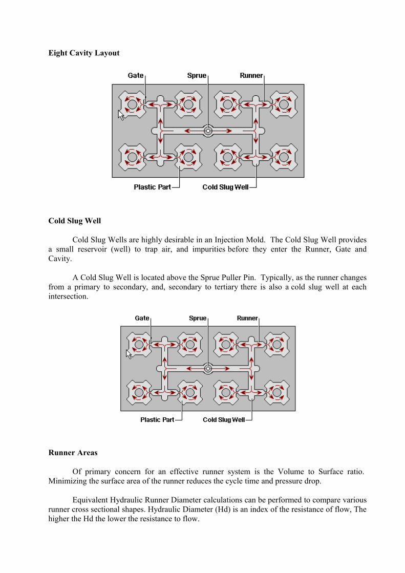
Eight Cavity Layout
Cold Slug Well
Cold Slug Wells are highly desirable in an Injection Mold. The Cold Slug Well provides a small reservoir (well) to trap air, and impurities before they enter the Runner, Gate and Cavity.
A Cold Slug Well is located above the Sprue Puller Pin. Typically, as the runner changes from a primary to secondary, and, secondary to tertiary there is also a cold slug well at each intersection.
Runner Areas
Of primary concern for an effective runner system is the Volume to Surface ratio. Minimizing the surface area of the runner reduces the cycle time and pressure drop.
Equivalent Hydraulic Runner Diameter calculations can be performed to compare various runner cross sectional shapes. Hydraulic Diameter (Hd) is an index of the resistance of flow, The higher the Hd the lower the resistance to flow.
The formula: 4 A /P = Hd
where: A = cross sectional area P = perimeter Hd = Hydraulic Diameter
Cold Sprue
A standard Cold Sprue Bushing provides a means for the material to travel from the Machine Nozzle to the Runners.
The Nozzle end of the bushing has two important dimensions. One is the hole opening, it is referred to as the "O" dimension, and the other is the spherical radius that seats with the nozzle. The 'O' dimension should be 7/32R (.44 DIA) with 9/16R being used on very large molds. The spherical radius should be .75 SPHR, with .5 SPHR being used on some machines.
The hole inside the Sprue Bushing should taper at .50 or .56 TPF. The taper hole diameter at the Runner end of the bushing should be equal to, or be slightly larger than the runner diameter. A radius of approx. .03-.06 should be placed at the taper and runner intersection.
Below the Sprue Bushing should be a provision for a Sprue Puller mechanism. There are three common types of Sprue Pullers, and they are typically .25 below the parting line, which functions as a cold slug well.
Reverse taper well 'Z' cut on Sprue Puller Pin Bulb machined on the end of the Sprue Puller Pin.
Gussets are sometimes cut into the Sprue Bushing to help reduce the cycle time.
Hot runner
A Hot Runner Mold is similar to a hot glue gun. Material is heated to a molten state, then it is dispensed at the tip to the desired area. Parts can be small single gated, or large and multi-gated. Hot Runner Molds have many unique advantages over "Cold Runner" molds.
While Hot Runner Molds are typically more expensive than "Cold Runner" molds, the cost of the mold can be offset in other ways. Thermoplastic Hot Runner Molds can reduce costs due to:
No scraping of the runner. As the term implies, the runner in a Hot Runner mold stays in a molten state at all times (no regrind).
Reducing the cycle time. In a Cold Runner mold the runner typically has the largest cross sectional area, therefore, the runner takes longer to solidify. Eliminating the runner reduces the overall cycle time. Furthermore, injection time is reduced due to the shot size being reduced by the elimination of the runner.
Hot Runner Molds have the ability to improve both part and mold design with flexibility of gating locations, which provides options for cavity orientation. Pressure drops are greatly
reduced due to the balanced melt flow as the temperature is consistent from the machine nozzle to the gate.
Precise material temperature control is critical to successful Hot Runner processing.
Gates
A Gate is a small area between the runner and the part cavity. The type, size and location of a Gate in an injection mold is critical to efficiently producing quality parts.
The type of gate selected depends on many factors including: Gate witness marks, Material Type, Filler used (if any), Tooling Costs, Scrap Allowance, and the Mold Plates used among others.
A single gate per cavity is desired, however, part size and the material used may require multiple gates to be used.
Locate the gate in an inconspicuous location of the part if possible. The Gate location should be at the thickest wall of the part (flow from thick,to thin) and the thickness of the gate should be approximately two thirds the size of the wall.
The gate location and the surrounding area is also the highest area of stress in the final part. Do not position the gate at a location that part function indicates bending or impact strength is required.
There are two general categories of gates:
1. Automatic De-gating Automatic de-gating includes Sub gates and 3-Plate Pin gates 2. Manual De-gating All others generally fall into the Manual de-gating category.
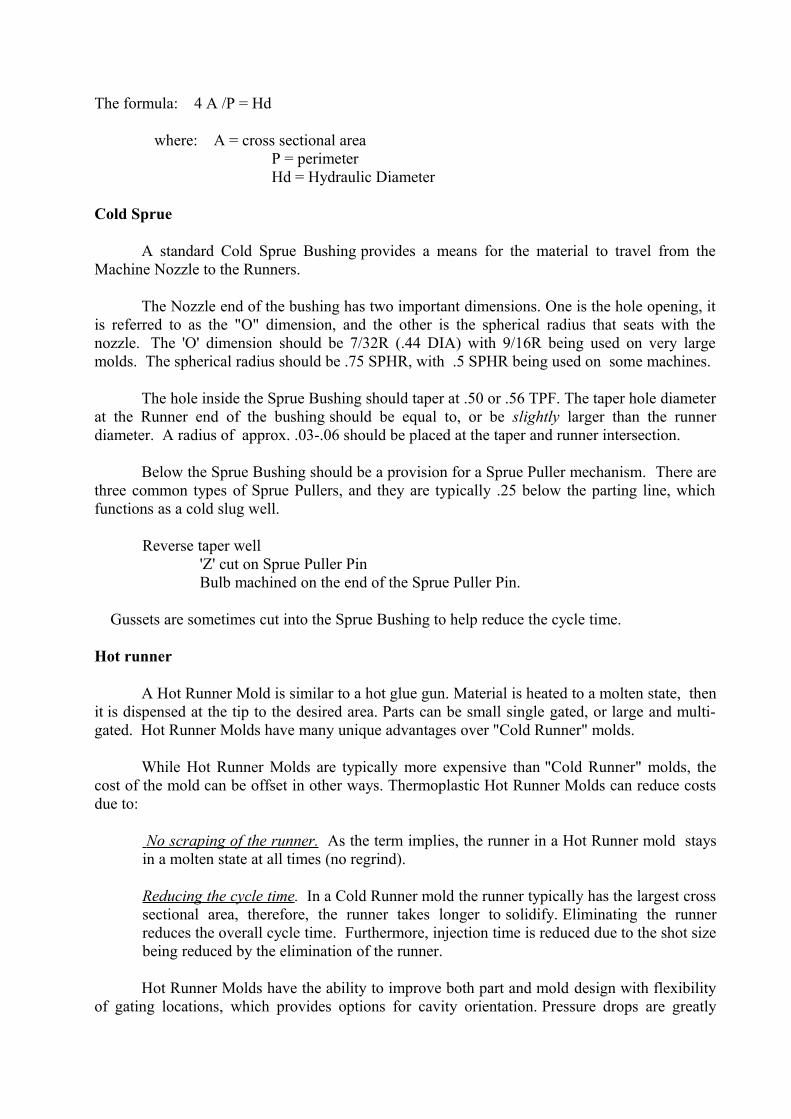
Edge gate
Edge Gates are the most commonly used of all gating options. The height of the gate should equal 75-100% of the wall thickness up to .125 in. The width should equal 2 times the depth. as it would appear in a mold.
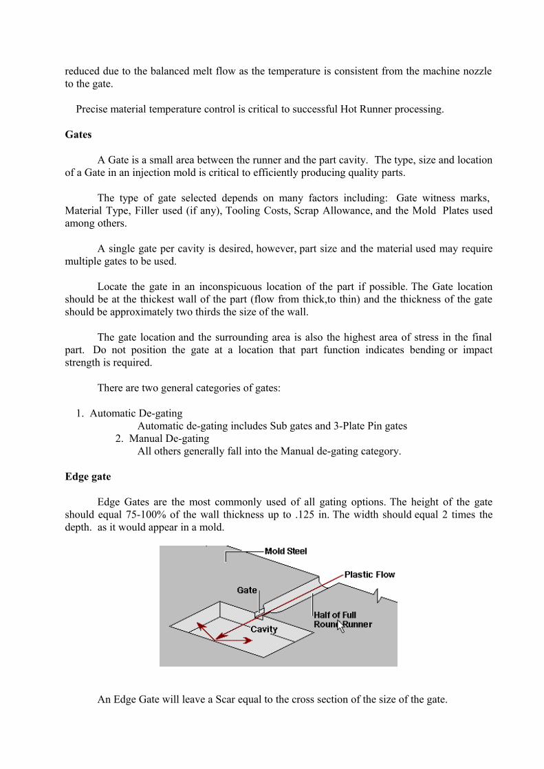
An Edge Gate will leave a Scar equal to the cross section of the size of the gate.
Fan Gate
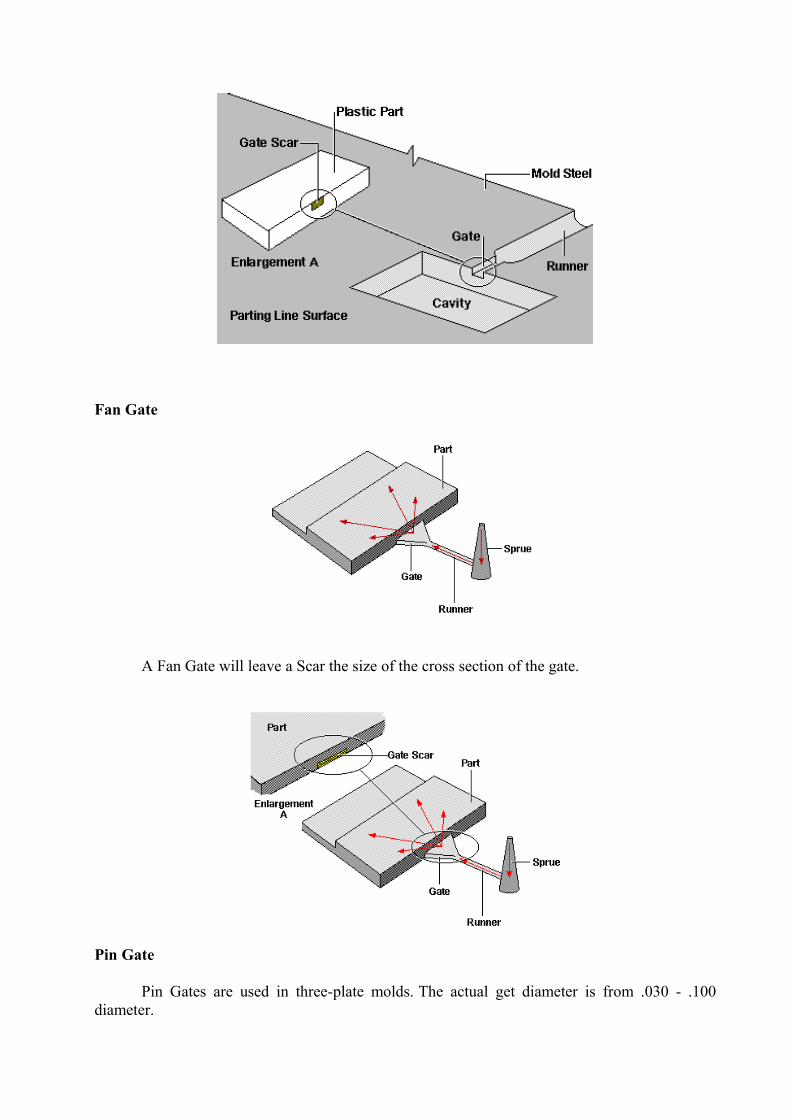
A Fan Gate will leave a Scar the size of the cross section of the gate.
Pin Gate
Pin Gates are used in three-plate molds. The actual get diameter is from .030 - .100 diameter.
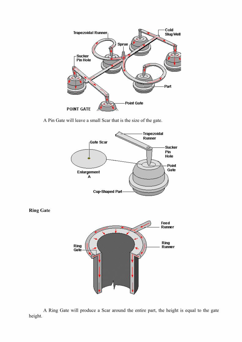
A Pin Gate will leave a small Scar that is the size of the gate.
Ring Gate
A Ring Gate will produce a Scar around the entire part, the height is equal to the gate height.
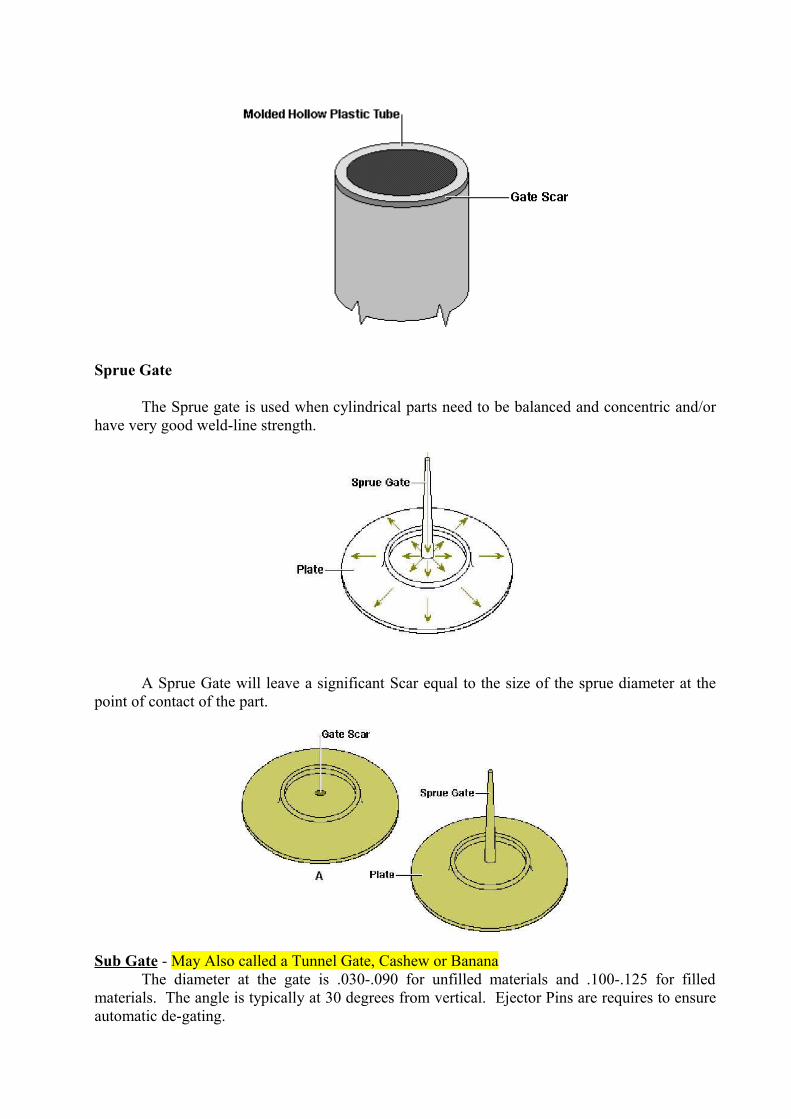
Sprue Gate
The Sprue gate is used when cylindrical parts need to be balanced and concentric and/or have very good weld-line strength.
A Sprue Gate will leave a significant Scar equal to the size of the sprue diameter at the point of contact of the part.
Sub Gate - May Also called a Tunnel Gate, Cashew or BananaThe diameter at the gate is .030-.090 for unfilled materials and .100-.125 for filled
materials. The angle is typically at 30 degrees from vertical. Ejector Pins are requires to ensure automatic de-gating.
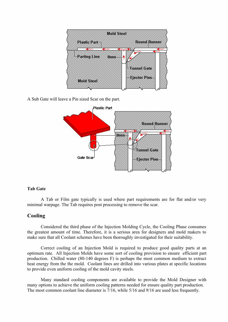
A Sub Gate will leave a Pin sized Scar on the part.
Tab Gate
A Tab or Film gate typically is used where part requirements are for flat and/or very minimal warpage. The Tab requires post processing to remove the scar.
Cooling
Considered the third phase of the Injection Molding Cycle, the Cooling Phase consumes the greatest amount of time. Therefore, it is a serious area for designers and mold makers to make sure that all Coolant schemes have been thoroughly investigated for their suitability.
Correct cooling of an Injection Mold is required to produce good quality parts at an optimum rate. All Injection Molds have some sort of cooling provision to ensure efficient part production. Chilled water (80-140 degrees F) is perhaps the most common medium to extract heat energy from the the mold. Coolant lines are drilled into various plates at specific locations to provide even uniform cooling of the mold cavity steels.
Many standard cooling components are available to provide the Mold Designer with many options to achieve the uniform cooling patterns needed for ensure quality part production. The most common coolant line diameter is 7/16, while 5/16 and 9/16 are used less frequently.
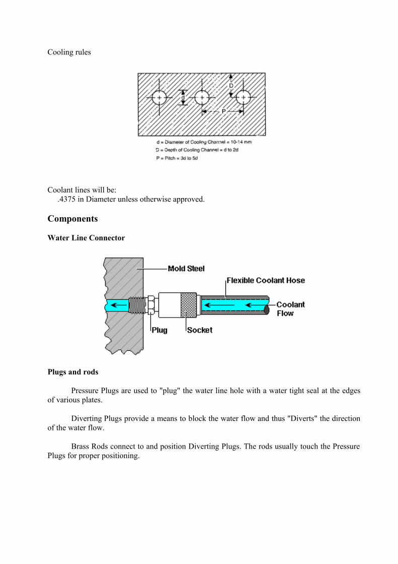
Cooling rules
Coolant lines will be: .4375 in Diameter unless otherwise approved.
Components
Water Line Connector
Plugs and rods
Pressure Plugs are used to "plug" the water line hole with a water tight seal at the edges of various plates.
Diverting Plugs provide a means to block the water flow and thus "Diverts" the direction of the water flow.
Brass Rods connect to and position Diverting Plugs. The rods usually touch the Pressure Plugs for proper positioning.
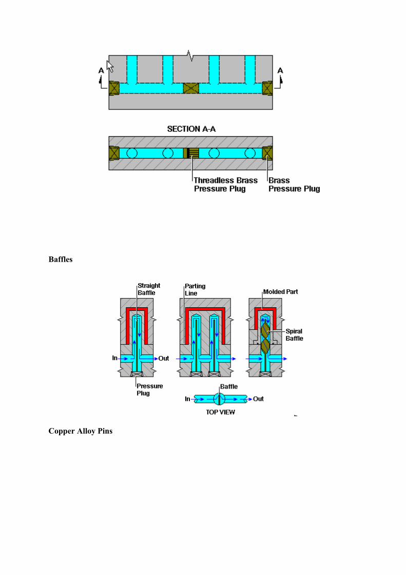
Baffles
Copper Alloy Pins
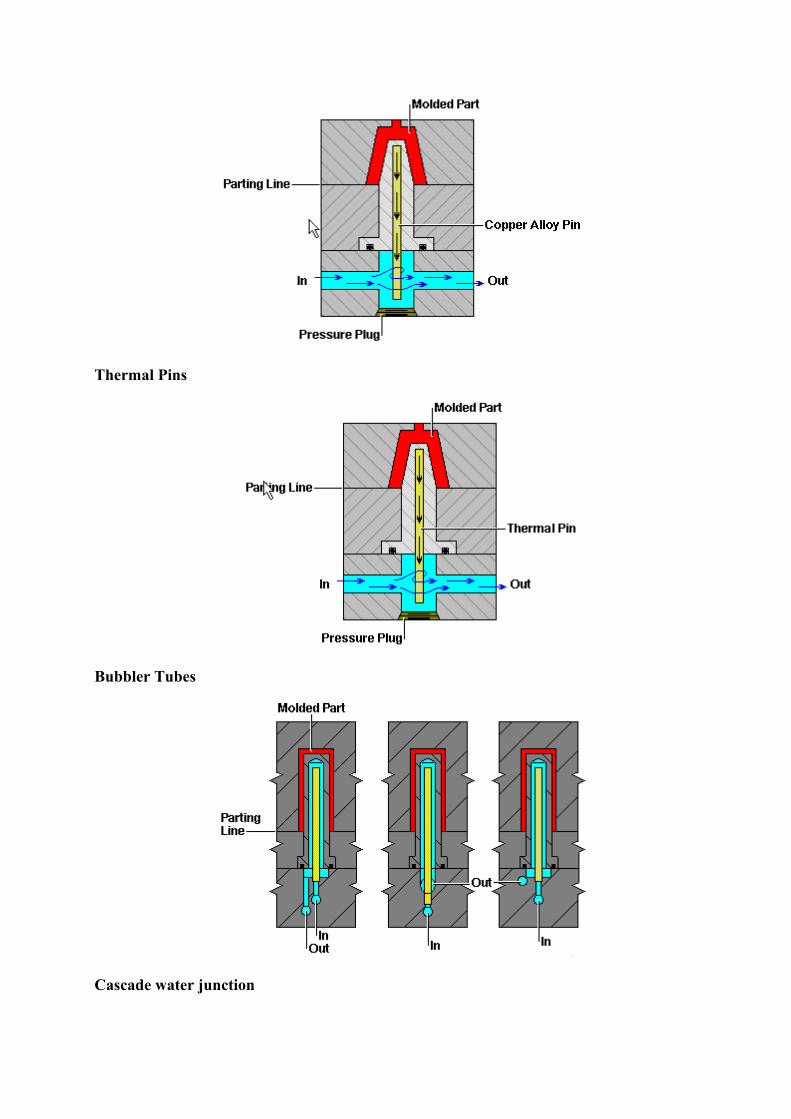
Thermal Pins
Bubbler Tubes
Cascade water junction
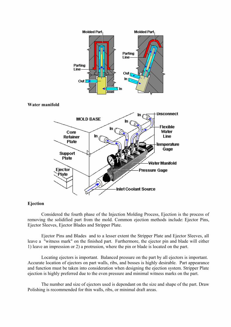
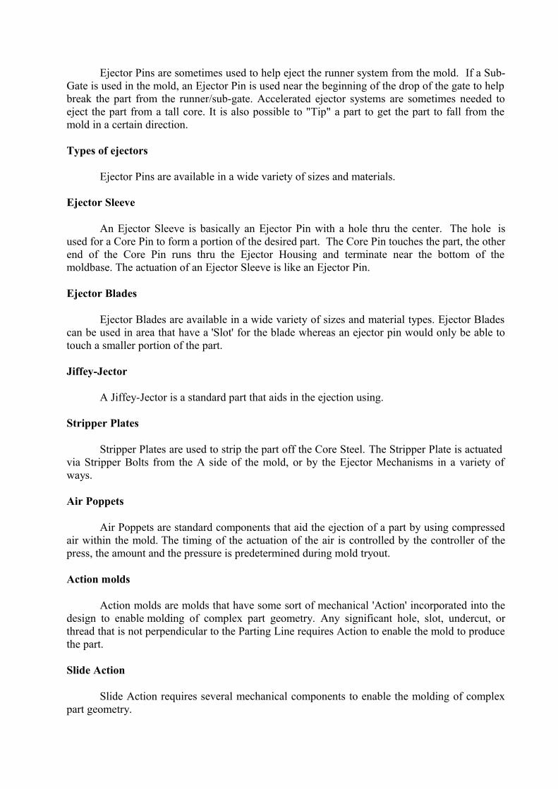
Water manifold
Ejection
Considered the fourth phase of the Injection Molding Process, Ejection is the process of removing the solidified part from the mold. Common ejection methods include: Ejector Pins, Ejector Sleeves, Ejector Blades and Stripper Plate.
Ejector Pins and Blades and to a lesser extent the Stripper Plate and Ejector Sleeves, all leave a "witness mark" on the finished part. Furthermore, the ejector pin and blade will either 1) leave an impression or 2) a protrusion, where the pin or blade is located on the part.
Locating ejectors is important. Balanced pressure on the part by all ejectors is important. Accurate location of ejectors on part walls, ribs, and bosses is highly desirable. Part appearance and function must be taken into consideration when designing the ejection system. Stripper Plate ejection is highly preferred due to the even pressure and minimal witness marks on the part.
The number and size of ejectors used is dependant on the size and shape of the part. Draw Polishing is recommended for thin walls, ribs, or minimal draft areas.
Ejector Pins are sometimes used to help eject the runner system from the mold. If a Sub-Gate is used in the mold, an Ejector Pin is used near the beginning of the drop of the gate to help break the part from the runner/sub-gate. Accelerated ejector systems are sometimes needed to eject the part from a tall core. It is also possible to "Tip" a part to get the part to fall from the mold in a certain direction.
Types of ejectors
Ejector Pins are available in a wide variety of sizes and materials.
Ejector Sleeve
An Ejector Sleeve is basically an Ejector Pin with a hole thru the center. The hole is used for a Core Pin to form a portion of the desired part. The Core Pin touches the part, the other end of the Core Pin runs thru the Ejector Housing and terminate near the bottom of the moldbase. The actuation of an Ejector Sleeve is like an Ejector Pin.
Ejector Blades
Ejector Blades are available in a wide variety of sizes and material types. Ejector Blades can be used in area that have a 'Slot' for the blade whereas an ejector pin would only be able to touch a smaller portion of the part.
Jiffey-Jector
A Jiffey-Jector is a standard part that aids in the ejection using.
Stripper Plates
Stripper Plates are used to strip the part off the Core Steel. The Stripper Plate is actuated via Stripper Bolts from the A side of the mold, or by the Ejector Mechanisms in a variety of ways.
Air Poppets
Air Poppets are standard components that aid the ejection of a part by using compressed air within the mold. The timing of the actuation of the air is controlled by the controller of the press, the amount and the pressure is predetermined during mold tryout.
Action molds
Action molds are molds that have some sort of mechanical 'Action' incorporated into the design to enable molding of complex part geometry. Any significant hole, slot, undercut, or thread that is not perpendicular to the Parting Line requires Action to enable the mold to produce the part.
Slide Action
Slide Action requires several mechanical components to enable the molding of complex part geometry.
Slide Action molds typically contain the following components:
Angle/Cam/Horn PinSlideL-GibsWear PlateSlide RetainerSlide Lock
Note: The L-Gib should NOT move with the slide.
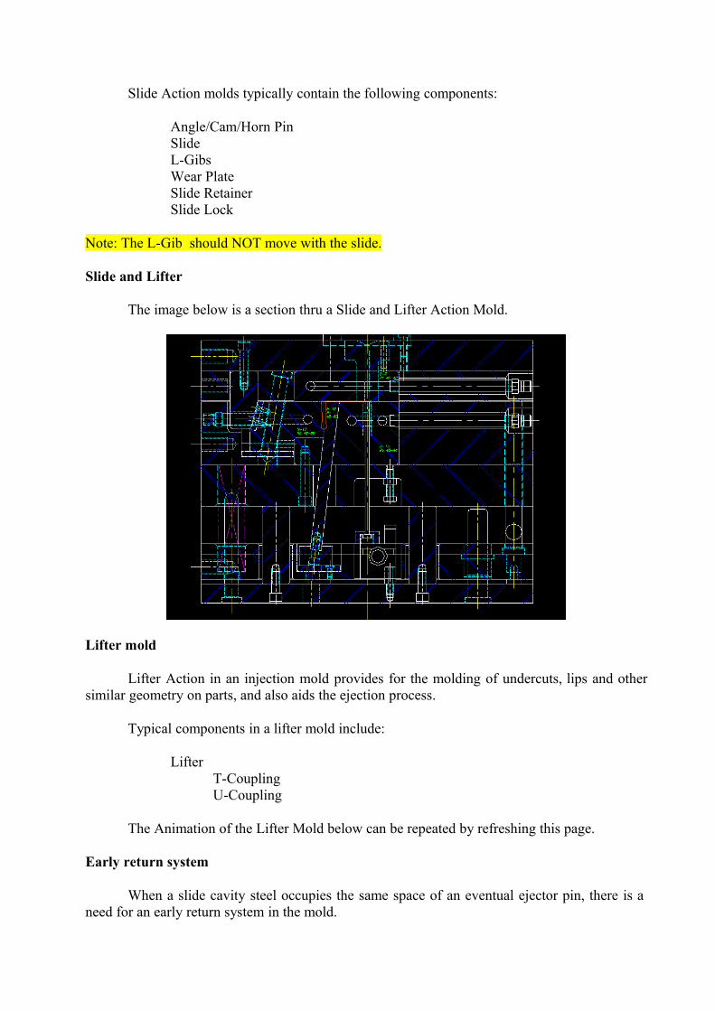
Slide and Lifter
The image below is a section thru a Slide and Lifter Action Mold.
Lifter mold
Lifter Action in an injection mold provides for the molding of undercuts, lips and other similar geometry on parts, and also aids the ejection process.
Typical components in a lifter mold include:
Lifter T-Coupling U-Coupling
The Animation of the Lifter Mold below can be repeated by refreshing this page.
Early return system
When a slide cavity steel occupies the same space of an eventual ejector pin, there is a need for an early return system in the mold.
If an early return system is not designed into a mold with the circumstances above, the slide will attempt to return to the closed position, before the ejector pin is returned, and will cause a collision.
Hydraulic Action
Hydraulic Action in an Injection Mold, usually means that a hydraulic cylinder has been incorporated into the design to enable a component (core pin, cavity steel, etc) to be moved at some phase during the injection molding cycle.
Typical components for Hydraulic Action are:
The Hydraulic Cylinder Mounting Bracket, and relater connectors
The timing control of the actuation of the Hydraulic cylinder is typically done via Electrical/Mechanical switches attached to the mold base, or, more commonly directly attached to the controller of the press.
Collapsible Core
Collapsible Core molds provide a method to produce under cut 'Lips or Threads" in an injection molded part.
Standard collapsible cores can be purchased with altering of the portion that forms a portion of the part. If a standard collapsible core will not work in a particular design it is usually possible to design one to meet the design requirement.
Gearing
Gearing with an injection mold to produce full threads is common. There are many considerations (Part, Press, Size of Mold base, Number of cavities, etc…) that have to be considered to produce the pasts to specification.Hot Runner Mold
A Hot Runner Mold is similar to a hot glue gun. Material heated to a molten state, then it is dispensed at the tip to the desired area. Hot Runner Molds have many unique advantages over "Cold Runner" molds.
While Hot Runner Molds are typically more expensive than a "Cold Runner" molds, the cost of the mold can be offset in other ways. Thermoplastic Hot Runner Molds can reduce costs by the following:
No scraping of the runner. As the term implies, the runner in a Hot Runner mold stays in a molten state at all times.
Reducing the cycle time. In a Cold Runner mold the runner typically has the largest cross sectional area, therefore, the runner takes longer to solidify. Eliminating the runner reduces the overall cycle time. Furthermore, injection time is reduced due to the shot size being reduced by the elimination of the runner.
Hot Runner Molds have the ability to improve both part and mold design with flexibility of gating locations, which provides options for cavity orientation. Pressure drops are greatly reduced due to the balanced melt flow as the temperature is consistent from the nozzle to the gate.
View of cavity
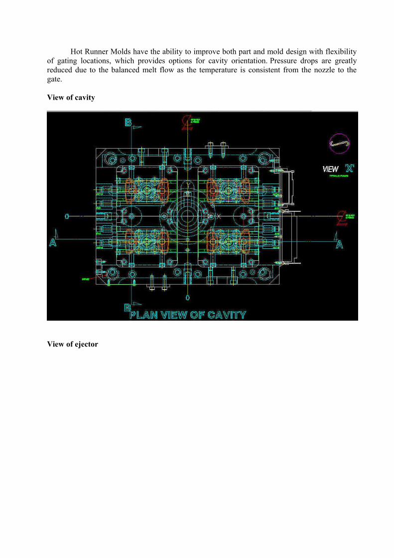
View of ejector
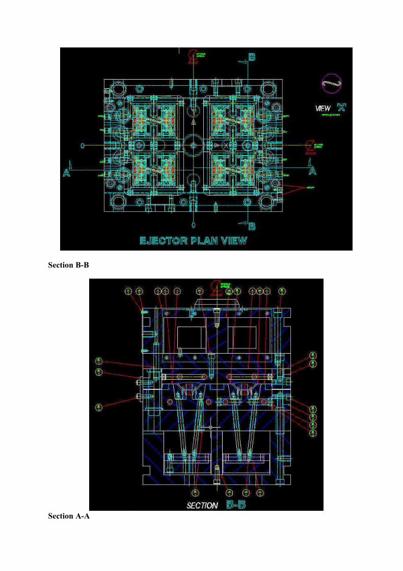
Section B-B
Section A-A
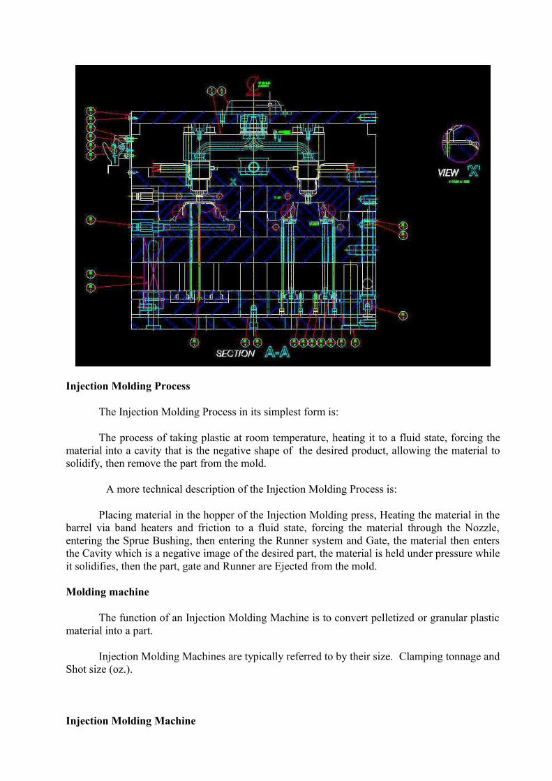
Injection Molding Process
The Injection Molding Process in its simplest form is:
The process of taking plastic at room temperature, heating it to a fluid state, forcing the material into a cavity that is the negative shape of the desired product, allowing the material to solidify, then remove the part from the mold.
A more technical description of the Injection Molding Process is:
Placing material in the hopper of the Injection Molding press, Heating the material in the barrel via band heaters and friction to a fluid state, forcing the material through the Nozzle, entering the Sprue Bushing, then entering the Runner system and Gate, the material then enters the Cavity which is a negative image of the desired part, the material is held under pressure while it solidifies, then the part, gate and Runner are Ejected from the mold.
Molding machine
The function of an Injection Molding Machine is to convert pelletized or granular plastic material into a part.
Injection Molding Machines are typically referred to by their size. Clamping tonnage and Shot size (oz.).
Injection Molding Machine
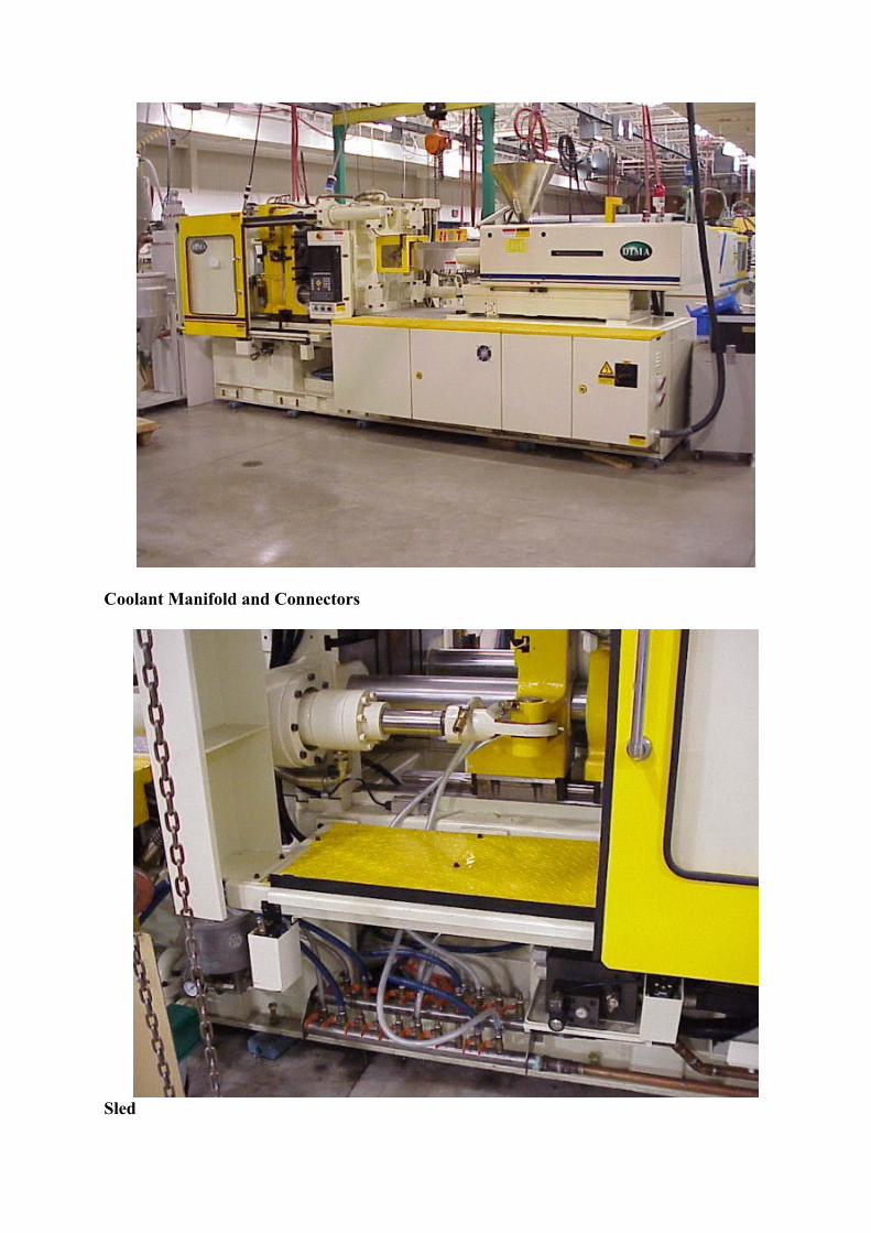
Coolant Manifold and Connectors
Sled
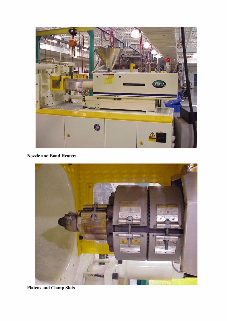
Nozzle and Band Heaters
Platens and Clamp Slots
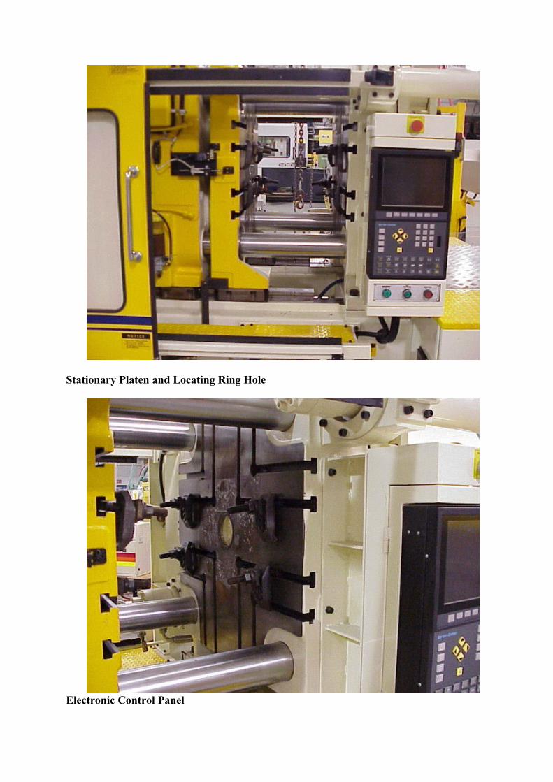
Stationary Platen and Locating Ring Hole
Electronic Control Panel
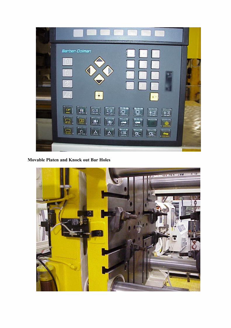
Movable Platen and Knock out Bar Holes
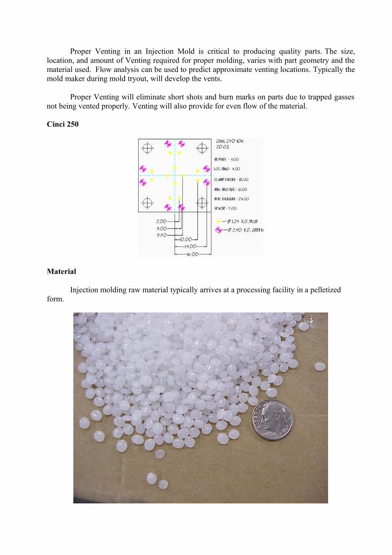
Proper Venting in an Injection Mold is critical to producing quality parts. The size, location, and amount of Venting required for proper molding, varies with part geometry and the material used. Flow analysis can be used to predict approximate venting locations. Typically the mold maker during mold tryout, will develop the vents.
Proper Venting will eliminate short shots and burn marks on parts due to trapped gasses not being vented properly. Venting will also provide for even flow of the material.
Cinci 250
Material
Injection molding raw material typically arrives at a processing facility in a pelletized form.
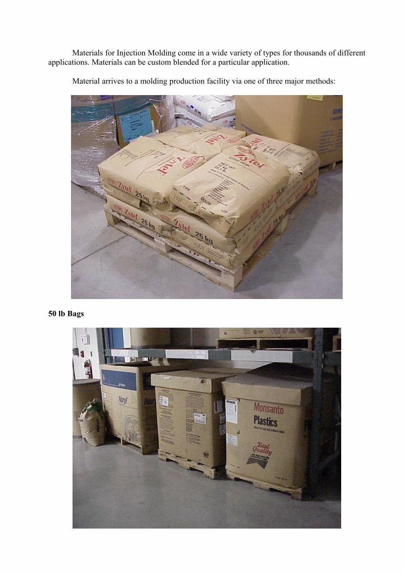
Materials for Injection Molding come in a wide variety of types for thousands of different applications. Materials can be custom blended for a particular application.
Material arrives to a molding production facility via one of three major methods:
50 lb Bags
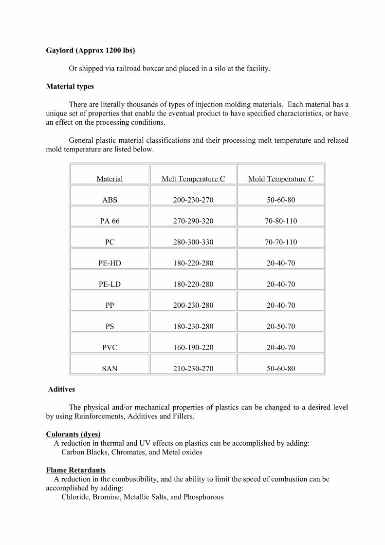
Gaylord (Approx 1200 lbs)
Or shipped via railroad boxcar and placed in a silo at the facility.
Material types
There are literally thousands of types of injection molding materials. Each material has a unique set of properties that enable the eventual product to have specified characteristics, or have an effect on the processing conditions.
General plastic material classifications and their processing melt temperature and related mold temperature are listed below.
Material Melt Temperature C Mold Temperature C
ABS 200-230-270 50-60-80
PA 66 270-290-320 70-80-110
PC 280-300-330 70-70-110
PE-HD 180-220-280 20-40-70
PE-LD 180-220-280 20-40-70
PP 200-230-280 20-40-70
PS 180-230-280 20-50-70
PVC 160-190-220 20-40-70
SAN 210-230-270 50-60-80
Aditives
The physical and/or mechanical properties of plastics can be changed to a desired level by using Reinforcements, Additives and Fillers.
Colorants (dyes) A reduction in thermal and UV effects on plastics can be accomplished by adding: Carbon Blacks, Chromates, and Metal oxides
Flame Retardants A reduction in the combustibility, and the ability to limit the speed of combustion can be accomplished by adding: Chloride, Bromine, Metallic Salts, and Phosphorous
Conductive Fillers Electrical and Thermal conductivity can be enhanced by adding: Aluminum Powders, Graphite, Carbon Fibers
Reinforcement Fibers An increase in Tensile Strength, Flexural Modulus, and Heat-Deflection Temperature, as well as reducing Shrinkage and Warpage can be attained by adding: Kevlar, Glass, Baron, Carbon, and Fibrous Minerals
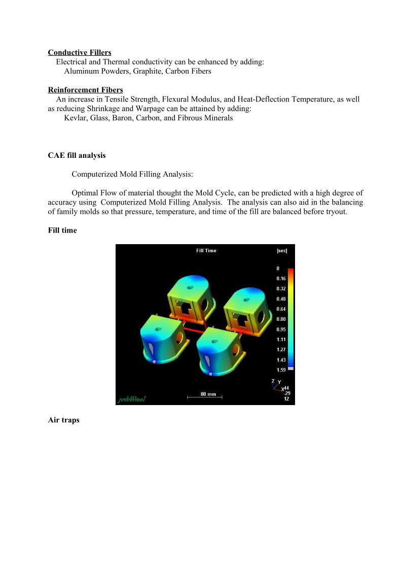
CAE fill analysis
Computerized Mold Filling Analysis:
Optimal Flow of material thought the Mold Cycle, can be predicted with a high degree of accuracy using Computerized Mold Filling Analysis. The analysis can also aid in the balancing of family molds so that pressure, temperature, and time of the fill are balanced before tryout.
Fill time
Air traps
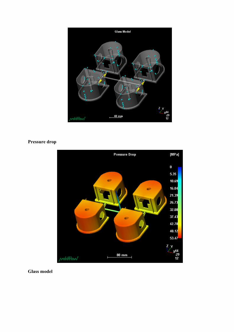
Pressure drop
Glass model
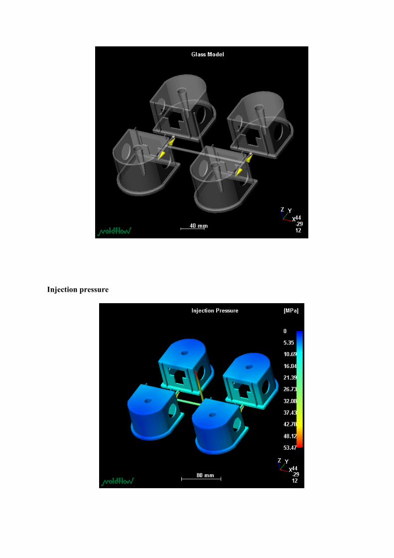
Injection pressure
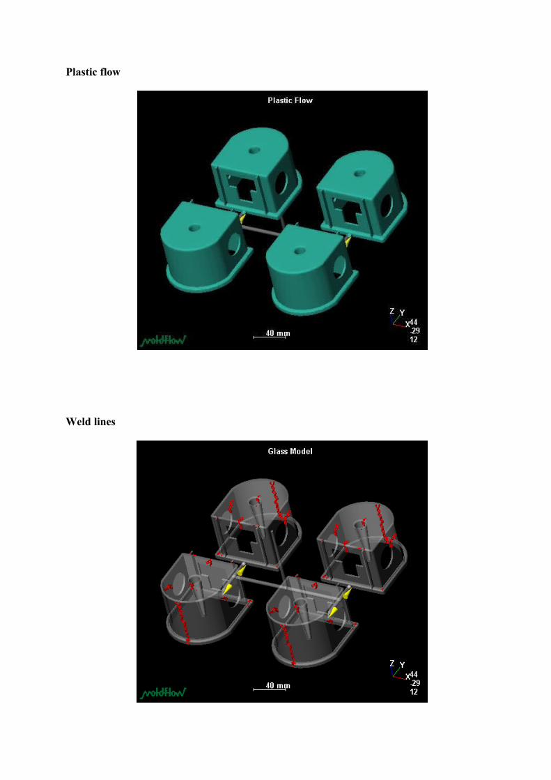
Plastic flow
Weld lines
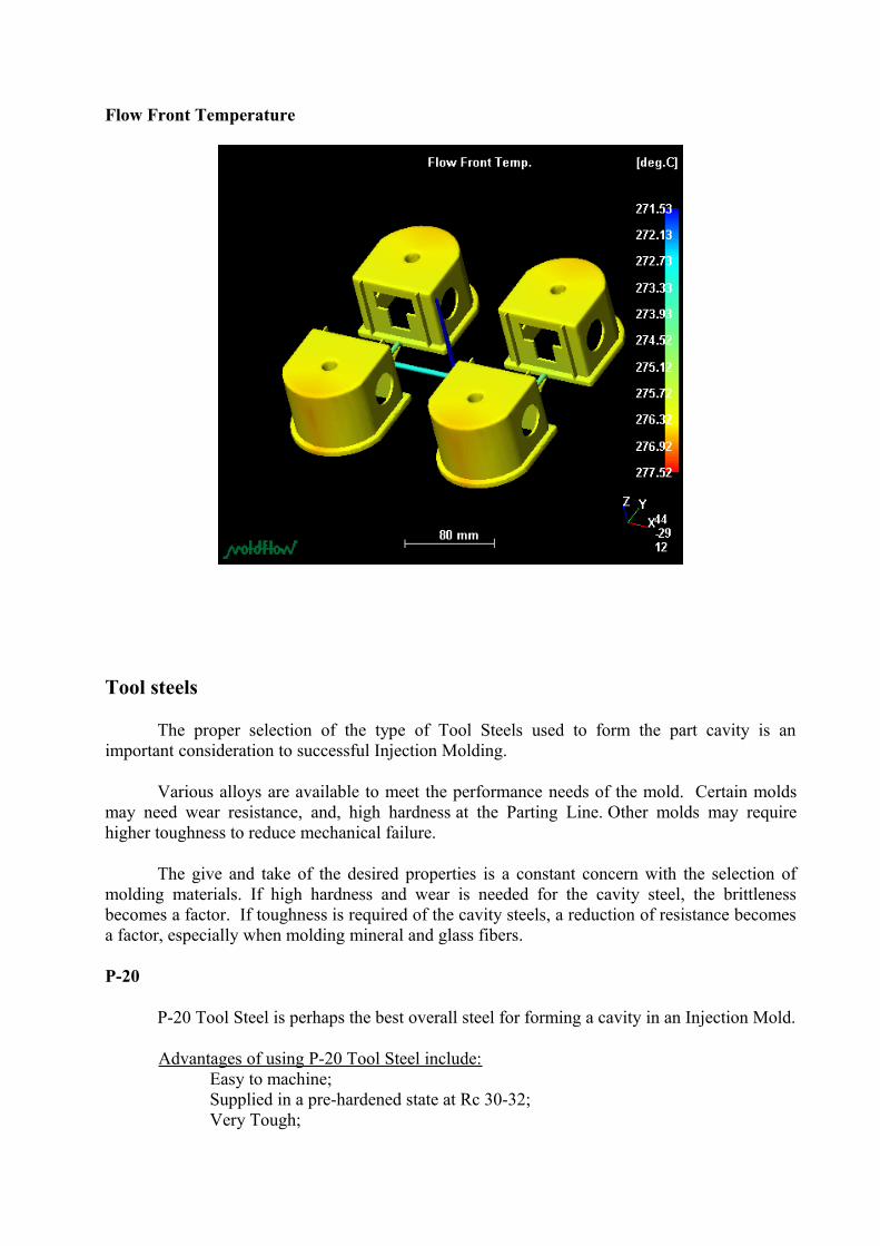
Flow Front Temperature
Tool steels
The proper selection of the type of Tool Steels used to form the part cavity is an important consideration to successful Injection Molding.
Various alloys are available to meet the performance needs of the mold. Certain molds may need wear resistance, and, high hardness at the Parting Line. Other molds may require higher toughness to reduce mechanical failure.
The give and take of the desired properties is a constant concern with the selection of molding materials. If high hardness and wear is needed for the cavity steel, the brittleness becomes a factor. If toughness is required of the cavity steels, a reduction of resistance becomes a factor, especially when molding mineral and glass fibers.
P-20
P-20 Tool Steel is perhaps the best overall steel for forming a cavity in an Injection Mold.
Advantages of using P-20 Tool Steel include: Easy to machine; Supplied in a pre-hardened state at Rc 30-32; Very Tough;
Large sizes are minimal risks during heat treat Can be used for abrasive materials, for short runs.
Disadvantages of P-20 include:No moving of mating steels of P-20 as galling will occur, H-13 is a suitable alternative steel for this application.
H-13
H-13 Tool Steel provides significant toughness in an injection mold. At a Rc of 50-52 mechanical fatigue resistance is reduced, compared to other higher hardness steels.
Advantages of H-13 include: Toughness
Disadvantages of H-13 include: Low hardness (relative to S-7)
S-7
S-7 is similar to H-13, as it has very high toughness, and resistance to mechanical fatigue.
Advantages of S-7 include: Toughness Hardness Mechanical Fatigue resistance
Disadvantages of S-7 include: Lower abrasive resistance (relative to H-13).
Other tool steels
Miscellaneous Tool Steels
A-2, D-2 and M-2 Tool Steels are typically used for Gate Inserts when molding materials filled with glass or mineral additives.
Corrosion
Corrosion may occur during: The storage of the injection mold The operation of a mold in a high humidity environment The molding of material that emits gasses that are prone to aiding the corrosion process.
Preventing Corrosion is important to an injection mold that is required to produce parts over a long period of time.
Preventative measures include: Spraying the mold with a protective coating
Nickel plating Making the mold cavities from Stainless Steel
Alternative Processes
Co-injection
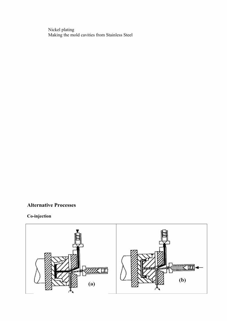
Fusible Core
Gas-Assisted
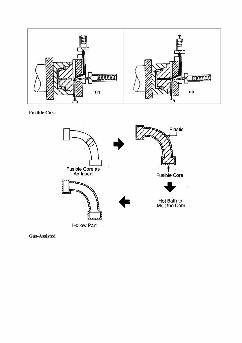
Low-Pressure
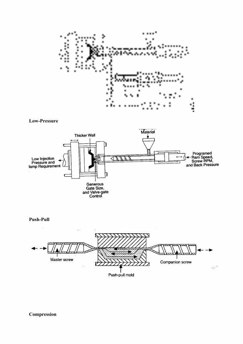
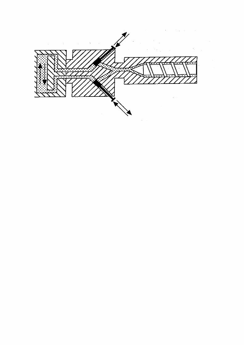
Push-Pull
Compression
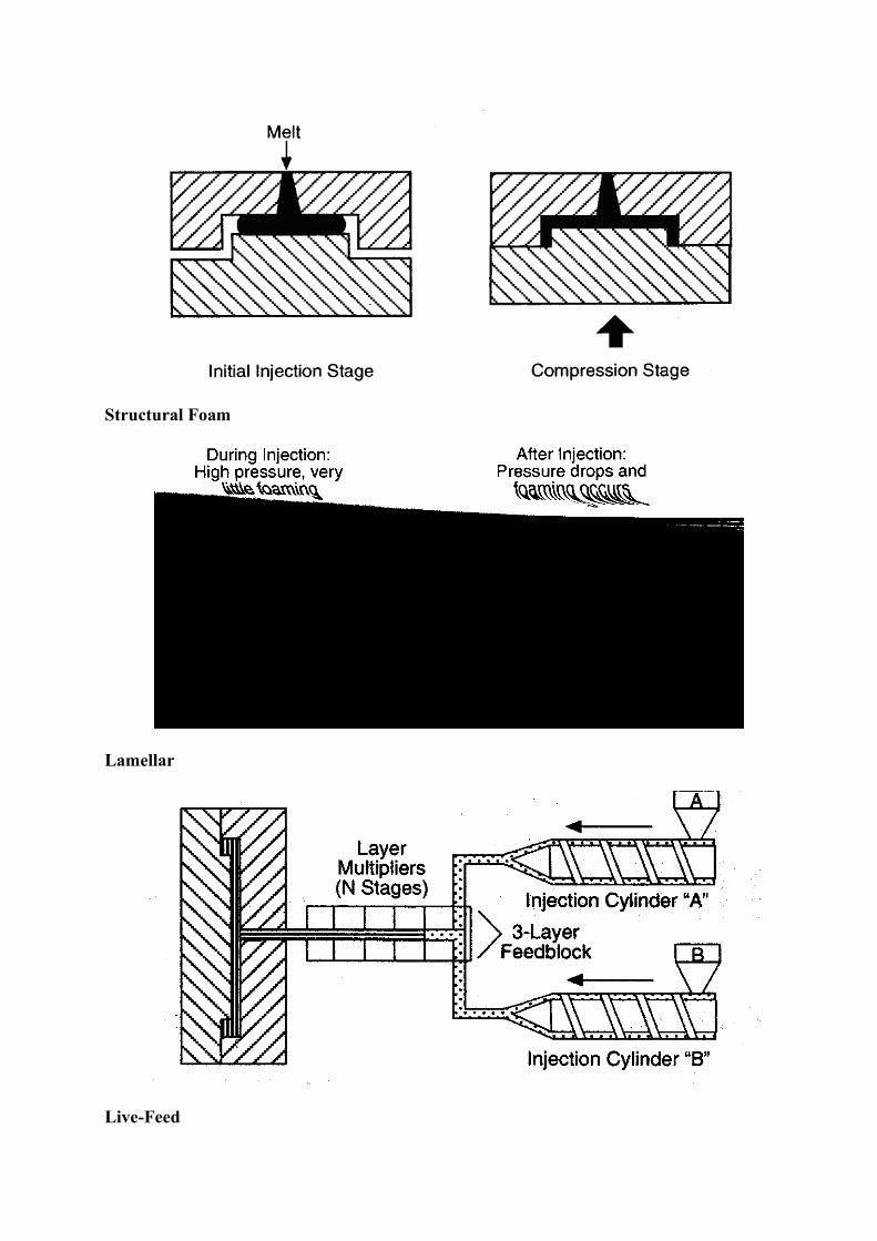
Structural Foam
Lamellar
Live-Feed
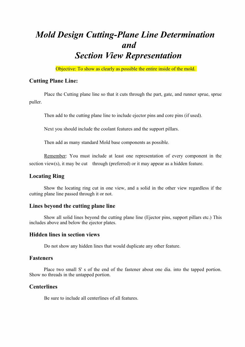
Mold Design Cutting-Plane Line Determination and
Section View Representation Objective: To show as clearly as possible the entire inside of the mold.
Cutting Plane Line:
Place the Cutting plane line so that it cuts through the part, gate, and runner sprue, sprue
puller.
Then add to the cutting plane line to include ejector pins and core pins (if used).
Next you should include the coolant features and the support pillars.
Then add as many standard Mold base components as possible.
Remember: You must include at least one representation of every component in the
section view(s), it may be cut through (preferred) or it may appear as a hidden feature.
Locating Ring
Show the locating ring cut in one view, and a solid in the other view regardless if the cutting plane line passed through it or not.
Lines beyond the cutting plane line
Show all solid lines beyond the cutting plane line (Ejector pins, support pillars etc.) This includes above and below the ejector plates.
Hidden lines in section views
Do not show any hidden lines that would duplicate any other feature.
Fasteners
Place two small S' s of the end of the fastener about one dia. into the tapped portion. Show no threads in the untapped portion.
Centerlines
Be sure to include all centerlines of all features.
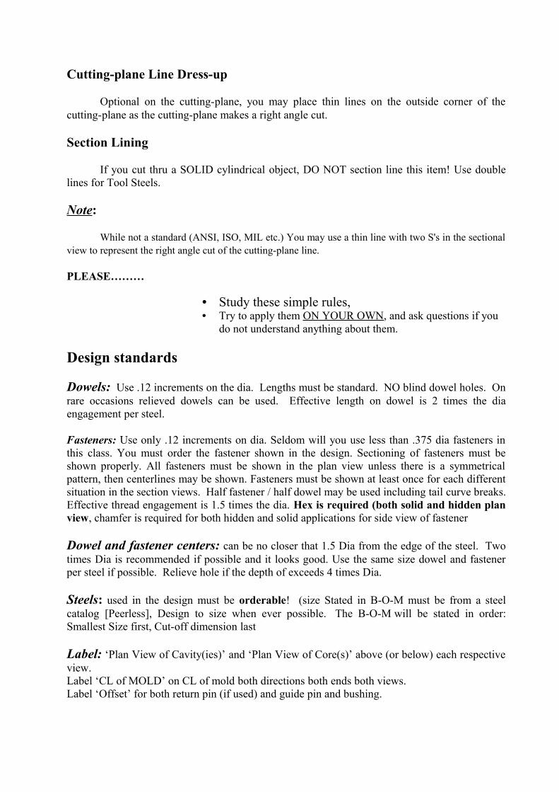
Cutting-plane Line Dress-up
Optional on the cutting-plane, you may place thin lines on the outside corner of the cutting-plane as the cutting-plane makes a right angle cut.
Section Lining
If you cut thru a SOLID cylindrical object, DO NOT section line this item! Use double lines for Tool Steels.
Note:
While not a standard (ANSI, ISO, MIL etc.) You may use a thin line with two S's in the sectional view to represent the right angle cut of the cutting-plane line.
PLEASE………
• Study these simple rules, • Try to apply them ON YOUR OWN, and ask questions if you
do not understand anything about them.
Design standards
Dowels: Use .12 increments on the dia. Lengths must be standard. NO blind dowel holes. On rare occasions relieved dowels can be used. Effective length on dowel is 2 times the dia engagement per steel.
Fasteners: Use only .12 increments on dia. Seldom will you use less than .375 dia fasteners in this class. You must order the fastener shown in the design. Sectioning of fasteners must be shown properly. All fasteners must be shown in the plan view unless there is a symmetrical pattern, then centerlines may be shown. Fasteners must be shown at least once for each different situation in the section views. Half fastener / half dowel may be used including tail curve breaks. Effective thread engagement is 1.5 times the dia. Hex is required (both solid and hidden plan view, chamfer is required for both hidden and solid applications for side view of fastener
Dowel and fastener centers: can be no closer that 1.5 Dia from the edge of the steel. Two times Dia is recommended if possible and it looks good. Use the same size dowel and fastener per steel if possible. Relieve hole if the depth of exceeds 4 times Dia.
Steels: used in the design must be orderable! (size Stated in B-O-M must be from a steel catalog [Peerless], Design to size when ever possible. The B-O-M will be stated in order: Smallest Size first, Cut-off dimension last
Label: ‘Plan View of Cavity(ies)’ and ‘Plan View of Core(s)’ above (or below) each respective view. Label ‘CL of MOLD’ on CL of mold both directions both ends both views.Label ‘Offset’ for both return pin (if used) and guide pin and bushing.
Stamp: Place a general note:
Stamp: Ferris State University
CAD Drafting Tool Design
Tool # MMDDYY-MX (Month DateYear-start with M01)
Part Number is the same as Tool Number except replace M with a P
Cutting Plane Line: will be Phantom (see handout on determination).Thickness: .050 Thick for plotter, .013 Thick for printer. Use proper setup in CAD for both plotting and printing.
Section ID’s: (AA, BB etc.) are placed in back of the arrows and are .38 in height.
Section View ID Text: Height is also .38
Section Arrows: are to be created with a curve on the back end and with a colored gradual shadeing fillin (ask for example). Section arrows must be in a ratio of approx 4 to 1 (length to width).
Cutting Plane Line must contain offsets: These are “outside corners” for dress-up and clarity (ask for example).
Underline: all lettering except lettering inside the StockList.
Inserts: Symmetrical inserts must be fool proofed.
Radius machined pockets for proper standard size cutter
Chamfer Steels to fit machined pocketss.
Balloons: Will be placed in a logical order. Balloon Dia is .43 with .18 number height..
Leaders: will have a gradual curve, and point into the detail at the edge of the detail (not on). A period on the detail may be used with permission.
Tool Steel Cross Hatching: is two lines double gap. DO not hatch too close! Use a wide spaced hatch pattern for support pillars, code pattern for return pins is upper right lower left, ejector pins upper left lower right.
Red Shading for Part: Runner, Gate, and Sprue, is required in the Section view only. Edges of steels need to be black.
Text Size: will be .18 in height. Section ID letters will be .38 in height.
Steel size selection and specification: Mold Cavity tool steels will be H-13 and/or P-20. Sizes must be orderable if possible. Small-medium-largest, will be the order sizes of specification in the stock list. Example: 1.000 x 2.000 3.12. Furthermore, add a .12 inch more than your designed size for stock cutoff to the largest size. The sizes will have 3-place X 3-place X 2-place decimals
in the stock list (see example). All carbon steels will be specified as C-1018, C-11L17, C-1045, or C-1060, DO NOT use CRS, CFS.
Position of detail: If details are shown out of position it must be noted on the leader line, and or on the detail itself.
Center line: Place centerlines on ALL appropriate features, this is required!.
Text:
All Fonts Except Section ID and Plan View Labels, on layout shall be:
Romans with an Oblique setting of 15.
Notes Text Height is .18.
Bill of Materials and Title block (ddedit but, be sure to change the font).
Sectioning (See Sectioning/Hatchine).
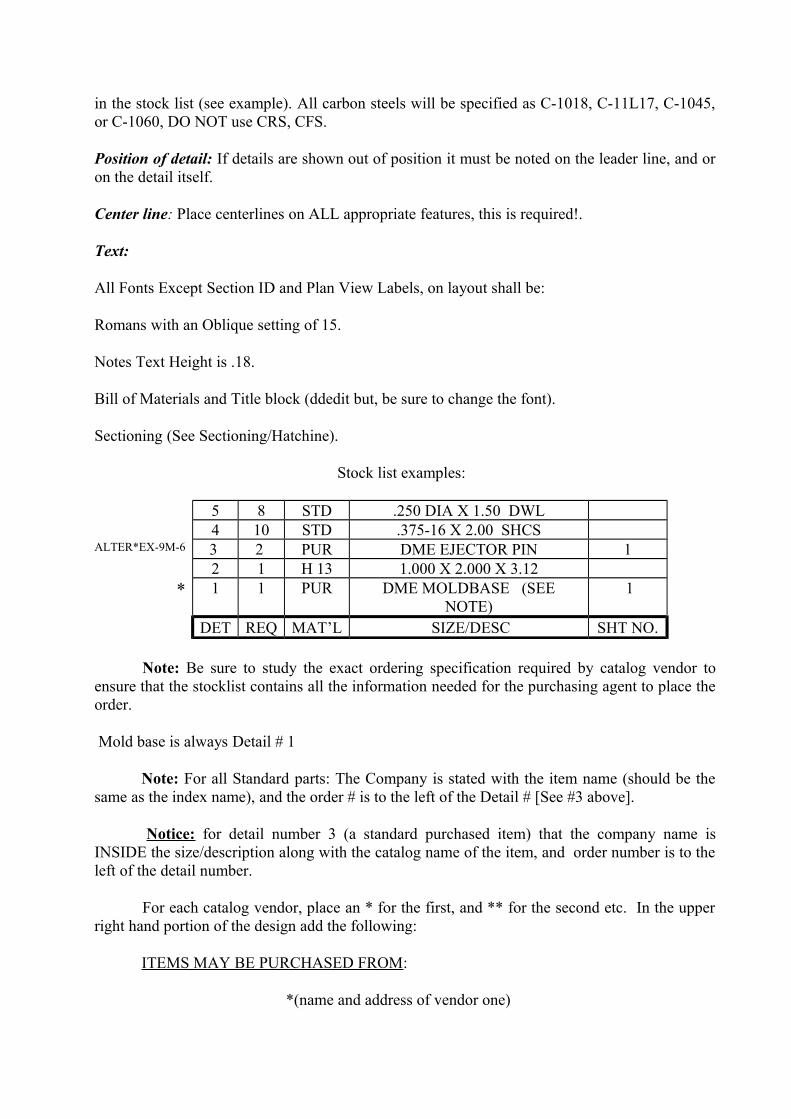
Stock list examples:
5 8 STD .250 DIA X 1.50 DWL 4 10 STD .375-16 X 2.00 SHCS
ALTER*EX-9M-6 3 2 PUR DME EJECTOR PIN 1 2 1 H 13 1.000 X 2.000 X 3.12
* 1 1 PUR DME MOLDBASE (SEE NOTE)
1
DET REQ MAT’L SIZE/DESC SHT NO.
Note: Be sure to study the exact ordering specification required by catalog vendor to ensure that the stocklist contains all the information needed for the purchasing agent to place the order.
Mold base is always Detail # 1
Note: For all Standard parts: The Company is stated with the item name (should be the same as the index name), and the order # is to the left of the Detail # [See #3 above].
Notice: for detail number 3 (a standard purchased item) that the company name is INSIDE the size/description along with the catalog name of the item, and order number is to the left of the detail number.
For each catalog vendor, place an * for the first, and ** for the second etc. In the upper right hand portion of the design add the following:
ITEMS MAY BE PURCHASED FROM:
*(name and address of vendor one)
** (name and address of vendor two)
Note:
Standard in our shop will be:
ALL fasteners (SHCS, and Stripper Bolts) washers, and nuts.
When ordering Steels, place the material type is the Material Column
Use NO Fractions in the B-O-M
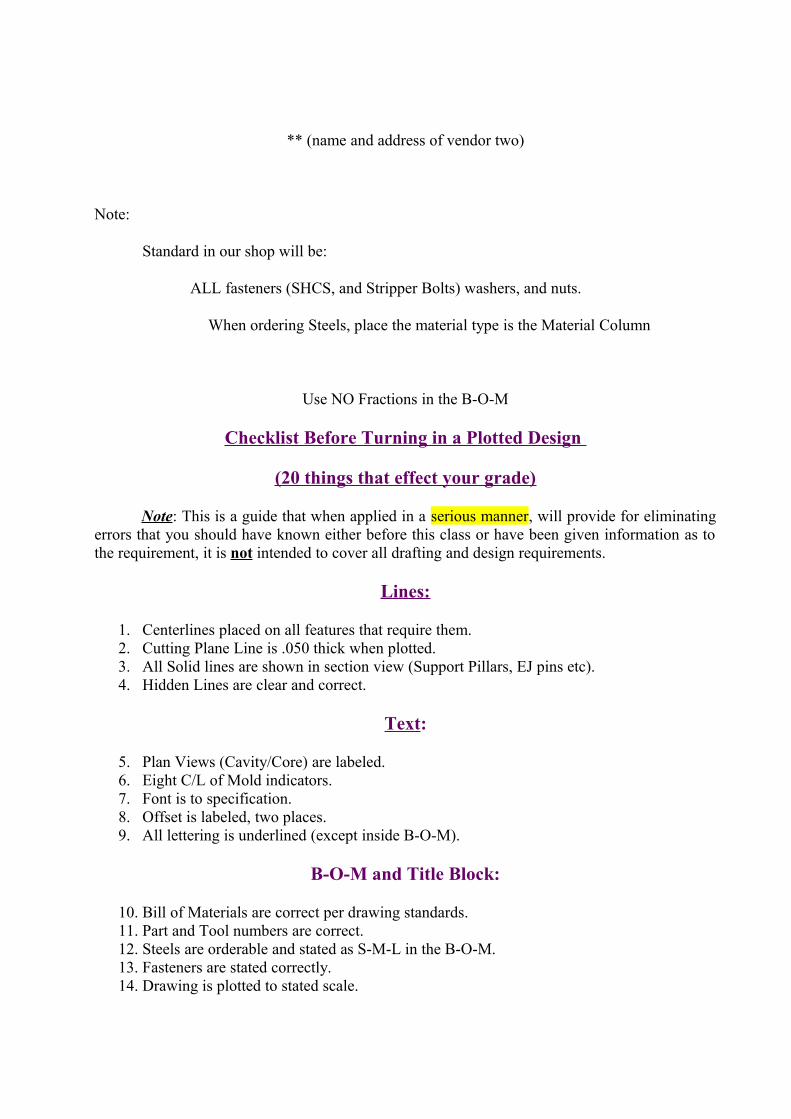
Checklist Before Turning in a Plotted Design
(20 things that effect your grade)
Note: This is a guide that when applied in a serious manner, will provide for eliminating errors that you should have known either before this class or have been given information as to the requirement, it is not intended to cover all drafting and design requirements.
Lines:
1. Centerlines placed on all features that require them. 2. Cutting Plane Line is .050 thick when plotted. 3. All Solid lines are shown in section view (Support Pillars, EJ pins etc). 4. Hidden Lines are clear and correct.
Text:
5. Plan Views (Cavity/Core) are labeled. 6. Eight C/L of Mold indicators. 7. Font is to specification. 8. Offset is labeled, two places. 9. All lettering is underlined (except inside B-O-M).
B-O-M and Title Block:
10. Bill of Materials are correct per drawing standards. 11. Part and Tool numbers are correct. 12. Steels are orderable and stated as S-M-L in the B-O-M. 13. Fasteners are stated correctly. 14. Drawing is plotted to stated scale.
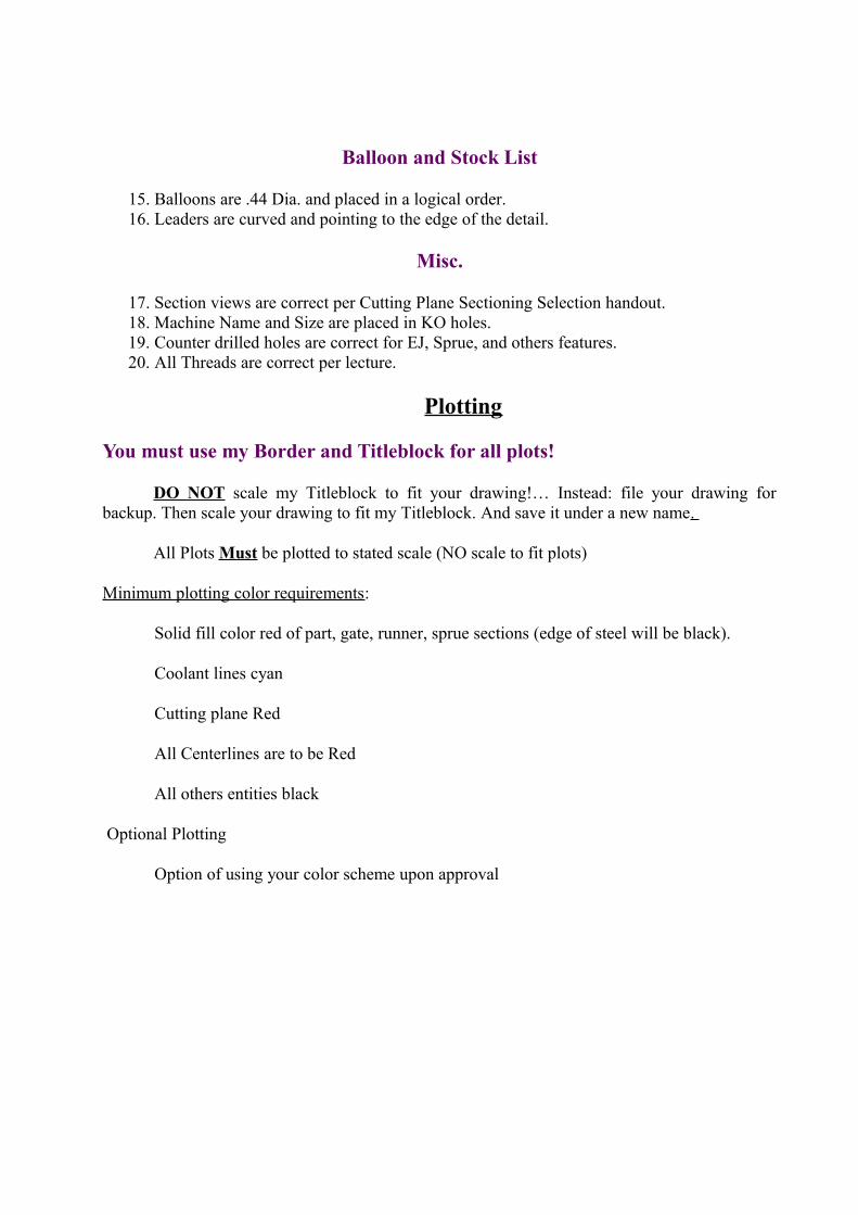
Balloon and Stock List
15. Balloons are .44 Dia. and placed in a logical order. 16. Leaders are curved and pointing to the edge of the detail.
Misc.
17. Section views are correct per Cutting Plane Sectioning Selection handout. 18. Machine Name and Size are placed in KO holes. 19. Counter drilled holes are correct for EJ, Sprue, and others features.20. All Threads are correct per lecture.
Plotting
You must use my Border and Titleblock for all plots!
DO NOT scale my Titleblock to fit your drawing!… Instead: file your drawing for backup. Then scale your drawing to fit my Titleblock. And save it under a new name.
All Plots Must be plotted to stated scale (NO scale to fit plots)
Minimum plotting color requirements:
Solid fill color red of part, gate, runner, sprue sections (edge of steel will be black).
Coolant lines cyan
Cutting plane Red
All Centerlines are to be Red
All others entities black
Optional Plotting
Option of using your color scheme upon approval

Note: NO plotting of any yellow lines at anytime !
Design review:
Mark Hill
DESIGN DEPARTMENT CHECK LIST
Part Name:___________ Tool #_______________Metric/English
Part File Name:___________ Tool File Name:____________Metric/English
A. PART DATA / LINE UP INFO Chk’d
01. Has the job folder been Created?02. Have part edits been reviewed?03. Kick off notes reviewed?04. Has the customer specs been reviewed?05. Has die draw been supplied by the customer or determined by the designer?06. Has draft analysis been run with minimum draft established?07. Is draft analysis copy included with folder and checklist?08. Has the part been completely reviewed for molding?09. Is part data complete? ISM & OSM?10. Are part changes required? If so, are sketches attached?11. Do all ribs have adequate draft?12. Are ribs too thick at the base? (40% - 50% Max.)?13. Do bosses have adequate draft? (Min. 0.5° on O.D. & I.D.) ?14 What is the shrink factor?15. Are parts identical? Mirrored or rotated?
B. RUNOFF Chk’d
01. Has the parting line been completely defined?02. Is relief shown?03. Are vents shown? With a blow up detail of vent on the sheet the vents are on?04. Is runoff complete?05. Do mold locks have counter locks?06. Are all locks on 10°?07. Is shutoff shown on correct half of mold?08. Can the return pins fit into shutoff?09. Is there shutoff around drops and runners (Min. 1.00)?10. Is there clearance in the core for hot drop expansion? (Wafer if possible)?
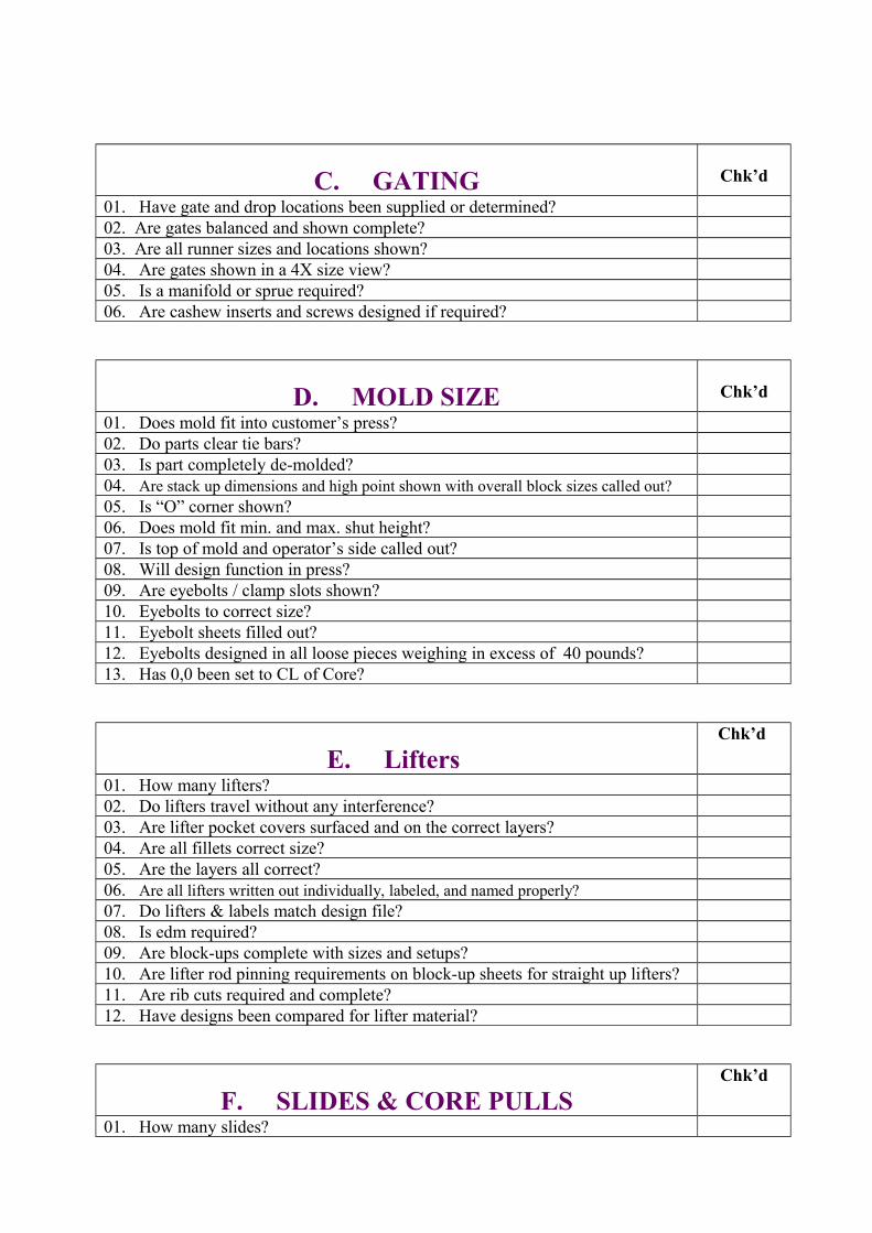
C. GATING Chk’d
01. Have gate and drop locations been supplied or determined?02. Are gates balanced and shown complete?03. Are all runner sizes and locations shown?04. Are gates shown in a 4X size view?05. Is a manifold or sprue required?06. Are cashew inserts and screws designed if required?
D. MOLD SIZE Chk’d
01. Does mold fit into customer’s press?02. Do parts clear tie bars?03. Is part completely de-molded?04. Are stack up dimensions and high point shown with overall block sizes called out?05. Is “O” corner shown?06. Does mold fit min. and max. shut height?07. Is top of mold and operator’s side called out?08. Will design function in press? 09. Are eyebolts / clamp slots shown?10. Eyebolts to correct size?11. Eyebolt sheets filled out?12. Eyebolts designed in all loose pieces weighing in excess of 40 pounds?13. Has 0,0 been set to CL of Core?
E. Lifters Chk’d
01. How many lifters? 02. Do lifters travel without any interference? 03. Are lifter pocket covers surfaced and on the correct layers? 04. Are all fillets correct size? 05. Are the layers all correct? 06. Are all lifters written out individually, labeled, and named properly? 07. Do lifters & labels match design file? 08. Is edm required? 09. Are block-ups complete with sizes and setups? 10. Are lifter rod pinning requirements on block-up sheets for straight up lifters? 11. Are rib cuts required and complete? 12. Have designs been compared for lifter material?
F. SLIDES & CORE PULLSChk’d
01. How many slides?
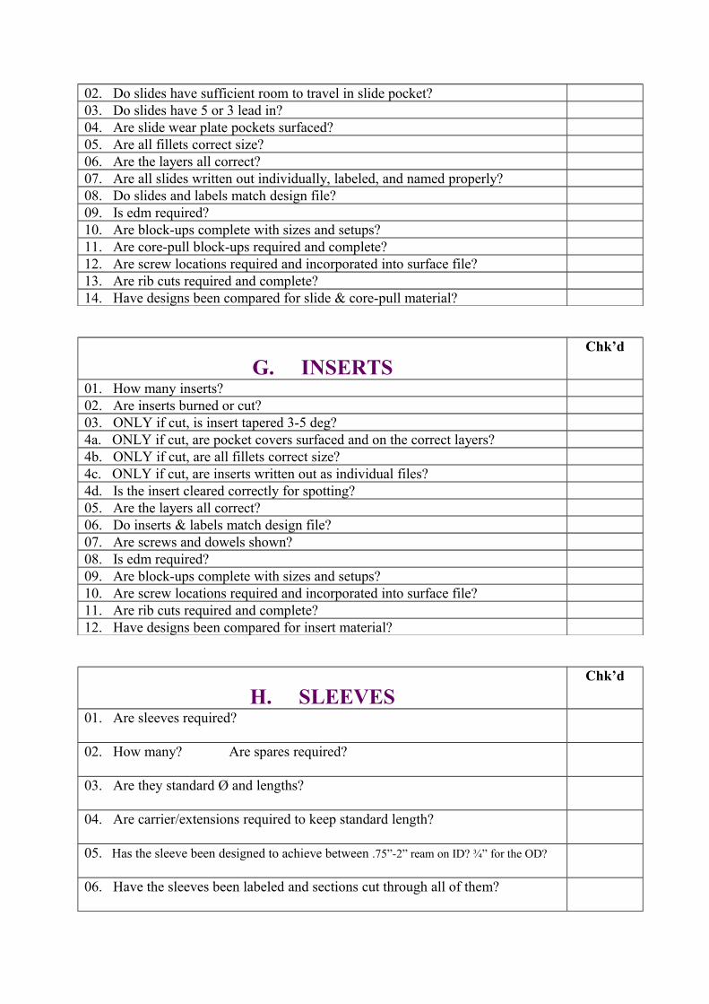
02. Do slides have sufficient room to travel in slide pocket? 03. Do slides have 5 or 3 lead in? 04. Are slide wear plate pockets surfaced? 05. Are all fillets correct size? 06. Are the layers all correct? 07. Are all slides written out individually, labeled, and named properly? 08. Do slides and labels match design file? 09. Is edm required? 10. Are block-ups complete with sizes and setups? 11. Are core-pull block-ups required and complete? 12. Are screw locations required and incorporated into surface file? 13. Are rib cuts required and complete? 14. Have designs been compared for slide & core-pull material?
G. INSERTSChk’d
01. How many inserts? 02. Are inserts burned or cut? 03. ONLY if cut, is insert tapered 3-5 deg? 4a. ONLY if cut, are pocket covers surfaced and on the correct layers? 4b. ONLY if cut, are all fillets correct size? 4c. ONLY if cut, are inserts written out as individual files? 4d. Is the insert cleared correctly for spotting? 05. Are the layers all correct? 06. Do inserts & labels match design file? 07. Are screws and dowels shown? 08. Is edm required? 09. Are block-ups complete with sizes and setups? 10. Are screw locations required and incorporated into surface file? 11. Are rib cuts required and complete? 12. Have designs been compared for insert material?
H. SLEEVESChk’d
01. Are sleeves required?
02. How many? Are spares required?
03. Are they standard Ø and lengths?
04. Are carrier/extensions required to keep standard length?
05. Has the sleeve been designed to achieve between .75”-2” ream on ID? ¾” for the OD?
06. Have the sleeves been labeled and sections cut through all of them?
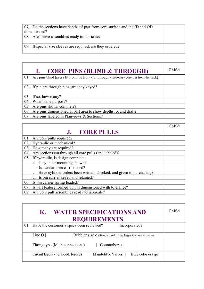
07. Do the sections have depths of part from core surface and the ID and OD dimensioned? 08. Are sleeve assemblies ready to fabricate?
09. If special size sleeves are required, are they ordered?
I. CORE PINS (BLIND & THROUGH) Chk’d
01. Are pins blind (press fit from the front), or through (stationary core pin from the back)?
02. If pin are through pins, are they keyed?
03. If so, how many? 04. What is the purpose?05. Are pins shown complete?06. Are pins dimensioned at part area to show depths, ø, and draft?07. Are pins labeled in Planviews & Sections?
J. CORE PULLSChk’d
01. Are core pulls required?02. Hydraulic or mechanical? 03. How many are required?04. Are sections cut through all core pulls (and labeled)?05. If hydraulic, is design complete: a. Is cylinder mounting shown? b. Is standard pin carrier used? c. Have cylinder orders been written, checked, and given to purchasing? d. Is pin carrier keyed and retained?06. Is pin carrier spring loaded?07. Is part feature formed by pin dimensioned with tolerance?08. Are core pull assemblies ready to fabricate?
K. WATER SPECIFICATIONS AND REQUIREMENTS
Chk’d
01. Have the customer’s specs been reviewed? Incorporated?
Line Ø | | Bubbler size ø (Standard std. 1 size larger than water line ø)
Fitting type (Main connections) | Counterbores |
Circuit layout (i.e. flood, forced) | Manifold or Valves | Hose color or type
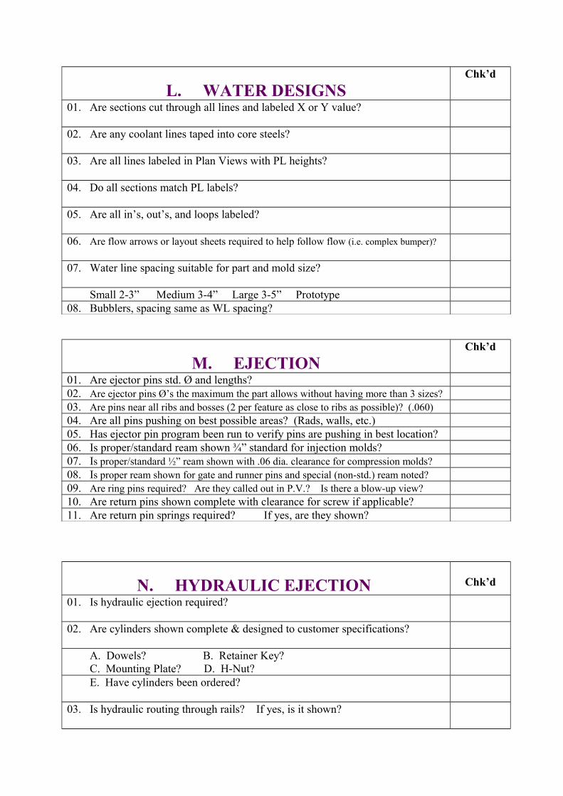
L. WATER DESIGNSChk’d
01. Are sections cut through all lines and labeled X or Y value?
02. Are any coolant lines taped into core steels?
03. Are all lines labeled in Plan Views with PL heights?
04. Do all sections match PL labels?
05. Are all in’s, out’s, and loops labeled?
06. Are flow arrows or layout sheets required to help follow flow (i.e. complex bumper)?
07. Water line spacing suitable for part and mold size?
Small 2-3” Medium 3-4” Large 3-5” Prototype 08. Bubblers, spacing same as WL spacing?
M. EJECTIONChk’d
01. Are ejector pins std. Ø and lengths?02. Are ejector pins Ø’s the maximum the part allows without having more than 3 sizes? 03. Are pins near all ribs and bosses (2 per feature as close to ribs as possible)? (.060)04. Are all pins pushing on best possible areas? (Rads, walls, etc.)05. Has ejector pin program been run to verify pins are pushing in best location?06. Is proper/standard ream shown ¾” standard for injection molds?07. Is proper/standard ½” ream shown with .06 dia. clearance for compression molds?08. Is proper ream shown for gate and runner pins and special (non-std.) ream noted?09. Are ring pins required? Are they called out in P.V.? Is there a blow-up view?10. Are return pins shown complete with clearance for screw if applicable?11. Are return pin springs required? If yes, are they shown?
N. HYDRAULIC EJECTION Chk’d
01. Is hydraulic ejection required?
02. Are cylinders shown complete & designed to customer specifications?
A. Dowels? B. Retainer Key? C. Mounting Plate? D. H-Nut? E. Have cylinders been ordered?
03. Is hydraulic routing through rails? If yes, is it shown?

04. Are rest buttons located directly next to hydraulic cylinders?
05. Are limit switches shown & protected?
O. MISCELLANEOUS Chk’d
01. Are standoffs required/shown?
02. Are safety straps shown?
03. Has all plate work been written up, checked, and given to purchasing department?
P. EJECTOR BOX Chk’d
01. Knock outs work for customer’s press?
02. Knock outs work for tryout press?
03. Knock out clearance size 2.25 Ø clearance or 1.25 Ø clearance?
04. Knock out threads called out?
05. Rest buttons designed to Standard std?
06. Rest button under return pins and sprue pins?
07. Rest buttons 6-8” apart on small molds and 8-10” apart on large molds?
08. Are ejector screws required for pin plate?
09. Is .50 Ø jack screw shown on or near CL?
10. Are .50 Ø dowels shown on CL?
11. Are forward stops required? If yes,
Is there only 4?
Are they near K.O. and hydraulic ejection cylinders?
12. Are they support designed?
13. Do support have ½” Ø socket head cap screw?

14. Is the ejector guide pin assembly to Standards?
Is the ejector guide pin assembly design complete?
15. Are handling holes shown & the same size if possible in all of the following components? a. Top of ejector plate?
b. Top or retainer plate?
c. Top of clamp plate (over 60” also in ends)?
d. Ends of rails?
16. If quick kickers are required, are they designed?
17. Is there clearance for lifter rod access?
18. Are bolt holes required? If so, is design complete?
19. Does clamp plate require valve gate manifold accommodations?
a. Pockets for valve gate cylinders?
b. Channels for valve gate plumbing?
c. Is water required in clamp plate for valve gate cooling?
20. Is standard H-Nut used for hydraulic ejection?
21. Is all hydraulic plumbing shown?
a. Main ins and outs. (Type? Location?)
b. Are flow dividers required?
22. Is manifold electrical designed to customer specs?
23. Are plaques and schematics required? If yes, are they designed?
a. Water?
b. Hydraulics?
c. Electrical?
d. I.D. tab? (ALWAYS REQUIRED)
e. Any special purpose plaques?
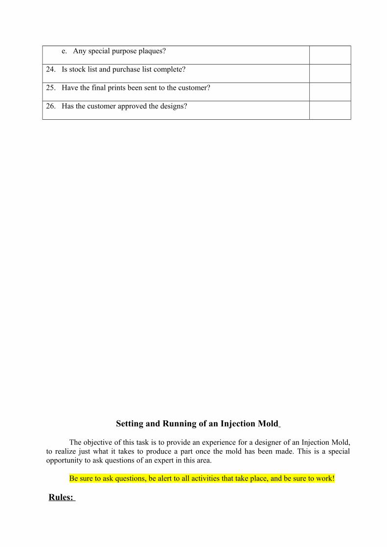
24. Is stock list and purchase list complete?
25. Have the final prints been sent to the customer?
26. Has the customer approved the designs?
Setting and Running of an Injection Mold
The objective of this task is to provide an experience for a designer of an Injection Mold, to realize just what it takes to produce a part once the mold has been made. This is a special opportunity to ask questions of an expert in this area.
Be sure to ask questions, be alert to all activities that take place, and be sure to work!
Rules:
DO Not: Touch or do anything, until you are told it is OK by the instructor or Manager.
DO:Make an effort to make the process as efficient as possible. Make sure that you get a part/runner.
Note:
Bring Safety glasses, and, you may get a little grease on you clothesso dress appropriately.
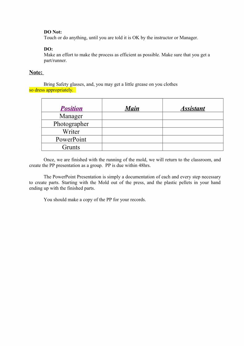
Position Main AssistantManager
Photographer
Writer
PowerPoint
Grunts
Once, we are finished with the running of the mold, we will return to the classroom, and create the PP presentation as a group. PP is due within 48hrs.
The PowerPoint Presentation is simply a documentation of each and every step necessary to create parts. Starting with the Mold out of the press, and the plastic pellets in your hand ending up with the finished parts.
You should make a copy of the PP for your records.