Embed Size (px)
Citation preview

DESIGN OF A S PERPU51AKAANUMP ON (HARDWARE)
0000080357
MOHD YASHIM WONG PAUL TZE
Report submitted in partial fulfillment of the requirements for the award of the degree of
Bachelor of Manufacturing Engineering
Faculty of Manufacturing Engineering
UNIVERSITI MALAYSIA PAHANG
SEPTEMBER 2013

ABSTRACT
The Powered Exoskeleton is an electromechanical structure worn by an operator, matching
the shape and functions of the human body. Exoskeletons supplements the function of the
human limb by augmenting its strength, agility and endurance or at least by supplying the
activation energy required to initiate the limb's movements. This project provides the
detailed steps on the design of powered exoskeleton structures and considerations involved
when designing it. Considerations such as ergonomics, loadings and actuator capabilities,
costs and manufacturability were taken into consideration during the early steps. To be
kinematically compatible with human walking motion, gait analysis or the study of human
walking have been performed. Kinovea which is a video motion analysis was used to
capture all the walking data. For actuation, two actuators; Pneumatic Muscle Actuator and
Pneumatic Cylinders were tested for compliant actuation. Solidworks is used to design the
frame and to perform Finite Element Analysis as well as a motion simulator to check
compatibility with human motion. All data were compared taking actual gait data as
benchmark.
V
ABSTRAK
Exoskeleton berkuasa adalah sejenis struktur elektromekanikal yang di pakai oleh seorang
operator. la mempunyai ciri-ciri yang mirip bentuk dan fungsi badan manusia. Exoskeleton
membantu pergerakan manusia dengan meningkatkan kekuatan, kelajuan dan ketangkasan
atau dengan sekurang-kurangñya menyumbangkan tenaga pengaktifan bagi satu gerakan.
Projek mi membentangkan fasa-fasa secara terperinci mengenai proses reka bentuk struktur
exoskeleton berkuasa dan pertimbangan yang di buat ketika proses tersebut di buat.
Pertimbangan seperti ergonomika, bebanan kebolehan actuator, kos serta kebolehrnesinan
di ambil kira pada peringkat pengkonsepan. Untuk menjadi serasi dari segi kinematic
dengan pergerakan manusia, analisa gait atau analisa pergerakan kaki manusia ketika
berjalan di buat. Kinovea di gunakan untuk merekod segala data daripada video. Dari segi
aktuator, dua aktuator telah di kaji iaitu Aktuator Otot Pneumatik dan Omboh Pneurnatik.
Solidworks di gunakan untuk mereka bentuk rangka exoskeleton dan juga untuk
menjalankan Analisa Unsur Terhingga serta untuk simulasi pergerakan untuk
membandingkan keserasian dengan gerak geri berjalan manusia. Kesemua data yang di
peroleh daripada simulasi pergerakan dibandingkan dengan data sebenar gerakan j alan kaki
sebenar.
Vi
TABLE OF CONTENTS
Page
SUPERVISOR'S DECLARATION
STUDENT'S DECLARATION
ACKNOWLEDGEMENTS iv
ABSTRACT V
ABSTRAK vi
TABLE OF CONTENTS vii
LIST OF TABLES viii
LIST OF FIGURES xi
LIST OF SYMBOLS xii
CHAPTER 1 INTRODUCTION 1
1.1 Project Background 1
1.2 Aims and Objectives 3
1.3 Problem Statement 3
1.4 Project Scopes 4
CHAPTER 2 LITERATURE REVIEW 5
2.1 Introduction 5
2.2 Human Gait Analysis 5
2.3 Power Requirements during walking 9
2.4 Effect of Walking Forces towards Metabolic Rate 17
2.5 Exoskeleton Frame Design 18
VII
2.5.1 Types of Exoskeleton 17

VII
CHAPTER 3
2.5.2 Design Architecture 17
2.5.3 Degrees of Freedom 21
2.6 Actuation 24
2.6.1 Joint Actuation Selection 24
2.6.2 Actuator Type Selection 24
METHODOLOGY 30
3.1 Introduction 31
3.2 Clinical Gait Analysis Setup 32
3.3 Mechanical Design 29
3.3.1 Actuator Selection 29
3.3.2 Actuator Positioning 31
3.3.3 Frame Design 34
CHAPTER 4 Results and Discussion 36
4.1 Introduction 36
4.2 Actuator Test Results 36
4.3 Gait Analysis Results 37
4.4 Motion Analysis Results 44
4.4.1 Hip Angular Velocity 45
4.4.2 Knee Angular Velocity 46
4.4.3 Ankle Angular Velocity 47
4.5 Finite Element Analysis Results 49
4.5.1 Thighs FEA Results 49
4.5.2 Lower Leg FEA Results 51
VII
4.5.3 Feet FEA Results 55
CHAPTER 5 Conclusion 57
5.1 Introduction 57
5.2 Suggestions for Future Work 58
REFERENCES
APPENDICES
Al Raw Gait Analysis Data - Linear Velocity 61
A2 Raw Gait Analysis Data - Angular Velocity 62
VIII
LIST OF TABLES
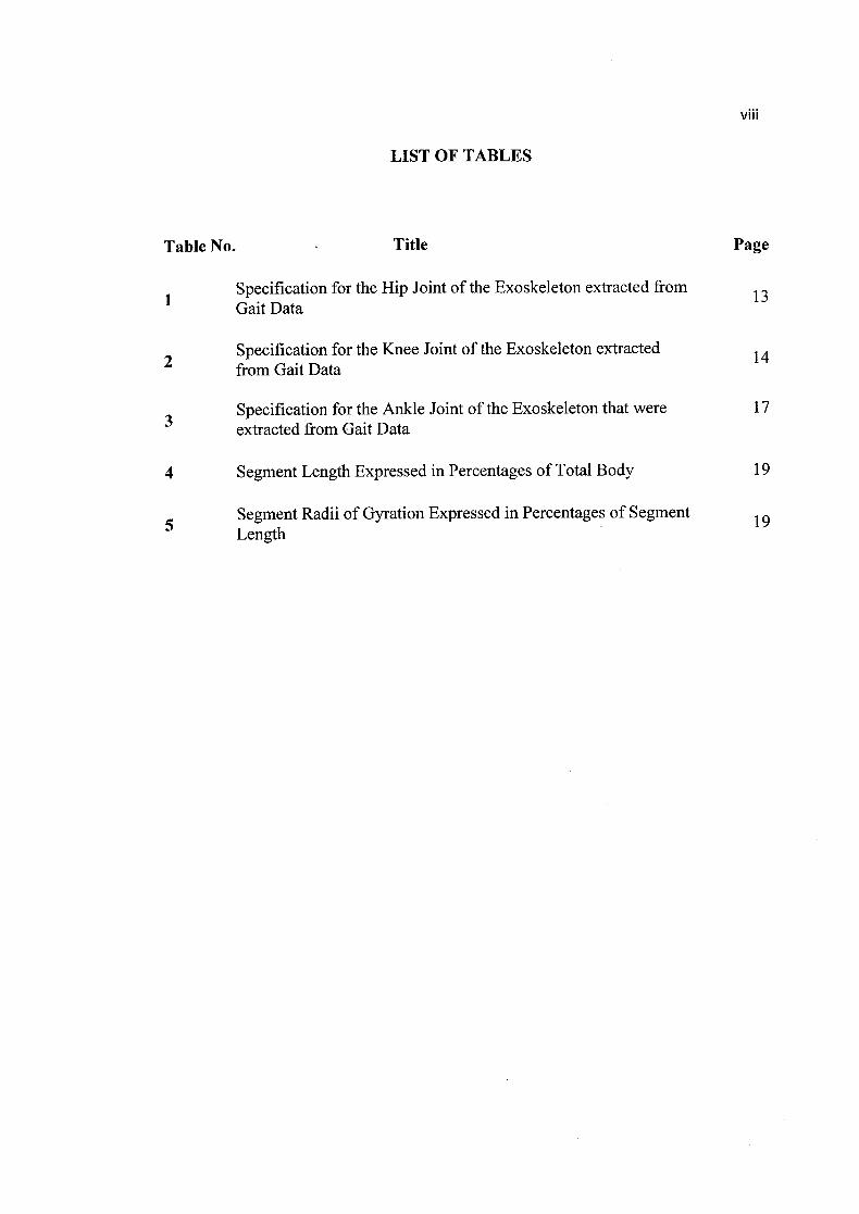
Table No. Title Page
Specification for the Hip Joint of the Exoskeleton extracted from 13 Gait Data
2Specification for the Knee Joint of the Exoskeleton extracted 14 from Gait Data
3Specification for the Ankle Joint of the Exoskeleton that were 17 extracted from Gait Data
4 Segment Length Expressed in Percentages of Total Body 19
5Segment Radii of Gyration Expressed in Percentages of Segment 19 Length

xi
LIST OF FIGURES
Figure No. Title Page
1 Reference Plane of Body in Standard Anatomic Position 6
2 Description of Direction of Joint Motion 6
3Nomenclature for Movement of Ankle, Toes, Hindfoot and 7 Forefoot
4 Sign Convention Used For Joint Angles 7
5 Phases and Postion of Legs in Gait Cycle 8
6 Timings of Double and Single Support During Gait Cycle 9
7 Significant Regions of Positive and Negative Work in Walking 10
8 Hip Joint Power Profile Scaled for a 135kg Person as a Function 12 of the Gait Cycle
9 Hip Angle Versus Hip Torque for Walking Speed of 0.8m/s 13
10 Knee Joint Power Profile Scaled for a 60kg Person as a Function 14 of Gait Cycle
11 Plot of Knee Angle Versus Knee Torque for the Walking Cycle 15
12Ankle Joint Power Profile Scaled for a 60kg Person as a 16 Function of Gait Cycle
13 Plot of Knee Angle Versus Knee Torque for the Walking Cycle 17
14 Effects of Applied Horizontal Force towards Metabolic Rate 18
15 Springbuck Running Shoes 20
16 Bearing Surfaces of a Hip 22
17 Human Knee Joint 23

XII
18 Human Ankle Joint 23
19 Apparatus Setup for Gait Analysis 27
20 Motion Analysis using Kinovea 28
21 Pneumatic Muscle Actuator (PMA) Cross Section View 29
22 Pneumatic Cylinder 30
23 Experiment Setup for Actuator Testing 30
24 Experiment Setup for Actuator Testing 30
25 Simplified Free-Body Diagram for Exoskeleton Frame 32
26 Motion Analysis using Solidworks Motion 34
Preliminary Finite Element Analysis (FEA) on Simplified Frame 35 27 Used in Motion Simulation with 8769 times Deformation Scale
28 Actuator Test Results 36
29 Velocity Profile For Hip, Knee and Ankle from Gait Analysis 37
30Angular Displacement Profiles for Hip, Knee and Ankle from 38 Gait Analysis
31 Angular Velocity Profiles for Hip, Knee and Ankle from Gait 38 Analysis
32 Angular Acceleration Profiles for Hip, Knee and Ankle from 39 Gait Analysis
33 Hip Torque Plotted against Joint Angle from Dynamic Equations 42
34 Knee Torque Plotted against Joint Angle from Dynamic 43 Equations
35 Ankle Torque Plotted against Joint Angle from Dynamic 43 Equations
36 Motion Analysis for Exoskeleton Frame 44
XIII
37 Comparison of Hip Angular Velocities between Gait Analysis 45
and Motion Simulation
38 Comparison of Knee Angular Velocities between Gait Analysis 46 and Motion Simulation
39 Comparison of Ankle Angular Velocities between Gait Analysis 47 and Motion Simulation
40 Actuator 1 Results from Simulation 48
41 Actuator 2 Results from Simulation 48
42 Von Mises Stress Results for Thigh Frame 49
43 Displacement Results for Thigh Frame 50
44 Factor of Safety Results for Thigh Frame 50
45 Von Mises Stress Results for Lower Leg Part A 51
46 Displacement Results for Lower Leg Part A 52
47 Factor of Safety Results for Lower Leg Part A 52
48 Von Mises Stress Results for Lower Leg Part B 53
49 Displacement Results for Lower Leg Part B 54
50 Factor of Safety Results for Lower Leg Part B 54
51 Von Mises Stress Results for Feet Base 55
52 Displacement Results for Feet Base 56
53 Factor of Safety Results for Feet Base 56

LIST OF SYMBOLS
FaiActuator force at location 1
Fa2Actuator force at location 2
Fa3Actuator force at location 3
m1 Combined mass' at thighs
M2Combined mass at leg
M3Combined mass at feet
11 Thigh length
12 Leg length
1 3 Feet length
0 Angular displacement
Angular velocity
Angular acceleration
g Gravitational acceleration
Torque
I Moment of Inertia
XII

CHAPTER 1
INTRODUCTION
1.1 Background
The powered exoskeleton is an electromechanical structure worn by an operator, matching the shape
and functions of human body (Anam, K., & Al-Jumaily, A. A., 2012). Exoskeletons supplements the
function of the human limbs by augmenting its strength, agility and endurance or at least by supplying the
activation energy required to initiate the limb's movements. Different from conventional robotics, there is
a close physical interaction between the exoskeleton and the human wearer. Close interaction means the
wearer controls the exoskeleton via physical contact with sensors. This is the reverse of master-slave
configurations, where there is no physical contact between the slave and the human operator, which are
remote from one another (Pons, J. L., 2008). According to this concept, the exoskeleton functions as both
an input device (by obtaining signals from wearer and moving to desired location) as well as a force
feedback device (by providing haptic interactions between the exoskeleton and its environment).
The application of exoskeleton ranges from military use to rehabilitative use. In military applications,
Matthias, H., (2007) states that exoskeletons increases the performance of soldiers through:
Increasing payload: ability to carry or fire power, supplies, ammunition and heavier armour
increasing the survival chance of a soldier after a direct hit or explosion
Increasing speed and range: enhance ground reconnaissance and battle space coverage
Increasing strength: ability to operate larger calibre weapons and withstand recoil as well as better
obstacle clearance
1
2
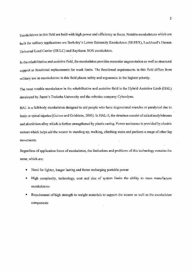
Exoskeletons in this field are built with high power and efficiency as focus. Notable exoskeletons which are
built for military applications are Berkeley's Lower Extremity Exoskeleton (BLEEX), Lockheed's Human
Universal Load Carrier (HULC) and Raytheon XOS exoskeleton.
In the rehabilitative and assistive field, the exoskeleton provides muscular augmentation as well as structural
support as functional replacements for weak limbs. The functional requirements in this field differs from
military use as exoskeletons in this field places safety and ergonomic in the highest priority.
The most notable exoskeleton in the rehabilitative and assistive field is the Hybrid Assistive Limb (HAL)
developed by Japan's Tsukuba University and the robotics company Cyberdyne.
HAL is a full-body exoskeleton designed to aid people who have degenerated muscles or paralyzed due to
brain or spinal injuries (Guizzo and Goldstein, 2005). In HAL-5, the structure consist of nickel molybdenum
and aluminium alloy which is further strengthened by plastic casing. Power assistance is provided by electric
motors which helps aid the wearer in standing up, walking, climbing stairs and perform a range of other leg
movements.
Regardless of application focus of exoskeleton, the limitations and problems of this technology remains the
same, which are:
• Need for lighter, longer lasting and faster recharging portable power
• High complexity, technology, cost and size of system limits the ability to mass manufacture
exoskeletons
• Requirement of high strength to weight materials to support the wearer as well as the exoskeleton
components
3
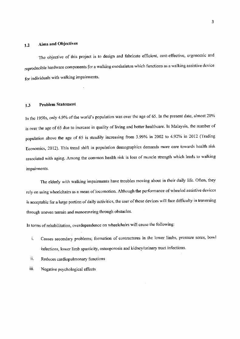
1.2 Aims and Objectives
The objective of this project is to design and fabricate efficient, cost-effective, ergonomic and
reproducible hardware components for a walking exoskeleton which functions as a walking assistive device
for individuals with walking impairments.
1.3 Problem Statement
In the 195 0s, only 4.9% of the world's population was over the age of 65. In the present date, almost 20%
is over the age of 65 due to increase in quality of living and better healthcare. In Malaysia, the number of
population above the age of 65 is steadily increasing from 3.99% in 2002 to 4.92% in 2012 (Trading
Economics, 2012). This trend shift in population demographics demands more care towards health risk
associated with aging. Among the common health risk is loss of muscle strength which leads to walking
impairments.
The elderly with walking impairments have troubles moving about in their daily life. Often, they
rely on using wheelchairs as a mean of locomotion. Although the performance of wheeled assistive devices
is acceptable for a large portion of daily activities, the user of these devices will face difficulty in traversing
through uneven terrain and manoeuvring through obstacles.
In terms of rehabilitation, overdependence on wheelchairs will cause the following:
i. Causes secondary problems; formation of contractures in the lower limbs, pressure sores, bowl
infections, lower limb spasticity, osteoporosis and kidney/urinary tract infections.
ii. Reduces cardiopulmonary functions
iii. Negative psychological effects

4
1.4 Project Scopes
This project is focused on the design and fabrication of a wearable exoskeleton mechanical components as
well as hardware selection based on human biomechanics data. The project scope is broken down into the
following:
a. Clinical Gait Analysis
b. Design and motion simulation of exoskeleton frame
c. Selection and assembly of mechanical elements
d. Fabrication of frame and mechanical elements
e. Live test run of exoskeleton
E Performance evaluation

5
CHAPTER 2
LITERATURE REVIEW
2.1 Introduction
In this chapter, general concepts and terminology of walking will be introduced. This includes
discussion on previous works comprising the analysis, mechanics and description of stages involved in
walking. Methods employed during the design phase of various previous works on exoskeleton will be
reviewed and adapted to this project. In the analysis part of this chapter, torque, power, velocity and angle
of normal walking, walking with load and walking with exoskeletons designed by previous papers will be
reviewed and be used as a benchmark to this project's findings.
2.2 Human Gait Analysis
Human gait analysis is defined as the systematic study of human walking. Understanding the human
gait is not just important for deciding the kinematic and dynamic architecture but also for the proper
selection of powered joints and exoskeleton ergonomics as well as specification for actuation components
and its placement. It is important that the design of the exoskeleton mimics the kinematics and dynamics of
walking so that it does not cause the walker to alter their gait. This is because gait changes have been shown
to increase energy expended during locomotion (T. A. McMahon, G. Valiant, E. C. Frederick, 1987).
By definition, walking is an alternating repetitive sequence of limb motion to move forward while
simultaneously maintaining stance stability (C.J Walsh, 2003). The cyclical process of events during gait is
known as the gait cycle. It starts and ends the moment when one foot comes into contact with the ground,

lane
usually termed heel strike (Perry, 1992). The analysis of walking is three dimensional but in this final year
project, the focus is on the sagittal plane as the largest motions, torques and powers are in this plane. (H.
Kazeeroni, 2005)
Figure 2.1: Reference planes of body in standard anatomic position (Michael, W. Whittle., 2007)
Since the key focus is on the Sagittal Plane, the motions that will be discussed throughout this thesis are
Extension (positive direction) and Flexion (negative direction).
Figure 2.2: Description of direction of joint motions (Michael, W. Whittle., 2007).
7
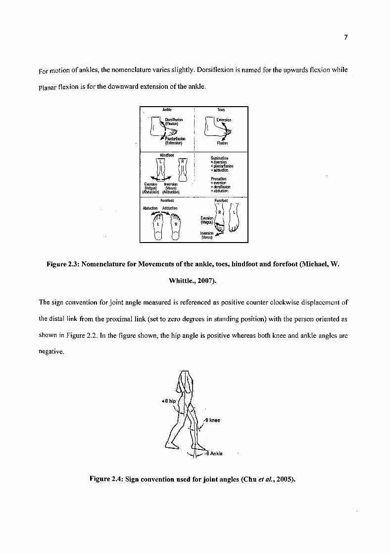
For motion of ankles, the nomenclature varies slightly. Dorsiflexion is named for the upwards flexion while
Planar flexion is for the downward extension of the ankle.
Ankle Toes
Extension
Plantarfienon (Extension) Fledon
HindfootSipinstion
inversion + plantarfiexion + adduction
Eversion Inversion gus) "'r us uction) (Addudion)
Pro nation aversion
+ dorsifiexion + abduction
Forefoot
Abduction Adduction
Forefoot
L EOfl (Valgus) ) ç
Inversion (Varus)
Figure 2.3: Nomenclature for Movements of the ankle, toes, hindfoot and forefoot (Michael, W.
Whittle., 2007).
The sign convention for joint angle measured is referenced as positive counter clockwise displacement of
the distal link from the proximal link (set to zero degrees in standing position) with the person oriented as
shown in Figure 2.2. In the figure shown, the hip angle is positive whereas both knee and ankle angles are
negative.
Figure 2.4: Sign convention used for joint angles (Chu et al., 2005).
8
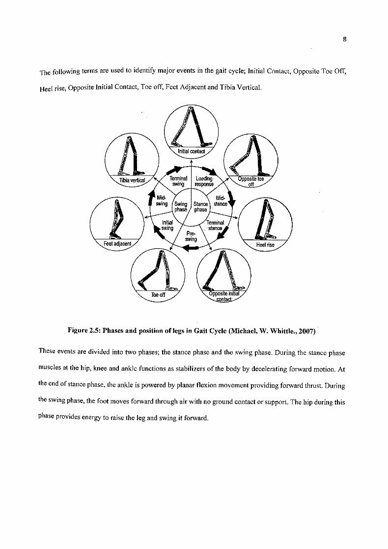
The following terms are used to identify major events in the gait cycle; initial Contact, Opposite Toe Off,
Heel rise, Opposite Initial Contact, Toe off, Feet Adjacent and Tibia Vertical.
Initial contact
Tibia ti/'/ Terminal Loading swing response
g Swing Stanc^ stance
phase phase
Initial Terminal
sMng
Pre-
stance
Feet adjaoe tswing
Toe off
Figure 2.5: Phases and position of legs in Gait Cycle (Michael, W. Whittle., 2007)
These events are divided into two phases; the stance phase and the swing phase. During the stance phase
muscles at the hip, knee and ankle functions as stabilizers of the body by decelerating forward motion. At
the end of stance phase, the ankle is powered by planar flexion movement providing forward thrust. During
the swing phase, the foot moves forward through air with no ground contact or support. The hip during this
phase provides energy to raise the leg and swing it forward.

Left leg
Right le
9
Left Left initial Left toe off contact Timn toe off
Right initial Right Right initial contact toe off contact
Figure 2.6: Timings of double and single support during gait cycle (Michael, W. Whittle., 2007)
During each gait cycle, there are two single support and two double support periods. The stance phase at
average takes up 60% of the total cycle while the swing phase takes about 40%. The double support phase
only takes up 10% each during gait cycle. This diagram is only valid for slow walking and is inaccurate at
higher walking speeds. As velocity is increased, stance phase duration is reduced, whereas swing phase
duration increases. (Sheila A. Dugan, Krishna P. Bhat, 2005)
2.3 Power Requirements during Walking
In the human body, muscles contracts to provide locomotion or force. Voluntary muscular
contractions can be categorized into the followings based on their length changes or force level:
1. Concentric Contractions
Force generated by muscle is sufficient to overcome resistance, and muscle shortens as it contracts.
Positive work is performed during this type of motion movement which provides limb acceleration
and powers such as hip flexion during pre-swing.

I.
10
2. Eccentric Contractions
Force generated is insufficient to overcome external load and muscle fibres lengthens as they
contract. Eccentric movements are generally for decelerating limbs for movements. Negative work
is performed during this type of contraction. Energy is stored by the limb while resisting pull of
gravity.
3. Isometric Contractions
Muscle remains the same length as before contraction. The muscle force exactly matches the
external load. This type of contractions occur during movements that involve holding a position
without moving. In walking, many muscles contract isometrically to maintain upright posture
against gravity.
Positive Power . Negative Power• Figure 2.7 Significant regions of positive and negative work in walking (C.J. Walsh et aL,
2006).
Figure 2.7 shows significant regions of positive and negative power during human gait. The red and
blue circle indicates region of positive power and negative power at hip, knee and ankle during phases
in the gait cycle. A large portion of positive power during gait were generated from HI and H3 at the
hip and A2 at the ankle. The knee dissipate large amounts of energy during gait except at K2 region as
the body's center of mass is raised. During Al at ankle and H2 at hip, negative power is generated to
control the body's forward movement against gravity.
Power profiles of the .hip, ankle and knee in the sagittal plane were plotted (C.J. Walsh et al.,
2006) against data obtained from previously done Clinical Gait Analysis (A.J Van den Bogert, 2004; C.
Kirtley, 1998; J. Linskell, 1997). In their research (C.J. Walsh et al., 2006), they estimated that the
weight of the exoskeleton and the load it carries to be 60 kg and the human wearer to be of 75 kg. In
estimating torque and power requirements at hip joint of the exoskeleton, the normative data were scaled
to a 135 kg person. The torque vs. angle plots they used are obtained from CGA data (J. Linskell, 2006)
and is for walking speed of 0.8 m/s. The assumptions that were made in applying biomechanical gait
data to the exoskeleton design are:
I. The exoskeleton carries its own weight, power supply and payload.
2. Joint torques and joint powers scale linearly with mass. This assumption seems reasonable as
previous research shown that increase in load being carried is proportional to increase in
ground reaction forces (R. Lloyd, & C. B. Cooke, 2000)
3. Exoskeleton will not greatly affect the gait of the wearer.
I. Hip
Throughout normal gait, the human hip joint follows a roughly sinusoidal pattern with the thigh
flexed forward on heel strike and the hip moves through extension during the stance as body is
Pivoted at the ground, over the stance leg in a reverse pendulum-like motion. Positive power is
required on heel strike to raise the center of mass of the human over the stance leg.
11
H3
HI
N Kirtley (Your 1-12 - - - KirtIt, 1Ol1
12
200
150
100
50
a) 0 a-
0 I-50
-100
_1- "p0 10 20 30 40 50 60 70 80 90 IUC
% Gait Cycle
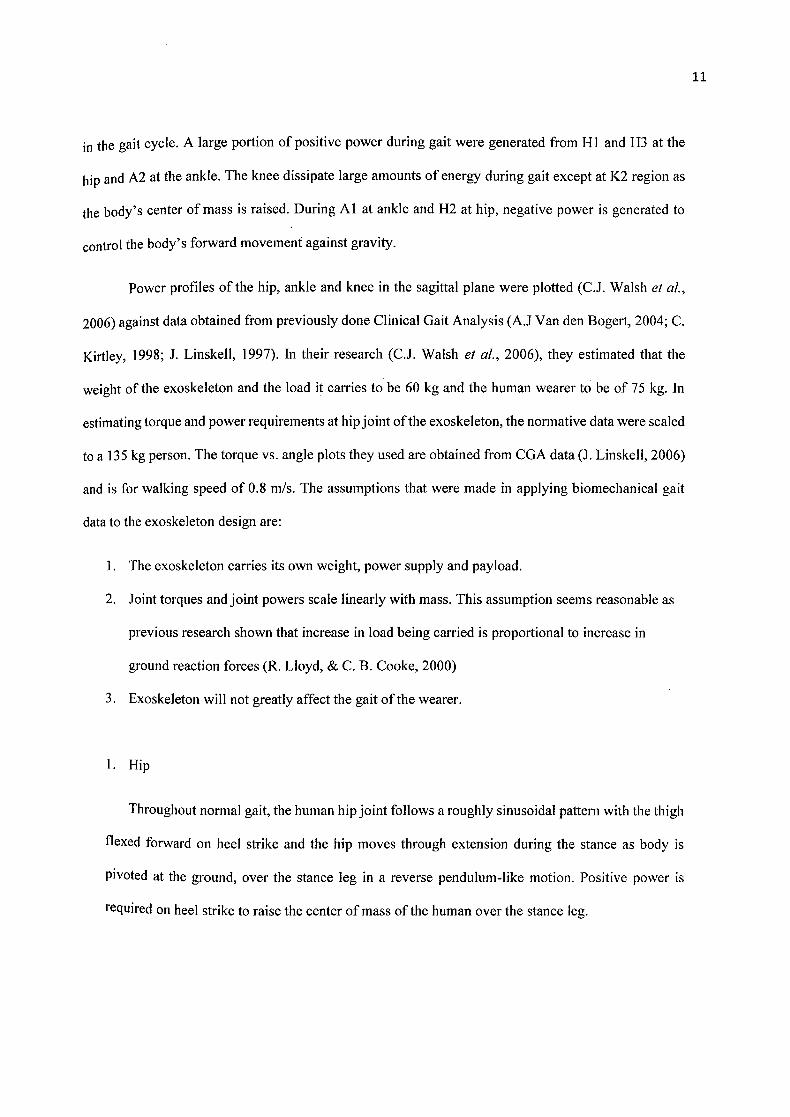
Figure 2.8: Hip joint power profile scaled for a 135kg person as a function of the gait cycle (C.J.
Walsh et al., 2006).
HI is a small region of positive powers which corresponds to backward movement of the leg (concentric
hip extension) during loading response. H2 is a region of negative power which corresponds to eccentric
hip flexion during mid-stance and H3 is a region of positive power, corresponding to concentric hip flexion
during pre-swing and initial swing.
13
• _________
Nmlrad
Extensio
4
**
* 4 4 4 *4
*
-10 -5 0 5 10 15 20 25 30 35
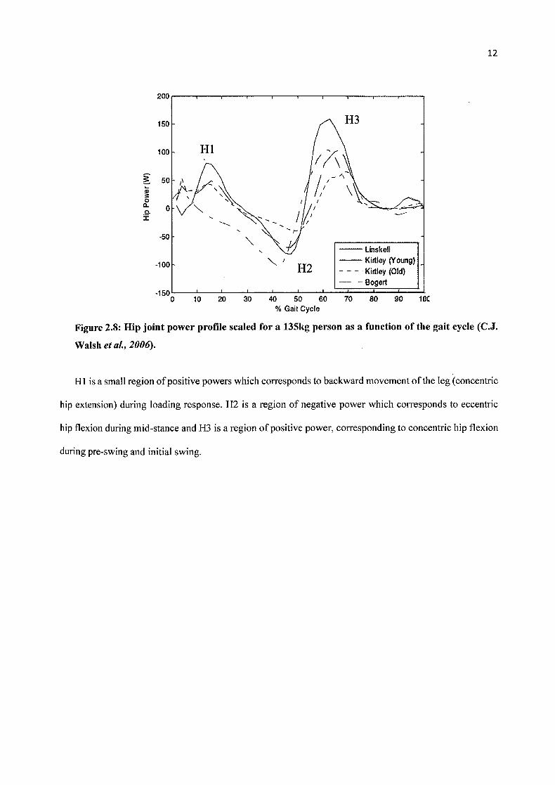
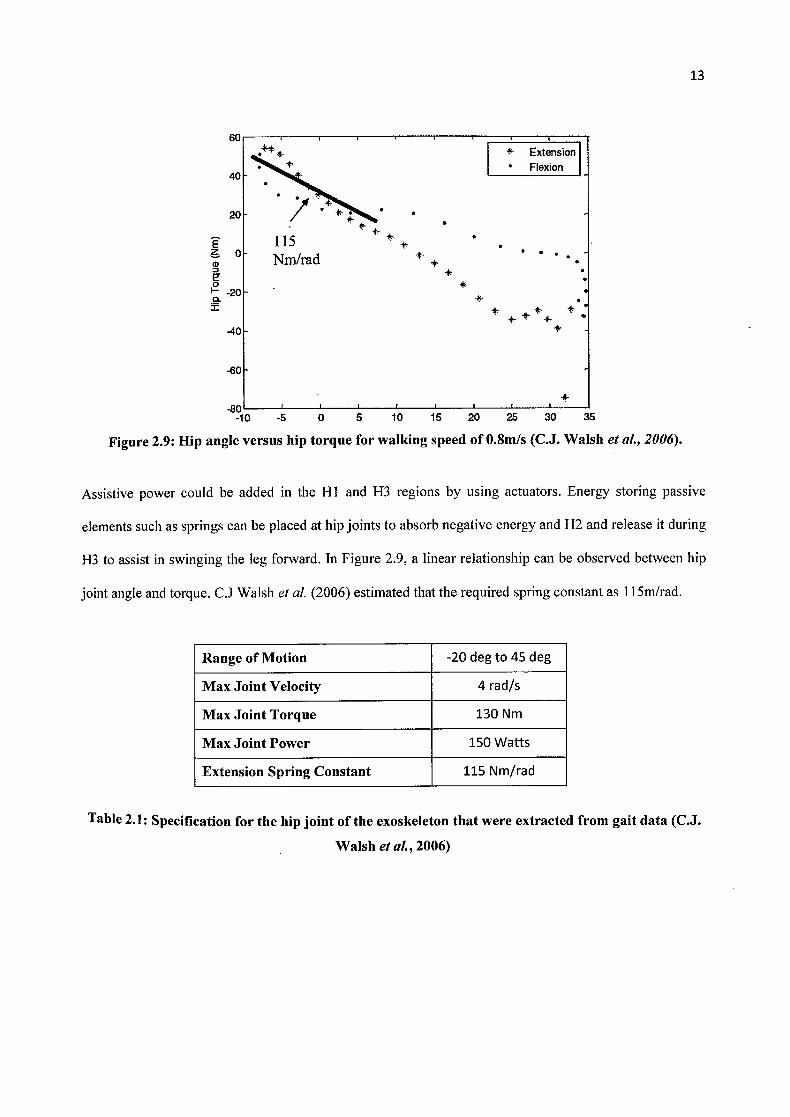
Figure 2.9: Hip angle versus hip torque for walking speed of 0.8m/s (C.J. Walsh et A. 2006).
Assistive power could be added in the Hi and H3 regions by using actuators. Energy storing passive
elements such as springs can be placed at hip joints to absorb negative energy and H2 and release it during
H3 to assist in swinging the leg forward. In Figure 2.9, a linear relationship can be observed between hip
joint angle and torque. CJ Walsh et al. (2006) estimated that the required spring constant as ii 5m/rad.
Range of Motion -20 deg to 45 deg
Max Joint Velocity 4 rad/s
Max Joint Torque 130 Nm
Max Joint Power 150 Watts
Extension Spring Constant 115 Nm/rad
Table 2.1: Specification for the hip joint of the exoskeleton that were extracted from gait data (C.J.
Walsh el aL, 2006)
60
40
20
E
-20
.40
-60