Embed Size (px)
Citation preview
Module T7
Power Flow
Read Module T7.
Work problems 1, 2, 3, 7 at end of Module T7.
Turn in on Tuesday, April 9.
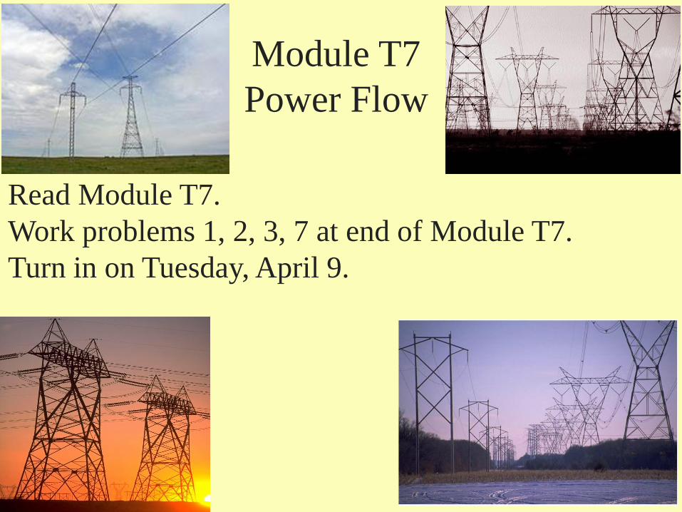
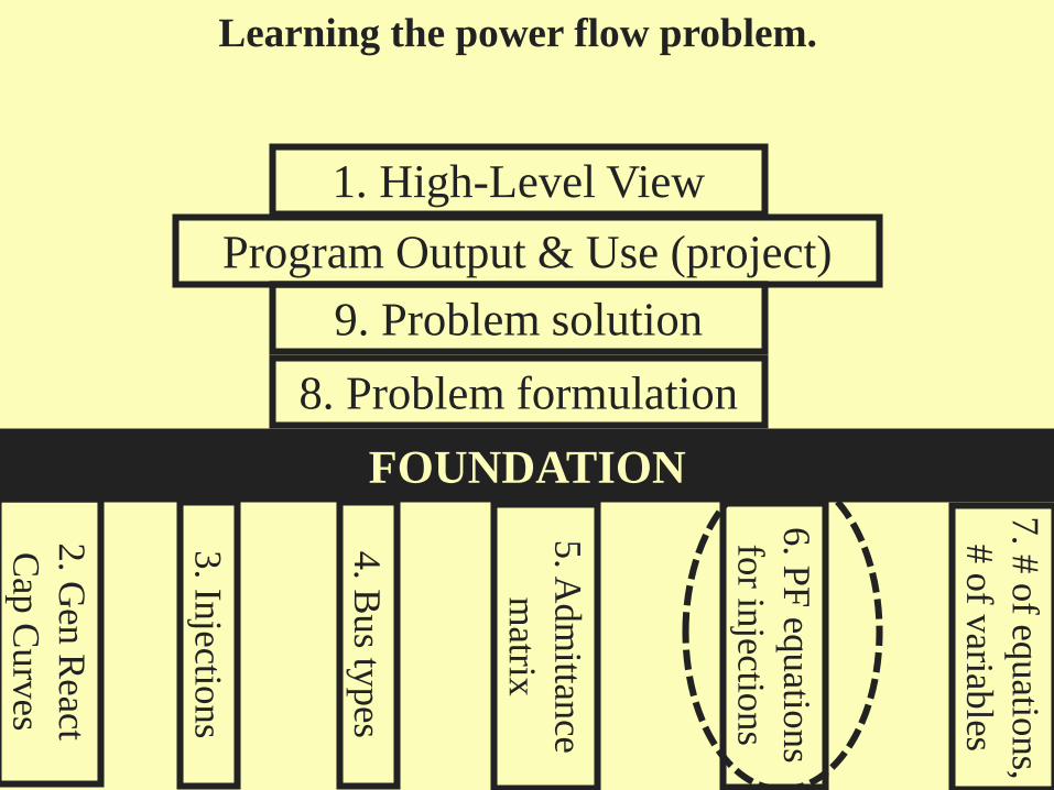
Learning the power flow problem.
1. High-Level View
Program Output & Use (project)
9. Problem solution
8. Problem formulation
FOUNDATION
2. G
en R
eact
Cap
Cu
rves
3. In
jection
s
4. B
us ty
pes
5. A
dm
ittance
matrix
6. P
F eq
uatio
ns
for in
jection
s
7. #
of eq
uatio
ns,
# o
f variab
les
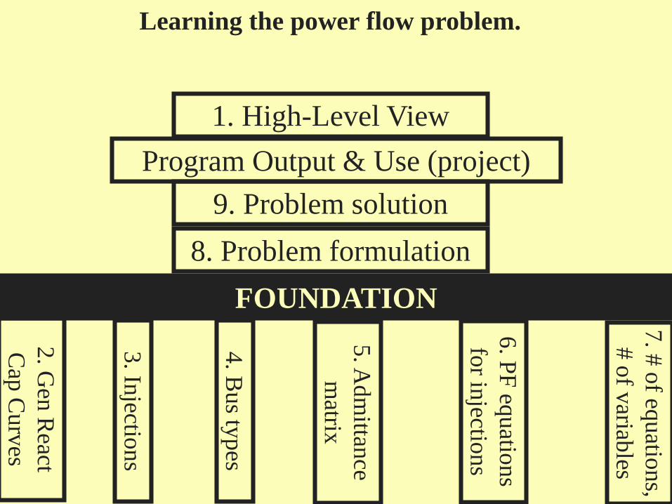
2. Gen reactive capability curve
P
Q
Field current limit due to field heating,enforced by overexcitation limiter on If.
Armature current limit due toarmature heating, enforced byoperator control of P and If.
Qmax
Qmin
Typical approximationused in powerflow programs.
Limit due to steady-state instability (small internal voltage E gives small |E||V|Bsin), and due to stator end-region heating from induced eddy currents, enforced by underexcitation limiter (UEL).
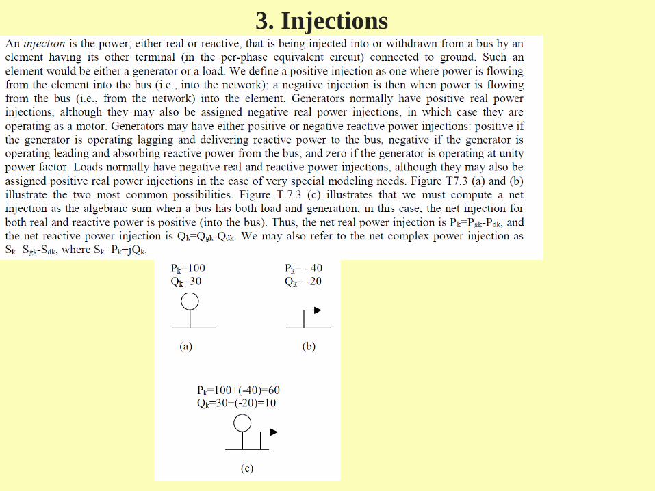
3. Injections

4. Bus types
First classification:
• Gen
• Load
• Both
2nd classification (in
terms of info known at
the buses).
What is possible info?
• V
• θ
• Pinj
• Qinj
Bus type PV (usually gen)
• Knowns:
• Pinj
• V
• Unknowns:
• Qinj
• θ
Bus type PQ (usually load)
• Knowns:
• Pinj
• Qinj
• Unknowns:
• V
• θ
4. Bus types
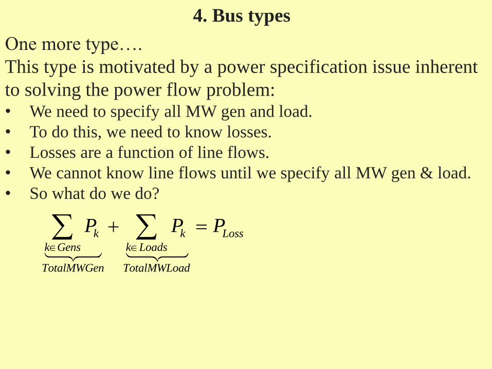
One more type….
This type is motivated by a power specification issue inherent
to solving the power flow problem:• We need to specify all MW gen and load.
• To do this, we need to know losses.
• Losses are a function of line flows.
• We cannot know line flows until we specify all MW gen & load.
• So what do we do?
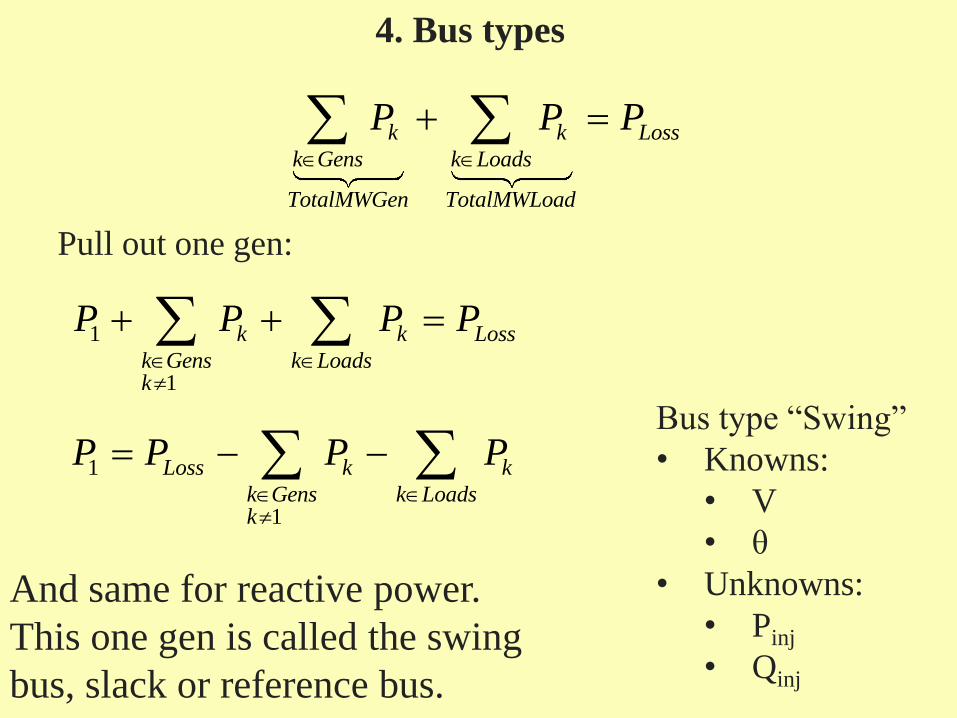
k k Loss
k Gens k Loads
TotalMWGen TotalMWLoad
P P P
4. Bus types
Bus type “Swing”
• Knowns:
• V
• θ
• Unknowns:
• Pinj
• Qinj
k k Loss
k Gens k Loads
TotalMWGen TotalMWLoad
P P P
Pull out one gen:
1
1
k k Loss
k Gens k Loadsk
P P P P
1
1
Loss k k
k Gens k Loadsk
P P P P
And same for reactive power.
This one gen is called the swing
bus, slack or reference bus.
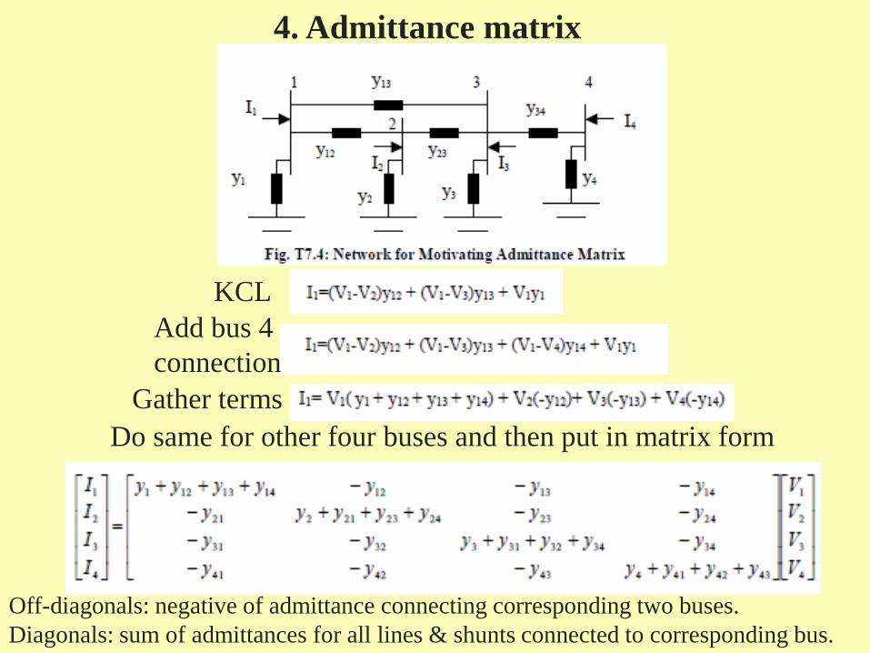
4. Admittance matrix
KCL
Add bus 4
connection
Gather terms
Do same for other four buses and then put in matrix form
Off-diagonals: negative of admittance connecting corresponding two buses.
Diagonals: sum of admittances for all lines & shunts connected to corresponding bus.
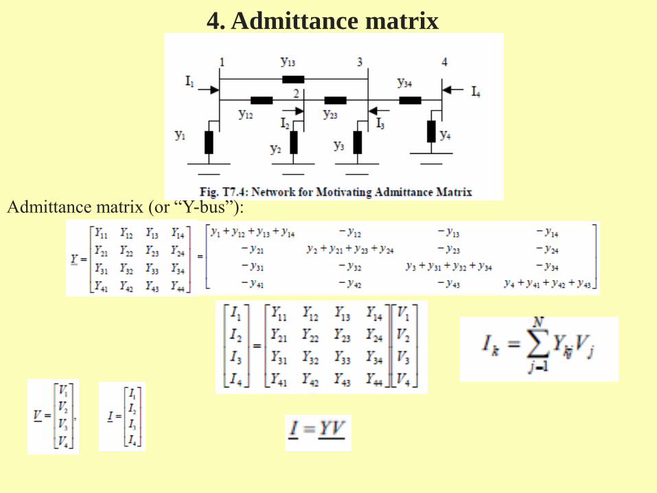
4. Admittance matrix
Admittance matrix (or “Y-bus”):
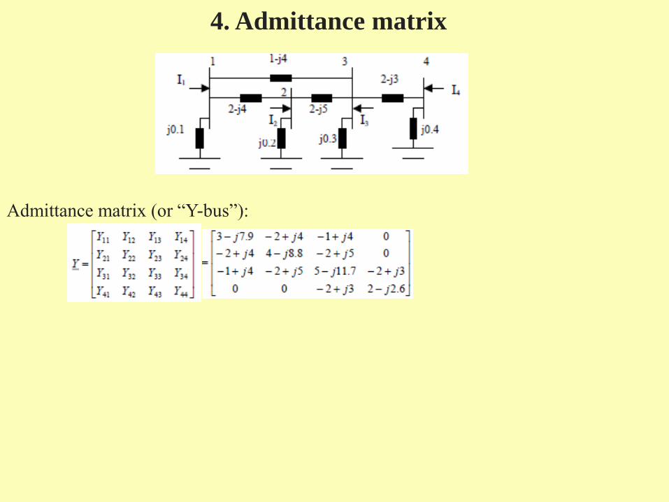
4. Admittance matrix
Admittance matrix (or “Y-bus”):
Learning the power flow problem.
1. High-Level View
Program Output & Use (project)
9. Problem solution
8. Problem formulation
FOUNDATION
2. G
en R
eact
Cap
Cu
rves
3. In
jection
s
4. B
us ty
pes
5. A
dm
ittance
matrix
6. P
F eq
uatio
ns
for in
jection
s
7. #
of eq
uatio
ns,
# o
f variab
les
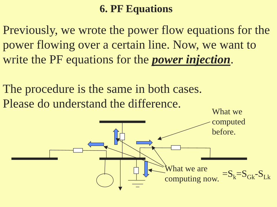
6. PF Equations
Previously, we wrote the power flow equations for the
power flowing over a certain line. Now, we want to
write the PF equations for the power injection.
The procedure is the same in both cases.
Please do understand the difference.What we
computed
before.
What we are
computing now.=Sk=SGk-SLk
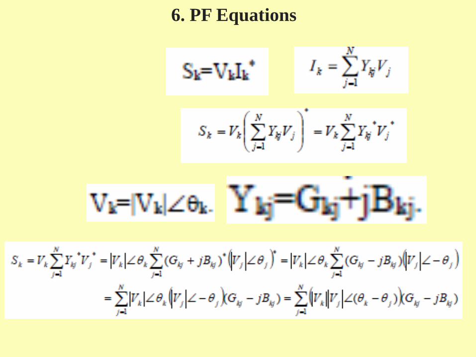
6. PF Equations

6. PF Equations
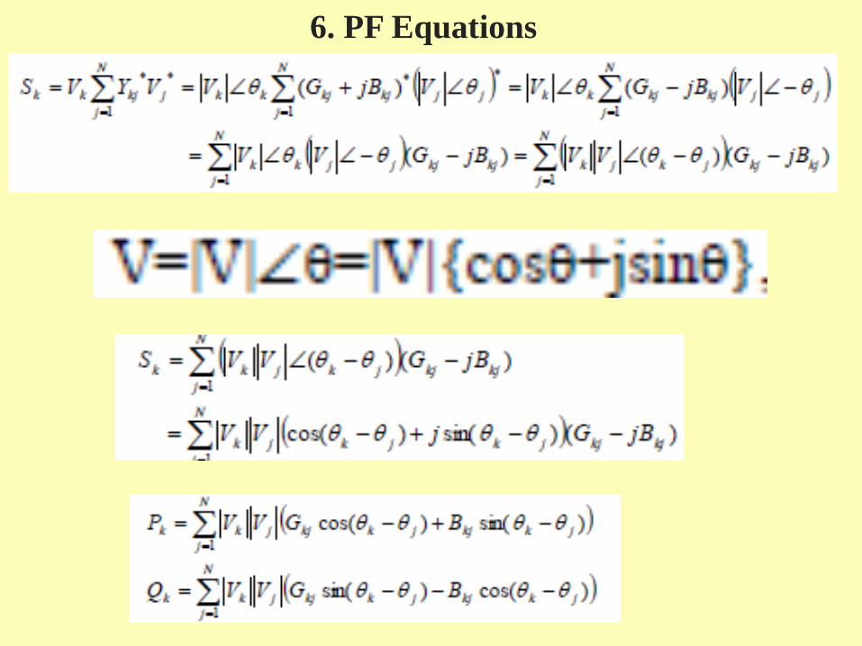
6. PF Equations