Embed Size (px)
Citation preview
1 | P a g e
NPTEL IIT Kharagpur Web Courses
Module 19 : Aerobic Secondary Treatment Of Wastewater Lecture 24 : Aerobic Secondary Treatment Of Wastewater
2 | P a g e
NPTEL IIT Kharagpur Web Courses
19.1 Activated Sludge Process Conventional biological treatment of wastewater under aerobic conditions includes activated
sludge process (ASP) and Trickling Filter. The ASP was developed in England in 1914. The
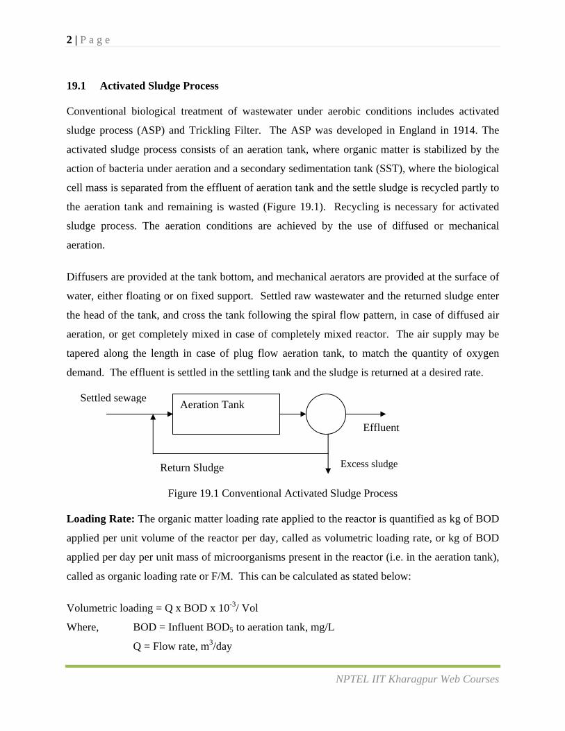
activated sludge process consists of an aeration tank, where organic matter is stabilized by the
action of bacteria under aeration and a secondary sedimentation tank (SST), where the biological
cell mass is separated from the effluent of aeration tank and the settle sludge is recycled partly to
the aeration tank and remaining is wasted (Figure 19.1). Recycling is necessary for activated
sludge process. The aeration conditions are achieved by the use of diffused or mechanical
aeration.
Diffusers are provided at the tank bottom, and mechanical aerators are provided at the surface of
water, either floating or on fixed support. Settled raw wastewater and the returned sludge enter
the head of the tank, and cross the tank following the spiral flow pattern, in case of diffused air
aeration, or get completely mixed in case of completely mixed reactor. The air supply may be
tapered along the length in case of plug flow aeration tank, to match the quantity of oxygen
demand. The effluent is settled in the settling tank and the sludge is returned at a desired rate.
Figure 19.1 Conventional Activated Sludge Process Loading Rate: The organic matter loading rate applied to the reactor is quantified as kg of BOD
applied per unit volume of the reactor per day, called as volumetric loading rate, or kg of BOD
applied per day per unit mass of microorganisms present in the reactor (i.e. in the aeration tank),
called as organic loading rate or F/M. This can be calculated as stated below:
Volumetric loading = Q x BOD x 10-3/ Vol
Where, BOD = Influent BOD5 to aeration tank, mg/L
Q = Flow rate, m3/day
SSTAeration Tank
Settled sewage
Return Sludge
Effluent
Excess sludge
3 | P a g e
NPTEL IIT Kharagpur Web Courses
Vol. = Volume of aeration Tank, m3
Organic Loading Rate, F/M = Q x BOD / (V x Xt)
Where, Xt = MLVSS concentration in the aeration tank, mg/L
The F/M ratio is the main factor controlling BOD removal. Lower F/M values will give higher
BOD removal. The F/M can be varied by varying MLVSS concentration in the aeration tank.
Solid Retention Time (SRT) or Mean Cell Residence Time (MCRT): The performance of the
ASP in terms of organic matter removal depends on the duration for which the microbial mass is
retained in the system. The retention of the sludge depends on the settling rate of the sludge in
the SST. If sludge settles well in the SST proper recirculation of the sludge in aeration tank is
possible, this will help in maintaining desired SRT in the system. Otherwise, if the sludge has
poor settling properties, it will not settle in the SST and recirculation of the sludge will be
difficult and this may reduce the SRT in the system. The SRT can be estimated as stated below:
SRT = kg of MLVSS in aeration Tank (kg of VSS wasted per day + kg of VSS lost in effluent per day)
Generally, the VSS lost in the effluent are neglected as this is very small amount as compared to
artificial wasting of sludge carried out from the sludge recycle line or from aeration tank.
Sludge Volume Index: The quantity of the return sludge is determined on volumetric basis. The
sludge volume index (SVI) is the volume of the sludge in mL for one gram of dry weight of
suspended solids (SS), measured after 30 minutes of settling. The SVI varies from 50 to 150
mL/ g of SS. Lower SVI indicates better settling of sludge.
Quantity of Return Sludge: Usually solid concentration of about 1500 to 3000 mg/L (MLVSS
80% of MLSS) is maintained for conventional ASP and 3000 to 6000 mg/L for completely
mixed ASP. Accordingly the quantity of return sludge is determined to maintain this
concentration. The sludge return ratio is usually 20 to 50%. The F/M ratio is kept as 0.2 to 0.4
for conventional ASP and 0.2 to 0.6 for completely mixed ASP.
4 | P a g e
NPTEL IIT Kharagpur Web Courses
Sludge Bulking: The sludge which does not settle well in sedimentation tank is called as bulking
sludge. It may be due to either (a) the growth of filamentous microorganisms which do not allow
desirable compaction; or (b) due to the production of non-filamentous highly hydrated biomass.
There are many reasons for sludge bulking. The presence of toxic substances in influent,
lowering of temperature, insufficient aeration, and shock loading can also cause sludge bulking.
Proper supply of air and proper design to maintain endogenous growth phase of metabolism will
not produce bulking of sludge. The sludge bulking can be controlled by restoring proper air
supply, eliminating shock loading to the reactor, or by increasing temperature of the wastewater
or by small hypochlorite dosing to the return sludge line to avoid the growth of filamentous
hygroscopic microorganisms.
Mixing Conditions: The aeration tank can be of plug flow type or completely mixed type. In the
plug flow tank, the F/M and oxygen demand will be highest at the inlet end of the aeration tank
and it will then progressively decrease. In the completely mix system, the F/M and oxygen
demand will be uniform throughout the tank.
Flow Scheme: Sewage addition may be done at a single point at the inlet end of the tank or it
may be at several points along the aeration tank. The sludge return is carried out from the
underflow of the settling tank to the aeration tank. The sludge wastage can be done from return
sludge line or from aeration tank itself. Sludge wasting from the aeration tank will have better
control over the process, however higher sludge waste volume need to be handled in this case
due to lower concentration as compared to when wasting is done from underflow of SST. The
compressed air may be applied uniformly along the whole length of the tank or it may be tapered
from the head of the aeration tank to its end.
19.1.1 Aeration in ASP
Aeration units can be classified as:
1) Diffused Air Units2) Mechanical Aeration Units3) Combined Mechanical and diffused air units.
5 | P a g e
NPTEL IIT Kharagpur Web Courses
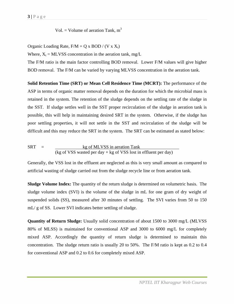
19.1.1.1 Diffused air aeration
In diffused air aeration, compressed air is blown through diffusers. The tanks of these units are
generally in the form of narrow rectangular channels. The air diffusers are provided at the
bottom of tank. The air before passing through diffusers must be passed through air filter to
remove dirt. The required pressure is maintained by means of air compressors.
Figure 19.2. Typical air diffusers arrangement
Types of air diffusers
a) Jet diffusers: These diffusers give direct stream of air in the form of jet downward and
strike against a small bowl kept just below the nozzle of the jet. The air flashes over the
surface of the bowl and escapes in the form of fine bubbles.
b) Porous diffusers: Manufactured in the form of tubes and plates from grains of crushed
quartz, aluminum oxide or carbon fused to form a porous structure. These are tile shaped
or tubular shape. 10 to 20 % area of the tank is covered with porous tiles. The supply of
air is done through pipeline laid in the floor of the tank and is controlled by the valves.
Depending upon the size of the air bubbles these can be classified as fine or medium
bubble diffused-air aeration device.
In common practice, porous dome type air diffusers of 10 to 20 cm diameter are used. These are
directly fixed on the top of C.I. main pipes laid at the bottom of the aeration tanks. These are
cheap in initial as well as maintenance cost.
Air Supply: Normally air is supplied under pressure of 0.55 to 0.7 kg/cm2. The quantity of air
supplied varies from 1.25 to 9.50 m3/m3 of sewage depending on the strength of the sewage to be
treated and degree of treatment desired. The oxygen transfer capacity of the aerators depends on
the size of air bubbles, for fine bubble oxygen transfer capabilities of aeration device is 0.7 to 1.4
6 | P a g e
NPTEL IIT Kharagpur Web Courses
kg O2/KW.h. For medium bubble it is 0.6 to 1.0 kg O2/KW.h, and for coarse bubble it is 0.3 to
0.9 kg O2/KW.h.
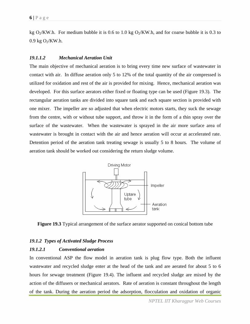
19.1.1.2 Mechanical Aeration Unit
The main objective of mechanical aeration is to bring every time new surface of wastewater in
contact with air. In diffuse aeration only 5 to 12% of the total quantity of the air compressed is
utilized for oxidation and rest of the air is provided for mixing. Hence, mechanical aeration was
developed. For this surface aerators either fixed or floating type can be used (Figure 19.3). The
rectangular aeration tanks are divided into square tank and each square section is provided with
one mixer. The impeller are so adjusted that when electric motors starts, they suck the sewage
from the centre, with or without tube support, and throw it in the form of a thin spray over the
surface of the wastewater. When the wastewater is sprayed in the air more surface area of
wastewater is brought in contact with the air and hence aeration will occur at accelerated rate.
Detention period of the aeration tank treating sewage is usually 5 to 8 hours. The volume of
aeration tank should be worked out considering the return sludge volume.
Figure 19.3 Typical arrangement of the surface aerator supported on conical bottom tube
19.1.2 Types of Activated Sludge Process
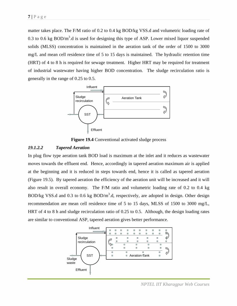
19.1.2.1 Conventional aeration
In conventional ASP the flow model in aeration tank is plug flow type. Both the influent
wastewater and recycled sludge enter at the head of the tank and are aerated for about 5 to 6
hours for sewage treatment (Figure 19.4). The influent and recycled sludge are mixed by the
action of the diffusers or mechanical aerators. Rate of aeration is constant throughout the length
of the tank. During the aeration period the adsorption, flocculation and oxidation of organic
7 | P a g e
NPTEL IIT Kharagpur Web Courses
matter takes place. The F/M ratio of 0.2 to 0.4 kg BOD/kg VSS.d and volumetric loading rate of
0.3 to 0.6 kg BOD/m3.d is used for designing this type of ASP. Lower mixed liquor suspended
solids (MLSS) concentration is maintained in the aeration tank of the order of 1500 to 3000
mg/L and mean cell residence time of 5 to 15 days is maintained. The hydraulic retention time
(HRT) of 4 to 8 h is required for sewage treatment. Higher HRT may be required for treatment
of industrial wastewater having higher BOD concentration. The sludge recirculation ratio is
generally in the range of 0.25 to 0.5.
Figure 19.4 Conventional activated sludge process
19.1.2.2 Tapered Aeration
In plug flow type aeration tank BOD load is maximum at the inlet and it reduces as wastewater
moves towards the effluent end. Hence, accordingly in tapered aeration maximum air is applied
at the beginning and it is reduced in steps towards end, hence it is called as tapered aeration
(Figure 19.5). By tapered aeration the efficiency of the aeration unit will be increased and it will
also result in overall economy. The F/M ratio and volumetric loading rate of 0.2 to 0.4 kg
BOD/kg VSS.d and 0.3 to 0.6 kg BOD/m3.d, respectively, are adopted in design. Other design
recommendation are mean cell residence time of 5 to 15 days, MLSS of 1500 to 3000 mg/L,
HRT of 4 to 8 h and sludge recirculation ratio of 0.25 to 0.5. Although, the design loading rates
are similar to conventional ASP, tapered aeration gives better performance.
Effluent
SST
Sludge recirculation
Influent
Aeration Tank
Effluent
SST
Sludge recirculation
Influent
Sludgewaste
Aeration Tank
8 | P a g e
NPTEL IIT Kharagpur Web Courses
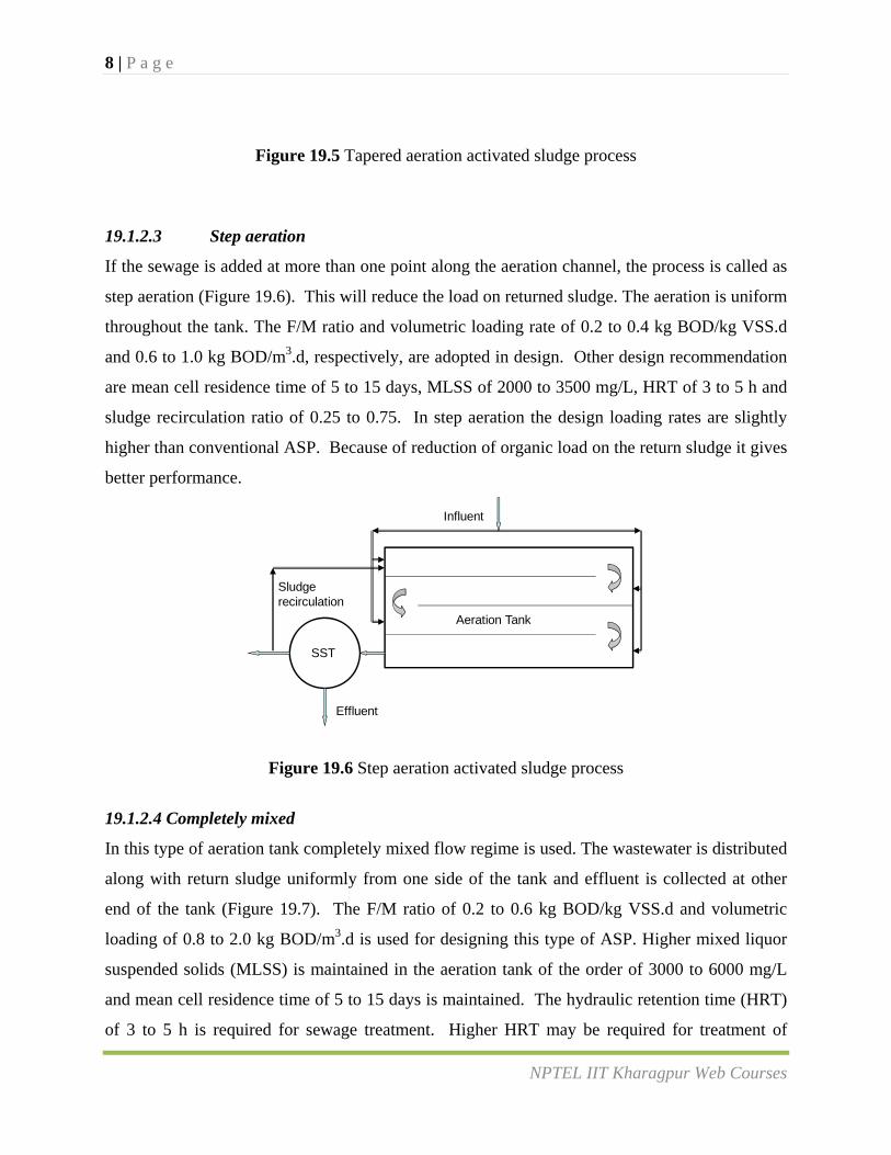
Figure 19.5 Tapered aeration activated sludge process
19.1.2.3 Step aeration
If the sewage is added at more than one point along the aeration channel, the process is called as
step aeration (Figure 19.6). This will reduce the load on returned sludge. The aeration is uniform
throughout the tank. The F/M ratio and volumetric loading rate of 0.2 to 0.4 kg BOD/kg VSS.d
and 0.6 to 1.0 kg BOD/m3.d, respectively, are adopted in design. Other design recommendation
are mean cell residence time of 5 to 15 days, MLSS of 2000 to 3500 mg/L, HRT of 3 to 5 h and
sludge recirculation ratio of 0.25 to 0.75. In step aeration the design loading rates are slightly
higher than conventional ASP. Because of reduction of organic load on the return sludge it gives
better performance.
Figure 19.6 Step aeration activated sludge process
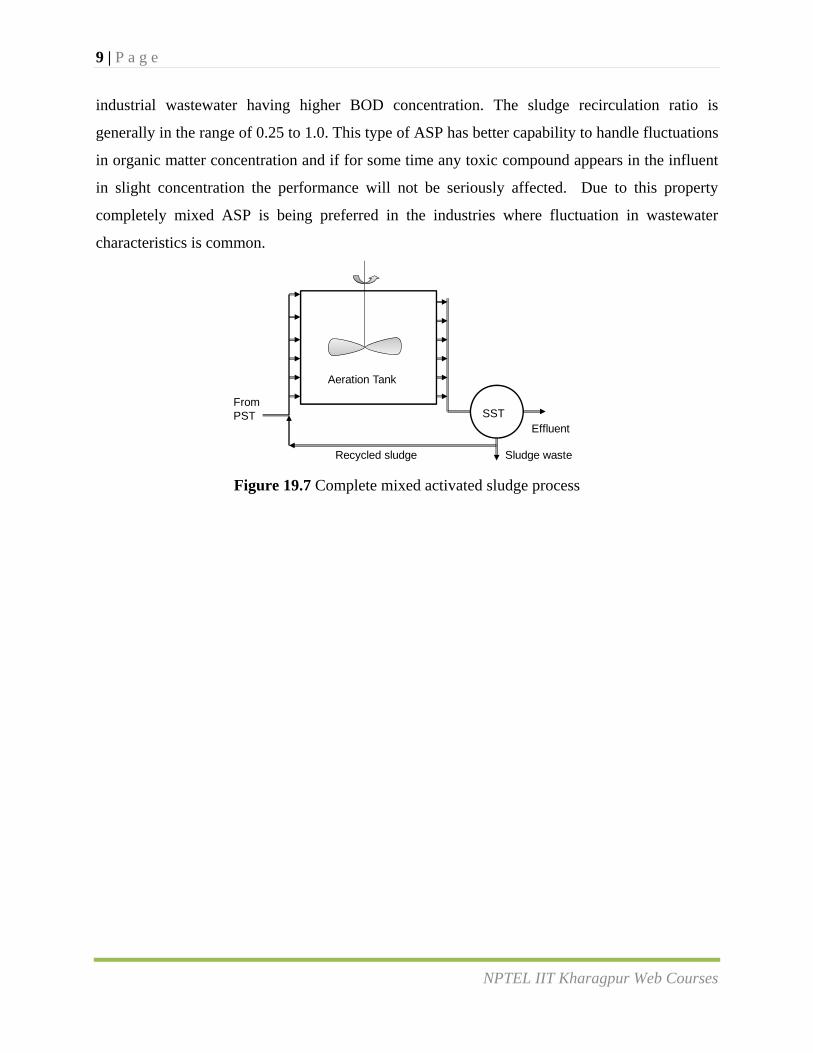
19.1.2.4 Completely mixed
In this type of aeration tank completely mixed flow regime is used. The wastewater is distributed
along with return sludge uniformly from one side of the tank and effluent is collected at other
end of the tank (Figure 19.7). The F/M ratio of 0.2 to 0.6 kg BOD/kg VSS.d and volumetric
loading of 0.8 to 2.0 kg BOD/m3.d is used for designing this type of ASP. Higher mixed liquor
suspended solids (MLSS) is maintained in the aeration tank of the order of 3000 to 6000 mg/L
and mean cell residence time of 5 to 15 days is maintained. The hydraulic retention time (HRT)
of 3 to 5 h is required for sewage treatment. Higher HRT may be required for treatment of
Effluent
SST
Sludge recirculation
Influent
Aeration Tank
9 | P a g e
NPTEL IIT Kharagpur Web Courses
industrial wastewater having higher BOD concentration. The sludge recirculation ratio is
generally in the range of 0.25 to 1.0. This type of ASP has better capability to handle fluctuations
in organic matter concentration and if for some time any toxic compound appears in the influent
in slight concentration the performance will not be seriously affected. Due to this property
completely mixed ASP is being preferred in the industries where fluctuation in wastewater
characteristics is common.
Figure 19.7 Complete mixed activated sludge process
From PST
Aeration Tank
SSTEffluent
Sludge wasteRecycled sludge