Embed Size (px)
Citation preview
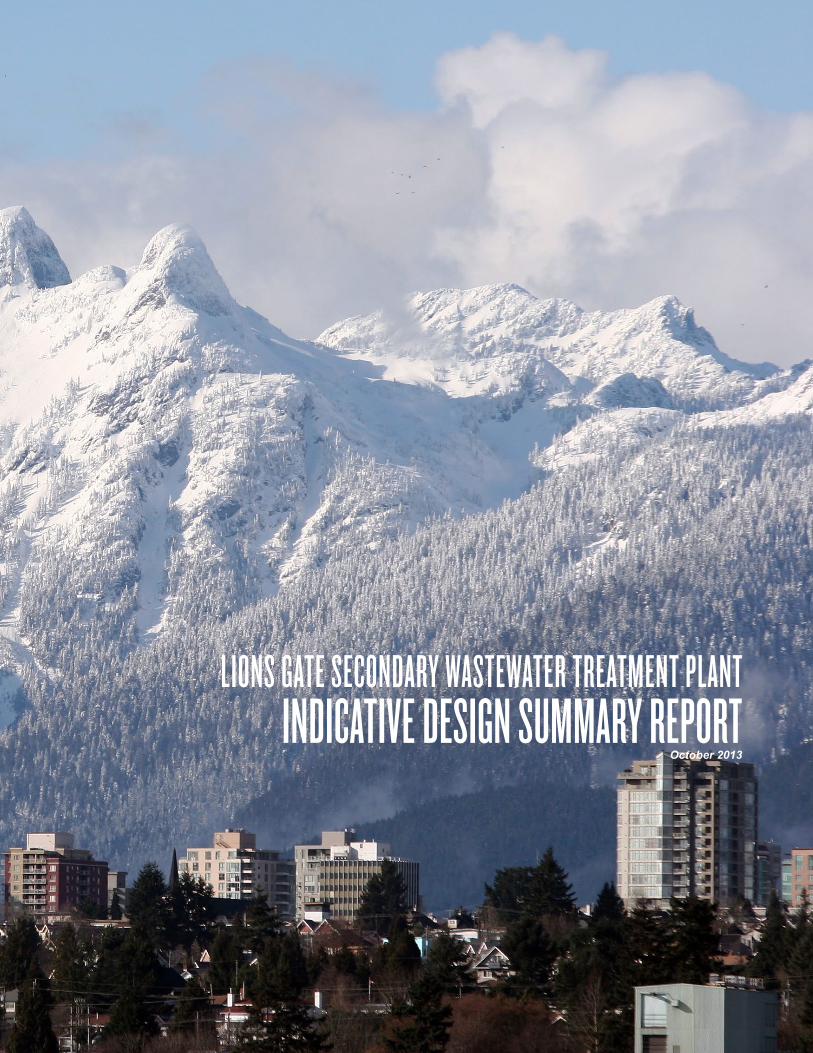
LIONS GATE SECONDARY WASTEWATER TREATMENT PLANTINDICATIVE DESIGN SUMMARY REPORT
October 2013
UC-48
LIONS GATE SECONDARY WASTEWATER TREATMENT PLANTINDICATIVE DESIGN SUMMARY REPORT
1 EXECUTIVE SUMMARY 2 PROJECT BACKGROUND3 PROJECT OBJECTIVES4 KEY DESIGN CRITERIA5 SITE CHARACTERIZATION6 INDICATIVE DESIGN7 PROJECT IMPLEMENTATION SCHEDULE
The Integrative Design Process model dissolves traditional discipline oriented silos, thereby allowing the project team to discover opportunities that emerge from the design process which would otherwise be unrealized. The integrative process provides a robust framework for the team to work across disciplines to develop concepts consistent with Metro Vancouver’s four key objectives, simultaneously fostering exploration of the interdependencies between key project objectives. Involvement of all disciplines throughout the design process resulted in an indicative design that is more responsive to a range of criteria.
UC-50
5
1 EXECUTIVE SUMMARY
Indicative Design Summary Report
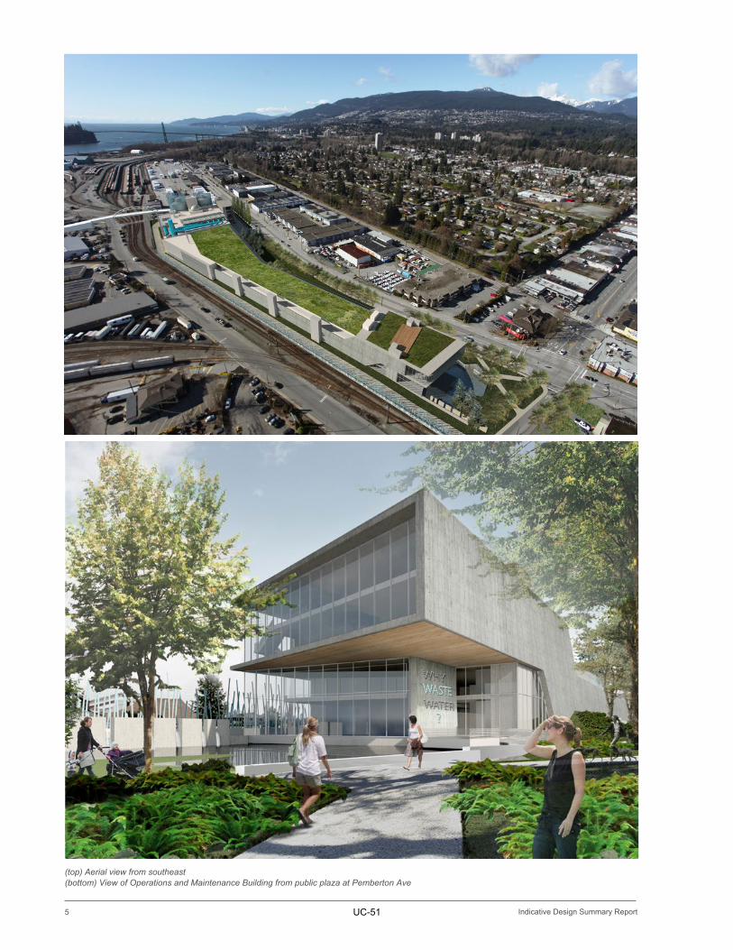
(top) Aerial view from southeast(bottom) View of Operations and Maintenance Building from public plaza at Pemberton Ave
UC-51
6
EXECUTIVE SUMMARY 1
Indicative Design Summary Report
1 . E X E C U T I V E S U M M A R YThe Lions Gate Secondary Wastewater Treatment Plant presents an opportunity to simultaneously provide a needed upgrade to an essential service, protect the local environment and contribute to development on the North Shore. Located on former BC Rail lands, the intent of this Indicative Design is to define the scope of the work required for the delivery of a twenty first century wastewater treatment plant. The Lions Gate Secondary Wastewater Treatment Plant will occupy much of its 3.5 hectare site, employing best practices for wastewater treatment and providing maximum flexibility for future treatment technology upgrades. The Indicative Design included in this report was developed specifically to fulfill Metro Vancouver’s four goals for the project, including:
1. The provision of robust secondary wastewater treatment. 2. The development and demonstration of a project that is socially, ecologically and economically sustainable. 3. The implementation of integrated resource recovery strategies. 4. The creation of a facility integrated into the community. The project team has worked together in a highly collaborative way with a large number of stakeholder groups including businesses, residents, technical experts, local government and First Nations in order to integrate these objectives with the project design. The outcome is a facility that is resilient and future proof; belongs to the place; is secure but visually open to the community; has the potential to be a net producer of energy; and that can be used to teach future generations about sustainable building, wastewater treatment and environmental stewardship. This Indicative Design Summary Report provides a brief overview of the defined project. It describes the recommended treatment technology, architectural character, and community integration opportunities present in the Lions Gate Secondary Wastewater Treatment Plant.
In early 2014, Metro Vancouver will assess its construction procurement options and funding structures. Following the Board decision on procurement and funding, the design and construction phase is expected to commence with a project completion date of December 31, 2020.
UC-52
7
2 PROJECT BACKGROUND
Indicative Design Summary Report
1 . P R O J E C T N E E D
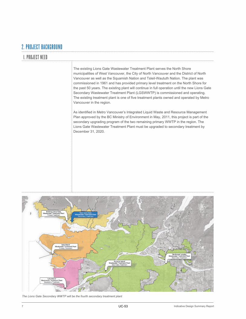
The existing Lions Gate Wastewater Treatment Plant serves the North Shore municipalities of West Vancouver, the City of North Vancouver and the District of North Vancouver as well as the Squamish Nation and Tsleil-Waututh Nation. The plant was commissioned in 1961 and has provided primary level treatment on the North Shore for the past 50 years. The existing plant will continue in full operation until the new Lions Gate Secondary Wastewater Treatment Plant (LGSWWTP) is commissioned and operating. The existing treatment plant is one of five treatment plants owned and operated by Metro Vancouver in the region.
As identified in Metro Vancouver’s Integrated Liquid Waste and Resource Management Plan approved by the BC Ministry of Environment in May, 2011, this project is part of the secondary upgrading program of the two remaining primary WWTP in the region. The Lions Gate Wastewater Treatment Plant must be upgraded to secondary treatment by December 31, 2020.
2 . P R O J E C T B A C K G R O U N D
The Lions Gate Secondary WWTP will be the fourth secondary treatment plant
UC-53
8
PROJECT BACKGROUND 2
Indicative Design Summary Report
2 . D E V E L O P M E N T O F A LT E R N AT I V E S
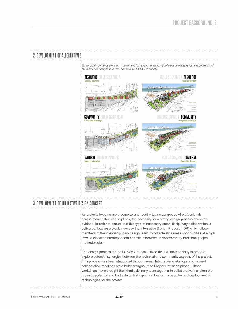
Three build scenarios were considered and focused on enhancing different characteristics and potentials of the indicative design: resource, community, and sustainability.
3 . D E V E L O P M E N T O F I N D I C AT I V E D E S I G N C O N C E P T
As projects become more complex and require teams composed of professionals across many different disciplines, the necessity for a strong design process becomes evident. In order to ensure that this type of necessary cross disciplinary collaboration is delivered, leading projects now use the Integrative Design Process (IDP) which allows members of the interdisciplinary design team to collectively assess opportunities at a high level to discover interdependent benefits otherwise undiscovered by traditional project methodologies.
The design process for the LGSWWTP has utilized the IDP methodology in order to explore potential synergies between the technical and community aspects of the project. This process has been elaborated through seven Integrative workshops and several collaboration meetings were held throughout the Project Definition phase. These workshops have brought the interdisciplinary team together to collaboratively explore the project’s potential and had substantial impact on the form, character and deployment of technologies for the project.
UC-54
9
3 PROJECT OBJECTIVES
Indicative Design Summary Report
1 . S E C O N D A R Y W A S T E W AT E R T R E AT M E N T
IDP:The Integrative Design Process allows a team with a wide range of knowledge and expertise to come together to address the four project objectives as an, interrelated whole rather than as individual components considered in isolation.
The key objective for wastewater treatment will be to meet the requirements for secondary level treatment as defined in the new Government of Canada Wastewater System Effluent Regulations and specified by the BC Ministry of Environment in a new Operational Certificate in accordance with the Integrated Liquid Waste and Resource management Plan
2 . S U S TA I N A B I L I T Y
DISTRICT ENERGY SITE STORMWATER MANAGEMENTDAYLIGHTINGEFFLUENT-SOURCE HEATPASSIVE VENTILATION
The project will optimize the generation and capture of valuable materials to be repurposed for fuel, water, fertilizer and heat, helping Metro Vancouver in reducing its energy costs, carbon footprint, potable water use and environmental impact. Metro Vancouver has an opportunity through this project to demonstrate its commitment to sustainability, to provide leadership, and to build a model facility, while fulfilling its mandate of providing of a core service. In working to achieve this goal, business cases were developed in line with the following objectives:
• Minimize energy use and maximize energy recovery from plant operations • Minimize the generation of waste and maximize reuse and recycling of waste
during construction, operation, and deconstruction/decommissioning. • Minimize the region’s contribution to climate change. • Minimize off-site impacts of stormwater and effluent discharge. • Provide a facility that is an asset to the community. • Develop and apply decision-making processes that are transparent, inclusive,
and respectful of the interests of all affected parties. • Demonstrate Metro Vancouver’s values and commitment to sustainability
through the creation of a model facility for others to emulate. • Provide a facility that is financially sustainable and provides value for money for
Metro Vancouver rate payers.
3 . P R O J E C T O B J E C T I V E SGrounding all IDP exchanges have been four project goals established prior to the project commencement by Metro Vancouver. These are: Robust Secondary Wastewater Treatment; the Use and Demonstration of Sustainable Design Principles; the implementation of Integrated Resource Recovery Strategies, and strong Community Integration.
UC-55
10
PROJECT OBJECTIVES 3
Indicative Design Summary Report
3 . I N T E G R AT E D R E S O U R C E R E C O V E R Y
The wastewater treatment process has the potential to generate a number of valuable materials, including fuel (digester gas or biogas), water (treated effluent), fertilizer or fuel (biosolids), and heat.
• Maximize generation and capture of digester gas (biogas) • Maximize recovery of energy through co-management with solid waste organics • Maximize recovery of heat from effluent • Harness cooling potential • Maximize use of reclaimed water • Generate high quality biosolids for beneficial use • Maximize recovery of nutrients from wastewater
4 . C O M M U N I T Y I N T E G R AT I O N
The site is between active commercial, industrial, and residential zones, and thus its character and urban integration are crucial. By exploring community partnerships, mutual interests, education opportunities and public engagement positions, Metro Vancouver aims to provide a positive influence to the urban character rather than only minimizing the community impact. Working with residents, businesses and interested parties allowed for the exploration of potential community assets.
UC-56
11
3 PROJECT OBJECTIVES
Indicative Design Summary Report
1 . D E S I G N H O R I Z O N
The design horizon for the LGSWWTP site extends to 2101 and major infrastructure, including tanks such as the digesters and primary and secondary treatment tanks have been sized to accommodate projected population growth on the North Shore.
2 . S E R V I C E P O P U L AT I O N A N D W A S T E W AT E R F L O W S A N D L O A D S
UTILIZING THE TREATMENT TANKS WITH
EFFICIENCY IMPROVEMENTS WILL ALLOW THE
PLANT TO ACCOMMODATE THE PROJECTED
POPULATION GROWTH BETWEEN 2051 AND 2101
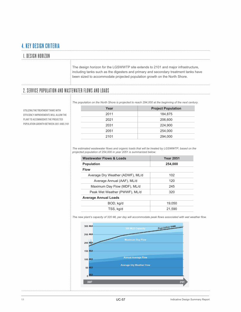
The population on the North Shore is projected to reach 294,000 at the beginning of the next century.
The estimated wastewater flows and organic loads that will be treated by LGSWWTP, based on the projected population of 254,000 in year 2051 is summarized below:
The new plant’s capacity of 320 ML per day will accommodate peak flows associated with wet weather flow.
4 . K E Y D E S I G N C R I T E R I A
Year Project Population2011 184,8752021 206,6002031 224,9002051 254,0002101 294,000
Wastewater Flows & Loads Year 2051Population 254,000Flow
Average Dry Weather (ADWF), ML/d 102Average Annual (AAF), ML/d 120
Maximum Day Flow (MDF), ML/d 245Peak Wet Weather (PWWF), ML/d 320
Average Annual LoadsBOD, kg/d 19,050TSS, kg/d 21,590
MLD
MLD
MLD
MLD
MLD
MLD
MLD
X1000
UC-57
12
KEY DESIGN CRITERIA 4
Indicative Design Summary Report
3 . T R E AT E D E F F L U E N T R E Q U I R E M E N T S
There are two primary regulations that govern the quality of treated effluent discharged from LGSWWTP to the Burrard Inlet:
• Environment Canada (2012). Fisheries Act, Wastewater Systems Effluent Regulations SOR/2012-139.
• BC Ministry of Environment (2012). Environmental Management Act, Metro Vancouver’s Integrated Liquid Waste and Resource Management Plan
Metro Vancouver’s existing Operational Certificate for the Lions Gate Wastewater Treatment Plant will be amended to reflect the requirements of the regulations.
The treated effluent from LGSWWTP must be equivalent to or better than• 5-day Carbonaceous Biochemical Oxygen Demand: Monthly average < 25 mg/L• Total Suspended Solids: Monthly average < 25 mg/L• Unionized Ammonia: Maximum < 1.25 mg/L
The requirement for disinfection is seasonal between May 1 and September 30. Also, treated effluent from LGSWWTP must not be acutely toxic to aquatic organisms.
4 . C O M M U N I T Y I N T E G R AT I O N C R I T E R I A
Throughout the project definition phase, Metro Vancouver has consulted with a wide variety of stakeholders in order to determine the most effective community integration possibilities. These included providing:
1. Odour mitigation to address community concerns 2. Spaces to support outreach and educational opportunities3. Public amenities along 1st St., the foot of Pemberton Avenue and the treatment
plant roof
UC-58
13
5 SITE CHARACTERIZATION
Indicative Design Summary Report
1 . P R O P O S E D S I T E
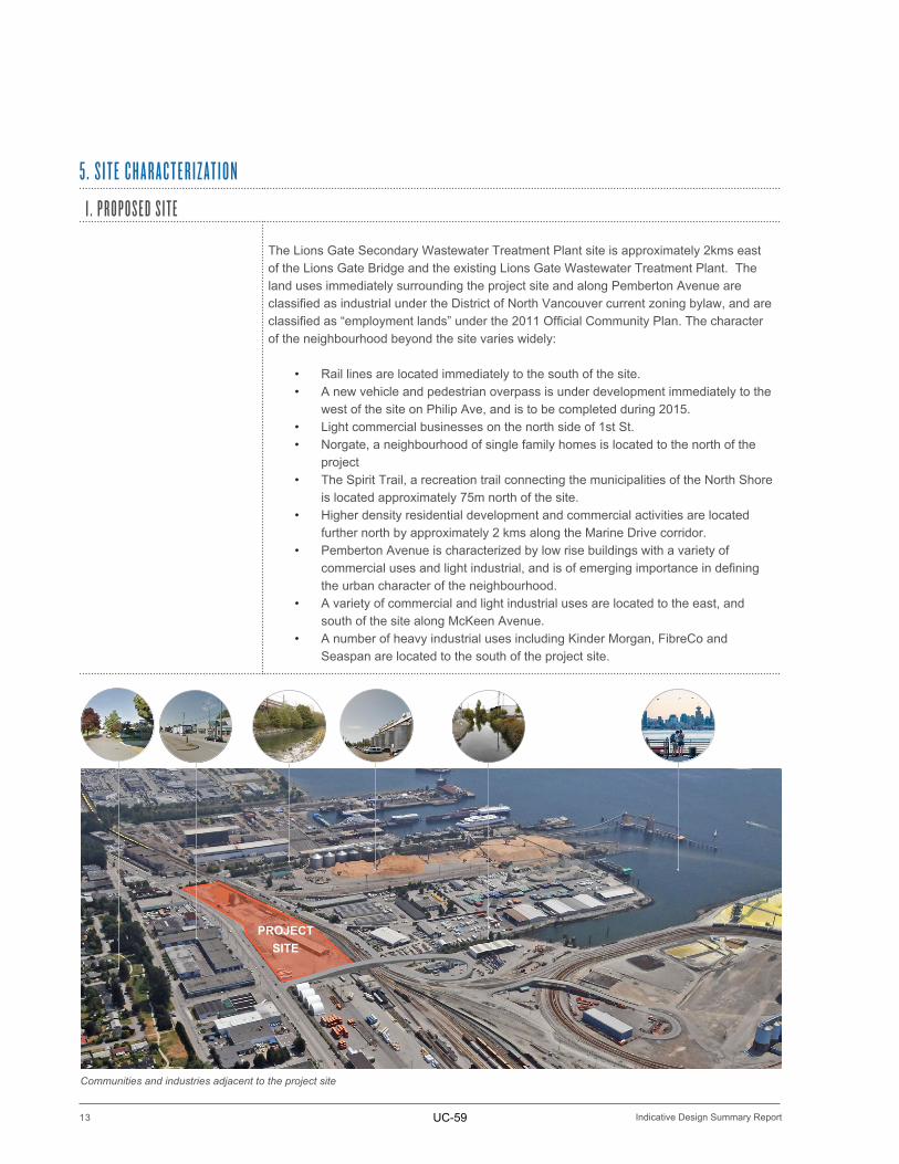
The Lions Gate Secondary Wastewater Treatment Plant site is approximately 2kms east of the Lions Gate Bridge and the existing Lions Gate Wastewater Treatment Plant. The land uses immediately surrounding the project site and along Pemberton Avenue are classified as industrial under the District of North Vancouver current zoning bylaw, and are classified as “employment lands” under the 2011 Official Community Plan. The character of the neighbourhood beyond the site varies widely:
• Rail lines are located immediately to the south of the site.• A new vehicle and pedestrian overpass is under development immediately to the
west of the site on Philip Ave, and is to be completed during 2015.• Light commercial businesses on the north side of 1st St. • Norgate, a neighbourhood of single family homes is located to the north of the
project• The Spirit Trail, a recreation trail connecting the municipalities of the North Shore
is located approximately 75m north of the site.• Higher density residential development and commercial activities are located
further north by approximately 2 kms along the Marine Drive corridor. • Pemberton Avenue is characterized by low rise buildings with a variety of
commercial uses and light industrial, and is of emerging importance in defining the urban character of the neighbourhood.
• A variety of commercial and light industrial uses are located to the east, and south of the site along McKeen Avenue.
• A number of heavy industrial uses including Kinder Morgan, FibreCo and Seaspan are located to the south of the project site.
5 . S I T E C H A R A C T E R I Z AT I O N
PROJECT SITE
Communities and industries adjacent to the project site
UC-59
14
SITE CHARACTERIZATION 5
Indicative Design Summary Report
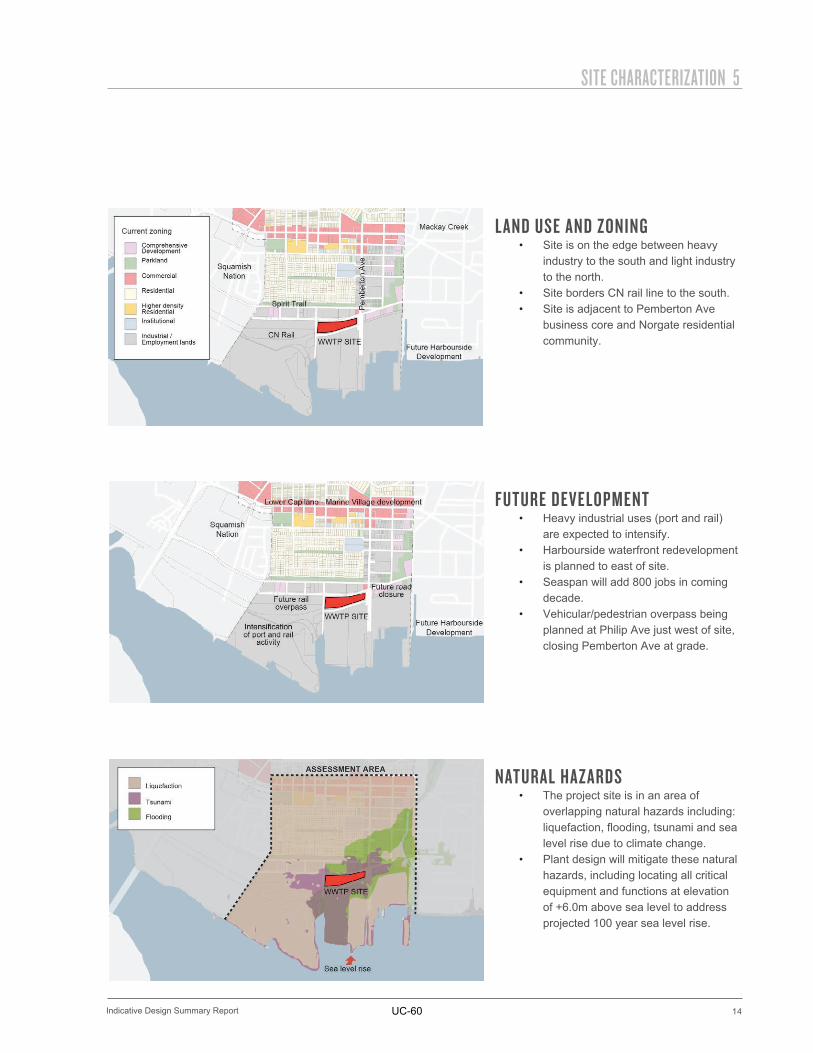
LAND USE AND ZONING• Site is on the edge between heavy
industry to the south and light industry to the north.
• Site borders CN rail line to the south.• Site is adjacent to Pemberton Ave
business core and Norgate residential community.
FUTURE DEVELOPMENT• Heavy industrial uses (port and rail)
are expected to intensify.• Harbourside waterfront redevelopment
is planned to east of site.• Seaspan will add 800 jobs in coming
decade.• Vehicular/pedestrian overpass being
planned at Philip Ave just west of site, closing Pemberton Ave at grade.
NATURAL HAZARDS• The project site is in an area of
overlapping natural hazards including: liquefaction, flooding, tsunami and sea level rise due to climate change.
• Plant design will mitigate these natural hazards, including locating all critical equipment and functions at elevation of +6.0m above sea level to address projected 100 year sea level rise.
UC-60
15
5 SITE CHARACTERIZATION
Indicative Design Summary Report
2 . G E O T E C H N I C A L C O N S I D E R AT I O N S
SOIL LIQUEFACTION DESCRIBES A PHENOMENON WHEREBY A SATURATED OR PARTIALLY SATURATED SOIL SUBSTANTIALLY LOSES STRENGTH AND STIFFNESS IN RESPONSE TO AN APPLIED STRESS, USUALLY EARTHQUAKE SHAKING OR OTHER SUDDEN CHANGE IN STRESS CONDITION, CAUSING IT TO BEHAVE LIKE A LIQUID
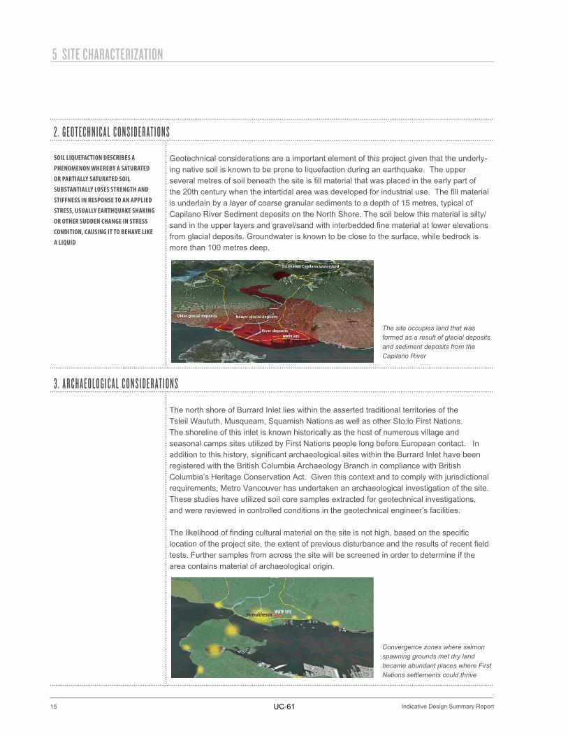
Geotechnical considerations are a important element of this project given that the underly-ing native soil is known to be prone to liquefaction during an earthquake. The upper several metres of soil beneath the site is fill material that was placed in the early part of the 20th century when the intertidal area was developed for industrial use. The fill material is underlain by a layer of coarse granular sediments to a depth of 15 metres, typical of Capilano River Sediment deposits on the North Shore. The soil below this material is silty/sand in the upper layers and gravel/sand with interbedded fine material at lower elevations from glacial deposits. Groundwater is known to be close to the surface, while bedrock is more than 100 metres deep.
3 . A R C H A E O L O G I C A L C O N S I D E R AT I O N S
The north shore of Burrard Inlet lies within the asserted traditional territories of the Tsleil Waututh, Musqueam, Squamish Nations as well as other Sto:lo First Nations. The shoreline of this inlet is known historically as the host of numerous village and seasonal camps sites utilized by First Nations people long before European contact. In addition to this history, significant archaeological sites within the Burrard Inlet have been registered with the British Columbia Archaeology Branch in compliance with British Columbia’s Heritage Conservation Act. Given this context and to comply with jurisdictional requirements, Metro Vancouver has undertaken an archaeological investigation of the site. These studies have utilized soil core samples extracted for geotechnical investigations, and were reviewed in controlled conditions in the geotechnical engineer’s facilities.
The likelihood of finding cultural material on the site is not high, based on the specific location of the project site, the extent of previous disturbance and the results of recent field tests. Further samples from across the site will be screened in order to determine if the area contains material of archaeological origin.
The site occupies land that was formed as a result of glacial deposits and sediment deposits from the Capilano River
Convergence zones where salmon spawning grounds met dry land became abundant places where First Nations settlements could thrive
UC-61
16
SITE CHARACTERIZATION 5
Indicative Design Summary Report
4 . E C O L O G I C A L C O N T E X T A N D S I T E C O N D I T I O N S
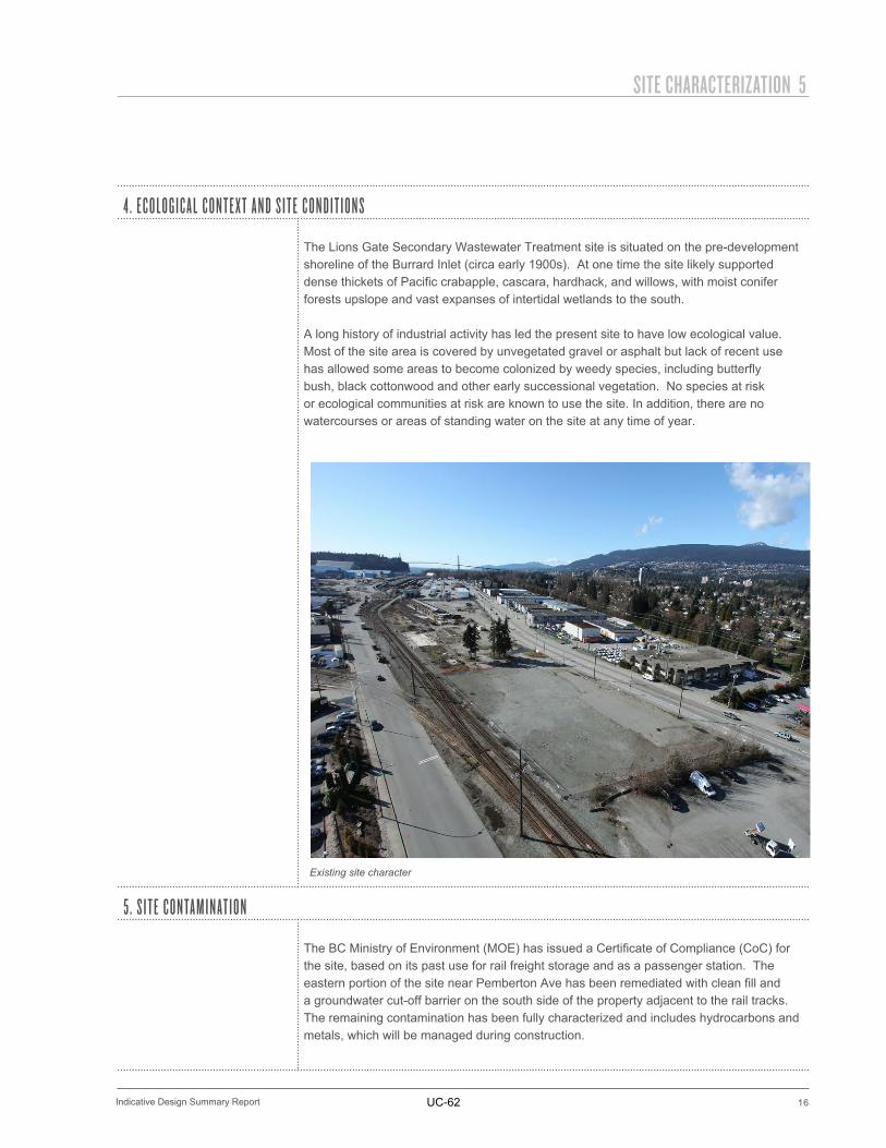
The Lions Gate Secondary Wastewater Treatment site is situated on the pre-development shoreline of the Burrard Inlet (circa early 1900s). At one time the site likely supported dense thickets of Pacific crabapple, cascara, hardhack, and willows, with moist conifer forests upslope and vast expanses of intertidal wetlands to the south.
A long history of industrial activity has led the present site to have low ecological value. Most of the site area is covered by unvegetated gravel or asphalt but lack of recent use has allowed some areas to become colonized by weedy species, including butterfly bush, black cottonwood and other early successional vegetation. No species at risk or ecological communities at risk are known to use the site. In addition, there are no watercourses or areas of standing water on the site at any time of year.
5 . S I T E C O N TA M I N AT I O N
The BC Ministry of Environment (MOE) has issued a Certificate of Compliance (CoC) for the site, based on its past use for rail freight storage and as a passenger station. The eastern portion of the site near Pemberton Ave has been remediated with clean fill and a groundwater cut-off barrier on the south side of the property adjacent to the rail tracks. The remaining contamination has been fully characterized and includes hydrocarbons and metals, which will be managed during construction.
Existing site character
UC-62
6 . L I O N S G AT E S E C O N D A R Y W A S T E W AT E R T R E AT M E N T P L A N T I N D I C AT I V E D E S I G N
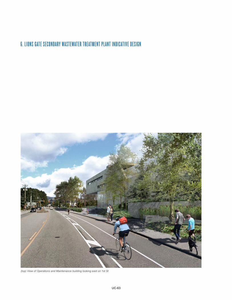
(top) View of Operations and Maintenance building looking east on 1st St
UC-63
18
INDICATIVE DESIGN 6
Indicative Design Summary Report
The configuration of Lions Gate Secondary Wastewater Treatment Plant is a result of collaborative design efforts between design team disciplines to develop a compact, contextual addition to the diverse zoning in the neighbourhood. Given the visibility of the site to arterial traffic, the Spirit Trail and the cycle route bounding its northern perimeter great care has been taken with the project massing. A translucent “gallery” reduces the apparent height of the facility from the street level while extensive planting and site grading rise up from 1st St. to modulate the scale of the plant.
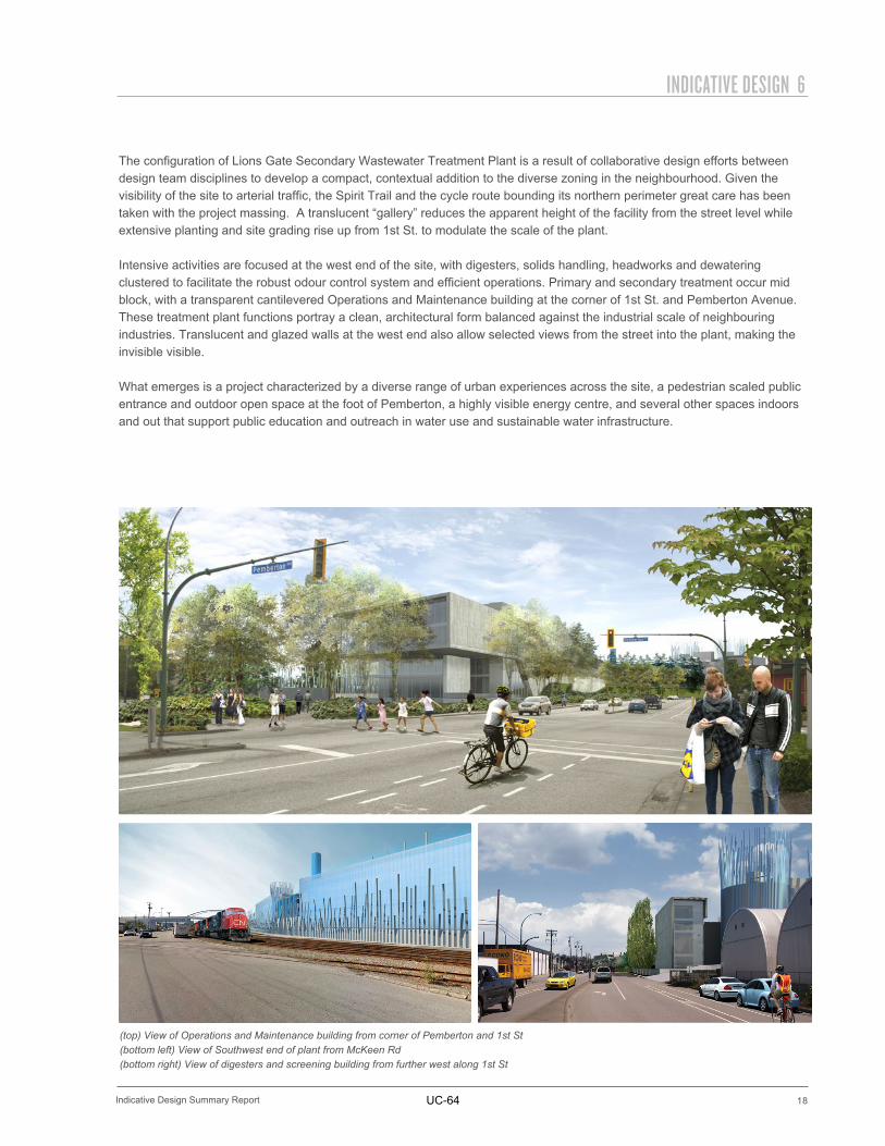
Intensive activities are focused at the west end of the site, with digesters, solids handling, headworks and dewatering clustered to facilitate the robust odour control system and efficient operations. Primary and secondary treatment occur mid block, with a transparent cantilevered Operations and Maintenance building at the corner of 1st St. and Pemberton Avenue. These treatment plant functions portray a clean, architectural form balanced against the industrial scale of neighbouring industries. Translucent and glazed walls at the west end also allow selected views from the street into the plant, making the invisible visible.
What emerges is a project characterized by a diverse range of urban experiences across the site, a pedestrian scaled public entrance and outdoor open space at the foot of Pemberton, a highly visible energy centre, and several other spaces indoors and out that support public education and outreach in water use and sustainable water infrastructure.
(top) View of Operations and Maintenance building from corner of Pemberton and 1st St(bottom left) View of Southwest end of plant from McKeen Rd(bottom right) View of digesters and screening building from further west along 1st St
UC-64
19
6 INDICATIVE DESIGN
Indicative Design Summary Report
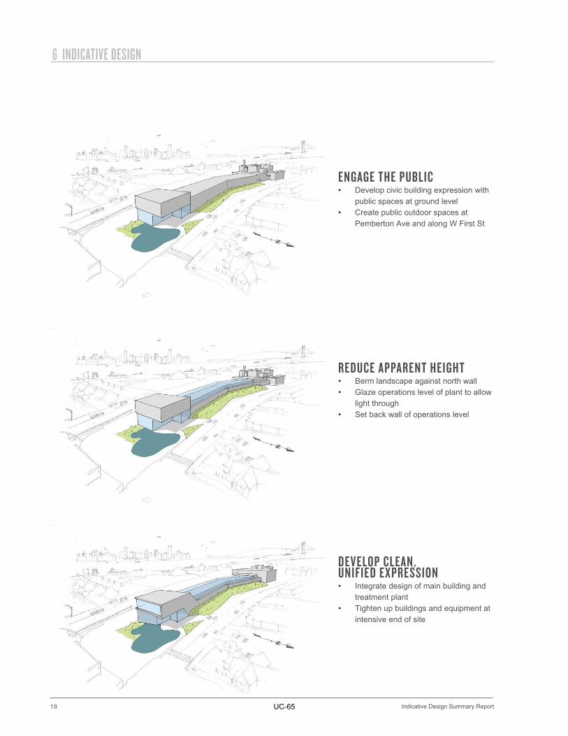
ENGAGE THE PUBLIC• Develop civic building expression with
public spaces at ground level• Create public outdoor spaces at
Pemberton Ave and along W First St
REDUCE APPARENT HEIGHT• Berm landscape against north wall• Glaze operations level of plant to allow
light through• Set back wall of operations level
DEVELOP CLEAN, UNIFIED EXPRESSION• Integrate design of main building and
treatment plant• Tighten up buildings and equipment at
intensive end of site
UC-65
20
INDICATIVE DESIGN 6
Indicative Design Summary Report
1 . O P E R AT I O N S A N D M A I N T E N A N C E B U I L D I N G
LEVEL 4
OPERATIONS
LEVEL 3
MAINTENANCE
LEVEL 2
LABORATORY
GROUND LEVEL 1
DISTRICT ENERGY
PLANT LOBBY
PUBLIC LOBBY AND MEETING
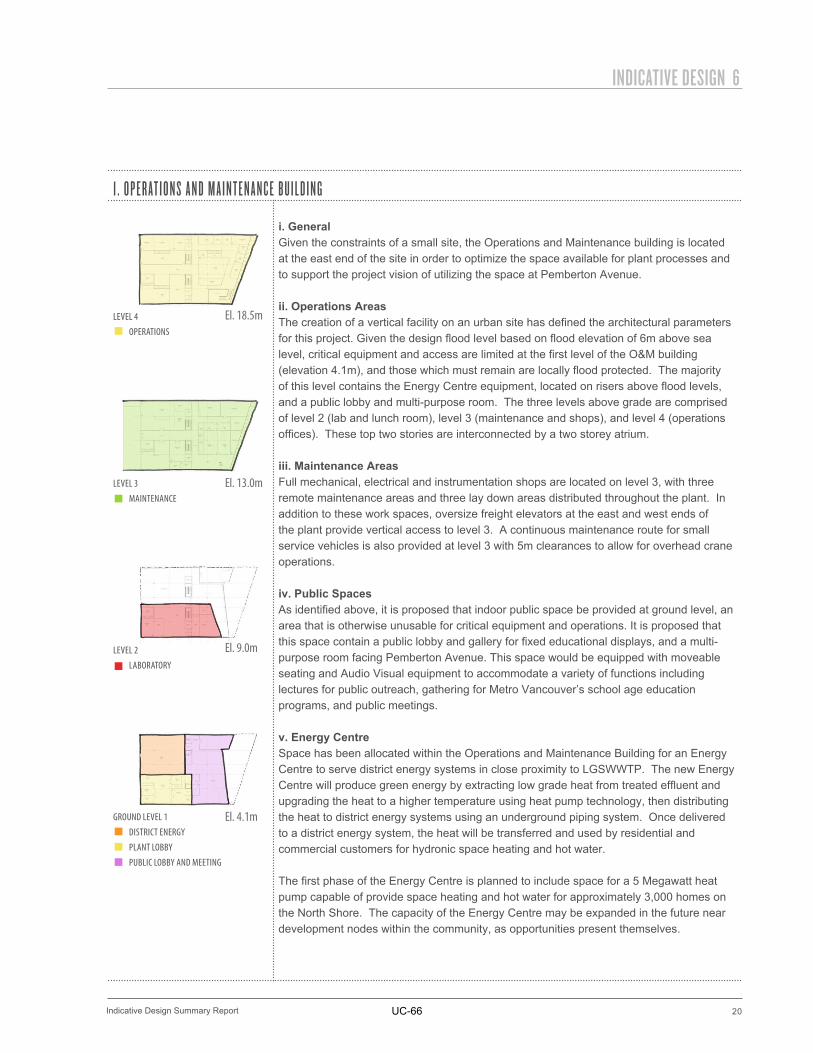
i. GeneralGiven the constraints of a small site, the Operations and Maintenance building is located at the east end of the site in order to optimize the space available for plant processes and to support the project vision of utilizing the space at Pemberton Avenue.
ii. Operations AreasThe creation of a vertical facility on an urban site has defined the architectural parameters for this project. Given the design flood level based on flood elevation of 6m above sea level, critical equipment and access are limited at the first level of the O&M building (elevation 4.1m), and those which must remain are locally flood protected. The majority of this level contains the Energy Centre equipment, located on risers above flood levels, and a public lobby and multi-purpose room. The three levels above grade are comprised of level 2 (lab and lunch room), level 3 (maintenance and shops), and level 4 (operations offices). These top two stories are interconnected by a two storey atrium.
iii. Maintenance AreasFull mechanical, electrical and instrumentation shops are located on level 3, with three remote maintenance areas and three lay down areas distributed throughout the plant. In addition to these work spaces, oversize freight elevators at the east and west ends of the plant provide vertical access to level 3. A continuous maintenance route for small service vehicles is also provided at level 3 with 5m clearances to allow for overhead crane operations.
iv. Public SpacesAs identified above, it is proposed that indoor public space be provided at ground level, an area that is otherwise unusable for critical equipment and operations. It is proposed that this space contain a public lobby and gallery for fixed educational displays, and a multi-purpose room facing Pemberton Avenue. This space would be equipped with moveable seating and Audio Visual equipment to accommodate a variety of functions including lectures for public outreach, gathering for Metro Vancouver’s school age education programs, and public meetings.
v. Energy CentreSpace has been allocated within the Operations and Maintenance Building for an Energy Centre to serve district energy systems in close proximity to LGSWWTP. The new Energy Centre will produce green energy by extracting low grade heat from treated effluent and upgrading the heat to a higher temperature using heat pump technology, then distributing the heat to district energy systems using an underground piping system. Once delivered to a district energy system, the heat will be transferred and used by residential and commercial customers for hydronic space heating and hot water.
The first phase of the Energy Centre is planned to include space for a 5 Megawatt heat pump capable of provide space heating and hot water for approximately 3,000 homes on the North Shore. The capacity of the Energy Centre may be expanded in the future near development nodes within the community, as opportunities present themselves.
El. 18.5m
El. 13.0m
El. 9.0m
El. 4.1m
UC-66
21
6 INDICATIVE DESIGN
Indicative Design Summary Report
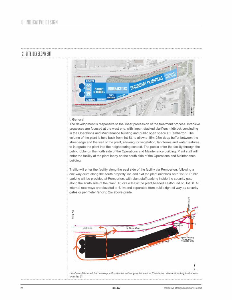
2 . S I T E D E V E L O P M E N T
i. GeneralThe development is responsive to the linear procession of the treatment process. Intensive processes are focused at the west end, with linear, stacked clarifiers midblock concluding in the Operations and Maintenance building and public open space at Pemberton. The volume of the plant is held back from 1st St. to allow a 15m-25m deep buffer between the street edge and the wall of the plant, allowing for vegetation, landforms and water features to integrate the plant into the neighbouring context. The public enter the facility through the public lobby on the north side of the Operations and Maintenance building. Plant staff will enter the facility at the plant lobby on the south side of the Operations and Maintenance building.
Traffic will enter the facility along the east side of the facility via Pemberton, following a one way drive along the south property line and exit the plant midblock onto 1st St. Public parking will be provided at Pemberton, with plant staff parking inside the security gate along the south side of the plant. Trucks will exit the plant headed eastbound on 1st St. All internal roadways are elevated to 4.1m and separated from public right of way by security gates or perimeter fencing 2m above grade.
Plant circulation will be one-way with vehicles entering to the east at Pemberton Ave and exiting to the west onto 1st St
Employee Parking
One-way circulation
VehicleExit
Bike route
Parking
AdministrationBuildingEntries
Pedestriancirculation
Rail CrossingEmergency
Vehicles Only
VehicleEntry
1st Street West
Pem
ber
ton
Ave
Phi
lip A
ve
**
UC-67
22
INDICATIVE DESIGN 6
Indicative Design Summary Report
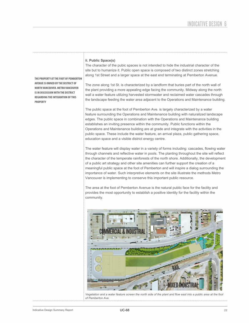
THE PROPERTY AT THE FOOT OF PEMBERTON AVENUE IS OWNED BY THE DISTRICT OF NORTH VANCOUVER. METRO VANCOUVER IS IN DISCUSSION WITH THE DISTRICT REGARDING THE INTEGRATION OF THIS PROPERTY
ii. Public Space(s)The character of the pubic spaces is not intended to hide the industrial character of the site but to humanize it. Public open space is composed of two distinct zones stretching along 1st Street and a larger space at the east end terminating at Pemberton Avenue.
The zone along 1st St. is characterized by a landform that buries part of the north wall of the plant providing a more appealing edge facing the community. Midway along the north wall a water feature utilizing harvested stormwater and reclaimed water cascades through the landscape feeding the water area adjacent to the Operations and Maintenance building.
The public space at the foot of Pemberton Ave. is largely characterized by a water feature surrounding the Operations and Maintenance building with naturalized landscape edges. The public space in combination with the Operations and Maintenance building establishes an inviting presence within the community. Public functions within the Operations and Maintenance building are at grade and integrate with the activities in the public space. These include the water feature, an arrival plaza, public gathering space, education space and a visible district energy centre.
The water feature will display water in a variety of forms including: cascades, flowing water through channels and reflective water in pools. The planting throughout the site will reflect the character of the temperate rainforests of the north shore. Additionally, the development of a public art strategy and other site amenities can further support the creation of a meaningful public space at the foot of Pemberton and will inspire a dialog surrounding the importance of water. Such interpretive elements on the site illustrate the methods Metro Vancouver is implementing to conserve this important public resource.
The area at the foot of Pemberton Avenue is the natural public face for the facility and provides the most opportunity to establish a positive identity for the facility within thecommunity.
Vegetation and a water feature screen the north side of the plant and flow east into a public area at the foot of Pemberton Ave.
COMMERCIAL & INDUSTRIAL
MIXED INDUSTRIAL
RAIL
UC-68
23
6 INDICATIVE DESIGN
Indicative Design Summary Report
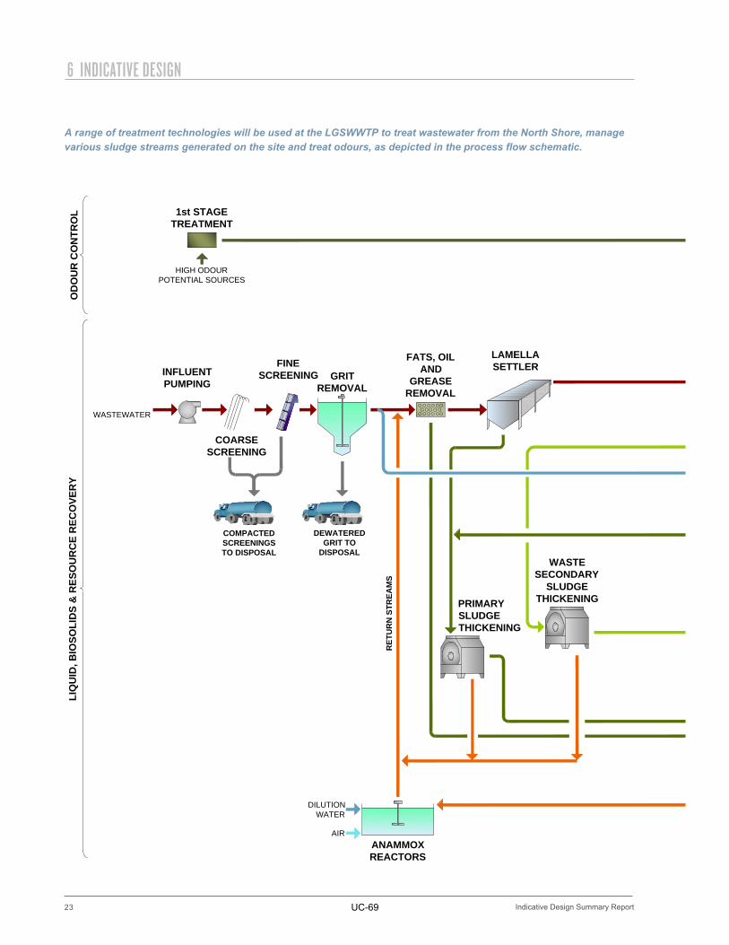
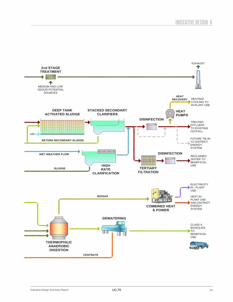
A range of treatment technologies will be used at the LGSWWTP to treat wastewater from the North Shore, manage various sludge streams generated on the site and treat odours, as depicted in the process flow schematic.
RAWWASTEWATER
COARSESCREENING
GRITREMOVAL
FINESCREENINGINFLUENT
PUMPING
WASTESECONDARY
SLUDGETHICKENING
1st STAGETREATMENT
HIGH ODOURPOTENTIAL SOURCES
DEWATEREDGRIT TO
DISPOSAL
LAMELLASETTLER
ANAMMOXREACTORS
OD
OU
R C
ON
TRO
LLI
QU
ID, B
IOSO
LID
S &
RES
OU
RC
E R
ECO
VER
Y
FATS, OILAND
GREASEREMOVAL
PRIMARYSLUDGETHICKENING
AIR
DILUTIONWATER
RET
UR
N S
TREA
MS
COMPACTEDSCREENINGSTO DISPOSAL
UC-69
24
INDICATIVE DESIGN 6
Indicative Design Summary Report
RAWWASTEWATER
COARSESCREENING
GRITREMOVAL
FINESCREENING INFLUENT
PUMPING
WASTESECONDARY
SLUDGETHICKENING
1st STAGETREATMENT
HIGH ODOURPOTENTIAL SOURCES
DEWATEREDGRIT TODISPOSAL
LAMELLASETTLER
ANAMMOXREACTORS
ODOUR CONTROL
LIQUID, BIOSOLIDS & RESOURCE RECOVERY
FATS, OILAND
GREASEREMOVAL
PRIMARYSLUDGETHICKENING
AIR
DILUTIONWATER
RETURN STREAMS
COMPACTEDSCREENINGSTO DISPOSAL
UC-70
25
6 INDICATIVE DESIGN
Indicative Design Summary Report
3 . T R E AT M E N T T E C H N O L O G Y
3 A . L I Q U I D T R E AT M E N TThe liquid treatment train includes the following six major components:
1. Influent pumping2. Preliminary treatment3. Primary treatment4. Secondary treatment5. High rate clarification6. Disinfection
i. Influent PumpingWastewater will be conveyed to LGSWWTP in trunk sewers to the Influent Pump Station. The Influent Pump Station will pump the wastewater directly above to the preliminary treatment process. LGSWWTP has been designed to allow wastewater to flow through the entire liquid treatment train and outfall to Burrard Inlet by gravity without additional pumping.
ii. Preliminary TreatmentThe role of preliminary treatment is to remove debris, such as plastics, rags, grit and fats, oils and grease (FOG), from the raw wastewater to prevent damage to downstream equipment, particularly high speed rotating equipment such as pumps. After the screenings and grit removal processes, wastewater will next enter a tank that is gently aerated with pressurized air to remove FOG that will coalesce and float to the surface of the tank. FOG is a high energy feedstock and it will be collected and pumped directly to the solids treatment train.
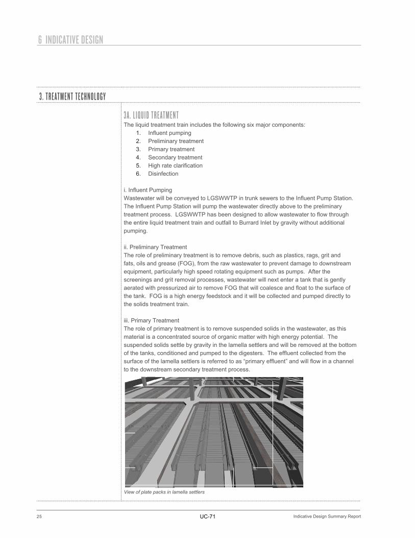
iii. Primary TreatmentThe role of primary treatment is to remove suspended solids in the wastewater, as this material is a concentrated source of organic matter with high energy potential. The suspended solids settle by gravity in the lamella settlers and will be removed at the bottom of the tanks, conditioned and pumped to the digesters. The effluent collected from the surface of the lamella settlers is referred to as “primary effluent” and will flow in a channel to the downstream secondary treatment process.
View of plate packs in lamella settlers
UC-71
26
INDICATIVE DESIGN 6
Indicative Design Summary Report
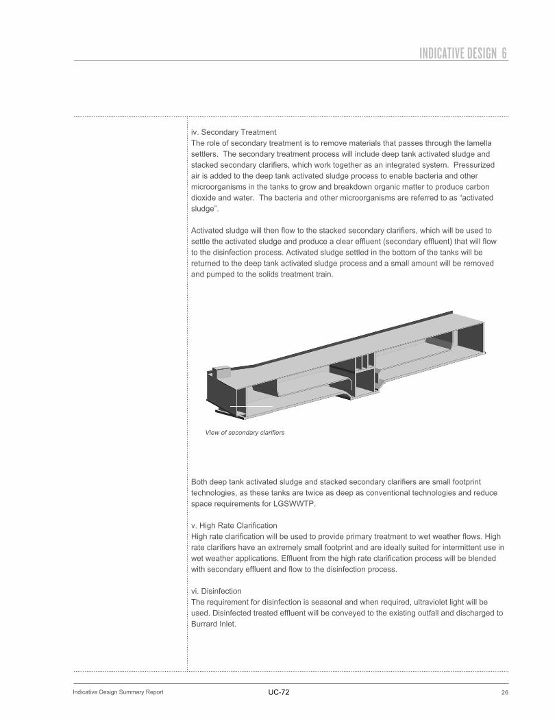
iv. Secondary TreatmentThe role of secondary treatment is to remove materials that passes through the lamella settlers. The secondary treatment process will include deep tank activated sludge and stacked secondary clarifiers, which work together as an integrated system. Pressurized air is added to the deep tank activated sludge process to enable bacteria and other microorganisms in the tanks to grow and breakdown organic matter to produce carbon dioxide and water. The bacteria and other microorganisms are referred to as “activated sludge”.
Activated sludge will then flow to the stacked secondary clarifiers, which will be used to settle the activated sludge and produce a clear effluent (secondary effluent) that will flow to the disinfection process. Activated sludge settled in the bottom of the tanks will be returned to the deep tank activated sludge process and a small amount will be removed and pumped to the solids treatment train.
Both deep tank activated sludge and stacked secondary clarifiers are small footprint technologies, as these tanks are twice as deep as conventional technologies and reduce space requirements for LGSWWTP.
v. High Rate ClarificationHigh rate clarification will be used to provide primary treatment to wet weather flows. High rate clarifiers have an extremely small footprint and are ideally suited for intermittent use in wet weather applications. Effluent from the high rate clarification process will be blended with secondary effluent and flow to the disinfection process.
vi. DisinfectionThe requirement for disinfection is seasonal and when required, ultraviolet light will be used. Disinfected treated effluent will be conveyed to the existing outfall and discharged to Burrard Inlet.
View of secondary clarifiers
UC-72
27
6 INDICATIVE DESIGN
Indicative Design Summary Report
3 B . S O L I D S M A N A G E M E N TThe solids treatment train includes the following three major components:
1. Thickening2. Digestion3. Dewatering and truck loading
i. ThickeningMechanical thickening will be used to remove water from the primary and secondary sludge streams to reduce their volume and minimize the size and footprint of solids treatment processes. After thickening, the sludge streams will be blended, pre-heated and pumped to the digestion process.
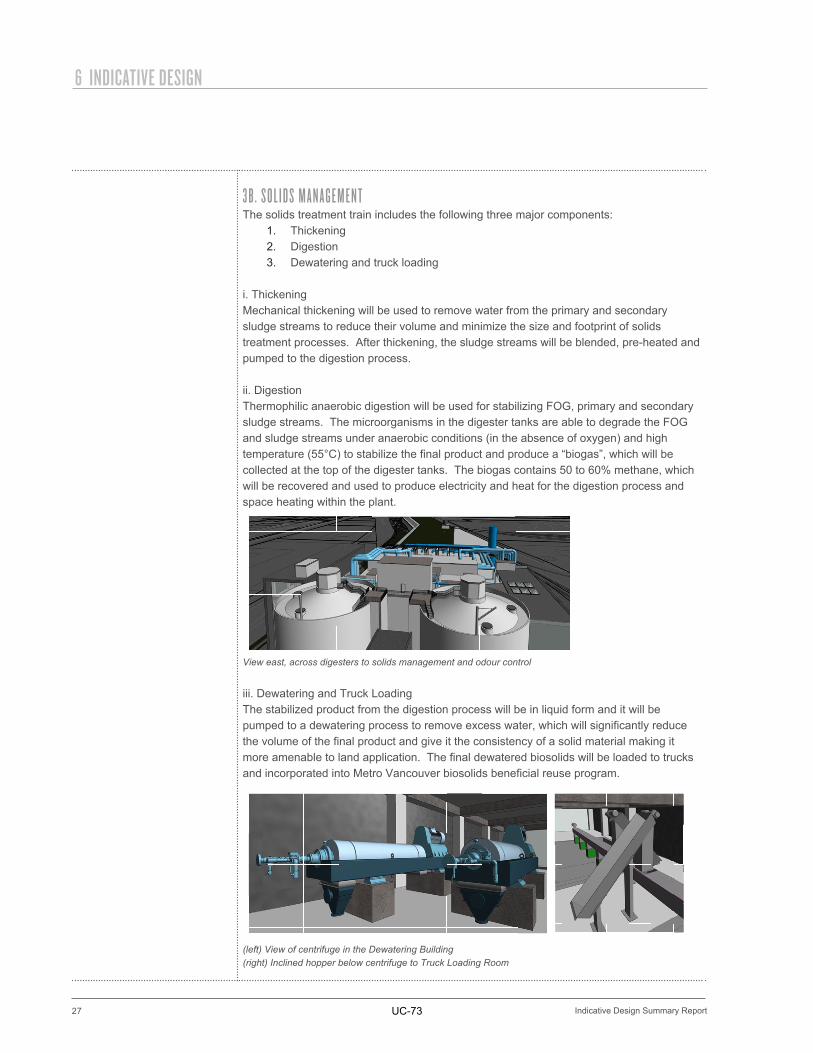
ii. DigestionThermophilic anaerobic digestion will be used for stabilizing FOG, primary and secondary sludge streams. The microorganisms in the digester tanks are able to degrade the FOG and sludge streams under anaerobic conditions (in the absence of oxygen) and high temperature (55°C) to stabilize the final product and produce a “biogas”, which will be collected at the top of the digester tanks. The biogas contains 50 to 60% methane, which will be recovered and used to produce electricity and heat for the digestion process and space heating within the plant.
View east, across digesters to solids management and odour control
iii. Dewatering and Truck LoadingThe stabilized product from the digestion process will be in liquid form and it will be pumped to a dewatering process to remove excess water, which will significantly reduce the volume of the final product and give it the consistency of a solid material making it more amenable to land application. The final dewatered biosolids will be loaded to trucks and incorporated into Metro Vancouver biosolids beneficial reuse program.
(left) View of centrifuge in the Dewatering Building(right) Inclined hopper below centrifuge to Truck Loading Room
UC-73
28
INDICATIVE DESIGN 6
Indicative Design Summary Report
PRINCIPLES OF ODOUR CONTROL:1. PREVENTION2. CONTAINMENT3. TREATMENT4. DISPERSION
STAGES OF TREATMENT:1. BIOTOWERS2. ACTIVATED CARBON POLISHING
ACTIVATED CARBON POLISHING HAS A DECADES LONG TRACK-RECORD FOR ODOUR TREATMENT AND IS PARTICULARLY ADEPT AT REMOVING ODOROUS COMPOUNDS.
3 C . O D O U R C O N T R O L
PreventionProvisions will be included in the design to minimize the release of odours from the water phase to gas phase, such as minimizing turbulence in channels, tanks and launders. Good housekeeping practices, such as minimizing the accumulation of septic sludge in tanks will further help prevent the formation of odours.
ContainmentAll potential sources of odour will be contained by physical covers and the air within the containment barriers will be discharged to the odour treatment system. An additional level of secondary containment will be provided with enclosures around all components of LGSWWTP. The air within the secondary containment system will also be discharged to the odour treatment system.
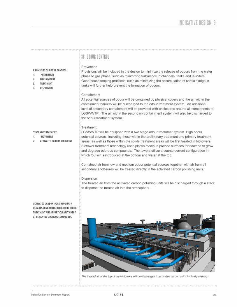
TreatmentLGSWWTP will be equipped with a two stage odour treatment system. High odour potential sources, including those within the preliminary treatment and primary treatment areas, as well as those within the solids treatment areas will be first treated in biotowers. Biotower treatment technology uses plastic media to provide surfaces for bacteria to grow and degrade odorous compounds. The towers utilize a countercurrent configuration in which foul air is introduced at the bottom and water at the top.
Contained air from low and medium odour potential sources together with air from all secondary enclosures will be treated directly in the activated carbon polishing units.
DispersionThe treated air from the activated carbon polishing units will be discharged through a stack to disperse the treated air into the atmosphere.
The treated air at the top of the biotowers will be discharged to activated carbon units for final polishing.
UC-74
29
6 INDICATIVE DESIGN
Indicative Design Summary Report
3 D . N O I S E M A N A G E M E N TAll significant noise emission sources, including rotating equipment and motors will be located within buildings or enclosures and acoustically insulated, as required to attenuate noise emissions. All louvers for the ventilation system will be similarly treated to attenuate noise emissions. LGSWWTP will comply with the District of North Vancouver’s Noise Bylaw.
3 E . P O W E R R E L I A B I L I T YLGSWWTP requires reliable sources of electricity to ensure that life safety systems and critical treatment processes are in operation to meet effluent discharge limits. The primary source of electricity will be provided from BC Hydro’s electricity grid on the North Shore. A second source of electricity will be produced and utilized within the plant by a cogeneration facility. Standby power will also be provided with dedicated diesel generators, which will be used in the event of power outages.
The BC Building Code designates wastewater treatment plants as post-disaster facilities, which has important implications for the design of buildings and power reliability. The standby diesel generators will also be used to satisfy the requirements of a post-disaster facility. In the event of a disaster, such as an earth quake, priority will be given to provide electricity for the following:
• Critical life safety systems• Influent pumping• Preliminary treatment• Primary treatment• Primary sludge pumping• Disinfection
UC-75
30
INDICATIVE DESIGN 6
Indicative Design Summary Report
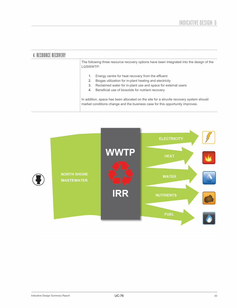
4 . R E S O U R C E R E C O V E R YThe following three resource recovery options have been integrated into the design of the LGSWWTP:
1. Energy centre for heat recovery from the effluent2. Biogas utilization for in-plant heating and electricity3. Reclaimed water for in-plant use and space for external users4. Beneficial use of biosolids for nutrient recovery
In addition, space has been allocated on the site for a struvite recovery system should market conditions change and the business case for this opportunity improves.
UC-76
31
6 INDICATIVE DESIGN
Indicative Design Summary Report
5 . C O N V E YA N C E
The majority of wastewater generated on the North Shore will discharge to LGSWWTP via the North Vancouver Interceptor on West 1st Street. The North Vancouver Interceptor will be diverted to the Influent Pump Station when the new infrastructure is ready to be put into service. Infrastructure improvements will be required to convey wastewater from the District of West Vancouver, Squamish Nation and the District of North Vancouver to LGSWWTP. Also, a pipeline will be required to convey treated effluent to the existing outfall at First Narrows. The final siting and alignment of this infrastructure is to be determined.
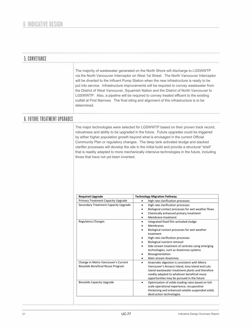
6 . F U T U R E T R E AT M E N T U P G R A D E SThe major technologies were selected for LGSWWTP based on their proven track record, robustness and ability to be upgraded in the future. Future upgrades could be triggered by either higher population growth beyond what is envisaged in the current Official Community Plan or regulatory changes. The deep tank activated sludge and stacked clarifier processes will develop the site in the initial build and provide a structural “shell” that is readily adapted to more mechanically intensive technologies in the future, including those that have not yet been invented.
Required Upgrade Technology Migration Pathway Primary Treatment Capacity Upgrade • High rate clarification processes Secondary Treatment Capacity Upgrade • High rate clarification processes
• Biological contact processes for wet weather flows • Chemically enhanced primary treatment • Membrane treatment
Regulatory Changes • Integrated fixed film activated sludge • Membranes • Biological contact processes for wet weather
treatment • High rate clarification processes • Biological nutrient removal • Side stream treatment of centrate using emerging
technologies, such as Anammox systems • Bioaugmentation • Main stream Anammox
Change in Metro Vancouver’s Current Biosolids Beneficial Reuse Program
• Anaerobic digestion is consistent with Metro Vancouver’s Annacis Island, Iona Island and Lulu Island wastewater treatment plants and therefore readily adapted to whatever beneficial reuse opportunities may be pursued in the future
Biosolids Capacity Upgrade • Optimization of solids loading rates based on full-scale operational experience, recuperative thickening and enhanced volatile suspended solids destruction technologies
UC-77

UC-79
32
PROJECT IMPLEMENTATION SCHEDULE 7
Indicative Design Summary Report
1 . S C H E D U L E
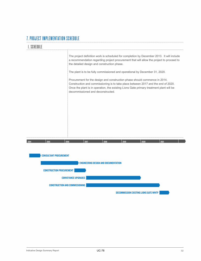
The project definition work is scheduled for completion by December 2013. It will include a recommendation regarding project procurement that will allow the project to proceed to the detailed design and construction phase.
The plant is to be fully commissioned and operational by December 31, 2020.
Procurement for the design and construction phase should commence in 2014. Construction and commissioning is to take place between 2017 and the end of 2020. Once the plant is in operation, the existing Lions Gate primary treatment plant will be decommissioned and deconstructed.
7. P R O J E C T I M P L E M E N TAT I O N S C H E D U L E
2014 2015 2016 2017 2021202020192018
CONSULTANT PROCUREMENT
ENGINEERING DESIGN AND DOCUMENTATION
CONSTRUCTION PROCUREMENT
CONVEYANCE UPGRADES
CONSTRUCTION AND COMMISSIONING
DECOMMISSION EXISTING LIONS GATE WWTP
UC-78