Embed Size (px)
Citation preview
ISP/IXP Networking Workshop Lab
1
Module 1 – Basic Topology, OSPF and iBGP
Objective: Create a basic physical lab interconnection with one OSPF Area and one BGP AS number. Ensure that all routers, interfaces, cables and connections are working properly. Prerequisites: Knowledge of Cisco router CLI, previous hands on experience. The following will be the common topology used for the first series of labs.
Figure 1 – ISP Lab Basic Configuration

Monday, July 21, 2008
Cisco Systems Inc 2 170 West Tasman Drive. San Jose, CA 95134-1706 Phone: +1 408 526-4000 Fax: +1 408 536-4100
Lab Notes This workshop is intended to be run on routers using service provider IOS. The configurations and configuration principles discussed below will work on 12.0S and all releases starting with 12.2 of Cisco IOS built from April 2003 onwards. Older IOS releases are not supported (and indeed not recommended for use as Internet infrastructure). The purpose of this module is to construct the workshop lab and introduce everyone to the basic principles of constructing and configuring a network. An important point to remember, and one that will be emphasised time and again through out this workshop, is that there is a distinct sequence to building an operational network: After the physical design is established, the connections between the hardware should be built and
verified. Next, the routers should have the base configuration installed, and basic but sufficient security
should be set up. Next the basic IP connectivity be tested and proven. This means assigning IP addresses on all
links which are to be used, and testing the links to the neighbouring devices. Only once one router can see its neighbour does it make sense to start configuring routing
protocols. And start with the IGP (OSPF is chosen for this workshop). There is no purpose to building BGP while the chosen IGP (in this case OSPF) is not functioning properly. BGP relies on OSPF to find its neighbours and next hops, and an improperly or non-functioning OSPF will result in much time wasted attempting to debug routing problems.
Once the IGP is functioning properly, the BGP configuration can be started, first internal BGP,
then external BGP. Remember to RTFM. What is RTFM? It is critical that ISP Network Engineers fully utilise all
information resources. The #1 source is the documentation. Read The F#$% Manual (RTFM) is the traditional phase used to inform engineers that the answer is the documentation and go read it. We will use RTFM through out these exercises to highlight areas where the student should use the documentation for further deepening. There will be many new commands. Please refer to the Cisco Documentation CD for details on each of these commands.
Finally, documentation. Documentation is often overlooked or forgotten. It is an ongoing process
in this workshop. If the instructor asks you to document something, either on the whiteboard in the class, or at the back of this booklet, it is in your best interests to do so. There can never be too much documentation, and documentation at the time of network design and construction can usually saves much frustration at a future date or event.
To explain Figure 1 in more detail:
• fe0/0 and fe0/1 refer to the 1st and 2nd fastethernet interfaces on the router. • s0/0 and s0/1 refer to the 1st and 2nd synchronous serial interfaces on the router. Depending on
the model, these may actually appear on the router as serial 0/1/0 and serial 0/2/0 respectively. • Each router has an RJ-45 style console port, as well as an auxiliary port – the console cable to
the PC needs to be connected to the console port of the router.
ISP/IXP Networking Workshop Lab
3
• Router15 is the router used by the lab instructors during various exercises throughout the workshop. The instructors will tell you if any configuration is required.
Lab Exercise 1. Routers and the Workshops participants. This workshop is laid out such that a group of two
students will operate a single router. 14 routers generally imply at least 28 participants. For workshops with larger numbers of participants, groups of three should configure a single router. The Workshop Instructors will divide the routers amongst the workshop participants. In the following notes, a “router team” refers to the group assigned to one particular router.
2. Router Hostname. Each router will be named according to the table location, Router1, Router2,
Router3, etc. Documentation and labs will also refer to Router1 as R1. At the router prompt, first go into enable mode, then enter “config terminal”, or simply “config” by itself:
Router> enable Router# config terminal Enter configuration commands, one per line. End with CNTL/Z. Router(config)# hostname Router1 Router1(config)#
3. Turn Off Domain Name Lookups. Cisco routers will always try to look up the DNS for any
name or address specified in the command line. You can see this when doing a trace on a router with no DNS server or a DNS server with no in-addr.arpa entries for the IP addresses. We will turn this lookup off for the labs for the time being to speed up traceroutes.
Router1 (config)# no ip domain-lookup
4. Disable Command-line Name Resolution. The router by default attempts to use the various transports it supports to resolve the commands entered into the command line during normal and configuration modes. If the commands entered are not part of Cisco IOS, the router will attempt to use its other supported transports to interpret the meaning of the name. For example, if the command entered is an IP address, the router will automatically try to connect to that remote destination. This feature is undesirable on an ISP router as it means that typographical errors can result in connections being attempted to remote systems, or time outs while the router tries to use the DNS to translate the name, and so on.
Router1 (config)# line con 0 Router1 (config-line)# transport preferred none Router1 (config-line)# line vty 0 4 Router1 (config-line)# transport preferred none
5. Disable Source Routing. Unless you really believe there is a need for it, source routing should be
disabled. This option, enabled by default, allows the router to process packets with source routing header options. This feature is a well-known security risk as it allows remote sites to send packets with different source address through the network (this was useful for troubleshooting networks from different locations on the Internet, but in recent years has been widely abused for miscreant activities on the Internet).
Monday, July 21, 2008
Cisco Systems Inc 4 170 West Tasman Drive. San Jose, CA 95134-1706 Phone: +1 408 526-4000 Fax: +1 408 536-4100
Router1 (config)# no ip source-route 6. Usernames and Passwords. All router usernames and passwords should be cisco. Please do not
change the username or password to anything else, or leave the password unconfigured (access to vty ports is not possible if no password is set). It is essential for a smooth operating lab that all participants have access to all routers.
Router1 (config(# username cisco secret cisco Router1 (config)# enable secret cisco Router1 (config)# service password-encryption
The service password-encryption directive tells the router to encrypt all passwords stored in the router’s configuration (apart from enable secret which is already encrypted). Note A: while we use username cisco and many instances of a password of cisco in these workshops, under no circumstances must any service provider operator ever use easily guessable passwords as these on their live operational network1. Note B: for IOS releases prior to 12.3, the username/secret pair is not available, and operators will have to configure username/password instead. The latter format uses type 7 encryption, whereas the former is the more secure md5 based encryption. Please see the Cisco ISP Essentials presentation for more details.
7. Enabling login access for other teams. In order to let other teams telnet into your router in future
modules of this workshop, you need to configure a password for all virtual terminal lines.
Router1 (config)# aaa new-model Router1 (config)# aaa authentication login default local Router1 (config)# aaa authentication enable default enable
This series of commands tells the router to look locally for standard user login (the username password pair set earlier), and to the locally configured enable secret for the enable login. By default, login will be enabled on all vtys for other teams to gain access.
8. Configure system logging. A vital part of any Internet operational system is to record logs. The
router by default will display system logs on the router console. However, this is undesirable for Internet operational routers, as the console is a 9600 baud connection, and can place a high processor interrupt load at the time of busy traffic on the network. However, the router logs can also be recorded into a buffer on the router – this takes no interrupt load and it also enables to operator to check the history of what events happened on the router. In a future module, the lab will configuration the router to send the log messages to a SYSLOG server.
Router1 (config)# no logging console
Router1 (config)# logging buffer 8192 debug
which disables console logs and instead records all logs in a 8192byte buffer set aside on the router. To see the contents of this internal logging buffer at any time, the command “sh log” should be used at the command prompt.
1 This sentence cannot be emphasized enough. It is quite common for attackers to gain access to networks simply because operators have used familiar or easily guessed passwords.
ISP/IXP Networking Workshop Lab
5
9. Save the Configuration. With the basic configuration in place, save the configuration. To do this,
exit from enable mode by typing “end” or “<ctrl> Z”, and at the command prompt enter “write memory”.
Router1(config)#^Z Router1# write memory Building configuration... [OK] Router1#
It is highly recommended that the configuration is saved quite frequently to NVRAM, especially in the workshop environment where it is possible for power cables to become dislodged. If the configuration is not saved to NVRAM, any changes made to the running configuration will be lost after a power cycle. Log off the router by typing exit, and then log back in again. Notice how the login sequence has changed, prompting for a “username” and “password” from the user. Note that at each checkpoint in the workshop, you should save the configuration to memory – remember that powering the router off will result in it reverting to the last saved configuration in NVRAM.
10. IP Addresses. For the purposes of this Module we are going to assume that each router team is an
ISP. In the operational Internet, ISPs are allocated address space by the Regional Internet Registries – we are going to assume that the minimum allocation for this workshop is a /20. So each router team receives a /20 worth of address space. The teams running Routers 3 and 10 receive a /19 worth address space – not because they are special, but because it helps with the exercises later on in the workshop. The following table lists the address allocations made.
R1 100.1.0.0/20 R2 100.1.16.0/20 R3 100.1.32.0/19 R4 100.2.0.0/20 R5 100.2.16.0/20 R6 100.2.32.0/20 R7 100.2.48.0/20
R8 100.3.0.0/20 R9 100.3.16.0/20 R10 100.3.32.0/19 R11 100.4.0.0/20 R12 100.4.16.0/20 R13 100.4.32.0/20 R14 100.4.48.0/20
Make a separate note separate from this work book of the address block assigned to your router – reference will be made to it several times throughout the rest of this workshop. Unless, of course, you like searching back through this booklet to find this page.
11. Back to Back Serial Connections. Connect the serial connections as in Figure 1. IP addresses for the point to point links will be worked out between each Router Team. For instance, Router Team 1 and Router Team 3 will need to discuss with each other which part of which team’s address block will be used for the serial point to point link between them. (See the Addressing Plan for this module in the Appendices.)
The DCE side of a back to back serial connection is configured with the clock rate command that drives the serial circuit. (Older versions of IOS used the clockrate command, now hidden but still functional.) Physically check the cable to see which side is DCE and which is DTE. On some routers, the command show controller <interface> will show DCE/DTE status. For
Monday, July 21, 2008
Cisco Systems Inc 6 170 West Tasman Drive. San Jose, CA 95134-1706 Phone: +1 408 526-4000 Fax: +1 408 536-4100
example, on a Cisco 3620, show controllers serial 0/0 will produce a result that will display whether the cable connected to serial 0/0 is a DTE or DCE. Once the DTE and DCE cables have been determined and the clock rate command has been applied, configure the IP address and other recommended BCP commands that are recommended for each ISP’s Interface:
Router2(config)# interface serial 0 Router2(config-if)# ip address 100.1.17.1 255.255.255.252 Router2(config-if)# description 2 Mbps Link to Router4 via DTE/DCE Serial Router2(config-if)# bandwidth 2000 Router2(config-if)# clock rate 2000000 Router2(config-if)# no ip redirects Router2(config-if)# no ip directed-broadcast Router2(config-if)# no ip proxy-arp Router2(config-if)# no shutdown
NOTE: The lab instructors will have drawn a large network map on the white-board in the workshop lab. When the IP addresses are assigned, please annotate them and inform the instructor. All the point to point links MUST be annotated there so that other Router Teams can document and understand the links and routing in this and future modules. Q: What network mask should be used on point-to-point links? A: On serial interfaces, the network mask should be /30 (or 255.255.255.252 in dotted quad format). There is no point in using any other size of mask as there are only two hosts on such a link. A 255.255.255.252 address mask means 4 available host addresses, of which two are usable (the other two representing network and broadcast addresses).
12. Ethernet Connections. The Ethernet links between the routers will be made using cross-over RJ-45 cables – these will directly connect the Ethernet ports on the two routers without the requirement for an Ethernet switch. IP subnets will be worked out between the Router Teams (again see the Addressing Plan). Don’t make the mistake of assigning a /24 mask to the interface address – there are only two hosts on the Ethernet connecting the two routers, so a /30 mask should be more than sufficient.
13. Ping Test #1. Ping all physically connected subnets of the neighbouring routers. If the physically
connected subnets are unreachable, consult with your neighbouring teams as to what might be wrong. Don’t ignore the problem – it may not go away. Use the following commands to troubleshoot the connection:
show arp : Shows the Address resolution protocol show interface <interface> <number> : Interface status and configuration show ip interface : Brief summary of IP interface status and configuration
14. Create Loopback Interfaces. Loopback interfaces will be used in this workshop for many things.
These include generating routes (to be advertised) and configuring some BGP peerings. Each Router Team will use part of their IP address block for loopback interfaces. Most ISPs tend to set aside a contiguous block of addresses for use by their router loopbacks. For example, if an ISP had 20 routers, they would need a /27 (or 32 host addresses) to provide a loopback address for each router. Here are suggestions for the network blocks each router team should use for loopback addresses (these lab notes assume these assignments in all examples):
ISP/IXP Networking Workshop Lab
7
R1 100.1.15.224/27 R2 100.1.31.224/27 R3 100.1.63.224/27 R4 100.2.15.224/27 R5 100.2.31.224/27 R6 100.2.47.224/27 R7 100.2.63.224/27
R8 100.3.15.224/27 R9 100.3.31.224/27 R10 100.3.63.224/27 R11 100.4.15.224/27 R12 100.4.31.224/27 R13 100.4.47.224/27 R14 100.4.63.224/27
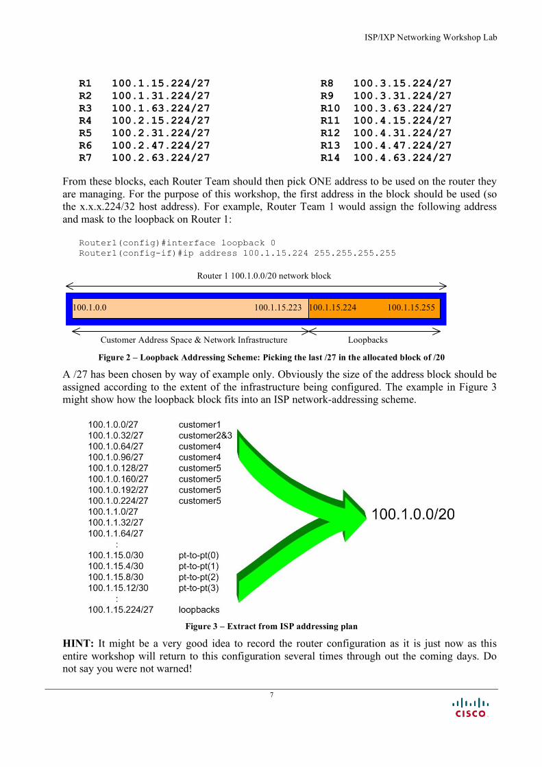
From these blocks, each Router Team should then pick ONE address to be used on the router they are managing. For the purpose of this workshop, the first address in the block should be used (so the x.x.x.224/32 host address). For example, Router Team 1 would assign the following address and mask to the loopback on Router 1:
Router1(config)#interface loopback 0 Router1(config-if)#ip address 100.1.15.224 255.255.255.255
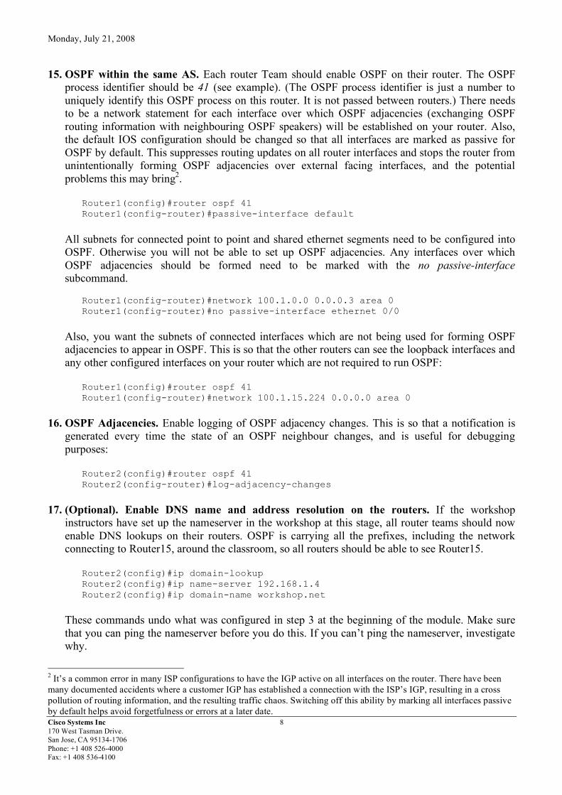
Figure 2 – Loopback Addressing Scheme: Picking the last /27 in the allocated block of /20 A /27 has been chosen by way of example only. Obviously the size of the address block should be assigned according to the extent of the infrastructure being configured. The example in Figure 3 might show how the loopback block fits into an ISP network-addressing scheme.
Figure 3 – Extract from ISP addressing plan
HINT: It might be a very good idea to record the router configuration as it is just now as this entire workshop will return to this configuration several times through out the coming days. Do not say you were not warned!
100.1.15.223 100.1.0.0 100.1.15.224 100.1.15.255
Loopbacks Customer Address Space & Network Infrastructure
Router 1 100.1.0.0/20 network block
Monday, July 21, 2008
Cisco Systems Inc 8 170 West Tasman Drive. San Jose, CA 95134-1706 Phone: +1 408 526-4000 Fax: +1 408 536-4100
15. OSPF within the same AS. Each router Team should enable OSPF on their router. The OSPF process identifier should be 41 (see example). (The OSPF process identifier is just a number to uniquely identify this OSPF process on this router. It is not passed between routers.) There needs to be a network statement for each interface over which OSPF adjacencies (exchanging OSPF routing information with neighbouring OSPF speakers) will be established on your router. Also, the default IOS configuration should be changed so that all interfaces are marked as passive for OSPF by default. This suppresses routing updates on all router interfaces and stops the router from unintentionally forming OSPF adjacencies over external facing interfaces, and the potential problems this may bring2.
Router1(config)#router ospf 41 Router1(config-router)#passive-interface default
All subnets for connected point to point and shared ethernet segments need to be configured into OSPF. Otherwise you will not be able to set up OSPF adjacencies. Any interfaces over which OSPF adjacencies should be formed need to be marked with the no passive-interface subcommand.
Router1(config-router)#network 100.1.0.0 0.0.0.3 area 0 Router1(config-router)#no passive-interface ethernet 0/0
Also, you want the subnets of connected interfaces which are not being used for forming OSPF adjacencies to appear in OSPF. This is so that the other routers can see the loopback interfaces and any other configured interfaces on your router which are not required to run OSPF:
Router1(config)#router ospf 41 Router1(config-router)#network 100.1.15.224 0.0.0.0 area 0
16. OSPF Adjacencies. Enable logging of OSPF adjacency changes. This is so that a notification is
generated every time the state of an OSPF neighbour changes, and is useful for debugging purposes:
Router2(config)#router ospf 41 Router2(config-router)#log-adjacency-changes
17. (Optional). Enable DNS name and address resolution on the routers. If the workshop
instructors have set up the nameserver in the workshop at this stage, all router teams should now enable DNS lookups on their routers. OSPF is carrying all the prefixes, including the network connecting to Router15, around the classroom, so all routers should be able to see Router15.
Router2(config)#ip domain-lookup Router2(config)#ip name-server 192.168.1.4 Router2(config)#ip domain-name workshop.net
These commands undo what was configured in step 3 at the beginning of the module. Make sure that you can ping the nameserver before you do this. If you can’t ping the nameserver, investigate why.
2 It’s a common error in many ISP configurations to have the IGP active on all interfaces on the router. There have been many documented accidents where a customer IGP has established a connection with the ISP’s IGP, resulting in a cross pollution of routing information, and the resulting traffic chaos. Switching off this ability by marking all interfaces passive by default helps avoid forgetfulness or errors at a later date.
ISP/IXP Networking Workshop Lab
9
Note that the team operating Router 6 will be added to add configuration which will allow the DNS server address block to be propagated throughout the classroom network. The extra configuration for Router6 is as follows:
router ospf 41 network 192.168.1.0 0.0.0.255 area 0 ! interface Ethernet0/1 ip addr 192.168.1.254 255.255.255.0 no shutdown !
18. (Optional). Enable OSPF name lookups on the routers. Following from the previous step, now
enable OSPF name lookups on the router.
Router2(config)#ip ospf name-lookup
This command enables the display of the OSPF router-ids as domain names. So, rather than displaying the following output with name lookups disabled: router2>sh ip ospf neigh Neighbor ID Pri State Dead Time Address Interface 100.1.15.224 1 FULL/BDR 00:00:36 100.1.0.1 Ethernet0/0 100.2.15.224 1 FULL/ - 00:00:32 100.1.17.2 Serial0/0 100.4.63.224 1 FULL/DR 00:00:38 100.1.18.2 Ethernet0/1
the router will display the following: router2#sh ip ospf neigh Neighbor ID Pri State Dead Time Address Interface router1.worksho 1 FULL/BDR 00:00:33 100.1.0.1 Ethernet0/0 router4.worksho 1 FULL/ - 00:00:39 100.1.17.2 Serial0/0 router14.worksh 1 FULL/DR 00:00:35 100.1.18.2 Ethernet0/1 which is much more informative. 19. Ping Test #2. Ping all loopback interfaces in the classroom. This will ensure the OSPF IGP is
connected End-to-End. If there are problems, use the following commands to help determine the problem:
show ip route : see if there is a route for the intended destination show ip ospf : see general OSPF information show ip ospf interface : Check if OSPF is enabled on all intended interface show ip ospf neighbor : see a list of OSPF neighbours that the router sees
Checkpoint #1: call lab assistant to verify the connectivity. Save the configuration as it is on the router – use a separate worksheet, or the workspace at the end of this Module. You will require this configuration several times throughout the workshop.
Monday, July 21, 2008
Cisco Systems Inc 10 170 West Tasman Drive. San Jose, CA 95134-1706 Phone: +1 408 526-4000 Fax: +1 408 536-4100
20. Configuring iBGP. Before we set up iBGP with our neighbours in our AS, we need to do some basic preparation on the router. The IOS defaults are not optimised for Service Provider networks, so before we bring up BGP sessions, we should set the defaults that we require.
The default distance for eBGP is 20, the default distance for iBGP is 200, and the default distance for OSPF is 110. This means that there is a potential for a prefix learned by eBGP to override the identical prefix carried by OSPF. Recall from the Routing presentation that there is a distinct separation between BGP and OSPF processes – prefixes present in OSPF will never be found in BGP, and vice-versa. To protect against accidents3, the eBGP distance is set to 200 also. The command to do this is the bgp distance subcommand, syntax is:
distance bgp <external-routes> <internal-routes> <local-routes>
Note: This should be included in all future BGP configurations in this workshop. For example, for Router2, the configuration might be: Router2(config)#router bgp 10 Router2(config-router)#distance bgp 200 200 200
21. Logging of BGP Adjacency State. Enable logging of BGP neighbour changes. This is so that a
notification is generated every time the state of a BGP neighbour changes state, and is useful for debugging purposes: Router2(config)#router bgp 10 Router2(config-router)# bgp log-neighbor-changes
Note: From IOS 12.3 onwards, bgp log-neighbor-changes is activated by default when BGP is first configured.
22. Configuring iBGP Neighbours. All Routers will be in Autonomous System (AS) 10 for this first
lab. Use the show ip bgp summary to check the peering. The BGP peering will be established using the loopback interfaces’ IP address.
Router2(config)#router bgp 10 Router2 (config-router)#neighbor 100.1.15.224 remote-as 10 Router2 (config-router)#neighbor 100.1.15.224 update-source loopback 0 Router2 (config-router)#neighbor 100.1.15.224 description iBGP with Router1 Router2 (config-router)# Router2 (config-router)#neighbor 100.1.63.224 remote-as 10 Router2 (config-router)#neighbor 100.1.63.224 update-source loopback 0 Router2 (config-router)#neighbor 100.1.63.224 description iBGP with Router3 Router2 (config-router)# Router2 (config-router)#neighbor 100.2.15.224 remote-as 10 Router2 (config-router)#neighbor 100.2.15.224 update-source loopback 0 Router2 (config-router)#neighbor 100.2.15.224 description iBGP with Router4 Router2 (config-router)# Router2 (config-router)#neighbor 100.2.31.224 remote-as 10 Router2 (config-router)#neighbor 100.2.31.224 update-source loopback 0 Router2 (config-router)#neighbor 100.2.31.224 description iBGP with Router5 Router2 (config-router)#
3 There have been several incidents in the past where denial of service attacks on ISP networks have been successful because ISPs have omitted basic routing protocol security. Setting the BGP distances to be greater than any IGP is one of the mitigation methods available.
ISP/IXP Networking Workshop Lab
11
Router2 (config-router)#neighbor 100.2.47.224 remote-as 10 Router2 (config-router)#neighbor 100.2.47.224 update-source loopback 0 Router2 (config-router)#neighbor 100.2.47.224 description iBGP with Router6 Router2 (config-router)# Router2 (config-router)#neighbor 100.2.63.224 remote-as 10 Router2 (config-router)#neighbor 100.2.63.224 update-source loopback 0 Router2 (config-router)#neighbor 100.2.63.224 description iBGP with Router7 Router2 (config-router)# Router2 (config-router)#neighbor 100.3.15.224 remote-as 10 Router2 (config-router)#neighbor 100.3.15.224 update-source loopback 0 Router2 (config-router)#neighbor 100.3.15.224 description iBGP with Router8 Router2 (config-router)# Router2 (config-router)#neighbor 100.3.31.224 remote-as 10 Router2 (config-router)#neighbor 100.3.31.224 update-source loopback 0 Router2 (config-router)#neighbor 100.3.31.224 description iBGP with Router9 Router2 (config-router)# Router2 (config-router)#neighbor 100.3.63.224 remote-as 10 Router2 (config-router)#neighbor 100.3.63.224 update-source loopback 0 Router2 (config-router)#neighbor 100.3.63.224 description iBGP with Router10 Router2 (config-router)# Router2 (config-router)#neighbor 100.4.15.224 remote-as 10 Router2 (config-router)#neighbor 100.4.15.224 update-source loopback 0 Router2 (config-router)#neighbor 100.4.15.224 description iBGP with Router11 Router2 (config-router)# Router2 (config-router)#neighbor 100.4.31.224 remote-as 10 Router2 (config-router)#neighbor 100.4.31.224 update-source loopback 0 Router2 (config-router)#neighbor 100.4.31.224 description iBGP with Router12 Router2 (config-router)# Router2 (config-router)#neighbor 100.4.47.224 remote-as 10 Router2 (config-router)#neighbor 100.4.47.224 update-source loopback 0 Router2 (config-router)#neighbor 100.4.47.224 description iBGP with Router13 Router2 (config-router)# Router2 (config-router)#neighbor 100.4.63.224 remote-as 10 Router2 (config-router)#neighbor 100.4.63.224 update-source loopback 0 Router2 (config-router)#neighbor 100.4.63.224 description iBGP with Router14
Q. Why is update-source loopback 0 necessary on iBGP?
Use show ip bgp summary to check the status of the iBGP neighbour connections. If the iBGP session is not up and/or no updates are being sent, work with the Router Team for that neighbour connection to troubleshoot the problem.
23. Sanity Check. Remember to use the following commands to ensure you are getting the
information you are suppose to be getting:
show ip ospf : see general OSPF information show ip ospf interface : see a list of OSPF interfaces that the router sees show ip ospf neighbor : see a list of OSPF neighbours that the router sees show ip ospf database : see OSPF link state database that the router has learned show ip bgp summary : see a list of BGP peers that the router sees show ip bgp : see a list of BGP paths that the router sees show ip route : see all the routes that the router has installed
Q. Are there routes seen via show ip bgp? If not, why not? Are there any routes tagged "B" when you do a show ip route?
Monday, July 21, 2008
Cisco Systems Inc 12 170 West Tasman Drive. San Jose, CA 95134-1706 Phone: +1 408 526-4000 Fax: +1 408 536-4100
24. Add Networks via BGP. Each Router Team will use BGP to advertise the address block assigned to them earlier in the Module. For example, Router Team 1 would add:
Router1 (config)#router bgp 10 Router1 (config-router)#network 100.1.0.0 mask 255.255.240.0
Use show ip bgp on neighbour’s router to see if you are advertising your network via BGP.
Q. Does the network show up via BGP? If not, why? Enter a static route for the CIDR block. For example, Router 1 would use:
Router1 (config)#ip route 100.1.0.0 255.255.240.0 Null0
Q. Does the network show up via a neighbour’s BGP? Use the command show ip bgp neighbor <neighbour’s IP address> advertised-routes to see what you are exporting to the other router. Physically go to one of your neighbour’s routers and check their BGP Table. Explain what you see. Q. Does the network appear in the router’s forwarding table? Use the command show ip route to check the local forwarding table. If not, why not?
25. For Routers with IOS prior to 12.3 add the following commands to BGP:
Router1 (config)#router bgp 10 Router1 (config-router)# no synchronization Router1 (config-router)# no auto-summary
Q. Does the network appear in the router’s forwarding table? Use the command show ip route to check the local forwarding table. What does the no synchronisation command do in BGP? How does it effect the router’s forwarding table?
Note: As from IOS 12.3, synchronization and auto-summarisation are disabled by default and do not appear in the default BGP configuration. These two features have not been required in Service Provider networks since the classless routing system was introduced to the Internet in 1994.
Checkpoint #2 : call the lab assistant to verify the connectivity. 26. Traceroute to all routers. Once you can ping all the routers, try tracing routes to all the routers
using trace x.x.x.x command. For example, Router Team 1 would type:
Router1# trace 100.4.31.224
to trace a route to Router R12. If the trace times out each hop due to unreachable destinations, it is possible to interrupt the traceroute using the Cisco break sequence CTRL-^.
Q. Why do some trace paths show multiple IP addresses per hop?
A. If there are more than one equal cost paths, OSPF will “load share” traffic between those paths.
ISP/IXP Networking Workshop Lab
13
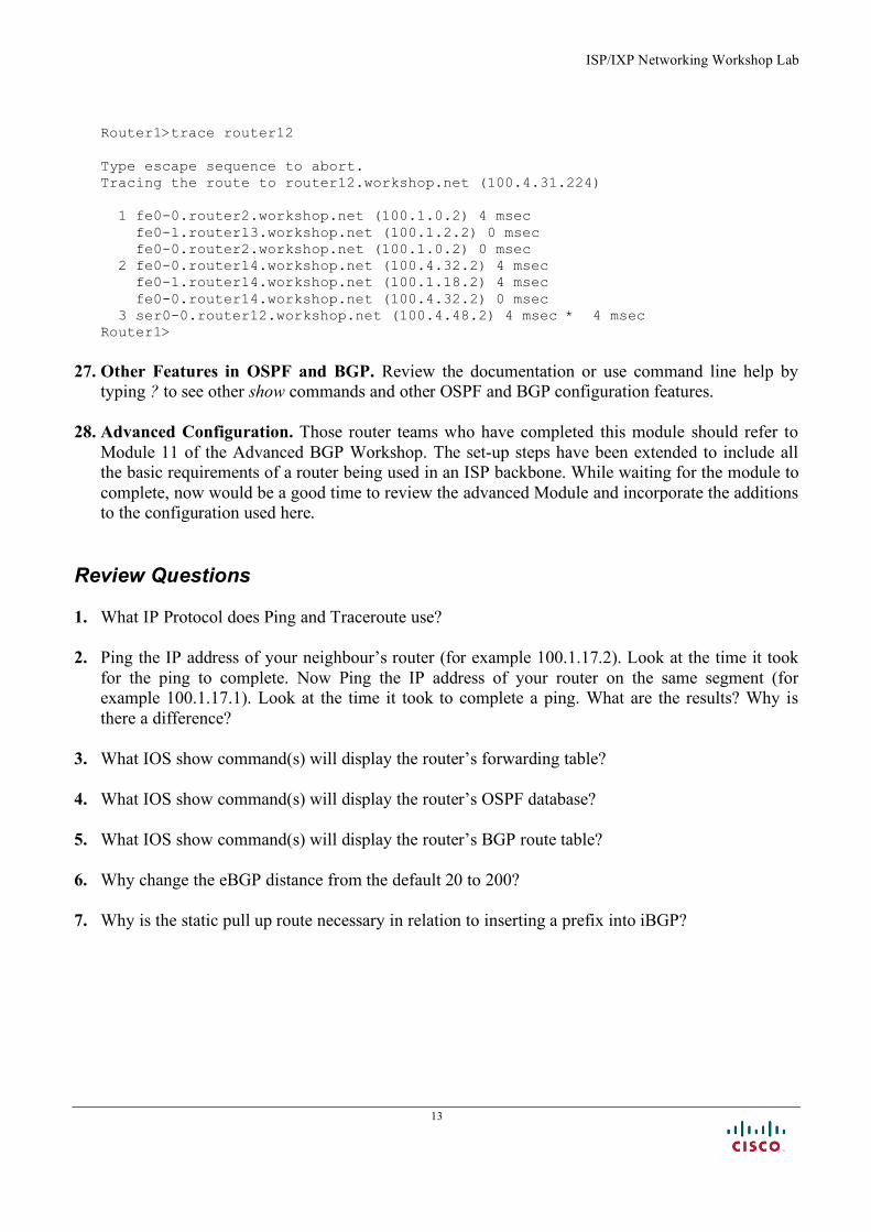
Router1>trace router12 Type escape sequence to abort. Tracing the route to router12.workshop.net (100.4.31.224) 1 fe0-0.router2.workshop.net (100.1.0.2) 4 msec fe0-1.router13.workshop.net (100.1.2.2) 0 msec fe0-0.router2.workshop.net (100.1.0.2) 0 msec 2 fe0-0.router14.workshop.net (100.4.32.2) 4 msec fe0-1.router14.workshop.net (100.1.18.2) 4 msec fe0-0.router14.workshop.net (100.4.32.2) 0 msec 3 ser0-0.router12.workshop.net (100.4.48.2) 4 msec * 4 msec Router1>
27. Other Features in OSPF and BGP. Review the documentation or use command line help by
typing ? to see other show commands and other OSPF and BGP configuration features. 28. Advanced Configuration. Those router teams who have completed this module should refer to
Module 11 of the Advanced BGP Workshop. The set-up steps have been extended to include all the basic requirements of a router being used in an ISP backbone. While waiting for the module to complete, now would be a good time to review the advanced Module and incorporate the additions to the configuration used here.
Review Questions 1. What IP Protocol does Ping and Traceroute use? 2. Ping the IP address of your neighbour’s router (for example 100.1.17.2). Look at the time it took
for the ping to complete. Now Ping the IP address of your router on the same segment (for example 100.1.17.1). Look at the time it took to complete a ping. What are the results? Why is there a difference?
3. What IOS show command(s) will display the router’s forwarding table? 4. What IOS show command(s) will display the router’s OSPF database? 5. What IOS show command(s) will display the router’s BGP route table? 6. Why change the eBGP distance from the default 20 to 200? 7. Why is the static pull up route necessary in relation to inserting a prefix into iBGP?

Monday, July 21, 2008
Cisco Systems Inc 14 170 West Tasman Drive. San Jose, CA 95134-1706 Phone: +1 408 526-4000 Fax: +1 408 536-4100
CONFIGURATION NOTES Documentation is critical! You should record the configuration at each Checkpoint, as well as the configuration at the end of the module.