Embed Size (px)
Citation preview
TS0049UK01
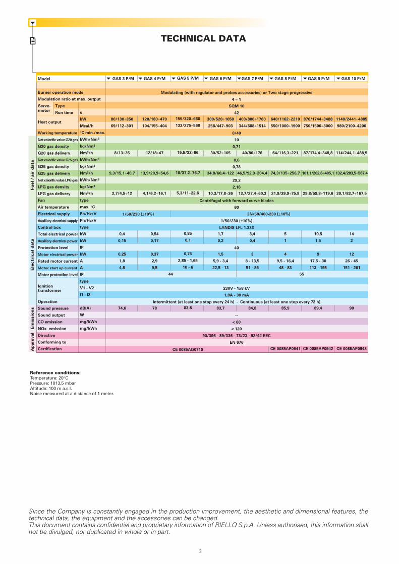
GAS P/M SERIES GAS 3 P/M 80/130 ÷ 350 kWGAS 4 P/M 120/180 ÷ 470 kWGAS 5 P/M 155/320 ÷ 660 kWGAS 6 P/M 300/520 ÷ 1050 kWGAS 7 P/M 400/800 ÷ 1760 kWGAS 8 P/M 640/1162 ÷ 2210 kWGAS 9 P/M 870/1744 ÷ 3488 kWGAS 10 P/M 1140/2441 ÷ 4885 kW
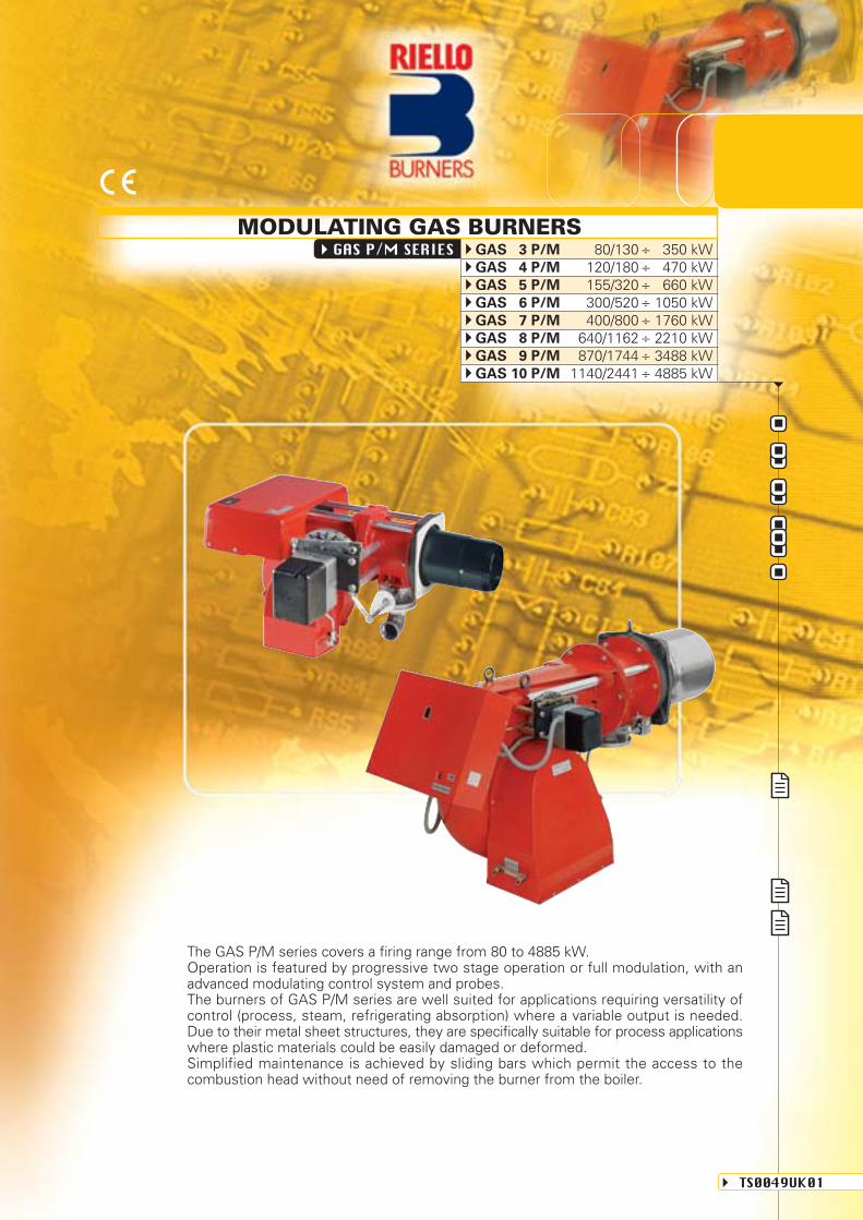
MODULATING GAS BURNERS
The GAS P/M series covers a firing range from 80 to 4885 kW.Operation is featured by progressive two stage operation or full modulation, with anadvanced modulating control system and probes.The burners of GAS P/M series are well suited for applications requiring versatility ofcontrol (process, steam, refrigerating absorption) where a variable output is needed.Due to their metal sheet structures, they are specifically suitable for process applicationswhere plastic materials could be easily damaged or deformed.Simplified maintenance is achieved by sliding bars which permit the access to thecombustion head without need of removing the burner from the boiler.
GAS 4 P/M
120/180÷470
104/155÷404
12/18÷47
13,9/20,9÷54,6
4,1/6,2÷16,1
0,54
0,17
0,37
2,9
9,5
78
CE 0085AQ0710
GAS 3 P/M
80/130÷350
69/112÷301
8/13÷35
9,3/15,1÷40,7
2,7/4,5÷12
0,4
0,15
0,25
1,8
4,8
74,6
TECHNICAL DATAFu
el /
air
dat
aE
lect
rica
l d
ata
Em
issi
on
sA
ppro
val
Model
Burner operation mode
Modulation ratio at max. output
Type
Run time
Working temperature
Net calorific value G20 gas
G20 gas density
G20 gas delivery
Net calorific value G25 gas
G25 gas density
G25 gas delivery
Net calorific value LPG gas
LPG gas density
LPG gas delivery
Fan
Air temperature
Electrical supply
Auxiliary electrical supply
Control box
Total electrical power
Auxiliary electrical power
Protection level
Motor electrical power
Rated motor current
Motor start up current
Motor protection level
Operation
Sound pressure
Sound output
CO emission
NOx emission
Directive
Conforming to
Certification
Servo-motor
s
kW
Mcal/h
°C min./max.
kWh/Nm3
kg/Nm3
Nm3/h
kWh/Nm3
kg/Nm3
Nm3/h
kWh/Nm3
kg/Nm3
Nm3/h
type
max. °C
Ph/Hz/V
Ph/Hz/V
type
kW
kW
IP
kW
A
A
IP
type
V1 - V2
I1 - I2
dB(A)
W
mg/kWh
mg/kWh
Heat output
Ignitiontransformer
3N/50/400-230 (±10%)
44 55
Modulating (with regulator and probes accessories) or Two stage progressive
4 ÷ 1
SQM 10
42
0/40
10
0,71
8,6
0,78
29,2
2,16
Centrifugal with forward curve blades
60
1/50/230 (±10%)
LANDIS LFL 1.333
40
--
230V - 1x8 kV
1,8A - 30 mA
Intermittent (at least one stop every 24 h) - Continuous (at least one stop every 72 h)
--
< 60
< 120
90/396 - 89/336 - 73/23 - 92/42 EEC
EN 676
GAS 10 P/M
1140/2441÷4885
980/2100÷4200
114/244,1÷488,5
132,4/283,5÷567,4
39,1/83,7÷167,5
14
2
12
26 - 45
151 - 261
90
CE 0085AP0943
GAS 5 P/M
155/320÷660
133/275÷568
15,5/32÷66
18/37,2÷76,7
5,3/11÷22,6
0,85
0,1
0,75
2,85 - 1,65
10 - 6
83,8
GAS 6 P/M
300/520÷1050
258/447÷903
30/52÷105
34,8/60,4÷122
10,3/17,8÷36
1,7
0,2
1,5
5,9 - 3,4
22,5 - 13
83,7
GAS 7 P/M
400/800÷1760
344/688÷1514
40/80÷176
46,5/92,9÷204,4
13,7/27,4÷60,3
3,4
0,4
3
8 - 13,5
51 - 86
84,8
GAS 9 P/M
870/1744÷3488
750/1500÷3000
87/174,4÷348,8
101,1/202,6÷405,1
29,8/59,8÷119,6
10,5
1,5
9
17,5 - 30
113 - 195
89,4
CE 0085AP0942
GAS 8 P/M
640/1162÷2210
550/1000÷1900
64/116,3÷221
74,3/135÷256,7
21,9/39,9÷75,8
5
1
4
9,5 - 16,4
48 - 83
85,9
CE 0085AP0941
Since the Company is constantly engaged in the production improvement, the aesthetic and dimensional features, thetechnical data, the equipment and the accessories can be changed.This document contains confidential and proprietary information of RIELLO S.p.A. Unless authorised, this information shallnot be divulged, nor duplicated in whole or in part.
Reference conditions:Temperature: 20°CPressure: 1013,5 mbarAltitude: 100 m a.s.l.Noise measured at a distance of 1 meter.
2
1/50/230 (±10%)
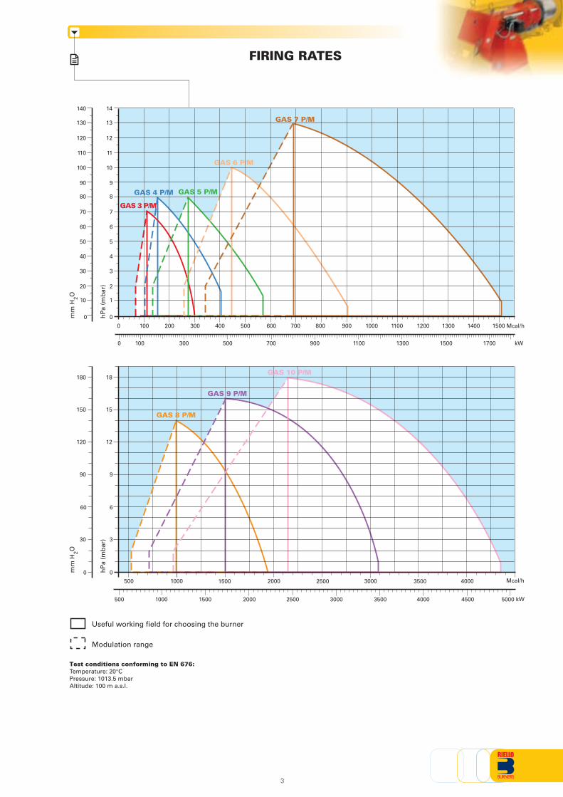
FIRING RATES
Useful working field for choosing the burner
Modulation range
Test conditions conforming to EN 676:Temperature: 20°CPressure: 1013.5 mbarAltitude: 100 m a.s.l.
100 400 700 800 1000 1300200 300 500 600 900 1100 1200 14000 1500
1000 2000 3000 40001500 2500 3500500
hP
a (m
bar
)
mm
H2O
hP
a (m
bar
)
mm
H2O
3
0
14
5
4
3
2
1
6
7
8
9
10
11
12
13
GAS 3 P/M
GAS 4 P/M GAS 5 P/M
GAS 6 P/M
GAS 7 P/M
140
50
40
30
20
10
60
70
80
90
100
110
120
130
0
kW100 300 500 700 900 1100 1300 1500 17000
Mcal/h
0
18
15
12
9
6
3
GAS 8 P/M
GAS 9 P/M
GAS 10 P/M180
150
120
90
60
30
0Mcal/h
kW400030001000 2000 50001500 2500 3500 4500500
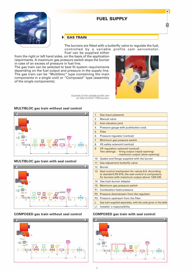
The burners are fitted with a butterfly valve to regulate the fuel,controlled by a variable profile cam servomotor.Fuel can be supplied either
from the right or left hand sides, on the basis of the applicationrequirments. A maximum gas pressure switch stops the burnerin case of an excess of pressure in fuel line.The gas train can be selected to best fit system requirementsdepending on the fuel output and pressure in the supply line.The gas train can be “Multibloc“ type (containing the maincomponents in a single unit) or “Composed” type (assemblyof the single components).
1
2
3
4
5
6
7
8
9
10
11
12
13
14
15
P1
P2
P3
L
L1
L L
MULTIBLOC
9 8
L L
MULTIBLOC
GAS TRAIN
FUEL SUPPLY
Example of the variable profile camon GAS 3-4-5-6-7 P/M burners.
MULTIBLOC gas train without seal control
MULTIBLOC gas train with seal control
COMPOSED gas train without seal control COMPOSED gas train with seal control
12
P1
11
1015
14 9 8 P2 6 P3
4
3 2 15
P1
11
1015
14 P3
4
3 2 113
12
56P2
7
7
1212
Gas input pipework
Manual valve
Anti-vibration joint
Pressure gauge with pushbutton cock.
Filter
Pressure regulator (vertical)
Minimum gas pressure switch
VS safety solenoid (vertical)
VR regulation solenoid (vertical)Two settings: - firing output (rapid opening)
- maximum output (slow opening)
Gasket and flange supplied with the burner
Gas adjustment butterfly valve
Burner
Seal control mechanism for valves 8-9. Accordingto standard EN 676, the seal control is compulsoryfor burners with maximum output above 1200 kW.
Gas train-burner adapter.
Maximum gas pressure switch
Combustion head pressure
Pressure downstream from the regulator
Pressure upstream from the filter
Gas train supplied separately, with the code given in the table
Installer’ s responsibility
4
L L1
P1
15 1110
14 6
L L1
9 8
7
5
4
P3P2
3 2 1
P1
1511
10
14 9 6 8
7
5
4
P3P2
3 2 1
CO
MP
OS
ED
GA
S T
RA
INS
MU
LTIB
LOC
GA
S T
RA
INS
Name
MBD 407
MBD 410
MBD 412
MBD 412 CT
MBD 415
MBD 415 CT
MBD 420
MBD 420 CT
MBC 1200 SE 50
MBC 1200 SE 50 CT
MBC 1900 SE 65 FC
MBC 1900 SE 65 FC CT
MBC 3100 SE 80 FC
MBC 3100 SE 80 FC CT
MBC 5000 SE 100 FC
MBC 5000 SE 100 FC CT
Code
3970553
3970554
3970144
3970197
3970180
3970198
3970181
3970182
3970221
3970225
3970222
3970226
3970223
3970227
3970224
3970228
Ø i
3/4”
1”
1”1/4
1”1/4
1”1/2
1”1/2
2”
2”
2”
2”
DN 65
DN 65
DN 80
DN 80
DN 100
DN 100
Ø o
3/4”
3/4”
1”1/2
1”1/2
1”1/2
1”1/2
2”
2”
2”
2”
DN 65
DN 65
DN 80
DN 80
DN 100
DN 100
X mm
371
405
433
433
523
523
523
523
573
573
583
583
633
633
733
733
Z mm
196
217
217
217
250
250
300
300
161
290
237
300
240
320
576
576
Y mm
120
145
145
262
100
227
100
227
425
426
430
430
500
500
350
350
Seal Control
accessory
accessory
accessory
incorporated
accessory
incorporated
accessory
incorporated
accessory
incorporated
accessory
incorporated
accessory
incorporated
accessory
incorporated
Y
Z X
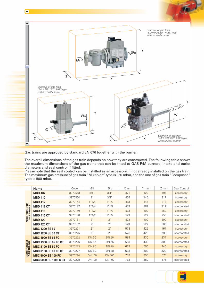
Gas trains are approved by standard EN 676 together with the burner.
The overall dimensions of the gas train depends on how they are constructed. The following table showsthe maximum dimensions of the gas trains that can be fitted to GAS P/M burners, intake and outletdiameters and seal control if fitted.Please note that the seal control can be installed as an accessory, if not already installed on the gas train.The maximum gas pressure of gas train “Multibloc” type is 360 mbar, and the one of gas train “Composed”type is 500 mbar.
Example of gas train“MULTIBLOC” MBD typewithout seal control
Example of gas train“COMPOSED” MBC typewithout seal control
Y
ZX
Øo
Øi
Øi
Øo
Example of gas train“MULTIBLOC” MBC typewithout seal control
5
Y
Z X
W
Øi
Øo
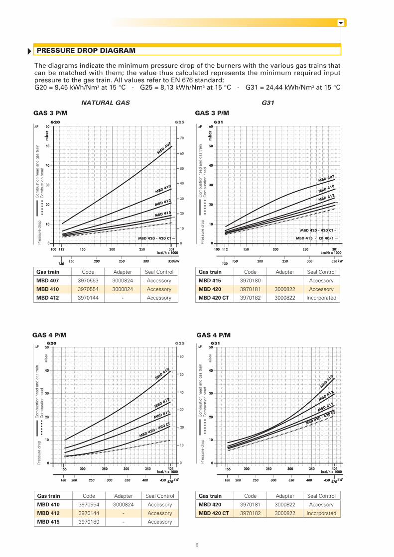
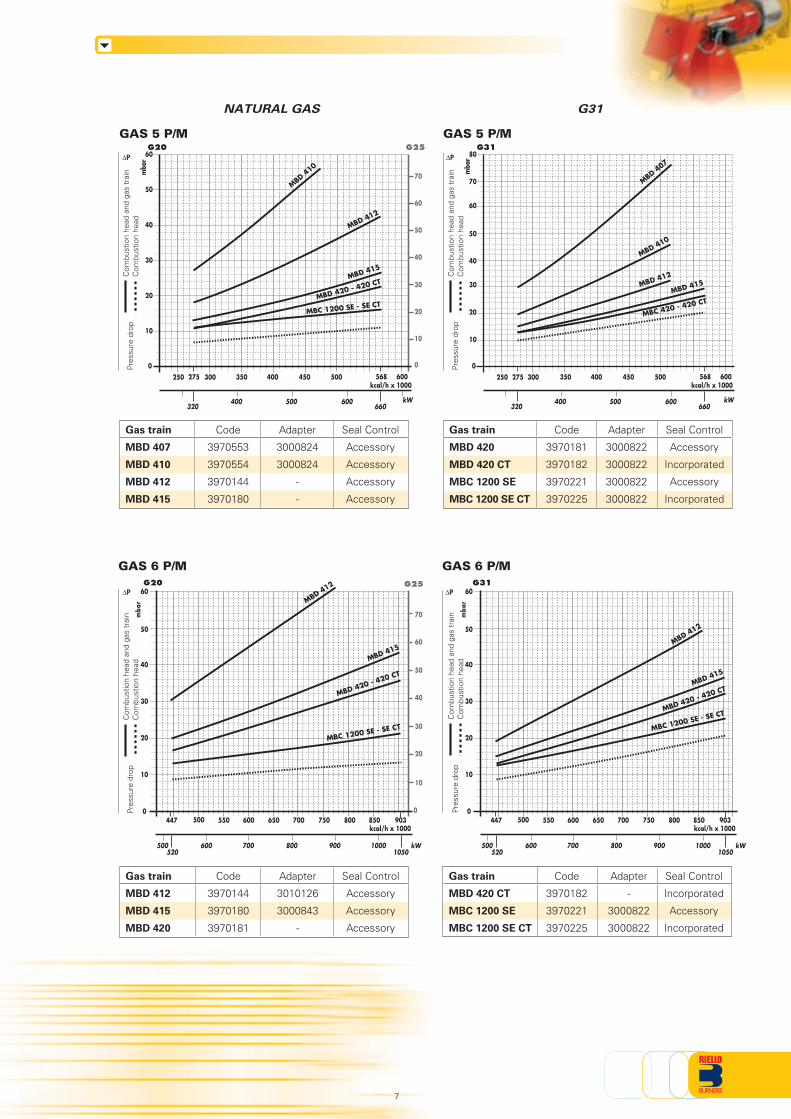
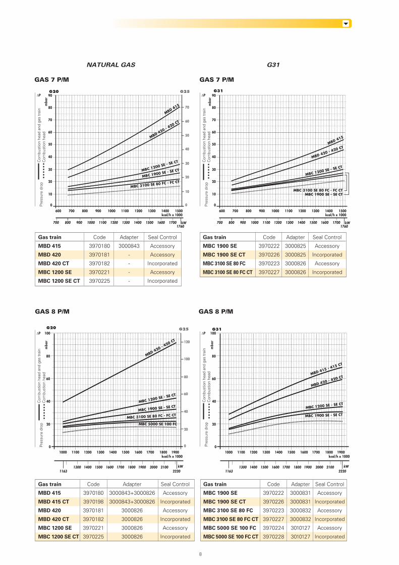
The diagrams indicate the minimum pressure drop of the burners with the various gas trains thatcan be matched with them; the value thus calculated represents the minimum required inputpressure to the gas train. All values refer to EN 676 standard:G20 = 9,45 kWh/Nm3 at 15 °C - G25 = 8,13 kWh/Nm3 at 15 °C - G31 = 24,44 kWh/Nm3 at 15 °C
PRESSURE DROP DIAGRAM
NATURAL GAS G31
Gas train
MBD 415
MBD 420
MBD 420 CT
Code
3970180
3970181
3970182
Adapter
-
3000822
3000822
Seal Control
Accessory
Accessory
Incorporated
Gas train
MBD 407
MBD 410
MBD 412
Code
3970553
3970554
3970144
Adapter
3000824
3000824
-
Seal Control
Accessory
Accessory
Accessory
Gas train
MBD 410
MBD 412
MBD 415
Code
3970554
3970144
3970180
Seal Control
Accessory
Accessory
Accessory
Gas train
MBD 420
MBD 420 CT
Code
3970181
3970182
Adapter
3000822
3000822
Seal Control
Accessory
Incorporated
Adapter
3000824
-
-
MBD 420 - 420 CT
GAS 3 P/M
100 150 250 301200112kcal/h x 1000
kW150130
200 250 300 350
mba
r
10
20
30
40
50
0
G20 G25
0
10
20
50
40
30
60MBD 407
MBD 410
MBD 412
MBD 415
GAS 3 P/M
60
70
ΔP
Com
bust
ion
head
and
gas
tra
inC
ombu
stio
n he
adPr
essu
re d
rop
Com
bust
ion
head
and
gas
tra
inC
ombu
stio
n he
adPr
essu
re d
rop
10
20
30
40
50
kW
kcal/h x 1000350250 300200 404155
250200 350 400 450 470300180
0
mba
r
G20 G25
GAS 4 P/M
MBD 410
MBD 412
MBD 415
MBD 420 - 420 CT
Com
bust
ion
head
and
gas
tra
inC
ombu
stio
n he
adPr
essu
re d
rop
0
10
20
50
40
30
60
Com
bust
ion
head
and
gas
tra
inC
ombu
stio
n he
adPr
essu
re d
rop
GAS 4 P/M
MBD 420 - 420 CT
100 150 250 301200112kcal/h x 1000
kW150 200 250 300 350
mba
r
10
20
30
40
50
0
G31
MBD 407
MBD 410
MBD 412
MBD 415 - CB 40/1
60
10
20
30
40
50
kW
kcal/h x 1000350250 300200 404155
250200 350 400 450 470300180
0
mba
r
G31
MBD
410
MBD 412
MBD 415
MBD 420 - 420 CT
ΔP
ΔP ΔP
130
6
NATURAL GAS G31
Gas train
MBD 407
MBD 410
MBD 412
MBD 415
Code
3970553
3970554
3970144
3970180
Adapter
3000824
3000824
-
-
Seal Control
Accessory
Accessory
Accessory
Accessory
Gas train
MBD 412
MBD 415
MBD 420
Code
3970144
3970180
3970181
Adapter
3010126
3000843
-
Seal Control
Accessory
Accessory
Accessory
Gas train
MBD 420
MBD 420 CT
MBC 1200 SE
MBC 1200 SE CT
Code
3970181
3970182
3970221
3970225
Adapter
3000822
3000822
3000822
3000822
Seal Control
Accessory
Incorporated
Accessory
Incorporated
Gas train
MBD 420 CT
MBC 1200 SE
MBC 1200 SE CT
Code
3970182
3970221
3970225
Seal Control
Incorporated
Accessory
Incorporated
Adapter
-
3000822
3000822
GAS 5 P/M
kcal/h x 1000
10
20
30
40
50
447 550 600500 800700 750650 850 903
mba
r
1000600 700 800 900500 kW
0 0
10
20
50
40
30
60
G20 G25
GAS 6 P/M
MBD 412
MBD 415
MBD 420 - 420 CT
10
20
30
40
50
kW
kcal/h x 1000350 400300 600500450 568275
400 500660320
600
250
0
mba
r
0
10
20
50
40
30
60
G20 G25
MBD 412
MBD 415
MBD 420 - 420 CT
60
70MBD 4
10
60
70
GAS 6 P/M
10
20
30
40
50
kW
kcal/h x 1000350 400300 600500450 568275
400 500660320
600
250
0
mba
r
G31
60
MBD 412
MBD 415
MBC 420 - 420 CT
MBD 410
mba
r
G31
GAS 5 P/M
ΔP ΔP
ΔP ΔP
MBC 1200 SE - SE CT
70
80
MBD 407
1050520
MBC 1200 SE - SE CT
kcal/h x 1000
10
20
30
40
50
447 550 600500 800700 750650 850 903
1000600 700 800 900500 kW
0
MBD 415
MBD 420 - 420 CT
60
1050520
MBC 1200 SE - SE CT
MBD 412
7
Com
bust
ion
head
and
gas
tra
inC
ombu
stio
n he
adPr
essu
re d
rop
Com
bust
ion
head
and
gas
tra
inC
ombu
stio
n he
adPr
essu
re d
rop
Com
bust
ion
head
and
gas
tra
inC
ombu
stio
n he
adPr
essu
re d
rop
Com
bust
ion
head
and
gas
tra
inC
ombu
stio
n he
adPr
essu
re d
rop
NATURAL GAS G31
Gas train
MBC 1900 SE
MBC 1900 SE CT
MBC 3100 SE 80 FC
MBC 3100 SE 80 FC CT
Code
3970222
3970226
3970223
3970227
Adapter
3000825
3000825
3000826
3000826
Seal Control
Accessory
Incorporated
Accessory
Incorporated
Gas train
MBD 415
MBD 415 CT
MBD 420
MBD 420 CT
MBC 1200 SE
MBC 1200 SE CT
Code
3970180
3970198
3970181
3970182
3970221
3970225
Adapter
3000843+3000826
3000843+3000826
3000826
3000826
3000826
3000826
Seal Control
Accessory
Incorporated
Accessory
Incorporated
Accessory
Incorporated
Gas train
MBC 1900 SE
MBC 1900 SE CT
MBC 3100 SE 80 FC
MBC 3100 SE 80 FC CT
MBC 5000 SE 100 FC
MBC 5000 SE 100 FC CT
Code
3970222
3970226
3970223
3970227
3970224
3970228
Adapter
3000831
3000831
3000832
3000832
3010127
3010127
Seal Control
Accessory
Incorporated
Accessory
Incorporated
Accessory
Incorporated
Gas train
MBD 415
MBD 420
MBD 420 CT
MBC 1200 SE
MBC 1200 SE CT
Code
3970180
3970181
3970182
3970221
3970225
Adapter
3000843
-
-
-
-
Seal Control
Accessory
Accessory
Incorporated
Accessory
Incorporated
Com
bust
ion
head
and
gas
tra
inC
ombu
stio
n he
adPr
essu
re d
rop
Com
bust
ion
head
and
gas
tra
inC
ombu
stio
n he
adPr
essu
re d
rop
Com
bust
ion
head
and
gas
tra
inC
ombu
stio
n he
adPr
essu
re d
rop
Com
bust
ion
head
and
gas
tra
inC
ombu
stio
n he
adPr
essu
re d
rop
G20
GAS 7 P/M
G25
0
10
20
50
40
30
60
70
mba
r
kcal/h x 1000
20
40
60
80
kW16001300 1400 1500 20001700 1800 19002220
21001163
1000 1200 13001100 17001500 16001400 1800 1900
100
0
G20 G25
0
20
40
100
80
60
120
GAS 8 P/M
GAS 7 P/M
GAS 8 P/M
10
20
30
40
50
kW1100
kcal/h x 1000
800 900 1000 1200 1300 1400 1500 1600 17001760
600 800 900700 13001100 12001000 1400 1500m
bar
G31
700
60
mba
r
kcal/h x 1000
20
40
60
80
kW16001300 1400 1500 20001700 1800 19002220
21001163
1000 1200 13001100 17001500 16001400 1800 1900
100
0
G31
70
80
90
0
MBD 420 - 420 CTMBD 415
ΔP ΔP
ΔP ΔP
1760
10
20
30
40
50
kW1100
kcal/h x 1000
800 900 1000 1200 1300 1400 1500 1600 1700
600 800 900700 13001100 12001000 1400 1500
mba
r
700
60
70
80
90
0
MBD 420 - 420 CT
MBD 415
MBC 1200 SE - SE CT
MBC 1900 SE - SE CT
MBC 3100 SE 80 FC - FC CT
MBC 1200 SE - SE CT
MBC 1900 SE - SE CTMBC 3100 SE 80 FC - FC CT
MBD 420 - 420 CT
MBC 1200 SE - SE CT
MBC 1900 SE - SE CT
MBC 3100 SE 80 FC - FC CT
MBC 5000 SE 100 FC
MBD 415 - 415 CT
MBD 420 - 420 CT
MBC 1200 SE - SE CT
MBC 1900 SE - SE CT
8
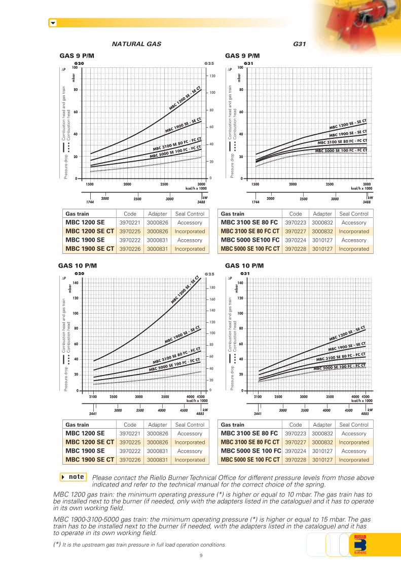
Please contact the Riello Burner Technical Office for different pressure levels from those aboveindicated and refer to the technical manual for the correct choice of the spring.
note
NATURAL GAS G31
MBC 1200 gas train: the minimum operating pressure (*) is higher or equal to 10 mbar. The gas train has tobe installed next to the burner (if needed, only with the adapters listed in the catalogue) and it has to operatein its own working field.
MBC 1900-3100-5000 gas train: the minimum operating pressure (*) is higher or equal to 15 mbar. The gastrain has to be installed next to the burner (if needed, with the adapters listed in the catalogue) and it hasto operate in its own working field.
(*) It is the upstream gas train pressure in full load operation conditions.
Gas train
MBC 1200 SE
MBC 1200 SE CT
MBC 1900 SE
MBC 1900 SE CT
Code
3970221
3970225
3970222
3970226
Adapter
3000826
3000826
3000831
3000831
Seal Control
Accessory
Incorporated
Accessory
Incorporated
Gas train
MBC 3100 SE 80 FC
MBC 3100 SE 80 FC CT
MBC 5000 SE100 FC
MBC 5000 SE 100 FC CT
Code
3970223
3970227
3970224
3970228
Adapter
3000832
3000832
3010127
3010127
Seal Control
Accessory
Incorporated
Accessory
Incorporated
Gas train
MBC 1200 SE
MBC 1200 SE CT
MBC 1900 SE
MBC 1900 SE CT
Code
3970221
3970225
3970222
3970226
Adapter
3000826
3000826
3000831
3000831
Seal Control
Accessory
Incorporated
Accessory
Incorporated
Gas train
MBC 3100 SE 80 FC
MBC 3100 SE 80 FC CT
MBC 5000 SE 100 FC
MBC 5000 SE 100 FC CT
Code
3970223
3970227
3970224
3970228
Adapter
3000832
3000832
3010127
3010127
Seal Control
Accessory
Incorporated
Accessory
Incorporated
Com
bust
ion
head
and
gas
tra
inC
ombu
stio
n he
adPr
essu
re d
rop
Com
bust
ion
head
and
gas
tra
inC
ombu
stio
n he
adPr
essu
re d
rop
mba
r
kcal/h x 1000
20
40
60
80
kW2441
2100 2500 3000 42003500 4000
48853000 3500 4000 4500
0
100
G20 G25
0
20
40
100
80
60
120
GAS 9 P/M
25001500 2000 3000
mba
r
20
40
60
80
kW
kcal/h x 1000
17442000 2500 3000
3488
100
0
G20 G25
0
20
40
100
80
60
120
Com
bust
ion
head
and
gas
tra
inC
ombu
stio
n he
adPr
essu
re d
rop
Com
bust
ion
head
and
gas
tra
inC
ombu
stio
n he
adPr
essu
re d
rop
GAS 9 P/M
25001500 2000 3000
mba
r
20
40
60
80
kW
kcal/h x 1000
17442000 2500 3000
3488
100
0
G31
G31
MBC 1200 SE - S
E CT
MBC 1900 SE - SE CT
MBC 3100 SE 80 FC - FC CT
MBC 5000 SE 100 FC - FC CT
ΔP ΔP
MBC 1200 SE - SE CT
MBC 3100 SE 80 FC - FC CTMBC 1900 SE - SE CT
MBC 5000 SE 100 FC - FC CT
ΔP ΔP
120
140
140
160
180
MBC
120
0 SE
- SE
CT
MBC 1900 SE - SE CT
MBC 3100 SE 80 FC - FC CT
MBC 5000 SE 100 FC - FC CT
mba
r
kcal/h x 1000
20
40
60
80
kW2441
2100 2500 3000 42003500 4000
48853000 3500 4000 4500
0
100
120
140
MBC 1200 SE - SE CT
MBC 1900 SE - SE CT
MBC 3100 SE 80 FC - FC CT
MBC 5000 SE 100 FC - FC CT
GAS 10 P/M GAS 10 P/M
9
SELECTING THE FUEL SUPPLY LINES
0,1 0,2 0,3 0,4 0,5 0,6 0,7 0,8 1 2 3 4 5 106 20
50 60 10080 200 400 800 1000600
3
69
12152230
45 61 76 95 122 152 V
PRESSURE DROP (mbar)
1 2 3 4 5 6 7 8 10 20 30 40
PIPE DIAMETER
1,4
PIPE LENGTH (m)
1/2
3/4
1"
1" 1/2
6"
1" 1/4
4"
3"2" 1/22"
= Gas output Nmc/h
1 - G20= 0,62 - G25
1,18 - G31{
V
15,34
10
Figure A
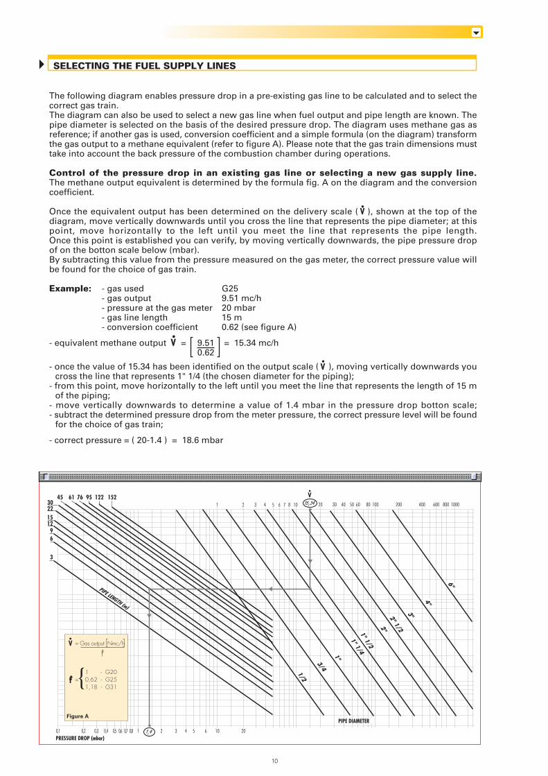
The following diagram enables pressure drop in a pre-existing gas line to be calculated and to select thecorrect gas train.The diagram can also be used to select a new gas line when fuel output and pipe length are known. Thepipe diameter is selected on the basis of the desired pressure drop. The diagram uses methane gas asreference; if another gas is used, conversion coefficient and a simple formula (on the diagram) transformthe gas output to a methane equivalent (refer to figure A). Please note that the gas train dimensions musttake into account the back pressure of the combustion chamber during operations.
Control of the pressure drop in an existing gas line or selecting a new gas supply line.The methane output equivalent is determined by the formula fig. A on the diagram and the conversioncoefficient.
Once the equivalent output has been determined on the delivery scale ( ), shown at the top of thediagram, move vertically downwards until you cross the line that represents the pipe diameter; at thispoint, move horizontally to the left until you meet the line that represents the pipe length.Once this point is established you can verify, by moving vertically downwards, the pipe pressure dropof on the botton scale below (mbar).By subtracting this value from the pressure measured on the gas meter, the correct pressure value willbe found for the choice of gas train.
Example: - gas used G25- gas output 9.51 mc/h- pressure at the gas meter 20 mbar- gas line length 15 m- conversion coefficient 0.62 (see figure A)
- equivalent methane output = 9.51 = 15.34 mc/h0.62
- once the value of 15.34 has been identified on the output scale ( ), moving vertically downwards youcross the line that represents 1" 1/4 (the chosen diameter for the piping);
- from this point, move horizontally to the left until you meet the line that represents the length of 15 mof the piping;
- move vertically downwards to determine a value of 1.4 mbar in the pressure drop botton scale;- subtract the determined pressure drop from the meter pressure, the correct pressure level will be found
for the choice of gas train;
- correct pressure = ( 20-1.4 ) = 18.6 mbar
V
V
V
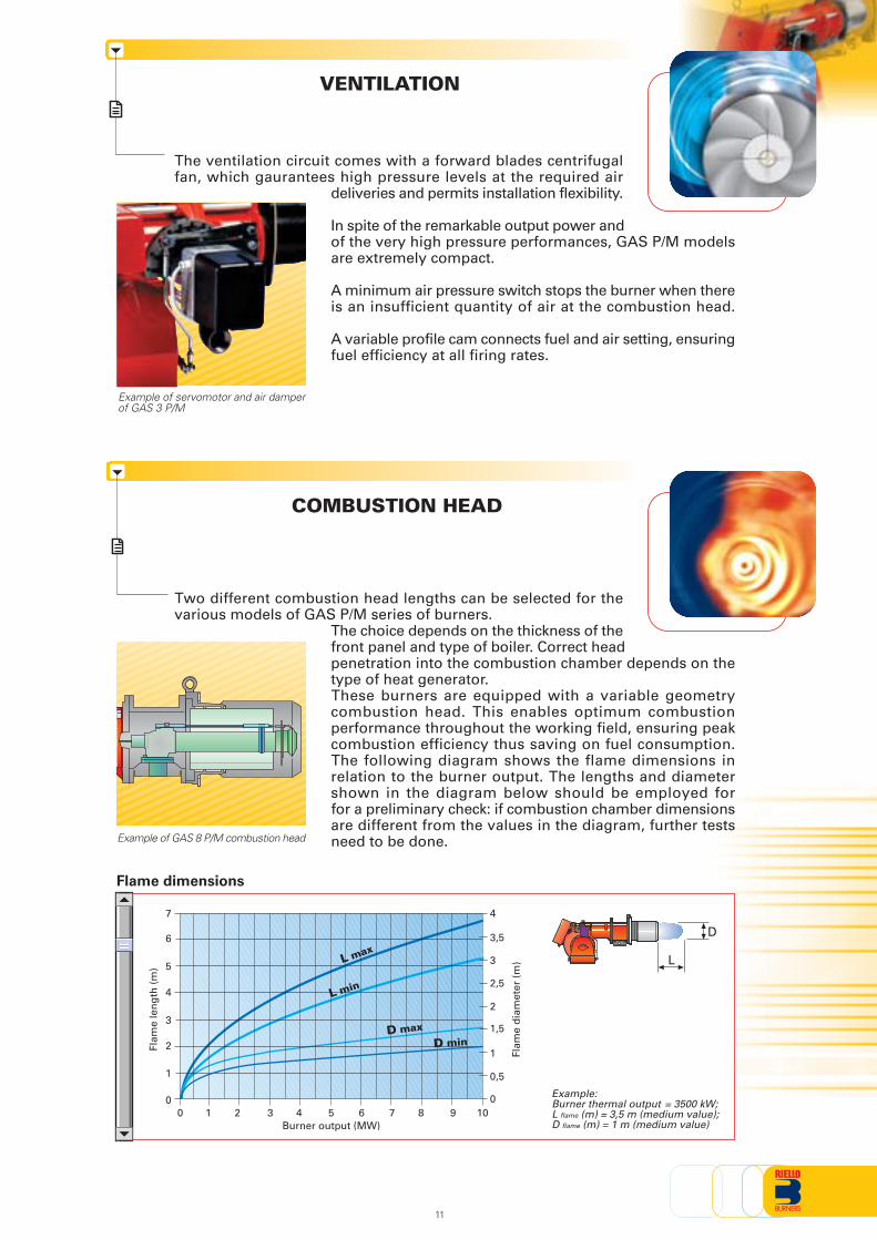
The ventilation circuit comes with a forward blades centrifugalfan, which gaurantees high pressure levels at the required air
deliveries and permits installation flexibility.
In spite of the remarkable output power andof the very high pressure performances, GAS P/M modelsare extremely compact.
A minimum air pressure switch stops the burner when thereis an insufficient quantity of air at the combustion head.
A variable profile cam connects fuel and air setting, ensuringfuel efficiency at all firing rates.
COMBUSTION HEAD
VENTILATION
Example of servomotor and air damperof GAS 3 P/M
Two different combustion head lengths can be selected for thevarious models of GAS P/M series of burners.
The choice depends on the thickness of thefront panel and type of boiler. Correct headpenetration into the combustion chamber depends on thetype of heat generator.These burners are equipped with a variable geometrycombustion head. This enables optimum combustionperformance throughout the working field, ensuring peakcombustion efficiency thus saving on fuel consumption.The following diagram shows the flame dimensions inrelation to the burner output. The lengths and diametershown in the diagram below should be employed forfor a preliminary check: if combustion chamber dimensionsare different from the values in the diagram, further testsneed to be done.
Flame dimensions
Example of GAS 8 P/M combustion head
Example:Burner thermal output = 3500 kW;L flame (m) = 3,5 m (medium value);D flame (m) = 1 m (medium value)Burner output (MW)
0 2
3
5
1
1 3
2
4
6
7
4 5 6 7 8 9 10
Flam
e le
ng
th (
m)
Flam
e d
iam
eter
(m
)
0
4
0
0,5
1
1,5
2
2,5
3
3,5 D
LL max
L min
D max
D min
11
time (s)0
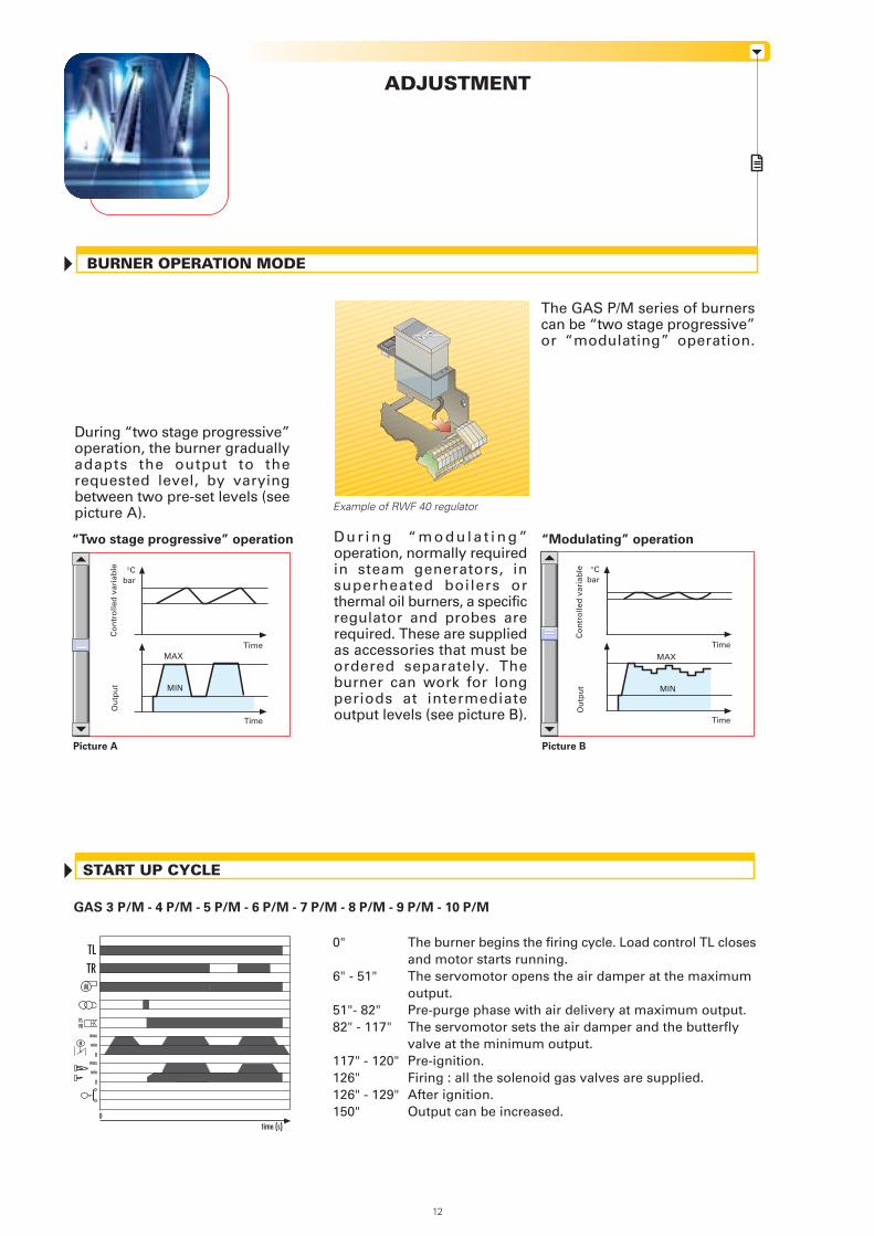
GAS 3 P/M - 4 P/M - 5 P/M - 6 P/M - 7 P/M - 8 P/M - 9 P/M - 10 P/M
START UP CYCLE
ADJUSTMENT
BURNER OPERATION MODE
The GAS P/M series of burnerscan be “two stage progressive”or “modulating” operation.
D u r i n g “ m o d u l a t i n g ”operation, normally requiredin steam generators, insuperheated boilers orthermal oil burners, a specificregulator and probes arerequired. These are suppliedas accessories that must beordered separately. Theburner can work for longperiods at intermediateoutput levels (see picture B).
During “two stage progressive”operation, the burner graduallyadapts the output to therequested level, by varyingbetween two pre-set levels (seepicture A).
Picture BPicture A
bar°C
MAX
MIN
Time
Time
Example of RWF 40 regulator
Ou
tpu
tC
on
tro
lled
var
iab
le
Ou
tpu
tC
on
tro
lled
var
iab
le
0" The burner begins the firing cycle. Load control TL closesand motor starts running.
6" - 51" The servomotor opens the air damper at the maximum output.
51"- 82" Pre-purge phase with air delivery at maximum output.82" - 117" The servomotor sets the air damper and the butterfly
valve at the minimum output.117" - 120" Pre-ignition.126" Firing : all the solenoid gas valves are supplied.126" - 129" After ignition.150" Output can be increased.
“Two stage progressive” operation
bar°C
MAX
MIN
Time
Time
“Modulating” operation
TL
max
min
0
0
M
M
TR
VSVR
max
min
12
ϑ P P
P P
“TWO STAGE PROGRESSIVE” OPERATION
WIRING DIAGRAMS
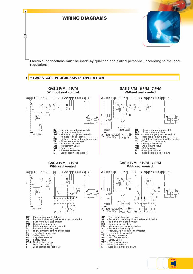
Electrical connections must be made by qualified and skilled personnel, according to the localregulations.
GAS 3 P/M - 4 P/MWithout seal control
GAS 5 P/M - 6 P/M - 7 P/MWithout seal control
IN - Burner manual stop switchMB - Burner terminal stripPG - Minimum gas pressure switchS - Remote lock-out signalTR - High/low flame setting thermostatTL - Threshold thermostatTS - Safety thermostatVR - Adjustment valveVS - Safety valveF - Fuse (see table A)L - Lead section (see table A)
GAS 5 P/M - 6 P/M - 7 P/MWith seal control
XP - Plug for seal control deviceS1 - Remote lock-out signal for seal control deviceIN - Burner manual stop switchMB - Burner terminal stripPG - Minimum gas pressure switchS - Remote lock-out signalTR - High/low flame setting thermostatTL - Threshold thermostatTS - Safety thermostatVR - Adjustment valveVS - Safety valveVPS - Seal control deviceF - Fuse (see table A)L - Lead section (see table A)
GAS 3 P/M - 4 P/MWith seal control
IN - Burner manual stop switchMB - Burner terminal stripPG - Minimum gas pressure switchS - Remote lock-out signalTR - High/low flame setting thermostatTL - Threshold thermostatTS - Safety thermostatVR - Adjustment valveVS - Safety valveF - Fuse (see table A)L - Lead section (see table A)
ϑ P
P
XP - Plug for seal control deviceS1 - Remote lock-out signal for seal control deviceIN - Burner manual stop switchMB - Burner terminal stripPG - Minimum gas pressure switchS - Remote lock-out signalTR - High/low flame setting thermostatTL - Threshold thermostatTS - Safety thermostatVR - Adjustment valveVS - Safety valveVPS - Seal control deviceF - Fuse (see table A)L - Lead section (see table A)
P
NLMB 1 2
PE L N
F
STL
IN
3 4 N N5 L
TS
PG
M B1Y2 Y1W1W2 Q VG
TRN V
VR VS
NLMB 1 2
PE L N
F
STL
IN
3 4 N N5 L
TS
M B1Y2 Y1W1W2 Q VGN V
VR VS
T8 T6
S1
NT8 T6T7 L1
PG
XP
VPS
B5
L1 L2 L3 N LMB 1 2
L
PE L1 L2 L3
T6A
N L
TS STL
IN
~50Hz 230V
3
F
~M3
4 5 N NL M B1Y2 Y1W1W2 Q VG
TRN V
VR VS
T8 T6
S1
NT8 T6T7 L1
PG
XP
VPS
B5
ϑ P
ϑ P
ϑ P
~50Hz 230V3~3N 50Hz 400/230V
ϑ Pϑ P ϑ P
~50Hz 230V
~50Hz 230V
13
LP
P P
L1 L2 L3 N LMB 1 2
L
PE L1 L2 L3
T6A
N L
TS STL
IN
~50Hz 230V
3
F
~M3
4 5
PG
N NL M B1Y2 Y1W1W2 Q VG
TRN V
VR VS
~50Hz 230V3~3N 50Hz 400/230V
ϑ Pϑ P ϑ P
L
TRϑ P
GAS 8 P/M - 9 P/MWith seal control - Direct start-up version
GAS 9 P/M - 10 P/MWith seal control - Star-delta start-up version
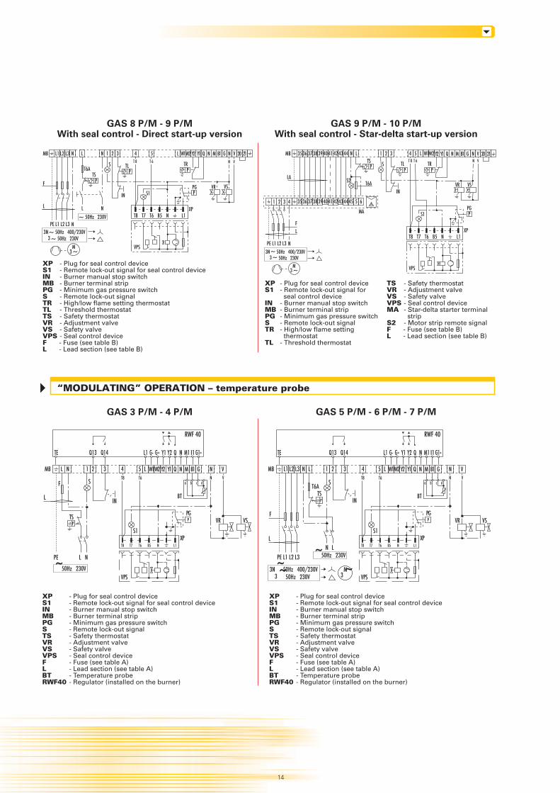
XP - Plug for seal control deviceS1 - Remote lock-out signal for seal control deviceIN - Burner manual stop switchMB - Burner terminal stripPG - Minimum gas pressure switchS - Remote lock-out signalTR - High/low flame setting thermostatTL - Threshold thermostatTS - Safety thermostatVR - Adjustment valveVS - Safety valveVPS - Seal control deviceF - Fuse (see table B)L - Lead section (see table B)
XP - Plug for seal control deviceS1 - Remote lock-out signal for
seal control deviceIN - Burner manual stop switchMB - Burner terminal stripPG - Minimum gas pressure switchS - Remote lock-out signalTR - High/low flame setting
thermostatTL - Threshold thermostat
TS - Safety thermostatVR - Adjustment valveVS - Safety valveVPS - Seal control deviceMA - Star-delta starter terminal
stripS2 - Motor strip remote signalF - Fuse (see table B)L - Lead section (see table B)
XP - Plug for seal control deviceS1 - Remote lock-out signal for seal control deviceIN - Burner manual stop switchMB - Burner terminal stripPG - Minimum gas pressure switchS - Remote lock-out signalTS - Safety thermostatVR - Adjustment valveVS - Safety valveVPS - Seal control deviceF - Fuse (see table A)L - Lead section (see table A)BT - Temperature probeRWF40 - Regulator (installed on the burner)
XP - Plug for seal control deviceS1 - Remote lock-out signal for seal control deviceIN - Burner manual stop switchMB - Burner terminal stripPG - Minimum gas pressure switchS - Remote lock-out signalTS - Safety thermostatVR - Adjustment valveVS - Safety valveVPS - Seal control deviceF - Fuse (see table A)L - Lead section (see table A)BT - Temperature probeRWF40 - Regulator (installed on the burner)
P
GAS 3 P/M - 4 P/M GAS 5 P/M - 6 P/M - 7 P/M
P
VR VS
~M3
~ 50Hz 230V33N 50Hz 400/230V~
L1 L2 L3 N LMB 1 2
L
PE L1 L2 L3
T6A
N L
TS
S
IN
~50Hz 230V
3
F
~M3
4 5 N NL M B1Y2 Y1W1W2 Q VGN V
VR VS
T8 T6
S1
NT8 T6T7 L1
PG
XP
VPS
B5
NLMB 1 2
PE L N
F S
IN
3 4 N5 L
TS
M B1Y2 Y1W1W2 Q GT8 T6
S1
NT8 T6T7 L1
PG
XP
VPS
B5
~50Hz 230V3~3N 50Hz 400/230V
ϑ P
Q13 Q14 QG- NL1 G+ G1+
ϑ P
Q13 Q14 QG- NL1 G+ G1+
RWF 40
Y2Y1 M1 I1TE
~50Hz 230V
RWF 40
Y2Y1 M1 I1TE
3536 3738 LMB 1 2 3 4 5 L
FL
PE L1 L2 L3
T6A
TS S TR
N
PP P
Y2 Y1 Q N M B1 G
TL
1 2 3 4 35 36 3738 39 40 41 42 43 44 45 5 6
39 40 41 42 43 44
S2
MA
LA
N
IN
T 8 T 6
T8
S1
T7 T6 B5 N L1XP
PPG
VPS
N V 20 21N V
W2W1
14
VR VS
~M3
~ 50Hz 230V3~3N 50Hz 400/230V
L1 L2 L3 N LMB 1 2 3 4 5
F
L
PE L1 L2 L3
T6A
NL
TS
S
~ 50Hz 230V
N
N
P
P
P
Y2 Y1 Q N M B1 G
TL
IN
T8
S1
T7 T6 B5 N L1XP
PPG
VPS
L N V 20 21N V
W1W2T 8 T 6 TR
“MODULATING” OPERATION – temperature probe
L
N VN V
VR VS
BT
a b c d
BT
a b c d
15
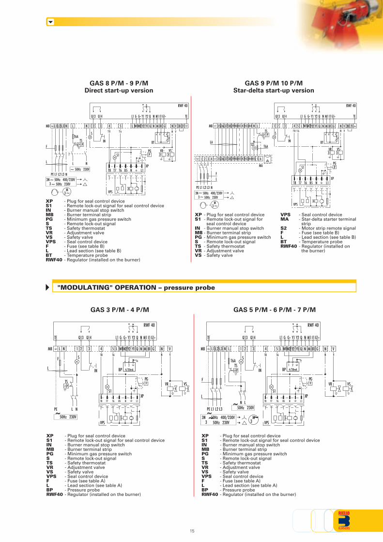
"MODULATING" OPERATION – pressure probe
GAS 8 P/M - 9 P/MDirect start-up version
GAS 9 P/M 10 P/MStar-delta start-up version
XP - Plug for seal control deviceS1 - Remote lock-out signal for seal control deviceIN - Burner manual stop switchMB - Burner terminal stripPG - Minimum gas pressure switchS - Remote lock-out signalTS - Safety thermostatVR - Adjustment valveVS - Safety valveVPS - Seal control deviceF - Fuse (see table B)L - Lead section (see table B)BT - Temperature probeRWF40 - Regulator (installed on the burner)
XP - Plug for seal control deviceS1 - Remote lock-out signal for
seal control deviceIN - Burner manual stop switchMB - Burner terminal stripPG - Minimum gas pressure switchS - Remote lock-out signalTS - Safety thermostatVR - Adjustment valveVS - Safety valve
VPS - Seal control deviceMA - Star-delta starter terminal
stripS2 - Motor strip remote signalF - Fuse (see table B)L - Lead section (see table B)BT - Temperature probeRWF40 - Regulator (installed on
the burner)
XP - Plug for seal control deviceS1 - Remote lock-out signal for seal control deviceIN - Burner manual stop switchMB - Burner terminal stripPG - Minimum gas pressure switchS - Remote lock-out signalTS - Safety thermostatVR - Adjustment valveVS - Safety valveVPS - Seal control deviceF - Fuse (see table A)L - Lead section (see table A)BP - Pressure probeRWF40 - Regulator (installed on the burner)
XP - Plug for seal control deviceS1 - Remote lock-out signal for seal control deviceIN - Burner manual stop switchMB - Burner terminal stripPG - Minimum gas pressure switchS - Remote lock-out signalTS - Safety thermostatVR - Adjustment valveVS - Safety valveVPS - Seal control deviceF - Fuse (see table A)L - Lead section (see table A)BP - Pressure probeRWF40 - Regulator (installed on the burner)
P
GAS 3 P/M - 4 P/M GAS 5 P/M - 6 P/M - 7 P/M
P
VR VS VR VS
~M3
~ 50Hz 230V3~3N 50Hz 400/230V
L1 L2 L3 N LMB 1 2 3 4 5
F
L
PE L1 L2 L3
T6A
NL
TS
S
~ 50Hz 230V
N
N
P
Y2 Y1 Q N M B1 G
IN
L N V 20 21N V
W1W2
T8
S1
T7 T6 B5 N L1XP
PPG
VPS
~M3
~ 50Hz 230V33N 50Hz 400/230V~
L1 L2 L3 N LMB 1 2
L
PE L1 L2 L3
T6A
N L
TS
S
IN
~50Hz 230V
3
F
~M3
4 5 N NL M B1Y2 Y1W1W2 Q VGN V
VR VS
T8 T6
S1
NT8 T6T7 L1
PG
XP
VPS
B5
NLMB 1 2
PE L N
F S
IN
3 4 N5 L
TS
M B1Y2 Y1W1W2 Q GT8 T6
S1
NT8 T6T7 L1
PG
XP
VPS
B5
N VN V
VR VS
Q13 Q14 QG- NL1 G+ G1+
~50Hz 230V3~3N 50Hz 400/230V
ϑ P
Q13 Q14 QG- NL1 G+ G1+
ϑ P
Q13 Q14 QG- NL1 G+ G1+
Q13 Q14 QG- NL1 G+ G1+
T 8 T 6
RWF 40
Y2Y1 M1 I1 TE
RWF 40
Y2Y1 M1 I1TE
~50Hz 230V
RWF 40
Y2Y1 M1 I1TE
RWF 40
Y2Y1 M1 I1 TE
BT
a b c d
BP 4/20mA21
BP 4/20mA21
3536 3738 LMB 1 2 3 4 5 L
FL
PE L1 L2 L3
T6A
TS S
N
P
Y2 Y1 Q N M B1 G
1 2 3 4 35 36 3738 39 40 41 42 43 44 45 5 6
39 40 41 42 43 44
S2
MA
LA
N
IN
T 8 T 6
T8
S1
T7 T6 B5 N L1XP
PPG
VPS
N V 20 21N V
W2W1
BT
a b c d
L
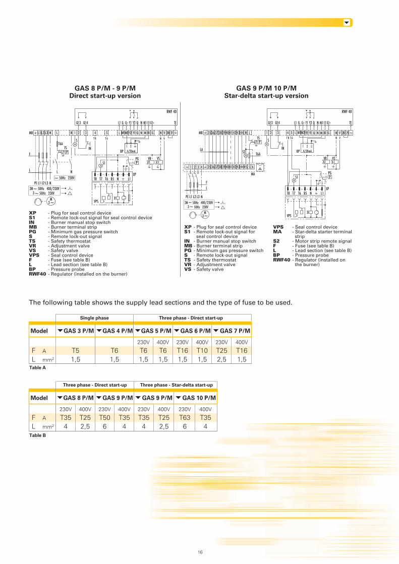
The following table shows the supply lead sections and the type of fuse to be used.
Table A
GAS 8 P/M - 9 P/MDirect start-up version
GAS 9 P/M 10 P/MStar-delta start-up version
XP - Plug for seal control deviceS1 - Remote lock-out signal for seal control deviceIN - Burner manual stop switchMB - Burner terminal stripPG - Minimum gas pressure switchS - Remote lock-out signalTS - Safety thermostatVR - Adjustment valveVS - Safety valveVPS - Seal control deviceF - Fuse (see table B)L - Lead section (see table B)BP - Pressure probeRWF40 - Regulator (installed on the burner)
XP - Plug for seal control deviceS1 - Remote lock-out signal for
seal control deviceIN - Burner manual stop switchMB - Burner terminal stripPG - Minimum gas pressure switchS - Remote lock-out signalTS - Safety thermostatVR - Adjustment valveVS - Safety valve
VPS - Seal control deviceMA - Star-delta starter terminal
stripS2 - Motor strip remote signalF - Fuse (see table B)L - Lead section (see table B)BP - Pressure probeRWF40 - Regulator (installed on
the burner)
Single phase Three phase - Direct start-up
Table B
Three phase - Direct start-up Three phase - Star-delta start-up
VR VS VR VS
GAS 3 P/M
230V
T61,5
400V
T61,5
230V
T161,5
400V
T101,5
230V
T252,5
400V
T161,5
Model
A
mm2
FL
230V
T51,5
~M3
~ 50Hz 230V3~3N 50Hz 400/230V
L1 L2 L3 N LMB 1 2 3 4 5
F
L
PE L1 L2 L3
T6A
NL
TS
S
~ 50Hz 230V
N
N
P
Y2 Y1 Q N M B1 G
IN
L N V 20 21N V
W1W2
T8
S1
T7 T6 B5 N L1XP
PPG
VPS
~M3
~ 50Hz 230V33N 50Hz 400/230V~
GAS 4 P/M
230V
T61,5
GAS 5 P/M GAS 6 P/M GAS 7 P/M
230V
T354
400V
T252,5
230V
T506
400V
T354
230V
T354
400V
T252,5
Model
A
mm2
FL
GAS 8 P/M GAS 9 P/M GAS 9 P/M
230V
T636
400V
T354
GAS 10 P/M
Q13 Q14 QG- NL1 G+ G1+
T 8 T 6
RWF 40
Y2Y1 M1 I1 TE
BP 4/20mA21
BP 4/20mA21
3536 3738 LMB 1 2 3 4 5 L
FL
PE L1 L2 L3
T6A
TS S
N
P
Y2 Y1 Q N M B1 G
1 2 3 4 35 36 3738 39 40 41 42 43 44 45 5 6
39 40 41 42 43 44
S2
MA
LA
N
IN
T 8 T 6
T8
S1
T7 T6 B5 N L1XP
PPG
VPS
N V 20 21N V
W2W1
16
Q13 Q14 QG- NL1 G+ G1+
RWF 40
Y2Y1 M1 I1 TE
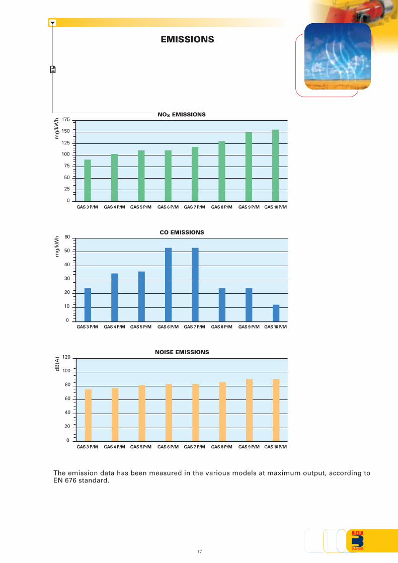
EMISSIONS
The emission data has been measured in the various models at maximum output, according toEN 676 standard.
GAS 3 P/M
mg
/kW
h
0
50
100
150
75
25
GAS 3 P/M GAS 4 P/M GAS 5 P/M GAS 6 P/M GAS 7 P/M GAS 8 P/M GAS 9 P/M
125
mg
/kW
h
0
10
20
30
40
50
dB
(A)
0
20
40
60
80
100
NOx EMISSIONS
CO EMISSIONS
NOISE EMISSIONS
175
GAS 10 P/M
GAS 3 P/M GAS 4 P/M GAS 5 P/M GAS 6 P/M GAS 7 P/M GAS 8 P/M GAS 9 P/M GAS 10 P/M
60
GAS 4 P/M GAS 5 P/M GAS 6 P/M GAS 7 P/M GAS 8 P/M GAS 9 P/M GAS 10 P/M
120
17
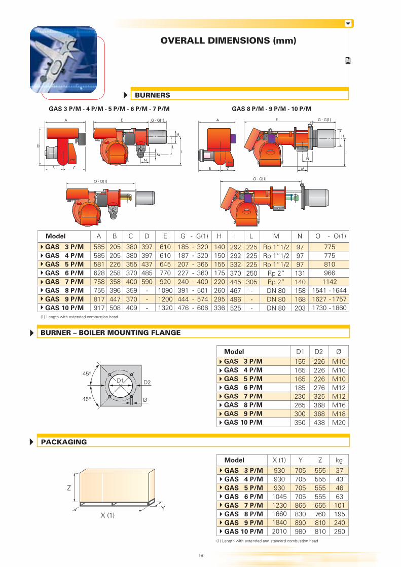
OVERALL DIMENSIONS (mm)
BURNERS
Ø
D2
45°
45°
D1
BURNER – BOILER MOUNTING FLANGE
X (1)
Z
Y
PACKAGING
GAS 3 P/M - 4 P/M - 5 P/M - 6 P/M - 7 P/M GAS 8 P/M - 9 P/M - 10 P/M
Model A B DC H
GAS 3 P/M
GAS 4 P/M
GAS 5 P/M
GAS 6 P/M
GAS 7 P/M
GAS 8 P/M
GAS 9 P/M
GAS 10 P/M
205205226258358396447508
585585581628758755817917
225225225250305
---
380380355370400359370409
G(1)
610610645770920109012001320
140150155175220260295336
G
185187207227240391444476
- I
979797131140158168203
L
397397437485590
---
E
Rp 1”1/2Rp 1”1/2Rp 1”1/2
Rp 2”Rp 2”DN 80DN 80DN 80
M
292292332370445467496525
N O(1)O
164417571860
154116271730
-
320320365360400501574606
7757758109661142
Model X (1) Y kg
93093093010451230
705705705705865830890980
37434663101195240290
Z
555555555555665760810810
166018402010
(1) Length with extended combustion head
A
B C
A
B
I
H
G - G(1)E
C M
N
E G - G(1)
H
I
N
LD
O - O(1)O - O(1)
(1) Length with extended and standard combustion head
18
GAS 3 P/M
GAS 4 P/M
GAS 5 P/M
GAS 6 P/M
GAS 7 P/M
GAS 8 P/M
GAS 9 P/M
GAS 10 P/M
M
--------
---
ØD2155165165185230265300350
M10M10M10M12M12M16M18M20
226226226276325368368438
D1Model
GAS 3 P/M
GAS 4 P/M
GAS 5 P/M
GAS 6 P/M
GAS 7 P/M
GAS 8 P/M
GAS 9 P/M
GAS 10 P/M
INSTALLATION DESCRIPTION
All the burners have slide bars, for easier installation and maintenance.
After drilling the boilerplate, using the supplied gasket as a template, dismantle the blast tubefrom the burner and fix it to the boiler.
Adjust the combustion head.
Fit the gas train, choosing this on the basis of the maximum output of the boiler and consideringthe enclosed diagrams.
Refit the burner casing to the slide bars.
Close the burner, sliding it up to the flange.
Make the electrical connections to the boiler following the wiring diagrams included in theinstruction handbook.
Turn the motor to check rotation direction (if it is a three-phase motor).
Perform a first ignition calibration on the gas train.
On start up, check:- Gas pressure at the combustion head (to max. and min. output)- Combustion quality, in terms of unburned substances and excess air.
Installation, start up and maintenance must be carried out byqualified and skilled personnel.All operations must be performed in accordance with the technical handbook supplied withthe burner.
BURNER SETTING
ELECTRICAL CONNECTIONS AND START UP
19
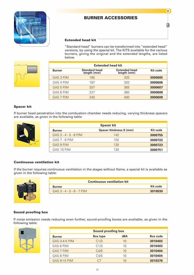
BURNER ACCESSORIES
Extended head kit
“Standard head” burners can be transformed into “extended head”versions, by using the special kit. The KITS available for the variousburners, giving the original and the extended lengths, are listedbelow.
Sound proofing box
If noise emission needs reducing even further, sound-proofing boxes are available, as given in thefollowing table:
Burner Box code
Sound proofing box
Box type
Kit codeBurner
Extended head kit
Extended headlength (mm)
GAS 3 P/M
GAS 4 P/M
GAS 5 P/M
GAS 6 P/M
GAS 7 P/M
320
320
365
360
400
3000605
3000606
3000607
3000608
3000609
Standard headlength (mm)
185
187
207
227
240
GAS 3-4-5 P/MGAS 6 P/MGAS 7 P/MGAS 8 P/MGAS 9-10 P/M
3010403
3010403
3010404
3010404
3010376
C1/3C1/3C4/5C4/5C7
dBA
1010101010
20
Continuous ventilation kit
If the burner requires continuous ventilation in the stages without flame, a special kit is available asgiven in the following table:
Burner Kit code
Continuous ventilation kit
GAS 3 - 4 - 5 - 6 - 7 P/M 3010030
Spacer kit
If burner head penetration into the combustion chamber needs reducing, varying thickness spacersare available, as given in the following table:
Burner Kit code
Spacer kit
Spacer thickness S (mm)
3000755
3000722
3000723
3000751
142102130130
GAS 3 - 4 - 5 - 6 P/MGAS 7 - 8 P/MGAS 9 P/MGAS 10 P/M
S
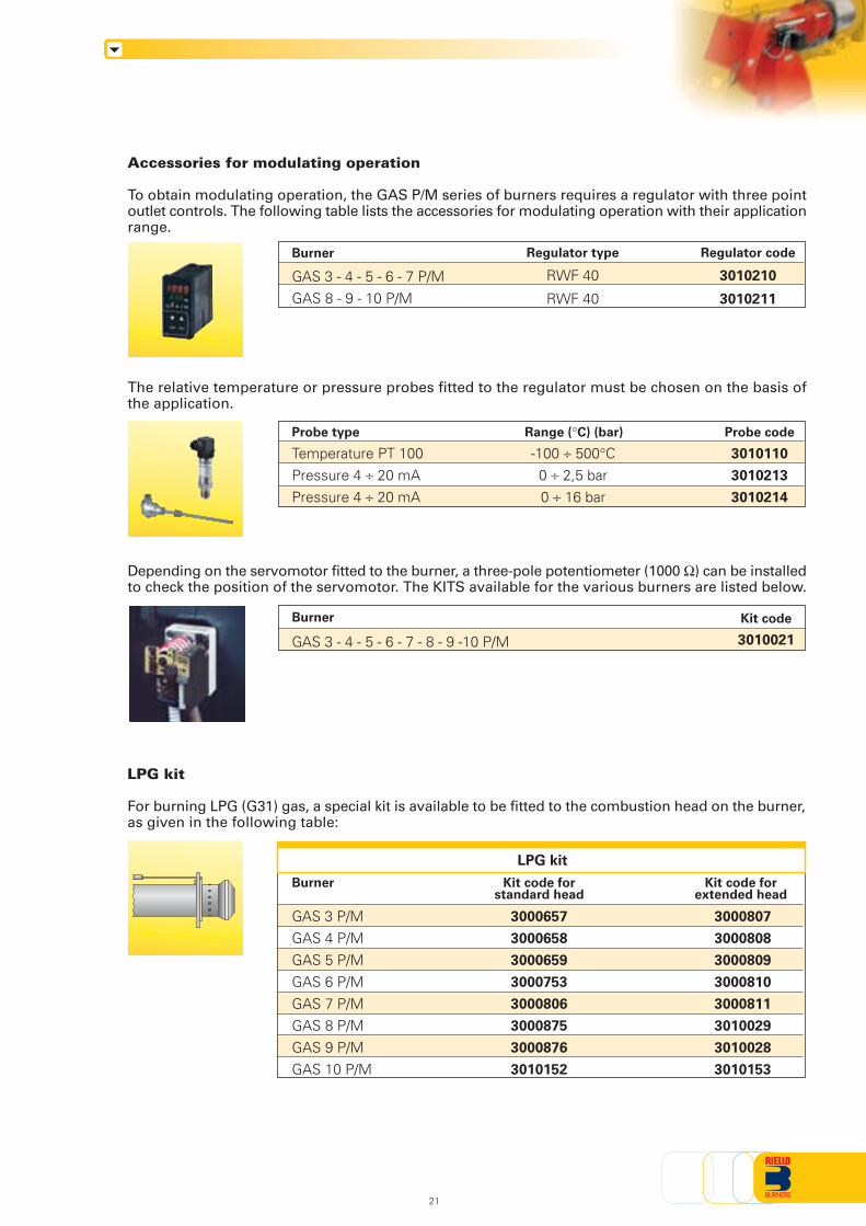
Accessories for modulating operation
To obtain modulating operation, the GAS P/M series of burners requires a regulator with three pointoutlet controls. The following table lists the accessories for modulating operation with their applicationrange.
The relative temperature or pressure probes fitted to the regulator must be chosen on the basis ofthe application.
Depending on the servomotor fitted to the burner, a three-pole potentiometer (1000 Ω) can be installedto check the position of the servomotor. The KITS available for the various burners are listed below.
21
Burner
LPG kit
Kit code forextended head
Kit code forstandard head
LPG kit
For burning LPG (G31) gas, a special kit is available to be fitted to the combustion head on the burner,as given in the following table:
GAS 3 P/MGAS 4 P/MGAS 5 P/MGAS 6 P/MGAS 7 P/MGAS 8 P/MGAS 9 P/MGAS 10 P/M
3000807
3000808
3000809
3000810
3000811
3010029
3010028
3010153
3000657
3000658
3000659
3000753
3000806
3000875
3000876
3010152
Burner Kit code
3010021GAS 3 - 4 - 5 - 6 - 7 - 8 - 9 -10 P/M
Probe type
Temperature PT 100Pressure 4 ÷ 20 mAPressure 4 ÷ 20 mA
Range (°C) (bar)
-100 ÷ 500°C0 ÷ 2,5 bar0 ÷ 16 bar
Probe code
3010110
3010213
3010214
Regulator type
RWF 40
RWF 40
Regulator code
3010210
3010211
GAS 3 - 4 - 5 - 6 - 7 P/MGAS 8 - 9 - 10 P/M
Burner
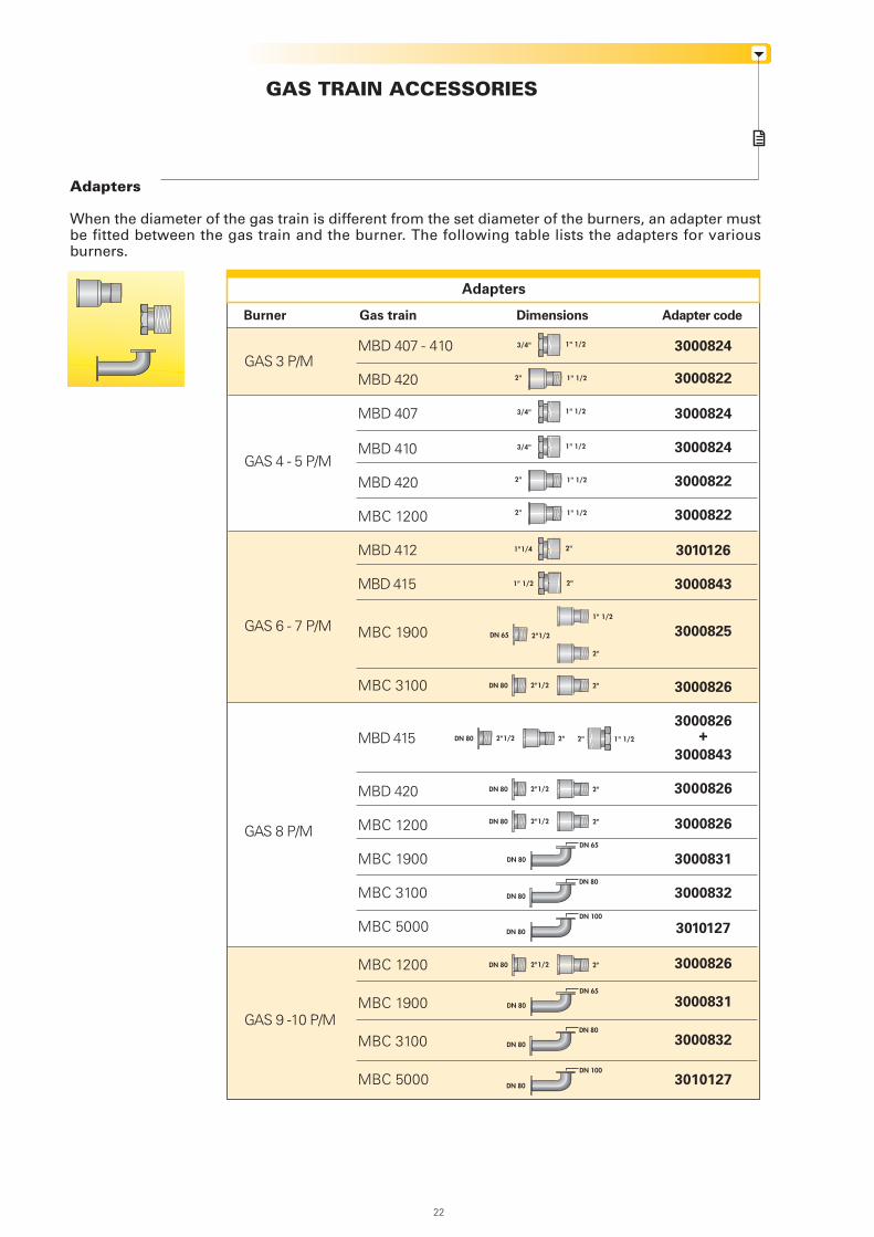
GAS TRAIN ACCESSORIES
Adapters
Adapters
When the diameter of the gas train is different from the set diameter of the burners, an adapter mustbe fitted between the gas train and the burner. The following table lists the adapters for variousburners.
Burner Gas train Adapter codeDimensions
1" 1/2 2"
1" 1/23/4"
2" 1" 1/2
1" 1/23/4"
2" 1" 1/2
1" 1/23/4"
2" 1" 1/2
2"1"1/4
1" 1/22"
GAS 3 P/M
GAS 4 - 5 P/M
GAS 6 - 7 P/M
GAS 8 P/M
GAS 9 -10 P/M
MBD 407 - 410
MBD 420
MBD 407
MBD 410
MBD 420
MBC 1200
MBD 412
MBD 415
MBC 1900
MBC 3100
MBD 415
MBD 420
MBC 1200
MBC 1900
MBC 3100
MBC 5000
MBC 1200
MBC 1900
MBC 3100
MBC 5000
3000824
3000822
3000824
3000824
3000822
3000822
3010126
3000843
3000825
3000826
3000826+
3000843
3000826
3000826
3000831
3000832
3010127
3000826
3000831
3000832
3010127
DN 80
DN 80
DN 80
DN 100
DN 80
DN 65
DN 80
DN 80
DN 80
DN 100
DN 80
DN 65
22
DN 65 2"1/2
2"
1" 1/2
DN 80 2"1/2 2"
DN 80 2"1/2 2"
DN 80 2"1/2 2"
DN 80 2"1/2 2"
DN 80 2"1/2 2"
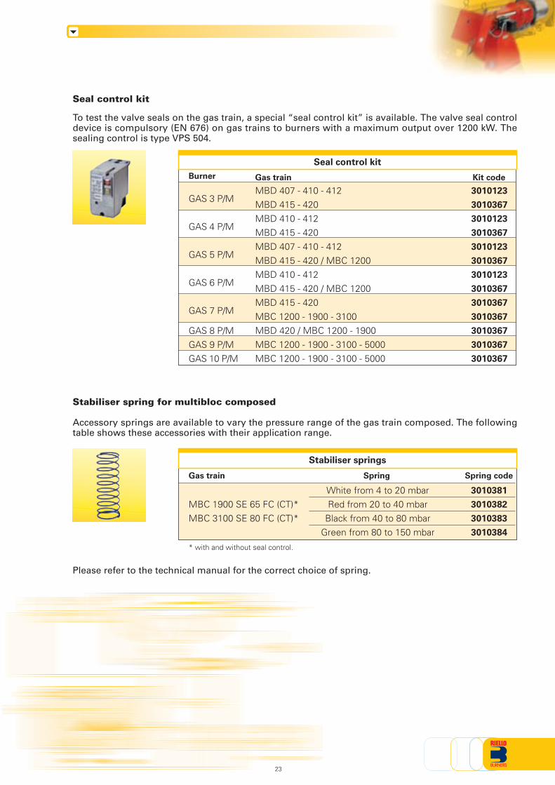
Seal control kit
To test the valve seals on the gas train, a special “seal control kit” is available. The valve seal controldevice is compulsory (EN 676) on gas trains to burners with a maximum output over 1200 kW. Thesealing control is type VPS 504.
Burner
Seal control kit
GAS 3 P/M
GAS 4 P/M
GAS 5 P/M
GAS 6 P/M
GAS 7 P/M
GAS 8 P/MGAS 9 P/MGAS 10 P/M
Kit code
3010123
3010367
3010123
3010367
3010123
3010367
3010123
3010367
3010367
3010367
3010367
3010367
3010367
Gas train
MBD 407 - 410 - 412MBD 415 - 420MBD 410 - 412MBD 415 - 420MBD 407 - 410 - 412MBD 415 - 420 / MBC 1200MBD 410 - 412MBD 415 - 420 / MBC 1200MBD 415 - 420MBC 1200 - 1900 - 3100MBD 420 / MBC 1200 - 1900MBC 1200 - 1900 - 3100 - 5000MBC 1200 - 1900 - 3100 - 5000
Stabiliser spring for multibloc composed
Accessory springs are available to vary the pressure range of the gas train composed. The followingtable shows these accessories with their application range.
Please refer to the technical manual for the correct choice of spring.
Stabiliser springs
MBC 1900 SE 65 FC (CT)*MBC 3100 SE 80 FC (CT)*
Gas train Spring codeSpring
3010381
3010382
3010383
3010384
White from 4 to 20 mbarRed from 20 to 40 mbar
Black from 40 to 80 mbarGreen from 80 to 150 mbar
* with and without seal control.
23
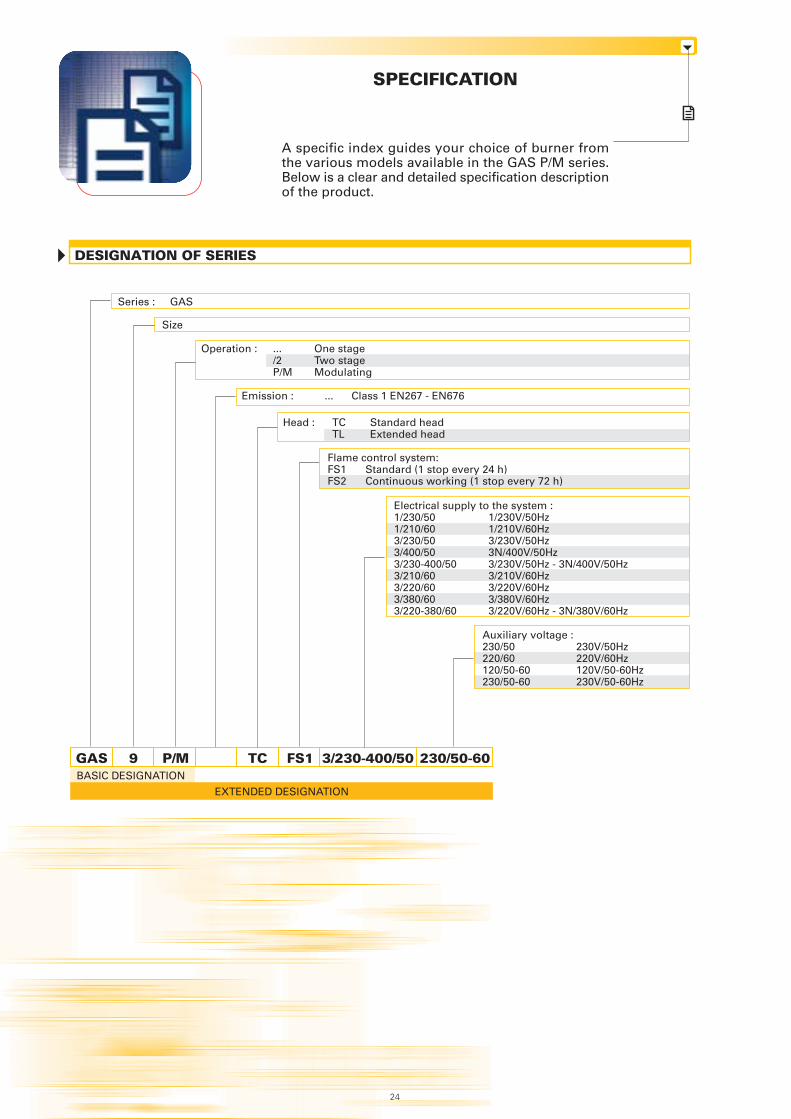
A specific index guides your choice of burner fromthe various models available in the GAS P/M series.Below is a clear and detailed specification descriptionof the product.
SPECIFICATION
DESIGNATION OF SERIES
9 TC FS1 3/230-400/50 230/50-60
Size
Series : GAS
BASIC DESIGNATION
EXTENDED DESIGNATION
Operation : ... One stage/2 Two stageP/M Modulating
Emission : ... Class 1 EN267 - EN676
Head : TC Standard headTL Extended head
P/MGAS
24
Flame control system: FS1 Standard (1 stop every 24 h)FS2 Continuous working (1 stop every 72 h)
Electrical supply to the system :1/230/50 1/230V/50Hz1/210/60 1/210V/60Hz3/230/50 3/230V/50Hz3/400/50 3N/400V/50Hz3/230-400/50 3/230V/50Hz - 3N/400V/50Hz3/210/60 3/210V/60Hz3/220/60 3/220V/60Hz3/380/60 3/380V/60Hz3/220-380/60 3/220V/60Hz - 3N/380V/60Hz
Auxiliary voltage :230/50 230V/50Hz220/60 220V/60Hz120/50-60 120V/50-60Hz230/50-60 230V/50-60Hz
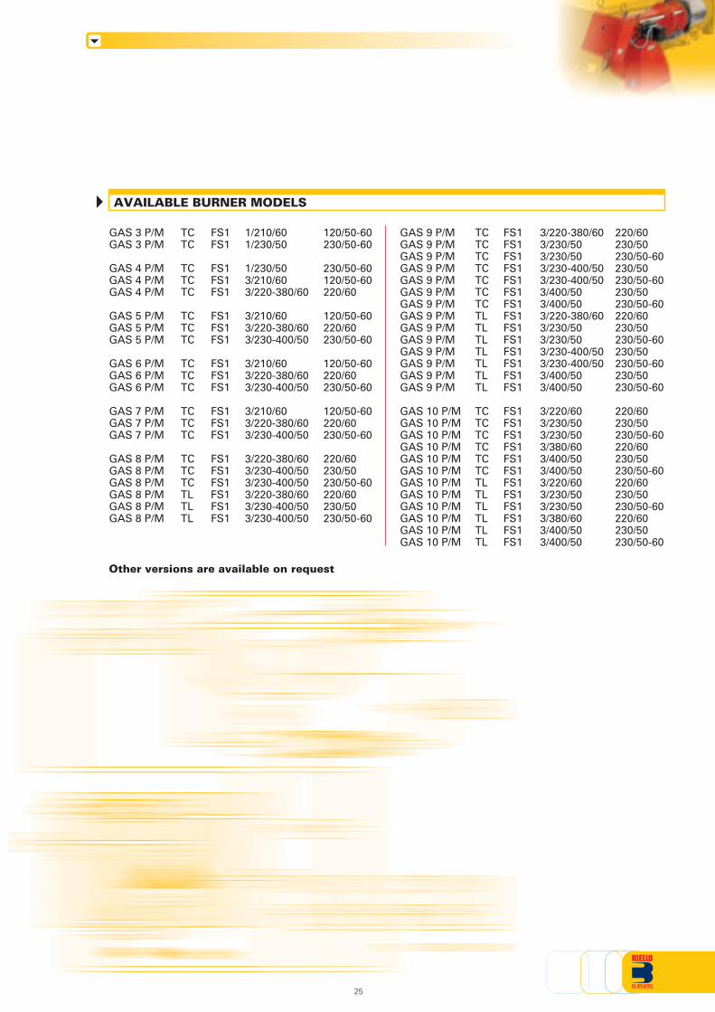
AVAILABLE BURNER MODELS
Other versions are available on request
25
GAS 3 P/M TC FS1 1/210/60 120/50-60GAS 3 P/M TC FS1 1/230/50 230/50-60
GAS 4 P/M TC FS1 1/230/50 230/50-60GAS 4 P/M TC FS1 3/210/60 120/50-60GAS 4 P/M TC FS1 3/220-380/60 220/60
GAS 5 P/M TC FS1 3/210/60 120/50-60GAS 5 P/M TC FS1 3/220-380/60 220/60GAS 5 P/M TC FS1 3/230-400/50 230/50-60
GAS 6 P/M TC FS1 3/210/60 120/50-60GAS 6 P/M TC FS1 3/220-380/60 220/60GAS 6 P/M TC FS1 3/230-400/50 230/50-60
GAS 7 P/M TC FS1 3/210/60 120/50-60GAS 7 P/M TC FS1 3/220-380/60 220/60GAS 7 P/M TC FS1 3/230-400/50 230/50-60
GAS 8 P/M TC FS1 3/220-380/60 220/60GAS 8 P/M TC FS1 3/230-400/50 230/50GAS 8 P/M TC FS1 3/230-400/50 230/50-60GAS 8 P/M TL FS1 3/220-380/60 220/60GAS 8 P/M TL FS1 3/230-400/50 230/50GAS 8 P/M TL FS1 3/230-400/50 230/50-60
GAS 9 P/M TC FS1 3/220-380/60 220/60GAS 9 P/M TC FS1 3/230/50 230/50GAS 9 P/M TC FS1 3/230/50 230/50-60GAS 9 P/M TC FS1 3/230-400/50 230/50GAS 9 P/M TC FS1 3/230-400/50 230/50-60GAS 9 P/M TC FS1 3/400/50 230/50GAS 9 P/M TC FS1 3/400/50 230/50-60GAS 9 P/M TL FS1 3/220-380/60 220/60GAS 9 P/M TL FS1 3/230/50 230/50GAS 9 P/M TL FS1 3/230/50 230/50-60GAS 9 P/M TL FS1 3/230-400/50 230/50GAS 9 P/M TL FS1 3/230-400/50 230/50-60GAS 9 P/M TL FS1 3/400/50 230/50GAS 9 P/M TL FS1 3/400/50 230/50-60
GAS 10 P/M TC FS1 3/220/60 220/60GAS 10 P/M TC FS1 3/230/50 230/50GAS 10 P/M TC FS1 3/230/50 230/50-60GAS 10 P/M TC FS1 3/380/60 220/60GAS 10 P/M TC FS1 3/400/50 230/50GAS 10 P/M TC FS1 3/400/50 230/50-60GAS 10 P/M TL FS1 3/220/60 220/60GAS 10 P/M TL FS1 3/230/50 230/50GAS 10 P/M TL FS1 3/230/50 230/50-60GAS 10 P/M TL FS1 3/380/60 220/60GAS 10 P/M TL FS1 3/400/50 230/50GAS 10 P/M TL FS1 3/400/50 230/50-60
26
Burner:
Monoblock forced draught gas burner, two stage progressive operation or modulating with a kit, madeup of:- Air suction circuit- Fan with forward curved blades- Air damper for air setting controlled by a servomotor;- Combustion head, that can be set on the basis of required output, fitted with:
- stainless steel end cone, resistant to corrosion and high temperatures- ignition electrodes- flame stability disk
- Servomotor for air and gas delivery regulation- Maximum gas pressure switch- Minimum air pressure switch- Single phase or three phases electrical motor- Ionisation probe- UV photocell for flame detection- Flame inspection window- Slide bars for easier installation and maintenance- Protection filter against radio interference- IP 40 protection level.
Gas trainFuel supply line, in the MULTIBLOC configuration (from a diameter of 3/4” until a diameter 2”) orCOMPOSED configuration (from a diameter of DN 65 until a diameter of DN 100), fitted with:- Filter- Stabiliser- Minimum gas pressure switch- Safety valve- Valve seal control (for output > 1200 kW)- One stage working valve with ignition gas output regulator.
Conforming to:- 89/336/EEC directive (electromagnetic compatibility)- 73/23/EEC directive (low voltage)- 92/42/EEC directive (performance)- 90/396/EEC directive (gas)- EN 676 (gas burners).
Standard equipment:- 1 gas train gasket- 1 flange gasket- 1 insulating screen- 8 screws for fixing the burner flange to the boiler (12 for GAS 8 P/M - GAS 9 P/M and GAS 10 P/M)- 4 wiring looms for electrical connections- 1 star delta starter (for GAS 8 P/M - GAS 9 P/M and GAS 10 P/M)- 2 wiring looms for electrical connections to the star delta starter (for GAS 8 P/M - GAS 9 P/M and GAS 10 P/M)- 8 washers (for GAS 8 P/M - GAS 9 P/M and GAS 10 P/M)- 2 bar extensions (only for long head versions of GAS 8 P/M - GAS 9 P/M and GAS 10 P/M)- Instruction handbook for installation, use and maintenance- Spare parts catalogue.
Available accessories to be ordered separately:- Head extension kit- Head length reduction kit- Continuous ventilation kit- Sound-proofing box- RWF 40 output regulator- Pressure probe 0 – 2.4 bar- Pressure probe 0 – 16 bar- Temperature probe -100 – 500°C- Potentiometer kit for the servomotor- LPG kit- Gas train adapter- Seal control kit- Stabiliser spring.
PRODUCT SPECIFICATION

27

ISO 9001 Cert. n. 0061
RIELLO S.p.A. - Via Ing. Pilade Riello, 5 - 37045 Legnago (VR) ItalyTel. ++39.0442630111 - Fax ++39.044221980
Internet: http://www.rielloburners.com - E-mail: [email protected]
Since the Company is constantly engaged in the production improvement, the aesthetic anddimensional features, the technical data, the equipment and the accessories can be changed.
This document contains confidential and proprietary information of RIELLO S.p.A.Unless authorised, this information shall not be divulged, nor duplicated in whole or in part.