Embed Size (px)
Citation preview

Modular transfer system
24 Volts
ITS - TLM 2000
User & maintenance manual
I02-244 / Translation of the original manual, version 03
I02-244 User & maintenance manual Version 02 (translation of the original manual) of TLM2000 ITS 24 V
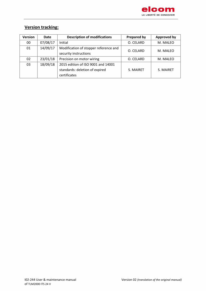
Version tracking:
Version Date Description of modifications Prepared by Approved by
00 07/08/17 Initial O. CELARD M. MALEO
01 14/09/17 Modification of stopper reference and
security instructions O. CELARD M. MALEO
02 23/01/18 Precision on motor wiring O. CELARD M. MALEO
03 18/09/18 2015 edition of ISO 9001 and 14001
standards: deletion of expired
certificates
S. MAIRET S. MAIRET

I02-244 User & maintenance manual Version 03 (translation of the original manual) of TLM2000 ITS 24 V Page 1 of 32
Table of content
1 GEnEral information .........................................................................................................................1
1.1 Important notice ..................................................................................................................... 1
1.2 Applicable standards ............................................................................................................... 1
1.3 Applications ............................................................................................................................. 1
1.4 Terms of use ............................................................................................................................ 1
1.5 Security instructions ................................................................................................................ 2
1.6 Motor’s safety instructions ..................................................................................................... 2
1.7 Additional information ............................................................................................................ 3
http://elcom-automation.com/transfers/documentation ................................................................. 3
2 Technical caracteristics ....................................................................................................................3
3 Commisionning .................................................................................................................................4
3.1 Receipt of equipment .............................................................................................................. 4
3.2 Stopper .................................................................................................................................... 4
3.3 Positioning unit ........................................................................................................................ 5
3.4 Double cam .............................................................................................................................. 6
3.5 Derivation ................................................................................................................................ 7
3.6 Workpiece carrier .................................................................................................................... 8
4 Maintenance ....................................................................................................................................9
4.1 Belts wear ................................................................................................................................ 9
Regularly verify visually the state of the belt and especially the welding area .................................. 9
4.2 Passageways of workpiece carriers ......................................................................................... 9
4.3 Pins .......................................................................................................................................... 9
4.4 Wear of the belt guide ............................................................................................................ 9
4.5 Transfert parts ....................................................................................................................... 10
4.6 Stoppers ................................................................................................................................ 10
4.7 Positioning unit ...................................................................................................................... 11
4.8 Double cam ............................................................................................................................ 12
Clean all double cams. ....................................................................................................................... 12
4.9 Derivation .............................................................................................................................. 12
4.10 Other elements of the transfert ............................................................................................ 12
5 changeout of the 24V drive motor ................................................................................................ 13
6 Changeout of the drive motor of index unit 24v ........................................................................... 16
7 Changeout the drive belt ............................................................................................................... 18
8 wiring the 24v drives motors ......................................................................................................... 19
9 Wiring of the drive motor of index unit 24v.................................................................................. 20

I02-244 User & maintenance manual Version 02 (translation of the original manual) of TLM2000 ITS 24 V
10 wiring of the 24v stoppers............................................................................................................. 24
10.1 Connectic required to wire the electrical stoppers ............................................................... 24
10.2 Wiring of the control box of the stoppers ............................................................................. 25
10.3 Connectic required to wire the doubles cams and derivations ............................................ 26
10.4 Wiring of the control box of the double cam 24V or derivation 24V .................................... 28
11 Responsability ............................................................................................................................... 30
12 Customer service ........................................................................................................................... 30
13 Appendix ........................................................................................................................................ 31
13.1 Maintenance schedule .......................................................................................................... 31
13.2 Quality and environmental commitment: ISO certifications ................................................ 32

I02-244 User & maintenance manual Version 03 (translation of the original manual) of TLM2000 ITS 24 V Page 1 of 32
1 GENERAL INFORMATION 1.1 Important notice The following instructions are used as technical documentation for the manufacturer of the final machine system. elcom company is the provider of the subset transfer system TLM 2000 ITS 24V.
The manufacturer of the final machine system must ensure that all safety equipment is provided and functional, that regular checks are made, that any danger arising from moving parts is controlled or reported (pinch, shear) and that the documentation is complete.
1.2 Applicable standards The machine system where the subset is incorporated cannot be in service until all the terms and conditions established by directive 2006/42/CE have not been applied.
According to the European Directive 2006/42/CE, elcom transfer systems are considered as almost full machine system. Then, they are not subject to EC declaration of conformity.
However, the following standards are considered for the design of elcom transfers:
× 2006/42/CE directive related to machine systems
× 73/23/CE directive related to electrical equipment
Elcom company provides monitoring and quality recognized by the ISO 9001 certification.
Regarding the environment respect, elcom company is also ISO 14001 certified.
1.3 Applications Les éléments de transfert linéaire TLM 2000-ITS24V sont prévus pour le déplacement et le positionnement de palettes porte pièces suivant la configuration demandée pour le client final.
Ils sont destinés à être incorporés dans la ligne complète du client.
1.4 Terms of use The elements of the TLM 2000 ITS24V transfer system is provided for a normal use in industrial workshop, type assembly or equivalent, in a dry environment.
They are not suitable for the transport of materials such as sand, granules or grains.
The maximum load applicable to the transfer system is specified in the catalog and must always be strictly followed.
To ensure a proper operation of the transfer and an optimal lifetime, using shall be focused on the followings :
× Operating temperatures between 0° and 40° C, × Avoid dusty or smoky atmospheres, × Avoid accumulation of sharp edged objects on conveyor, × Avoid positioning of the machine under direct exposure to UV rays.
I02-244 User & maintenance manual Version 03 (translation of the original manual) of TLM2000 ITS 24 V Page 2 of 32
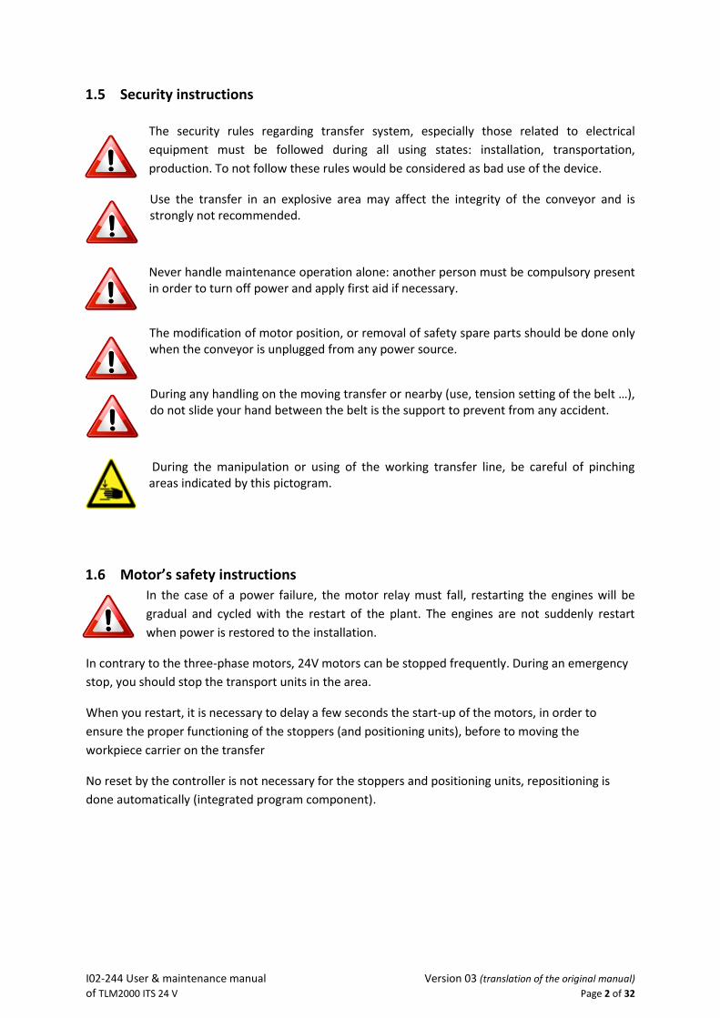
1.5 Security instructions
The security rules regarding transfer system, especially those related to electrical
equipment must be followed during all using states: installation, transportation,
production. To not follow these rules would be considered as bad use of the device.
Use the transfer in an explosive area may affect the integrity of the conveyor and is strongly not recommended.
Never handle maintenance operation alone: another person must be compulsory present in order to turn off power and apply first aid if necessary.
The modification of motor position, or removal of safety spare parts should be done only when the conveyor is unplugged from any power source.
During any handling on the moving transfer or nearby (use, tension setting of the belt …), do not slide your hand between the belt is the support to prevent from any accident.
During the manipulation or using of the working transfer line, be careful of pinching areas indicated by this pictogram.
1.6 Motor’s safety instructions
In the case of a power failure, the motor relay must fall, restarting the engines will be
gradual and cycled with the restart of the plant. The engines are not suddenly restart
when power is restored to the installation.
In contrary to the three-phase motors, 24V motors can be stopped frequently. During an emergency
stop, you should stop the transport units in the area.
When you restart, it is necessary to delay a few seconds the start-up of the motors, in order to
ensure the proper functioning of the stoppers (and positioning units), before to moving the
workpiece carrier on the transfer
No reset by the controller is not necessary for the stoppers and positioning units, repositioning is
done automatically (integrated program component).

I02-244 User & maintenance manual Version 03 (translation of the original manual) of TLM2000 ITS 24 V Page 3 of 32
1.7 Additional information The aim of these instructions is to guarantee people safety and proper use of the transfer system. If you wish to use the transfer system in any other conditions, don’t hesitate to contact us.
More information is available on elcom website:
http://elcom-automation.com/transfers/documentation
2 TECHNICAL CARACTERISTICS
- Maximum weight on workpiece carrier : 10 kg (except workpiece carrier)
- Maximum weight accumulation on stopper: 50 kg for a maximum stretch of 3 meters.
- Electric tension alimentation for motors: Direct 24 V
- Power consumption by motors : C = 0 (no load) → P < 10W (C= load in kilograms) C = 35Kg → 20W < P < 50W Installed power for this equipment : 220 V - 150 W - Emission sonore : < 80 dB
- Module weight : See the catalog « Transfert linéaire modulaire & convoyeurs à bandes ».
http://www.elcom.fr/transferts/documentation
Warning ! Every overload can lead to advanced damage for the belt or any other
element.

I02-244 User & maintenance manual Version 03 (translation of the original manual) of TLM2000 ITS 24 V Page 4 of 32
3 COMMISIONNING
3.1 Receipt of equipment
When receiving the material, check that the packaging has not been damaged and that the equipment is in perfect condition.
3.2 Stopper
1. lace the stopper right in the middle of the two profiles of the system. 2. Put the workpiece carrier in contact of the stopper. 3. Adjust the presence detection range :
- Move the sensor support to align the sensor with the cam of the workpiece carrier (the sensor must pass 1)
- When the sensor returns to 0, the stop back into the groove of the workpiece carrier.
Sensor
support
Cam
Work piece carrier
against the stopper
Stopper

I02-244 User & maintenance manual Version 03 (translation of the original manual) of TLM2000 ITS 24 V Page 5 of 32
3.3 Positioning unit
1. Place the stopper right in the middle of the two profiles of the system. 2. The presence detection range is preset.
Presence
detector range

I02-244 User & maintenance manual Version 03 (translation of the original manual) of TLM2000 ITS 24 V Page 6 of 32
3.4 Double cam
See overall drawing and assembly N°: 120 21 000 E
I02-244 User & maintenance manual Version 03 (translation of the original manual) of TLM2000 ITS 24 V Page 7 of 32
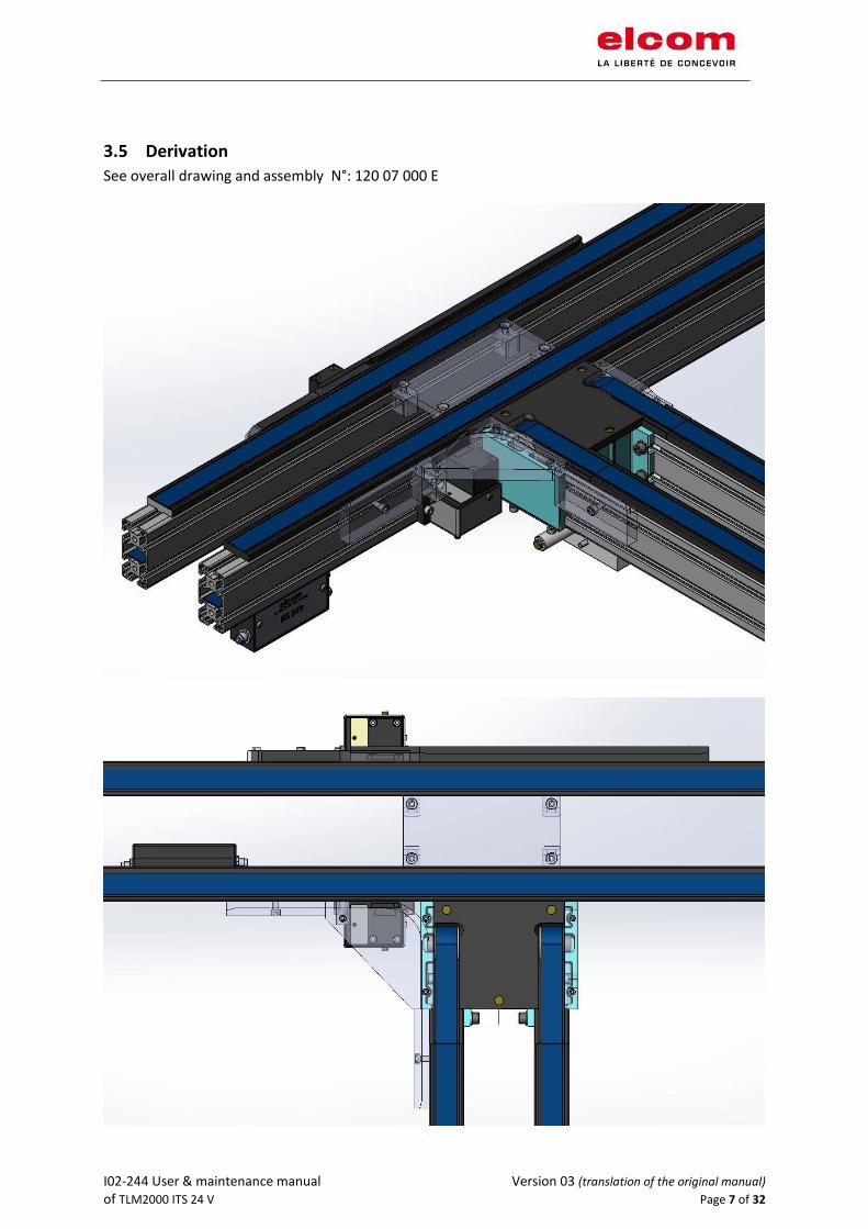
3.5 Derivation
See overall drawing and assembly N°: 120 07 000 E

I02-244 User & maintenance manual Version 03 (translation of the original manual) of TLM2000 ITS 24 V Page 8 of 32
3.6 Workpiece carrier
1. Check the function of the springs and the pins under the workpiece carrier.
2. Check that no part goes over the lower surface of the workpiece carrier.
4 Pins
Stopper
groove

I02-244 User & maintenance manual Version 03 (translation of the original manual) of TLM2000 ITS 24 V Page 9 of 32
4 MAINTENANCE
General visual check
Approximately every 500 hours, check the following points to ensure the proper functioning of the
transfer system.
4.1 Belts wear
Regularly verify visually the state of the belt and especially the welding area
4.2 Passageways of workpiece carriers
The friction of the pins while operating can make some marks appear. Those marks may over the
long term require the part replacement.
4.3 Pins
Pins are sensitive to wear, especially if the load is heavy. Wear can be noticed as soon as a loss of
efficiency in the guiding of the workpiece carrier.
4.4 Wear of the belt guide
Belt guide must be replaced as soon as wear marks or friction on the belt start to appear.
Wear area of the pins
Belt
Belt guide
I02-244 User & maintenance manual Version 03 (translation of the original manual) of TLM2000 ITS 24 V Page 10 of 32
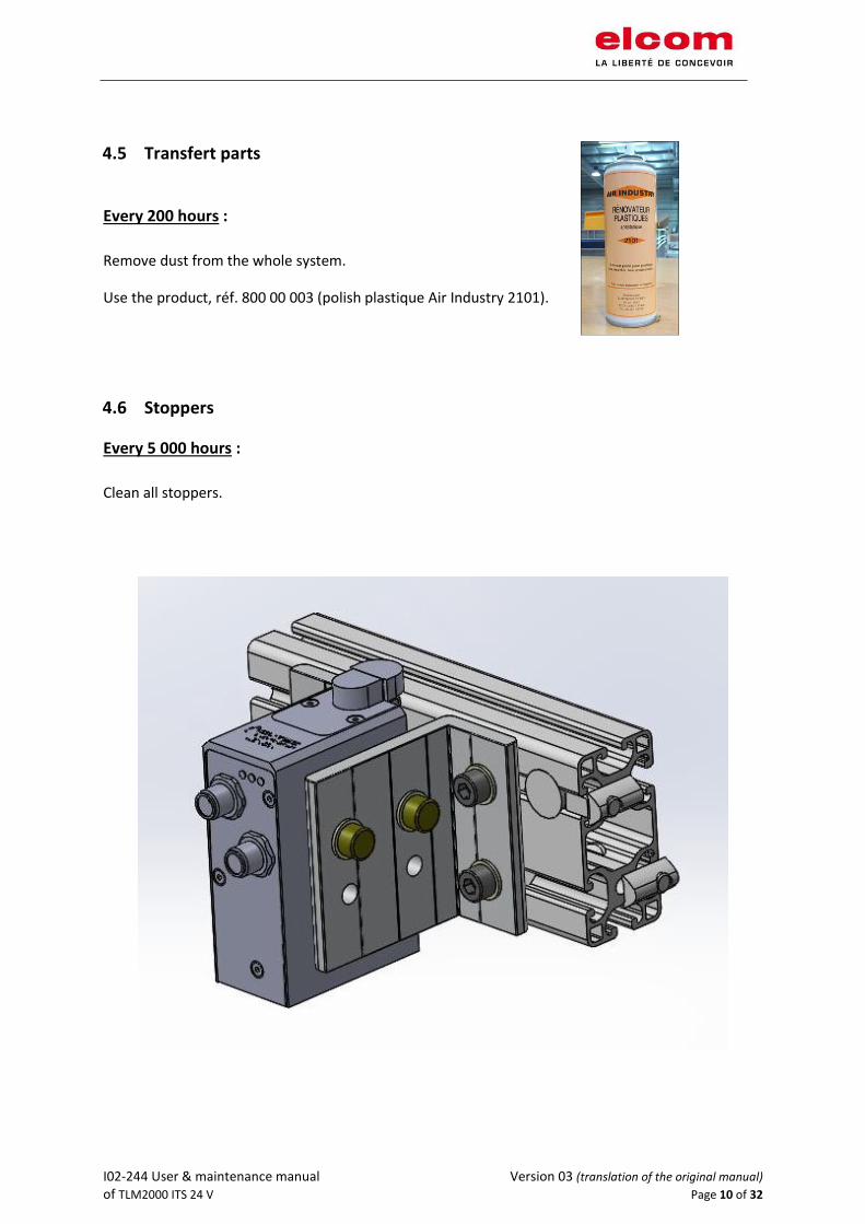
4.5 Transfert parts
Every 200 hours :
Remove dust from the whole system.
Use the product, réf. 800 00 003 (polish plastique Air Industry 2101).
4.6 Stoppers
Every 5 000 hours :
Clean all stoppers.
I02-244 User & maintenance manual Version 03 (translation of the original manual) of TLM2000 ITS 24 V Page 11 of 32
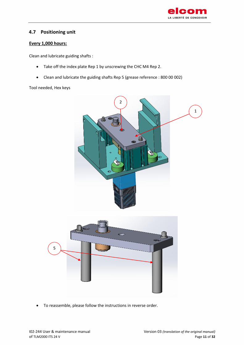
4.7 Positioning unit
Every 1,000 hours:
Clean and lubricate guiding shafts :
• Take off the index plate Rep 1 by unscrewing the CHC M4 Rep 2.
• Clean and lubricate the guiding shafts Rep 5 (grease reference : 800 00 002)
Tool needed, Hex keys
• To reassemble, please follow the instructions in reverse order.
1
2
5

I02-244 User & maintenance manual Version 03 (translation of the original manual) of TLM2000 ITS 24 V Page 12 of 32
4.8 Double cam
Every 5,000 hours :
Clean all double cams.
4.9 Derivation
Every 5,000 hours :
Clean all derivations.
4.10 Other elements of the transfert
Other elements do not require a specific maintenance.
A regular visual control is advised to check if there is no broken components and to control wear
parts.

I02-244 User & maintenance manual Version 03 (translation of the original manual) of TLM2000 ITS 24 V Page 13 of 32
5 CHANGEOUT OF THE 24V DRIVE MOTOR ❑ Shut down the machine that integrate the transfer system.
❑ Switch off the machine.
❑ Disconnect the wires of the drive to replace.
❑ Take off the mechanical part Rep 13 between the transmission bloc and the drive motor
support, fixed by 2 srews CHC M5 Rep 14 (see picture below) Tool needed, Hex keys
Drive motor documentation :
http://img.ebmpapst.com/products/datasheets/VDC34915K4B00-1454904.pdf
14 13 Drive motor reference : 150 50 251

I02-244 User & maintenance manual Version 03 (translation of the original manual) of TLM2000 ITS 24 V Page 14 of 32
❑ Take off the carter fixed by 4 screws CHC M5 Rep 9.
❑ Loosen the screw CHC M6 Rep 8, to ensures the tension of the belt.
❑ Loosen the 2 screws CHC M6 Rep 10, fastener the drive motor support Rep 7.
❑ Take off the belt.
9
Carter
8 10 7 Belt

I02-244 User & maintenance manual Version 03 (translation of the original manual) of TLM2000 ITS 24 V Page 15 of 32
❑ Take off the pulley Rep 5 blocked by a screw M4 Rep 6
❑ Take off the drive motor fixed by 4 screws CHC M5 Rep 11
To reassemble, please follow the instructions in reverse order.
5 6 11
I02-244 User & maintenance manual Version 03 (translation of the original manual) of TLM2000 ITS 24 V Page 16 of 32
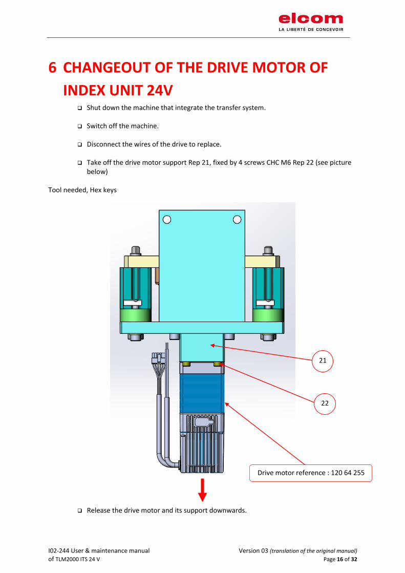
6 CHANGEOUT OF THE DRIVE MOTOR OF
INDEX UNIT 24V ❑ Shut down the machine that integrate the transfer system.
❑ Switch off the machine.
❑ Disconnect the wires of the drive to replace.
❑ Take off the drive motor support Rep 21, fixed by 4 screws CHC M6 Rep 22 (see picture
below) Tool needed, Hex keys
❑ Release the drive motor and its support downwards.
21
22
Drive motor reference : 120 64 255
I02-244 User & maintenance manual Version 03 (translation of the original manual) of TLM2000 ITS 24 V Page 17 of 32
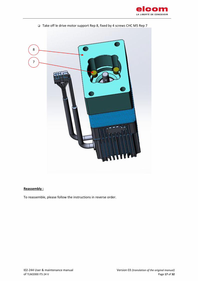
❑ Take off le drive motor support Rep 8, fixed by 4 screws CHC M5 Rep 7
Reassembly :
To reassemble, please follow the instructions in reverse order.
8
7
I02-244 User & maintenance manual Version 03 (translation of the original manual) of TLM2000 ITS 24 V Page 18 of 32
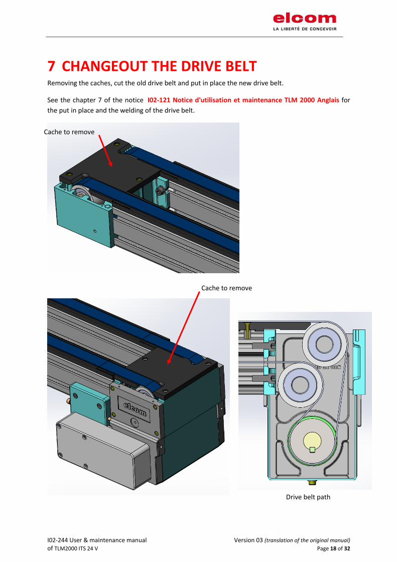
7 CHANGEOUT THE DRIVE BELT Removing the caches, cut the old drive belt and put in place the new drive belt.
See the chapter 7 of the notice I02-121 Notice d'utilisation et maintenance TLM 2000 Anglais for
the put in place and the welding of the drive belt.
Cache to remove
Cache to remove
Drive belt path
I02-244 User & maintenance manual Version 03 (translation of the original manual) of TLM2000 ITS 24 V Page 19 of 32
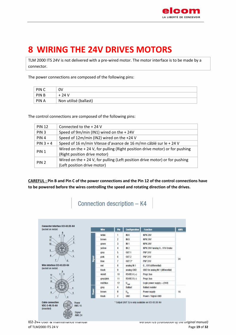
8 WIRING THE 24V DRIVES MOTORS TLM 2000 ITS 24V is not delivered with a pre-wired motor. The motor interface is to be made by a
connector.
The power connections are composed of the following pins:
PIN C 0V
PIN B + 24 V
PIN A Non utilisé (ballast)
The control connections are composed of the following pins:
PIN 12 Connected to the + 24 V
PIN 3 Speed of 9m/min (IN1) wired on the + 24V
PIN 4 Speed of 12m/min (IN2) wired on the +24 V
PIN 3 + 4 Speed of 16 m/min Vitesse d’avance de 16 m/mn câblé sur le + 24 V
PIN 1 Wired on the + 24 V, for pulling (Right position drive motor) or for pushing (Right position drive motor)
PIN 2 Wired on the + 24 V, for pulling (Left position drive motor) or for pushing (Left position drive motor)
CAREFUL : Pin B and Pin C of the power connections and the Pin 12 of the control connections have
to be powered before the wires controlling the speed and rotating direction of the drives.

I02-244 User & maintenance manual Version 03 (translation of the original manual) of TLM2000 ITS 24 V Page 20 of 32
9 WIRING OF THE DRIVE MOTOR OF INDEX
UNIT 24V
1 INPUT IN-E1 24V DC for POSITION 1 : Realising carrier
2 INPUT IN-E2 24V DC for POSITION 2 : Stopping carrier
3 INPUT IN-E3 Not used
4 INPUT IN-E4 24V DC for POSITION 3 : Fastening carrier WHITE / BROWN
5 INPUT IN-E5 24V DC for homing (after a start or in case of emergency stop)
6 INPUT IN-E6 24V DC for power supply and ok for control (Permanent)
7 GND
8 GND WHITE / BLACK
9 OUTPUT OUT-S1 Position OK
10 OUTPUT OUT-S2 Motor not connected (failure)
11 OUTPUT OUT-S3 Rotation OK for the motor
12 OUTPUT OUT-S4 Motor failure
GREEN
CONTROL WIRES :
YELLOW
WHITE
BLUE
GREY
ORANGE
BLACK
BROWN
PURPLE
RED
Information : Each time you turn on the power, wait 5 seconds before using the motor.
POWER SUPPLY WIRES :
+ 24 Vdc BROWN
0 V BLUE
CONNECTOR Micro USB for software with DCmind program @CROUZET:
To adjust: speed position torque limitations - DONE BY elcom
I02-244 User & maintenance manual Version 03 (translation of the original manual) of TLM2000 ITS 24 V Page 21 of 32
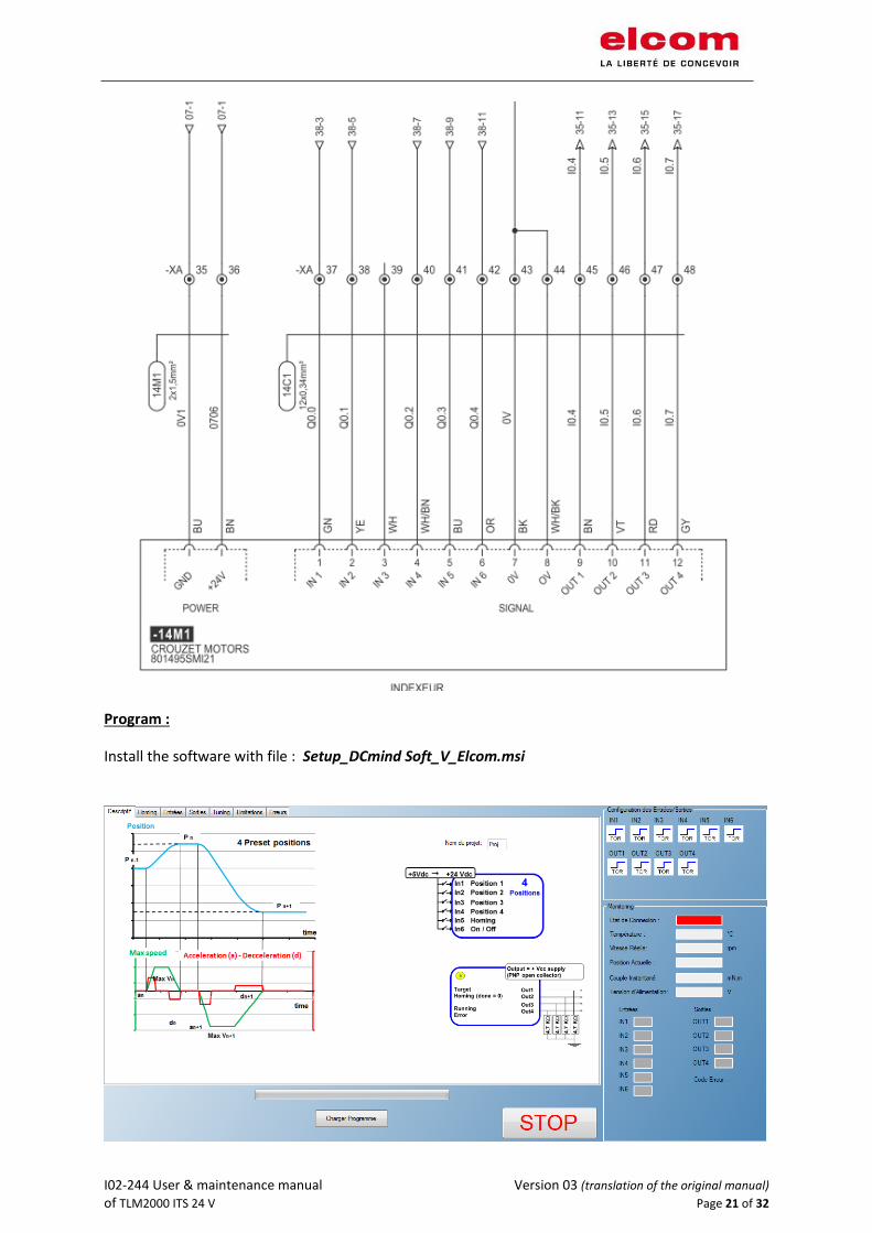
Program :
Install the software with file : Setup_DCmind Soft_V_Elcom.msi

I02-244 User & maintenance manual Version 03 (translation of the original manual) of TLM2000 ITS 24 V Page 22 of 32

I02-244 User & maintenance manual Version 03 (translation of the original manual) of TLM2000 ITS 24 V Page 23 of 32
I02-244 User & maintenance manual Version 03 (translation of the original manual) of TLM2000 ITS 24 V Page 24 of 32
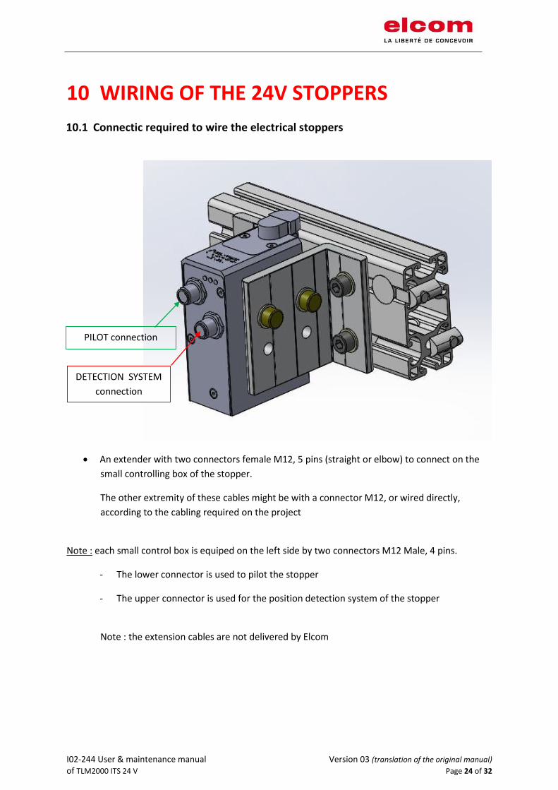
10 WIRING OF THE 24V STOPPERS
10.1 Connectic required to wire the electrical stoppers
• An extender with two connectors female M12, 5 pins (straight or elbow) to connect on the
small controlling box of the stopper.
The other extremity of these cables might be with a connector M12, or wired directly,
according to the cabling required on the project
Note : each small control box is equiped on the left side by two connectors M12 Male, 4 pins.
- The lower connector is used to pilot the stopper
- The upper connector is used for the position detection system of the stopper
Note : the extension cables are not delivered by Elcom
PILOT connection
DETECTION SYSTEM
connection

I02-244 User & maintenance manual Version 03 (translation of the original manual) of TLM2000 ITS 24 V Page 25 of 32
10.2 Wiring of the control box of the stoppers
Two connecteur M12 / 5 poles :
PILOT connection
PILOTAGE
DETECTION SYSTEM
connection
I02-244 User & maintenance manual Version 03 (translation of the original manual) of TLM2000 ITS 24 V Page 26 of 32
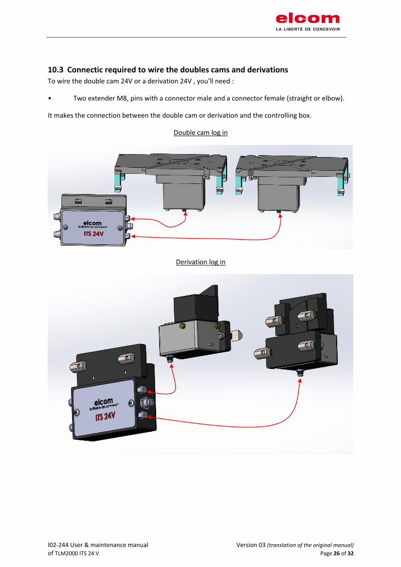
10.3 Connectic required to wire the doubles cams and derivations
To wire the double cam 24V or a derivation 24V , you’ll need :
• Two extender M8, pins with a connector male and a connector female (straight or elbow).
It makes the connection between the double cam or derivation and the controlling box.
Double cam log in
Derivation log in

I02-244 User & maintenance manual Version 03 (translation of the original manual) of TLM2000 ITS 24 V Page 27 of 32
• An extender with a connector female M12, 4 pins (straight or elbow) to connect on the small
controlling box of the stopper.
The other extremity of this cable might be with a connector M12, or wired directly, according to the
cabling required on the project
Note : each small control box is equiped on the left side by two connectors M12 Male, 4 pins.
The lower connector is to control the stopper by an automat (PLC)
The upper connector is to control the stopper by a bus (BUS)
Note : the extension cables are not delivered by Elcom
Wiring PLC
Wiring BUS Motor
Wiring 1
Motor
Wiring 2
I02-244 User & maintenance manual Version 03 (translation of the original manual) of TLM2000 ITS 24 V Page 28 of 32
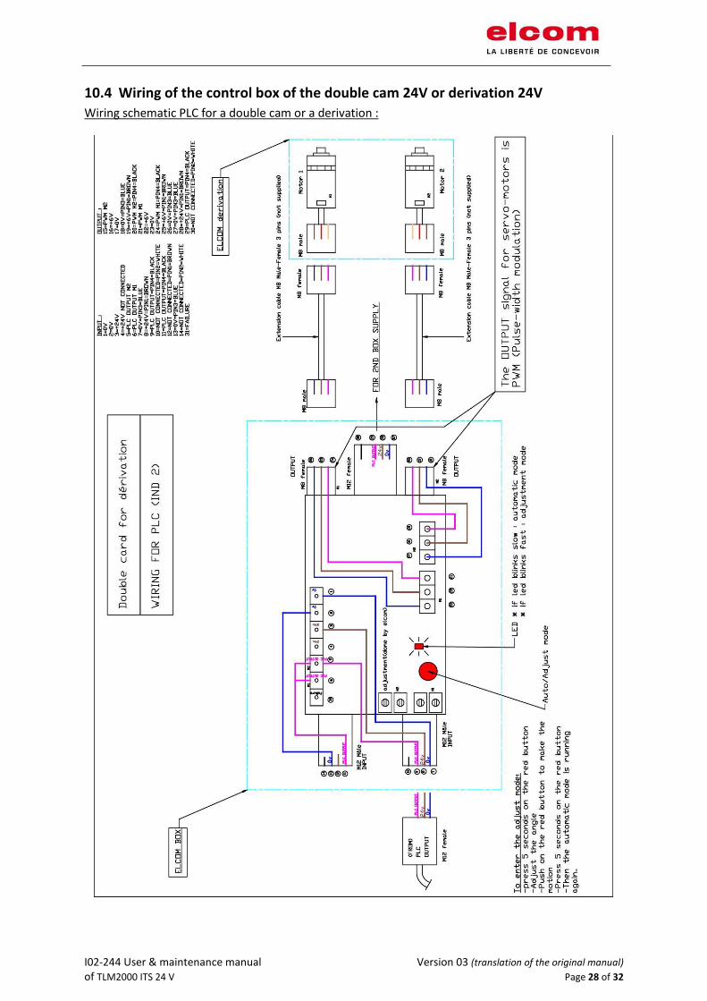
10.4 Wiring of the control box of the double cam 24V or derivation 24V
Wiring schematic PLC for a double cam or a derivation :
I02-244 User & maintenance manual Version 03 (translation of the original manual) of TLM2000 ITS 24 V Page 29 of 32
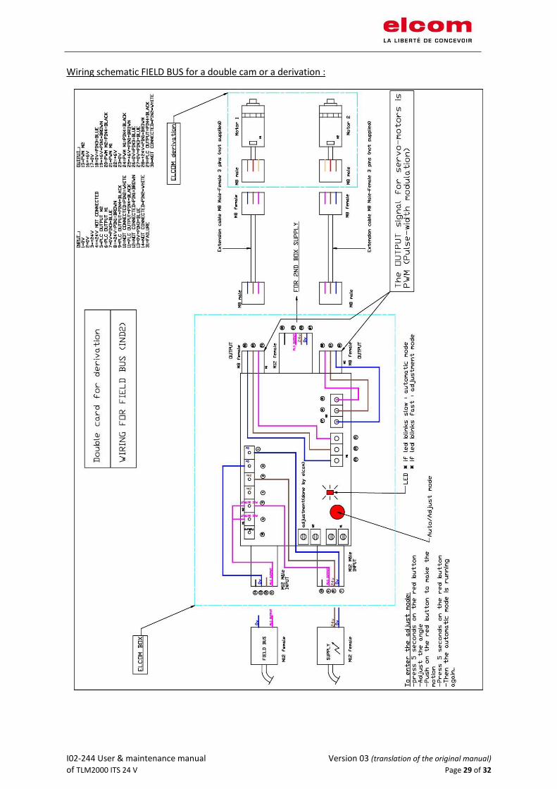
Wiring schematic FIELD BUS for a double cam or a derivation :

I02-244 User & maintenance manual Version 03 (translation of the original manual) of TLM2000 ITS 24 V Page 30 of 32
11 RESPONSABILITY Elcom cannot be held responsible for any damages or harms due to non-authorized modification of
any parts, especially the safety parts.
Only original components can be used for maintenance or fixing.
Elcom cannot be held responsible for any malfunction if some spare parts have been used without
the validation of elcom.
Elcom reserves the right to make improvements and technical modifications without any further
notice.
12 CUSTOMER SERVICE Do not hesitate to contact us for any question or advice. We will be glad to assist you:
Téléphone : + 33 (0)4 74 43 99 61
Email : [email protected]
Address: 1 rue Isaac Asimov
ZAC de la Maladière
38300 Bourgoin-Jallieu
Before any contact, please note down the serial number of the transfer system. This number can be
found on the transfer system sticker, like the following example.

I02-244 User & maintenance manual Version 03 (translation of the original manual) of TLM2000 ITS 24 V Page 31 of 32
13 APPENDIX
13.1 Maintenance schedule
Maintenance of the modular transfer system TLM 2000 ITS 24V
Frequency Action Component Chapter
200 hours Dusting Transfer system elements 4.5
500 hours Control Belts – Belt guide – Workpiece carrier 4.1
1000 hours Clean and lubricate
Positioning unit 4.7
5000 hours Clean Double Cams 4.8
5000 hours Clean Derivations 4.9
5000 hours Clean Stoppers 4.10

I02-244 User & maintenance manual Version 03 (translation of the original manual) of TLM2000 ITS 24 V Page 32 of 32
13.2 Quality and environmental commitment: ISO certifications
Our company is recognized according to the following ISO standards and their respective evolutions
since our first certification:
- Quality Management through ISO 9001 [since 2002]
- Environmental Management through ISO 14001 [since 2013]
All our current certificates are available for download in French, English and German on our website
http://elcom-automation.com/