Embed Size (px)
Citation preview
on DEMAND®
SIMULTANEOUS HEATING AND COOLING• •
Application GuideModular Chiller Products

1www.climacoolcorp.com
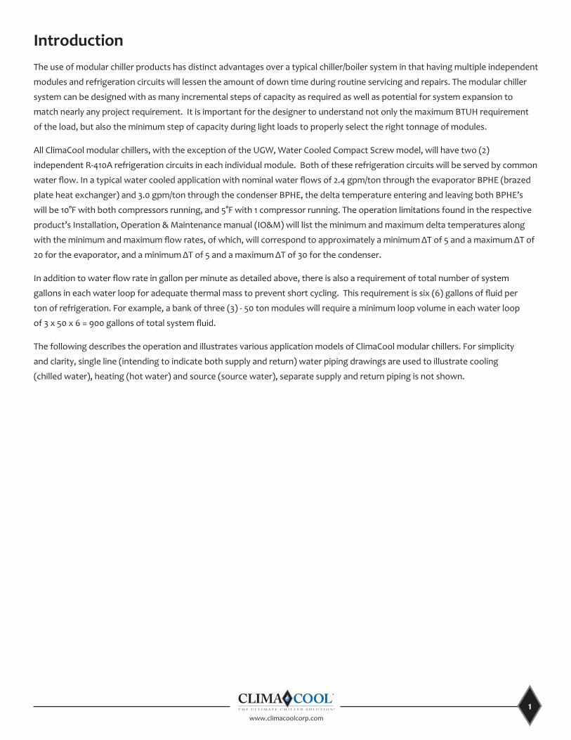
IntroductionThe use of modular chiller products has distinct advantages over a typical chiller/boiler system in that having multiple independent
modules and refrigeration circuits will lessen the amount of down time during routine servicing and repairs. The modular chiller
system can be designed with as many incremental steps of capacity as required as well as potential for system expansion to
match nearly any project requirement. It is important for the designer to understand not only the maximum BTUH requirement
of the load, but also the minimum step of capacity during light loads to properly select the right tonnage of modules.
All ClimaCool modular chillers, with the exception of the UGW, Water Cooled Compact Screw model, will have two (2)
independent R-410A refrigeration circuits in each individual module. Both of these refrigeration circuits will be served by common
water flow. In a typical water cooled application with nominal water flows of 2.4 gpm/ton through the evaporator BPHE (brazed
plate heat exchanger) and 3.0 gpm/ton through the condenser BPHE, the delta temperature entering and leaving both BPHE’s
will be 10°F with both compressors running, and 5°F with 1 compressor running. The operation limitations found in the respective
product’s Installation, Operation & Maintenance manual (IO&M) will list the minimum and maximum delta temperatures along
with the minimum and maximum flow rates, of which, will correspond to approximately a minimum ΔT of 5 and a maximum ΔT of
20 for the evaporator, and a minimum ΔT of 5 and a maximum ΔT of 30 for the condenser.
In addition to water flow rate in gallon per minute as detailed above, there is also a requirement of total number of system
gallons in each water loop for adequate thermal mass to prevent short cycling. This requirement is six (6) gallons of fluid per
ton of refrigeration. For example, a bank of three (3) - 50 ton modules will require a minimum loop volume in each water loop
of 3 x 50 x 6 = 900 gallons of total system fluid.
The following describes the operation and illustrates various application models of ClimaCool modular chillers. For simplicity
and clarity, single line (intending to indicate both supply and return) water piping drawings are used to illustrate cooling
(chilled water), heating (hot water) and source (source water), separate supply and return piping is not shown.
www.climacoolcorp.com
2
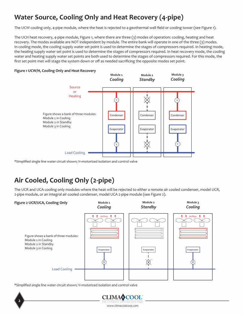
Water Source, Cooling Only and Heat Recovery (4-pipe) The UCW cooling only, 4-pipe module, where the heat is rejected to a geothermal well field or cooling tower (see Figure 1).
The UCH heat recovery, 4-pipe module, Figure 1, where there are three (3) modes of operation: cooling, heating and heat recovery. The modes available are NOT independent by module. The entire bank will operate in one of the three (3) modes. In cooling mode, the cooling supply water set point is used to determine the stages of compressors required. In heating mode, the heating supply water set point is used to determine the stages of compressors required. In heat recovery mode, the cooling water and heating supply water set points are both used to determine the stages of compressors required. For this mode, the first set point met will stage the system down or off as needed sacrificing the opposite modes set point.
Figure 1 UCW/H, Cooling Only and Heat Recovery
*Simplified single line water circuit shown; V=motorized isolation and control valve
Air Cooled, Cooling Only (2-pipe) The UCR and UCA cooling only modules where the heat will be rejected to either a remote air cooled condenser, model UCR, 2-pipe module, or an integral air cooled condenser, model UCA 2-pipe module (see Figure 2).
Figure 2 UCR/UCA, Cooling Only
*Simplified single line water circuit shown; V=motorized isolation and control valve
Module 3
Cooling
V
Evaporator
Airflow
UCA/UCR COOLING ONLY BANK LAYOUT
This document is the sole property of ClimaCool Corp. Distribution of this document is forbidden without the
written consent of ClimaCool Corp. Design changes to any portion of this document may occur without notice.
CHILLER LAYOUT: Cooling Only Bank Layout
PROJECT:
CC P/N's: UCA020, UCA030, UCA070, UCR030, UCR050, UCR070
SIZE DGW. NO.UCA/UCR COOLING ONLY BANK LAYOUT
SCALE: NONE DATE: 03/07/14 SHEET: 1 of 1 REV. A
Load Cooling
Module 1
Cooling
V
Evaporator
V
Evaporator
Module 2
Standby
Airflow
* Simplified single line water circuit shown; V=motorized isolation and control valve
Figure shows a bank of three modules:Module 1 in CoolingModule 2 in StandbyModule 3 in Cooling
Evaporator
Sourceor
Heating
Load Cooling
V
CondenserCondenser
V
Evaporator
V
Condenser
Evaporator
V V
V
This document is the sole property of ClimaCool Corp. Distribution of this document is forbidden without the
written consent of ClimaCool Corp. Design changes to any portion of this document may occur without notice.
CHILLER LAYOUT: UCW/H BANK - COOLING ONLY & HEAT RECOVERY
PROJECT:
CC P/N's: UCW/H
SIZE DGW. NO.UCW/H BANK - COOLING ONLY & HEAT RECOVERY
SCALE: NONE DATE: 03/07/14 SHEET: 1 of 1 REV. A
Module 1
CoolingModule 3
CoolingModule 2
Standby
* Simplified single line water circuit shown; V=motorized isolation and control valve
Figure shows a bank of three modules:Module 1 in CoolingModule 2 in StandbyModule 3 in Cooling
UCW/H BANK - COOLING ONLY & HEAT RECOVERY
3www.climacoolcorp.com
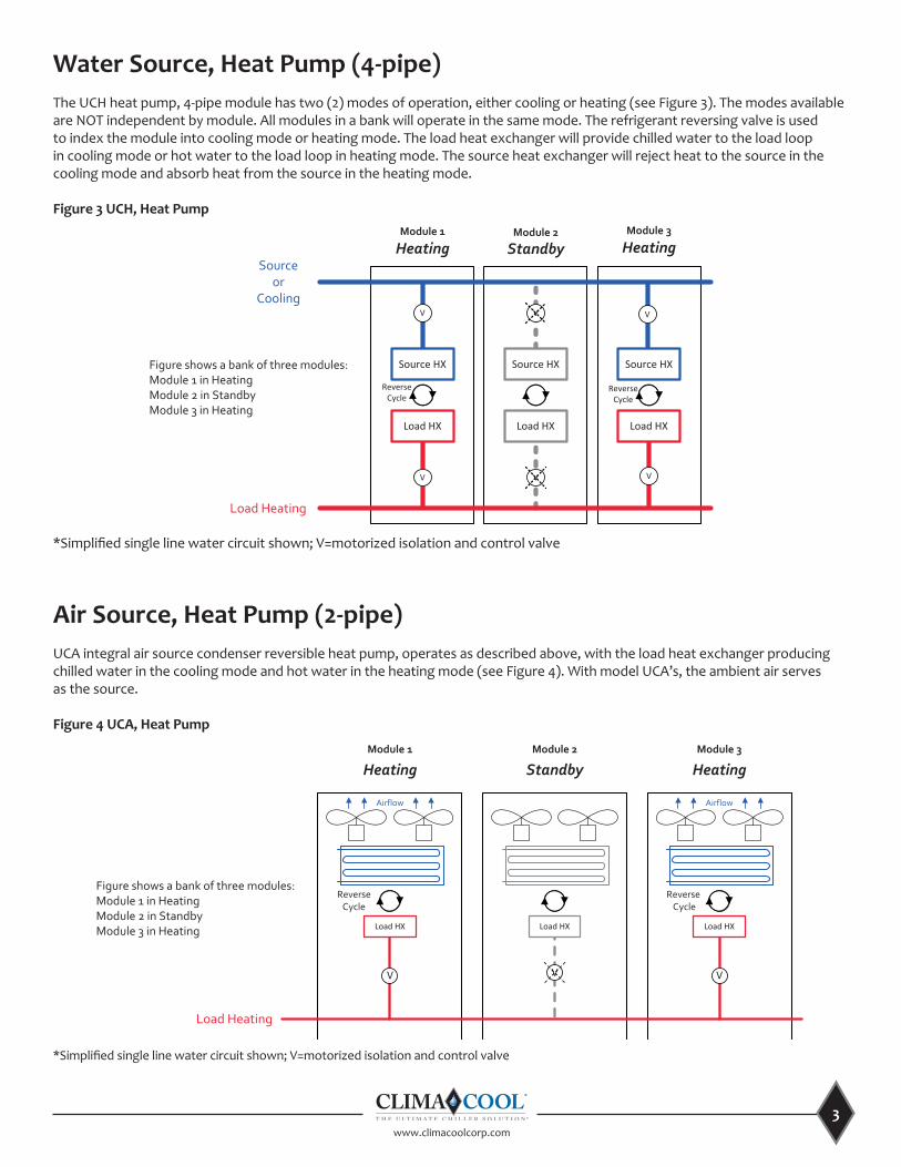
Water Source, Heat Pump (4-pipe) The UCH heat pump, 4-pipe module has two (2) modes of operation, either cooling or heating (see Figure 3). The modes available are NOT independent by module. All modules in a bank will operate in the same mode. The refrigerant reversing valve is used to index the module into cooling mode or heating mode. The load heat exchanger will provide chilled water to the load loop in cooling mode or hot water to the load loop in heating mode. The source heat exchanger will reject heat to the source in the cooling mode and absorb heat from the source in the heating mode.
Figure 3 UCH, Heat Pump
Air Source, Heat Pump (2-pipe) UCA integral air source condenser reversible heat pump, operates as described above, with the load heat exchanger producing chilled water in the cooling mode and hot water in the heating mode (see Figure 4). With model UCA’s, the ambient air serves as the source.
Figure 4 UCA, Heat Pump
*Simplified single line water circuit shown; V=motorized isolation and control valve
*Simplified single line water circuit shown; V=motorized isolation and control valve
This document is the sole property of ClimaCool Corp. Distribution of this document is forbidden without the
written consent of ClimaCool Corp. Design changes to any portion of this document may occur without notice.
CHILLER LAYOUT: UCH HEAT PUMP BANK – HEATING MODE
PROJECT:
CC P/N's: UCH HP
SIZE DGW. NO.UCH HEATPUMP BANK-HEATING MODE
SCALE: NONE DATE: 05/13/14 SHEET: 1 of 1 REV. B
Source or
Cooling
Load Heating
V
Source HXSource HX
V
Load HX
V
Source HX
Load HX
V V
V
* Simplified single line water circuit shown; V=motorized isolation and control valve
Figure shows a bank of three modules:Module 1 in HeatingModule 2 in StandbyModule 3 in Heating
UCH HEAT PUMP BANK – HEATING MODE
Load HX
ReverseCycle
Module 1
HeatingModule 3
HeatingModule 2
Standby
ReverseCycle
This document is the sole property of ClimaCool Corp. Distribution of this document is forbidden without the
written consent of ClimaCool Corp. Design changes to any portion of this document may occur without notice.
CHILLER LAYOUT: UCA HEAT PUMP BANK – HEATING MODE
PROJECT:
CC P/N's: UCA020, UCA030, UCA070
SIZE DGW. NO.UCA HEATPUMP BANK-HEATING MODE
SCALE: NONE DATE: 05/13/14 SHEET: 1 of 1 REV. B
UCA HEAT PUMP BANK – HEATING MODE
Load Heating
Module 1
Heating
V
Load HX
V
Load HX
Module 2
StandbyModule 3
Heating
Airflow
* Simplified single line water circuit shown; V=motorized isolation and control valve
Figure shows a bank of three modules:Module 1 in HeatingModule 2 in StandbyModule 3 in Heating
V
Load HX
Airflow
ReverseCycle
ReverseCycle
www.climacoolcorp.com
4
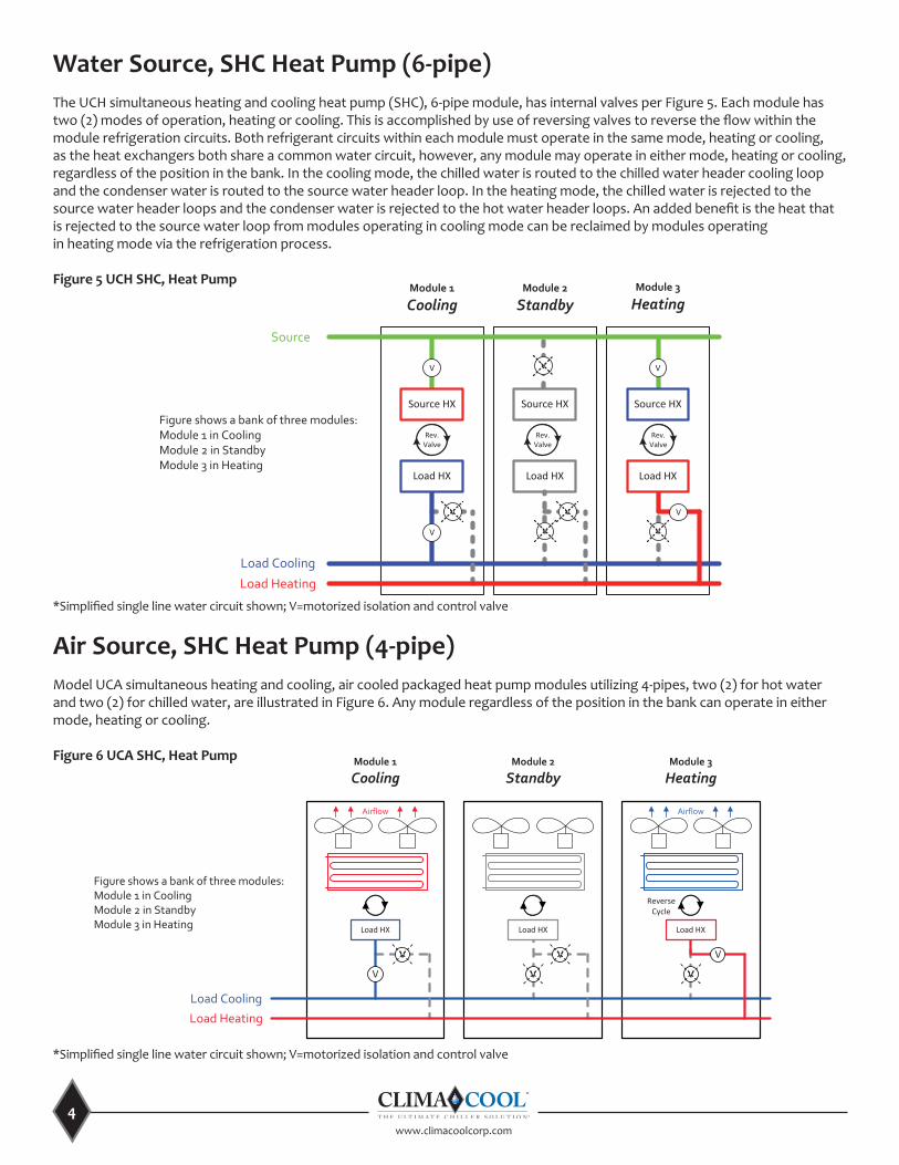
Water Source, SHC Heat Pump (6-pipe) The UCH simultaneous heating and cooling heat pump (SHC), 6-pipe module, has internal valves per Figure 5. Each module has two (2) modes of operation, heating or cooling. This is accomplished by use of reversing valves to reverse the flow within the module refrigeration circuits. Both refrigerant circuits within each module must operate in the same mode, heating or cooling, as the heat exchangers both share a common water circuit, however, any module may operate in either mode, heating or cooling, regardless of the position in the bank. In the cooling mode, the chilled water is routed to the chilled water header cooling loop and the condenser water is routed to the source water header loop. In the heating mode, the chilled water is rejected to the source water header loops and the condenser water is rejected to the hot water header loops. An added benefit is the heat that is rejected to the source water loop from modules operating in cooling mode can be reclaimed by modules operating in heating mode via the refrigeration process.
Figure 5 UCH SHC, Heat Pump
This document is the sole property of ClimaCool Corp. Distribution of this document is forbidden without the
written consent of ClimaCool Corp. Design changes to any portion of this document may occur without notice.
CHILLER LAYOUT: UCH SHC-HP BANK
PROJECT:
CC P/N's: UCH SHC-HP
SIZE DGW. NO.UCH SHC-HP BANK
SCALE: NONE DATE: 03/07/14 SHEET: 1 of 1 REV. A
* Simplified single line water circuit shown; V=motorized isolation and control valve
UCH SHC-HP BANK
Load HX
V
V V
V
Source HX
V
Load HX
V
Source HX
Rev.Valve
Load HX
V
Source HX
V
V
Source
Load Cooling
Module 1
CoolingModule 3
HeatingModule 2
Standby
Figure shows a bank of three modules:Module 1 in CoolingModule 2 in StandbyModule 3 in Heating
Load Heating
Rev.Valve
Rev.Valve
Air Source, SHC Heat Pump (4-pipe) Model UCA simultaneous heating and cooling, air cooled packaged heat pump modules utilizing 4-pipes, two (2) for hot water and two (2) for chilled water, are illustrated in Figure 6. Any module regardless of the position in the bank can operate in either mode, heating or cooling.
Figure 6 UCA SHC, Heat Pump
*Simplified single line water circuit shown; V=motorized isolation and control valve
*Simplified single line water circuit shown; V=motorized isolation and control valve
UCA SHC - INTEGRAL 4 HEADER SIMULTANEOUS HEATING & COOLING HEAT PUMP BANK LAYOUT
This document is the sole property of ClimaCool Corp. Distribution of this document is forbidden without the
written consent of ClimaCool Corp. Design changes to any portion of this document may occur without notice.
CHILLER LAYOUT: SIMULTANEOUS HTG & CLG HEAT PUMP BANK
PROJECT: UCA SHC - INTEGRAL 4 HEADER SIMULTANEOUS HEATING & COOLING HEAT PUMP BANK LAYOUT
CC P/N's: UCA020, UCA030, UCA070
SIZE DGW. NO.UCA SHC - INTEGRAL 4 HEADER SIMULTANEOUS HEATING & COOLING HEAT PUMP BANK LAYOUT
SCALE: NONE DATE: 05/13/2014 SHEET: 1 of 1 REV. C
Load Cooling
Load Heating
Module 1
Cooling
V
V
Load HX
V
V
Load HX
V
V
Load HX
Module 2
StandbyModule 3
Heating
Airflow Airflow
* Simplified single line water circuit shown; V=motorized isolation and control valve
Figure shows a bank of three modules:Module 1 in CoolingModule 2 in StandbyModule 3 in Heating
ReverseCycle
5www.climacoolcorp.com
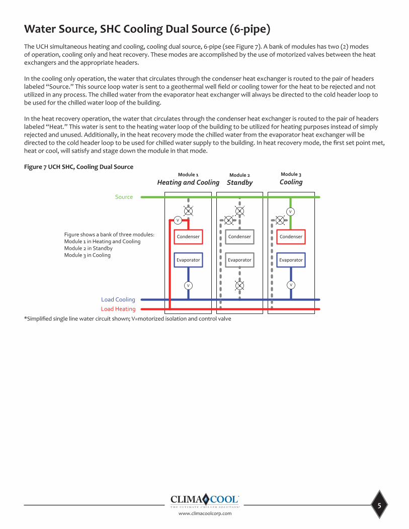
Water Source, SHC Cooling Dual Source (6-pipe) The UCH simultaneous heating and cooling, cooling dual source, 6-pipe (see Figure 7). A bank of modules has two (2) modes of operation, cooling only and heat recovery. These modes are accomplished by the use of motorized valves between the heat exchangers and the appropriate headers.
In the cooling only operation, the water that circulates through the condenser heat exchanger is routed to the pair of headers labeled “Source.” This source loop water is sent to a geothermal well field or cooling tower for the heat to be rejected and not utilized in any process. The chilled water from the evaporator heat exchanger will always be directed to the cold header loop to be used for the chilled water loop of the building.
In the heat recovery operation, the water that circulates through the condenser heat exchanger is routed to the pair of headers labeled “Heat.” This water is sent to the heating water loop of the building to be utilized for heating purposes instead of simply rejected and unused. Additionally, in the heat recovery mode the chilled water from the evaporator heat exchanger will be directed to the cold header loop to be used for chilled water supply to the building. In heat recovery mode, the first set point met, heat or cool, will satisfy and stage down the module in that mode.
Figure 7 UCH SHC, Cooling Dual Source
Evaporator
Source
Load Cooling
V
Condenser
Evaporator
V
Condenser
Evaporator
V V
This document is the sole property of ClimaCool Corp. Distribution of this document is forbidden without the
written consent of ClimaCool Corp. Design changes to any portion of this document may occur without notice.
CHILLER LAYOUT: UCH SHC BANK - COOLING PRIORITY
PROJECT:
CC P/N's: UCH SHC
SIZE DGW. NO.UCH SHC BANK - COOLING PRIORITY
SCALE: NONE DATE: 03/07/14 SHEET: 1 of 1 REV. A
Module 1
Heating and CoolingModule 3
CoolingModule 2
Standby
* Simplified single line water circuit shown; V=motorized isolation and control valve
Figure shows a bank of three modules:Module 1 in Heating and CoolingModule 2 in StandbyModule 3 in Cooling
UCH SHC BANK - COOLING PRIORITY
Load Heating
VV
V
Condenser
VV
*Simplified single line water circuit shown; V=motorized isolation and control valve
www.climacoolcorp.com
6
Evaporator
Source
Load Cooling
Condenser
This document is the sole property of ClimaCool Corp. Distribution of this document is forbidden without the
written consent of ClimaCool Corp. Design changes to any portion of this document may occur without notice.
CHILLER LAYOUT: UCH SHC BANK - HEATING PRIORITY
PROJECT:
CC P/N's: UCH SHC
SIZE DGW. NO.UCH SHC BANK - HEATING PRIORITY
SCALE: NONE DATE: 03/07/14 SHEET: 1 of 1 REV. A
Module 1
Heating and CoolingModule 3
HeatingModule 2
Standby
* Simplified single line water circuit shown; V=motorized isolation and control valve
Figure shows a bank of three modules:Module 1 in Heating and CoolingModule 2 in StandbyModule 3 in Heating
UCH SHC BANK - HEATING PRIORITY
Load Heating
V
V V
Evaporator
Condenser
V
Condenser
Evaporator
V V
V V V
*Simplified single line water circuit shown; V=motorized isolation and control valve
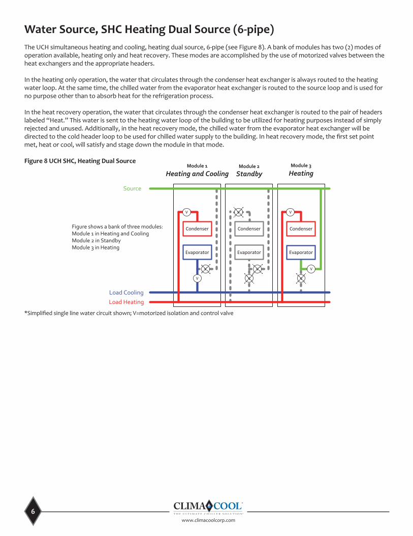
Water Source, SHC Heating Dual Source (6-pipe) The UCH simultaneous heating and cooling, heating dual source, 6-pipe (see Figure 8). A bank of modules has two (2) modes of operation available, heating only and heat recovery. These modes are accomplished by the use of motorized valves between the heat exchangers and the appropriate headers.
In the heating only operation, the water that circulates through the condenser heat exchanger is always routed to the heating water loop. At the same time, the chilled water from the evaporator heat exchanger is routed to the source loop and is used for no purpose other than to absorb heat for the refrigeration process.
In the heat recovery operation, the water that circulates through the condenser heat exchanger is routed to the pair of headers labeled “Heat.” This water is sent to the heating water loop of the building to be utilized for heating purposes instead of simply rejected and unused. Additionally, in the heat recovery mode, the chilled water from the evaporator heat exchanger will be directed to the cold header loop to be used for chilled water supply to the building. In heat recovery mode, the first set point met, heat or cool, will satisfy and stage down the module in that mode.
Figure 8 UCH SHC, Heating Dual Source
7www.climacoolcorp.com
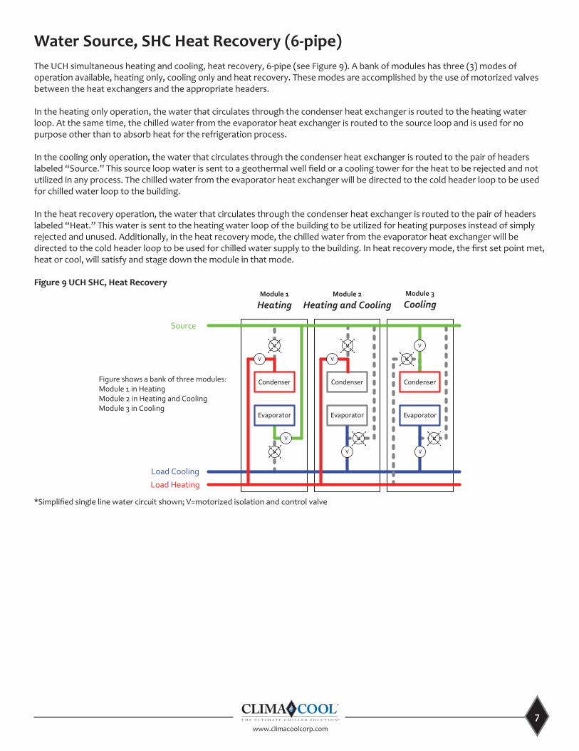
Water Source, SHC Heat Recovery (6-pipe) The UCH simultaneous heating and cooling, heat recovery, 6-pipe (see Figure 9). A bank of modules has three (3) modes of operation available, heating only, cooling only and heat recovery. These modes are accomplished by the use of motorized valves between the heat exchangers and the appropriate headers.
In the heating only operation, the water that circulates through the condenser heat exchanger is routed to the heating water loop. At the same time, the chilled water from the evaporator heat exchanger is routed to the source loop and is used for no purpose other than to absorb heat for the refrigeration process.
In the cooling only operation, the water that circulates through the condenser heat exchanger is routed to the pair of headers labeled “Source.” This source loop water is sent to a geothermal well field or a cooling tower for the heat to be rejected and not utilized in any process. The chilled water from the evaporator heat exchanger will be directed to the cold header loop to be used for chilled water loop to the building.
In the heat recovery operation, the water that circulates through the condenser heat exchanger is routed to the pair of headers labeled “Heat.” This water is sent to the heating water loop of the building to be utilized for heating purposes instead of simply rejected and unused. Additionally, in the heat recovery mode, the chilled water from the evaporator heat exchanger will be directed to the cold header loop to be used for chilled water supply to the building. In heat recovery mode, the first set point met, heat or cool, will satisfy and stage down the module in that mode.
Figure 9 UCH SHC, Heat Recovery
Source
Load Cooling
Condenser
This document is the sole property of ClimaCool Corp. Distribution of this document is forbidden without the
written consent of ClimaCool Corp. Design changes to any portion of this document may occur without notice.
CHILLER LAYOUT: UCH SHC-HR BANK
PROJECT:
CC P/N's: UCH SHC-HR
SIZE DGW. NO.UCH SHC-RH BANK
SCALE: NONE DATE: 03/07/14 SHEET: 1 of 1 REV. A
Module 1
HeatingModule 3
CoolingModule 2
Heating and Cooling
* Simplified single line water circuit shown; V=motorized isolation and control valve
Figure shows a bank of three modules:Module 1 in HeatingModule 2 in Heating and CoolingModule 3 in Cooling
UCH SHC-HR BANK
Load Heating
V V
Evaporator
Condenser
Evaporator
V V V
Condenser
V
V
V
V
V
V
V
Evaporator
*Simplified single line water circuit shown; V=motorized isolation and control valve
www.climacoolcorp.com
8
Operational Envelope
A maximum delta T of 100°F is allowed between leaving load temperature and leaving source temperature for all products, as well as leaving load heating temperature and leaving load cooling temperature for simultaneous heating and cooling heat recovery products. Example: if using glycol and a chilled water temperature of 25°F, the maximum source water temperature would be 125°F.
If the source loop has the potential to drop below this 100°F differential temperature limit, either lower the hot water set point accordingly or provide a supplemental heat source to the source loop.
Motorized Valves
ClimaCool modular chiller banks can be provided with or without motorized valves at each module. When provided without motorized valves, it is essential to use equal circuit loading in which one compressor in each module will incrementally start and run before the second compressor in each module is called to run. The staging order for a bank without motorized valves will be M1C1, M2C1, M3C1 and M4C1, where “M” indicates is the module number and “C” indicates the compressor/circuit number. This allows all the heat exchangers to become active minimizing the amount of unconditioned bypass water that will affect the resulting supply chilled water temperature.
When modules are provided with motorized valves, staged circuit loading is utilized, in which each module starts both compressor one (1) and two (2) before the next module is indexed to run. The staging order for a motorized valve bank will be M1C1, M1C2, M2C1, M2C2, M3C1 and M3C2. As each module is indexed to operate, the motorized valves will open. Once the mechanical end switches of both the load and source valves electrically close, the compressor will be allowed to operate.
ClimaCool utilizes two (2) types of motorized valves. The first type is an ON/OFF valve and the second is a proportional valve. On a standard UCW, 4-pipe, cooling only module with motorized valves, the evaporator (load) motorized valve will open to 100%. The end switch is field adjusted to electrically close at approximately 25% to 30% of the valve opening position allowing the compressor to start. The condenser (source) motorized valve is a proportional type of which has a signal input range of 2.0 to 10 vdc, 2.0 vdc being closed and 10 vdc being 100% open. ClimaCool uses a default minimum position of 3.6 vdc, adjustable, for the condenser (source) proportional motorized valve. This is for the purpose of refrigerant head pressure control when the entering condenser water temperature is low. When the module is indexed to operate and the valves are commanded to open, the evaporator motorized valve will open to 100%, as described above and the condenser motorized valve will open to its minimum position. All proportional valves that are used with a minimum position must have the actuator end switch adjusted so contact closure is ensured at the minimum voltage position or the compressor will not start. It is possible to increase the minimum position voltage but at the expense of modulation range for refrigerant head pressure control. The typical refrigerant head pressure target is 265 psig. Above this pressure the motorized valve will be at 100% open, below this pressure the valve will modulate to maintain the target pressure.
All simultaneous heating and cooling (SHC) designed modules also incorporate proportional motorized valves for the purpose of load limiting. Under certain mode changeover conditions the active evaporator heat exchanger may experience a heavily loaded water loop in which high refrigerant suction pressures will result. The high suction pressure set point is set for 150 psig. When the suction pressure exceeds this value, one motorized valve for the SHC heat pump or both motorized valves for the SHC heat recovery will modulate from fully open towards closed to maintain the suction pressure at or near set point. This helps to prevent operation of the compressor outside its design envelope.
9www.climacoolcorp.com
The operation of each header bypass pertains only to the loop on which it is installed. Taken on a loop by loop basis, the CoolLogic Controller monitors all the motorized valve end switches within each of the modules that connect to that loop for that mode of operation. Example: the load cooling loop has motorized valves connected to the load heat exchangers. When no module has motorized valves open to the load cooling loop, all of those motorized end switches will be electrically open. The CoolLogic Controller recognizes this and signals the header bypass valve to open, allowing flow through the header bypass. Once the first module is indexed to cooling mode and both motorized valves mechanically open (end switches electrically close), the header bypass valve is signaled to mechanically close, as the module that was indexed to cool mode now provides the water flow path.
Modules can also be assigned for fixed bypass for heating, cooling and source flow, however, this limits the number of modules remaining for that duty. For example with an SHC OnDemand heat pump system with four (4) modules, if one (1) module is designated for heating bypass and one (1) module for cooling bypass, the system now only allows a maximum of three (3) modules for heating or three (3) modules for cooling.
Anytime the system bank of modules is enabled, and no internal module valves have opened yet, the external bypass, or internal fixed module, valves will be open, allowing the minimum flow to prevent pump dead-heading and allow accurate sensing of the loop water. Once the first module is indexed to operate and the internal motorized valve begins to open, the electrical closure of the auxiliary end switch will trigger the CoolLogic Controller to close the external bypass valve, or internal fixed module valve(s), as they are no longer needed for the purpose above.
In the simultaneous heat pump and heat recovery models, the fixed module can be used, but now there is more than one mode of operation. This requires one (1) module to be fixed in cool and a second module to be fixed in heat. The cooling mode of operation only uses the cool loop and the source loop and the heat mode only uses the heat loop and the source loop. Fixing only one (1) module in a mode will only allow the minimum internal flow bypass in only two (2) of the three (3) loops. This is why two (2) modules need to be fixed in opposite modes. If four (4) modules are installed in a bank and module one (1) is fixed in cool and module two (2) is fixed in heat, modules three (3) and four (4) will be open available for either mode as the cooling or heating demand dictates. Using this method, there can only be three (3) modules available for cool or three (3) modules available for heat. It is strongly recommended to utilize the external bypasses over the fixed module method so that all modules in a bank always will be available for any mode of operation.
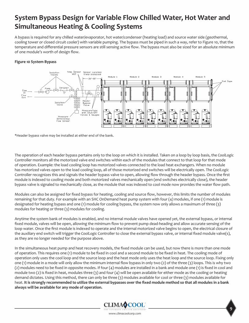
System Bypass Design for Variable Flow Chilled Water, Hot Water and Simultaneous Heating & Cooling SystemsA bypass is required for any chilled water/evaporator, hot water/condenser (heating load) and source water side (geothermal, cooling tower or closed circuit cooler) with variable pumping. The bypass must be piped in such a way, refer to Figure 10, that the temperature and differential pressure sensors are still sensing active flow. The bypass must also be sized for an absolute minimum of one module’s worth of design flow.
Figure 10 System Bypass
*Header bypass valve may be installed at either end of the bank.
www.climacoolcorp.com
10
Variable Primary Pump Systems (Pump Control)
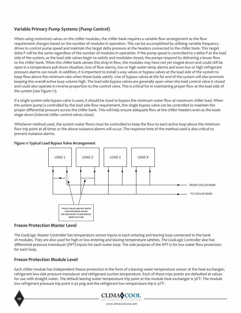
When using motorized valves on the chiller modules, the chiller bank requires a variable flow arrangement as the flow requirement changes based on the number of modules in operation. This can be accomplished by utilizing variable frequency drives to control pump speed and maintain the target delta pressure at the headers connected to the chiller bank. This target delta P will be the same regardless of the number of modules in operation. If the pump speed is controlled to a delta P at the load side of the system, as the load side valves begin to satisfy and modulate closed, the pumps respond by delivering a lesser flow to the chiller bank. When the chiller bank senses this drop in flow, the modules may have not yet staged down and could still be open in a temperature pull down situation, loss of flow alarms, low or high water temp alarms and even low or high refrigerant pressure alarms can result. In addition, it is important to install 3-way valves or bypass valves at the load side of the system to keep flow above the minimum rate when these loads satisfy. Use of bypass valves at the far end of the system will also promote keeping the overall active loop volume high. The load side bypass valves are generally open when the load control valve is closed and could also operate in reverse proportion to the control valve. This is critical for in maintaining proper flow at the load side of the system (see Figure 11).
If a single system side bypass valve is used, it should be sized to bypass the minimum water flow at maximum chiller load. When the system pump is controlled by the load side flow requirement, this single bypass valve can be controlled to maintain the proper differential pressure across the chiller bank. This will help ensure adequate flow at the chiller headers even as the loads stage down (internal chiller control valves close).
Whichever method used, the system water flows must be controlled to keep the flow to each active loop above the minimum flow trip point at all times or the above nuisance alarms will occur. The response time of the method used is also critical to prevent nuisance alarms.
Figure 11 Typical Load Bypass Valve Arrangement
LOAD 1
FROM CHILLER BANK
TYPICAL LOAD BYPASS VALVE ARRANGEMENT
TO CHILLER BANK
LOAD 2 LOAD 3 LOAD X
TYPICAL CHILLED AND HOT WATER LOAD SIDE BYPASS VALVES
SIZE EQUIVALENT TO ONE MODULE WORTH OF FLOW
Freeze Protection Master Level
The CoolLogic Master Controller has temperature sensor inputs in each entering and leaving loop connected to the bank of modules. They are also used for high or low entering and leaving temperature safeties. The CoolLogic Controller also has differential pressure transducer (DPT) inputs for each water loop. The sole purpose of the DPT is for low water flow protection for each loop.
Freeze Protection Module Level
Each chiller module has independent freeze protection in the form of a leaving water temperature sensor at the heat exchanger, refrigerant low-side pressure transducer and refrigerant suction temperature. Each of these trips points are defaulted at values for use with straight water. The default leaving water temperature trip point at the module heat exchanger is 36°F. The module low refrigerant pressure trip point is 92 psig and the refrigerant low temperature trip is 32°F.
11www.climacoolcorp.com
Glycol Usage
If glycol is used in a specific loop and these settings require adjustment, care must be taken to first confirm the type and percentage of glycol used in the loop. The ClimaCool Installation, Operation & Maintenance Manual (IO&M), containing the freeze chart for propylene and ethylene glycol, can be reviewed to determine the actual freeze point with the confirmed concentration.
ClimaCool recommends the module freeze temperature setting be adjusted no less than 8°F above the actual freeze point of the solution. The coincidental refrigerant low pressure and temperature trip points will also require adjustment in accordance with this value using a 5°F to 6°F approach temperature. For example, 30% propylene glycol has been confirmed to be present in a chilled water loop. The freeze point of this solution is 9°F. So the module leaving water freeze point should be set to 17°F, (9°F + 8°F = 17°F). Using the approach of 5°F the refrigerant temperature at this leaving water temperature is 12°F. Using a pressure temperature chart, the coincidental refrigerant pressure is approximately 65 psig. The low suction temperature trip point should also be adjusted to the minimum superheat above the adjusted saturated suction temperature. In the example above, the saturated temperature was 12°F + 6°F minimum superheat is an 18°F low suction temperature trip point. These numerous safeties provide added layers of protection from freeze failures.
Module and Compressor Rotation
ClimaCool employs two methods of rotation operation: rotation of lead module and rotation of the lead compressor within a module. Rotation of the lead module method is done on a weekly basis (configurable). Each module’s lead compressor run hours is polled on a weekly basis to determine which compressor has the lowest run hours. That module is selected to operate first in line followed by the next module with the second lowest lead compressors run hours. The lead lag rotation of the lead compressor within a module is done on a monthly basis (configurable). At the end of a run cycle at this interval the next run cycle will start the opposite compressor first and will repeat for each additional module in the bank. As the module stages up, it will follow the method of starting the lead compressor in a module with the lowest run hours. As the module stages down, it will stage off the lead compressor with the highest run hours first, the second highest run hours next, and so on. The purpose is for compressor runtime equalization.
Remote Set Point Adjust
The chiller bank systems can be configured to accept a hardwired 2-10 vdc or 4-20mA signal that can proportionally change the water temperature set points based on any criteria determined by others providing the signal. There are also associated Building Automation System (BAS) points the voltage or current valves can be written to for accomplishing the same result. The remote temperature reset menu must be configured using the CoolLogic BACview device before it will be available. Configure the option from “NONE” to “REMOTE (COOL OR HEAT) TARGET,” set the minimum and maximum temperature range and configure the signal type to be used.
Demand Limit
The chiller banks can be configured to accept a hardwired 2-10 vdc or 4-20mA signal that can proportionally change the number of compressors available to operate to reduce energy consumption. There are also associated BAS points these voltage or current values can be written to for accomplishing the same result. The Demand Limit menu must be configured using the CoolLogic BACview device before it will be available. Configure the option from “NONE” to “DEMAND LIMIT MAX # OF COMPRESSORS.” Also, toggle “MANUAL SELECT (COOL OR HEAT) MODE DEMAND LIMITING” to “ON” and the “VOLTS IN” signal can be proportionally changed to set the number of available compressors. VDC of 2=NO Demand Limit; 10=Full Demand Limit.
% Heat /Cool Modules Limiting Control Scheme, Simultaneous Heating and Cooling Only
This configuration provides a method of limiting the number of modules that are available for a given mode. The “SELECT % HEAT COOL MODS” menu must be configured using the CoolLogic BACview device before it will be available. Once configured ON, a fraction of heat mods and fraction of cool mods can be configured. “FRACTION OF COOL MODS + FRACTION HEAT MODS” must be less than or equal to 1.0. Example: if Heat is selected at 0.5 and Cool is selected at 0.5 then only one half of the modules in the bank are available for each mode.
www.climacoolcorp.com
12
Trim Chiller
Another advantage of the modular chiller is to mix and match the tonnage sizes and apply a concept called Trim Chilling or Trim Heating. A module of a smaller size than the others in a bank can be designated as a Trim Module so that it is always the first on, last off. During light loads, this is an advantage to use a smaller tonnage compressor circuit which will promote longer runtimes and minimize short cycling.
Frequently Asked QuestionsCan a chiller/heater system bypass be created with field supplied piping?
Yes, the design piping must accommodate one (1) module’s worth of design flow, and be positioned so that the temperature and differential flow sensors sense active flow in the bypass mode. Additionally, control valve stroke time must be designed to match chiller internal valve time. Refer to the System Bypass Drawing, Figure 10, on page 9.
How is the field supplied piping chiller/heater system bypass controlled?
The field supplied piped chiller/heater system bypass must be controlled by others. It may be controlled via differential pressure across the chiller/heater system, gpm flow meters, etc.
Can the ClimaCool CoolLogic controls via BACnet or other remote interface be utilized to control a field supplied bypass?
No, there are system communication delays, polling and network conflicts that strictly prohibit the use of ClimaCool sensors and controls for control of field supplied bypasses or other field installed items. The recommended method is to control via differential pressure or gpm flow meters across the chilled water/evaporator, hot water/condenser and source water systems.
Note that the above strictly relates to the bypass at the chiller/heater system. In order to have a stable operating cooling and/or heating system, consideration must be given to the load side of the system as well.
Load Side System Bypass (Air Handler, Fan Coils, etc.)
Is a bypass required at the load side of the system?
Yes, a load system bypass or 3-way valves providing adequate minimum flow is required for preventing pump dead-heading, allowing active flow system sensing and preventing starving flow from the chiller/heater system.
What are some examples of an acceptable load side system bypass?
• Utilize a quantity of 3-way control valves on the largest loads farthest from the chiller/heater system.• Field piping with a control valve to provide a bypass across the larger system loads when the 2-way valves close.
What amount of flow should the load side system bypass be sized for?
The system should be sized for an absolute minimum of one (1) module’s worth of design flow. Refer to selection software for design flow rates.
Is there a required minimum system volume to maintain proper system thermal mass?
Yes, a minimum of six (6) gallons per nominal system ton are required to maintain proper system thermal inertia. This is to avoid short cycling of compressors in the chiller/heater system as well as prevent nuisance alarms.

13www.climacoolcorp.com
ClimaCool works continually to improve its products. As a result, the design and specifications of each product at the time for order may be changed without notice and may not be as described herein. Please contact ClimaCool’s Customer Service Department at 405-815-3000 for specific information on the current design and specifications. Statements and other information contained herein are not express warranties and do not form the basis of any bargain between the parties, but are merely ClimaCool’s opinion or commendation of its products.
‘USGBC®’ and related logo is a trademark owned by the U.S. Green Building Council® and is used with permission.
Doc# App. Guide043014 © ClimaCool Corp. 2014 4/15
Contact your local ClimaCool representative or visit our web site at www.climacoolcorp.com to find out more about the heating and cooling solutions that may fit your application needs.
15 S. VirginiaOklahoma City, OK 73106
Phone: 405-815-3000Fax: 405-815-3052
www.climacoolcorp.com


![Midea [MCAC-2011-05] Air cooled Modular Chiller & Fan Coil](https://img.pdfslide.us/doc/110x75/61da829d9b2d7e3642383753/midea-mcac-2011-05-air-cooled-modular-chiller-amp-fan-coil-.jpg)